

PIONEER PT – 51 G 36 CE–E Service Manual

ORDER NO. MTNC010307C1
B2
Service Manual
Color Video Projection System
Main Manual
(P6)
Panasonic
Models
Chassis
PT-51G36E AP822
PT-51G36CE AP822
Note: Refer to Technical Guide (P6) for
functional descriptions and Bloc k Diagrams.
(MTNC010308G1).
This Service manual is issued as a ser vice guide for the models of the P6 family listed above. Included in this manual
are a set of schematics, alignment procedures, disassembly procedures and a complete parts list.
“WARNING! This Service Manual is designed for experienced repair technicians only and is not designed for use by the general public.
It does not contain warnings or cautions to advise non-technical individuals of potential dangers in attempting to service a product.
Products powered by electricity should be serviced or repaired only by experienced professional technicians. Any attempt to
service or repair the product or products dealt with in this Service Manual by anyone else could result in serious injury or death.”
The service technician is required to read and follow the “Safety Precautions” and “Important Safety Notice” in this Main Manual.
Copyright 2001 by Matsushita Electric Corporation of
America. All rights reserved. Unauthorized copying
®
and distribution is a violation of law.

CRT Set Up
CAUTION: Insure yoke plugs on the A -Board
are reconnected before turning the PTV
ON to prevent damage to the horizontal
output transistor and/or CRTs.
1. Connect test generator to the antenna terminal and
set for a monoscope pattern.
2. Loosen yoke clamp , seat yo ke aga inst bell o f CRT
and rotate to correc t yo ke ti lt (co mpare to adjac ent
CRT). Tighten yoke clamp.
3. Remove adhesive from centering tabs and set
centering tabs for zero correction. (Figure 21)
• On Service Mode DAC V02 press Vol
2. DAF4 (H_DAF) appears, adjust by pressing
Vol , until waveform is within specification.
3. Set DAF6 (V_DAF) by pressing TV/VIDEO on the
remote until appears.
4. Adjust by pressing Vol , . until waveform is
within specificati on.
5. Then press ACTION (Menu appears), press
ACTION to save changes or other button to exit
without saving.
6. Proceed with Focus Adjustments.
Focus - Electrical & Optical Adjustments
(use for minor adjustment or for final adjustment,
for complete adjustment see following section.)
Electrical Ad just me nt
1. Apply NTSC monoscope pattern.
Centering Magnets
Adhesive
Figure 21. Adhesive Removal
4. Cover replacement CRT lens and stati c converge
the tubes not replaced, i f needed. Check size and
linearity of pattern and adjust as required.
5. Uncover replacement CRT lens and cover other
two CRT lenses. Adjust electrical and optical focus
(lens), if required.
6. Uncover all CRT lenses and use yoke centering
magnet to converge replacement CRT (in center
area of screen only) with other two CRTs.
Disregard non-convergence in areas other than
center area.
7. Perform White Balance adjustments.
Dynamic Focus Adjustments
1. Focus adjustments should be performed after 1
hour of aging.
2. Use oscilloscope with 100 : 1 probe.
3. Apply monoscope pattern.
4. Adjust the red, blue and green focus VR on the
focus block for best focus of overall picture of each
CRT. (Figure 24)
16.7ms (V Rate)
AB
Adjust electric focus VR
and lens focus on this circle
Figure 23. Lens focus adjustment
Table 4: Focus Points
RED GREEN BLUE
Electric focus B A/B A
Optical Focus B A/B A
2. Cover the green and blue CRTs, projecting red
only. The electrical focus controls are located on
the front (Figure 23). Adjust the red focus VR for
best focus as indicated in Table 4).
350_V ± 100_V
B
A
550_V ± 100_V
Figure 22. D. Focus Adjustment Waveform
5. Connect the scope probe to TPA16, GND to
TPA17. Scope set at 20V/div & 5m sec/div.
6. Confirm that level of A is 550_V ± 100_V and B is
350_V ± 100_V.
If level of A and B are not within the specification adjust
as follows:
1. Enter to DAF-MODE as follows :
Service Manual
+
+
+
GB
R
+
R
++
GB
Focus
Figure 24. Focus Pack
3. Adjust red lens focus (mechanical) until focus is
best.
4. Adjust red focus VR again.
- 16 -
Screen

5. Repeat for blue focus VR while projecting blue
only.
6. Repeat for green.
Focus - Optical Lens Adjustment
Optical Adjustments
Note: This adjustment normally should not require
resetting unless th e lens has been rep laced or
adjustment has changed.
4. Position the longer tab of the four-pole magnet to
90 degrees (uncorrected position). (See
Figure 27).
6-pole magnet
(Dummy
4-pole magnet
Alignment magnet
ring)
1. Optical focus adjustment is located on the top of
each CRT lens system. Loosen the adjustment
knurled locking knob. (Figure 25)
Adjustment kn ur le d
locking knobs
B G R
REAR VIEW
Figure 25. Optical Lens focus Adjustment
2. Turn the PTV ON. Apply and view a monoscope
pattern.
3. Adjust each lens focus for best focus while viewing
each CRT.
4. Cover the red and blue CRT, projecting green only.
Rotate the green lens for best focus around screen
center area.
5. Do the same for the red focus le ns wh il e pr oj ecting
red only.
6. Repeat for blue.
Electric & VM Focus Adjustment,
Complete adjustment
(Perform this adjustment when a CRT is replaced
or when major adjustment is required)
Preparation:
1. NTSC monoscope pattern.
2. NTSC cross hatch pattern with dots (pincushion).
3. Set DAC D0f from 0 to 1 (disabling digital
convergence.)
Figure 26. VM Coil with focus
correction magnet
Set 90 degrees
Figure 27. 4-pole magnet
5. Position the long tab of all alig nment magnets and
of the dummy ring together in an uncorrected
position. (See Figure 28).
Figure 28. Alignment magnet
(or dummy ring)
Procedure:
1. Apply an NTSC cross hatch pattern with dots.
2. Assure that digital convergence is disabled (Dac
D0F from 0 to 1).
3. Project red only. (Cover green and blue CRTs.)
4. Turn the red electrical focus adjustment VR (on
focus pack) fully counterclockwise and note the
position of the dots at the center of the picture.
5. Turn the red electrical focus adjustment VR
fully clockwise.
6. If the position of the dots at the center of the screen
moves from the position noted in step 4., adjust the
four pole magnets until the dots are in the same
position as noted in step4.
7. Turn the red electrical focus adjustment VR (on
focus pack) fully counte rclockwise and confirm that
the position of the dots at the c enter of the screen
did not move from their position noted in ste p6.
8. If the position of the dots at the center of screen
moved, repeat from step 4.
- 17 -
Service Manual

9. If the position of the dots moved after repeated
adjustments, adjust unt il the movemen t of the dots
is minimized.
10. Turn the red focus VR fully clockwise.
11. Adjust the 4-pole magnets until the shape of the
dots at the center of the screen is circular.
12. Adjust red focus VR until optimum focus is
achieved.
13. Apply NTSC monoscope pattern.
14. If the center of the mono scope pattern is n o t inside
the 15.0mm circle, shown in Figure 29, adjust the
centering magnets. Repeat the ali gnment magnet
adjustments and four pole magnet adjustments
(step 1. ~ step 12.).
Figure 29. Centering magnet
15. Apply an NTSC cross hatch pattern with dots.
16. Cover red and blue lenses projecting green only.
17. Repeat above procedures for the green.
18. Enable digital converge nce by changing DAC D0f
from 1 to 0.
19. Following adjustments, paint position of DY
centering magnets and fix the centering magnets
of DY, dummy rings of VM coil, four pole magn ets
of VM coil and the alignment magnets of VM coil to
prevent them from movi ng.
Note: Please See “Service Mode (Electronic
Controls)” on page 25 for entering and exiting
Service Mode.
V ertical Size Adjustme nt (D 0 0)
1. Apply an NTSC monoscope pattern.
2. Cover red and blue lenses.
3. Set DAC D0F from 0 to 1 (disabling digital
convergence).
4. Adjust centering magnets so that the center of
pattern get aligned with screen frame center.
5. Adjust DAC D00 (V_Size) until vertical size is
4.0±0.1 on top and bottom lines. (See Figure 30)
6. Remove lens covers and enable digital
convergence by changing Dac D0F from 1 to 0.
3.0
1.0
Figure 30. Vertical Size Adjustment
Horizontal Phase Adjustment
1. Apply a monoscope pattern.
2. Set DAC D0F from 0 to 1 (disabling digital
convergence).
3. Cover both red and blue lens so that only the green
lens is projecting the monoscope pattern.
4. Change H-Size DAC data (D03) to 63 (H _Size is
minimum).
5. Turn Green Screen control clockwise (Figure 24)
until all deflecting ar ea app ear.
6. Adjust H-Posit ion DAC data (D04) unti l left size is
6±0.1.
Picture
Area
Screen
Frame
Deflecting
Area
Figure 31. H Phase Adjustment
7. Turn Green Screen control counter clockwise
(Figure 24) until the area between defl ecting area
and picture area disappear.
8. Enable digital co nvergence by changing DAC D0F
from 1 to 0.
9. Remove lens covers.
Trapezoid Adjustment (D0 6)
Procedures:
1. Cover Red and Blue Lenses.
1. Apply a crosshatch pattern.
2. Set DAC D0F from 0 to 1 (disabling digital
convergence).
3. Adjust DAC D06 (trapezoid) by pressing VOL rightleft to correct image (See Figure 32).
Service Manual
Correct Adjustment Incorrect Adjustment
Figure 32. Trapezoid Adjustment
4. Enable digital co nvergence by changing DAC D0F
from 1 to 0 and remove caps from lenses.
- 18 -
Pincushion Adjustment (D05)
Procedure:
1. Cover Red and Blue Lenses.
2. Apply a crosshatc h patt er n.
3. Set DAC D0F from 0 to 1 (disabling digital
convergence).
4. Adjust DAC D05 (Pincushi on) by pressing CH updown and confirm tha t size is 30±5mm at “A” (Se e
Figure 33 )
“A”
Figure 33. Pincushion Adjustment
5. If Trapezoid adjustment is required after this
adjustment, perform trapezoid adjustment.
6. Enable digital conv ergence by ch anging DAC D0F
from 1 to 0 and remove caps from lenses.
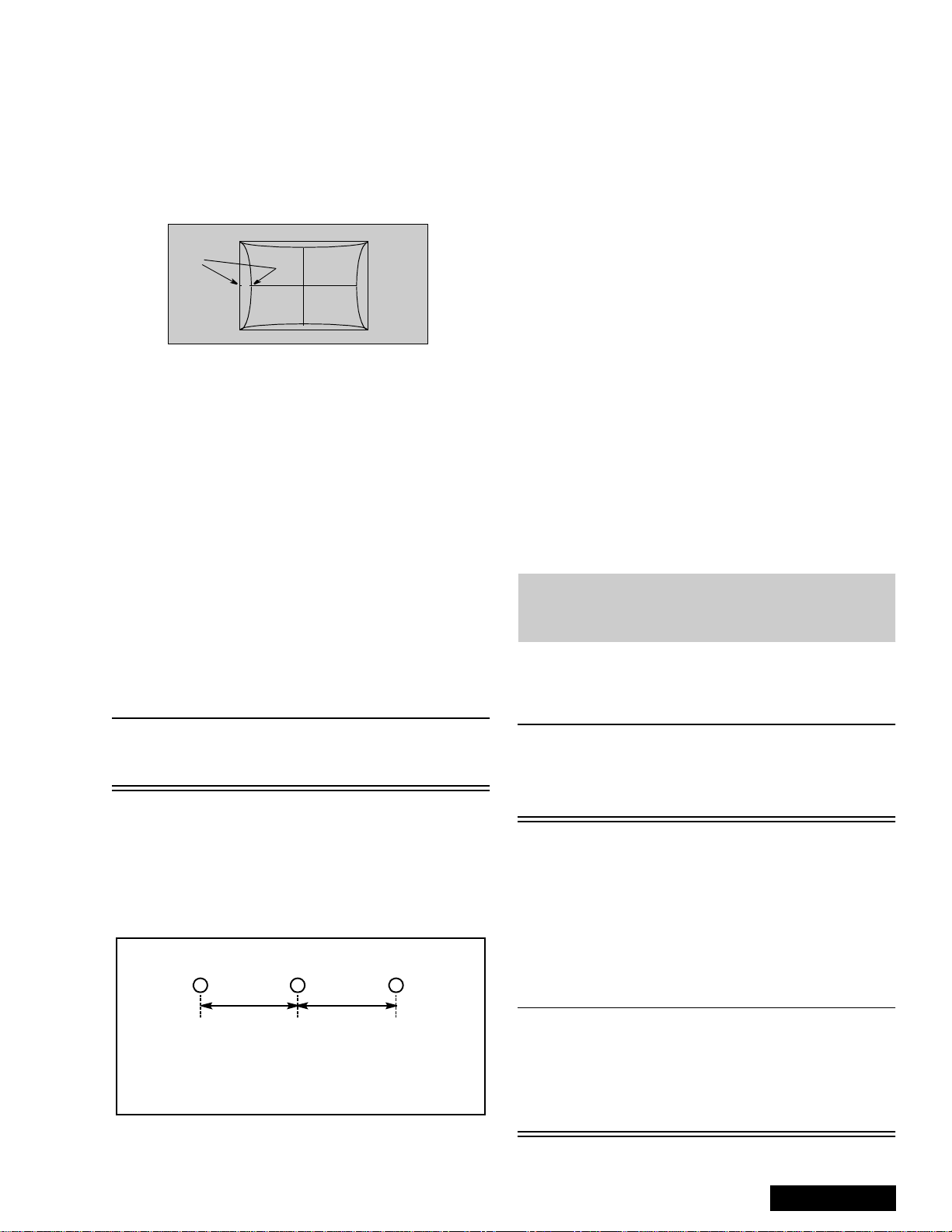
Centering Magnets Adjustment
Procedures:
1. Apply a monoscope pattern.
2. Cover the red and blue lens so only the green lens
is projecting the monoscope pattern.
3. Set DAC D0F from 0 to 1 (disabling digital
convergence).
4. Loosen the deflection coil screw on the green CRT.
5. Adjust green deflection coil until the horizontal
center line is in line with the grid and is leveled.
6. Adjust centering magn ets until the gr een pattern is
equal on left and right. Adjust also for horizontal
and vertical tilt.
9. Transfer lens cover from blue to red, so that blue is
projected.
10. Adjust blue deflection coil until the horizontal
center line match es the pattern of the grid and is
leveled.
1 1. Adjust blue centering magnets until the monoscope
pattern center is at the appropriate distance as
indicated on Figure 34.
12. Enable digital co nvergence by changing DAC D0F
from 1 to 0.
13. Following the adjustment, make sure that all
deflection coils are pus hed completely toward the
CRT cones and that all screws are tightened.
Horizontal Size Adjustment (D03)
This is the manual adjust ment of hori zontal siz e that is
included in the automatic convergence adjustment.
1. Apply a monoscope pattern.
2. Set DAC D0F from 0 to 1 (disabling digital
convergence).
3. Cover both red and blue lens.
4. In service mode, adjust H-Size DAC (D03) until the
picture horizontal s ize is 5.0
of screen.
5. Enable digital co nvergence by changing DAC D0F
from 1 to 0.
6. Remove lens covers.
0.2 lines at left side
±
Convergence Adjustment
Note: It is strongly recomm ended to first read and
understand the following section prior to
make any adjustment.
T ur n PTV on and allow it to warm up for 30
minutes prior to making adjustments
(WHITE PATTERN).
Note: Push deflection coil to top of CRT neck,
then tighten deflection screw after adjusting
each CRT centering and Tilt.
7. Transfer lens cover from r ed to green and proj ect
red only. Adjust deflection coil un til the horizontal
center line matches the pattern of the grid and is
leveled.
8. Adjust red centeri ng magnets unt il the mono scope
pattern center is at the appropriate distance as
indicated on Figure 34.
RG
dd
d measured in mm
PT-51” 28 mm
PT-61” 17 mm
Figure 34. Centering Magnets Adjustment.
B
Note: This PTV uses the scheme described
below to correct for misconvergence of the
three CRT projection tubes. There are
various modes to this operation.
Preparation:
Place the Convergence Alignment Template (see
“Convergence Alignment Template” on page 24) over
the PTV screen. Align the ce nter lines of the template
with the mechanical center markers on the PTV screen
frame. If the template is not available, create one using
the dimensions provided in “Convergence Alignment
Template” on page 24.
Remote control must be used during the procedure.
Note: Apply the Converge nce A lignment Template to
the PTV screen frame to co nverge the Green
Raster only. Remove the Convergence
Alignment Template following this alignment.
The red and blue r asters can then be a ligned
to the green raster.
- 19 -
Service Manual

Raster Setup:
1. Cover Red & Blue lens with caps.
2. Apply an NTSC monoscope pattern.
3. Select DAC V00, then press VOL right or left to
enter to “CONVERGENCE ADJ” mode.
4. Press “0” key on remote.
5. Press ACTION key on remote to enter to
“TEST_POS” mode.
6. Move pattern by pressing VOL right - le ft and CH
up - down so that the cursor center overlap
monoscope pattern center.
30
Figure 35. Aligning cross-hair
cursor with monoscope pattern
7. Press “5” key on r emote to exit superim pos e mode
(monoscope pattern disappear).
8. Press “TV/VIDEO” key to enter “DA TA_POS” mode
9. Adjust by press ing VOL right - left so that peak of
curve is the same position as center of cursor.
16. In “FINE ADJUSTMENT MODE” options, press
“MUTE” key on remote to switc h between “cursor”
mode and “data” mode.
• Cursor mode: Allows cursor movement by
pressing VOL right - left and CH up - down.
• Data mode: Allows making adjustment by
pressing VOL right - left and CH up - down.
17. Either “COARSE ADJUSTMENT MODE” options
or “FINE ADJUSTMENT MODE” options, press “RTUNE” repeatedly key on re mote to cycle through
different color adjustments (R,G,B,White)
18. To store adjustments press “7”, then “ACTION” key
on remote, otherwise press “POWER” then
“ACTION” to exit adjustments without sa ving.
19. Remote Functions:
• 1, 3. . . . . . . . . . .change color view adj
• 2. . . . . . . . . . . . . . . . . . change pattern
• 7. . . . . . . . . . . . . . . . . . . . . . . save data
• 5. . . . . . . . . . . . . . . . . . . . . . . . . overlap
• POWER. . . . . . . . . . . . . . . . . . . . to exit
• RECALL . . . . . . . . . . . . display values
• R-TUNE. . . . . . . . . . . . . . . cycle colors
• TV/VIDEO . . . . . . . . . . . .change mode
3 secs. . . . . . . change options
Coarse Adjustment Mode
Note: It is strongly recomm ended to first read and
understand the following section prior to
make any adjustment.
Figure 36. Symmetrical shape
10. Press “TV/VIDEO” key on remote to enter
“OSD_POS” mode.
11. Press “5” key on remote so that monoscope
pattern appears (superimpose mode)
12. Move cursor by pressing VOL right - left and CH
up - down so that cursor center overlap
monoscope pattern center
13. Press “0” key to go back to “CONVERGENCE
ADJ” mode.
14. Press “TV/VIDEO” key to cycle thro ugh “COARSE
ADJ. MODE” options.
Static Size Skew Linear
KeyPinCorner
Figure 37. Coarse modes cycle
15. To change to “FINE ADJUSTMENT MODE”
options (DAC V01), press “TV/VIDEO” key on
remote for at least 3 seconds, to go back to
“COARSE ADJ MOD E” options press “TV/ VIDEO”
on remote again for 3 seco nds .
Procedure:
1. Enter to “G-Size” mode:
• DAC V00
• VOL right or left
• TV/VIDEO (repeatedly)
• R-TUNE (repeatedly)
2. Press “2” repeatedly and apply the pattern of
border and cross.
3. Press RECALL to display values
4. Adjust size so that the line of t he border closes t o
the screen frame at top, bottom, left and right by
pressing CH up-down and VOL righ t-left .
Figure 38. H & V Size Adjustment
5. Press “7” then “ACTION” key on remote to save
changes.
Service Manual
- 20 -

6. Enter to linearity “G-LINEAR” mode by pressing
“TV/VIDEO”.
7. Adjust linearity by pressi ng VO L right- left unti l A=B
(See Figure 39)
AB
AB
Figure 39. Linear Mode Adjustment
8. Press “7” then “ACTION” key on remote to save
changes.
9. Enter to PIN “G-PIN” mode by pressing “TV/
VIDEO”.
10. Adjust V_PIN by pressing CH up-down (See
Figure 40).
11. Adjust H_PIN by pressing VOL right-left.
12. Press “7” then “ACTION” key on remote to save
changes.
18. Press “7” then “ACTION” key on remote to save
changes
Figure 42. KEY mode adjustment
Note: Confirm that pattern looks like a square and
almost overlaps the screen frame, check that
vertical and horizontal line center match with
the marks on screen frame, if linearity is not
good enough, repeat adjustments.
19. Enter to “STATIC” mode by pressing TV/VIDEO.
20. Press “1” or “3” repeatedly until green and red only
are shown.
21. Adjust “R-STATIC” so that the center of red
overlaps with the center of green.
Figure 40. H & V PIN Adjustment
13. Enter to CORNER “G-CORNER” mode by pressing
TV/VIDEO.
14. Adjust by pressing VOL right-left (See Figure 41).
15. Press “7” then “ACTION” key on remote to save
changes.
Figure 41. Corner Adjustment
16. Enter to KEY “G-KEY” mode by pressing TV/
VIDEO.
17. Adjust by pressing CH up-down (See Figure 42)
Red
Green
Figure 43. STATIC mode adjustment
22. Enter to SKEW “R-SK EW” mode by pressing TV/
VIDEO
23. Adjust “R-SKEW” so that the vertical and horizontal
line of center overlaps with green (See Figur e44)
24. Press “7” then “ACTION” key on remote to save
changes.
Figure 44. SKEW adjustmen t
Note: Remember always save data following each
adjustment by pressing “7” key on remote, then
ACTION.
- 21 -
Service Manual

25. Enter to LINEARITY “R-LINEAR” mode by
pressing TV/VIDEO.
26. Adjust Horizontal linearity (See Figure 39)
27. Enter to SIZE “R-SIZE” mode by pressing TV/
VIDEO
28. Adjust so that the lin e on the border closes to th e
screen frame at top, bottom, left and right (See
Figure 38)
29. Enter to PIN “R-PIN” mode by pressing TV/VIDEO
30. Adjust horizontall y and vertically (See Figure 40)
31. Enter to CORNER “R-CORNER” mode by pressing
TV/VIDEO.
32. Adjust corners (See Figure 41)
33. Enter to KEY “R-KEY” mode by pressing TV/
VIDEO
34. Adjust KEY (See Figure 42)
35. Display pattern of border and cross, then check
that red overlaps green pattern, if it is not
satisfactory, repeat from step 19.
36. Enter to STATIC “B-STATIC” mode.
37. Press “1 or 3” k ey repeatedly on remote until on ly
green and blue pattern are displayed
38. Adjust B-STATIC so that the center of blue
overlaps with the center of green (See Figure 45).
Blue
Figure 45. B-STATIC adjustment
39. Perform all adjustments for Blue (B-SKEW, BLINEAR, B-SIZE, B-PIN, B-CORNER, B-KEY)
40. Display Border and c ross pattern and confi rm that
blue overlaps with green pattern, if it is not
satisfactory, repeat for blue.
41. Press “1 or 3” key repeatedly on remote until
Green, Red and Blue (Whi te), co nfirm tha t red an d
blue overlaps with green pattern.
42. Press “7” key on remote, then ACTION to save
changes.
43. Press POWER then ACTION to exit adjustments or
press TV/VIDEO for at least 3 seconds to change
to Fine Adjustment Mode.
Green
Fine Adjustment Mode (V01)
(Convergence)
Note: It is strongly recommen ded to first read and
understand the following section prior to
make any adjustment.
Helpful Hint:
The easiest way to adjust convergence is to begin
from the center of the scree n, to the border in all the
convergence adjustments.
Remote Functions:
• 1, 3. . . . . . . . . . .change color view adj
• 2. . . . . . . . . . . . . . . . . . change pattern
• 7. . . . . . . . . . . . . . . . . . . . . . . save data
• 5. . . . . . . . . . . . . . . . . . . . . . . . . overlap
• POWER. . . . . . . . . . . . . . . . . . . . to exit
• RECALL . . . . . . . . . . . . display values
• R-TUNE. . . . . . . . . . . . . . . cycle colors
• TV/VIDEO . . . . . . . . . . . .change mode
3 secs. . . . . . . change options
• MUTE (“fine”). . . cursor & data mode
In “FINE ADJUSTMENT MODE” options, press
“MUTE” key on remote to switch between “cursor”
mode and “data” mode.
• Cursor mode (cursor flashing): Allows
cursor movement by pressing VOL right - left
and CH up - down.
• Data mode (cursor fixed): Allows making
adjustment by pressing VOL right - left and
CH up - down.
Procedure:
1. Enter to “G-EASY” mode (for green):
• DAC V01
• VOL right or left
• TV/VIDEO (repeatedly)
• R-TUNE (repeatedly)
2. Press “2” repeatedly and apply the pattern of
crosshatch.
3. Press “1 or 3” repeatedly until the pattern becomes
green.
4. Press RECALL to display values.
5. In “EASY” mode, the adjustment value changes by
4 steps
6. EASY mode allows to move lines horizontall y and
vertically from the center of cursor.
Service Manual
Cursor
Figure 46. EASY adjustment cursor Positions
- 22 -

7. This mode afects a wide area around the cursor
than other adjustment modes, See values on
screen by pressing RECALL on remote
(seeFigure 47)
8. Begin adjustment from the center to the edge of
the screen.
9. Adjust by pressin g CH up/down and VOL right/le f
on the remote control when the cursor is not
blinking, if the cursor is blinking press MUTE on the
remote.
left/right
17. Begin adjustment from the center to the edge of
the screen.
left/right
up/down
Figure 49. POINT & ORIG. POINT adjustment
up/down
Figure 47. EASY adjustment
10. To move the cursor press MUTE on the remote
(cursor blinks), then mov e the cursor to any of the
9 positions for “EASY” mode(see Figure 46)
11. This adjustment may help to make rounded lines
become straight lines
12. Adjust to make lines as straight as possible
13. Enter to POINT “G-POINT” (for green) mode by
pressing TV/VIDEO.
14. “POINT” mode allows to move line horizontally and
vertically from the perimeter of cursor making
rounded lines become strai ght (See Figure 48)
15. In “POINT” mode, the ad justm ent data c hanges by
2 steps, See values on screen by pressing
RECALL on remote.
Screen
Frame
18. Adjust to make lines as much straight as possible
19. When slightly adjustment is needed, use “ORIG.
POINT” mode.
20. To enter to “G-ORIG. POINT” (for green) mode
press TV/VIDEO.
21. With “ORIG. POINT”, the adjustment data changes
by 1 step, this allows more detail in the adjustment.
See values on screen by pressing RECALL on
remote
22. Confirm that green adjustmen t is good enough, if
adjustment is not satisfactory, repeat adjustments.
23. Enter to LINE “G-LINE” mode by pressing TV/
VIDEO.
24. LINE mode allows to move each single line
horizontally and vertically (See Figure 51).
25. Begin adjustment from the center to the edge of
the screen (see Figure 50)
26. Adjust to make distribute lines
Screen
Frame
Cursor
Blinks
Figure 48. POINT & ORIG. POINT cursor positions
16. When the cursor is locate d in the outer area of the
border the cursor starts to blink from one side to
other and the adjustment is for the non-visible area
(inside the ovals area, see Fig ure 48); This applies
to “POINT” & “ORIGIN. POINT” modes.
Figure 50. LINE adjustment cursor Positions
27. Then press “1 or 3” on the remote until red and
green appears.
Note: Since convergence adjustment will not
allows to adjust every single cross section
of the grid, it is very important to adj ust, so
that overall looks best.
- 23 -
Service Manual
 Loading...