

Pioneer PRVLX-10 Service manual
PIONEER CORPORATION 4-1, Meguro 1-chome, Meguro-ku, Tokyo 153-8654, Japan
PIONEER ELECTRONICS (USA) INC. P.O. Box 1760, Long Beach, CA 90801-1760, U.S.A.
PIONEER EUROPE NV Haven 1087, Keetberglaan 1, 9120 Melsele, Belgium
PIONEER ELECTRONICS ASIACENTRE PTE. LTD. 253 Alexandra Road, #04-01, Singapore 159936
PIONEER CORPORATION 2005
ORDER NO.
RRV3069
PRV-LX10
DVD RECORDER
PRV-LX10
THIS MANUAL IS APPLICABLE TO THE FOLLOWING MODEL(S) AND TYPE(S).
Model Type Power Requirement Remarks
PRV-LX10 WYV/RB AC220- 240V
• Before returning the repaired product to the user, be sure to upgrade the firmware to its
latest version.
For details, refer to "Important Check Points for good Servicing".
T-ZZY JAN. 2005 printed in Japan
1234
SAFETY INFORMATION
A
This service manual is intended for qualified service technicians ; it is not meant for the casual do-ityourselfer. Qualified technicians have the necessary test equipment and tools, and have been trained
to properly and safely repair complex products such as those covered by this manual.
Improperly performed repairs can adversely affect the safety and reliability of the product and may
void the warranty. If you are not qualified to perform the repair of this product properly and safely, you
should not risk trying to do so and refer the repair to a qualified service technician.
WARNING
This product contains lead in solder and certain electrical parts contain chemicals which are known to the state of California to cause
cancer, birth defects or other reproductive harm.
B
NOTICE
(FOR CANADIAN MODEL ONLY)
Fuse symbols (fast operating fuse) and/or (slow operating fuse) on PCB indicate that replacement parts must
be of identical designation.
REMARQUE
(POUR MODÈLE CANADIEN SEULEMENT)
Les symboles de fusible (fusible de type rapide) et/ou (fusible de type lent) sur CCI indiquent que les pièces
de remplacement doivent avoir la même désignation.
C
(FOR USA MODEL ONLY)
Health & Safety Code Section 25249.6 – Proposition 65
1. SAFETY PRECAUTIONS
The following check should be performed for the
continued protection of the customer and service
technician.
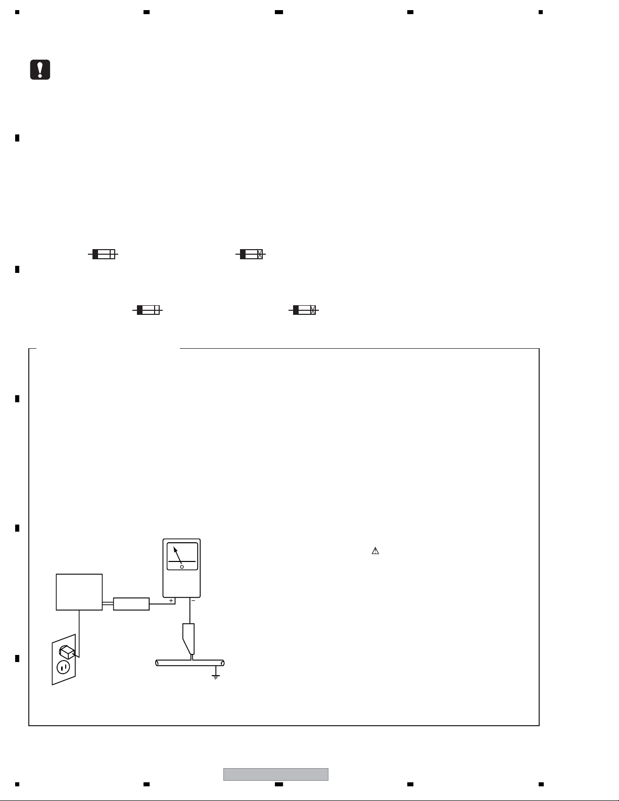
LEAKAGE CURRENT CHECK
Measure leakage current to a known earth ground (water
pipe, conduit, etc.) by connecting a leakage current tester
such as Simpson Model 229-2 or equivalent between the
D
earth ground and all exposed metal parts of the appliance
(input/output terminals, screwheads, metal overlays, control
shaft, etc.). Plug the AC line cord of the appliance directly
into a 120V AC 60Hz outlet and turn the AC power switch
on. Any current measured must not exceed 0.5mA.
Reading should
Leakage
Device
E
under
test
Also test with
plug reversed
(Using AC adapter
plug as required)
Test all
exposed metal
surfaces
current
tester
not be above
0.5mA
Earth
ground
ANY MEASUREMENTS NOT WITHIN THE LIMITS
OUTLINED ABOVE ARE INDICATIVE OF A POTENTIAL
SHOCK HAZARD AND MUST BE CORRECTED BEFORE
RETURNING THE APPLIANCE TO THE CUSTOMER.
2. PRODUCT SAFETY NOTICE
Many electrical and mechanical parts in the appliance
have special safety related characteristics. These are
often not evident from visual inspection nor the protection
afforded by them necessarily can be obtained by using
replacement components rated for voltage, wattage, etc.
Replacement parts which have these special safety
characteristics are identified in this Service Manual.
Electrical components having such features are identified
by marking with a
in this Service Manual.
The use of a substitute replacement component which does
not have the same safety characteristics as the PIONEER
recommended replacement one, shown in the parts list in
this Service Manual, may create shock, fire, or other hazards.
Product Safety is continuously under review and new
instructions are issued from time to time. For the latest
information, always consult the current PIONEER Service
Manual. A subscription to, or additional copies of, PIONEER
Service Manual may be obtained at a nominal charge from
PIONEER.
on the schematics and on the parts list
AC Leakage Test
F
2
1234
PRV-LX10
5678
THIS PIONEER APPARATUS CONTAINS
IMPORTANT
INVISIBLE LASER OF CLASS 3b and VISIBLE
LASER OF CLASS 2.
SERVICING OPERATION OF THE APPARATUS
SHOULD BE DONE BY A SPECIALLY
INSTRUCTED PERSON.
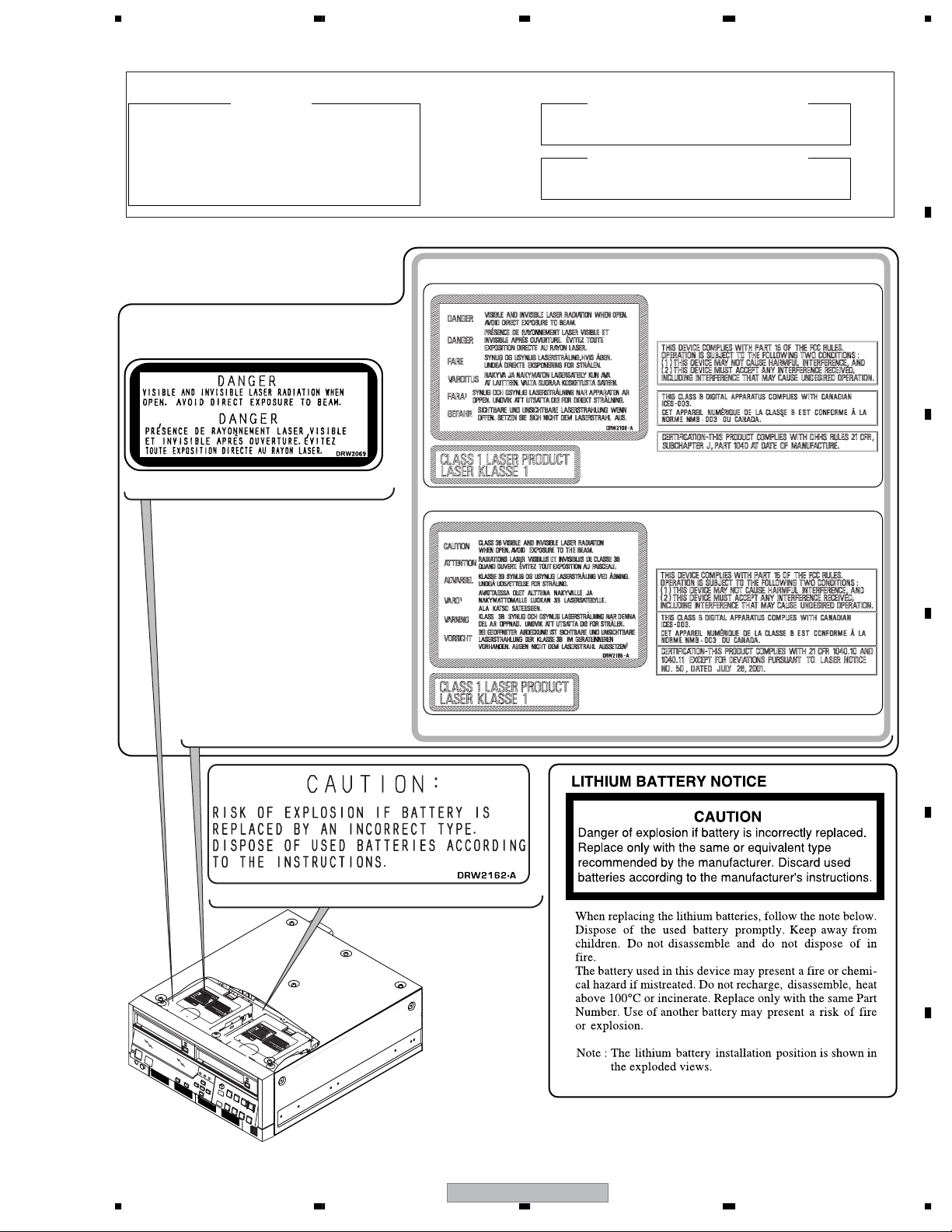
LABEL CHECK
Note: You will see one of the following two labels attached.
DRIVE Assy LX1
(DRW2069)
LASER DIODE CHARACTERISTICS
MAXIMUM OUTPUT POWER: 25 mW
WAVELENGTH: 654 - 662 nm
LASER DIODE CHARACTERISTICS
MAXIMUM OUTPUT POWER: 36 mW
WAVELENGTH: 780 - 787 nm
A
B
(DRW2109)
C
(DRW2162)
(DRW2185)
D
E
F
56
PRV-LX10
3
7
8
1234
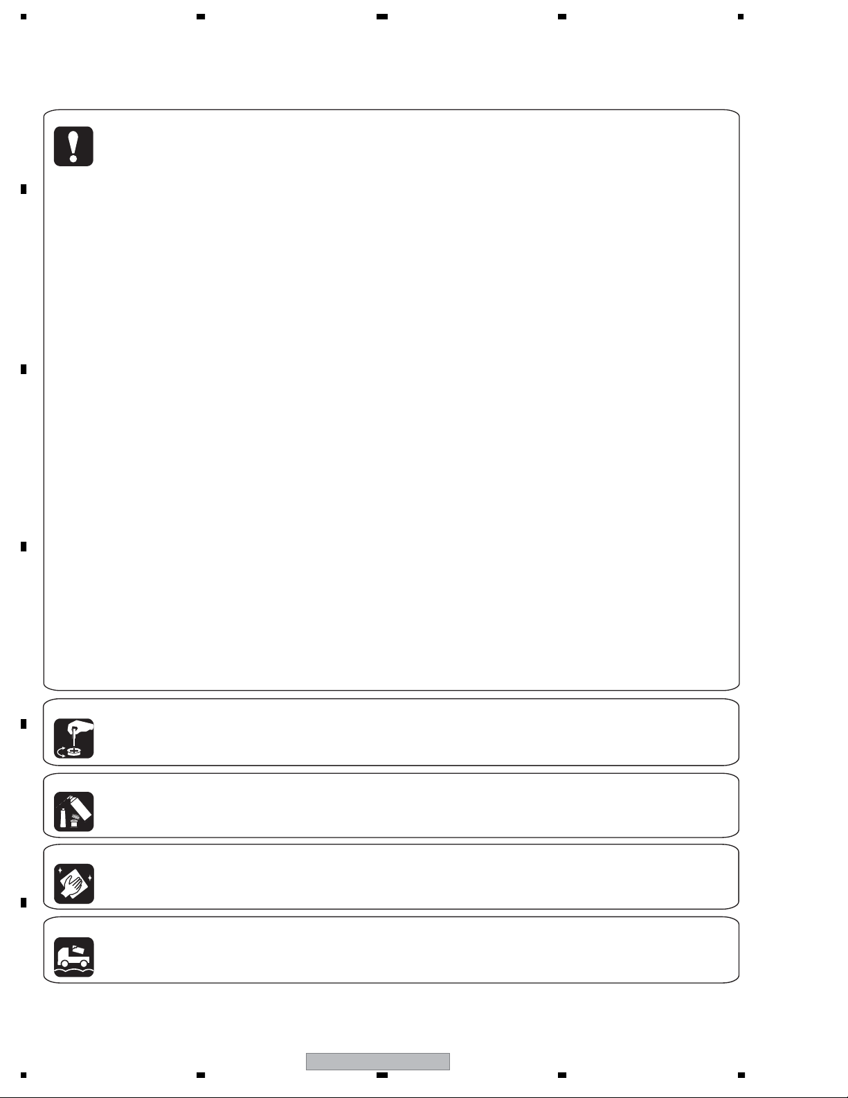
[Important Check Points for Good Servicing]
In this manual, procedures that must be performed during repairs are marked with the below symbol.
Please be sure to confirm and follow these procedures.
A
1. Product safety
Please conform to product regulations (such as safety and radiation regulations), and maintain a safe servicing environment by
following the safety instructions described in this manual.
1 Use specified parts for repair.
Use genuine parts. Be sure to use important parts for safety.
2 Do not perform modifications without proper instructions.
Please follow the specified safety methods when modification(addition/change of parts) is required due to interferences such as
radio/TV interference and foreign noise.
B
C
D
3 Make sure the soldering of repaired locations is properly performed.
When you solder while repairing, please be sure that there are no cold solder and other debris.
Soldering should be finished with the proper quantity. (Refer to the example)
4 Make sure the screws are tightly fastened.
Please be sure that all screws are fastened, and that there are no loose screws.
5 Make sure each connectors are correctly inserted.
Please be sure that all connectors are inserted, and that there are no imperfect insertion.
6 Make sure the wiring cables are set to their original state.
Please replace the wiring and cables to the original state after repairs.
In addition, be sure that there are no pinched wires, etc.
7 Make sure screws and soldering scraps do not remain inside the product.
Please check that neither solder debris nor screws remain inside the product.
8 There should be no semi-broken wires, scratches, melting, etc. on the coating of the power cord.
Damaged power cords may lead to fire accidents, so please be sure that there are no damages.
If you find a damaged power cord, please exchange it with a suitable one.
9 There should be no spark traces or similar marks on the power plug.
When spark traces or similar marks are found on the power supply plug, please check the connection and advise on secure
connections and suitable usage. Please exchange the power cord if necessary.
0 Safe environment should be secured during servicing.
When you perform repairs, please pay attention to static electricity, furniture, household articles, etc. in order to prevent injuries.
Please pay attention to your surroundings and repair safely.
2. Adjustments
To keep the original performance of the products, optimum adjustments and confirmation of characteristics within specification.
Adjustments should be performed in accordance with the procedures/instructions described in this manual.
3. Lubricants, Glues, and Replacement parts
E
Use grease and adhesives that are equal to the specified substance.
Make sure the proper amount is applied.
4. Cleaning
For parts that require cleaning, such as optical pickups, tape deck heads, lenses and mirrors used in projection monitors, proper
cleaning should be performed to restore their performances.
5. Shipping mode and Shipping screws
To protect products from damages or failures during transit, the shipping mode should be set or the shipping screws should be
installed before shipment. Please be sure to follow this method especially if it is specified in this manual.
F
4
1234
PRV-LX10
5678
• Recordable discs • Playback only discs
LogoLogo Attributes
12cm, single-sided, single layer disc
Approx. max. recording time: 360
DVD-RW
minutes (4.7GB)
DVD video
12cm, double-sided, single layer disc
Approx. max. recording time: 720
minutes (9.4GB)
DVD-R
∗ This unit does not support use of 8 cm DVD-R discs.
• CD-R/CD-RW discs cannot be recorded on this unit.
CONTENTS
1. SPECIFICATIONS
1.1 SPECIFICATIONS CHECKS ......................................................................................................................7
1.2 FUNCTION MENU......................................................................................................................................9
1.3 SPECIFICATIONS ....................................................................................................................................12
2. EXPLODED VIEWS AND PARTS LIST
2.1 PACKING..................................................................................................................................................14
2.2 EXTERIOR SECTION (1/3)......................................................................................................................16
2.3 EXTERIOR SECTION (2/3)......................................................................................................................18
2.4 EXTERIOR SECTION (3/3)......................................................................................................................20
2.5 REAR PANEL SECTION ..........................................................................................................................22
2.6 FRONT PANEL SECTION ........................................................................................................................24
3. BLOCK DIAGRAM AND SCHEMATIC DIAGRAM
3.1 BLOCK DIAGRAM
3.1.1 OVERALL BLOCK DIAGRAM
3.1.2 I/O BLOCK
3.1.3 DECB ASSY
3.1.4 PCIB ASSY
3.1.5 AVIB ASSY
3.1.6 PWRB, FLKB, KEYB, DRV1B, DRV2B and USBB ASSYS
3.1.7 PWRB ASSY
3.1.8 WAVEFORMS
3.2 OVERALL WIRING DIAGRAM
3.3 JKIB ASSY (1/3)
3.4 JKIB ASSY (2/3)
3.5 JKIB ASSY (3/3)
3.6 JKDB and 422IB ASSYS
3.7 HPVB and JKOB ASSYS
3.8 DECB ASSY (1/2)
3.9 DECB ASSY (2/2)
3.10 PCIB ASSY (1/4)
3.11 PCIB ASSY (2/4)
3.12 PCIB ASSY (3/4)
3.13 PCIB ASSY (4/4)
3.14 AVIB ASSY (1/6)
3.15 AVIB ASSY (2/6)
3.16 AVIB ASSY (3/6)
3.17 AVIB ASSY (4/6)
3.18 AVIB ASSY (5/6)
3.19 AVIB ASSY (6/6)
3.20 PWRB(POLY) ASSY
3.21 FLKB(WYV/RB) ASSY
3.22 KEYB(WYV/RB) ASSY
.............................................................................................................................................................
.......................................................................................................................
.....................................................................................................
....................................................................................................................................................
.........................................................................................................................
..........................................................................................................................................................
.......................................................................................................................................................
.........................................................................................................................................................
.........................................................................................................................................................
.......................................................................
......................................................................................................................................................
....................................................................................................................................................
...............................................................................................................................
.......................................................................................................................................................
.......................................................................................................................................................
.......................................................................................................................................................
.........................................................................................................................................
........................................................................................................................................
.....................................................................................................................................................
.....................................................................................................................................................
....................................................................................................................................................
....................................................................................................................................................
....................................................................................................................................................
....................................................................................................................................................
.....................................................................................................................................................
.....................................................................................................................................................
.....................................................................................................................................................
.....................................................................................................................................................
.....................................................................................................................................................
.....................................................................................................................................................
..............................................................................................................................................
..........................................................................................................................................
..........................................................................................................................................
14
26
26
26
28
29
30
31
33
34
35
40
42
44
46
48
50
52
54
56
58
60
62
64
66
68
70
72
74
76
78
80
A
B
7
C
D
E
F
56
PRV-LX10
5
7
8

1234
3.23 DRV1B and DRV2B ASSYS
3.24 USBB ASSY
4. PCB CONNECTION DIAGRAM
4.1 JKIB, JKDB, 422IB and HPVB ASSYS
A
4.2 DECB ASSY
4.3 PCIB ASSY
4.4 AVIB ASSY
................................................................................................................................................................
................................................................................................................................................................
4.5 PWRB ASSY
4.6 FLKB, KEYB, DRV1B, DRV2B and USBB ASSYS
4.7 JKOB ASSY
4.8 MOTHER BOARD ASSY
5. PCB PARTS LIST
6. ADJUSTMENT
...............................................................................................................................................................
6.1 27MHz CLOCK ADJUSTMENT
7. GENERAL INFORMATION
7.1 DIAGNOSIS
B
7.1.1 TESTMODE
7.1.2 TEST MODE CODE
7.1.3 LED SPECIFICATIONS
7.1.4 POWER-ON SEQUENCE
7.1.5 HOW TO CHECK THE ERROR LOG
7.1.6 ERROR LOG DISPLAY
7.1.7 DEBUGGING DISPLAY MODE
7.1.8 LIST OF BIOS SETTING VALUE
7.1.9 REWRITING OF THE GUIDS
7.1.10 CAUTIONS ON HANDLING THE HDD
7.1.11 HDD REPLACEMENT PROCEDURES
7.1.12 HOW TO CHECK THE HDD.......................................................................................................... 149
C
7.1.13 CLEANING
7.1.14 HOW TO INSTALL THE OS OR PROGRAM
7.1.15 TROUBLE SHOOTING
7.1.16 DISASSEMBLY.............................................................................................................................. 158
7.2 IC INFORMATION
8. PANEL FACILITIES
................................................................................................................................
............................................................................................................................................................
....................................................................................................................................
.................................................................................................................
..............................................................................................................................................................
.............................................................................................................................................................
..........................................................................................
.............................................................................................................................................................
......................................................................................................................................
..........................................................................................................................................................
...........................................................................................................................
..........................................................................................................................................
.............................................................................................................................................................
.....................................................................................................................................................
.......................................................................................................................................
.................................................................................................................................
.............................................................................................................................
..........................................................................................................
..................................................................................................................................
....................................................................................................................
.................................................................................................................
.......................................................................................................................
.....................................................................................................
....................................................................................................
.....................................................................................................................................................
...........................................................................................
................................................................................................................................
..................................................................................................................................................
.......................................................................................................................................................
82
84
85
86
90
92
94
98
100
104
105
108
116
116
117
117
117
120
122
127
130
135
139
143
145
146
148
149
150
152
170
190
D
E
F
6
1234
PRV-LX10
5678
1. SPECIFICATIONS
1.1 SPECIFICATIONS CHECKS
Test Specifications
• Conditions and connections for the test
• Conditions for the test
Power voltage: PRV-LX10/WYV/RB: 220- 240V±10% AC, 50/60 Hz
Power consumption: PRV-LX10/WYV/RB: 1A max. when all optional accessories are mounted
Ambient temperature: 5-35°C, relative humidity: 85% or less
Note: Because the HDD is mounted on the unit, be sure not to impart shock or vibration to the unit while it is
operating.
• Recommended media
For the test of the unit, use the following recommended media:
DVD-R: (GGV1139)
DVD-RW: (GGV1050)
• Conditions diagram
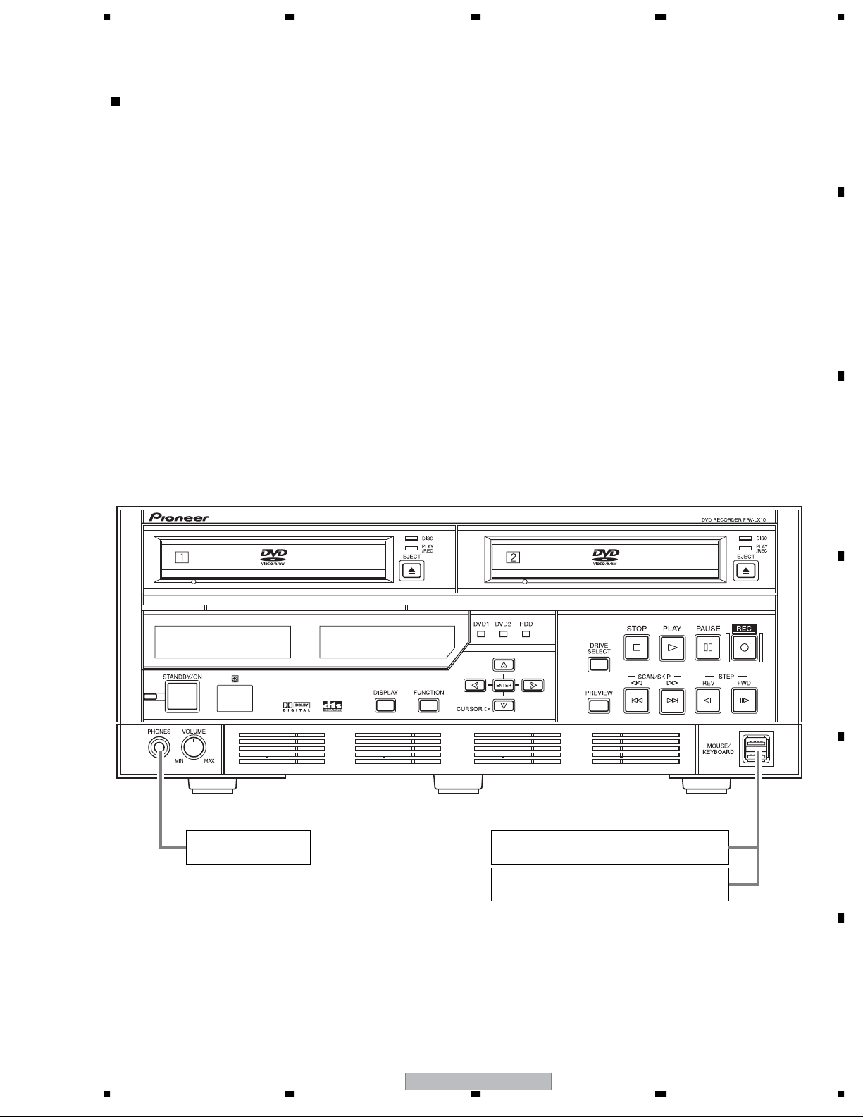
Front panel section
•
A
B
C
Standard Phones
( Impedance 32Ω)
D
E
Keyboard to be connected to the USB connector:
TK-U109JPW2 manufactured by Elecom, or equivalent
Mouse to be connected to the USB connector:
USB by Microsoft Wheel Mouse, or equivalent
F
56
PRV-LX10
7
7
8
1234
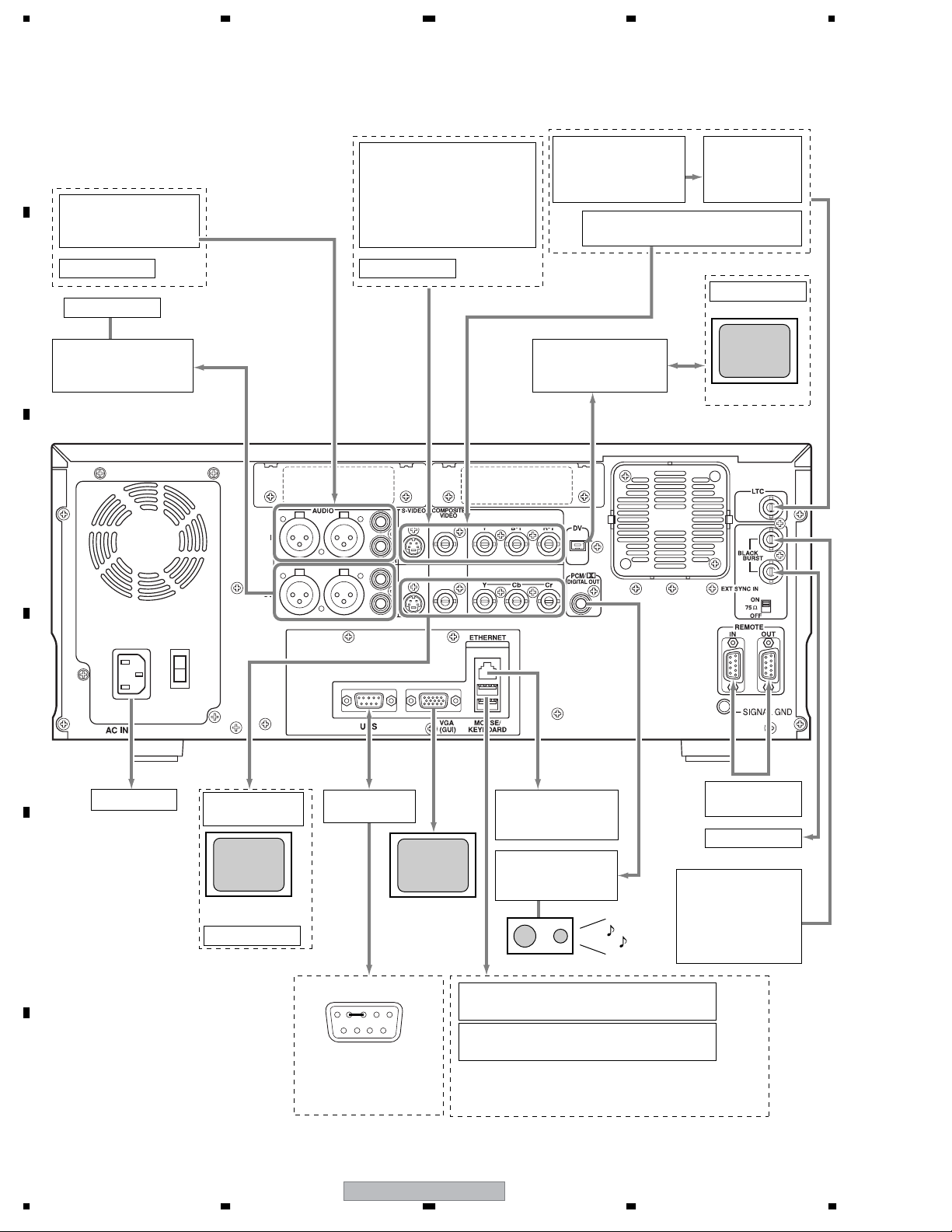
• Rear Panel section
[The connection figure of measuring instruments]
A
Audio SG
RCA : AG15B, or equivalent
XLR : AM51A, or equivalent
DVD Player
Oscilloscope
B
Audio Analyzer
RCA : AD725C, or equivalent
XLR : AM51A, or equivalent
C
Video SG ∗
[NTSC]
S/CV : MG6301A, or equivalent
Component : TSG-300, or equivalent
[PAL]
S/CV : TG19CA, or equivalent
Component : TG19CA, or equivalent
DVD Player
Media Converter
Manufactured by data video
DAC-100, or equivalent
TC Gen.
Manufactured by SONY
BVG-1600PS, or equivalent
Institutional Video recorder
Manufactured by SONY.DVCAM, or equivalent
LINE CONVERTER
Manufactured by
TASCAM
LA81, or equivalent
DVD Player
Monitor
D
AC Power supply
E
Note ∗:
According to the TV system (PAL or
NTSC) of signals to be output/input,
connect appropriate equipment to the
video input/output connectors.
F
Video Analyzer
VM700, or equivalent
Monitor
Oscilloscope
Note: 232C LoopBack Jig
For TXD-RXD loopback,
short-circuit Pin 2 and
Pin 3 of the RS232C
connector.
232C
LoopBack jig
Manufactured by iiyama
VGA Monitor
AX3819UT,
or equivalent
B.B ROUTER
Manufactured by I-O data
NP-BBRE, or equivalent
AV AMP
Manufactured by Pioneer
VSA-C100, or equivalent
Keyboard to be connected to the USB connector:
TK-U109JPW2 manufactured by Elecom, or equivalent
Mouse to be connected to the USB connector:
USB by Microsoft Wheel Mouse, or equivalent
Note: Only connect a recommended USB device to one
of the USB connectors on the rear panel. A device other
than those recommended may not be recognized on startup.
422A
Cross Cable
Oscilloscope
Video SG ∗
[NTSC]
MG6301A, or equivalent
[PAL]
TG19CA, or equivalent
(Black Burst)
8
1234
PRV-LX10
5678
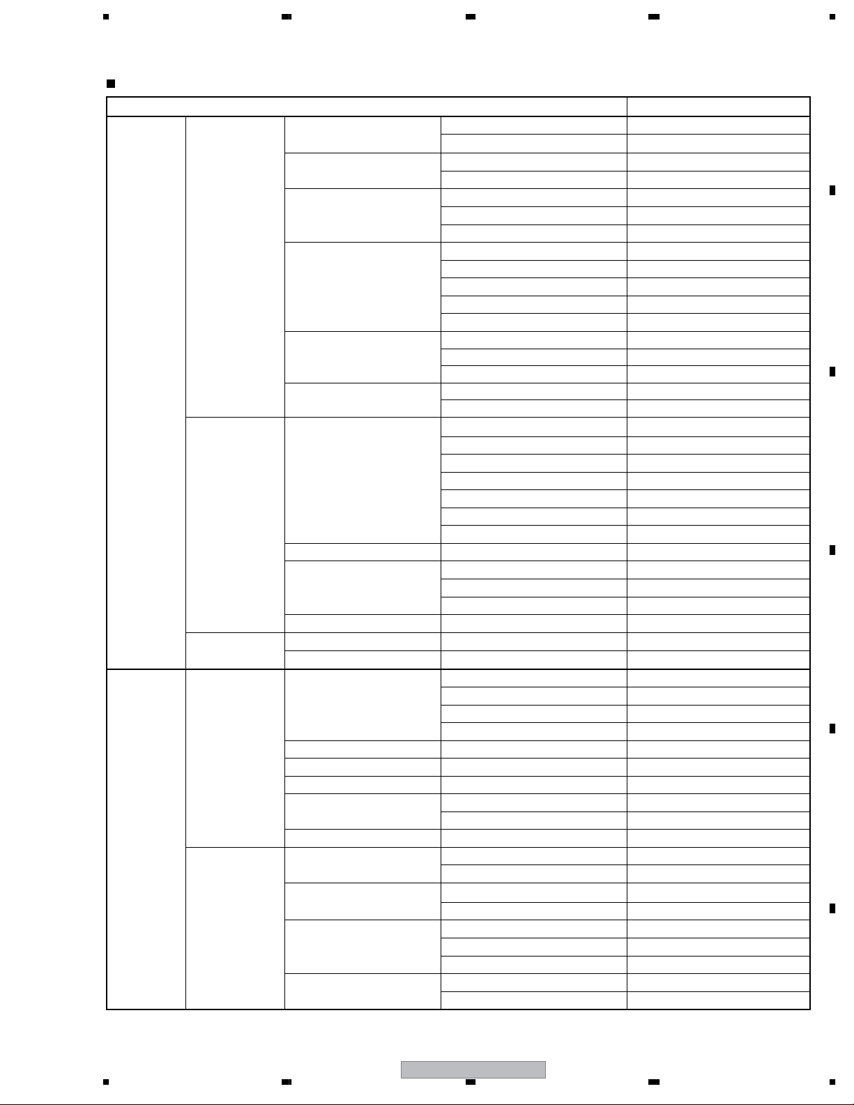
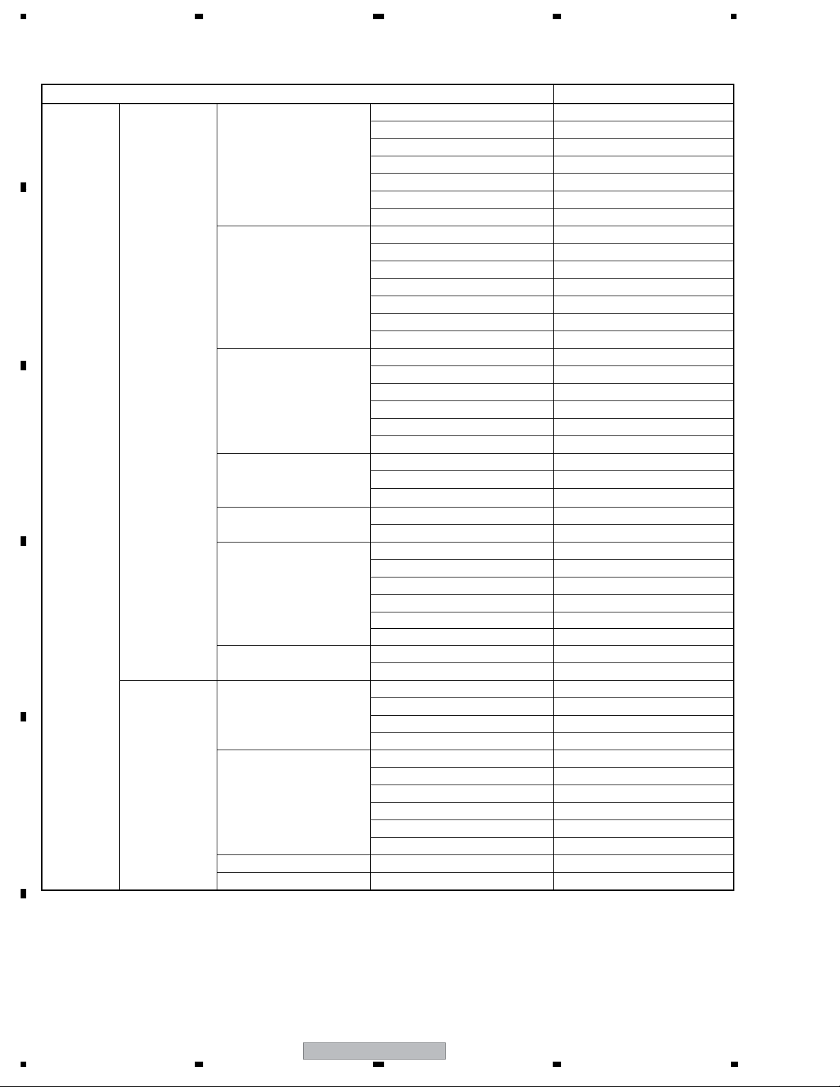
1.2 FUNCTION MENU
Function Menu Prestore (reference)
Menu Setting
Menu Type / Font
Menu Design
DVD Menu
Menu Modification
Navigation Cmd
Del/Init Library
EDIT
Record Name
Project
Copy Project Copy To
Copy Clip
Delete Delete No Item
DVD Disc
Auto Capture
APP
Copy/Impt/Bku
Make Disc
Image Target Image hyymmdd_xx.img
IN/OUT Point
Chapter Point Chapter Point 00:00:00:00
EDL Command Command Finalize
EDL
EDL Load/Delete
EDL Save
Disc Image Copy
Image Copy/Del
Menu Import
EDL Import
Menu item Setting
Menu Edit To hyymmdd_xx
Menu TV System PAL
Menu Type Title Menu
Font Helvetica
Design Select Type A
Thumbnail Go to Video
Button Text Number
Background Default
Image Default
Disc Name
Select Color Default
Active Color Default
Introduction Clip Disabled
First Play PGC Stop
Title Post Cmd Stop
Type Background
Design Select BG2.bmp
Name hyymmdd_xx
Protect Disabled
Record To HDD
Num of Clips 0
Num of Titles 0
Last Modified Date yyyy.mm.dd hh:mm:ss
Total Capacity 0 MB
Source Drive HDD
Copy From No Item
Clip No Item
Target DVD 1
Preroll Time 5 Seconds
Offsest(Frame) -17 Frames
Record As Title(Stop)
IN/OUT Point 00:00:00:00
No Item
Load No Item
Delete No Item
Save To edl000.edl
Source DVD 1
Input Image Name disc00000.img
Source Image No Item
Destination DVD 1
Type Background
Source Import Directory
Source File No Item
Source Import Directory
Source File No Item
(Blank)
cx_hyymmdd_xx
(Blank)
A
B
C
D
E
F
56
PRV-LX10
9
7
8
1234
A
B
C
D
E
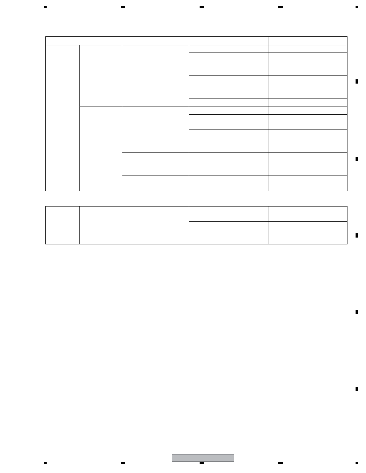
SET UP
System
Operation
Menu item Setting
Keyboard English(GB)
Key Repeat Speed Medium
Mouse Generic
System Settings
F-Key Set 1 - 6
F-Key Set 7 - 12
Network
UPS Setting
Information
HDD Tools
Control Settings
Video Settings
HDD Recording Time Shift PLAY Enabled
Info Language Language English(GB)
Mouse Speed Medium
Time Zone London
Date(mm/dd/yyyy) mm/dd/yyyy
Time(hh:mm:ss) hh:mm:ss
F-Key Enable F-Key Only
F1 Not Set
F2 Not Set
F3 Not Set
F4 Not Set
F5 Not Set
F6 Not Set
F7 Not Set
F8 Not Set
F9 Not Set
F10 Not Set
F11 Not Set
F12 Not Set
Network OFF
DHCP/Manual DHCP
MAC Address ---.---.---.--Model Disabled
Shutdown Delay 30 seconds
System Version
Power-On Time xxxx(h)
HDD Access xxxx(h)
Drive 1(R/W) xxxx(h)/xxxx(h)
Drive 2(R/W) xxxx(h)/xxxx(h)
Service Info x
Target Drive HDD
Remaining Capacity 100.87(GB)
Control Local
Port RS-422A
Time Code RS-422A
Eject Setting Eject
External Sync Disabled
OSD Enabled
Composite Out Source Monitor
Background Color Black
DV OUT Disabled
Test Signal Start
x.xx-x/x.xx
F
10
1234
PRV-LX10
5678
Recording
SETUP
Playback
TOP STATUS
Video/Audio
Others
Video
Audio
Language
Others
Menu item Setting
Video Encode Rate 9.644Mbps
Video Filter(NR) OFF
Audio Encode Dolby Digital
Audio Level L : +0 / R : +0
Aspect 4:3
Setup Level (Blank)
Auto Chapter Manual
REC Button REC Start
Aspect 4:3(LB)
Still Mode Frame
Dolby Digital OUT Dolby Digital
DTS OUT OFF
96kHz PCM OUT Convert To 48kHz
MPEG OUT MPEG
Audio English
Subtitle English
DVD Menu English
Parental Level 8
Country Code us
Drive HDD
Project [NEW]hyymmdd_xx
V Input Composite
A Input RCA
TV System PAL
A
B
C
Factory-preset values for the main unit
• Front panel
Setting of the VOLUME control: MIN
• Rear panel
Setting of the Terminate switch: ON (upper position)
D
E
F
56
PRV-LX10
11
7
8

1234
1.3 SPECIFICATIONS
• DVD RECODER [PRV-LX10]
A
General
Power rating : AC 220V- 240V, 50/60 Hz
Power consumption : Maximum 1.0 A
Power consumption during Standby : 6.5 W
Peak inrush current (Power on) : 30 A
Weight : 16.5 kg (36 lb 6 oz)
External dimensions : 427 (W) x 179.5 (H) x 539.5 (D) mm (including projecting parts)
16-13/16 (W) x 7-1/16 (H) x 21-1/4 (D) in (including projecting parts)
Ambient temperature during use : +5 °C to +35 °C (+41 °F to +95 °F)
Ambient humidity during use : 5 - 85% RH (without condensation)
Recording
B
Recording format : DVD: DVD-Video
HDD : VOB FILE
Recordable discs : DVD-R
DVD-RW
Video recording format
Sampling frequency : 13.5 MHz
Compression : MPEG
Audio recording format
Sampling frequency : 48 kHz
Compression format : Dolby Digital and Linear PCM (non-compressed)
C
Recording time
DVD-R/RW (manual rate) : About 1 - 6 hours
HDD (manual rate) : About 23 - 100 hours
Playback
Playable discs : DVD-Video, DVD-R, DVD-RW
(CD-R, CD-RW, and CD-ROM are supported for data read only)
Video input
Composite : BNC x 1, 1.0 Vp-p, 75 Ω
S-VIDEO : 4-pin mini DIN x 1
D
Y: 1.0 Vp-p, 75 Ω
C: 0.286 Vp-p (NTSC), 0.300 Vp-p (PAL), 75 Ω
Component : BNC x 3
Y: 1.0 Vp-p, 75 Ω
B-Y: 0.525/0.7 Vp-p selectable (NTSC), 0.525 Vp-p (PAL), 75 Ω (with 75% color bar)
R-Y: 0.525/0.7 Vp-p selectable (NTSC), 0.525 Vp-p (PAL), 75 Ω (with 75% color bar)
Video Output
Composite : BNC x 1, 1.0 Vp-p, 75 Ω
S-VIDEO : 4P mini DIN x 1
E
Component : BNC x 3
S/N ratio : Composite/S-VIDEO(Y)/Component(Y): More than 60 dB (playback)
Y:1.0 Vp-p, 75 Ω
C: 0.286 Vp-p (NTSC), 0.300 Vp-p (PAL), 75 Ω
Y: 1.0 Vp-p, 75 Ω
Pb: 0.7 Vp-p, 75 Ω
Pr: 0.7 Vp-p, 75 Ω
F
12
1234
PRV-LX10
5678
Audio input
L, R: unbalanced: Pin jack x 2, 2 Vrms (0 dBfs), 22 k Ω(or more)
CH1 (L), CH2 (R) : balanced: XLR (female) x 2, +4 dBu, 600Ω
Audio output
L, R: unbalanced : Pin jack x 2, 2 Vrms (0 dBfs), 1.5 k Ω(or less)
Frequency response : 4 Hz to 22 kHz (DVD fs: 48 kHz)
S/N ratio : More than 60 dB
Distortion (THD+N) : Less than 0.02 %
CH1 (L), CH2 (R): balanced : XLR (male) x 2, 0 dBu, 600 Ω load, low-impedance
Frequency response : 4 Hz to 22 kHz (DVD fs: 48 kHz)
S/N ratio : More than 60 dB
Distortion (THD+N) : Less than 0.02 %
Digital: unbalanced : Pin jack x 1, 0.5 Vp-p, 75 Ω
External Sync Input
: BNC x 2, black burst, 0.286 Vp-p (NTSC), 0.300 Vp-p (PAL), 75 Ω (ON/OFF)
Other:
DV input/output : 4 pin (i.Link/IEEE 1394 compatible) x 1
LTC input : BNC x 1, 0.5-8 Vp-p, 3 kΩ
Remote input : D-sub 9-pin (female) RS-422A compatible x 1 (Inch threads)
Remote output : D-sub 9-pin (female) RS-422A compatible x 1 (Inch threads)
UPS control : D-sub 9-pin (male) RS-232C compatible x 1 (Inch threads)
VGA output : Mini D-sub 15-pin (female) x 1 (Inch threads)
Mouse/keyboard connectors : 4P type A (USB 2.0 compatible) x 4
Ethernet : 8P type (IEEE802.3 compatible, category 5) x 1
A
B
C
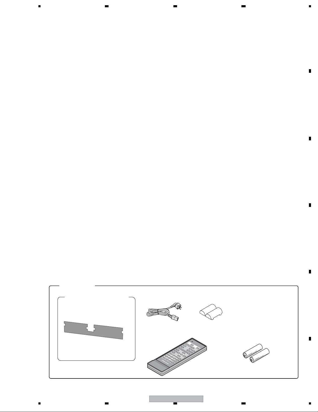
Accessories:
Remote control unit .............................................. 1
AA batteries ......................................................... 2
Air filter replacement set ...................................... 1
Power cord ........................................................... 1
Ferrite core ........................................................... 1
Operating Instructions .......................................... 1
GE Sub Manual .................................................... 1
¶ Specifications and appearance are subject to change without notice.
[ Accessories ]
Power cord: x1
Air filter replacement set:
(ADG1214)
Air filter: x4
(DEC2530)
Remote control unit : x1
(DXX2527)
Air Filter Replacement
Instructions and Precautions: x1
(DRH1078)
S
ET
U
P
12
45
7
0
8
10
>
9
C
LE
AR
SEA
R
C
H
D
X
X
2527
D
Ferrite core: x1
(DTX1007)
Operating Instructions: x1
GE Sub Manual: x1
E
AA batteries (R6P,AA): x2
R
EPEA
S
TO
T
P
RP
D
T
ISPL
A
-B
AY
AU
D
IO
PAU
PL
SE
A
N
G
LE
S
M
UB
EN
U
T
O
M
P
E
NU
EN
T
ER
3
R
ETU
6
R
N
TIT
FR
LE
M
/CH
/T
IM
P
E
F
R
M
/T
IM
E
AY
S
TEP
T
IT
L
E
SC
A
PR
N
EV
NE
XT
56
PRV-LX10
F
13
7
8
1234
2. EXPLODED VIEWS AND PARTS LIST
NOTES:
A
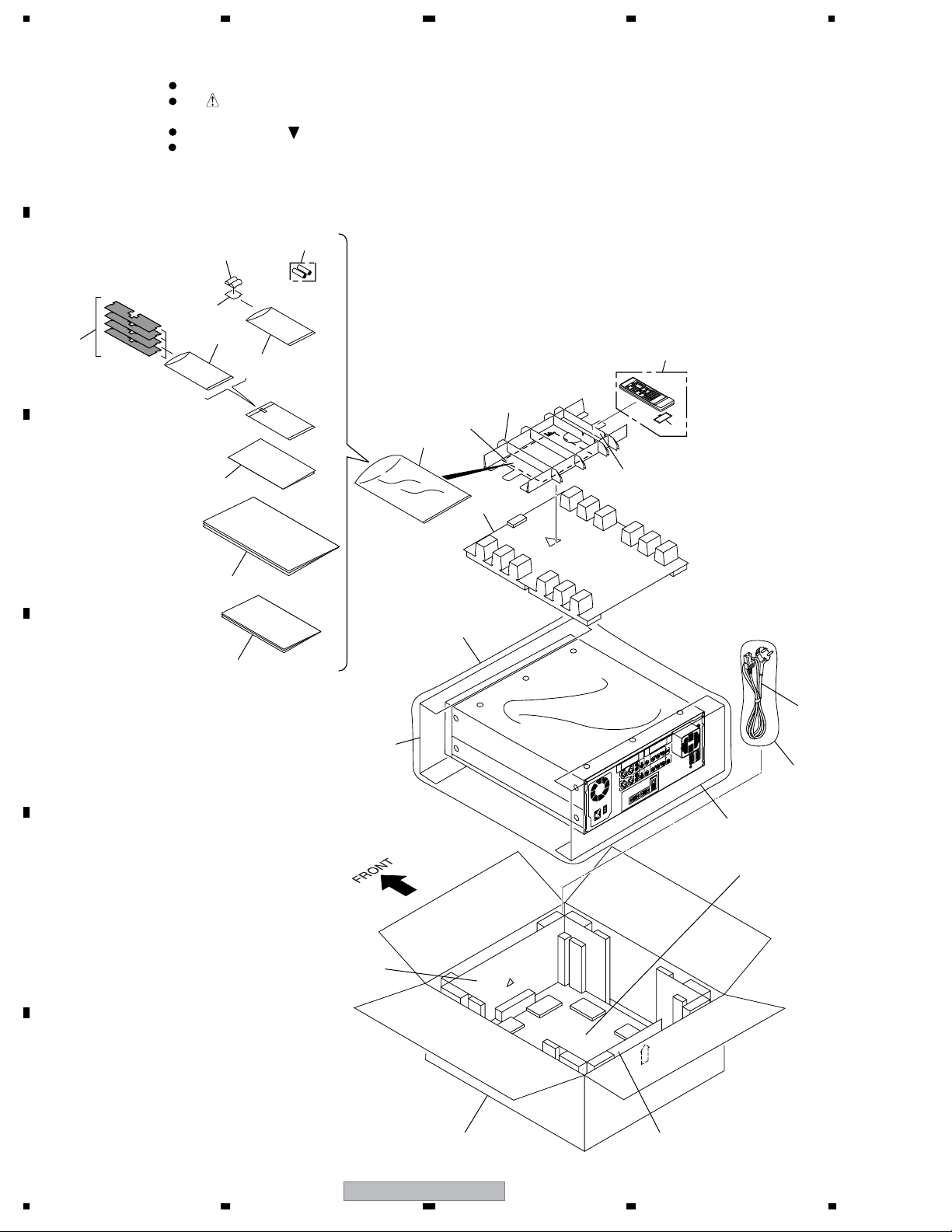
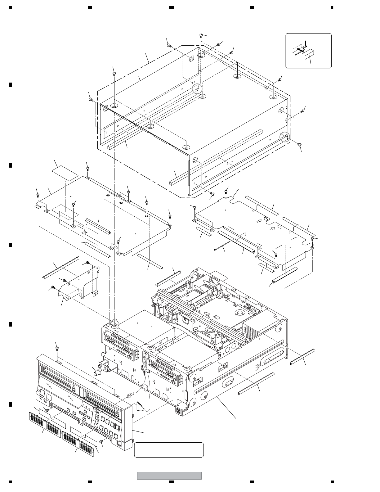
2.1 PACKING
B
×4
2
C
Parts marked by "NSP" are generally unavailable because they are not in our Master Spare Parts List.
The mark found on some component parts indicates the importance of the safety factor of the part.
Therefore, when replacing, be sure to use parts of identical designation.
Screws adjacent to mark on product are used for disassembly.
For the applying amount of lubricants or glue, follow the instructions in this manual.
(In the case of no amount instructions, apply as you think it appropriate.)
23
19
9
4
7
8
13
15
10
16
5
6
14
3
21
24
D
22
22
11
E
17
1
10
F
14
20
PRV-LX10
1234
18

5678
PACKING Parts List
No. Description Part No.
Mark
1Power Cord ADG1214
2 Air Filter DEC2530
3 Operating Instructions DRE1028
(English/French)
4 Air Filter Replacement DRH1078
Instructions and Precautions (EU)
5 Remote Control Unit DXX2527
6 Battery Cover VNK4403
NSP 7 Dry Cell Battery (R6P, AA) VEM1031
NSP 8 Polyethylene Bag Z21-004
(60 x 120 x 0.03)
NSP 9 Polyethylene Bag Z21-010
(100 x 230 x 0.018)
NSP 10 Polyethylene Bag Z21-019
(235 x 320 x 0.06)
11 Bottom Pad DHA1571
12 • • • • •
13 Accessory Plate DHA1651
14 Accessory Plate 2 DHA1652
15 Accessory Base DHA1653
16 Top Pad 2 DHA1655
17 F Pad 2 DHA1656
18 R Pad 2 DHA1657
19 FE Sheet 2 DHA1675
20 Packing Case EU DHG2456
21 Mirror Mat Bag DHL1124
22 Packing Sheet RHC1052
23 Ferrite Core DTX1007
NSP 24 GE Sub Manual DRH1084
>
A
B
C
D
56
PRV-LX10
E
F
15
7
8
1234
2.2 EXTERIOR SECTION (1/3)
18
A
1
18
2
18
B
∗2
18
18
18
Note ∗2: Gasket locations
Bonnet
Gasket B
18
18
∗2
3
7
8
17
C
17
17
10
17
17
17
3
17
9
17
18
11
∗3
17
10
12
∗3
19
D
19
19
10
14
∗3
13
16
12
∗3
13
14
17
∗3
18
11
17
15
17
∗3
E
6
17
4
To MOTHER
(COM2)
To PWRB
(CN3)
∗3
12
14
∗1
Refer to
Refer to
5
F
5
∗1
17
6
16
1234
"2.6 FRONT PANEL SECTION".
Note ∗1:
When removing the front panel section,
be sure to remove this screw.
PRV-LX10
"2.3 EXTERIOR SECTION (2/3)"
"2.4 EXTERIOR SECTION (3/3)"
"2.5 REAR PANEL SECTION".
5678
EXTERIOR SECTION Parts List
No. Description Part No.
Mark
1 Bonnet Assy DXA2021
NSP 2 Bonnet DNE1502
3 Gasket B DEC2738
4Volume Knob 2 DAC2175
5 Filter Cover DNV1036
6 Air Filter DEC2530
7Panel Caution Label EU DRW2236
NSP 8 Inner Cover F DNE1520
NSP 9 Inner Cover R DNE1521
10 Gasket ICF DEC2739
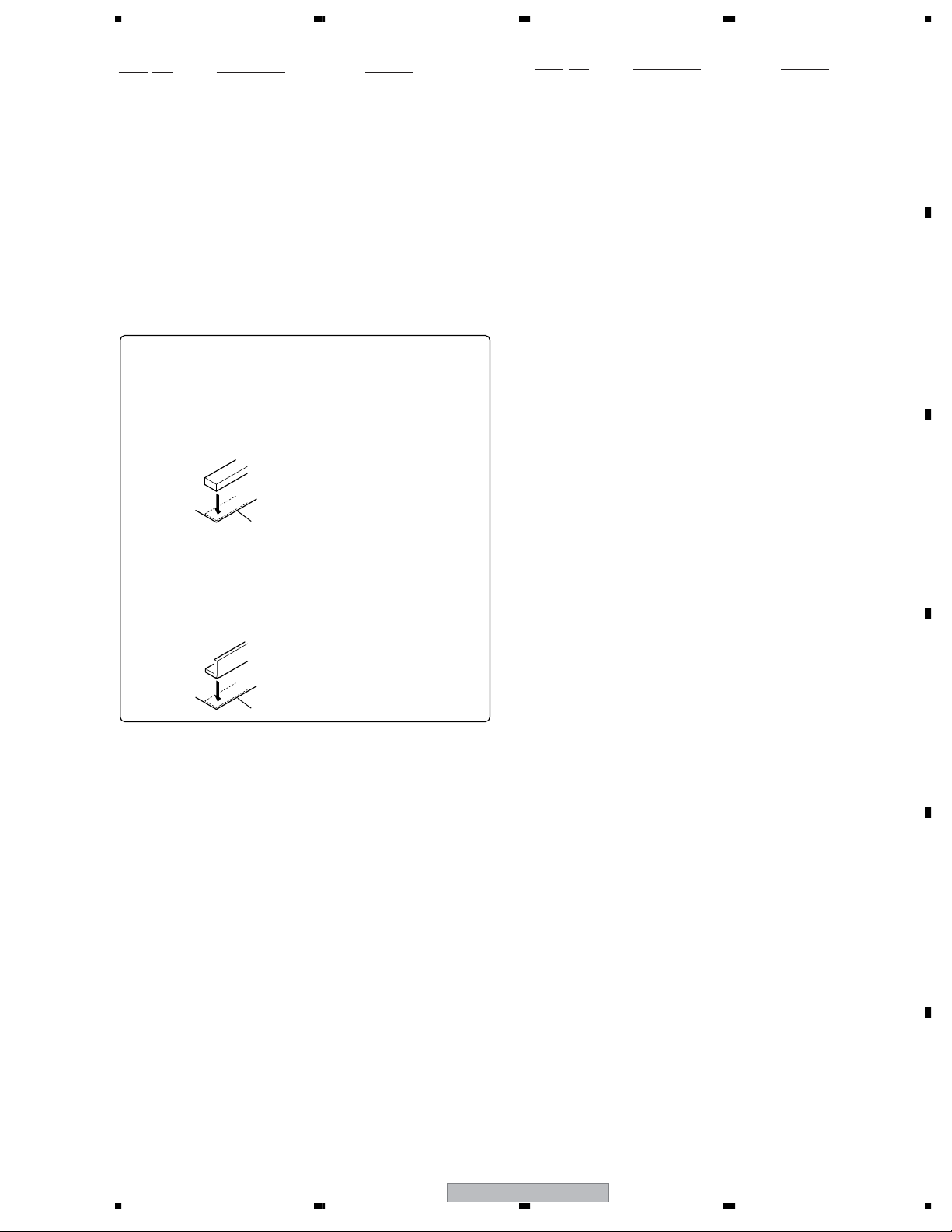
Note ∗3: Notes on locations where gaskets are adhered
At the locations where gaskets are to be adhered on each part,
engraved marks are provided.
(a) Rectangular gaskets
Adhere a rectangular gasket by aligning it with the engraved
corner marks. If no marks are provided on the part, adhere the
gasket aligned with the four corners of the part.
No. Description Part No.
Mark
11 Gasket ICR1 DEC2740
12 Gasket RB DEC2742
13 Gasket ICR2 DEC2800
14 Gasket C3 DEC2801
NSP 15 Side Cover DNE1503
16 Binder ZCA-SKB90BK
17 Screw BBZ30P060FMC
18 Screw BMZ40P080FZK
19 Screw DBA1258
A
B
Engraved mark
(b) L-shaped gaskets
Adhere an L-shaped gasket by aligning the outer corner of the
gasket with the engraved mark on the part. In cases of the
chassis and side covers, adhere the gasket by aligning both ends
of the gasket with the two engraved marks. If no marks are
provided on the part, adhere the gasket by referring to the
corresponding "Exploded views".
Engraved mark
C
D
E
56
PRV-LX10
F
17
7
8
1234
X (EU)
X (EU)
X (EU)
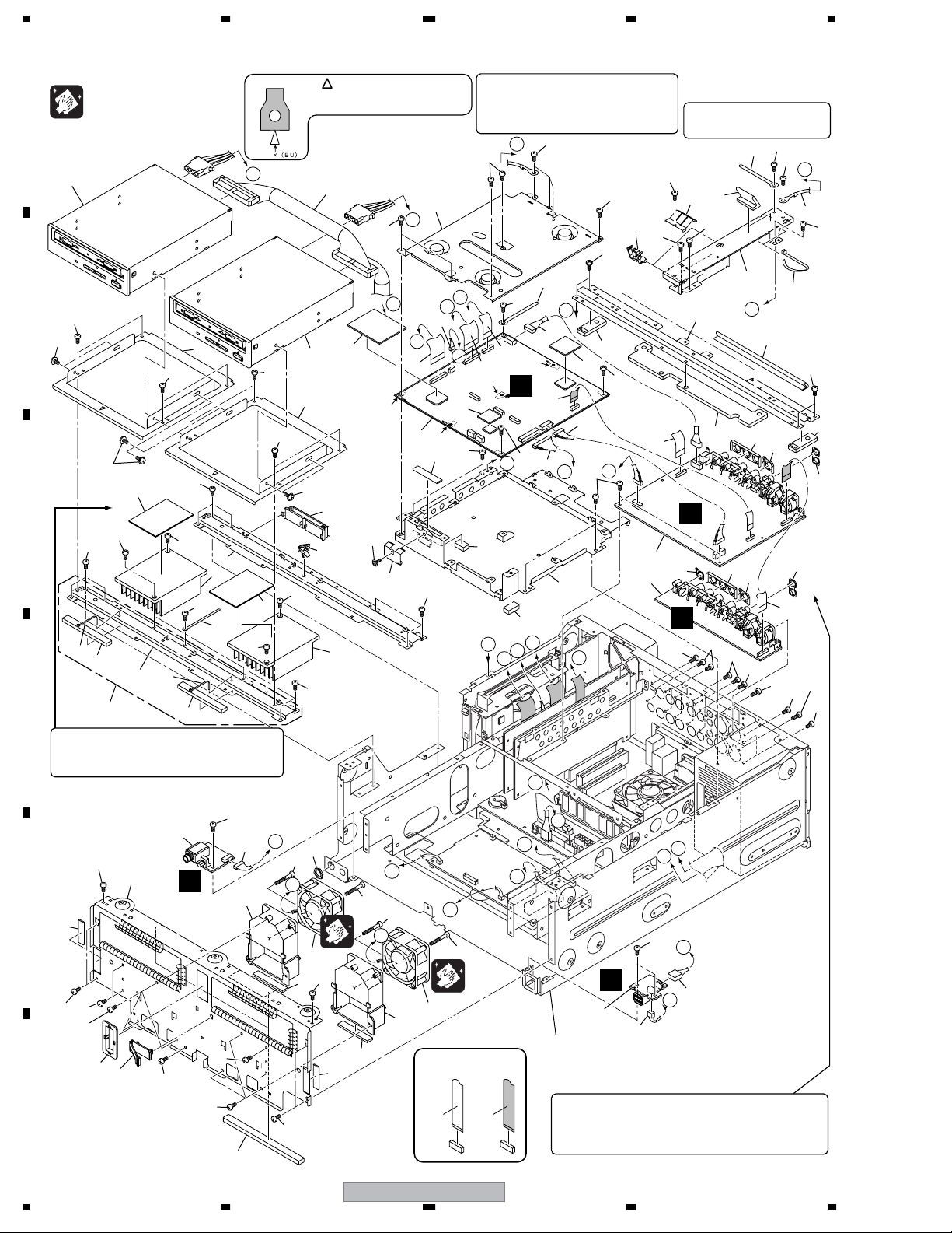
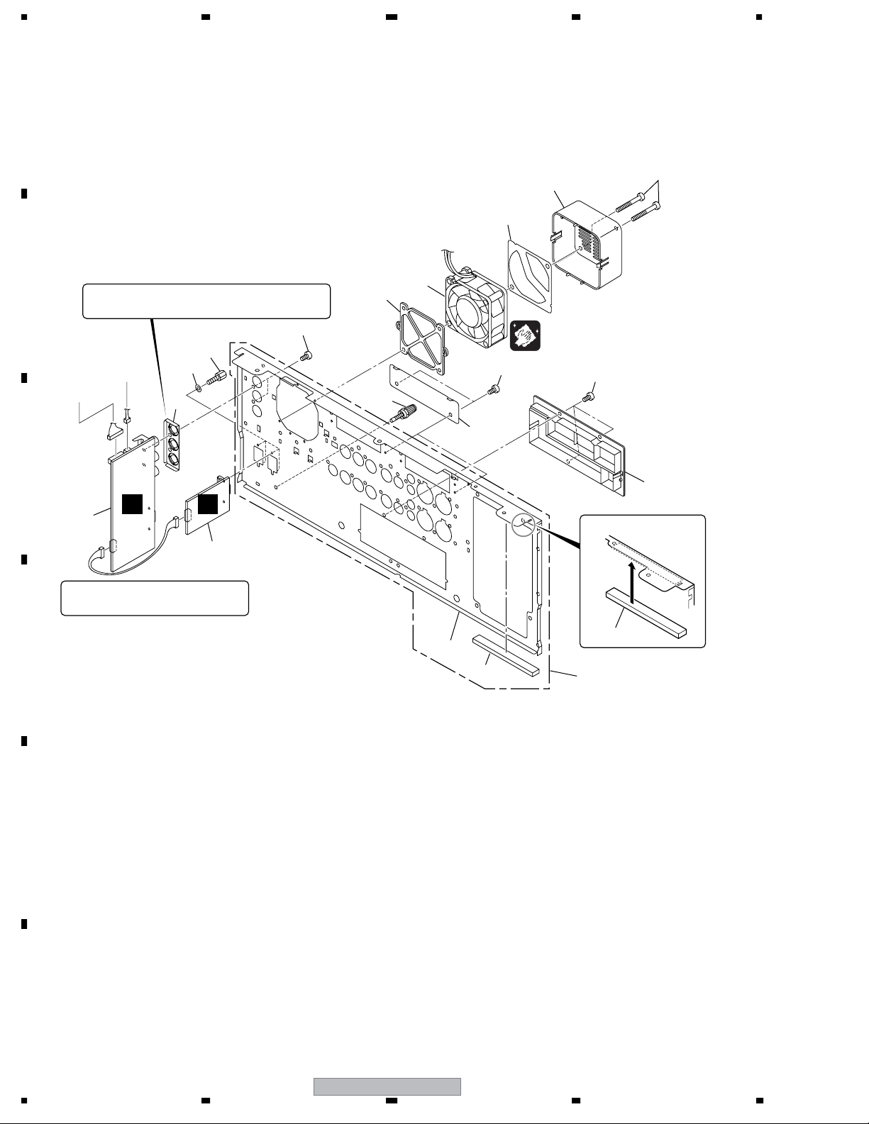
2.3 EXTERIOR SECTION (2/3)
FAN Cleaning
A
Cleaning paper (GED-008)
To ATX POWER
SUPPLY UNIT
6
B
35
36
7
35
36
11
35
∗1
35
C
35
35
35
56
57
D
Note ∗1:
When disassembling/reassembling No. 6 Drive
Assy LX1, make sure that No. 11 Silicone spacer A
is not torn or damaged. If it is, replace with a new one.
58
14
56
57
12
14
13
Note ∗5:
H
11
35
The " x (EU)" mark part and AVI shield
which are printed by AVIB Assy are fixed
with a screw. (Four places)
To ATX POWER
66
SUPPLY UNIT
35
G
42
6
35
7
35
36
8
9
35
35
∗5
59
47
12
Note ∗4:
Attach the earth spring AVIB (CU) after the AVI
base EU, AVI shield EU, and AVIB Assy have
been assembled but before they are
reassembled into the unit.
35
P
35
15
O
35
61
Note ∗3:
See "note ∗3" on the section
"2.2 EXTERIOR SECTION (1/3)".
35
35
50
∗3
34
35
10
35
35
P
55
35
35
51
49
43
N
33
∗3
35
45
∗2∗2
46
48
52
10
M
L
21
J
20
E
U
)
∗3
K
X
(
16
X
(
E
U
)
1
∗5
35
44
20
∗5
19
35
A
17
22
41
24
48
35
To DECB
(CN1811)
X
(
E
U
)
∗5
H
23
68
35
N
67
I
F
35
∗2
A
∗4
35
63
18
62
L
A
K
J
M
G
2
∗2
53
3
45
46
∗2
52
∗2
25
E
39
65
39
38
40
39
40
39
4
35
28
E
∗3
D
64
26
32
I
27
37
B
B
37
37
C
C
37
54
31
35
∗3
35
35
35
38
29
30
35
F
35
38
∗3
54
64
∗3
35
60
18
31
32
NON-CONTACT
PRV-LX10
SIDE
CONTACT SIDE
E
F
O
H
D
35
E
N
5
Refer to
"2.4 EXTERIOR SECTION (3/3)"
"2.5 REAR PANEL SECTION".
Note ∗2:
When replacing JKIB Assy or JKOB Assy, be sure to remove 3P
BNC earth plate, BNC earth plate, 2P earth plate and 1P earth
plate (only JKOB Assy) from the old Assy and attach them to the
new Assy.
70
69
D
1234

5678
Mark No. Description Part No.
1AVIB Assy DWV1202
2 JKIB Assy DWZ1126
3JKOB Assy DWZ1127
4 HPVB Assy DWZ1128
5 USBB Assy DWZ1159
> 6 DRIVE Assy LX1 DXX2532
NSP 7 Drive Base DNH2548
8 Flat Cable Clamp DEC2534
NSP 9 Wire Saddle DEC2543
10 Cord Holder RNH-184
11 Silicone Spacer A DEB1600
12 Heat Sink DNG1087
13 Cord Holder RNH1005
NSP 14 Front Bridge DNE1525
NSP 15 AVI Shield DNE1505
16 Radiation Sheet L VEB1332
NSP 17 Rear Bridge EU DNE1526
NSP 18 AVI Base EU DNE1504
19 Flexible Cable (30P) DDD1229
20 Flexible Cable (50P) DDD1226
21 Connector Assy 4P DKP3640
22 Housing Assy 6P DKP3658
23 Flexible Cable (20P) DDD1228
24 Connector Assy 7P DKP3639
25 Flexible Cable (30P) DDD1230
26 Connector Assy 8P DKP3643
27 Nut NKX2FUC
NSP 28 Panel Stay Assy DNE1501
NSP 29 Protector DNK1340
30 Flat Cable Clamp DEC1850
> 31 DC Fan Motor AXM7014
NSP 32 Fan Duct EU DNK4447
33 Gasket RB DEC2742
34 Gasket FC DEC2802
35 Screw BBZ30P060FMC
36 Screw AMZ30P060FZK
37 Screw BPZ30P350FZK
38 Screw BPZ30P080FZK
39 Screw BBT30P060FZK
40 Screw PPZ30P100FMC
41 EMC Sheet S DEB1624
42 EMC Sheet DEB1620
43 Binder DEC2803
44 Gasket AVI DEC2747
45 3P BNC Earth Plate (CU) DBK1273
46 BNC Earth Plate (CU) DBK1274
47 Earth Spring AVIB (CU) DBK1275
48 Cover Sheet BR DEC2834
NSP 49 Flexible Cover DNE1506
50 FC Earth Metal (CU) DBK1278
Mark No. Description Part No.
51 Cover Sheet BC DEC2833
52 2P Earth Plate ANK1156
53 1P Earth Plate ANK1228
54 Gasket Fan DEC2741
NSP 55 Earth Lead Jumper DE006VD0
56 Binder ZCA-SKB90BK
57 Gasket C1 DEC2745
58 Front Bridge Assy DXA2031
59 Screw AMZ30P060FMC
60 Cover Sheet FC DEC2837
61 Locking Wire Saddle DEC1305
62 Cover Sheet AV1 DEC2835
63 Cover Sheet AV2 DEC2836
64 Gasket PS DEC2744
65 Screw BCZ30P060FNI
66 Connector 40P DKP3671
67 Connector 14P DKP3636
68 Flexible Cable 30P DDD1229
69 Connector 10P DKP3646
70 Connector 3P DKP3655
A
B
C
D
E
F
56
PRV-LX10
19
7
8
1234
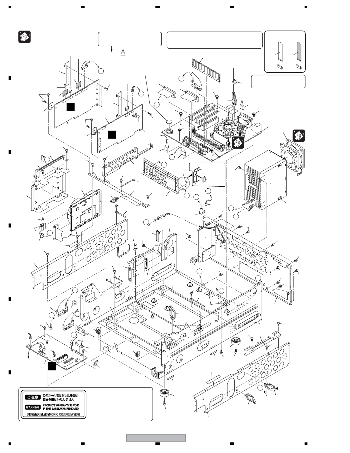
2.4 EXTERIOR SECTION (3/3)
FAN Cleaning
A
B
C
D
Cleaning paper (GED-008)
To AVIB
(CN3002)
13
To Drive
Assy
46
47
47
26
17
60
7
12
B
F
46
To AVIB
(CN3301)
6
1
46
16
60
G
To AVIB
(CN3001)
14
E
46
46
D
37
G
38
46
To Fan
(Left)
To FLKB
(CN501)
40
46
3
To Fan
(Right)
I
E
56
I
C
Note ∗1:
Be careful of sharp edges while working
around this section.
H
To AVIB
(CN6002)
46
6
2
To JKIB
(CN7801)
46
11
26
∗3
57
To USSB
(CN684)
41
46
F
46
46
34
∗2
30
15
43
7
46
53
42
To AVIB
(CN3201)
39
46
Lithium Battery (3.0V)
PANASONIC : CR2032
SONY : CR2032
TOSHIBA : CR2032
MAXELL : CR2032
J
46
To USBB
(CN681)
8
10
9
46
15
G
28
57
28
54
∗3
56
29 48
53
42
Note ∗4:
The Memory, CPU and CPU Cooler are provided together as
the components of the MOTHER BOARD Assy (DXF1007)
service parts.
∗4
To ATX Power
Supply Unit
49
20
D
49
19
21
E
∗4
49
22
C
23
K
55
Note: Gasket locations
59
Main chassis EU
L
H
Terminal cover
Assy
∗1
25
27
50
B
32
∗3
31
36
57
33
K
46
10
Gasket S
J
53
26
24
53
49
50
46
A
44
46
46
F
51
To FLKB
(CN504)
26
I
46
NON-CONTACT
SIDE
Note ∗3:
See "note ∗3" on the section
"2.2 EXTERIOR SECTION (1/3)".
18
49
∗4
4
52
5
50
46
50
L
57
58
45
46
48
Refer to
"2.5 REAR PANEL
SECTION".
∗3
46
46
CONTACT SIDE
48
50
51
53
44
A
36
36
17
Note ∗2:
When the HDD is removed, order No.30 Label
(for service) and attach it to cover the hole for
the screw.
The label is a tamper-evident seal. The printing
F
20
1234
on the label stuck on the product is in black,
but that on the label for service is in orange.
PRV-LX10

5678
Mark No. Description Part No.
1 PCIB Assy DWP1080
2 DECB Assy DWP1081
3 PWRB (POLY) Assy DWZ1129
> 4MOTHER BOARD Assy DXF1007
> 5ATX Power Supply Unit DXF1005
NSP 6 Board Stay R DNF1677
NSP 7 Board Stay F DNF1679
NSP 8 PCI Cover DNE1449
NSP 9 Center Stay DNE1444
10 Cord Holder RNH1005
11 Locking Wire Saddle DEC1717
NSP 12 HDD Handle DNE1450
NSP 13 HDD Base DNH2549
> 14 HDD 120G 4R120L0 VXF1016
15 Cord Holder RNH-184
16 Edge Sheet DEC2567
NSP 17 FR Plate DND1246
18 Connector Assy 10P-3P DKP3645
19 Connector Assy 4P DKP3656
20 Connector Assy 40P DKP3671
21 Connector Assy 40P DKP3647
22 Connector Assy 10P DKP3646
23 Connector Assy 9P-6P DKP3635
24 Connector Assy 2P DKP3638
25 Connector Assy 11P DKP3642
26 Binder ZCA-SKB90BK
NSP 27 Main Chassis EU DNA1312
NSP 28 PCB Support VEC1267
29 Card Spacer QEC1012
30 Label (for service) BAX1238
NSP 31 Label VRW-348
32 Lithium Battery Caution Label DRW2162
33 Connector Assy 6P DKP3644
34 Edge Guard A DEC2566
NSP 35 Wire Saddle DEC2543
NSP 36 Wire Saddle (8S) DEC1760
37 Connector Assy 20P DKP3657
38 Connector Assy 2P DKP3736
39 Connector Assy 14P DKP3636
40 Connector Assy 20P DKP3637
41 Connector Assy 3P DKP3655
NSP 42 Card Edge Spacer DEC1211
43 Screw Guard DEB1447
44 Leg DEC2583
NSP 45 Jack Stay DNE1446
46 Screw BBZ30P060FMC
47 Screw DBA1125
48 Screw AMZ30P060FZK
49 Screw BMP30P060FNI
50 Screw BBT30P060FZK
Mark No. Description Part No.
51 Screw BBZ30P100FMC
> 52 DC Fan Motor DZM1001
53 Driver Sheet Assy VEC2242
54 Caution Label (EU) DRW2214
NSP 55 Terminal Cover Assy DNE1539
56 Cover Sheet FR DEC2838
57 Gasket C1 DEC2745
58 Gasket C2 DEC2746
59 Gasket S DEC2855
60 Flexible Cable 50P DDD1226
A
B
C
D
E
F
56
PRV-LX10
21
7
8
1234
2.5 REAR PANEL SECTION
A
To PWRB
(CN9)
13
(Torque : 0.65 N•m)
11
12
B
Note:
When replacing the JKDB Assy, be sure to remove the 3P BNC
earth plate (CU) from the old Assy and attach it to the new Assy.
14
15
To PCIB
(
CN2102
To DECB
(
CN1471
)
)
19
16
10
9
FAN Cleaning
Cleaning paper (GED-008)
14
20
7
6
C
5
B
1
C
Note: Gasket locations
2
Note:
When removing the JKDB Assy or 4221B Assy,
be sure to remove the rear panel first.
Gasket RP
D
4
17
18
E
F
22
PRV-LX10
1234

5678
REAR PANEL SECTIN Parts List
Mark No. Description Part No.
1 JKDB Assy DWZ1134
2 422IB Assy DWZ1133
3• • • • •
NSP 4 Rear Panel DNC1703
NSP 5 Terminal Cover DNK4154
NSP 6 Blind Plate DNF1678
7 Earth Terminal DKE-102
NSP 8 Guard Tape DEC2587
9Fan Spacer AMR7265
> 10 DC Fan Motor AXM7014
11 Fan Cover AMR7264
12 Fan Plate DEC2692
13 Screw ABA7003
14 Screw BBT30P060FZK
15 Screw BBA1051
16 3P BNC Earth Plate (CU) DBK1273
17 Gasket RP DEC2743
18 Rear Panel Assy DXA2022
19 Washer WH30FNI
20 Screw BBZ30P060FMC
A
B
C
D
E
F
56
PRV-LX10
23
7
8
1234
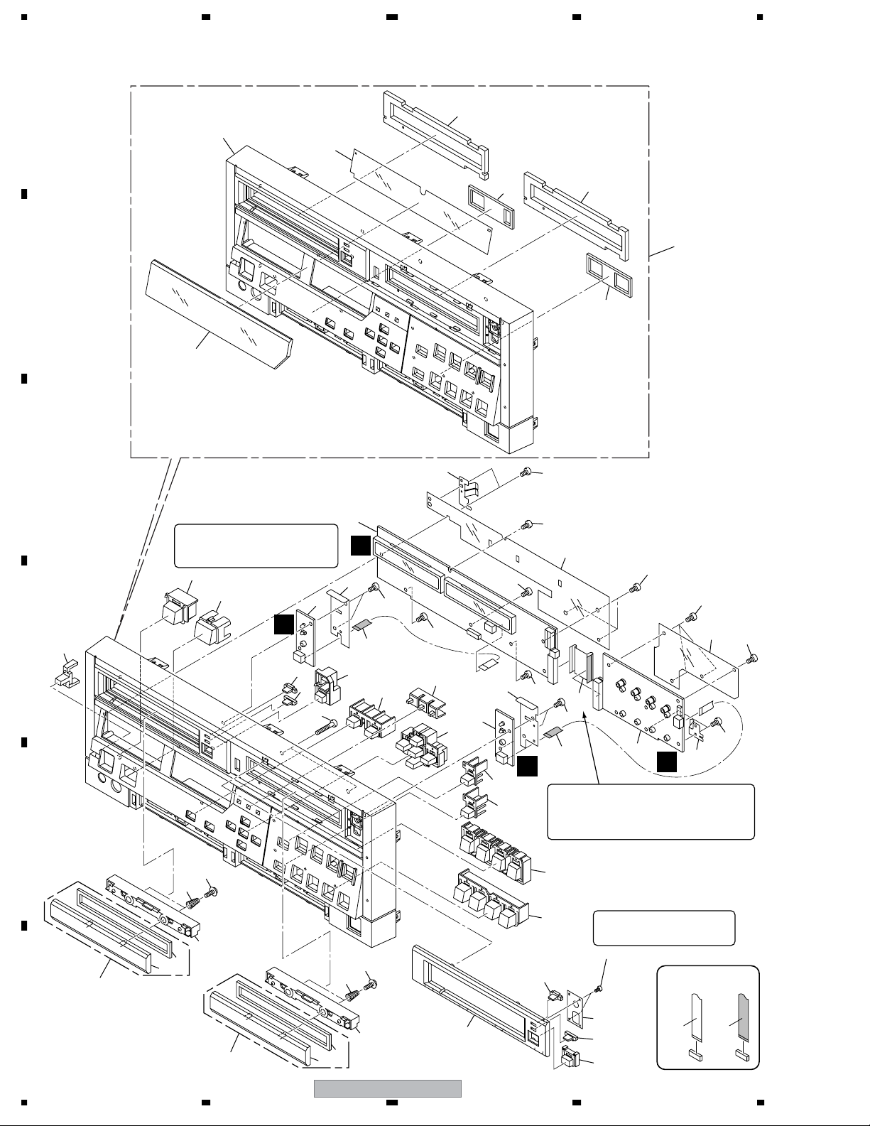
2.6 FRONT PANEL SECTION
A
7
10
B
6
C
45
11
8
11
5
9
36
37
1
J
43
2
16
22
35
23
24
36
36
25
∗1
26
44
3
27
28
Note ∗1:
This part must be placed with the correct
side facing up. Be careful of the direction
during attachment.
19
20
∗1
L
18
D
21
21
E
35
16
15
14
13
12
36
36
32
36
∗2
36
34
36
23
M
Note ∗2:
for lead dressing: Do NOT bend the flexible cable at
points very near the reinforcing plates that are
provided at the two ends of the flexible cable.
Such bending may lead to breakage of the cable.
29
30
21
4
K
Note:
For this screw, use a medium-sized
Phillips screwdriver.
46
31
36
33
36
36
F
42
24
15
38
39
14
PRV-LX10
1234
41
21
40
NON-CONTACT
SIDE
CONTACT SIDE

5678
Mark No. Description Part No.
1 FLKB(WYV/RB) Assy DWZ1164
2DRV1B Assy DWZ1160
3DRV2B Assy DWZ1161
4 KEYB(WYV/RB) Assy DWZ1157
5Front Panel EU Assy DXA2023
NSP 6 FL Window DAK1001or DEC2849
NSP 7 Front Panel EU DAX1014
NSP 8 Air Seal A DED1164
NSP 9 Air Seal B DED1165
NSP 10 FL Filter DEC2531
11 Drive Filter DED1163
12 Tray Panel 1 Assy DXA1961
NSP 13 Tray Panel 1 DNV1037
NSP 14 Tray Filter DEC2528
15 Tray Holder DNV1038
16 Tray Spring DBH1515
17 • • • • •
18 Power Lens DNV1043
19 Power Button DAC2105
20 IR Window DNV1042
21 Drive Lens DNV1039
22 Tray Button 1 DAC2099
23 Flexible Cable (6P) DDD1231
24 ETC Button DAC2103
25 Drive Select Lens DNV1041
26 Cursor Button DAC2104
27 Drive Select Button DAC2102
28 Preview Button DAC2107
29 Play Button 1 DAC2100
30 Play Button 2 DAC2101
31 Earth Metal B (CU) DBK1277
32 Barrier FL DEC2748
33 Barrier 2 DEC2533
34 Flexible Cable (25P) DDD1232
35 Screw VBA1034
36 Screw BPZ30P080FZK
37 Screw BPZ30P250FMC
38 Tray Panel 2 Assy DXA1962
NSP 39 Tray Panel 2 DNV1044
40 Tray Button 2 DAC2110
41 Drive Lens Support Plate DEC2536
42 Drive 2 Panel DNV1045
43 Barrier D1 DEC2765
44 Barrier D2 DEC2766
45 Earth Metal F (CU) DBK1276
46 Screw BPZ20P060FZK
A
B
C
D
E
F
56
PRV-LX10
25
7
8
1234
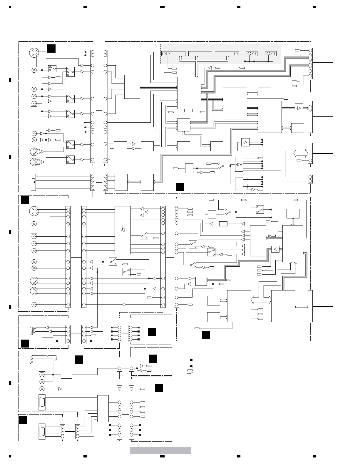
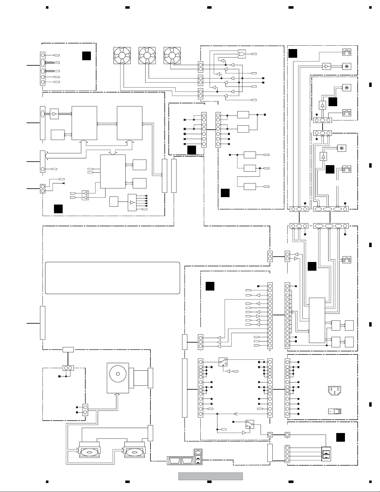
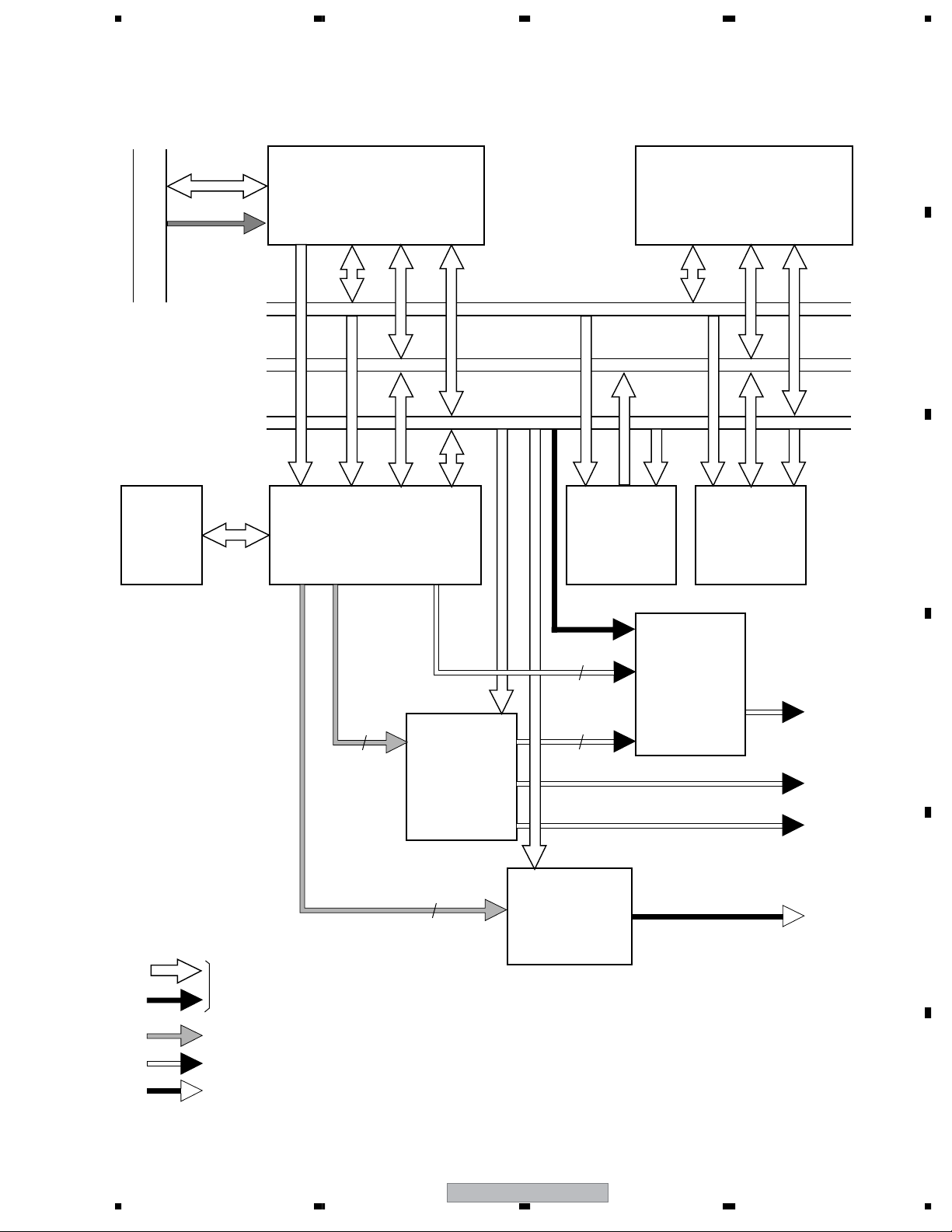
3. BLOCK DIAGRAM AND SCHEMATIC DIAGRAM
3.1 BLOCK DIAGRAM
3.1.1 OVERALL BLOCK DIAGRAM
A
B
C
D
E
F
JA7401
S IN
JA7402
CV IN
JA7403
Y IN
Cb IN
Cr IN
JA7601
L IN
R IN
JA7961
XLR
CH1/L
XLR
CH2/R
JA7404
DV I/O
JKOB ASSY
E
JA7852
S OUT
JA7853
CV OUT
JA7854
Y OUT
Cb OUT
Cr OUT
JA7851
L OUT
R OUT
JA7981
XLR
CH1/L
XLR
CH2/R
JA7855
SPDIF
OUT
JA661
HEAD
PHONE
OUT
HPVB ASSY
D
S7941
JA7941
EXSYNC
LTC IN
CN7901
REMOTE OUT
422IB ASSY
C
CN7951
REMOTE IN
CN7611
CB IN
CR IN
XTPB
XTPA
19
17
15
21
23
25
11
9
3
1
7
5
29
2
4
5
7
CIN
TPB
TPA
CN7402
CN3501
(20P)
3
4
12
14
10
8
2
5
6
19
17
CN4001
(6P)
2
3
4
5
COMPONENT-Y
COMPONENT-Cb
COMPONENT-Cr
TC4W53FU
MUTE
+5V
(20P)
18
17
11
13
19
15
16
(6P)
C-DCC-DC
IC7702
9
7
2
4
2
3
4
5
CV
+9V
+5V
+9V
Y
C
1
TC4W53FU
-9V
IC3801
TC9412A
4
EVolume
21
IC4002
TSB41AB2PAP
34
35
36
37
28
31
30
33
25
23
21
IC7705
CN7613
(7P)
122
135
118
120
DV
Phy
IC7803
LA73054
6dB
7
Thru
6
1
1
3
5
7
IC3501
PD0272
VIDEO
ADC
George
3221
DV I/O
1-13
19 82-96
3
4
13
8
6
2
11
14
16
7
6
CN3202
(7P)
1
3
5
7
SQZ
LTR
P/I
Y
C
CV
COMPONENT-Y
COMPONENT-Cb
COMPONENT-Cr
12,53-63
IC3802
PCM1800-A
AUDIO
ADC
5
IC4001
TSB42AB4PDT
77
DV
Link
IC7802
TC4W53FU
1
Thru
MUTE
AVIB ASSY (2/3)
+9V
+5V
+9V
-9V
JKIB ASSY
C
Y
A
IC7409
MM1117XF
3
1
Thru
7
VIDEO SEL2
VIDEO SEL1
IC7414
MM1117XF
5
137
VIDEO Y IN
Beta
SMPTE
IC7418
MM1117XF
Beta
1
3
IC7423
MM1117XF
1
3
7
7
SMPTE
Beta
SMPTE
Beta/SMPTE SEL
AUDIO SEL
Thru
Thru
1
2
3
4
CV OUT
L OUT
R OUT
COLD
COLD
SPDIF OUT
IC661
BH3544F
1
7
HP_R
3
HP_L
5
MUTE
2
+5V
CN7851
Y
C
HOT
HOT
CN661
TC4W53FU
7
6
TC4W53FU
7
6
(30P)
(8P)
Thru
IC7614
1
AUDIO IN L
IC7618
1
AUDIO IN R
CN7802
(30P)
12
14
18 13
16
10
8
6
20
22
28
30
24
26
2
CN7701
2
4
5
7
(8P)
DECB ASSY (3/3)
CN1471
2
7
3
8
2
7
3
8
422-OUT
422+OUT
422+IN
422-IN
IC7941
LM1881M
2
CN7952
(6P)
1
2
3
4
SYNC
SEP
B
1
CN7903
(6P)
1
2
3
4
JKDB ASSY
10
9
11
12
13
14
16
15
IC7901
DS8922M
422
DRV
+12V
-12V
CN7941
(2P)
(2P)
1
1
CN2102
CN7902
(11P)
(11P)
1
1
LTC
PCIB ASSY(2/2)
8
7
7
7
8
1
9
2
10
5
+5V
2
4
422RXDOUT
8
422TXDOUT
9
422RXDIN
10
422TXDIN
5
+5V
2
+12V
4
-12V
OPTIONAL CONNECTOR
CN5501(30P) CN5502(26P) CN5503(30P)
29 27
27MSDI
27MOPB
IC5004
14
XC2S50-5PQ
10
656(ANALOG)
15- 24
5
27
7
29-31
33-35
LTC
PE7004A
127-129
132-137
CS8420-CSZD1
12-14
13-15
16-18
PCO
1-9
20,23
CN7801
(30P)
7
Thru
6
H
CN1811
(30P)
28
3
26
5
27
4
19
12
21
10
23
8
15
16
13
18
11
20
8
23
25
6
21
10
3
28
185
81-89
LTC_SW
68-70
168-180
Xilinx
94
7
IC6003
27MSDO
28-30
AUDIO
I/F
19-24
Aprilia
84-120
IC6004
SRC
DV I/O
X3301
27MSDI
27MHz
13 7
VCXO
VSS1146
AVIB ASSY (1/3)
SQZ
LTR
P/XI
Y
C
CV
IC1851
SN74AHC2G53
AOUTR
SN74AHC2G53
AOUTL
1
1
IC1853
PCM1718E
16
13
SPDIF
7
6
7
6
IC1751
AUDIO
XSYNCIN
H
F
CSYNC
XSYNCIN
Power (with no specifically designated destination)
Signal (with no specifically designated destination)
Signal (to the destination with the same name within the same Assy)
G
656(ANALOG)
DV OUT
IC6002
uPD61003
3,7,16
DDCE
17,44-68
Audery
IC3306
SN74AHC
6
27MOPB
DVCLK
CY2081SL
27MHz
3
6
PLL
DSS1117
13.824MHz
PRGA_Y
7
1
6
IC1852
SN74AHC2G53
PRGA_R
1-3
DAC
21
IC1611
K4S643232H
SDRAM
64M
IC1612
PD6454C8
FLASH
32M
DECB ASSY (1/3)
F
27MDEC
PD6342A
44-54
TBC/DNR
156-165
1
36MDEC
IC1417
SN74AHC2G53
6
7
X1411
VCXO
PRGA_B
XMUTE
HD6417709AF100B
199
29
+5V
IC5002
117-126
55-64
Vaik ilt
DV I/O
IC3309
PLL1700E
6
PLL
IC1411
BU2288FVIC1412
1
8
AV1 AUDIO DATA
IC1211
MPU
SH3
CN3203(4P)
2 3
27MSDO
131
656
(ANALOG)
(DV IN)
DV I/O
17
13
9
PLL
SN74AHC2G53
AD7172KST
33
29
35
28
25
24
AV1 AUDIO DATA
PRGA_Y
PRGA_B
PRGA_R
112
119
185
M2V64S50DTP
IC1418
6
7
AV1CKV
IC1711
2-14,48
VIDEO
ENCODER
MPU BUS
CN3204(4P)
2 3
IC5001
SDRAM
64M
IC7004
DVXCEL-B A1
DV CODEC
MPEG VIDEO
ENCODER
DVxcel
40MGEO
40MPLD
40MAPR
27MAV1
27MDVX
27MVAI
27MFPGA
27MAUD
18MSRC
18MA/D
18MAUD
36MFPGA
36MAPR
36MDEC
1
SQZ
LTR
P/XI
36MCLK
27MCLK
AV1
VIDEO DATA
168-181
XC2S100PQ208
INTERFACE
27MDEC
36MDEC
27MAV1
BitStream
CSYNC
183
177
180-192
159-176
119
116
122
IC1311
PCI
Xilinx
AV1 VIDEO DATA
AV1 AUDIO DATA
PCO
IC7002
IC7003
SDRAM
64MX2
W986432DH
MPU BUS
LTC
IC1512
K4S641632F
SDRAM
64M
53-102
IC1513
M65776AFP
MPEG
DECODER
2,4,201-208
AV1
BitStream
3-59
185-206
CN6002
(30P)
27
11-2 6
6-8
2
29
CN3002
(50P)
2-12
CN3001
(50P)
49
CN3301
(4P)
2
4
178
PCI I/F
26
PRV-LX10
1234
5678
CN1651
DECB ASSY(2/3)
(30P)
27
11-2 6
6-8
2
29
CN2103
(50P)
2-12
IC2003
HY57V641620HGT
SDRAM
64M
CN2104
(50P)
49
CN2101
(4P)
2
4
422RXDOUT
422RXDIN
G
DTCLK
AV1 VIDEO DATA
AV1 AUDIO DATA
F
36MDEC
DVCLK
IC2001
422TXDOUT
422TXDIN
CLK40AVI
CLK27S
PD5219A
DMA
CONTROL
Slarom
IC2401
TC74VHC125
9
BitStream
MPU BUS
LTC
PCIB ASSY(1/2)
11812
167-181
Not Use
IC2405
HD6417709AF100B
166
MPU
164
172
SH3
171
X2401
40MHz
XTL
DSS1101
IC2309
XC2S100-5PQ208C
PCI
INTERFACE
Xilinx
K4S643232H
SDRAM
PD6453C8
IC2403
32-8
TC74LCX541
IC2404
64M
IC2406
FLASH
32M
18
17
16
15
14
13
3-59
185-206
CLK40H
CLK40D
CLK40P
CLK40C
CLK40S
CLK40AVI
FAN (REAR)FAN (DRV1)FAN (DRV2)
AVIB ASSY
(3/3)
+2.5V
+3.3V
+5V
-12V
+12V
PCI I/F
PCI SLOT3
(124P)
CN9 (2P)
CN10 (2P)
CN11 (2P)
H
1
2
1
2
1
2
CN3201
(14P)
3
4
7
8
10
12
13
FAN_DET
FAN_CONT1
+12V
-12V
FAN_CONT2
FAN_CONT3
CN2
(14P)
10
12
13
3
4
7
8
+12V
+5V
-12V
+12V
2-3
2-3
IC101
BP5232-25A
REG
IC201
BP5233-33A
REG
AN8015SH
6
AN8015SH
6
BA9743AFV
6
IC451
REG
IC401
REG
IC301
REG
9-11
+5V
9-11
5
5
7
I
PWRB (POLY) ASSY (2/2)
V-31V
V-28V
V-24V
CN631(6P)
CN502(6P)
L
4
DRV1B
ASSY
V+5V
5
1-3
23
4-6
DRV1 OPEN/CLOSE
DRV2B
ASSY
V+5V
5
1-3
2
4-6
V+5V
K
KEYB
(WYV/RB)
ASSY
13-1620-23
M
4
CN641(6P)
CN602(6P)
3
S631
D631,D632
LED
• DISC IN
• ACCESS
D641,D642
LED
• DISC IN
• ACCESS
S641
DRV2
OPEN/CLOSE
D603,D606
D608,D611
LED
S601-S610
KEY
• RSTEP
• FSTEP
• NR/KR
• NF/KF
• DRV SEL
• PREVIEW
• REC
• PLAY
• PAUSE
• STOP
V+5V
210-13 14-203-6
CN601(25P)
CN503(25P)
6-12 24
• REC
• PLAY
• PAUSE
• STOP
A
B
C
MOTHER BOARD ASSY
Notes:
• Replace the whole MOTHER BOARD Assy. No part in the
MOTHER BOARD Assy is provided as a repair part.
• A schematic diagram is not provided, because no repair
part is provided.
(124P)
PCI SLOT2
(4P)
P4
3 4
+12V
(4P)
ATX POWER
SUPPLY UNIT
(2/2)
+12V
+5V
120GB HDD
MASTER
(4P)
(4P)
1
4
(40P)
IDE 1
(40P)
IDE 2
MASTER
(4P) (4P)
DRIVE1
SLAVE
DRIVE2
56
UPS
(9P)
(9P)
(20P)
FPIOATX POWER
VGA
(15P)
PWRB (POLY) ASSY (1/2)
I
CN6
(6P)
HDD_LED
1
RESET
5
PWR_SW
3
CN4
(20P)
9
4
6
19
20
18
1
2
11
10
12
14
8
Ethernet(15P)
REAR USB(4Px2)
RY1
BSR1014
4
+5V
-5V
+3.3V
+12V
-12V
PS_ON_O#
FAN_CONT1
FAN_CONT2
FAN_CONT2
1
+5V
PWR OK
FAN_DET
PWR OK
PS_ON_I#
PS_ON_O#
PWR_SW#
5
+5VSB
V-24V
V-28V
V-31V
PWR_SW#
PS_ON_I#
BSR1014
5
PRV-LX10
+5VSB
+3.3V
+12V
-12V
RY2
1
7
+5V
V+5V
CN504
(10P)
COM2
(3P)
2
SIN
3
23
SOUT
J
CN3
CN501
(20P)
(20P)
3
3
4
4
6
6
7
7
8
8
9
9
10
10
12
12
14
14
16
16
18
18
19
19
13
13
15
15
17
17
CN1
(20P)
-5V
4
CN5
(3P)
(10P)
19
20
18
11
10
12
14
9
4
6
1
2
8
3
USB2
9
4
6
19
20
18
1
2
11
10
12
14
8
CN684
(3P)
3
CN681
(10P)
3
4
5
6
FLKB
(WYV/RB)
ASSY
V+5V
uPD78F0058GC
5,38
50,51
9
8
V-24V
V-28V
V-31V
(20P)
+5VSB
+5V
ATX POWER
SUPPLY UNIT (1/2)
-5V
+3.3V
+12V
-12V
PS ON#
PWR OK
+5V
-D_USB1
-D_USB2
+D_USB1
+D_USB2
IC501
uCOM
6,40
53,54
37,39
43,52
FL
11-14
15-18
2
6
3
7
V+5V
S501-S507
KEY
• UP
• DOWN
• RIGHT
• LEFT
• ENTER
• SETUP
• DISPLAY
IC502
V501
PT6315
DAW1019
6-9
FL
FL
DRV
TUBE
IC503
V502
PT6315
DAW1019
6-9
FL
FL
DRV
TUBE
AC IN
MAIN POWER
USBB ASSY
N
1,5
JA681
FRONT USB
D
E
F
27
8

1234
3.1.2 I/O BLOCK
A
JA7401
JA7402
JA7403
B
JA7601
C
Y
CV
Y
Cb
Cr
L
6dB
AMP
Thru
AMP(Beta)
AMP(SMPTE)
AMP(Beta)
AMP(SMPTE)
AMP(Beta)
AMP(SMPTE)
Thru
JKIB ASSY
A
CLAMP
AMP
AMP
AMP
V Select
Thru
A Select
Beta/SMPTE
2
S7941
JA7941
CN7611CN7402CN7801
CN7901
CN7951
B
Ex Sync
LTC
C
JKDB ASSY
SYNC
SEP.
COMP
AMP
422
DRV/RCV
CN7903
CN7952
422IB ASSY
CN7941CN7902
CN1471
F
CN2102
G
JA7961
XLR
CH1/L
XLR
CH2/R
JA7404
DV
R
AMP
AMP
C
Thru
H
H
CN3501
CN4001
D
JA7854
Y
Y/Cb/Cr
Cb
Cr
JA7852
Y/C
JA7853
JA7855
E
JA7851
JA7981
XLR
CH1/L
XLR
CH2/R
JA661
F
E
CV
SPDIF
CN7851
L
R
JKOB
ASSY
6dB
HPVB
D
ASSY
CN661
Y/Cb/Cr
Y/C
CV
CN7802
CN7701
28
IC7803
6dB
Thru
AMP
Thru
AMP
MUTE
PRV-LX10
AMP
MUTE
AMP
LTR/SQZ
P/I
Y/Cb/Cr
Y/C
CV
Thru
SPDIF
+5V
+9V
+9V
-9V
L
R
CN7613
F
H
CN1811
CN3202
1234
5678
3.1.3 DECB ASSY
A
PCI BUS
IC1512
64M
SDRAM
MPEG_
BITSTREAM
IC1311
PCI I/F
Xilinx FPGA
IC1513
MPEG Dec.
AV-1
SH-3_ADRS
SH-3_DATA
SH-3_CTRL
P/XI
IC1612
32M
FLASH
IC1211
MPU
SH-3
IC1611
64M
SDRAM
B
C
AV-1_VIDEO
: Digital Signal and Control Signal
: Digital AV Signal
: Analog Video Signal
: Analog Audio Signal
IC1711
VIDEO
Enc.
AV-1_AUDIO
Y/Pb/Pr
Y/Cb/Cr
IC1751
AUDIO
DAC
IC1851-IC1853
ANALOG
SW
Component
Composite
S-VIDEO (Y/C)
Audio (L/R)
D
E
F
56
PRV-LX10
29
7
8
1234
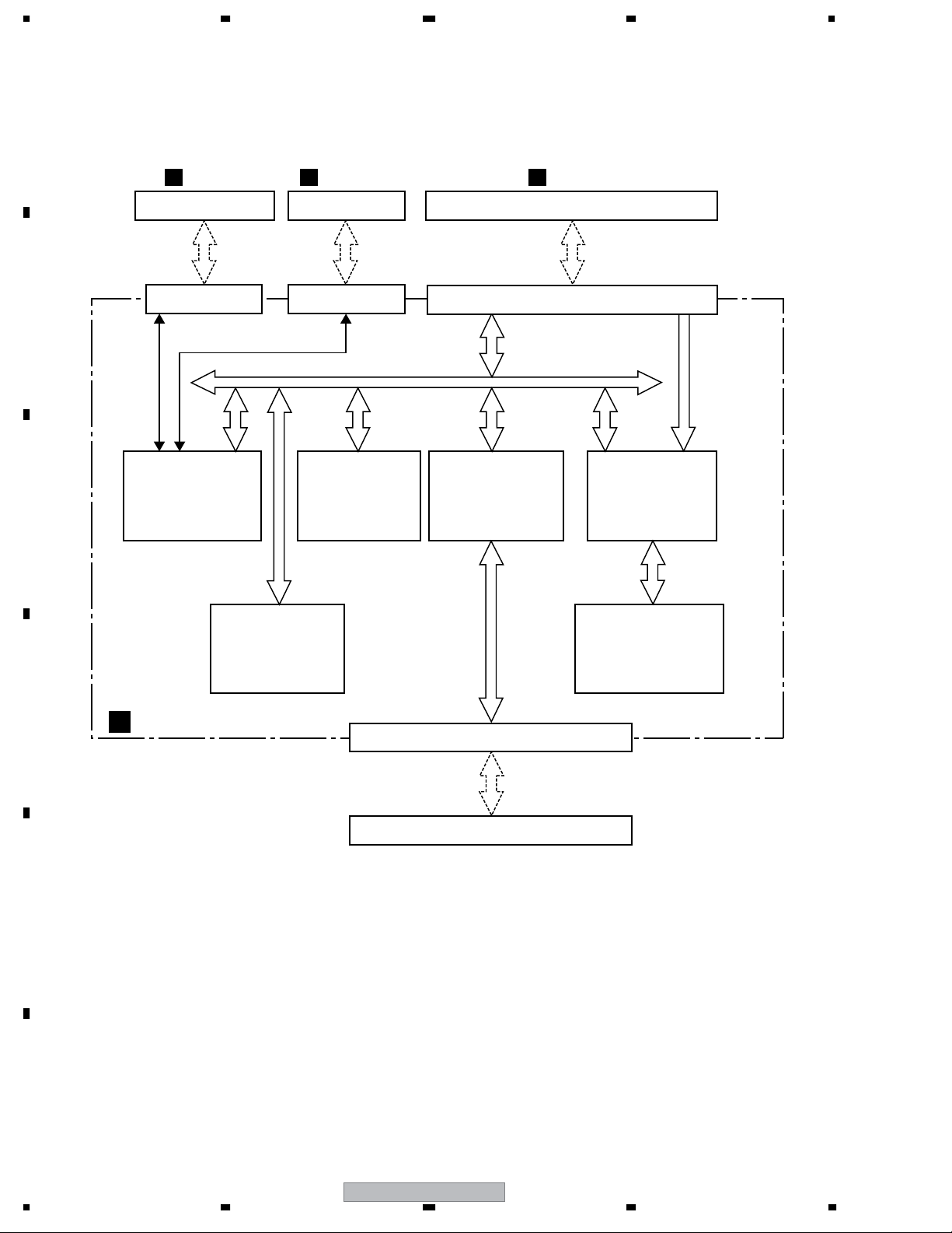
3.1.4 PCIB ASSY
A
JKDB ASSY
B
CN7902 (11 pin)
B
CN2102 (11 pin)
RS232C
RS422
IC2405
HD6417709AF100B
C
MPU
IC2404
DECB ASSY
F
CN1183 (7 pin)
CN2405 (7 pin)
MPU BUS
IC2406
PD6453C8
32M FLASH ROM
CN3301 (4 pin), CN3002 (50 pin), CN3001 (50 pin)
CN2101 (4 pin), CN2103 (50 pin), CN2104 (50 pin)
IC2309
XC2S100-5PQ208C
Pcif Xilinx
PCI BUS
K4S643232H-TC60
64M SDRAM
(Main Memory)
AVIB ASSY
H
MPEG
Stream
IC2001
PD5219
Slalom
(DMA Control,
CPU IF, etc.)
IC2003
HY57V641620HGT-7
64M SDRAM
(Stream Buffer)
D
PCIB ASSY
G
CN2301, CN2302 (PCI Card Edge: 124 pin)
MOTHER BOARD ASSY
E
F
30
PRV-LX10
1234
 Loading...