

Pioneer PRS-D4100F User Manual
Setting the Unit <ENGLISH>
Thank you for purchasing this PIONEER
product. Before attempting operation, be
sure to read this manual.
In case of trouble
When the unit does not operate properly,
contact your dealer or the nearest authorized PIONEER Service Station.
CAUTION
Never replace the fuse with one of greater
value or rating than the original fuse. Use
of an improper fuse could result in overheating and smoke and could cause damage to the product and injury including
burns.
CAUTION
Do NOT install or use your Pioneer amplifier by wiring speakers rated at 4 Ohm (or
lower) in parallel to achieve a 2 Ohm (or
lower) bridged mode (Diagram B).
Amplifier damage, smoke, and overheating
could result from improper bridging. The
amplifier surface could also become hot to
the touch and minor burns could result.
To properly install or use a bridged mode
for a two-channel amplifier and achieve a 4
Ω load, wire two 8 Ω speakers in parallel
with Left + and Right – (Diagram A) or use
a single 4 Ω speaker. For a four-channel
amplifier, follow the speaker output connection diagram for bridging as shown on
the back of your amplifier, and wire two 8
Ω speakers in parallel to achieve a 4 Ω load
or use a single 4 Ω speaker per channel.
If you have any questions or concerns,
please contact your local authorized
Pioneer dealer or call Pioneer customer
service.
WARNING
• Always use the special red battery and ground
wire [RD-223], which is sold separately. Connect
the battery wire directly to the car battery positive
terminal (+) and the ground wire to the car body.
• Do not touch the amplifier with wet hands.
Otherwise you may get an electric shock. Also, do
not touch the amplifier when it is wet.
• For traffic safety and to maintain safe driving
conditions, keep the volume low enough so that
you can still hear normal traffic sound.
• Check the connections of the power supply and
speakers if the fuse of the separately sold battery
wire or the amplifier fuse blows. Detect the cause
and solve the problem, then replace the fuse with
another one of the same size and rating.
• To prevent malfunction of the amplifier and
speakers, the protective circuit will cut the power
supply to the amplifier (sound will stop) when an
abnormal condition occurs. In such a case, switch
the power to the system OFF and check the
connection of the power supply and speakers.
Detect the cause and solve the problem.
• Contact the dealer if you cannot detect the cause.
• To prevent an electric shock or short-circuit
during connection and installation, be sure to
disconnect the negative (–) terminal of the battery
beforehand.
• Confirm that no parts are behind the panel when
drilling a hole for installation of the amplifier. Be
sure to protect all cables and important equipment
such as fuel lines, brake lines and the electrical
wiring from damage.
• DO NOT allow amplifier to come into contact
with liquids due to, for example, the location
where the amplifier is installed. Electrical shock
could result. Also, amplifier and speaker damage,
smoke, and overheating could result from contact
with liquids. In addition, the amplifier surface and
the surface of any attached speakers could become
hot to the touch and minor burns could result.
Before Using This Product <ENGLISH>
Published by Pioneer Corporation.
Copyright © 2006 by Pioneer Corporation.
All rights reserved.
Publicado por Pioneer Corporation.
Copyright © 2006 Pioneer Corporation.
Todos los derechos reservados.
Printed in China
Impreso na China
<YRD5128-A/U> ES<KSNNX> <06K00000>
BRIDGEABLE FOUR-CHANNEL
POWER AMPLIFIER
AMPLIFICADOR DE POTENCIA DE
CUATRO CANALES EN PUENTE
Owner’s Manual
PRS-D4100F
Manual del Propietario
PIONEER CORPORATION
4-1, MEGURO 1-CHOME, MEGURO-KU, TOKYO 153-8654, JAPAN
PIONEER ELECTRONICS (USA) INC.
P.O. Box 1540, Long Beach, California 90801-1540, U.S.A.
TEL: (800) 421-1404
PIONEER EUROPE NV
Haven 1087, Keetberglaan 1, B-9120 Melsele, Belgium
TEL: (0) 3/570.05.11
PIONEER ELECTRONICS ASIACENTRE PTE. LTD.
253 Alexandra Road, #04-01, Singapore 159936
TEL: 65-6472-7555
PIONEER ELECTRONICS AUSTRALIA PTY. LTD.
178-184 Boundary Road, Braeside, Victoria 3195, Australia
TEL: (03) 9586-6300
PIONEER ELECTRONICS OF CANADA, INC.
300 Allstate Parkway, Markham, Ontario L3R OP2, Canada
TEL: 1-877-283-5901
PIONEER ELECTRONICS DE MEXICO, S.A. de C.V.
Blvd.Manuel Avila Camacho 138 10 piso
Col.Lomas de Chapultepec, Mexico, D.F. 11000
TEL: 55-9178-4270
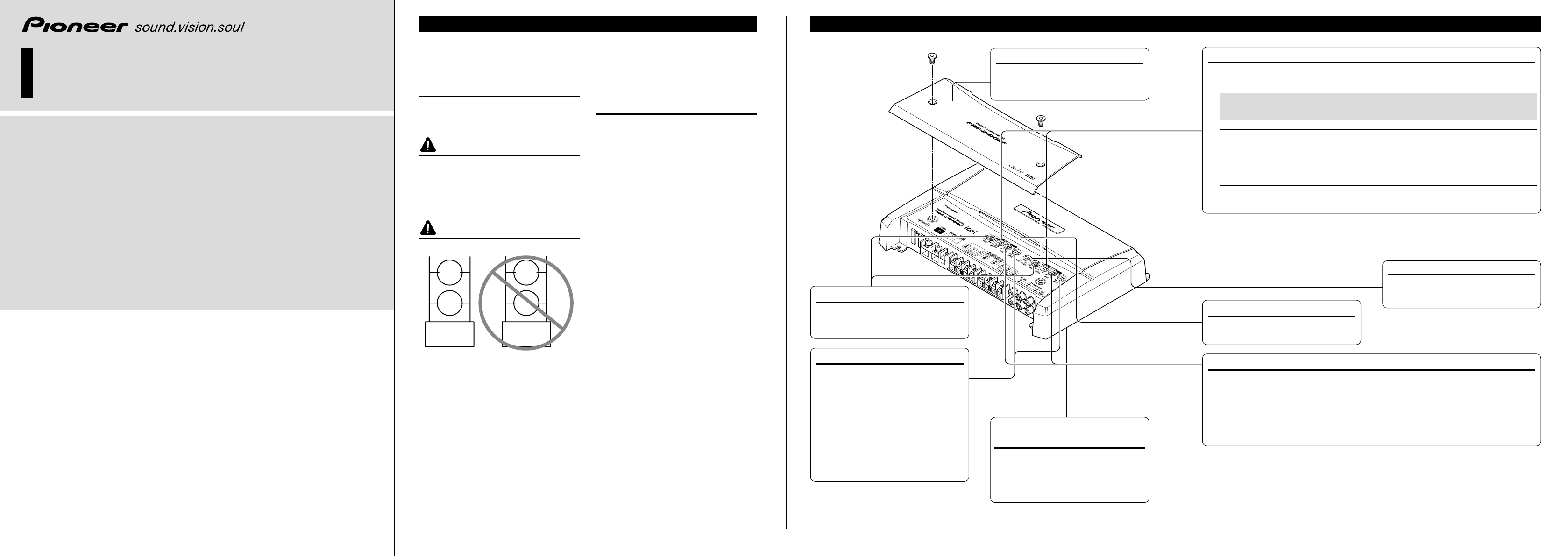
Gain Control
Adjusting the gain controls A and B will help match the output of the car stereo to the Pioneer
amplifier. Normally, set the gain controls to the NORMAL position. If the output is low, even
when the volume of the car stereo is turned up, turn these controls clockwise. If there is distortion when the volume of the car stereo is turned up, turn these controls counter-clockwise.
• If you only use one input plug, set the gain controls for speaker outputs A and B to the same position.
• When using with an RCA equipped car stereo (standard output of 500 mV), set to the NORMAL
position. When using with an RCA equipped Pioneer car stereo with max. output of 4 V or more,
adjust level to match the car stereo output level.
Power Indicator
The power indicator lights when the
power is switched on.
Input Select Switch
For two-channel input, slide this switch
to the left. For four-channel input, slide
this switch to the right.
Cut Off Frequency Control
If the LPF/HPF select switch is set to
LPF or HPF, you can select a cut off
frequency from 40 Hz to 500 Hz.
BFC (Beat Frequency Control)
Switch
BFC switch is on the bottom of the unit.
If you hear a beat while listening to an
AM broadcast with your car stereo,
change the BFC switch using a small
standard tip screwdriver.
Terminal Cover
Before setting up the unit, unfasten the
screws with a 4 mm hexagonal wrench
and remove the terminal cover.
LPF (Low-Pass Filter)/HPF (High-Pass Filter) Select Switch
Set the LPF/HPF select switch as follows according to the type of speaker that is connected
to the speaker output connector and the car stereo system:
LPF/HPF Select Audio frequency range Speaker Remarks
Switch to be output Type
LPF (Left) * — 40 Hz to 500 Hz Subwoofer Connect a subwoofer.
OFF (Center) Full range Full range
HPF (Right) * 40 Hz to 500 Hz — Full range Use if you want to cut the
very low frequency range*
because it is not necessary
for the speakers you are
using.
* See the “Cut Off Frequency Control” section.
Input Switch
It is possible to input from a car stereo
external output (subwoofer output) or a
car stereo speaker output. When using
an external output (subwoofer output),
slide the switch to the left. For connection instructions, see the “Connection
Diagram” section. When using a speaker output, slide the switch to the right.
In this case, it is necessary to use the
supplied speaker input wire with RCA
pin cord. For details, see the “Using the
Speaker Input” section.
• To adjust the switch, use standard tip screwdriver if needed.
Diagram A - Proper
8
+
-
Ohm
Speaker
8
+
-
Ohm
Speaker
L+ R-
Pioneer
Amplifier
4 Ohm Bridged Mode
Diagram B - Improper
4
+
-
Ohm
Speaker
4
+
-
Ohm
Speaker
L+ R-
Pioneer
Amplifier
2 Ohm Bridged Mode

Connecting the Power Terminal
• Always use the special red battery and ground
wire [RD-223], which is sold separately. Connect
the battery wire directly to the car battery positive
terminal (+) and the ground wire to the car body.
1. Pass the battery wire from the
engine compartment to the interior
of the vehicle.
• After making all other connections to the
amplifier, connect the battery wire terminal of
the amplifier to the positive (+) terminal of
the battery.
2. Twist the battery wire, ground wire
and system remote control wire.
3. Attach lugs to wire ends. Lugs not
supplied.
• Use pliers, etc., to crimp lugs to wires.
4. Connect the wires to the terminal.
• Fix the wires securely with the terminal
screws.
WARNING
Failure to securely fasten the battery wire to the terminal using the terminal screws could cause the terminal area to overheat and could result in damage
and injury including minor burns.
Fuse (30 A)
Engine
compartment
Interior of
the vehicle
Drill a 14 mm
hole into the
vehicle body.
Insert the O-ring rubber
grommet into the vehicle
body.
Twi st
Positive terminal
GND terminal
Power terminal
Battery wire
System remote
control terminal
System remote
control wire
Ground wire
Fuse (30 A)
Battery wire
Ground wire
Lug
Lug
Connecting the Unit <ENGLISH>
CAUTION
• Disconnect the negative (–) terminal of the battery
to avoid the risk of short-circuit and damage to
the unit.
• Secure the wiring with cable clamps or adhesive
tape. To protect the wiring, wrap adhesive tape
around it where they lie against metal parts.
• Do not route wires where they will get hot, for
example where the heater will blow over them. If
the insulation heats up, it may become damaged,
resulting in a short-circuit through the vehicle
body.
• Make sure that wires will not interfere with moving parts of the vehicle, such as the gearshift,
handbrake or seat sliding mechanism.
• Do not shorten any wires. Otherwise the protection circuit may fail to work when it should.
• Never feed power to other equipment by cutting
the insulation of the power supply wire to tap
from the wire. The current capacity of the wire
will be exceeded, causing overheating.
• Never replace the fuse with one of greater value
or rating than the original fuse. Use of an improper fuse could result in overheating and smoke and
could cause damage to the product and injury
including burns.
Speaker Channel Speaker Type Power
Four-channel
Subwoofer Nominal input: Min. 70 W
Other than subwoofer Max. input: Min. 150 W
Two-channel
Subwoofer Nominal input: Min. 200 W
Other than subwoofer Max. input: Min. 600 W
Three-channel Subwoofer Nominal input: Min. 70 W
Speaker output A Other than subwoofer Max. input: Min. 150 W
Three-channel Subwoofer Nominal input: Min. 200 W
Speaker output B Other than subwoofer Max. input: Min. 600 W
CAUTION:
To prevent damage and/or injury
• Do not ground the speaker wire directly or connect a negative (–) lead wire for several speakers.
• This unit is for vehicles with a 12-volt battery and
negative grounding. Before installing it in a recreational vehicle, truck or bus, check the battery
voltage.
• If the car stereo is kept on for a long time while
the engine is at rest or idling, the battery may go
dead. Turn the car stereo off when the engine is at
rest or idling.
• If the system remote control wire of the amplifier
is connected to the power terminal through the
ignition switch (12 V DC), the amplifier will
always be on when the ignition is on— regardless
of whether the car stereo is on or off. Because of
this, the battery could go dead if the engine is at
rest or idling.
• Speakers to be connected to the amplifier should
conform with the standards listed below. If they
do not conform, they may catch fire, emit smoke
or become damaged. The speaker impedance must
be 2 to 8 ohms. But in case of two-channel and
other bridge connections, the speaker impedance
must be 4 to 8 ohms.
• Install and route the separately sold battery wire
as far away as possible from the speaker wires.
Install and route the separately sold battery wire,
ground wire, speaker wires and the amplifier as
far away as possible from the antenna, antenna
cable and tuner.
• Cords for this product and those for other products may be different colors even if they have the
same function. When connecting this product to
another product, refer to the supplied manuals of
both products and connect cords that have the
same function.
Connection Diagram
• This diagram shows connections using external output (subwoofer output). Slide the input switch to the left.
• When you connect with speaker output, connections defers from the diagram. For details, see the “Using the
Speaker Input” section. In either case, you need to set the input switch. For details, see the “Setting the Unit”
section.
Connecting the Speaker Output
Terminals
1. Expose the end of the speaker wires
using nippers or a cutter by about
10 mm and twist.
2. Attach lugs to speaker wire ends.
Lugs not supplied.
• Use pliers, etc., to crimp lugs to wires.
3. Connect the speaker wires to the
speaker output terminals.
• Fix the speaker wires securely with the termi-
nal screws.
Using the Speaker Input
Connect the car stereo speaker output
wires to the amplifier using the supplied
speaker input wire with RCA pin cord.
• Slide the input switch to the right.
• For four-channel input, connect two speaker
input wires with RCA pin cord to RCA input
jack A and B. Be sure to slide the input select
switch to the right.
• For two-channel input, connect the speaker
input wire with RCA pin cord to RCA input
jack A. Do not connect anything to RCA
input jack B. Be sure to slide the input select
switch to the left.
7 Connections when using the speaker
input
• As a result of connecting the car stereo speaker
output wire to the amplifier, the power of the
amplifier is turned on automatically when the car
stereo is turned on. It is not necessary to connect
the system remote control wire in this case.
Note:
• Connect the system remote control wire when the
power of the amplifier is not to be turned on when
the car stereo is turned on.
10 mm
Twi st
Speaker
output
terminal
Terminal screw
Speaker wire
Lug
Speaker wire
Grommet
RCA input
Special red battery wire [RD-223] (sold separately)
After making all other connections at the amplifier,
connect the battery wire terminal of the amplifier to
the positive (+) terminal of the battery.
Ground wire (Black) [RD-223] (sold separately)
Connect to metal body or chassis.
Amplifier with
RCA input jacks
Car stereo with
RCA output jacks
System remote control wire (sold separately)
Connect the male terminal of this wire to the system remote control terminal of the car stereo
(SYSTEM REMOTE CONTROL). The female terminal can be connected to the auto-antenna relay
control terminal. If the car stereo does not have a system remote control terminal, connect the male
terminal to the power terminal through the ignition switch.
Fuse (30 A)
Fuse (30 A)
Connecting wire with
RCA pin plugs (sold
separately).
Speaker output terminal
See the “Connecting the
Speakers and Input
Wires” section for
speaker connection
instructions.
Fuse (30 A) × 2
External Output
If only one input plug is used, do
not connect anything to RCA
input jack B.
RCA input jack B
RCA output jack
RCA input jack A
Speaker output
Speaker input
wire with RCA
pin cord
To RCA input
jack of this unit.
Car stereo
White: Black: Black: Red:
Left + Left ≠ Right ≠ Right +
 Loading...