

Pioneer PRSD-410, PRSD-4100-F Service manual

This file was downloaded and provided FREE OF CHARGE
from the ManualDirectory community.
You can find many free to download Service Manuals & Schematics at
http://www.manualdirectory.co.uk
ORDER NO.
CRT3857
PRS-D4100F/XU/UC
BRIDGEABLE FOUR-CHANNEL POWER AMPLIFIER
PRS-D4100F
PRS-D410
PRS-D4100F
/XU/EW5
/XU/ES
/XU/UC
For details, refer to "Important Check Points for Good Servicing".
PIONEER CORPORATION 4-1, Meguro 1-chome, Meguro-ku, Tokyo 153-8654, Japan
PIONEER ELECTRONICS (USA) INC. P.O. Box 1760, Long Beach, CA 90801-1760, U.S.A.
PIONEER EUROPE NV Haven 1087, Keetberglaan 1, 9120 Melsele, Belgium
PIONEER ELECTRONICS ASIACENTRE PTE. LTD. 253 Alexandra Road, #04-01, Singapore 159936
PIONEER CORPORATION 2006
K-ZZA. DEC. 2006 Printed in Japan

1234
SAFETY INFORMATION
CAUTION
A
This service manual is intended for qualified service technicians; it is not meant for the casual do-it-yourselfer.
Qualified technicians have the necessary test equipment and tools, and have been trained to properly and safely repair
complex products such as those covered by this manual.
Improperly performed repairs can adversely affect the safety and reliability of the product and may void the warranty. If you
are not qualified to perform the repair of this product properly and safely, you should not risk trying to do so and refer the
repair to a qualified service technician.
WARNING
This product contains lead in solder and certain electrical parts contain chemicals which are known to the state of California
B
to cause cancer, birth defects or other reproductive harm.
Health & Safety Code Section 25249.6 - Proposition 65
- Service Precaution
1 You should conform to the regulations governing the product (safety, radio and noise, and other regulations),
and should keep the safety during servicing by following the safety instructions described in this manual.
2 Be careful in handling ICs. Some ICs such as MOS type are so fragile that they can be damaged by
electrostatic induction.
C
D
E
F
2
1234
PRS-D4100F/XU/UC
5678
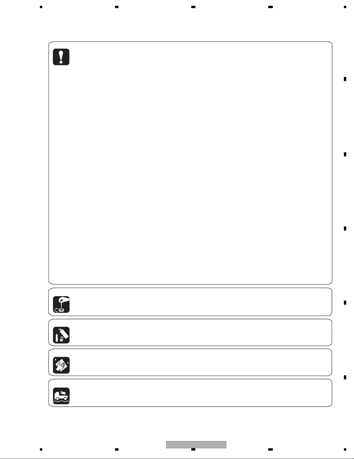
[Important Check Points for Good Servicing]
In this manual, procedures that must be performed during repairs are marked with the below symbol.
Please be sure to confirm and follow these procedures.
1. Product safety
Please conform to product regulations (such as safety and radiation regulations), and maintain a safe servicing environment by
following the safety instructions described in this manual.
1 Use specified parts for repair.
Use genuine parts. Be sure to use important parts for safety.
2 Do not perform modifications without proper instructions.
Please follow the specified safety methods when modification(addition/change of parts) is required due to interferences such as
radio/TV interference and foreign noise.
3 Make sure the soldering of repaired locations is properly performed.
When you solder while repairing, please be sure that there are no cold solder and other debris.
Soldering should be finished with the proper quantity. (Refer to the example)
4 Make sure the screws are tightly fastened.
Please be sure that all screws are fastened, and that there are no loose screws.
5 Make sure each connectors are correctly inserted.
Please be sure that all connectors are inserted, and that there are no imperfect insertion.
6 Make sure the wiring cables are set to their original state.
Please replace the wiring and cables to the original state after repairs.
In addition, be sure that there are no pinched wires, etc.
7 Make sure screws and soldering scraps do not remain inside the product.
Please check that neither solder debris nor screws remain inside the product.
8 There should be no semi-broken wires, scratches, melting, etc. on the coating of the power cord.
Damaged power cords may lead to fire accidents, so please be sure that there are no damages.
If you find a damaged power cord, please exchange it with a suitable one.
9 There should be no spark traces or similar marks on the power plug.
When spark traces or similar marks are found on the power supply plug, please check the connection and advise on secure
connections and suitable usage. Please exchange the power cord if necessary.
0 Safe environment should be secured during servicing.
When you perform repairs, please pay attention to static electricity, furniture, household articles, etc. in order to prevent injuries.
Please pay attention to your surroundings and repair safely.
A
B
C
D
2. Adjustments
To keep the original performance of the products, optimum adjustments and confirmation of characteristics within specification.
Adjustments should be performed in accordance with the procedures/instructions described in this manual.
3. Lubricants, Glues, and Replacement parts
Use grease and adhesives that are equal to the specified substance.
Make sure the proper amount is applied.
4. Cleaning
For parts that require cleaning, such as optical pickups, tape deck heads, lenses and mirrors used in projection monitors, proper
cleaning should be performed to restore their performances.
5. Shipping mode and Shipping screws
To protect products from damages or failures during transit, the shipping mode should be set or the shipping screws should be
installed before shipment. Please be sure to follow this method especially if it is specified in this manual.
56
PRS-D4100F/XU/UC
E
F
7
8
3

1234
CONTENTS
SAFETY INFORMATION ..................................................................................................................................... 2
1. SPECIFICATIONS ............................................................................................................................................ 5
2. EXPLODED VIEWS AND PARTS LIST ............................................................................................................ 6
A
B
2.1 PACKING ................................................................................................................................................... 6
2.2 EXTERIOR................................................................................................................................................. 8
3. BLOCK DIAGRAM AND SCHEMATIC DIAGRAM ..........................................................................................10
3.1 SCHEMATIC DIAGRAM(GUIDE PAGE) .................................................................................................. 10
4. PCB CONNECTION DIAGRAM ..................................................................................................................... 16
4.1 AMP PCB................................................................................................................................................. 16
4.2 CONTROL PCB ....................................................................................................................................... 20
5. ELECTRICAL PARTS LIST ............................................................................................................................ 21
6. ADJUSTMENT ............................................................................................................................................... 28
7. GENERAL INFORMATION............................................................................................................................. 29
7.1 DIAGNOSIS ............................................................................................................................................. 29
7.1.1 DISASSEMBLY ..................................................................................................................................... 29
7.1.2 CONNECTOR FUNCTION DESCRIPTION.......................................................................................... 30
7.2 IC ............................................................................................................................................................. 31
8. OPERATIONS ................................................................................................................................................ 34
C
D
E
F
4
1234
PRS-D4100F/XU/UC

5678
1. SPECIFICATIONS
A
B
C
D
E
56
PRS-D4100F/XU/UC
F
7
8
5
N
1234
2. EXPLODED VIEWS AND PARTS LIST
OTES : • Parts marked by " * " are generally unavailable because they are not in our Master Spare Parts List.
• The > mark found on some component parts indicates the importance of the safety factor of the part.
A
Therefore, when replacing, be sure to use parts of identical designation.
• Screw adjacent to mark on the product are used for disassembly.
• For the applying amount of lubricants or glue, follow the instructions in this manual.
(In the case of no amount instructions,apply as you think it appropriate.)
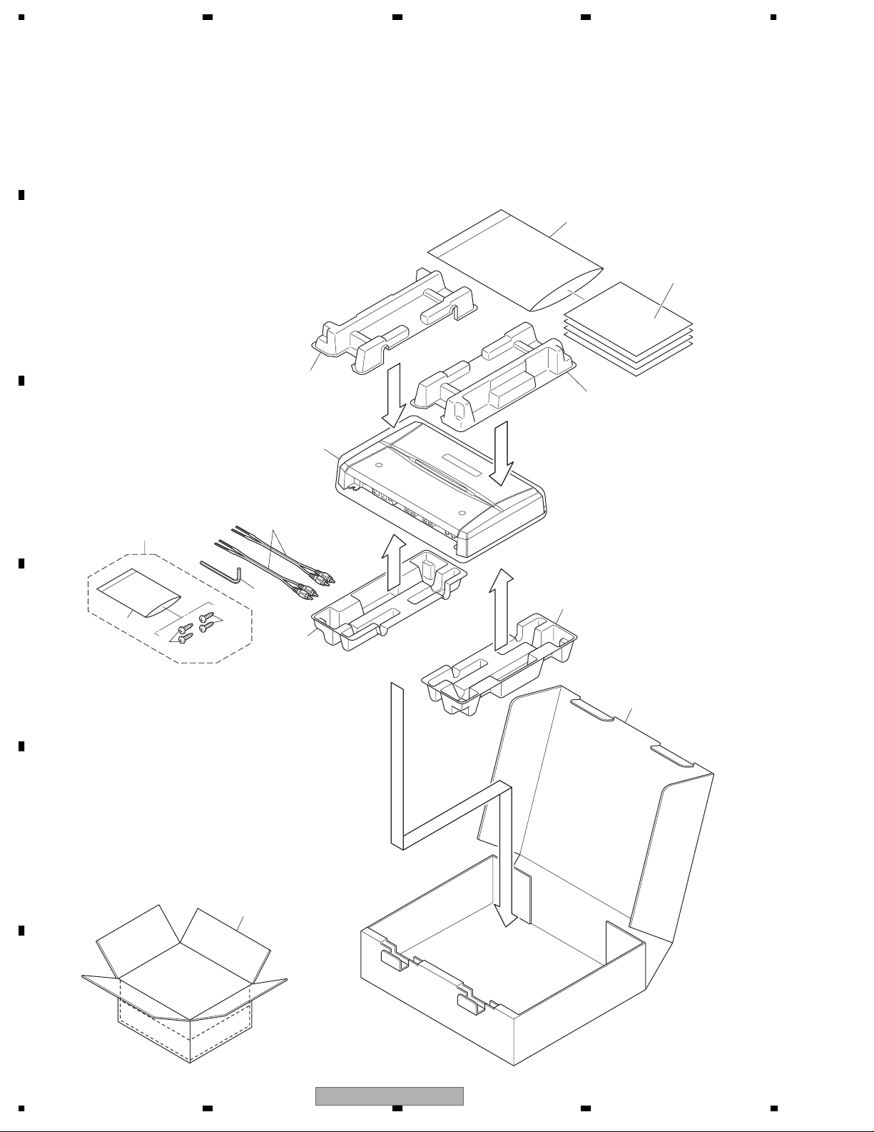
2.1 PACKING
"
4
B
12
13
7
C
14
6
11
10
1
3
2
D
2
5
8
E
9
F
6
1234
PRS-D4100F/XU/UC
5678
(1) PACKING SECTION PARTS LIST
Mark No. Description Part No.
1 Screw Assy CEA5330
2 Screw BYC40P180FTB
* 3 Polyethylene Sheet CNM4338
4 Polyethylene Bag CEG1116
5-1 Owner's Manual See Contrast table(2)
5-2 Owner's Manual See Contrast table(2)
* 5-3 Warranty Card See Contrast table(2)
5-4 Caution Card YRP5001
6 Cord Assy YDE5010
Mark No. Description Part No.
7 Polyethylene Bag See Contrast table(2)
8 Carton See Contrast table(2)
9 Contain Box See Contrast table(2)
10 Protector YHP5006
11 Protector YHP5007
12 Protector YHP5012
13 Protector YHP5013
14 Shaft YLP5001
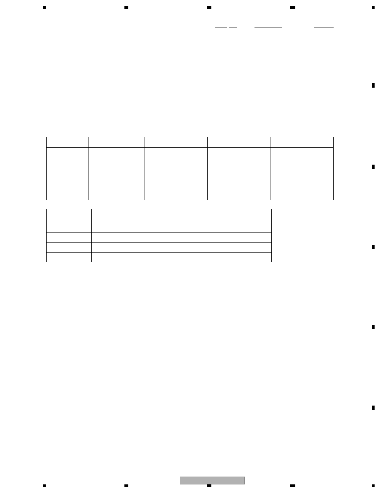
(2) CONTRAST TABLE
PRS-D4100F/XU/UC, PRS-D410/XU/EW5 and PRS-D4100F/XU/ES are constructed the same except for the following:
Mark No. Description PRS-D4100F/XU/UC PRS-D410/XU/EW5 PRS-D4100F/XU/ES
5-1 Owner's Manual YRD5130 YRD5127 YRD5128
5-2 Owner's Manual Not used Not used YRD5129
* 5-3 Warranty Card CRY1070 CRY1157 Not used
7 Polyethylene Bag YEG5004 YEG5003 YEG5003
8 Car ton YHG5157 YHG5155 YHG5156
A
B
9 Contain Box YHL5157 YHL5155 YHL5156
Owner's Manual
Part No. Language
YRD5130 English, French, Spanish
YRD5127 English, Spanish, German, French, Italian, Dutch, Russian
YRD5128 English, Spanish
YRD5129 Portuguese(B), Arabic
C
D
E
56
PRS-D4100F/XU/UC
F
7
8
7
1234
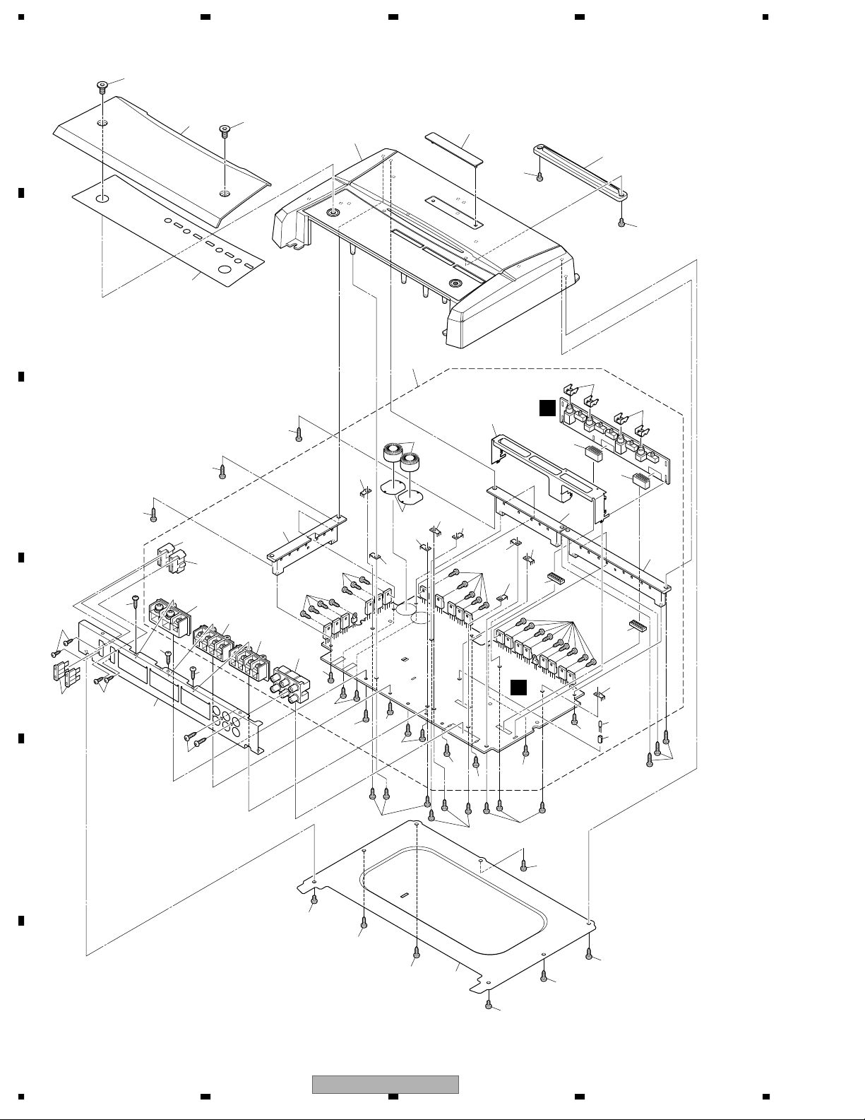
2.2 EXTERIOR
A
6
10
6
9
41
40
2
2
B
C
1
5
4
D
43
4
42
11
14
14
32
37
34
17
46
45
1
23
B
31
38
16
33
13
1
1
29
30
26
27
5
5
39
13
28
25
12
21
13
20
36
44
19
18
35
22
24
13
A
7
5
12
15
15
15
15
12
12
12
E
2
F
8
1234
PRS-D4100F/XU/UC
3
3
3
8
3
3
3
3
3
2

>
5678
(1) EXTERIOR SECTION PARTS LIST
Mark No. Description Part No.
1 Screw BBZ30P100FTB
2 Screw BSZ30P050FTC
3 Screw(M3 x 8) CBA2011
4 Screw PPZ20P060FTB
5 Screw PPZ30P100FTB
6 Screw(M6 x 10) YBA5002
7 Panel YNB5005
8 Case YNB5022
9 Heat Sink YNR5056
10 Cover See Contrast table(2)
11 Amp Unit YWH5015
12 Screw BBZ30P080FSN
13 Screw(M3 x 8) CBA2011
14 Holder CND2466
15 Screw PPZ30P100FSN
16 Terminal(CN501) VNF1084
17 Terminal(CN503) VNF1084
18 Terminal(CN505) VNF1084
19 Terminal(CN506) VNF1084
20 Terminal(CN606) VNF1084
21 Terminal(CN607) VNF1084
22 Terminal(CN608) VNF1084
23 Terminal(CN821) VNF1084
24 Terminal(CN822) VNF1084
25 Pin Jack(CN851) YKB5005
Mark No. Description Part No.
26 Terminal(CN601) YKE5002
27 Terminal(CN301) YKE5003
28 Terminal(CN302) YKE5003
29 Fuse Holder(CN602) YKR5001
30 Fuse Holder(CN603) YKR5001
31 Connector(CN860) YKS5008
32 Connector(CN861) YKS5008
33 Connector(CN858) YKS5009
34 Connector(CN859) YKS5009
35 Holder YND5008
36 Insulator YNM5045
37 Sub Heat Sink YNR5066
38 Sub Heat Sink YNR5067
39 Sub Heat Sink YNR5068
40 Lighting Conductor Unit YXA5256
* 41 Badge See Contrast table(2)
* 42 Plate See Contrast table(2)
43 Fuse(30 A)(FU101, FU102) CEK1330
44 Choke Coil(L602, L603) CTH1326
45 Spacer YNS5118
46 LED(D604) NSPB346BS-5859
A
B
C
(2) CONTRAST TABLE
PRS-D4100F/XU/UC, PRS-D410/XU/EW5 and PRS-D4100F/XU/ES are constructed the same except for the following:
Mark No. Description PRS-D4100F/XU/UC PRS-D410/XU/EW5 PRS-D4100F/XU/ES
10 Cover YNR5076 YNR5074 YNR5075
* 41 Badge YAH5009 YAH5007 YAH5007
* 42 Plate YAH5013 YAH5012 YAH5013
D
E
56
PRS-D4100F/XU/UC
F
7
8
9
A-a
A-b
A-a
A-b
A-b
A-a
F
205dB(SPIN)
1234
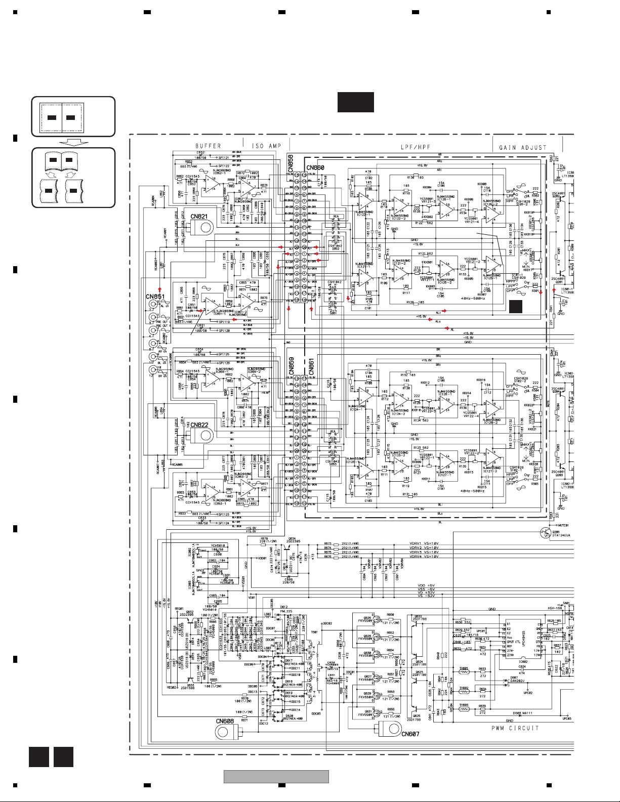
3. BLOCK DIAGRAM AND SCHEMATIC DIAGRAM
3.1 SCHEMATIC DIAGRAM(GUIDE PAGE)
A
Note: When ordering service parts, be sure to refer to " EXPLODED VIEWS AND PARTS LIST" or
"ELECTRICAL PARTS LIST".
INPUT
INPUT
SELECT
A-a
CUT
OFF
FREQUENCY
CONTROL
18.32 dBs(RCA IN)
6.2 dBs(SP IN)
Large size
A-b
A-b
A-b
SCH diagram
Guide page
Detailed page
A-a
A-a
A-a
B
18.5 dBs(MAX)
(RCA IN)
18.5 dBs(MAX)
(SP IN)
C
18.32 dBs(RCA IN)
6.2 dBs(SP IN)
LPF/HPF
GAIN
CONTROL
B
CONTROL PCB
10K(A)
-8.38 dBs(RCA IN)
GAIN
CONTROL
10K(A)
B
LPF/HPF
INPUT
D
CUT
OFF
FREQUENCY
CONTROL
E
320µH
320µH
F
A B
10
1234
PRS-D4100F/XU/UC
 Loading...