

Page 1

ENGLISH
ESPAÑOL
DEUTSCH
FRANÇAIS
ITALIANO
NEDERLANDS
кмллдав
CLASS D MONO AMPLIFIER
AMPLIFICATEUR MONO DE CLASSE D
Owner’s Manual
PRS-D1000M
Mode d’emploi
Page 2

1
Before Using This Product ...................... 1
Product registration ............................................ 1
In case of trouble .............................................. 2
About This Product ............................................ 2
CAUTION ........................................................ 2
WARNING ........................................................2
Setting the Unit .......................................... 3
Terminal Cover ................................................ 3
Power Indicator ................................................ 3
Subsonic Select Switch .................................... 3
Bass Boost Control ............................................ 3
BFC (Beat Frequency Control) Switch ............ 3
MODE SELECT Switch .................................. 4
Gain Control ...................................................... 4
Cut Off Frequency Control for LPF .................. 4
Input Switch ...................................................... 4
POWER MODE Switch .................................... 4
Connecting the Unit .................................. 5
Connection Diagram ........................................ 6
Connecting the Power Terminal ........................ 7
Connecting the Speaker Output Terminals ...... 8
Using the Speaker Input .................................... 8
Connecting the Speaker Wires .......................... 9
Installation ................................................ 13
Example of installation on the floor mat
or on the chassis ...................................... 14
Replacing the terminal cover .......................... 14
Specifications .......................................... 15
Thank you for purchasing this PIONEER
product. Before attempting operation, be
sure to read this manual.
Private households in the 25 member
states of the EU, in Switzerland and
Norway may return their used electronic
products free of charge to designated collection facilities or to a retailer (if you purchase a similar new one).
For countries not mentioned above, please
contact your local authorities for the correct method of disposal.
By doing so you will ensure that your disposed product undergoes the necessary
treatment, recovery and recycling and thus
prevent potential negative effects on the
environment and human health.
Product registration
Visit us at the following site:
Register your product. We will keep the
details of your purchase on file to help you
refer to this information in the event of an
insurance claim such as loss or theft.
If you want to dispose this
product, do not mix it with
general household waste. There
is a separate collection system
for used electronic products in
accordance with legislation that
requires proper treatment,
recovery and recycling.
Contents Before Using This Product
Page 3

ENGLISH
ESPAÑOL
DEUTSCH
FRANÇAIS
ITALIANO
NEDERLANDS
кмллдав
2
In case of trouble
When the unit does not operate properly,
contact your dealer or the nearest authorized PIONEER Service Station.
About This Product
This product is a class D amplifier for the
subwoofer. If both L (left) and R (right)
channels are connected to the RCA input
of this product, output is mixed because
this product is a mono amplifier.
CAUTION
Never replace the fuse with one of greater
value or rating than the original fuse. Use
of an improper fuse could result in overheating and smoke and could cause damage to the product and injury including
burns.
WARNING
• Always use the special red battery and ground
wire [RD-223] and [RD-222], which are sold separately. Connect the battery wire directly to the
car battery positive terminal (+) and the ground
wire to the car body. There is the risk of a fuse
burning out if only one of these is connected.
• Do not touch the amplifier with wet hands.
Otherwise you may get an electric shock. Also,
do not touch the amplifier when it is wet.
• For traffic safety and to maintain safe driving
conditions, keep the volume low enough so that
you can still hear normal traffic sound.
• Check the connections of the power supply and
speakers if the fuse of the separately sold battery
wire or the amplifier fuse blows. Detect the cause
and solve the problem, then replace the fuse with
another one of the same size and rating.
• To prevent malfunction of the amplifier and
speakers, the protective circuit will cut the power
supply to the amplifier (sound will stop) when an
abnormal condition occurs. In such a case, switch
the power to the system OFF and check the
connection of the power supply and speakers.
Detect the cause and solve the problem.
• Contact the dealer if you cannot detect the cause.
• To prevent an electric shock or short-circuit
during connection and installation, be sure to
disconnect the negative (–) terminal of the battery
beforehand.
• Confirm that no parts are behind the panel when
drilling a hole for installation of the amplifier. Be
sure to protect all cables and important equipment
such as fuel lines, brake lines and the electrical
wiring from damage.
• DO NOT allow amplifier to come into contact
with liquids due to, for example, the location
where the amplifier is installed. Electrical shock
could result. Also, amplifier and speaker damage,
smoke, and overheating could result from contact
with liquids. In addition, the amplifier surface
and the surface of any attached speakers could
become hot to the touch and minor burns could
result.
Page 4
3
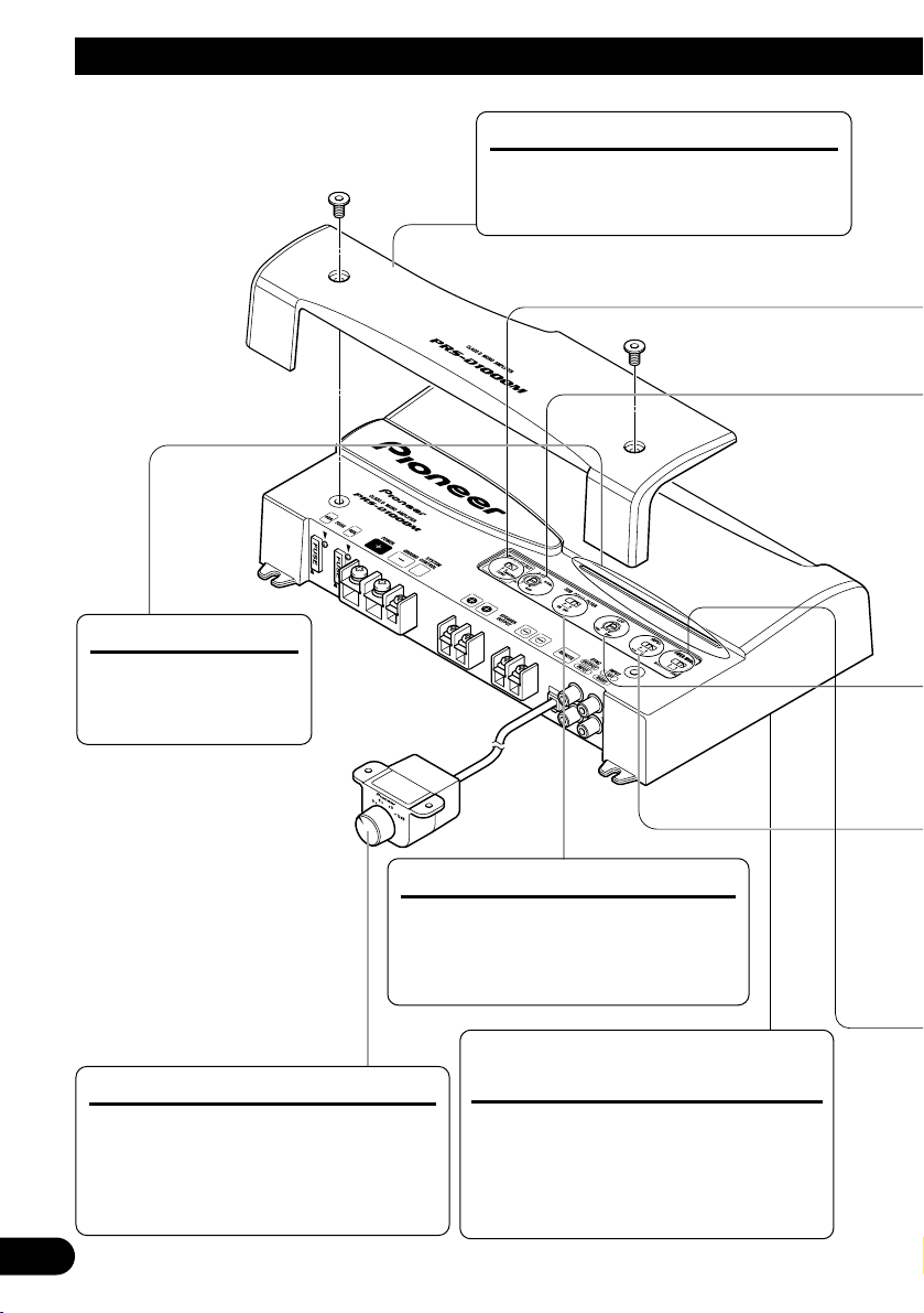
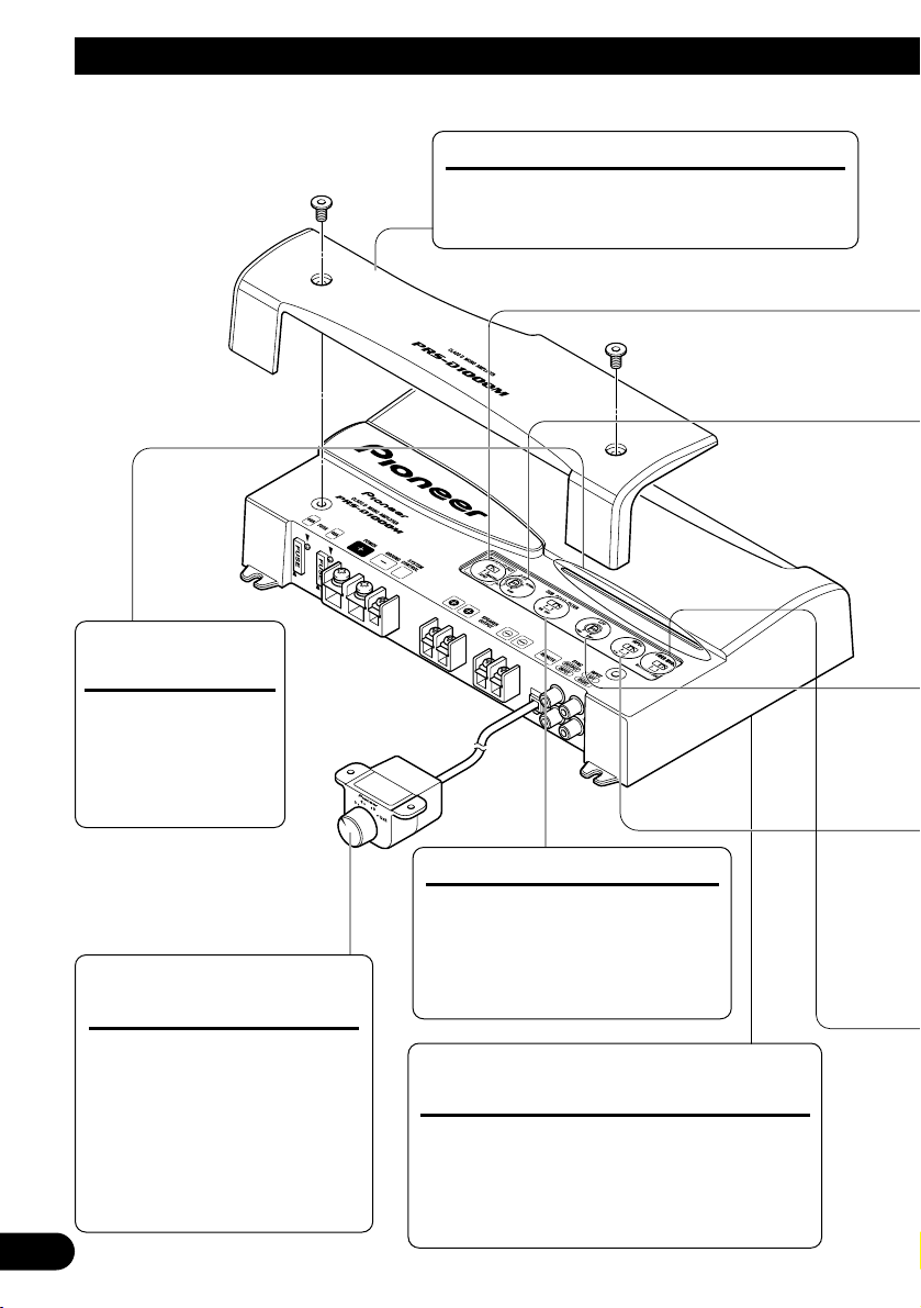
Setting the Unit
Power Indicator
The power indicator
lights when the power
is switched on.
Terminal Cover
Before setting up the unit, unfasten the
screws with a 4 mm hexagonal wrench
and remove the terminal cover.
Bass Boost Control
You can select a bass boost level from
0, 6, 9 and 12 dB.
For instruction of connecting the bass
boost remote control to the amplifier,
see the “Connection Diagram” section.
BFC (Beat Frequency Control)
Switch
BFC switch is on the bottom of the unit.
If you hear a beat while listening to an
MW/LW broadcast with your car
stereo, change the BFC switch using a
small standard tip screwdriver.
Subsonic Select Switch
The subsonic filter cuts inaudible
frequencies below 20 Hz to eliminate
unwanted vibrations and minimize
power loss.
Page 5
ENGLISH
ESPAÑOL
DEUTSCH
FRANÇAIS
ITALIANO
NEDERLANDS
кмллдав
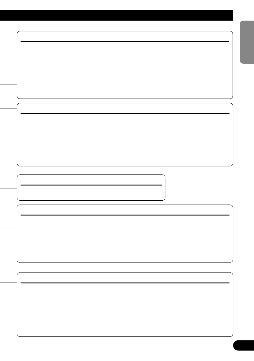
4
Gain Control
If the sound level is too low, even when the volume of the car stereo used along with this
power amplifier is turned up, turn gain control clockwise. If the sound distorts when the volume is turned up, turn the gain control counter-clockwise.
• When using with an RCA equipped car stereo (standard output of 500 mV), set to the NORMAL
position. When using with an RCA equipped Pioneer car stereo with max. output of 4 V or more,
adjust level to match the car stereo output level.
• If you hear too much noise when using the speaker input terminals, turn the gain control
counter-clockwise.
Input Switch
It is possible to input from a car stereo external output or a car stereo speaker output. Switch
the input switch before turning on the power. Since switching the input switch while the
power is on can cause a loud noise to be emitted from the speakers, the power is turned off
by a protection function. When using an external output, slide the switch to the left. For
connection instructions, see the “Connection Diagram” section. When using a speaker output, slide the switch to the right. In this case, it is necessary to use the supplied speaker input
wire with RCA pin cord. For details, see the “Using the Speaker Input” section.
MODE SELECT Switch
You can select amplifier’s sync mode from MASTER, SYNC and SYNC INV. Set the MODE
SELECT switch to the MASTER position when using one amplifier only. When using synchronously
connecting two or more of these amplifiers in combination, set the first amplifier to MASTER, and set
the remaining amplifiers to SYNC or SYNC INV according to the manner in which they are connected. The only time the amplifier is switched to the SYNC INV mode is when amplifiers are synchronously connected with the ex. bridge.
When switching to the SYNC INV mode, the seal over the MODE SELECT switch must be peeled off
and you can find SYNC INV switch. Peel off the seal after checking that connections are correct. See
the “Connecting the Speaker Wires” section for details on the MODE SELECT switch.
POWER MODE Switch
When using speakers with synthetic impeadance 2 Ωto 8 Ω, slide the switch to the right
(NORMAL). When using speakers with synthetic impeadance from 1
Ω
to less than 2 Ω,
slide the switch to the left (HI-CURRENT). These settings are only used when using a single amplifier. See the “Connecting the Speaker Wires” section when combining the use of
multiple amplifiers.
If the speaker impedance exceeds 2
Ω
(4 Ωwhen using ex. bridge), although the POWER
MODE switch be may set to the HI-CURRENT position, setting to the NORMAL position
makes it possible to enjoy high power sound.
Cut Off Frequency Control for LPF
You can select a cut off frequency from 40 Hz to 240 Hz.
Page 6
5
Connecting the Unit
CAUTION:
To prevent damage and/or injury
• Do not ground the speaker wire directly or connect a negative (–) lead wire for several speakers.
• This unit is for vehicles with a 12-volt battery and
negative grounding. Before installing it in a recreational vehicle, truck or bus, check the battery
voltage.
• If the car stereo is kept on for a long time while
the engine is at rest or idling, the battery may go
dead. Turn the car stereo off when the engine is at
rest or idling.
• If the system remote control wire of the amplifier
is connected to the power terminal through the
ignition switch (12 V DC), the amplifier will
always be on when the ignition is on— regardless
of whether the car stereo is on or off. Because of
this, the battery could go dead if the engine is at
rest or idling.
• DO NOT connect a subwoofer with a lower
impedance than specified in the “Connecting the
Unit” section. Amplifier damage, smoke, and
overheating could result from a non-specified
connection. The amplifier surface could also
become hot to the touch and minor burns could
result.
• Connect either of three subwoofers to the amplifier; 1: a subwoofer with a 420 W or larger nominal input and an impedance 4 Ω, 2: a subwoofer
with a 600 W or larger nominal input and an
impedance 2 Ω or 3: a subwoofer with a 600 W
or larger nominal input and an impedance 1 Ω. If
the nominal input and impedance are out of the
above ranges, the subwoofer may catch fire, emit
smoke or become damaged.
• Install and route the separately sold battery wire
as far away as possible from the speaker wires.
Install and route the separately sold battery wire,
ground wire, speaker wires and the amplifier as
far away as possible from the antenna, antenna
cable and tuner.
• Cords for this product and those for other products may be different colors even if they have the
same function. When connecting this product to
another product, refer to the supplied Installation
manuals of both products and connect cords that
have the same function.
CAUTION
• Disconnect the negative (–) terminal of the battery to avoid the risk of short-circuit and damage
to the unit.
• Secure the wiring with cable clamps or adhesive
tape. To protect the wiring, wrap adhesive tape
around it where they lie against metal parts.
• Do not route wires where they will get hot, for
example where the heater will blow over them. If
the insulation heats up, it may become damaged,
resulting in a short-circuit through the vehicle
body.
• Make sure that wires will not interfere with moving parts of the vehicle, such as the gearshift,
handbrake or seat sliding mechanism.
• Do not shorten any wires. Otherwise the protection circuit may fail to work when it should.
• Never feed power to other equipment by cutting
the insulation of the power supply wire to tap
from the wire. The current capacity of the wire
will be exceeded, causing overheating.
• Never replace the fuse with one of greater value
or rating than the original fuse. Use of an improper fuse could result in overheating and smoke and
could cause damage to the product and injury
including burns.
Page 7
ENGLISH
ESPAÑOL
DEUTSCH
FRANÇAIS
ITALIANO
NEDERLANDS
кмллдав
6
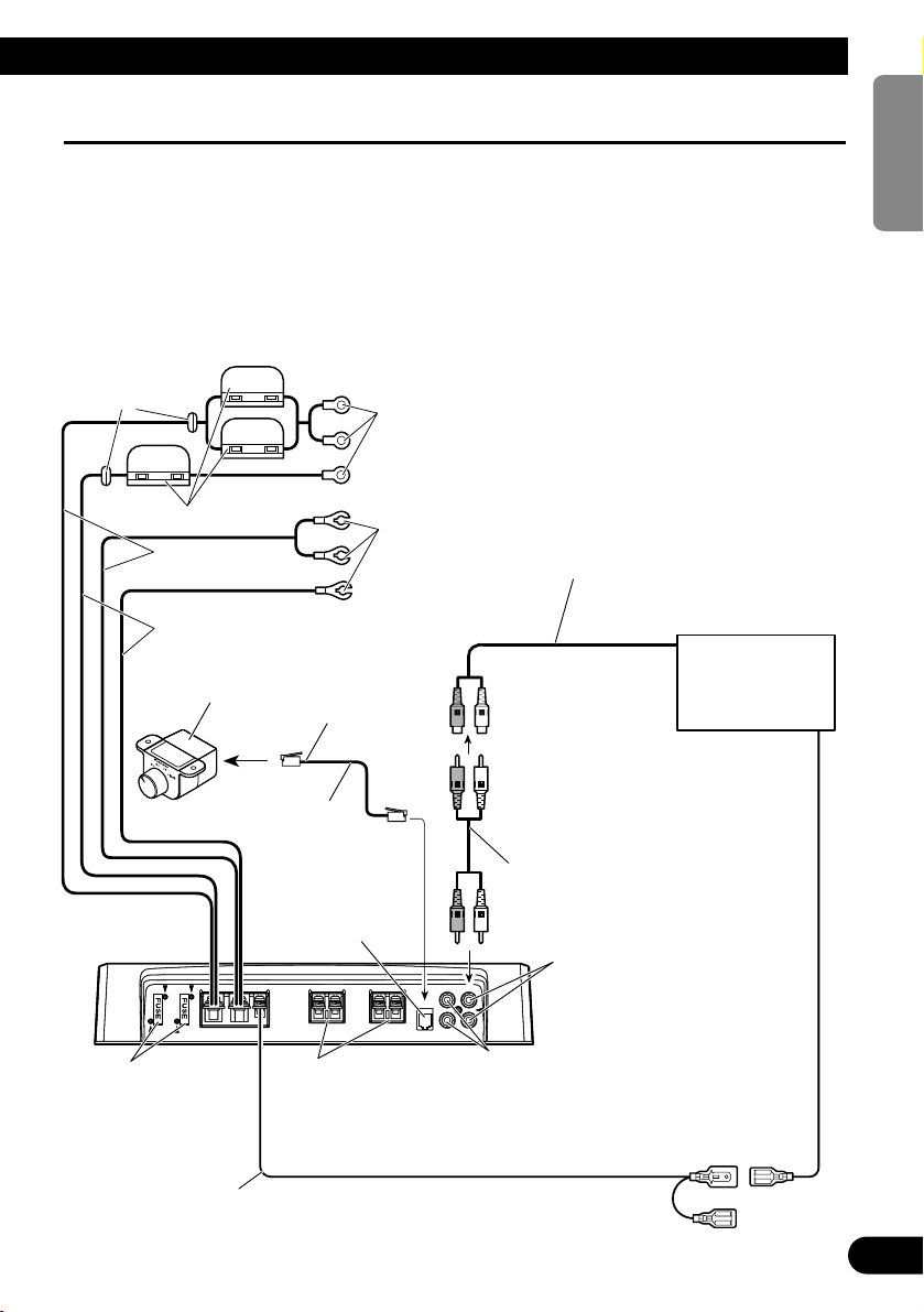
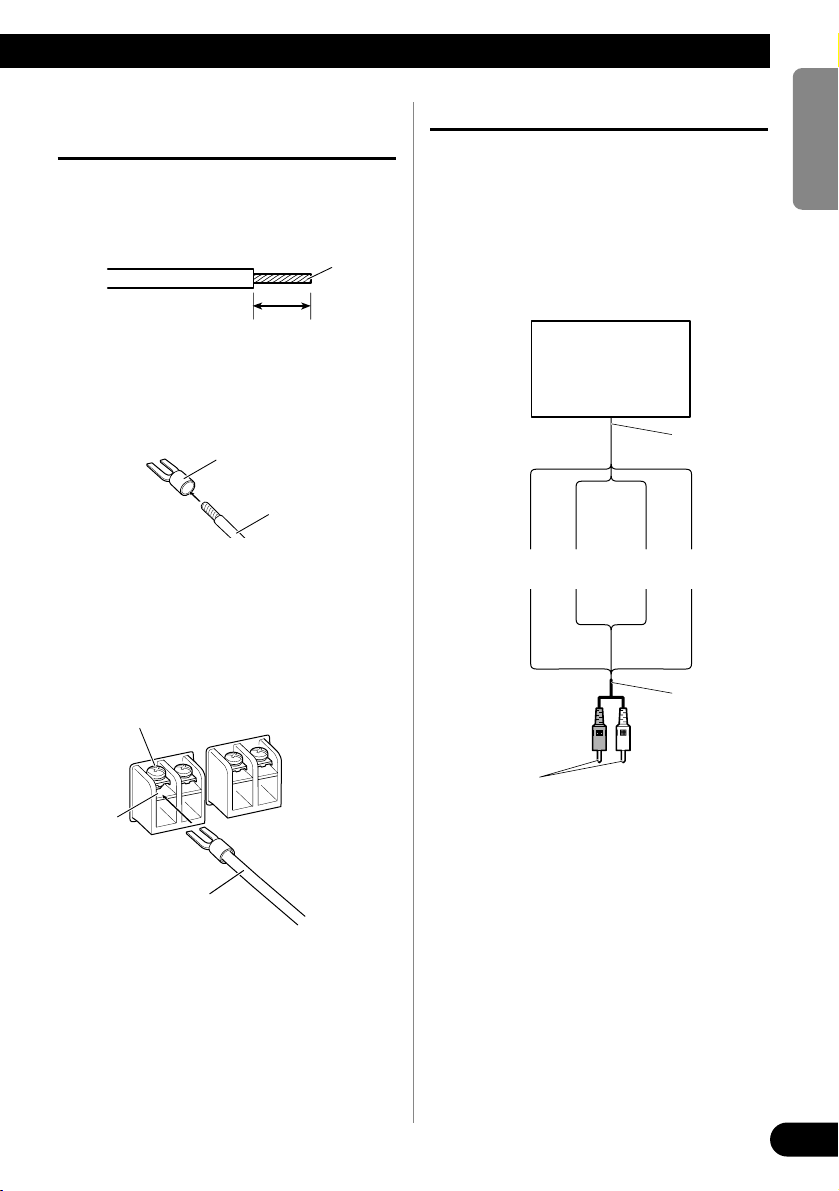
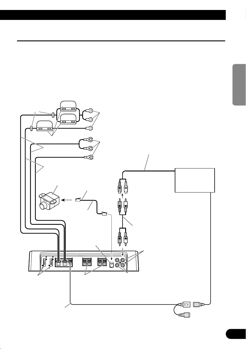
Connection Diagram
• This diagram shows connections using external output. Slide the input switch to the left.
• In the case of connecting the external output from a car stereo to an RCA input, use the jack used for fullrange output. This is because the LPF of the amplifier cannot be turned OFF. If this jack cannot be used,
connect the subwoofer output jack to the RCA input.
• When you connect with speaker output, connections defers from the diagram. For details, see the “Using
the Speaker Input” section. In either case, you need to set the input switch. For details, see the “Setting the
Unit” section.
• Always use the special red battery and ground wire ([RD-223] and [RD-222]), which are sold separately.
Connect the battery wire directly to the car battery positive terminal (+) and the ground wire to the car
body. There is the risk of a fuse burning out if only one of these is connected.
Fuse (40 A)
Car stereo with
RCA output jacks
External Output
Connecting wire with RCA
pin plugs (sold separately).
RCA input jack
System remote control wire (sold separately)
Connect the male terminal of this wire to the system remote control terminal of the car
stereo (SYSTEM REMOTE CONTROL). The female terminal can be connected to the
auto-antenna relay control terminal. If the car stereo does not have a system remote control
terminal, connect the male terminal to the power terminal through the ignition switch.
Speaker output terminal
See the “Connecting the
Speaker Wires” section for
speaker connection instructions.
Bass Boost Remote
Control Wire
Bass Boost
Remote Control
6 m
Jack for the bass boost
remote control
Connect this jack and
the bass boost remote
control with the bass
boost remote control
wire.
SYNC OUTPUT/SYNC INPUT jack
See the “Connecting the Speaker Wires”
section for SYNC OUTPUT/SYNC
INPUT jack connection instructions.
Fuse (30 A) × 3
Grommet
Special red battery wire
After making all other connections at the amplifier,
connect the battery wire terminal of the amplifier to
the positive (+) terminal of the battery.
Ground wire (black)
Connect to metal body or chassis.
[RD-223]
(sold separately)
[RD-222] (sold separately)
Page 8

7
Connecting the Unit
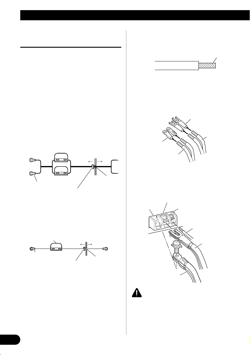
Connecting the Power Terminal
• Always use the special red battery and ground
wire ([RD-223] and [RD-222]), which are sold
separately. Connect the battery wire directly to
the car battery positive terminal (+) and the
ground wire to the car body. There is the risk of a
fuse burning out if only one of these is connected.
1. Pass the battery wire from the
engine compartment to the interior
of the vehicle.
• After making all other connections to the
amplifier, connect the battery wire terminal
of the amplifier to the positive (+) terminal of
the battery.
[RD-223]
[RD-222]
2. Twist the battery wire, ground wire
and system remote control wire.
3. Attach lugs to wire ends. Lugs not
supplied.
• Use pliers, etc., to crimp lugs to wires.
4. Connect the wires to the terminal.
• Fix the wires securely with the terminal
screws.
WARNING
Failure to securely fasten the battery wire to the terminal using the terminal screws could cause the terminal area to overheat and could result in damage
and injury including minor burns.
GND terminal
Power terminal
Battery wire
System remote
control terminal
System remote
control wire
Ground wire
Twist
Battery wire
Ground wire
Lug
Lug
Fuse (30 A)
Engine
compartment
Interior of
the vehicle
Drill a 14 mm
hole into the
vehicle body.
Insert the O-ring rubber
grommet into the vehicle
body.
Positive terminal
Fuse (30 A)
Fuse (30 A)
Engine
compartment
Interior of
the vehicle
Drill an 8 mm
hole into the
vehicle body.
Insert the O-ring rubber
grommet into the vehicle
body.
Positive terminal
Page 9
ENGLISH
ESPAÑOL
DEUTSCH
FRANÇAIS
ITALIANO
NEDERLANDS
кмллдав
8
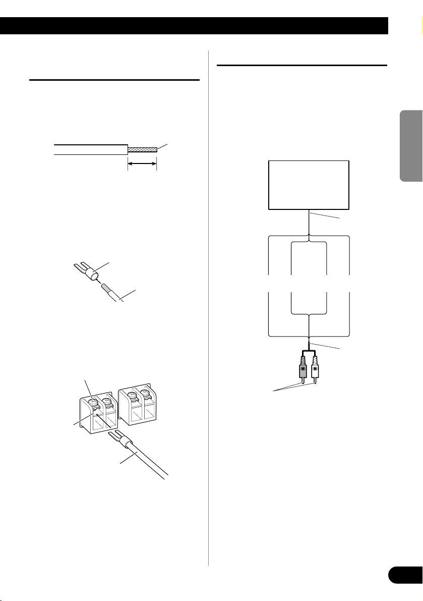
Connecting the Speaker Output
Terminals
1. Expose the end of the speaker wires
using nippers or a cutter by about
10 mm and twist.
2. Attach lugs to speaker wire ends.
Lugs not supplied.
• Use pliers, etc., to crimp lugs to wires.
3. Connect the speaker wires to the
speaker output terminals.
• Fix the speaker wires securely with the termi-
nal screws.
Using the Speaker Input
Connect the car stereo speaker output
wires to the amplifier using the supplied
speaker input wire with RCA pin cord.
• Slide the input switch to the right.
7 Connections when using the speaker
input
• As a result of connecting the car stereo speaker
output wire to the amplifier, the power of the
amplifier is turned on automatically when the car
stereo is turned on. It is not necessary to connect
the system remote control wire in this case.
• In the case the amplifier and head unit are connected using a speaker input wire with RCA pin
cord, the amplifier power is only turned on when
one amplifier is being used. If two or more amplifiers are synchronously connected in combination, connect the head unit and all of the amplifiers with the system remote control wire.
Note:
• Connect the system remote control wire when the
power of the amplifier is not to be turned on
when the car stereo is turned on.
10 mm
Twist
Speaker wire
Lug
Speaker
output
terminal
Terminal screw
Speaker wire
Speaker
output
Car Stereo
Speaker input
wire with RCA
pin cord
To RCA input
jack of this unit.
White: Black: Black: Red:
Left + Left ≠ Right ≠ Right +
Page 10
9
Connecting the Unit
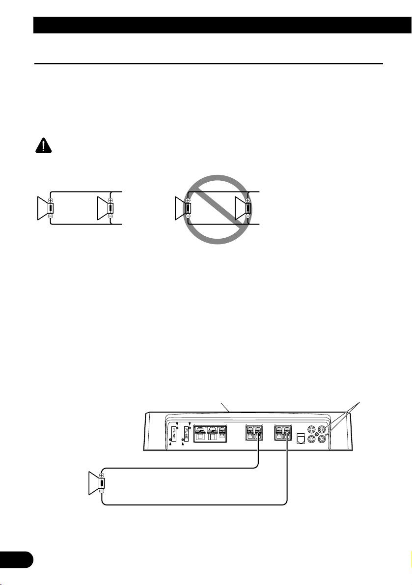
Connecting the Speaker Wires
Connect the speaker leads and set MODE SELECT switch and POWER MODE switch to suit the configuration according to the figures shown below and the next page.
• When synchronously connecting two or more amplifiers in combination, only use these amplifiers. Do not
mix these amplifiers with other amplifiers.
• When synchronously connecting two or more amplifiers in combination, set the gain control, subsonic
select switch, cut off frequency control for LPF and bass boost control on the amplifier that has been set to
MASTER with the MODE SELECT switch. These settings are inactive when set on an amplifier set to
SYNC or SYNC INV.
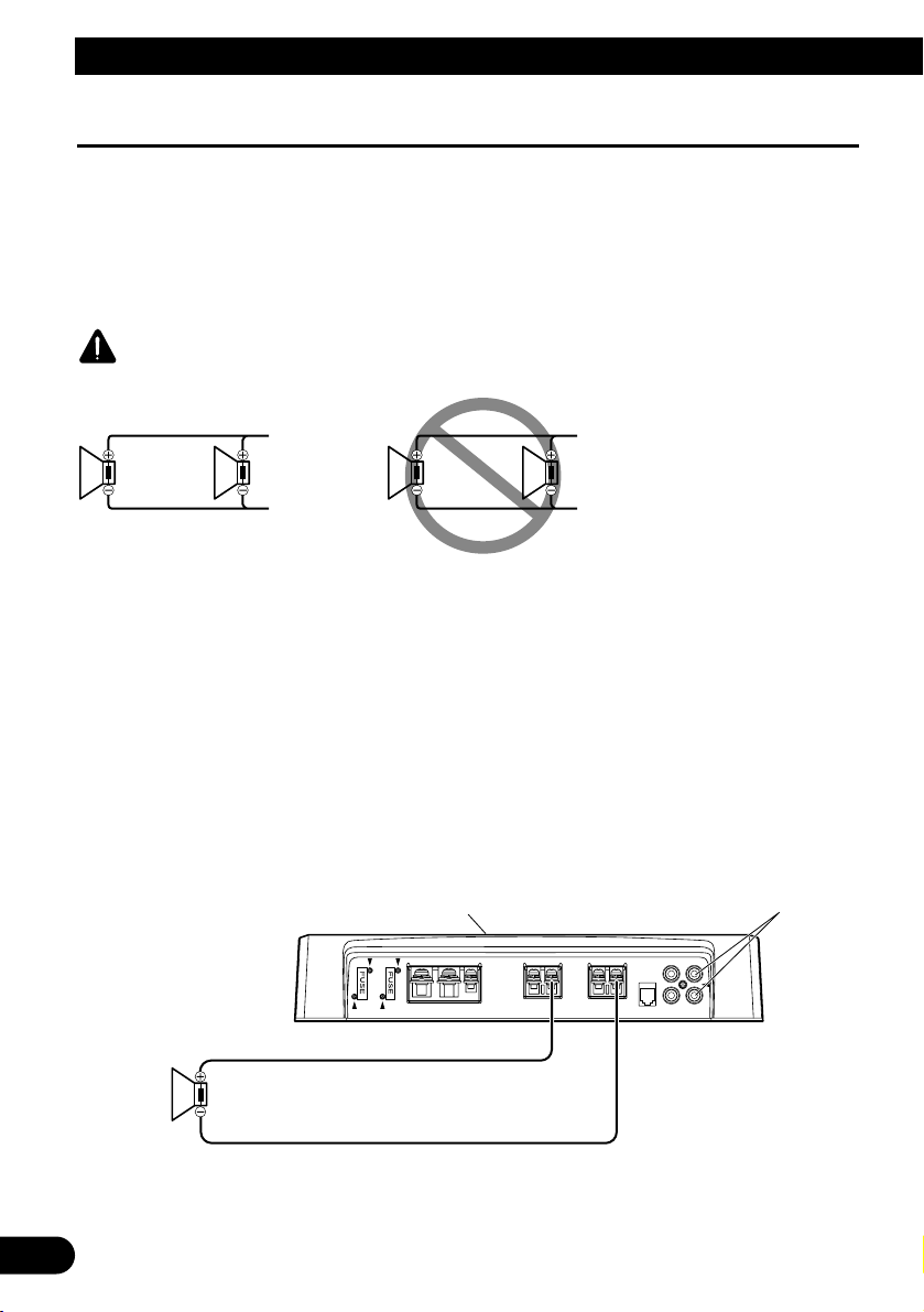
CAUTION
Do NOT install or use this amplifier by wiring speakers rated at 2 Ω (or lower) in parallel to achieve a 1 Ω (or
lower) bridged mode (Diagram B).
Amplifier damage, smoke, and overheating could result from improper bridging. The amplifier surface could
also become hot to the touch and minor burns could result.
To properly install or use a bridged mode and achieve a 2 Ω load, wire two 4 Ω speakers in parallel with Left
+ and Right – (Diagram A) or use a single 2 Ω speaker.
If the synthetic impedance is from 2 Ω to less than 4 Ω, always make sure to set the POWER MODE switch to
the HI-CURRENT position.
In addition, refer to the speaker instruction manual for information on the correct connection procedure.
Single Amplifier
• Use speakers having an impedance from 1 Ω to 8 Ω.
• The setting of the POWER MODE switch varies according to the speaker impedance. See the “Setting the
Unit” section for details.
r
MODE SELECT switch must
be in MASTER position.
Connect to a car stereo.
For details, see the “Connection Diagram”.
1 Ω to 8 Ω
Diagram A - Proper
Diagram B - Improper
4 Ω
Speaker
2 Ω Bridged Mode
4 Ω
Speaker
2 Ω
Speaker
1 Ω Bridged Mode
2 Ω
Speake
Page 11
ENGLISH
ESPAÑOL
DEUTSCH
FRANÇAIS
ITALIANO
NEDERLANDS
кмллдав
10
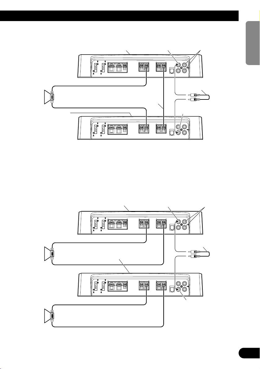
Two Amplifier (Ex. Bridge)
• Only use speakers having an impedance of 2 Ω to 16 Ω. In addition, in the case of connecting multiple
speakers with a bridge, check that the synthetic impedance is at least 2 Ω.
• The setting of the POWER MODE switch varies according to the speaker impedance. Slide the POWER
MODE switch to the HI-CURRENT position if the impedance is from 2 Ω to less than 4 Ω, or slide it to the
NORMAL position if the impedance is from 4 Ω to 16 Ω. The same setting is used for both amplifiers.
• When switching to the SYNC INV mode, the seal over the MODE SELECT switch must be peeled off and
you can find SYNC INV switch. Peel off the seal after checking that connections are correct.
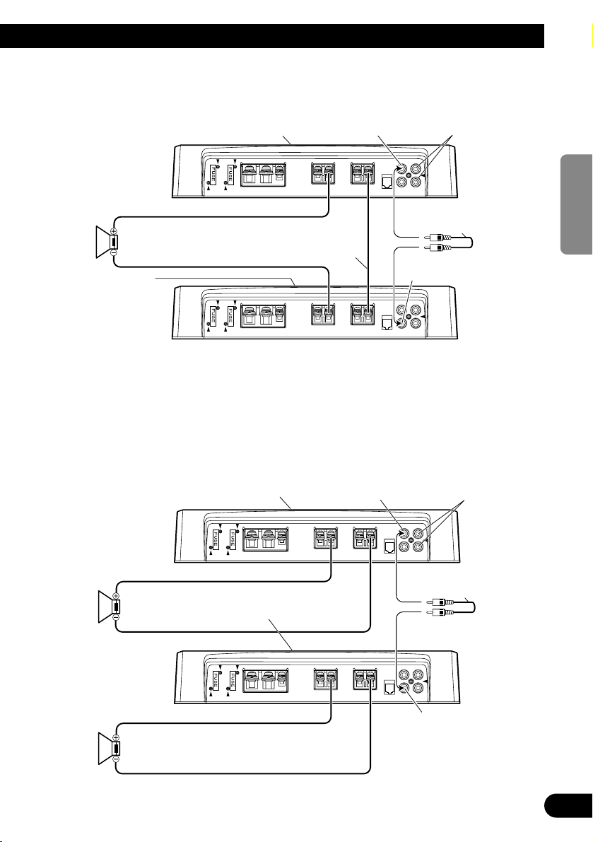
Two Amplifier
• Use speakers having an impedance from 1 Ω to 8 Ω.
• The setting of the POWER MODE switch varies according to the speaker impedance. See the “Setting the
Unit” section for details. The same setting is used for both amplifiers.
MODE SELECT switch
must be in SYNC INV
position.
Connecting wire with RCA
pin plugs (sold separately).
Connecting
speaker wire
(sold separately).
MODE SELECT switch
must be in SYNC position.
MODE SELECT switch must
be in MASTER position.
Connect to a car stereo.
For details, see the
“Connection Diagram”.
2 Ω to 16 Ω
1 Ω to 8 Ω
1 Ω to 8 Ω
SYNC OUTPUT
MODE SELECT switch must
be in MASTER position.
Connect to a car stereo.
For details, see the
“Connection Diagram”.
Connecting wire with RCA
pin plugs (sold separately).
SYNC INPUT
SYNC OUTPUT
SYNC INPUT
Page 12
11
Connecting the Unit
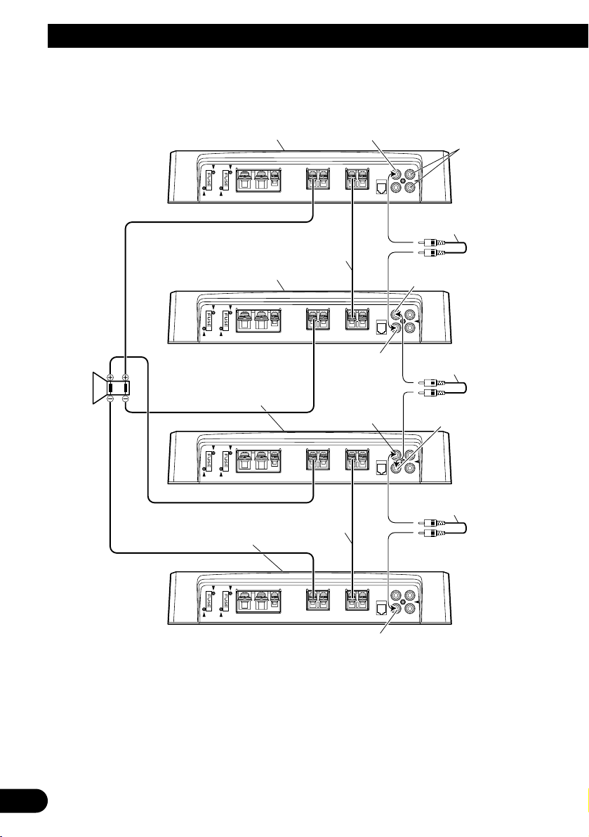
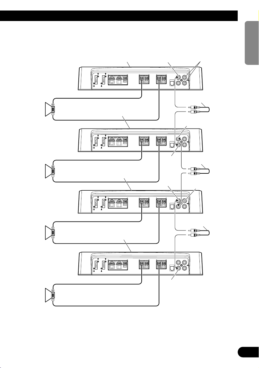
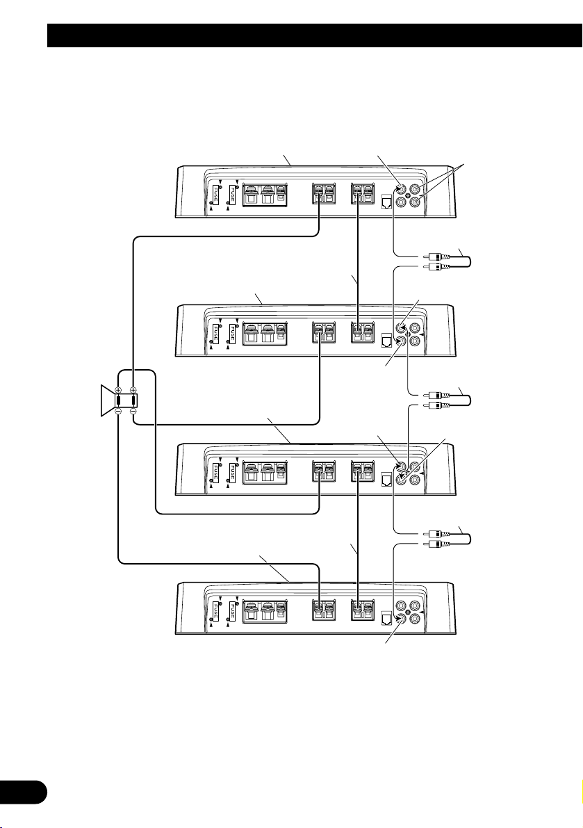
Four Amplifier (Ex. Bridge)
MODE SELECT switch
must be in MASTER position.
Connecting wire with RCA
pin plugs (sold separately).
MODE SELECT switch must
be in SYNC INV position.
Connect to a car stereo.
For details, see the
“Connection Diagram”.
MODE SELECT switch must be
in SYNC INV position.
MODE SELECT switch must
be in SYNC INV position.
Connecting wire with RCA
pin plugs (sold separately).
Connecting wire with RCA
pin plugs (sold separately).
Connecting speaker
wire (sold separately).
Connecting speaker
wire (sold separately).
SYNC OUTPUT
SYNC INPUT
SYNC OUTPUT
SYNC INPUT
2 Ω to
16 Ω
• Only use speakers having an impedance of 2 Ω to 16 Ω. In addition, in the case of connecting multiple
speakers with a bridge, check that the synthetic impedance is at least 2 Ω.
• The setting of the POWER MODE switch varies according to the speaker impedance. Slide the POWER
MODE switch to the HI-CURRENT position if the impedance is from 2 Ω to less than 4 Ω, or slide it to the
NORMAL position if the impedance is from 4 Ω to 16 Ω. The same setting is used for four amplifiers.
• When switching to the SYNC INV mode, the seal over the MODE SELECT switch must be peeled off and
you can find SYNC INV switch. Peel off the seal after checking that connections are correct.
SYNC OUTPUT
SYNC INPUT
Page 13
12
ENGLISH
ESPAÑOL
DEUTSCH
FRANÇAIS
ITALIANO
NEDERLANDS
кмллдав
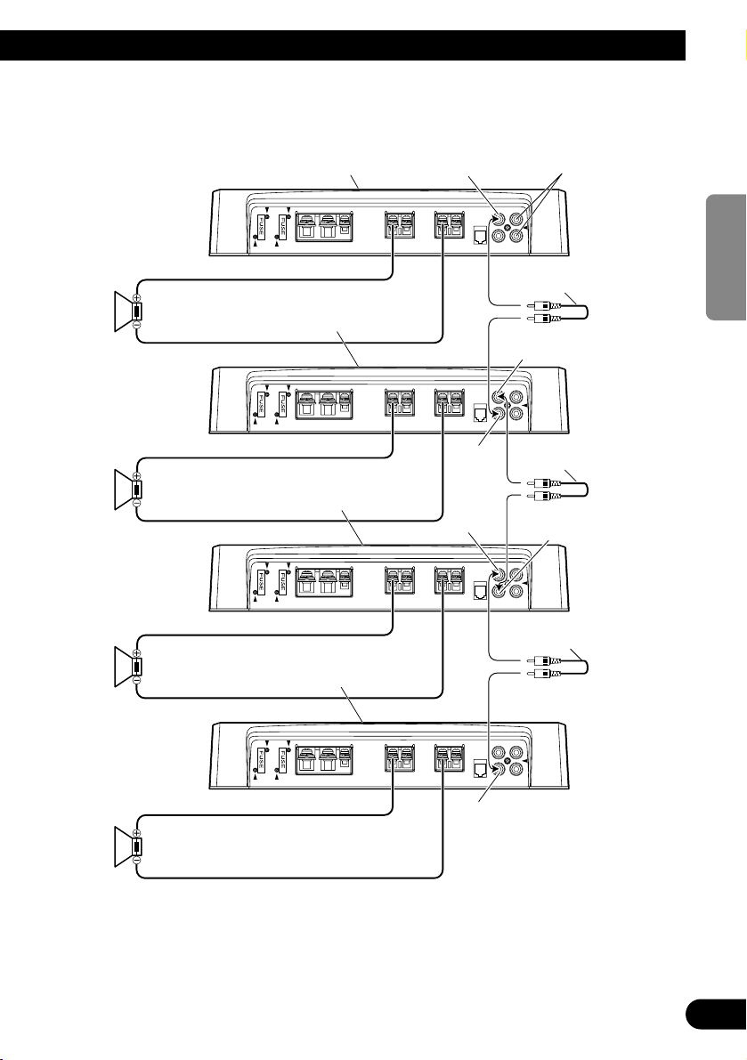
Four Amplifier
MODE SELECT switch
must be in MASTER position.
Connect to a car stereo.
For details, see the
“Connection Diagram”.
Connecting wire with RCA
pin plugs (sold separately).
Connecting wire with RCA
pin plugs (sold separately).
Connecting wire with RCA
pin plugs (sold separately).
MODE SELECT switch
must be in SYNC position.
MODE SELECT switch
must be in SYNC position.
MODE SELECT switch
must be in SYNC position.
1 Ω to 8 Ω
1 Ω to 8 Ω
1 Ω to 8 Ω
1 Ω to 8 Ω
SYNC OUTPUT
SYNC
INPUT
SYNC
OUTPUT
SYNC INPUT
• Use speakers having an impedance from 1 Ω to 8 Ω.
• The setting of the POWER MODE switch varies according to the speaker impedance. See the “Setting the
Unit” section for details. The same setting is used for four amplifiers.
SYNC OUTPUT
SYNC INPUT
Page 14

13
Installation
CAUTION
• Do not install in:
—Places where it could injure the driver or pas-
sengers if the vehicle stops suddenly.
—Places where it may interfere with the driver,
such as on the floor in front of the driver’s
seat.
• Make sure that wires are not caught in the sliding
mechanism of the seats, resulting in a short-circuit.
• Confirm that no parts are behind the panel when
drilling a hole for installation of the amplifier.
Protect all cables and important equipment such
as fuel lines, brake lines and electrical wiring
from damage.
• Install tapping screws in such a way that the
screw tip does not touch any wire. This is important to prevent wires from being cut by vibration
of the car, which can result in fire.
• DO NOT allow amplifier to come into contact
with liquids due to, for example, the location
where the amplifier is installed. Electrical shock
could result. Also, amplifier and speaker damage,
smoke, and overheating could result from contact
with liquids. In addition, the amplifier surface and
the surface of any attached speakers could
become hot to the touch and minor burns could
result.
• To ensure proper installation, use the supplied
parts in the manner specified. If any parts other
than the supplied ones are used, they may damage
internal parts of the amplifier, or they may
become loose causing the amplifier to shut down.
• Never replace the fuse with one of greater value
or rating than the original fuse. Use of an improper fuse could result in overheating and smoke and
could cause damage to the product and injury
including burns.
CAUTION:
To prevent malfunction and/or injury
• To ensure proper heat dissipation of the amplifier,
be sure of the following during installation.
—Allow adequate space above the amplifier for
proper ventilation.
—Do not cover the amplifier with a floor mat or
carpet.
• DO NOT allow amplifier to come into contact
with liquids due to, for example, the location
where the amplifier is installed. Electrical shock
could result. Also, amplifier and speaker damage,
smoke, and overheating could result from contact
with liquids. In addition, the amplifier surface and
the surface of any attached speakers could
become hot to the touch and minor burns could
result.
• Do not install the amplifier on unstable places
such as the spare tire board.
• The best location for installation differs with the
car model and installation location. Secure the
amplifier at a sufficiently rigid location.
• Make temporary connections first and check that
the amplifier and the system operate properly.
• After installing the amplifier, confirm that the
spare tire, jack and tools can be easily removed.
Page 15
14
ENGLISH
ESPAÑOL
DEUTSCH
FRANÇAIS
ITALIANO
NEDERLANDS
кмллдав
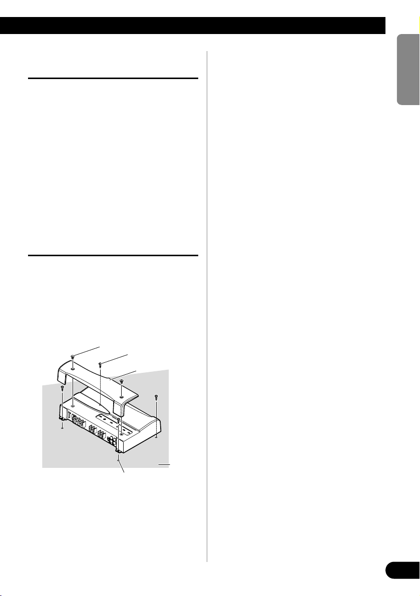
Example of installation on the floor
mat or on the chassis
1. Place the amplifier where it is to be
installed. Insert the supplied tapping screws (4 × 18 mm) into the
screw holes. Push on the screws with
a screwdriver so they make marks
where the installation holes are to
be located.
2. Drill 2.5 mm diameter holes at the
point marked, and install the amplifier, either on the carpet or directly
to the chassis.
Replacing the terminal cover
1. Align the unit and terminal cover,
and insert the screw.
2. Tighten the screw with a 4 mm
hexagonal wrench.
Drill a 2.5 mm diameter hole
Tapping-screws
(4 × 18 mm)
Floor mat
or chassis
Screw
Terminal Cover
Page 16

15
Specifications
Power source ........................................................................................................ 14.4 V DC (10.8 V to 15.1 V allowable)
Grounding system .......................................................................................................................................... Negative type
Current consumption ........................................................................................................ 39 A (at continuous power, 4 Ω)
Average current drawn* .......................................................................................................... 12 A (4 Ω for one channel)
20 A (2 Ω for one channel)
28 A (1 Ω for one channel)
Fuse (external) ........................................................................................................................................................ 40 A × 2
Dimensions ...................................................................................................................... 304 (W) × 56 (H) × 202 (D) mm
Weight .................................................................................................................... 3.0 kg (Leads for wiring not included)
Maximum power output ................................................................................ 800 W × 1 (4 Ω) / 1 200 W × 1 (1 Ω to 2 Ω)
Continuous power (14.4 V) ...................................... NORMAL mode: 4 Ω, 20 Hz to 240 Hz, 1.0% THD, 400 W × 1
2 Ω, 100 Hz, 1.0% THD, 600 W × 1
HI-CURRENT mode: 4 Ω, 20 Hz to 240 Hz, 1.0% THD, 150 W × 1
2 Ω, 100 Hz, 1.0% THD, 300 W × 1
1 Ω, 100 Hz, 1.0% THD, 600 W × 1
Load impedance ........................................................................................................................ 4 Ω (1 Ω to 8 Ω allowable)
Frequency response .......................................................................................................... 10 Hz to 240 Hz (+0 dB, –3 dB)
S/N ratio ........................................................................................................................................ 92 dB (IEC-A network)
Distortion .......................................................................................................................................... 0.5 % (10 W, 100 Hz)
Low pass filter ............................................................................................................ Cut off frequency: 40 Hz to 240 Hz
Cut off slope: –18 dB/oct
Subsonic filter (HPF) .............................................................................................................................. Frequency: 20 Hz
Slope: –18 dB
Bass boost ................................................................................................................................................ Frequency: 50 Hz
Level: 0 / 6 / 9 / 12 dB
Gain control .................................................................................................................................... RCA: 400 mV to 6.5 V
SP: 1.6 V to 26 V
Maximum input level / impedance ...................................................................................................... RCA: 6.5 V / 22 kΩ
SP: 26 V / 90 kΩ
Note:
• Specifications and the design are subject to possible modification without notice
due to improvements.
*Average current drawn
• The average current drawn is nearly the maximum current drawn by this unit
when an audio signal is input. Use this value when working out total current
drawn by multiple power amplifiers.
Page 17

16
ENGLISH
ESPAÑOL
DEUTSCH
FRANÇAIS
ITALIANO
NEDERLANDS
кмллдав
Page 18

1
Antes de usar este producto .................... 1
Registro del producto ........................................ 1
En caso de desperfectos .................................... 2
Sobre este producto .......................................... 2
PRECAUCION ................................................ 2
ADVERTENCIA .............................................. 2
Ajuste de esta unidad .............................. 3
Cubierta de terminales ...................................... 3
Indicador de alimentación ................................ 3
Interruptor selector subsónico .......................... 3
Control de refuerzo de graves .......................... 3
Interruptor BFC
(Control de la frecuencia de batido) .......... 3
Interruptor MODE SELECT ............................ 4
Control de ganancia .......................................... 4
Control de frecuencia de corte para LPF .......... 4
Interruptor de entrada ........................................ 4
Interruptor POWER MODE .............................. 4
Conexión de la unidad .............................. 5
Diagrama de conexión ...................................... 6
Conexión del terminal de alimentación ............ 7
Conexión del terminal de salida de altavoz ...... 8
Uso de la entrada de altavoz .............................. 8
Conexión de los cables de altavoces ................ 9
Instalación ................................................ 13
Ejemplo de instalación en la alfombra
del piso o en el chasis .............................. 14
Recolocación de la cubierta de terminales ...... 14
Especificaciones .................................... 15
Muchas gracias por la adquisición de este
producto PIONEER. Antes de tratar de
operarlo, lea atentamente este manual.
Las viviendas privadas en los 25 estados
miembros de la UE, en Suiza y Noruega
pueden devolver gratuitamente sus productos electrónicos usados en las instalaciones
de recolección previstas o bien en las
instalaciones de minoristas (si adquieren
un producto similar nuevo).
En el caso de los países que no se han
mencionado en el párrafo anterior, póngase en contacto con sus autoridades
locales a fin de conocer el método de eliminación correcto.
Al actuar siguiendo estas instrucciones, se
asegurará de que el producto de desecho se
somete a los procesos de tratamiento, recuperación y reciclaje necesarios, con lo que
se previenen los efectos negativos potenciales para el entorno y la salud humana.
Registro del producto
Visítenos en el siguiente sitio:
Registre su producto. Conservaremos los
datos de su compra archivados para que
pueda consultar esta información en caso
de que deba efectuar un reclamo a la
compañía de seguros por pérdida o robo.
Si desea deshacerse de este
producto, no lo mezcle con
los residuos generales de su
hogar. De conformidad con la
legislación vigente, existe un
sistema de recogida distinto
para los productos
electrónicos que requieren un
procedimiento adecuado de
tratamiento, recuperación y
reciclado.
Contenido Antes de usar este producto
Page 19

ENGLISH
ESPAÑOL
DEUTSCH
FRANÇAIS
ITALIANO
NEDERLANDS
кмллдав
2
En caso de desperfectos
Si esta unidad no funciona correctamente,
póngase en contacto con su distribuidor o
con el Centro de Servicio PIONEER
autorizado más cercano.
Sobre este producto
Este producto es un amplificador para
altavoz de subgraves. Si ambos los canales
L (izquierdo) y R (derecho) se conectan a
la entrada RCA de este producto, la salida
se mezcla ya que este producto es un
amplificador monofónico.
PRECAUCION
No reemplace nunca el fusible por uno con
un valor de régimen mayor que el fusible
original. El uso de un fusible inadecuado
podría causar el sobrecalantamiento o
humo, así como podría causar daños al
producto y lesiones, incluyendo
quemaduras.
ADVERTENCIA
• Siempre utilice el cable de batería rojo especial y
los cables de tierra ([RD-223] y [RD-222]), vendidos separadamente. Conecte el cable de batería
directamente al terminal positivo de la batería del
vehículo (+) y el cable de tierra a la carrocería del
vehículo. Existe el riesgo de quemado del fusible
si se conecta solamente uno de ellos.
• No toque en el amplificador con las manos
mojadas. Caso contrario, usted puede llevar un
choque eléctrico. Igualmente, no toque en el
amplificador cuando esté mojado.
• Para seguridad del tráfico y para mantener condiciones de conducción seguras, mantenga el volumen suficientemente bajo de manera que aun se
pueda escuchar el sonido del tráfico normal.
• Verifique las conexiones del suministro de
energía y altavoces para ver si el fusible del cable
de batería vendido separadamente o el fusible del
amplificador se queman. Detecte la causa y solucione el problema, y reemplace el fusible con un
otro del mismo tamaño y régimen.
• Para evitar mal funcionamiento del amplificador
y altavoces, el circuito de protección cortará la
alimentación al amplificador (el sonido se
detendrá) cuando se produzca una situación anormal. En tal caso, apague el sistema y verifique la
conexión de la alimentación y altavoces. Detecte
la causa y resuelva el problema.
• Contacte a su distribuidor si no puede detectar la
causa.
• Para evitar choques eléctricos o cortocircuitors
durante la conexión e instalación, asegúrese de
desconectar el terminal negativo (–) de la batería
antes de proceder.
• Confirme que ninguna parte quede detrás del
panel, cuando perfore un orificio para la instalación del amplificador. Asegúrese de proteger
todos los cables y equipos importantes, tales
como líneas de combustibles, líneas de frenos y el
cableado eléctrico.
• NO permita que el amplificador entre en contacto
con líquidos debido a, por ejemplo, la localización donde el amplificador esté instalado. Esto
podría causar una sacudida eléctrica. El contacto
con líquidos también podría causar daños y
sobrecalentamiento al amplificador e altavoces.
Además, la superficie del amplificador y la superficie de cualquier altavoz instalado también
podrían ponerse muy calientes al tacto, pudiendo
causar pequeñas quemaduras.
Page 20
3
Ajuste de esta unidad
Indicador de
alimentación
El indicador de
alimentación se
ilumina cuando la
unidad se encuentra
activada.
Cubierta de terminales
Antes de montar la unidad, desapriete los
tornillos con una llave hexagonal de 4 mm y
quite la cubierta de terminales.
Interruptor BFC (Control de la
frecuencia de batido)
El interruptor BFC se encuentra en la parte inferior
de la unidad. Si se oye un batido durante la escucha
de una transmisión MW/LW con el equipo estéreo
de automóvil, cambie el interruptor BFC
utilizando un destornillador pequeño.
Control de refuerzo de
graves
Se puede seleccionar un nivel de
refuerzo de graves de 0, 6, 9 y
12 dB.
Para las instrucciones acerca de la
conexión del control remoto de
refuerzo de graves al amplificador,
consulte la sección “Diagrama de
conexión”.
Interruptor selector subsónico
El filtro subsónico corta las frecuencias inaudibles inferiores a 20 Hz,
para eliminar las vibraciones indeseables y minimizar la pérdida de
potencia.
Page 21

ENGLISH
ESPAÑOL
DEUTSCH
FRANÇAIS
ITALIANO
NEDERLANDS
кмллдав
4
Control de ganancia
Si el nivel del sonido está muy bajo, aún cuando se aumenta el volumen del equipo estéreo
para automóvil usado con este amplificador de potencia, gire a la derecha el control de ganancia. Si hay distorsión del sonido cuando se aumenta el volumen del equipo estéreo de
automóvil, gire los controles a la izquierda.
• Cuando se usa un estéreo de automóvil equipado con RCA (salida estándar de 500 mV), ajuste a la posición NORMAL. Cuando use con un estéreo de automóvil Pioneer equipado con RCA con una
salida máxima de 4 V o más, ajuste el nivel para adecuarse al nivel de salida del estéreo del automóvil.
•
Si se oye ruido excesivo cuando se usan los terminales de entrada de altavoz, gire el control de nivel a la izquierda.
Interruptor de entrada
Es posible introducir desde la salida exterior de un equipo estéreo de automóvil o desde la salida
de altavoz de un equipo estéreo de automóvil. Cambie el interruptor de entrada antes de encender
la unidad. Como cambiar el interruptor de entrada con la unidad encendida puede generar un ruido
alto por los altavoces, la unidad se apaga por una función de protección. Cuando utilice una salida
exterior, deslice el interruptor hacia la izquierda. Para las instrucciones de instalación, consulte la
sección “Diagrama de conexión”. Cuando utilice una salida de altavoz, deslice el interruptor hacia
la derecha. En este caso, es necesario utilizar el hilo de entrada de altavoz suministrado con el
cable con conector RCA. Para los detalles, consulte la sección “Uso de la entrada de altavoz”.
Control de frecuencia de corte para LPF
Se puede seleccionar una frecuencia de corte de 40 Hz a 240 Hz.
Interruptor MODE SELECT
Puede seleccionar el modo de sincronización de amplificador entre MASTER, SYNC y SYNC INV.
Ajuste el interruptor MODE SELECT a la posición MASTER cuando utilice un amplificador solamente.
Cuando utilice en sincronismo, conectando dos o más amplificadores en combinación, ajuste el primer
amplificador a MASTER, y ajuste los amplificadores restantes a SYNC o SYNC INV de acuerdo con la
forma en que estén conectados. La única vez que se cambia el amplificador al modo SYNC INV es
cuando los amplificadores están conectados sincrónicamente con el puente externo.
Cuando cambie el modo SYNC INV, debe quitar el sello sobre el interruptor MODE SELECT y podrá
encontrar el interruptor SYNC INV. Quite el sello después de comprobar que las conexiones estén correctas. Consulte la sección “Conexión de los hilos de altavoz” para los detalles sobre el interruptor
MODE SELECT.
Interruptor POWER MODE
Cuando utilice altavoces con una impedancia sintética de 2 a 8 Ω, deslice el interruptor hacia la
derecha (NORMAL). Cuando utilice altavoces con una impedancia sintética de 1 Ω a menos de
2 Ω, deslice el interruptor hacia la izquierda (HI-CURRENT). Esas configuraciones se utilizan
solamente cuando se utiliza un único amplificador. Consulte la sección “Conexión de los hilos
de altavoz” cuando combine varios amplificadores.
Si la impedancia de los altavoces excede de 2 Ω (4 Ω cuando utilice el puente externo), mientras se pueda ajustar el interruptor POWER MODE a la posición HI-CURRENT, ajustar a la
posición NORMAL permite el disfrute de un sonido de alta potencia.
Page 22
5
Conexión de la unidad
PRECAUCION
• Quite el terminal negativo (–) de la batería para
evitar riesgo de cortocircuitos y daño a la unidad.
• Asegure el alambrado con abrazaderas de cable o
cinta adhesiva. Para proteger el alambrado,
envuelva cinta adhesiva alrededor de ellos en
donde contacta con partes metálicas.
• No tienda cables por donde puedan calentarse,
por ejemplo donde el calentador sople sobre ellos.
Si la aislación se calienta, podría resultar dañada,
resultando en cortocircuito a través de la carrocería del vehículo.
• Asegúrese que los alambres no interfieran con
partes móviles del vehículo como la palanca de
cambios, el freno de mano o el mecanismo de
deslizamiento de los asientos.
• No corte ningún cable. De otra manera, el circuito
de protección podría no funcionar cuando
debiera.
• Nunca alimente otro equipo cortando la aislación
del cable de alimentación y conectándolo al
cable. La capacidad de corriente del cable será
excedida, causando sobrecalentamiento.
• No reemplace nunca el fusible por uno con un
valor de régimen mayor que el fusible original. El
uso de un fusible inadecuado podría causar el
sobrecalantamiento o humo, así como podría
causar daños al producto y lesiones, incluyendo
quemaduras.
PRECAUCION:
Para evitar daños y/o lesiones
• No conecte a tierra (masa) el cable del altavoz
directamente ni conecte un cable negativo (–) a
varios altavoces.
• Esta unidad es para vehículos con una batería de
12 voltios y terminal negativo a tierra. Antes de
instalar en un vehículo de recreación, camión u
ómnibus, verifique el voltaje de la batería.
• Si el sistema estereofónico del coche está funcionando por un largo período de tiempo mientras el
motor permanece inactivo o en marcha al ralentí,
la batería puede agotarse. Apague el estéreo de
automóvil cuando el motor se encuentre funcionando en marcha al ralenté o permanece in activo.
• Si el cable del control remoto del sistema del
amplificador se conecta al terminal de alimentación a través del interruptor de encendido
(12 V de CC), el amplificador estará siempre activado cuando el encendido está activado, sin considerar de si el estéreo de automóvil se encuentra
activado o desactivado. Debido a esto, la batería
puede agotarse si deja el motor funcionando en
marcha al ralentí o permanece inactivo.
• NO conecte un altavoz de subgraves con una
impedancia inferior a la especificada en la sección “Conexión de la unidad”. Una conexión no
especificada podría causar daños, desprendimiento de humo y sobrecalentamiento del amplificador. La superficie del amplificador también
podría ponerse caliente al tacto y esto podría
resultar en quemaduras ligeras.
• Conecte uno de los tres altavoces de subgraves al
amplificador; 1: un altavoz de subgraves con una
entrada nominal de 420 W o mayor y una impedancia de 4 Ω, 2: un altavoz con una entrada nominal de 600 W y una impedancia de 2 Ω o 3: un
altavoz con una entrada nominal de 600 W y una
impedancia de 1 Ω. Si la entrada nominal y la
impedancia están fuera de los rangos arriba, el
altavoz de subgraves puede incendiarse, emitir
humo o averiarse.
• Instale y coloque el cable de batería vendido separadamente lo más alejado posible de los cables de
los altavoces. Instale y coloque el cable de batería
y cable de tierra vendidos separadamente, los
cables de los altavoces, y el amplificador lo más
alejados posible de la antena, cable de antena y
sintonizador.
• Los cables para esta unidad y aquéllas para las
unidades pueden ser de colores diferentes aun si
tienen la misma función. Cuando se conecta esta
unidad a otra, refiérase a los manuales de instalación de ambas unidades y conecte los cables
que tienen la misma función.
Page 23
ENGLISH
ESPAÑOL
DEUTSCH
FRANÇAIS
ITALIANO
NEDERLANDS
кмллдав
6
Diagrama de conexión
•
Este diagrama muestra las conexiones utilizando la salida exterior. Deslice el interruptor de entrada hacia la izquierda.
•
En el caso de conectar la salida externa de un equipo estéreo de automóvil a una entrada RCA, utilice la tomada para la salida de gama completa. La razón para esto es que no se puede desactivar el LPF del amplificador.
Si no se puede utilizar esta toma, conecte la tomada de salida el altavoz de subgraves a la entrada RCA.
• Cuando conecte con la salida de altavoz, las conexiones difieren de las indicadas en el diagrama. Para los
detalles, consulte la sección “Uso de la entrada de altavoz”. En cualquier caso, se requiere ajustar el
interruptor de entrada. Para los detalles, consulte la sección “Ajuste de esta unidad”.
•
Siempre utilice el cable de batería rojo especial y los cables de tierra ([RD-223] y [RD-222]), vendidos separadamente. Conecte el cable de batería directamente al terminal positivo de la batería del vehículo (+) y el cable de
tierra a la carrocería del vehículo. Existe el riesgo de quemado del fusible si se conecta solamente uno de ellos.
Fusible (40 A)
Estéreo de
automóvil con
tomas con conector
de salida RCA
Salida externa
Conexión de cable con los
enchufes de conector RCA
(en venta por separado).
Tomas de conector de
entrada RCA
Cable del control remoto del sistema (en venta por separado)
Conecte el terminal macho de este hilo al terminal de control remoto de sistema del
equipo estéreo para automóvil (SYSTEM REMOTE CONTROL). El terminal hembra puede ser
conectado al terminal de control del relé de antena. Si el estéreo de automóvil no tiene un terminal de
control remoto del sistema, conecte el terminal macho al terminal de alimentación a través del
interruptor de encendido.
Terminal de salida de
altavoz
Vea la sección “Conexión
de los cables de altavoces”
para las instrucciones de
conexión del altavoz.
Toma para el control
remoto de refuerzo de
graves Conecte esta toma
y el control remoto de
refuerzo de graves con el
hilo de control remoto de
refuerzo de graves.
Control remoto de
refuerzo de graves
Hilo de control
remoto de refuerzo
de graves
6 m
Ojal
Cable de batería rojo especial
Después de realizar todas las conexiones al amplificador,
conecte el terminal del conductor de batería del amplificador al terminal positivo (+) de la batería.
Cable de puesta a tierra (negro)
Conecte a una carrocería metálica o chasis.
Fusible (30 A) × 3
[RD-223]
(en venta por separado)
[RD-222] (en venta por separado)
Toma SYNC OUTPUT / SYNC INPUT
Consulte la sección “Conexión de los
cables de altavoces” para las instrucciones
de conexión de la toma SYNC OUTPUT /
SYNC INPUT.
Page 24
7
Conexión de la unidad
Conexión del terminal de
alimentación
• Siempre utilice el cable de batería rojo especial y
los cables de tierra ([RD-223] y [RD-222]), vendidos separadamente. Conecte el cable de batería
directamente al terminal positivo de la batería del
vehículo (+) y el cable de tierra a la carrocería del
vehículo. Existe el riesgo de quemado del fusible
si se conecta solamente uno de ellos.
1. Pase el cable de batería desde el
compartimiento del motor al interior del vehículo.
• Luego de hacer todas las otras conexiones al
amplificador, conecte el terminal del conductor de batería del amplificador al terminal
positivo (+) de la bateria.
[RD-223]
[RD-222]
2. Tuerza el cable de batería, cable de
puesta a tierra y cable de control
remoto del sistema.
3. Fije las orejetas a los extremos de
los cables. Orejetas no suministrados.
• Utilice alicates, etc. para plegar las orejetas a
los cables.
4. Conecte los cables al terminal.
• Fijar los cables firmemente utilizando los
tornillos para terminales.
ADVERTENCIA
Dejar de apretar firmemente el cable de puesta a
tierra al terminal usando los tornillos para terminales
podría causar el sobrecalentamiento del área de los
terminales, así como podría causar daños y lesiones
incluyendo pequeñas quemaduras.
Terminal GND
Terminal
POWER
Cable de batería
Terminal de control
remoto del sistema
Cable del control
remoto del sistema
Cable de puesta
a tierra
Cable de batería
Cable de
puesta a tierra
Tuérzala
Orejeta
Orejeta
Fusible (30 A)
Compartimiento del
motor
Interior del
vehículo
Perfore un orificio de 14 mm en
la carrocería del
vehículo.
Inserte el ojal de caucho
de la junta tórica en la
corrocería del vehículo.
Terminal positivo
Fusible (30 A)
Fusible (30 A)
Compartimiento del
motor
Interior del
vehículo
Perfore un orificio de 8 mm en
la carrocería del
vehículo.
Inserte el ojal de caucho
de la junta tórica en la
corrocería del vehículo.
Terminal positivo
Page 25
ENGLISH
ESPAÑOL
DEUTSCH
FRANÇAIS
ITALIANO
NEDERLANDS
кмллдав
Conexión del terminal de salida
de altavoz
1. Desnude la extremidad de los cables
de altavoces utilizando alicates o
una tajadera por aproximadamente
10 mm y tuérzala.
2. Fije las orejetas a los extremos de
los cables de altavoz. Orejetas no
suministrados.
• Utilice alicates, etc. para plegar las orejetas a
los cables.
3. Conecte los cables de altavoz al terminal de salida de altavoz.
• Fije los cables firmemente utilizando los
tornillos para terminales.
Uso de la entrada de altavoz
Conecte los hilos de salida de altavoz del
equipo estéreo de automóvil al amplificador utilizando el hilo de entrada de
altavoz suministrado con el cabo con
conector RCA.
•
Deslice el interruptor de entrada hacia la derecha.
7 Conexiones cuando se utiliza la
entrada de altavoz
• Cuando se conecta el hilo de salida de altavoz del
equipo estéreo de automóvil al amplificador, el
amplificador se enciende automáticamente
cuando se enciende el equipo estéreo de
automóvil. En este caso, no es necesario conectar
el hilo de control remoto de sistema.
• Si se conecta el amplificador y la unidad principal
con un hilo de entrada de altavoz con cable de
clavija RCA, sólo se puede encender el amplificador cuando se está utilizando otro amplificador.
Si dos o más amplificadores están conectados
sincrónicamente en combinación, conecte la
unidad principal y todos los amplificadores con el
hilo de control remoto de sistema.
Nota:
• Conecte el hilo de control remoto de sistema
cuando el amplificador no se enciende cuando se
enciende el equipo estéreo de automóvil.
10 mm
8
Tuérzala
Cable de altavoz
Orejeta
Cable de altavoz
Torrillo de terminal
Terminal de
salida de
altavoz
Salida de altavoz
Equipo estéreo
de automóvil
A la toma de
entrada RCA
de esta unidad.
Hilo de entrada de
altavoz con cable
con conector RCA
Blanco: Negro: Negro: Rojo:
Izquierda + Izquierda ≠ Derecha ≠ Derecha +
Page 26
9
Conexión de la unidad
Conexión de los cables de altavoces
Conecte los hilos de altavoz y ajuste el interruptor MODE SELECT y el interruptor POWER MODE de acuerdo con
la configuración que se utilice refiriéndose a las figuras que se muestran a continuación y en la página siguiente.
• Cuando conecte sincrónicamente dos o más amplificadores en combinación, utilice solamente estos amplificadores. No mezcle estos amplificadores con otros amplificadores.
• Cuando conecte sincrónicamente dos o más amplificadores en combinación, ajuste el control de ganancia,
interruptor de selección subsónica, control de frecuencia de corte para LPF y control de refuerzo de graves
en el amplificador que ha ajustado a MASTER con el interruptor MODE SELECT. Estas configuraciones
se desactivan cuando se ajusta un amplificador a SYNC o SYNC INV.
PRECAUCION
NO instale o use este amplificador mediante la conexión de los cables de las bocinas de 2 Ω nominales (o
menos) en paralelo para lograr un modo en puente de 1 Ω (o menos) (Diagrama B).
Realizar un puente incorrecto podría resultar en un sobrecalentamiento y daño del amplificador, así como
en un desprendimiento de humo del mismo. La superficie del amplificador podría también ponerse
caliente al tacto y resultar en quemaduras ligeras.
Para instalar o usar adecuadamente el modo de puente y lograr una carga de 2 Ω, conecte los cables de
dos bocinas de 4 Ω en paralelo con Izquierdo + y Derecho – (Diagrama A), o use una sola bocina de 2 Ω.
Si la impedancia sintética es de 2 Ω a menos de 4 Ω, asegúrese siempre de ajustar el introducir POWER
MODE a la posición HI-CURRENT.
Además, consulte el manual de instrucciones de los altavoces para más información sobre el procedimiento correcto de conexión.
Amplificador simple
• Utilice altavoces con una impedancia de 1 Ω a 8 Ω.
• El ajuste del interruptor POWER MODE varía de acuerdo con la impedancia de los altavoces. Para los
detalles, consulte la sección “Ajuste de esta unidad”.
El interruptor MODE SELECT
debe estar en la posición MASTER.
Conecte a un equipo estéreo
de automóvil. Para los detalles, consulte
la sección “Diagrama de conexión”.
Diagrama A - Correcto
Diagrama B - Incorrecto
Altavoz
de 4
Ω
Altavoz
de 4 Ω
Altavoz
de 2 Ω
Altavoz
de 2 Ω
1 Ω a 8 Ω
Modo de conexión en
puente de 2 Ω
Modo de conexión en
puente de 1 Ω
Page 27
10
ENGLISH
ESPAÑOL
DEUTSCH
FRANÇAIS
ITALIANO
NEDERLANDS
кмллдав
Dos amplificadores (Puente externo)
• Utilice solamente altavoces con una impedancia de 2 Ω a 16 Ω. Además, en el caso de conectar múltiples
altavoces con un puente, compruebe que la impedancia sintética sea de por lo menos 2 Ω.
• El ajuste del interruptor POWER MODE varía de acuerdo con la impedancia de los altavoces. Deslice el
interruptor POWER MODE a la posición HI-CURRENT si la impedancia es de 2 Ω a menos de 4 Ω, o
deslícelo a la posición NORMAL si la impedancia es de 4 Ω a 16 Ω. Se utiliza la misma configuración para
ambos amplificadores.
• Cuando cambie el modo SYNC INV, debe quitar el sello sobre el interruptor MODE SELECT y podrá
encontrar el interruptor SYNC INV. Quite el sello después de comprobar que las conexiones estén correctas.
Dos amplificadores
• Utilice altavoces con una impedancia de 1 Ω a 8 Ω.
•
El ajuste del interruptor POWER MODE varía de acuerdo con la impedancia de los altavoces. Para los detalles,
consulte la sección “Ajuste de esta unidad”. Se utiliza la misma configuración para ambos amplificadores.
El interruptor MODE SELECT
debe estar en la posición MASTER.
El interruptor MODE SELECT
debe estar en la posición MASTER.
Conecte a un equipo estéreo de
automóvil. Para los detalles, consulte
la sección “Diagrama de conexión.
El interruptor MODE
SELECT debe estar en
la posición SYNC INV.
El interruptor MODE SELECT
debe estar en la posición SYNC.
Conexión del cable con
enchufes de clavijas RCA
(vendidos separadamente).
Conexión del cable de altavoz
(vendido separadamente).
SYNC OUTPUT
Conexión del cable con
enchufes de clavijas RCA
(vendidos separadamente).
2 Ω a 16 Ω
SYNC INPUT
SYNC OUTPUT
SYNC INPUT
1 Ω a 8 Ω
1 Ω a 8 Ω
Conecte a un equipo estéreo de
automóvil. Para los detalles, consulte
la sección “Diagrama de conexión”.
Page 28
Cuatro amplificadores (Puente externo)
• Utilice solamente altavoces con una impedancia de 2 Ω a 16 Ω. Además, en el caso de conectar múltiples
altavoces con un puente, compruebe que la impedancia sintética sea de por lo menos 2 Ω.
• El ajuste del interruptor POWER MODE varía de acuerdo con la impedancia de los altavoces. Deslice el
interruptor POWER MODE a la posición HI-CURRENT si la impedancia es de 2 Ω a menos de 4 Ω, o
deslícelo a la posición NORMAL si la impedancia es de 4 Ω a 16 Ω. Se utiliza la misma configuración para
los cuatro amplificadores.
• Cuando cambie el modo SYNC INV, debe quitar el sello sobre el interruptor MODE SELECT y podrá
encontrar el interruptor SYNC INV. Quite el sello después de comprobar que las conexiones estén correctas.
11
Conexión de la unidad
El interruptor MODE
SELECT debe estar en la
posición SYNC INV.
El interruptor MODE SELECT
debe estar en la posición SYNC INV.
El interruptor MODE SELECT
debe estar en la posición SYNC INV.
Conexión
del cable de
altavoz
(vendido
separadamente).
Conexión del
cable de altavoz
(vendido
separadamente).
El interruptor MODE SELECT
debe estar en la posición MASTER.
Conecte a un equipo
estéreo de automóvil. Para
los detalles, consulte
la sección “Diagrama de
conexión”.
Conexión del cable con enchufes
de clavijas RCA (vendidos
separadamente).
Conexión del cable con
enchufes de clavijas RCA
(vendidos separadamente).
Conexión del cable con enchufes
de clavijas RCA (vendidos
separadamente).
2 Ω a 16 Ω
SYNC OUTPUT
SYNC INPUT
SYNC OUTPUT
SYNC INPUT
SYNC OUTPUT
SYNC INPUT
Page 29
Cuatro amplificadores
• Utilice altavoces con una impedancia de 1 Ω a 8 Ω.
• El ajuste del interruptor POWER MODE varía de acuerdo con la impedancia de los altavoces. Para los
detalles, consulte la sección “Ajuste de esta unidad”. Se utiliza la misma configuración para los cuatro
amplificadores.
12
ENGLISH
ESPAÑOL
DEUTSCH
FRANÇAIS
ITALIANO
NEDERLANDS
кмллдав
El interruptor MODE SELECT
debe estar en la posición MASTER.
Conecte a un equipo estéreo
de automóvil.
Para los detalles, consulte la
sección “Diagrama de conexión”.
Conexión del cable con enchufes de
clavijas RCA (vendidos separadamente).
Conexión del cable con enchufes de
clavijas RCA (vendidos separadamente).
Conexión del cable con enchufes de
clavijas RCA (vendidos separadamente).
El interruptor MODE SELECT
debe estar en la posición SYNC.
El interruptor MODE SELECT
debe estar en la posición SYNC.
El interruptor MODE SELECT
debe estar en la posición SYNC.
1 Ω a 8 Ω
1 Ω a 8 Ω
1 Ω a 8 Ω
1 Ω a 8 Ω
SYNC OUTPUT
SYNC
INPUT
SYNC
OUTPUT
SYNC INPUT
SYNC OUTPUT
SYNC INPUT
Page 30

13
Instalación
PRECAUCION
• No lo instale en:
—Donde podría lesionar al conductor o a los
pasajeros si se detiene el vehículo bruscamente.
—Donde podría interferir con el conductor,
como por ejemplo en el piso en frente al
asiento del conductor.
• Asegúrese que los cables no se enganchen en el
mecanismo deslizante de los asientos, resultando
en cortocircuito.
• Confirme que ninguna parte quede detrás del
panel, cuando perfore un orificio para la instalación del amplificador. Asegúrese de proteger
todos los cables y equipos importantes, tales
como líneas de combustibles, líneas de frenos y el
cableado eléctrico.
• Instale los tornillos de conexión de manera tal que
la punta del tornillo no toque ningún cable. Esto
es importante para evitar que los cables se corten
por vibración del automóvil, lo que podría causar
un incendio.
• NO permita que el amplificador entre en contacto
con líquidos debido a, por ejemplo, la localización
donde el amplificador esté instalado. Esto podría
causar una sacudida eléctrica. El contacto con
líquidos también podría causar daños y sobrecalentamiento al amplificador e altavoces. Además,
la superficie del amplificador y la superficie de
cualquier altavoz instalado también podrían ponerse muy calientes al tacto, pudiendo causar
pequeñas quemaduras.
• Para asegurar una instalación apropiada, utilice
las partes suministradas de la manera especificada. Si se utiliza cualquier otra parte que no sean
las suministradas, puede dañarse las partes internas del amplificador, o pueden aflojarse y el
amplificador puede dejar de funcionar.
• No reemplace nunca el fusible por uno con un
valor de régimen mayor que el fusible original. El
uso de un fusible inadecuado podría causar el
sobrecalantamiento o humo, así como podría
causar daños al producto y lesiones, incluyendo
quemaduras.
PRECAUCION:
Para evitar fallas de funcionamiento y/o
lesiones
• Para asegurar la disipación de calor apropriada del
amplificador, cuide de lo siguiente durante la
instalación.
—Permita un espacio adecuado en la parte
superior del amplificador para una ventilación apropiada.
—No cubra el amplificador con la cubierta de
piso o alfombra.
• NO permita que el amplificador entre en contacto
con líquidos debido a, por ejemplo, la localización
donde el amplificador esté instalado. Esto podría
causar una sacudida eléctrica. El contacto con
líquidos también podría causar daños y sobrecalentamiento al amplificador e altavoces. Además,
la superficie del amplificador y la superficie de
cualquier altavoz instalado también podrían ponerse muy calientes al tacto, pudiendo causar
pequeñas quemaduras.
• No instale el amplificador sobre superficies
inestables como el tablero del neumático de
repuesto.
• Confirme que ninguna parte quede detrás del
panel, cuando perfore un orificio para la instalación del amplificador. Asegúrese de proteger
todos los cables y equipos importantes, tales
como líneas de combustibles, líneas de frenos y el
cableado eléctrico.
• Realice primero conexiones provisorias y compruebe que el amplificador y el sistema operan
adecuadamente.
• Para asegurar una instalación apropiada, utilice
las partes suministradas de la manera especificada. Si se utiliza cualquier otra parte que no sean
las suministradas, puede dañarse las partes internas del amplificador, o pueden aflojarse y el
amplificador puede dejar de funcionar.
Page 31

14
ENGLISH
ESPAÑOL
DEUTSCH
FRANÇAIS
ITALIANO
NEDERLANDS
кмллдав
Ejemplo de instalación en la
alfombra del piso o en el chasis
1. Ubique el amplificador en la posición en donde va a ser instalado.
Inserte los tornillos autoterrajantes
suministrados (4 × 18 mm) en los
orificios de los tornillos. Presione los
tornillos con un destornillador de
modo que puedan dejar puntos
marcados de la posición en donde
irán los orificios para la instalación.
2. Perfore orificios de 2,5 mm de
diámetro en el punto marcado, e
instale el amplificador, ya sea en la
alfombra o directamente en el
chasis.
Recolocación de la cubierta de
terminales
1. Alinee la unidad y la cubierta de
terminales, e inserte el tornillo.
2. Apriete el tornillo con una llave
hexagonal de 4 mm.
Perfore un orificio de 2,5 mm
de diámetro
Tornillos autoterrajantes
(4 × 18 mm)
Alfombra
del piso o
chasis
Tornillo
Cubierta de terminales
Page 32

15
Especificaciones
Alimentación .................................................................................... 14,4 V CC (10,8 V a 15,1 V permisible)
Sistema de puesta a tierra .......................................................................................................... Tipo negativo
Consumo de corriente ...................................................................................... 39 A (potencia continua, 4 Ω)
Consumo de corriente promedio* .......................................................................... 12 A (4 Ω para uno canal)
20 A (2 Ω para uno canal)
28 A (1 Ω para uno canal)
Fusible (externo) ................................................................................................................................ 40 A × 2
Dimensiones .............................................................................................. 304 (An) × 56 (Al) × 202 (Pr) mm
Peso ........................................................................ 3,0 kg (No se incluyen los conductores para el cableado)
Potencia de salida máxima .......................................................... 800 W × 1 (4 Ω) / 1 200 W × 1 (1 Ω a 2 Ω)
Potencia continua (14,4 V) .................... Modo NORMAL: 4 Ω, 20 Hz a 240 Hz, 1,0% THD, 400 W × 1
2 Ω, 100 Hz, 1,0% THD, 600 W × 1
Modo HI-CURRENT: 4 Ω, 20 Hz a 240 Hz, 1,0% THD, 150 W × 1
2 Ω, 100 Hz, 1,0% THD, 300 W × 1
1 Ω, 100 Hz, 1,0% THD, 600 W × 1
Impedancia de carga .............................................................................................. 4 Ω (1 Ω a 8 Ω permisible)
Respuesta de frecuencia ................................................................................ 10 Hz a 240 Hz (+0 dB, –3 dB)
Relación S/N .................................................................................................................... 92 dB (rede IEC-A)
Distorsión ...................................................................................................................... 0,5% (10 W, 100 Hz)
Filtro de paso bajo .................................................................................. Frecuencia de corte: 40 Hz a 240 Hz
Pendiente de corte: –18 dB/oct
Filtro subsónico (HPF) ........................................................................................................ Frecuencia: 20 Hz
Pendiente: –18 dB
Intensificación de los graves .............................................................................................. Frecuencia: 50 Hz
Nivel: 0 / 6 / 9 / 12 dB
Control de ganancia ...................................................................................................... RCA: 400 mV a 6,5 V
SP: 1,6 V a 26 V
Impedancia / nivel de entrada máxima .......................................................................... RCA: 6,5 V / 22 kΩ
SP: 26 V / 90 kΩ
Nota:
• Las especificaciones y el diseño están sujetos a posibles modificaciones sin previo
aviso debido a mejoramientos.
*Consumo de corriente promedio
• El consumo de corriente promedio es casi el consumo de corriente máximo de esta
unidad, cuando se ingresa una señal de audio. Utilice este valor cuando tenga que
trabajar con la corriente total consumida por múltiples amplificadores de potencia.
Page 33

16
ENGLISH
ESPAÑOL
DEUTSCH
FRANÇAIS
ITALIANO
NEDERLANDS
кмллдав
Page 34

1
Vor Gebrauch dieses Produkts ................ 1
Produktregistrierung .......................................... 1
Im Störungsfall .................................................. 2
Über dieses Produkt .......................................... 2
VORSICHT ...................................................... 2
WARNUNG ...................................................... 2
Einstellen dieses Geräts .......................... 3
Anschlussabdeckung ........................................ 3
Stromanzeige .................................................... 3
Subsonic-Wahlschalter ...................................... 3
Bassverstärkungsregler ...................................... 3
Interferenzschutzschalter (BFC) ........................ 3
MODE SELECT-Schalter ................................ 4
Verstärkungsregelung ........................................ 4
Ausschaltfrequenz-Regelung für LPF .............. 4
Eingangsschalter ................................................ 4
Power Mode-Schalter ........................................ 4
Anschluss der Einheit .............................. 5
Anschlussschema .............................................. 6
Anschluss der Stromversorgung ........................ 7
Anschluss der Lautsprecher-Ausgang-
Klemmen .................................................... 8
Benutzung des Lautsprecher-Eingangs ............ 8
Anschließen der Lautsprecherkabel .................. 9
Einbau ........................................................ 13
Beispiel eines Einbaus auf einer
Bodenmatte oder auf dem Rahmen .......... 14
Wiederanbringen der Anschlussabdeckung .... 14
Technische Daten .................................... 15
Vielen Dank für den Kauf dieses
PIONEER Produkts. Diese
Bedienungsanleitung vor der Inbetriebnahme
sorgfältig durchlesen.
Privathaushalte in den 25 Mitgliedsstaaten
der EU, in der Schweiz und in Norwegen
können ihre gebrauchten elektronischen
Produkte an vorgesehenen
Sammeleinrichtungen kostenfrei zurückgeben oder aber an einen Händler zurückgeben (wenn sie ein ähnliches neues
Produkt kaufen).
Bitte wenden Sie sich in den Ländern, die
oben nicht aufgeführt sind, hinsichtlich der
korrekten Verfahrensweise der Entsorgung
an die örtliche Kommunalverwaltung.
Auf diese Weise stellen Sie sicher, dass
das zu entsorgende Produkt der notwendigen Behandlung, Rückgewinnung und
Wiederverwertung unterzogen wird, und
so mögliche negative Einflüsse auf die
Umwelt und die menschliche Gesundheit
vermieden werden.
Produktregistrierung
Besuchen Sie uns auf folgender Website:
Registrieren Sie Ihr Produkt. Wir speichern
die Detaildaten Ihres Produktkaufs in einer
Datei, sodass wir Ihnen diese Informationen
bei Verlust oder Diebstahl des Produkts
jederzeit für Ihre Versicherung bereitstellen
können.
Mischen Sie dieses Produkt,
wenn Sie es entsorgen
wollen, nicht mit
gewöhnlichen
Haushaltsabfällen. Es gibt ein
getrenntes Sammelsystem für
gebrauchte elektronische
Produkte, über das die
richtige Behandlung,
Rückgewinnung und
Wiederverwertung gemäß der
bestehenden Gesetzgebung
gewährleistet wird.
Inhaltsverzeichnis Vor Gebrauch dieses Produkts
Page 35

ENGLISH
ESPAÑOL
DEUTSCH
FRANÇAIS
ITALIANO
NEDERLANDS
кмллдав
2
Im Störungsfall
Bei Betriebsstörungen den Händler oder eine
PIONEER-Kundendienststelle kon-sultieren.
Über dieses Produkt
Bei diesem Produkt handelt es sich um
einen Verstärker für den Subwoofer.
Wenn sowohl der linke (L) als auch rechte
(R) Kanal mit dem RCA-Eingang dieses
Produkts verbunden ist, wird der Ausgang
gemischt, da es sich bei diesem Produkt
um einen Mono-Verstärker handelt.
VORSICHT
Ersetzen Sie die Sicherung niemals durch
eine mit einem größeren Wert bzw.
Nennwert, als die ursprüngliche Sicherung
hatte. Der Gebrauch einer falschen Sicherung
kann zu Heißlauf, Rauchentwicklung,
Beschädigung des Produkts, Verbrennungen
und anderen Verletzungen führen.
WARNUNG
• Nur das getrennt erhältliche rote Spezial-Batterieund Massekabel ([RD-223] und [RD-222]) verwenden. Das Batteriekabel direkt an den Pluspol
(+) der Wagenbatterie und das Massekabel an
Karosseriemasse anschließen. Wenn nur einer
dieser Anschlüsse vorgenommen wird, kann eine
Sicherung durchbrennen.
• Fassen Sie den Verstärker nicht mit nassen
Händen an, da Sie anderenfalls einen elektrischen
Schlag erleiden können. Berühren Sie den
Verstärker auch nicht, wenn dieser nass ist.
• Lassen Sie die Lautstärke so eingestellt, dass Sie
beim Fahren noch Verkehrsgeräusche hören
können. Es ist gefährlich, ein Fahrzeug zu führen,
ohne Verkehrsgeräusche von außen hören zu
können.
• Die Anschlüsse der Stromversorgung und der
Lautsprecher überprüfen, wenn die Sicherung des
getrennt erhältlichen Batteriekabels oder die
Verstärker-Sicherung durchbrennt. Machen Sie
die Ursache ausfindig, beheben Sie die Störung,
und ersetzen Sie die Sicherung dann durch eine
andere mit derselben Größe und demselben
Nennwert.
• Zur Vermeidung von Schäden am Verstärker und
den Lautsprechern unterbricht eine
Schutzschaltung automatisch die
Stromversorgung zum Verstärker (der Klang setzt
aus), sobald ein anormaler Betriebszustand
eintritt. Stellen Sie den Betriebsschalter in diesem
Fall auf OFF, und überprüfen Sie die
Stromversorgungs- und Lautsprecheranschlüsse.
Ermitteln Sie die Ursache des Problems und
schaffen Sie umgehend Abhilfe.
• Wenden Sie sich bitte an Ihren Fachhändler, falls
sich die Ursache der Störung nicht klären lässt.
• Trennen Sie zur Vermeidung von elektrischen
Schlägen und Kurzschlüssen bei der
Inbetriebnahme des Gerätes vorher unbedingt das
Anschlusskabel vom negativen (–) Batteriepol ab.
• Überzeugen Sie sich, dass sich keine Teile hinter
der Konsole befinden, wenn Sie ein Loch zum
Einbau des Verstärkers bohren. Achten Sie
darauf, dass alle Kabel und wichtigen Teile wie
Benzin- und Bremsleitungen und die elektrischen
Kabelbäume geschützt sind.
• ACHTEN Sie darauf, dass der Verstärker NICHT
mit Flüssigkeiten in Berührung kommen kann,
zum Beispiel wegen eines ungünstigen
Einbauplatzes. Ein elektrischer Schlag könnte die
Folge sein. Berührung mit Flüssigkeiten kann
auch zu einer Beschädigung von Verstärker und
Lautsprechern, sowie zu Rauchbildung und
Überhitzung führen. Außerdem können
Oberflächen von Verstärker und jeglicher
angebrachter Lautsprecher heiß werden, sodass
bei Berührung kleinere Verbrennungen
verursacht werden könnten.
Page 36

3
Einstellen dieses Geräts
Stromanzeige
Die Stromanzeige
leuchtet auf, wenn die
Stromversorgung
eingeschaltet wird.
Interferenzschutzschalter
(BFC)
Der BFC-Schalter befindet sich an der
Unterseite des Geräts. Falls Sie bei
MW/LW-Empfang mit Ihrer AutoStereoanlage Hintergrundgeräusche
vernehmen, stellen Sie den BFCSchalter mithilfe eines kleinen
Schraubendrehers ein.
Anschlussabdeckung
Vor der Installation lösen Sie die
Schrauben mit einem 4-mmSechskantschlüssel und nehmen Sie die
Anschlussabdeckung ab.
Bassverstärkungsregler
Als Bassverstärkungspegel können Sie
entweder 0, 6, 9 oder 12 dB wählen.
Anweisungen zum Anschluss der
Bassverstärkungs-Fernbedienung an den
Verstärker finden Sie im Abschnitt
“Anschlussschema”.
Subsonic-Wahlschalter
Der Subsonic-Filter beschneidet nicht
hörbare Frequenzen unter 20 Hz, um
ungewünschte Vibrationen zu eliminieren
und Leistungsverluste zu minimieren.
Page 37

ENGLISH
ESPAÑOL
DEUTSCH
FRANÇAIS
ITALIANO
NEDERLANDS
кмллдав
4
Verstärkungsregelung
Wenn die Lautstärke zu schwach ist, selbst wenn der Lautstärkeregler der zusammen mit
diesem Leistungsverstärker verwendeten Auto-Stereo-Anlage aufgedreht wird, drehen Sie den
Verstärkungsregler im Uhrzeigersinn. Falls Klangverzerrungen auftreten, wenn die Lautstärke
aufgedreht wird, drehen Sie den Verstärkungsregler im Gegenuhrzeigersinn.
• Bei Gebrauch mit einer mit RCA ausgestatteten Auto-Stereoanlage (Standard-Ausgang 500 mV) auf
die Position NORMAL einstellen. Bei Gebrauch mit einer mit RCA ausgestatteten Pioneer-AutoStereoanlage mit einem maximalen Ausgang von 4 V oder mehr den Pegel dem Auto-StereoanlagenAusgangspegel anpassen.
• Falls bei Gebrauch der Lautsprecher-Eingangsbuchsen zu starke Störungen auftreten, den
Verstärkungsregler im Gegenuhrzeigersinn drehen.
Eingangsschalter
Eingang von einem externen Auto-Stereo-Ausgang oder einem Auto-Stereo-LautsprecherAusgang ist möglich. Stellen Sie den Eingangsschalter ein, bevor Sie den Strom einschalten.
Da Umstellen des Eingangsschalters bei eingeschaltetem Strom ein lautes
Lautsprechergeräusch verursachen kann, wird der Strom durch eine Schutzfunktion
abgeschaltet. Zur Verwendung eines externen Ausgangs legen Sie den Schalter nach links.
Bezüglich Anschlussanweisungen siehe Abschnitt “Anschlussschema”. Zur Verwendung
eines Lautsprecher-Ausgangs legen Sie den Schalter nach rechts. In diesem Fall muss das
mitgelieferte Lautsprecher-Eingangskabel mit RCA-Stiftkabel verwendet werden. Genaueres
hierzu finden Sie im Abschnitt “Benutzung des Lautsprecher-Eingangs”.
Ausschaltfrequenz-Regelung für LPF
Sie können eine Ausschaltfrequenz zwischen 40 Hz und 240 Hz wählen.
MODE SELECT-Schalter
Als Verstärker-Synchronisationsmodus kann MASTER, SYNC oder SYNC INV gewählt
werden. Wenn nur ein Verstärker verwendet wird, stellen Sie den MODE SELECT-Schalter
auf die Position MASTER. Bei Synchronverbindung von Verstärkern, zwei oder mehr kombiniert, stellen Sie den ersten Verstärker auf MASTER, die anderen auf SYNC oder SYNC
INV, je nach Anschlussweise. Verstärkerschaltung auf den Modus SYNC INV erfolgt nur
dann, wenn Verstärker synchron mit der ex. Brücke verbunden sind.
Zum Schalten auf den Modus SYNC INV muss das Siegel über dem MODE SELECT Schalter
abgezogen werden, um Zugang zum SYNC INV-Schalter zu erhalten. Ziehen Sie das Siegel
ab, nachdem Sie sich vergewissert haben, dass die Anschlüsse stimmen. Einzelheiten zum
MODE SELECT-Schalter finden Sie im Abschnitt “Anschließen der Lautsprecherkabel”.
POWER MODE-Schalter
Bei Gebrauch von Lautsprechern mit einer synthetischen Impedanz von 2 Ω bis 8 Ω legen Sie
den Schalter nach rechts (NORMAL). Bei Gebrauch von Lautsprechern mit einer synthetischen Impedanz von 1 Ω bis weniger als 2 Ω legen Sie den Schalter nach links (HI-CURRENT).
Diese Einstellungen werden nur bei Gebrauch eines einzelnen Verstärkers verwendet. Bei
kombiniertem Einsatz mehrerer Verstärker siehe unter "Anschließen der Lautsprecherkabel".
Wenn die Lautsprecherimpedanz 2 Ω (4 Ω bei Gebrauch von ex. Brücke) überschreitet,
ermöglicht die Position NORMAL High Power-Sound, obwohl der POWER MODE-Schalter
auf die Position HI-CURRENT eingestellt sein kann.
Page 38

5
Anschluss der Einheit
VORSICHT:
Zur Vermeidung von Schäden und/oder
Verletzungen
• Keinesfalls das Lautsprecherkabel direkt erden
oder einen negativen Anschluss (–) für mehrere
Lautsprecher gleichzeitig anschließen.
• Dieses Gerät ist für Fahrzeuge mit einer 12 Volt
Batterie und negativer Erdung bestimmt. Vor
dem Einbau in ein Freizeitfahrzeug, Laster oder
Bus, die Spannung der Batterie überprüfen.
• Wenn die Autostereoanlage längere Zeit
eingeschaltet bleibt, während der Motor nicht
oder nur im Leerlauf läuft, so könnte dies zu einer
Entladung der Batterie führen. Schalten Sie Ihr
Stereogerät aus, wenn der Motor im Leerlauf oder
im Stillstand ist.
• Sollte die System-Fernbedienungskabel des
Verstärkers am Stromanschluss über den
Zündungsschalter angeschlossen sein
(12 V Gleichspannung), so ist der Verstärker
immer eingeschaltet, wenn die Zündung
eingeschaltet wird, unabhängig davon, ob das
Stereogerät ein- oder ausgeschaltet ist. In diesem
Fall könnte es zu einer Entladung der Batterie
kommen, wenn der Motor im Stillstand oder im
Leerlauf betrieben wird.
• Schließen Sie KEINEN Subwoofer mit einer
niedrigeren Impedanz als im Abschnitt
“Anschluss der Einheit” angegeben an. Ein
Anschluss, der nicht den Spezifikationen
entspricht, kann zu einer Beschädigung,
Rauchabgabe und Überhitzung des Verstärkers
führen. Außerdem kann die Oberfläche des
Verstärkers heiß werden und bei Berührung
leichte Verbrennungen verursachen.
• Schließen Sie einen der genannten drei
Subwoofer an den Verstärker an; 1: einen
Subwoofer mit einem Nenneingang von 420 W
oder höher und mit einer Impedanz von 4 Ω, 2:
einen Subwoofer mit einem Nenneingang von
600 W oder höher und mit einer Impedanz von 2
Ω oder 3: einen Subwoofer mit einem
Nenneingang von 600 W oder höher und mit
einer Impedanz von 1 Ω. Wenn Nenneingang und
Impedanz außerhalb dieser Bereiche liegen, kann
der Subwoofer zu brennen beginnen, Rauch
abgeben, oder beschädigt werden.
• Das getrennt erhältliche Batteriekabel installieren
und möglichst weit von den Lautsprecherkabeln
entfernt verlegen. Getrennt erhältliches
Batteriekabel, Massekabel, Lautsprecherkabel
und Verstärker möglichst weit von Antenne,
Antennenkabel und Tuner entfernt
installieren/verlegen.
• Kabel dieses Geräts und die anderer Geräte
können unterschiedliche Farben haben, auch
wenn sie die gleichen Funktionen haben. Beim
Anschluss dieses Geräts an ein anderes Gerät
unter Bezugnahme auf die mit beiden Geräten
mitgelieferten Installationsanleitungen die Kabel
mit derselben Funktion verbinden.
VORSICHT
• Trennen Sie das Batterieanschlusskabel vom
negativen (–) Batteriepol, um Kurzschlüsse und
Schäden am Gerät zu vermeiden.
• Befestigen Sie die Kabel mit Kabelklemmen oder
Klebeband. Kabel, die Kontakt mit Metallteilen
haben, sollten an den betreffenden Stellen mit
Klebeband isoliert werden.
• Vermeiden Sie beim Verlegen der Kabel Plätze,
an denen die Kabel Wärmeeinwirkung ausgesetzt
sind, wie z.B. in der Nähe der Heizung. Derartige
Wärmeeinwirkung kann zu einer Beschädigung
der Kabelisolierung und schließlich zu
Kurzschlüssen über die Fahrzeugkarosserie führen.
• Achten Sie darauf, dass keines der Kabel
bewegliche Fahrzeugteile, wie z.B. den
Schalthebel, die Handbremse oder den
Sitzverstellhebel, behindert.
• Kürzen Sie die Kabel nicht. Gekürzte Kabel
können einen Ausfall der Schutzschaltung
verursachen.
• Leiten Sie niemals Strom an andere Geräte,
indem Sie die lsolierung des
Spannungsversorgungskabels dieses Gerätes
freilegen und anzapfen. Die hieraus resultierende
Überschreitung der
Spannungsbelastungskapazität des Kabels hat
Überhitzung zur Folge.
• Ersetzen Sie die Sicherung niemals durch eine
mit einem größeren Wert bzw. Nennwert, als die
ursprüngliche Sicherung hatte. Der Gebrauch
einer falschen Sicherung kann zu Heißlauf,
Rauchentwicklung, Beschädigung des Produkts,
Verbrennungen und anderen Verletzungen
führen.
Page 39

ENGLISH
ESPAÑOL
DEUTSCH
FRANÇAIS
ITALIANO
NEDERLANDS
кмллдав
6
Anschlussschema
• Dieses Schema zeigt die Anschlüsse für externen Ausgang. Legen Sie den Eingangsschalter nach links.
• Für den Anschluss des externen Ausgangs von einer Auto-Stereoanlage an einen RCA-Eingang verwenden
Sie die Buchse für Vollbereichsausgang. Der Grund hierfür ist, dass das LPF des Verstärkers nicht ausgeschaltet werden kann. Wenn diese Buchse nicht verwendet werden kann, verbinden Sie die SubwooferAusgangsbuchse mit dem RCA-Eingang.
• Bei Verbindung mit Lautsprecher-Ausgang unterscheiden sich die Anschlüsse von denen dieses Schemas.
Genaueres hierzu finden Sie im Abschnitt “Benutzung des Lautsprecher-Eingangs”. Der Eingangsschalter
muss in jedem Fall eingestellt werden. Genaueres hierzu finden Sie im Abschnitt “Einstellen dieses Geräts”.
• Nur das spezielle rote Batteriekabel und Massekabel ([RD-223] und [RD-222]) (Sonderzubehör) verwenden. Das Batteriekabel direkt an den Pluspol (+) der Wagenbatterie und das Massekabel an
Karosseriemasse anschließen. Wenn nur einer dieser Anschlüsse vorgenommen wird, kann eine Sicherung
durchbrennen.
Sicherung (30 A) × 3
Tülle
Spezielles rotes Batteriekabel
Nachdem alle anderen Anschlüsse am Verstärker
ausgeführt worden sind, das Batterie-Kabelklemme des
Verstärkers mit der positiven (+) Klemme der Batterie
verbinde.
Erdungskabel (schwarz)
An Fabrzeugkarosserie oder Metallteil anschließen.
Sicherung (40 A)
Autostereo mit
RCAAusgangsbuchsen
Externer Ausgang
Anschlusskabel mit RCAStiftsteckern (separat
erhältlich).
System-Fernbedienungskabel (separat erhältlich)
Den Stecker dieses Kabels an die System-Fernbedienungsbuchse der Auto-Stereoanlage anschließen
(SYSTEM REMOTE CONTROL). Die Buchse kann am Auto-Antennen-Relais-Anschluss angeschlossen
werden. Sollte die Stereoanlage nicht über einen Fernbedienung-System-Regler-Anschluss verfügen,
schließen Sie das Steckteil am Stromanschluss des Zündschalters an.
Lautsprecher-Ausgangsklemme
Siehe Abschnitt: “Anschließen
der Lautsprecherkabel” für
Einzelheiten bezüglich des
Lautsprecheranschlusses.
SYNC OUTPUT / SYNC INPUT-Buchse
Bezüglich Anweisungen zur Belegung der
SYNC OUTPUT / SYNC INPUT-Buchse
siehe Abschnitt “Anschließen der
Lautsprecherkabel”.
Buchse für die BassverstärkungsFernbedienung
Schließen Sie das BassverstärkungsFernbedienungskabel an diese
Buchse und an die BassverstärkungsFernbedienung an.
BassverstärkungsFernbedienung
BassverstärkungsFernbedienungskabel
6 m
[RD-223]
(separat erhältlich)
[RD-222] (separat erhältlich)
RCA-Eingangsbuchsen
Page 40

7
Anschluss der Einheit
Anschluss der Stromversorgung
• Nur das spezielle rote Batteriekabel und
Massekabel ([RD-223] und [RD-222])
(Sonderzubehör) verwenden. Das Batteriekabel
direkt an den Pluspol (+) der Wagenbatterie und
das Massekabel an Karosseriemasse anschließen.
Wenn nur einer dieser Anschlüsse vorgenommen
wird, kann eine Sicherung durchbrennen.
1. Führen Sie das Batteriekabel vom
Motorraum in den Fahrgastraum.
• Nachdem alle Verkabelungen am Verstärker
ausgeführt worden sind, verbinden Sie die
Batterie-Kabelklemme des Verstärkers mit
der positiven (+) Klemme der Batterie.
[RD-223]
[RD-222]
2. Verdrillen Sie Batteriekabel,
Massekabel und SystemFernbedienungskabel.
3. Bringen Sie Kabelschuhe an den
Kabelenden an. Kontaktzungen
nicht mitgeliefert.
• Mit einer Zange o.Ä. die Kontaktzungen am
Draht festklemmen.
4. Die Drähte an die Klemme
anschließen.
• Beftestigen Sie die Drähte sicher mit den
Klemmenschrauben.
WARNUNG
Wenn das Batteriekabel mit den Klemmenschrauben
nicht richtig befestigt wird, kann der
Klemmenbereich heiß werden, wodurch Schäden
und Verletzungen, wie Verbrennungen, verursacht
werden können.
Zusammendrehen
Kontaktzunge
Kontaktzunge
Batteriekabel
Erdungskabel
GND-Anschluss
Stromversorgung
Batteriekabel
System-Fernbedienungsanschluss
System-Fernbedienungskabel
Erdungskabel
Sicherung (30 A)
Innere des
Fahrzeugs
Bohren Sie ein
Loch mit einem
Durchmesser von
8 mm in den
Fahrzeugrahmen.
Setzen Sie die O-RingGummidich-tung in den
Fahrzeugrahmen ein.
Pluspol
Motorraum
Sicherung (30 A)
Innere des
Fahrzeugs
Bohren Sie ein
Loch mit einem
Durchmesser von
14 mm in den
Fahrzeugrahmen.
Setzen Sie die O-RingGummidich-tung in den
Fahrzeugrahmen ein.
Pluspol
Sicherung (30 A)
Motorraum
Page 41

ENGLISH
ESPAÑOL
DEUTSCH
FRANÇAIS
ITALIANO
NEDERLANDS
кмллдав
Anschluss der LautsprecherAusgang-Klemmen
1. Die Enden der Lautsprecherkabel
um ca. 10 mm mit einer Kneifzange
oder einem Schneider abisolieren
und die Kabelenden
zusammendrehen.
2. Bringen Sie Kabelschuhe an den
Enden der Lautsprecherkabel an.
Kontaktzungen nicht mitgeliefert.
• Mit einer Zange o.Ä. die Kontaktzungen am
Draht festklemmen.
3.
Schließen Sie die
Lautsprecherkabel an die
Lautsprecherausgangklemmen an.
• Die Lautsprecherdrähte fest mit den
Klemmenschrauben befestigen.
Benutzung des LautsprecherEingangs
S
chließen Sie die Auto-Stereo-LautsprecherAusgangskabel mithilfe des mitgelieferten
Lautsprecher-Eingangskabels mit RCAStiftkabel an den Verstärker an.
• Legen Sie den Eingangsschalter nach rechts.
7 Anschlüsse bei Benutzung des
Lautsprecher-Eingangs
• Bei Anschluss des Auto-Stereo-LautsprecherAusgangskabels am Verstärker wird dieser
automatisch eingeschaltet, wenn die AutoStereoanlage eingeschaltet wird. In diesem Fall
erübrigt sich der Anschluss des SystemFernbedienungskabels.
• Falls Verstärker und Hauptgerät mit einem
Lautsprechereingangskabel mit RCA-Stiftkabel
verbunden sind, wird der Verstärkerstrom nur
dann eingeschaltet, wenn ein Verstärker verwendet wird. Bei Synchronverbindung von
Verstärkern, zwei oder mehr kombiniert,
schließen Sie das Hauptgerät und alle Verstärker
mit dem Systemfernbedienungskabel an.
Hinweis:
• Schließen Sie das System-Fernbedienungskabel
an, wenn der Verstärker nicht automatisch mit der
Auto-Stereoanlage eingeschaltet wird.
10 mm
8
Zusammendrehen
Lautsprecherkabel
Kontaktzunge
LautsprecherAusgangklemme
Lautsprecherkabel
Klemmenschraube
LautsprecherAusgang
LautsprecherEingangskabel
mit RCAStiftkabel
An RCAEingangsbuchse
dieses Geräts.
Auto-Stereo
Weiß: Schwarz: Schwarz: Rot:
Links + Links ≠ Rechts ≠ Rechts +
Page 42

9
Anschluss der Einheit
Anschließen der Lautsprecherkabel
Schließen Sie die Lautsprecherkabel so an, und stellen Sie die Schalter MODE SELECT sowie POWER
MODE so ein, wie es der gewünschten Konfiguration gemäß den unten und auf der nächsten Seite gezeigten
Abbildungen entspricht.
• Bei Synchronverbindung von Verstärkern, zwei oder mehr kombiniert, verwenden Sie nur diese Verstärker.
Setzen Sie diese Verstärker nicht gleichzeitig mit anderen Verstärkern ein.
• Bei Synchronverbindung von Verstärkern, zwei oder mehr kombiniert, stellen Sie Verstärkungsregler,
Subsonic-Wahlschalter, Grenzfrequenzregler für LPF und Bassverstärkungsregler an dem Verstärker ein,
der mit dem MODE SELECT-Schalter auf MASTER geschaltet worden ist. Bei einem auf SYNC oder
SYNC INV geschalteten Verstärker können diese Einstellungen nicht vorgenommen werden.
VORSICHT
Diesen Verstärker NICHT mit parallel verdrahteten Lautsprechern mit einer Nennimpedanz von 2 Ω (oder
darunter) einbauen oder verwenden, um einen Überbrückungsmodus von 1 Ω (oder darunter) zu erzielen
(Diagramm B).
Falsche Überbrückung kann den Verstärker beschädigen und zu Rauchbildung und Überhitzung führen.
Außerdem kann die Oberfläche des Verstärkers heiß werden und beim Anfassen leichte Verbrennungen verursachen.
Für korrekte Installation oder Verwendung eines Überbrückungsmodus und Erzielung einer 2-Ω-Last, verdrahten Sie zwei 4-Ω-Lautsprecher parallel mit Links + und Rechts – (Diagramm A), oder verwenden Sie
einen einzelnen 2-Ω-Lautsprecher.
Wenn die synthetische Impedanz zwischen 2 Ω und weniger als 4 Ω liegt, vergewissern Sie sich
stets, dass der POWER MODE-Schalter auf die Position HI-CURRENT eingestellt ist.
Lesen Sie außerdem in der Lautsprecheranleitung nach, wie der Anschluss vorzunehmen ist.
Einzelverstärker
• Verwenden Sie Lautsprecher mit einer Impedanz zwischen 1 Ω und 8 Ω.
• Die Einstellung des POWER MODE-Schalters hängt von der Lautsprecherimpedanz ab. Genaueres hierzu
finden Sie im Abschnitt “Einstellen dieses Geräts”.
Der MODE SELECT-Schalter muss sich
in der Position MASTER befinden.
Mit Auto-Stereoanlage verbinden.
Bezüglich Einzelheiten siehe Abschnitt
“Anschlussschema”.
Diagramm A - Richtig Diagramm B - Falsch
4-Ω-Lautsprecher
4-Ω-Lautsprecher
2-Ω-
Lautsprecher
2-Ω-Lautsprecher
1-Ω-Überbrückungsmodus2-Ω-Überbrückungsmodus
1 Ω bis 8 Ω
Page 43

10
ENGLISH
ESPAÑOL
DEUTSCH
FRANÇAIS
ITALIANO
NEDERLANDS
кмллдав
Zwei Verstärker (Ex. Brücke)
• Verwenden Sie nur Lautsprecher mit einer Impedanz zwischen 2 Ω und 16 Ω. Im Falle eines Anschlusses
mehrerer Lautsprecher mit einer Brücke vergewissern Sie sich außerdem, dass die synthetische Impedanz
mindestens 2 Ω beträgt.
•
Die Einstellung des POWER MODE-Schalters hängt von der Lautsprecherimpedanz ab. Für eine Impedanz zwischen 2 Ω und weniger als 4 Ω stellen Sie den POWER MODE-Schalter auf HI-CURRENT, für eine Impedanz
zwischen 4 Ωund 16 Ω stellen Sie ihn auf NORMAL.
Für beide Verstärker wird dieselbe Einstellung verwendet.
• Zum Schalten auf den Modus SYNC INV muss das Siegel über dem MODE SELECT Schalter abgezogen
werden, um Zugang zum SYNC INV-Schalter zu erhalten. Ziehen Sie das Siegel ab, nachdem Sie sich
vergewissert haben, dass die Anschlüsse stimmen.
Zwei Verstärker
• Verwenden Sie Lautsprecher mit einer Impedanz zwischen 1 Ω und 8 Ω.
•
Die Einstellung des POWER MODE-Schalters hängt von der Lautsprecherimpedanz ab. Genaueres hierzu
finden Sie im Abschnitt “Einstellen dieses Geräts”. Für beide Verstärker wird dieselbe Einstellung verwendet.
Der MODE SELECTSchalter muss sich in der
Position SYNC INV
befinden.
Anschlusskabel mit RCA-Stiftsteckern
(im Handel erhältlich).
Anschluss eines
Lautsprecherkabels
(im Handel erhältlich).
Der MODE SELECT-Schalter muss
sich in der Position SYNC befinden.
Der MODE SELECT-Schalter
muss sich in der Position MASTER
befinden.
Mit Auto-Stereoanlage
verbinden.
Bezüglich Einzelheiten siehe
Abschnitt “Anschlussschema”.
Der MODE SELECT-Schalter muss sich
in der Position MASTER befinden.
Mit Auto-Stereoanlage
verbinden.
Bezüglich Einzelheiten
siehe Abschnitt
“Anschlussschema”.
Anschlusskabel mit RCA-Stiftsteckern
(im Handel erhältlich).
2 Ω bis 16 Ω
SYNC OUTPUT
SYNC INPUT
1 Ω bis 8 Ω
SYNC OUTPUT
SYNC INPUT
1 Ω bis 8 Ω
Page 44

Vier Verstärker (Ex. Brücke)
• Verwenden Sie nur Lautsprecher mit einer Impedanz zwischen 2 Ω und 16 Ω. Im Falle eines Anschlusses
mehrerer Lautsprecher mit einer Brücke vergewissern Sie sich außerdem, dass die synthetische Impedanz
mindestens 2 Ω beträgt.
• Die Einstellung des POWER MODE-Schalters hängt von der Lautsprecherimpedanz ab. Für eine Impedanz
zwischen 2 Ω und weniger als 4 Ω stellen Sie den POWER MODE-Schalter auf HI-CURRENT, für eine
Impedanz zwischen 4 Ω und 16 Ω stellen Sie ihn auf NORMAL. Dieselbe Einstellung wird für vier
Verstärker verwendet.
• Zum Schalten auf den Modus SYNC INV muss das Siegel über dem MODE SELECT Schalter abgezogen
werden, um Zugang zum SYNC INV-Schalter zu erhalten. Ziehen Sie das Siegel ab, nachdem Sie sich
vergewissert haben, dass die Anschlüsse stimmen.
11
Anschluss der Einheit
Der MODE SELECT-Schalter muss sich
in der Position MASTER befinden.
Anschlusskabel mit RCA-Stiftsteckern
(im Handel erhältlich).
Der MODE SELECT-Schalter muss sich
in der Position SYNC INV befinden.
Mit Auto-Stereoanlage
verbinden.
Bezüglich Einzelheiten siehe
Abschnitt “Anschlussschema”.
Der MODE SELECT-Schalter muss sich
in der Position SYNC INV befinden.
Der MODE SELECT-Schalter muss sich in
der Position SYNC INV befinden.
Anschlusskabel mit RCA-Stiftsteckern
(im Handel erhältlich).
Anschlusskabel mit RCA-Stiftsteckern
(im Handel erhältlich).
Anschluss eines
Lautsprecherkabels
(im Handel erhältlich).
Anschluss eines
Lautsprecherkab
els (im Handel
erhältlich).
2 Ω bis 16 Ω
SYNC OUTPUT
SYNC INPUT
SYNC OUTPUT
SYNC INPUT
SYNC INPUT
SYNC OUTPUT
Page 45

12
ENGLISH
ESPAÑOL
DEUTSCH
FRANÇAIS
ITALIANO
NEDERLANDS
кмллдав
Vier Verstärker
• Verwenden Sie Lautsprecher mit einer Impedanz zwischen 1 Ω und 8 Ω.
• Die Einstellung des POWER MODE-Schalters hängt von der Lautsprecherimpedanz ab. Genaueres hierzu
finden Sie im Abschnitt “Einstellen dieses Geräts”. Dieselbe Einstellung wird für vier Verstärker
verwendet.
Der MODE SELECT-Schalter muss sich
in der Position MASTER befinden.
Mit Auto-Stereoanlage verbinden.
Bezüglich Einzelheiten siehe Abschnitt
“Anschlussschema”.
Anschlusskabel mit RCA-Stiftsteckern
(im Handel erhältlich).
Anschlusskabel mit RCA-Stiftsteckern
(im Handel erhältlich).
Anschlusskabel mit RCA-Stiftsteckern
(im Handel erhältlich).
Der MODE SELECTSchalter muss sich in der
Position SYNC befinden.
Der MODE SELECTSchalter muss sich in der
Position SYNC befinden.
Der MODE SELECTSchalter muss sich in der
Position SYNC befinden.
1 Ω bis 8 Ω
SYNC OUTPUT
SYNC
INPUT
SYNC
OUTPUT
SYNC INPUT
1 Ω bis 8 Ω
1 Ω bis 8 Ω
1 Ω bis 8 Ω
SYNC INPUT
SYNC OUTPUT
Page 46

13
Einbau
VORSICHT
• Keinesfalls an Orten einbauen:
—Plätze, an denen sich der Fahrer oder die
Fahrzeuginsassen bei plötzlichem Abbremsen
am Gerät verletzen könnten.
—Plätze, an denen das Gerät den Fahrer behindern
könnte, wie z.B. auf dem Boden vor der
Fahrersitz.
• Achten Sie darauf, dass sich die Anschlusskabel
nicht im Schiebemechanismus der Sitze verklemmen
und auf diese Weise einen Kurzschluss verursachen.
• Bestätigen Sie vor dem Bohren, dass sich hinter der
Konsole keine Teile befinden, die nicht beschädigt
werden dürfen. Schützen Sie alle Kabel und wichtigen Teile wie Benzinleitungen und Bremsleitungen
und elektrischen Leitungen vor Schäden.
• Bringen Sie Schneidschrauben so an, dass die
Schraubenspitze keines der Kabel berührt.
Andernfalls können die Kabel durch die Vibrationen
des Fahrzeugs beschädigt werden und Brände
verursachen.
• ACHTEN Sie darauf, dass der Verstärker NICHT
mit Flüssigkeiten in Berührung kommen kann, zum
Beispiel wegen eines ungünstigen Einbauplatzes.
Ein elektrischer Schlag könnte die Folge sein.
Berührung mit Flüssigkeiten kann auch zu einer
Beschädigung von Verstärker und Lautsprechern,
sowie zu Rauchbildung und Überhitzung führen.
Außerdem können Oberflächen von Verstärker und
jeglicher angebrachter Lautsprecher heiß werden,
sodass bei Berührung kleinere Verbrennungen
verursacht werden könnten.
• Um einen ordnungsgemäßen Einbau zu
gewährleisten, verwenden Sie die mitgelieferten
Teile wie spezifiziert. Falls andere Teile außer den
spezifizierten verwendet werden, so könnten innere
Teile des Verstärkers beschädigt werden oder diese
könnten sich lösen, und der Verstärker sich
ausschalten.
• Ersetzen Sie die Sicherung niemals durch eine mit
einem größeren Wert bzw. Nennwert, als die
ursprüngliche Sicherung hatte. Der Gebrauch einer
falschen Sicherung kann zu Heißlauf,
Rauchentwicklung, Beschädigung des Produkts,
Verbrennungen und anderen Verletzungen führen.
VORSICHT:
Zur Vermeidung von Funktionsstörungen
und/oder Verletzungen
• Beachten Sie zur Gewährleistung ausreichender
Wärmeableitung beim Einbau die folgende Punkte.
—Lassen Sie genügend Freiraum über dem
Verstärker, damit richtige Ventilation
gewährleistet ist.
—Decken Sie den Verstärker nicht mit einer
Bodenmatte oder einem Teppich ab.
• ACHTEN Sie darauf, dass der Verstärker NICHT
mit Flüssigkeiten in Berührung kommen kann, zum
Beispiel wegen eines ungünstigen Einbauplatzes.
Ein elektrischer Schlag könnte die Folge sein.
Berührung mit Flüssigkeiten kann auch zu einer
Beschädigung von Verstärker und Lautsprechern,
sowie zu Rauchbildung und Überhitzung führen.
Außerdem können Oberflächen von Verstärker und
jeglicher angebrachter Lautsprecher heiß werden,
sodass bei Berührung kleinere Verbrennungen
verursacht werden könnten.
• Bauen Sie den Verstärker nicht an unstabilen Plätzen
ein, wie z.B. auf dem Ersatzreifenhalter.
• Die beste Einbauposition ist je nach Autotyp
unterschiedlich. Befestigen Sie den Verstärker an
einem sicheren Platz.
• Führen Sie vorrübergehende Anschlüsse zuerst
durch, und stellen Sie sicher, dass der Verstärker
und das System sicher funktionieren.
• Achten Sie nach dem Einbau des Verstärkers darauf,
dass Ersatzreifen, Wagenheber und Werkzeuge noch
leicht zugänglich sind.
Page 47

14
ENGLISH
ESPAÑOL
DEUTSCH
FRANÇAIS
ITALIANO
NEDERLANDS
кмллдав
Beispiel eines Einbaus auf einer
Bodenmatte oder auf dem Rahmen
1. Legen Sie den Verstärker auf die
Stelle, an welcher dieser eingebaut
werden soll. Setzen Sie die
mitgelieferen Schneidschrauben (4 ×
18 mm) in die Schraubenlöcher ein.
Drücken Sie die Schrauben mit
einem Schraubenzieher, sodass
diese Markierungen hinterlassen,
wo diese eingesetzt werden sollen.
2. Bohren Sie Löcher mit einem
Durchmesser von 2,5 mm an den
zuvor markierten Punkten, und
bringen Sie den Verstärker an,
entweder direkt am Teppich oder
am Rahmen.
Wiederanbringen der
Anschlussabdeckung
1. Richten Sie die Anschlussabdeckung
auf das Gerät aus und setzen Sie die
Schraube ein.
2. Ziehen Sie die Schraube mit einem
4-mm-Sechskantschlüssel fest.
Bohren Sie ein Loch mit einem
Durchmesser von 2,5 mm
Schneidschrauben
(4 × 18 mm)
Bodenmatte
oder
Rahmen
Schraube
Anschlussabdeckung
Page 48

15
Technische Daten
Stromversorgung ............................................................................ 14,4 V Gleichspannung (Toleranz 10,8 V bis 15,1 V)
Erdungssystem ........................................................................................................................................................ Negativ
Leistungsaufnahme ............................................................................................ 39 A (bei gleich bleibendem Strom, 4 Ω)
Durchschnittliche Stromentnahme* ............................................................................................ 12 A (4 Ω für ein Kanal)
20 A (2 Ω für ein Kanal)
28 A (1 Ω für ein Kanal)
Sicherung
(extern)
................................................................................................................................................ 40 A × 2
Abmessungen .................................................................................................................... 304 (B) × 56 (H) × 202 (T) mm
Gewicht ...................................................................................................................... 3,0 kg (Kabel nicht eingeschlossen)
Max. Ausgangsleistung .............................................................................. 800 W × 1 (4 Ω) / 1 200 W × 1 (1 Ω bis 2 Ω)
Dauerleistung (14,4 V) ..........................................Modus NORMAL: 4 Ω, 20 Hz bis 240 Hz, 1,0% THD, 400 W × 1
2 Ω, 100 Hz, 1.0% THD, 600 W × 1
Modus HI-CURRENT: 4 Ω, 20 Hz bis 240 Hz, 1.0% THD, 150 W × 1
2 Ω, 100 Hz, 1.0% THD, 300 W × 1
1 Ω, 100 Hz, 1.0% THD, 600 W × 1
Verbraucher-Impedanz .............................................................................................................. 4 Ω (1 Ω bis 8 Ω zulässig)
Frequenzgang .................................................................................................................. 10 Hz bis 240 Hz (+0 dB, –3 dB)
Rauschabstand .................................................................................................................................... 92 dB (IEC-A-Netz)
Verzerrungen .................................................................................................................................... 0,5% (10 W, 100 Hz)
Tiefpassfilter .................................................................................................................. Trennfrequenz: 40 Hz bis 240 Hz
Trennkurve: –18 dB/oct
Subsonic-Filter (HPF) .............................................................................................................................. Frequenz: 20 Hz
Kurve:
–
18 dB
Bassverstärkung ........................................................................................................................................ Frequenz: 50 Hz
Pegel: 0 / 6 / 9 / 12 dB
Verstärkungsregelung ....................................................................................................................RCA: 400 mV bis 6,5 V
SP: 1,6 V bis 26 V
Max. Eingangsstufe / Impedanz .......................................................................................................... RCA: 6,5 V / 22 kΩ
SP: 26 V / 90 kΩ
Hinweis:
• Änderungen der technischen Daten und des Designs jederzeit vorbehalten.
*Durchschnittliche Stromentnahme
• Die durchschnittliche Stromentnahme entspricht fast der maximalen
Stromentnahme dieses Gerätes, wenn ein Audiosignal eingegeben wird.
Verwenden Sie diesen Wert, wenn Sie die Gesamtstromentnahmen für mehrere
Leistungsverstärker berechnen wollen.
Page 49

16
ENGLISH
ESPAÑOL
DEUTSCH
FRANÇAIS
ITALIANO
NEDERLANDS
кмллдав
Page 50

1
Avant d’utiliser cet appareil .................... 1
Enregistrement du produit.................................. 1
En cas d’anomalie ............................................ 2
Quelques mots concernant
cet appareil ................................................ 2
PRÉCAUTION .................................................. 2
ATTENTION .................................................... 2
Réglage de l’appareil ................................ 3
Couvre-bornes .................................................. 3
Témoin d’alimentation ...................................... 3
Sélecteur infrasonore ........................................ 3
Commande de l’accentuation des graves .......... 3
Interrupteur BFC (Commande de fréquence
de battement) .............................................. 3
Commutateur MODE SELECT ........................ 4
Commande du gain ............................................ 4
Commande de la fréquence de
coupure pour LPF ...................................... 4
Sélecteur d’entrée .............................................. 4
Commutateur POWER MODE ........................ 4
Raccordement de l’appareil .................... 5
Schéma de raccordement .................................. 6
Raccordement de la borne d’alimentation ........ 7
Raccordement des bornes de sortie vers
les haut-parleurs ........................................ 8
Utilisation de l’entrée de haut-parleur .............. 8
Connexion des câbles des haut-parleurs .............. 9
Installation ................................................ 13
Exemple d’installation sur le tapis de sol
ou sur le châssis ........................................ 14
Remise en place du couvre-bornes .................. 14
Caractéristiques techniques ................ 15
Nous vous remercions d’avoir acheté cet
appareil PIONEER. Avant de l’utiliser,
prendre soin de lire ce manuel.
Les habitants des 25 états membres de
l’UE, de Suisse et de Norvège peuvent
retourner gratuitement leurs appareils électroniques usagés aux centres de collecte
agréés ou à un détaillant (si vous rachetez
un appareil similaire neuf).
Dans les pays qui ne sont pas mentionnés
ci-dessus, veuillez contacter les autorités
locales pour savoir comment vous pouvez
vous débarrasser de vos appareils.
Vous garantirez ainsi que les appareils
dont vous vous débarrassez sont correctement récupérés, traités et recyclés et
préviendrez de cette façon les impacts
néfastes possibles sur l’environnement et
la santé humaine.
Enregistrement du produit
Rendez-nous visite sur le site suivant:
Enregistrez votre produit. Nous conserverons sur fichier les détails de votre
achat pour vous permettre de vous reporter
à ces informations en cas de
déclaration à votre assurance pour perte ou
vol.
Si vous souhaitez vous
débarrasser de cet appareil, ne
le mettez pas à la poubelle
avec vos ordures ménagères.
Il existe un système de
collecte séparé pour les
appareils électroniques
usagés, qui doivent être
récupérés, traités et recyclés
conformément à la
législation.
Table des matières Avant d’utiliser cet appareil
Page 51

ENGLISH
ESPAÑOL
DEUTSCH
FRANÇAIS
ITALIANO
NEDERLANDS
кмллдав
2
En cas d’anomalie
En cas d’anomalie de fonctionnement,
veuillez consulter le distributeur ou le
centre d’entretien PIONEER le plus
proche.
Quelques mots concernant
cet appareil
Cet appareil est un amplificateur pour
haut-parleur d’extrême grave. Si les deux
canaux, L (gauche) et R (droit), sont
connectés à l’entrée cinch (RCA) de cet
appareil, la sortie est mixée parce que cet
appareil est un amplificateur monaural.
PRÉCAUTION
Ne remplacez pas le fusible par un fusible
de plus grande valeur ou de plus grand
calibre. L’utilisation d'un fusible inadapté
peut entraîner une surchauffe et de la
fumée, et peut provoquer l’endommagement de l’appareil et des blessures, y compris des brûlures.
ATTENTION
• Utilisez le faisceau de câbles de liaison à la
batterie (un câble rouge et un câble de masse) qui
est vendu séparément ([RD-223] et [RD-222]).
Reliez le câble rouge à la borne positive (+) de la
batterie et le câble de masse à la carrosserie du
véhicule. Le fusible risque de griller si un seul de
ce fils est connecté.
• Ne touchez pas l’amplificateur quand vous avez
les mains mouillées, faute de quoi vous risquez
de ressentir une secousse électrique. Pareillement,
ne touchez pas l’amplificateur s’il est mouillé.
• Pour votre sécurité et celles des autres usagers de
la route, maintenez le niveau d’écoute à une
valeur telle que les bruits de la circulation
demeurent nettement perceptibles.
• Si le fusible monté sur le câble de liaison à la
batterie, câble qui est vendu séparément, a grillé
ou bien s’il en est ainsi de celui de l’amplificateur, vérifiez soigneusement toutes les connexions d’alimentation. Recherchez la cause de
l’anomalie puis corrigez-la; enfin, remplacez le
fusible grillé par un fusible de même taille et de
même calibre.
• Pour éviter d’endommager l’amplificateur et les
haut-parleurs, le circuit de protection coupe
l’alimentation de l’amplificateur (les sons ne sont
plus émis) dès que survient une situation
anormale. Dans ce cas, mettez l’ensemble des
appareils hors tension et contrôlez les liaisons
entre l’amplificateur et les haut-parleurs. Le cas
échéant, recherchez la cause de l’anomalie et
corrigez-la.
• Consultez le revendeur si vous n’êtes pas en
mesure de résoudre le problème qui se pose à
vous.
• Pour éviter toute secousse électrique et tout
risque de court-circuit au cours des opérations de
raccordement et d’installation, n’oubliez pas de
débrancher le câble relié au pôle négatif de la
batterie (–) avant d’effectuer quelque opération
que ce soit.
• Avant d’effectuer un perçage requis par
l’installation de l’amplificateur, assurez-vous que
vous pouvez le faire sans danger pour les câbles,
canalisations, flexibles, etc., qui sont placés
derrière le panneau que vous devez percer.
• NE LAISSEZ PAS l’amplificateur entrer en contact avec des liquides à cause, par exemple, de
l’emplacement où il a été placé. Cela pourrait
entraîner une secousse électrique. De plus, le contact avec un liquide pourrait endommager l’amplificateur et les enceintes, produire de la fumée
ou surchauffer l’appareil. Enfin, la surface de
l’amplificateur et des enceintes connectées peut
devenir chaude au toucher et entraîner de légères
brûlures.
Page 52

3
Réglage de l’appareil
Témoin
d’alimentation
Ce témoin s’éclaire
lorsque l’amplificateur
est sous tension.
Interrupteur BFC (Commande de
fréquence de battement)
L’interrupteur BFC se trouve sous l’appareil.
Si vous entendez un battement pendant
l’écoute d’une transmission MW/LW
(PO/GO) avec votre autoradio, changer la
position de l’interrupteur BFC en utilisant un
petit tournevis standard.
Couvre-bornes
Avant de mettre l’appareil en place,
dévissez les vis avec un tournevis à
pointe hexagonale de 4 mm et retirez le
couvre-bornes.
Commande de l’accentuation des graves
Vous pouvez choisir un niveau
d’accentuation de 0, 6, 9 ou 12 dB.
Pour connaître la manière de relier
le boîtier de télécommande
d’accentuation des graves à
l’amplificateur, reportez-vous à la
section “Schéma de raccordement”.
Sélecteur infrasonore
Le filtre infrasonore coupe les
fréquences inférieures à 20 Hz afin de
supprimer les vibrations indésirables et
de réduire les pertes de puissance.
Page 53

ENGLISH
ESPAÑOL
DEUTSCH
FRANÇAIS
ITALIANO
NEDERLANDS
кмллдав
4
Commande du gain
Si le niveau d’écoute est faible même lorsque la commande de l’autoradio est sur la position
correspondant au maximum, tournez la commande de gain dans le sens des aiguilles d’une
montre. Inversement, si vous constatez de la distorsion lorsque vous augmentez le niveau de
sortie de l’autoradio, tournez cette commande dans le sens contraire des aiguilles d’une montre.
• Choisissez la position NORMAL si l’autoradio stéréo est équipé de prises Cinch (RCA) (niveau de sortie
standard à 500 mV). Si cet appareil est utilisé conjointement avec un autoradio stéréo Pioneer pourvu de
prises Cinch (RCA) sur lesquelles peuvent se trouver une tension de sortie de 4 V ou plus, réglez le niveau
en fonction du niveau de sortie de l’autoradio.
• Si vous notez que le bruit est trop élevé quand vous utilisez les prises d’entrée pour haut-parleur,
tournez la commande de gain dans le sens contraire des aiguilles d’une montre.
Sélecteur d’entrée
Il est possible d’entrer des signaux à partir de la sortie extérieure d’un autoradio ou de la sortie
d’enceinte d’un autoradio. Réglez le sélecteur d’entrée avant de mettre l’appareil sous tension.
Une fonction de protection met l’appareil hors tension si vous essayez de régler le sélecteur
quand l’appareil est sous tension car sinon un son fort pourrait être émis des haut-parleurs. Lors
de l’utilisation d’une sortie extérieure, faites glisser le sélecteur sur la gauche. Pour les
instructions de connexion, reportez-vous à la section “Schéma de raccordement”. Lors de
l’utilisation de la sortie de haut-parleur, faites glisser le sélecteur sur la droite. Dans ce cas, il
est nécessaire d’utiliser le cordon d’entrée de haut-parleur muni de fiches Cinch (RCA) fourni.
Pour les détails, reportez-vous à la section “Utilisation de l’entrée de haut-parleur”.
Commande de la fréquence de coupure pour LPF
La fréquence de coupure peut être choisie entre 40 Hz et 240 Hz.
Commutateur MODE SELECT
Vous pouvez sélectionner le mode de synchronisation de l’amplificateur, à savoir MASTER, SYNC et
SYNC INV. Réglez le commutateur MODE SELECT sur la position MASTER si vous utilisez uniquement un amplificateur. Si vous utilisez deux amplificateur ou plus en combinaison et connecteur de
façon synchrone, réglez le premier amplificateur sur MASTER, et les amplificateurs restants sur SYNC
ou SYNC INV en fonction de la façon dont ils sont connectés. Réglez le commutateur d’un amplificateur sur SYNC INV uniquement quand les amplificateurs sont connectés de façon synchrone avec un
montage en pont ex. Pour pouvoir réglez le commutateur sur SYNC INV, vous devez retirer le sceau qui
se trouve par-dessus le commutateur MODE SELECT pour accéder au commutateur SYNC INV.
Retirez le sceau après avoir vérifié que les connexions sont correctes. Pour en savoir plus sur le commutateur MODE SELECT, reportez-vous à la section “Connexion des câbles de haut-parleurs”.
Commutateur POWER MODE
Lors de l’utilisation de haut-parleurs d’une impédance synthétique de 2 Ω à 8 Ω, faites glisser le
commutateur sur la droite (NORMAL). Lors de l’utilisation de haut-parleurs d’une impédance
synthétique de 1 Ω à moins de 2 Ω, faites glisser le commutateur sur la gauche (HI-CURRENT).
Ces réglages sont utilisés uniquement lors de l’utilisation d’un amplificateur unique. Reportezvous à la section “Connexion des haut-parleurs” quand vous combinez l'utilisation de plusieurs
amplificateurs.
Si l’impédance des haut-parleurs dépasse 2 Ω (4 Ω lors de l’utilisation d’une connexion en pont
ex.), bien que le commutateur POWER MODE puisse être réglé sur HI-CURRENT, le régler sur la
position NORMAL permet de profiter d'un son plus puissant.
Page 54

5
Raccordement de l’appareil
PRÉCAUTION
• Pour éviter tout risque de court-circuit ou
d’endommager cet appareil, débranchez le câble
relié à la borne négative (–) de la batterie, au
niveau de cette borne.
• Fixez les câbles au moyen de colliers ou du ruban
adhésif. Lorsque l’isolant du câble peut être
endommagé par une pièce métallique, assurez sa
protection en le gainant de ruban adhésif.
• Faites cheminer les câbles en évitant les zones
chaudes telles que les bouches du chauffage. La
chaleur peut endommager l’isolant et il peut en
résulter un court-circuit si l’âme du câble vient en
contact avec la carrosserie.
• Assurez-vous que les câbles ne gênent en rien la
manoeuvre des organes mobiles tels que rails de
siège mais aussi levier de frein de stationnement,
pédale de frein, etc.
• Veillez à ce qu’aucun câble ne soit en courtcircuit, faute de quoi le circuit de protection
pourrait être dans l’incapacité de remplir son
office.
• N’alimentez pas un appareil par un piquage sur le
câble qui alimente un autre appareil. Ce câble n’a
peut-être pas la section suffisante pour supporter
sans danger l’intensité consommée par les deux
appareils.
• Ne remplacez pas le fusible par un fusible de plus
grande valeur ou de plus grand calibre.
L’utilisation d'un fusible inadapté peut entraîner
une surchauffe et de la fumée, et peut provoquer
l’endommagement de l’appareil et des blessures,
y compris des brûlures.
PRÉCAUTION:
Pour éviter toute anomalie ou blessure
• Ne reliez pas à la masse le câble (–) d’un
haut-parleur; ne reliez pas ensemble plusieurs
câbles négatifs de haut-parleurs.
• Cet appareil est conçu pour les véhicules
alimentés par une batterie 12 V dont le pôle
négatif est à la masse. Avant d’installer cet
appareil, contrôlez la tension de la batterie.
• Si vous conservez l’autoradio en fonctionnement
alors que le moteur est arrêté ou tourne au ralenti,
la batterie peut être déchargée au bout d’un
certain temps. Pour éviter cela, mettez l’autoradio
hors tension.
• Si le câble de commande à distance de l’amplificateur est relié à la borne d’alimentation par l’intermédiaire du contacteur d’allumage (12 V CC),
l’amplificateur sera sous tension dès que vous
mettrez le contact, et cela quelle que soit la situation de l’autoradio. En conséquence, la batterie
peut être rapidement déchargée si le moteur ne
tourne pas, ou tourne au ralenti.
• NE RACCORDEZ PAS un haut-parleur d’extrêmes graves dont l’impédance serait inférieure à
celle prescrite dans la section “Raccordement de
l’appareil”. Il pourrait en résulter un endommagement de l’amplificateur, voire de la production de
fumée accompagnée de surchauffe. La surface de
l’amplificateur pourrait s’échauffer au point de
causer des brûlure légères.
• Reliez l’un de ces trois caissons de graves à
l’amplificateur; 1: un caisson de graves ayant une
puissance admissible de 420 W ou mieux et une
impédance de 4 Ω, 2: un caisson de graves ayant
une puissance admissible de 600 W ou mieux et
une impédance de 2 Ω ou 3: un caisson de graves
ayant une puissance admissible de 600 W ou
mieux et une impédance de 1 Ω. Si l’entrée
nominale et l’impédance sont au-dessus de ces
plages, le haut-parleur d’extrême grave risque de
prendre feu, d’émettre de la fumée ou d’être
endommagé.
• Installez le câble de liaison à la batterie, vendu
séparément, et faites-le cheminer aussi loin que
possible des câbles de liaison aux haut-parleurs.
Installez le câble de liaison à la batterie, vendu
séparément, le câble de masse, les câbles de
liaison aux haut-parleurs et l’amplificateur aussi
loin que possible de l’antenne, du câble d’antenne
et du syntoniseur.
• Les câbles de cet appareil et ceux d’autres
appareils peuvent fort bien ne pas être de la même
couleur bien que remplissant la même fonction.
Pour relier cet appareil à un autre appareil, utilisez
le manuel d’installation de chacun et effectuez les
raccordements en ne tenant compte que de la
fonction de chaque câble.
Page 55

ENGLISH
ESPAÑOL
DEUTSCH
FRANÇAIS
ITALIANO
NEDERLANDS
кмллдав
6
Schéma de raccordement
•
Ce schéma montre les connexions en utilisant une sortie extérieure. Faites glisser le sélecteur d’entrée sur la gauche.
•
Dans le cas de la connexion de la sortie extérieure d’un autoradio stéréo à une entrée Cinch (RCA), utilisez la prise utilisée pour une sortie à gamme étendue, car le canal PDF de l’amplificateur ne peut pas être mis hors service. Si cette
prise ne peut pas être utilisée, connectez la prise de sortie du haut-parleur d’extrêmes graves à l’entrée Cinch (RCA).
•
Si vous réalisez une connexion avec une sortie de haut-parleur extérieur, les connexions diffèrent de ce schéma. Pour
les détails, reportez-vous à la section “Utilisation de l’entrée de haut-parleur”. Dans chaque cas, vous devez régler le
sélecteur d’entrée correctement. Pour les détails, reportez-vous à la section “Réglage de l’appareil”.
• Utilisez le faisceau de câbles de liaison à la batterie (un câble rouge et un câble de masse) qui est vendu
séparément ([RD-223] et [RD-222]). Reliez le câble rouge à la borne positive (+) de la batterie et le câble
de masse à la carrosserie du véhicule. Le fusible risque de griller si un seul de ce fils est connecté.
Fusible (30 A) × 3
Passe-câble
caoutchouté
Câble rouge de liaison à la batterie
Après avoir effectué tous les autres raccordements de
l’amplificateur, reliez ce câble à la borne positive (+) de
la batterie.
Câble de masse (noir)
Reliez ce câble à la carrosserie du véhicule.
Fusible (40A)
Prises Cinch
(RCA) de sortie de
l’autoradio
Sortie extérieure
Câble de liaison munis
de prises Cinch (RCA)
(vendus séparément).
Prises d’entrée Cinch
(RCA)
Câble de commande à distance d’alimentation (vendu séparément)
Reliez la fiche mâle de ce câble à la borne de commande à distance de l’autoradio
(SYSTEM REMOTE CONTROL). La fiche femelle doit être reliée à la prise de commande de
l’antenne motorisée. Si l’autoradio ne possède par de prise pour commande à distance de la mise sous
tension, reliez la fiche mâle à une borne d’alimentation en passant par le contacteur d’allumage.
Bornier de sortie pour
haut-parleur
Reportez-vous à la section
“Connexion des câbles
des haut-parleurs”.
Prise pour la télécommande
d’accentuation des graves
Reliez cette prise et le
boîtier de télécommande
d’accentuation des graves
au moyen d’un câble de
télécommande.
Télécommande
d’accentuation des
graves
Câble de
télécommande
d’accentuation
des graves
6 m
[RD-223]
(vendu séparément)
[RD-222] (vendu séparément)
Prise SYNC OUTPUT / SYNC INPUT
Pour connaître la manière de raccorder la
prise SYNC OUTPUT / SYNC INPUT,
reportez-vous à la section “Connexion des
câbles des haut-parleurs”.
Page 56

Raccordement de l’appareil
Raccordement de la borne
d’alimentation
• Utilisez le faisceau de câbles de liaison à la
batterie (un câble rouge et un câble de masse) qui
est vendu séparément ([RD-223] et [RD-222]).
Reliez le câble rouge à la borne positive (+) de la
batterie et le câble de masse à la carrosserie du
véhicule. Le fusible risque de griller si un seul de
ce fils est connecté.
1. Faites passer le câble de liaison à la
batterie du compartiment moteur
vers l’intérieur du véhicule.
• Après avoir effectué tous les autres
raccordements de l’amplificateur, reliez la
borne d’alimentation de l’amplificateur à la
borne positive (+) de la batterie.
[RD-223]
[RD-222]
2. Torsadez le câble de la batterie,
celui de masse et celui de la commande à distance.
3. Fixez une cosse à l’extrémité de
chaque câble. Les cosses ne sont pas
fournies.
• Utilisez un outil spécial, etc., pour sertir la
cosse sur le câble.
4. Reliez les câbles aux bornes.
• Serrez soigneusement les câbles au moyen
des vis.
ATTENTION
Faute de serrer soigneusement le câble de batterie
sur la borne au moyen d’une vis de borne, une élévation importante de température de la borne peut se
produire et provoquer dommages et blessures, y
compris brûlures légères.
Torsadez
Cosse
Cosse
Borne de masse (GND)
Borne
d’alimentation
Câble de la batterie
Borne de commande à
distance d’alimentation
Câble de commande
à distance
d’alimentation
Câble de masse
Câble de la batterie
Câble de masse
7
Fusible (30 A)
Compartiment
moteur
Intérieur du
véhicule
Percez un trou
de 14 mm
dans le tablier.
Engagez le passe-câble en
caoutchouc dans le perçage pour
assurer la protection du câble.
Borne positive
Fusible (30 A)
Fusible (30 A)
Compartiment
moteur
Intérieur du
véhicule
Percez un trou
de 8 mm dans
le tablier.
Engagez le passe-câble en
caoutchouc dans le
perçage pour assurer la
protection du câble.
Borne positive
Page 57

ENGLISH
ESPAÑOL
DEUTSCH
FRANÇAIS
ITALIANO
NEDERLANDS
кмллдав
8
Raccordement des bornes de
sortie vers les haut-parleurs
1. Dénudez l’extrémité des câbles de
liaison aux haut-parleurs par une
pince ou un couteau sur 10 mm
environ et torsadez les brins des
câbles.
2. Fixez une cosse à l’extrémité de
chaque câble de haut-parleur. Les
cosses ne sont pas fournies.
• Utilisez un outil spécial, etc., pour sertir la
cosse sur le câble.
3. Reliez les câbles de liaisons aux
haut-parleurs aux bornes de sortie
vers les haut-parleurs.
• Serrez soigneusement les cosses au moyen
des vis.
Utilisation de l’entrée de
haut-parleur
Connectez les fils de sortie de haut-parleur
de l’autoradio à l’amplificateur en utilisant
le fil d’entrée de haut-parleur muni de
fiches Cinch (RCA) fourni.
•
Faites glisser le sélecteur d’entrée sur la droite.
7 Connexion lors de l’utilisation de
l’entrée de haut-parleur
• Comme le fil de sortie de haut-parleur de l’autoradio est connecté à l’amplificateur, ce dernier
ce met automatiquement sous tension quand l’autoradio est mis sous tension. Il n’est pas nécessaire de connecter le câble de commande à distance dans ce cas.
• Dans le cas où l’amplificateur et l’appareil principal sont connecté en utilisant un fil d’entrée de
haut-parleur muni de fiches Cinch (RCA), l’amplificateur est mis sous tension uniquement quand
un des amplificateurs est utilisé. Si deux amplificateurs ou plus sont connectés en combinaison de
façon synchrone, connectez l’appareil principal et
tous les amplificateurs avec le câble de commande à distance d’alimentation.
Remarque:
• Connectez le câble de commande à distance l’amplificateur ne se met pas sous tension en même
temps que l’autoradio.
10 mm
Borne de
sortie vers un
haut-parleur
Câble de liaison à un haut-parleur
Vis de borne
Torsadez
Câble de liaison
au haut-parleur
Cosse
Sortie de hautparleur
Fil d’entrée de
haut-parleur muni
de fiches Cinch
(RCA)
À la prise
d’entrée Cinch
(RCA) de cet
appareil.
Autoradio
Blanc: Noir: Noir: Rouge:
Gauche + Gauche ≠ Droite ≠ Droite +
Page 58

9
Raccordement de l’appareil
Connexion des câbles des haut-parleurs
Connectez les câbles de haut-parleurs et réglez le commutateur MODE SELECT et le commutateur POWER
MODE correctement en fonction de la configuration et des illustrations ci-dessous et de la page suivante.
• Lors de la connexion de deux amplificateurs ou plus en combinaison de façon synchrone, utilisez uniquement ces amplificateurs. Ne les mélangez pas avec d’autres amplificateurs.
• Lors de la connexion de deux amplificateurs ou plus en combinaison de façon synchrone, réglez la commande de gain, le sélecteur infrasonore, la commande de la fréquence de coupure pour LPF et la commande
d’accentuation des graves sur l’amplificateur dont le commutateur MODE SELECT a été réglé sur MASTER. Ces réglages sont sans effet sur un amplificateur réglé sur SYNC ou SYNC INV.
PRÉCAUTION
NE PAS installer ou utiliser cet amplificateur en câblant des haut-parleurs de 2 Ω (ou moins) en parallèle pour
obtenir un branchement en pont de 1 Ω (ou moins) (schéma B).
Ce type de branchement incorrect peut provoquer des détériorations, de la fumée et une surchauffe de l’amplificateur. Le boîtier de l’amplificateur peut aussi devenir chaud et être à l’origine de brûlures légères.
Pour installer ou utiliser correctement un branchement en pont et obtenir une charge de 2 Ω, câbler deux hautparleurs de 4 Ω en parallèle avec Gauche + et Droite – (schéma A) ou utiliser un seul haut-parleur de 2 Ω.
Si l’impédance synthétique est de 2 Ω à moins de 4 Ω, assurez-vous toujours que le commutateur POWER
MODE est sur la position HI-CURRENT.
De plus, reportez-vous au manuel d’instructions des haut-parleurs pour en savoir plus sur la procédure de connexion correcte.
Amplificateur unique
• Utilisez des haut-parleurs avec une impédance comprise entre 1 Ω et 8 Ω.
• Le réglage du commutateur POWER MODE varie en fonction de l’impédance des enceintes. Reportez-vous
à la section “Réglage de l’appareil” pour plus de détails.
Le commutateur MODE SELECT doit
être sur la position MASTER.
Diagramme A - Correct Diagramme B - Incorrect
Enceinte
de 4 Ω
Enceinte
de 4 Ω
Enceinte
de 2
Ω
Enceinte
de 2 Ω
Branchement en pont de 2 Ω
Branchement en pont de 1 Ω
1 Ω à 8 Ω
Connectez à un autoradio.
Pour les détails, référez-vous à la section
“Schéma de raccordement”.
Page 59

10
ENGLISH
ESPAÑOL
DEUTSCH
FRANÇAIS
ITALIANO
NEDERLANDS
кмллдав
Deux amplificateurs (connexion en pont ex.)
• Utilisez uniquement des haut-parleurs avec une impédance comprise entre 2 Ω et 16 Ω. De plus en cas de
connexion de plusieurs haut-parleurs avec un pont, vérifiez que l’impédance synthétique est d’au moins 2 Ω.
• Le réglage du commutateur POWER MODE varie en fonction de l’impédance des haut-parleurs. Faites
glisser le commutateur POWER MODE sur la position HI-CURRENT si l’impédance est de 2 Ω à moins de
4 Ω, ou faites glisser sur la position NORMAL si l’impédance est de 4 Ω à 16 Ω. Le même réglage est utilisé pour les deux amplificateurs.
• Pour pouvoir réglez le commutateur sur SYNC INV, vous devez retirer le sceau qui se trouve par-dessus le
commutateur MODE SELECT pour accéder au commutateur SYNC INV. Retirez le sceau après avoir vérifié que les connexions sont correctes.
Deux amplificateurs
• Utilisez des haut-parleurs avec une impédance comprise entre 1 Ω et 8 Ω.
• Le réglage du commutateur POWER MODE varie en fonction de l’impédance des enceintes. Reportez-vous
à la section “Réglage de l’appareil” pour plus de détails. Le même réglage est utilisé pour les deux amplificateurs.
MODE SELECT doit
être sur la position
SYNC INV position.
Connexion de cable munis de prises
Cinch (RCA) (vendus séparément).
Connexion des câbles
des haut-parleurs
(vendus séparément).
Le commutateur MODE SELECT
doit être sur la position SYNC.
Le commutateur MODE
SELECT doit être sur la
position MASTER.
Connectez à un autoradio.
Pour les détails, référez-vous
à la section “Schéma de
raccordement”.
Le commutateur MODE SELECT
doit être sur la position MASTER.
Connectez à un
autoradio.
Pour les détails,
référez-vous à la
section “Schéma de
raccordement”.
Connexion de cable munis de prises
Cinch (RCA) (vendus séparément).
2 Ω à 16 Ω
SYNC OUTPUT
SYNC OUTPUT
1 Ω à 8 Ω
SYNC OUTPUT
SYNC OUTPUT
1 Ω à 8 Ω
SYNC OUTPUT
Page 60

Quatre amplificateurs (connexion en pont ex.)
•
Utilisez uniquement des haut-parleurs avec une impédance comprise entre 2 Ωet 16 Ω. De plus en cas de
connexion de plusieurs haut-parleurs avec un pont, vérifiez que l’mpédance synthétique est d’au moins 2
Ω
.
• Le réglage du commutateur POWER MODE varie en fonction de l’impédance des haut-parleurs. Faites
glisser le commutateur POWER MODE sur la position HI-CURRENT si l’impédance est de 2 Ω à moins de
4 Ω, ou faites glisser sur la position NORMAL si l’impédance est de 4 Ω à 16 Ω. Le même réglage est utilisé pour les quatre amplificateurs.
• Pour pouvoir réglez le commutateur sur SYNC INV, vous devez retirer le sceau qui se trouve par-dessus le
commutateur MODE SELECT pour accéder au commutateur SYNC INV. Retirez le sceau après avoir vérifié que les connexions sont correctes.
11
Raccordement de l’appareil
Le commutateur MODE SELECT
doit être sur la position MASTER.
Connexion de cable munis de
prises Cinch (RCA) (vendus
séparément).
MODE SELECT doit être sur la
position SYNC INV position.
Connectez à un autoradio.
Pour les détails, référezvous à la section “Schéma
de raccordement”.
MODE SELECT doit être sur la
position SYNC INV position.
MODE SELECT doit être sur la
position SYNC INV position.
Connexion de cable munis
de prises Cinch (RCA)
(vendus séparément).
Connexion de cable munis de
prises Cinch (RCA) (vendus
séparément).
Connexion
des câbles des
haut-parleurs
(vendus
séparément).
Connexion des
câbles des hautparleurs (vendus
séparément).
2 Ω à 16 Ω
SYNC OUTPUT
SYNC OUTPUT
SYNC INPUT
SYNC INPUT
SYNC OUTPUT
SYNC INPUT
Page 61

Quatre amplificateurs
• Utilisez des haut-parleurs avec une impédance comprise entre 1 Ω et 8 Ω.
• Le réglage du commutateur POWER MODE varie en fonction de l’impédance des enceintes. Reportez-vous
à la section “Réglage de l’appareil” pour plus de détails. Le même réglage est utilisé pour les quatre
amplificateurs. Le même réglage est utilisé pour les quatre amplificateurs.
12
ENGLISH
ESPAÑOL
DEUTSCH
FRANÇAIS
ITALIANO
NEDERLANDS
кмллдав
Le commutateur MODE SELECT
doit être sur la position MASTER.
Connectez à un autoradio.
Pour les détails, référez-vous
à la section “Schéma de
raccordement”.
Connexion de cable munis de prises
Cinch (RCA) (vendus séparément).
Connexion de cable munis de prises
Cinch (RCA) (vendus séparément).
Connexion de cable munis de prises
Cinch (RCA) (vendus séparément).
Le commutateur MODE SELECT
doit être sur la position SYNC.
Le commutateur MODE SELECT
doit être sur la position SYNC.
Le commutateur MODE SELECT
doit être sur la position SYNC.
1 Ω à 8 Ω
SYNC OUTPUT
1 Ω à 8 Ω
1 Ω à 8 Ω
1 Ω à 8 Ω
SYNC INPUT
SYNC
INPUT
SYNC
OUTPUT
SYNC OUTPUT
SYNC INPUT
Page 62

13
Installation
PRÉCAUTION
• N’installez pas l’appareil:
—dans un endroit où il pourrait blesser un occu-
pant du véhicule en cas d’arrêt brusque;
—dans un endroit où il pourrait gêner le con-
ducteur, par exemple devant son siège.
• Veillez à ce que les câbles ne puissent pas être
pincés et endommagés par les sièges, ce qui peut
conduire à un court-circuit.
• Avant d’effectuer un perçage requis par l’installa-
tion de l’amplificateur, assurez-vous que vous
pouvez le faire sans danger pour les câbles, canalisations, flexibles, etc., qui sont placés derrière le
panneau que vous devez percer.
• Posez les vis autotaraudeuses de manière que leur
extrémité ne puisse pas endommager les câbles. Il
est important que l’isolant d’un câble ne soit pas
endommagé par le frottement sur une pièce, ce
qui pourrait ultérieurement entraîner un court-circuit.
• NE LAISSEZ PAS l’amplificateur entrer en con-
tact avec des liquides à cause, par exemple, de
l’emplacement où il a été placé. Cela pourrait
entraîner une secousse électrique. De plus, le contact avec un liquide pourrait endommager l’amplificateur et les enceintes, produire de la fumée
ou surchauffer l’appareil. Enfin, la surface de
l’amplificateur et des enceintes connectées peut
devenir chaude au toucher et entraîner de légères
brûlures.
• Pour effectuer convenablement l’installation,
utilisez les pièces fournies et procédez comme il
est indiqué. L’utilisation de pièces autres que
celles fournies peut endommager l’amplificateur.
• Ne remplacez pas le fusible par un fusible de plus
grande valeur ou de plus grand calibre.
L’utilisation d'un fusible inadapté peut entraîner
une surchauffe et de la fumée, et peut provoquer
l’endommagement de l’appareil et des blessures,
y compris des brûlures.
PRÉCAUTION:
Pour éviter toute anomalie de
fonctionnement ou blessure
• Pour que la chaleur puisse se dissiper sans mal,
respectez ce qui suit:
—veillez à ce qu’un espace dégagé existe au-
dessus de l’amplificateur;
—ne recouvrez pas l’amplificateur d’un tapis ou
d’une moquette.
• NE LAISSEZ PAS l’amplificateur entrer en contact avec des liquides à cause, par exemple, de
l’emplacement où il a été placé. Cela pourrait
entraîner une secousse électrique.
De plus, le contact avec un liquide pourrait
endommager l’amplificateur et les enceintes, produire de la fumée ou surchauffer l’appareil. Enfin,
la surface de l’amplificateur et des enceintes connectées peut devenir chaude au toucher et entraîner de légères brûlures.
• N’installez pas l’amplificateur sur une surface
instable telle que le tapis amovible cachant la roue
de secours.
• Le meilleur emplacement d’installation dépend du
véhicule, mais, quoi qu’il en soit, doit être rigide
et solide.
• Effectuez tout d’abord des raccordements temporaires pour vous assurer que l’amplificateur et les
autres appareils fonctionnent correctement.
• Choisissez un emplacement qui permette le retrait
sans peine de la roue de secours, du cric et de la
boîte à outils.
Page 63

Exemple d’installation sur le tapis
de sol ou sur le châssis
1. Posez l’amplificateur à l’emplacement choisi. Introduisez les vis autotaraudeuses fournies (4 × 18 mm)
dans les perçages. Appuyez fermement sur les vis au moyen d’un
tournevis pour marquer les points
de perçage.
2. Percer des trous de 2,5 mm de
diamètre aux emplacements marqués puis fixez l’amplificateur soit à
travers le tapis, soit directement sur
le châssis.
Remise en place du couvre-bornes
1. Alignez l’appareil et le
couvre-bornes et insérez les vis.
2. Serrez les vis avec un tournevis à
pointe hexagonale de 4 mm.
14
ENGLISH
ESPAÑOL
DEUTSCH
FRANÇAIS
ITALIANO
NEDERLANDS
кмллдав
Percer un trou de 2,5 mm de
diamètre
Vis autotaraudeuses
(4 × 18 mm)
Tapis ou
châssis
Vis
Couvre-bornes
Page 64

15
Caractéristiques techniques
Alimentation .............................................................................................................. 14,4 V CC (10,8 V à 15,1 V permis)
Mise à la masse .......................................................................................................................... Pôle négatif de la batterie
Consommation de courant .......................................................................................... 39 A (à la puissance continue, 4 Ω)
Consommation moyenne de courant* ........................................................................................ 12 A (4 Ω pour une voie)
20 A (2 Ω pour une voie)
28 A (1 Ω pour une voie)
Fusible (externe) .................................................................................................................................................... 40 A × 2
Dimensions ........................................................................................................................ 304 (L) × 56 (H) × 202 (P) mm
Poids ................................................................................................................................................ 3,0 kg (sans les câbles)
Puissance maximale de sortie ........................................................................ 800 W × 1 (4 Ω) / 1 200 W × 1 (1 Ω à 2 Ω)
Puissance continue (14,4 V) ..................................................
Mode NORMAL: 4 Ω, 20 Hz à 240 Hz, 1,0% DHT, 400 W × 1
2 Ω, 100 Hz, 1,0% DHT, 600 W ×1
Mode HI-CURRENT : 4 Ω, 20 Hz à 240 Hz, 1,0% DHT, 150 W × 1
2 Ω, 100 Hz, 1,0% DHT, 300 W ×1
1 Ω, 100 Hz, 1,0% DHT, 600 W ×1
Impédance de charge ..............................................................................................................................................4 Ω (1 Ω à 8 Ω permis)
Réponse en fréquence ........................................................................................................ 10 Hz à 240 Hz (+0 dB, –3 dB)
Rapport signal/bruit .......................................................................................................................... 92 dB (réseau IEC-A)
Distorsion .......................................................................................................................................... 0,5 % (10 W, 100 Hz)
Filtre passe-bas ...................................................................................................... Fréquence de coupure: 40 Hz à 240 Hz
Pente: –18 dB/oct
Filtre infrasonore (HPF) .......................................................................................................................... Fréquence: 20 Hz
Pente: –18 dB
Accentuation des graves .......................................................................................................................... Fréquence: 50 Hz
Niveau: 0 / 6 / 9 / 12 dB
Commande de gain .......................................................................................................................... RCA: 400 mV à 6,5 V
SP: 1,6 V à 26 V
Niveau maximale / impédance d’entrée .............................................................................................. RCA: 6,5 V / 22 kΩ
SP: 26 V / 90 kΩ
Remarque:
• Les caractéristiques et la présentation peuvent être modifiées sans avis préalable à
fin d’amélioration.
* Consommation moyenne de courant
• Le courant moyen est proche du courant maximal lorsqu’un signal audio est
appliqué à l’entrée de l’amplificateur. Utilisez cette valeur lorsque vous désirez
calculer le courant total consommé par plusieurs amplificateurs de puissance.
Page 65

16
ENGLISH
ESPAÑOL
DEUTSCH
FRANÇAIS
ITALIANO
NEDERLANDS
кмллдав
Page 66

1
Prima di usare questo prodotto .............. 1
Registrazione del prodotto ................................ 1
In caso di difficotà.............................................. 2
A proposito del prodotto .................................. 2
PRECAUZIONE ................................................ 2
ATTENZIONE .................................................. 2
Regolazione di questa unità .................... 3
Coperchio dei terminali .................................... 3
Indicatore dell’alimentazione ............................ 3
Interruttore di selezione subsonica .................... 3
Comando di selezione per l’espansione
dei bassi ...................................................... 3
Selettore BFC (Beat Frequency Control) .......... 3
Commutatore MODE SELECT ...................... 4
Comando del guadagno .................................... 4
Commando della soglia della frequenza
di taglio per LPF ........................................ 4
Selettore d’ingresso .......................................... 4
Selettore POWER MODE ................................ 4
Come collegare I’unità .............................. 5
Schema di collegamento .................................... 6
Come collegare il terminale
dell’alimentazione ...................................... 7
Come collegare il terminale di uscita degli
altoparlanti .................................................. 8
Utilizzo dell’ingresso altoparlanti .................... 8
Collegamento dei cavi d’altoparlanti ................ 9
Installazione ............................................ 13
Esempio dell’installazione sul pavimento
oppure sullo chassis .................................. 14
Riapplicazione del coperchio dei terminali .... 14
Caratteristiche .......................................... 15
Grazie per aver acquistato questo prodotto
PIONEER. Leggere attentamente queste
istruzioni prima di usare questo apparecchio.
I privati cittadini dei venticinque paesi
membri dell’UE, di Svizzera e Norvegia,
possono restituire senza alcun costo i loro
prodotti elettronici usati ad appositi servizi
di raccolta o a un rivenditore (se si
desidera acquistarne uno simile).
Per i paesi non citati qui sopra, si prega di
prendere contatto con le autorità locali per
il corretto metodo di smaltimento.
In questo modo, si è sicuri che il proprio
prodotto eliminato subirà il trattamento, il
recupero e il riciclo necessari per prevenire
gli effetti potenzialmente negativi sull’ambiente e sulla vita dell’uomo.
Registrazione del prodotto
Visita il seguente sito Web:
Potrai registrare il tuo prodotto. Pioneer
conserverà i dettagli del tuo acquisto per
agevolare il riferimento a tali informazioni
nel caso di una richiesta di risarcimento
assicurativa, come in caso di furto o
smarrimento.
Se si vuole eliminare questo
prodotto, non gettarlo insieme
ai rifiuti domestici. Esiste un
sistema di raccolta
differenziata in conformità
alle leggi che richiedono
appositi trattamenti, recupero
e riciclo.
Indice Prima di usare questo prodotto
Page 67

ENGLISH
ESPAÑOL
DEUTSCH
FRANÇAIS
ITALIANO
NEDERLANDS
кмллдав
2
In caso di difficotà
Se l’apparecchio non funziona correttamente, rivolgersi al rivenditore o ad un
Centro Assistenza Autorizzato PIONEER.
A proposito del prodotto
Questo prodotto è un amplificatore per
subwoofer. Trattandosi di un amplificatore
monofonico, collegandone all’ ingresso
RCA sia il canale L (sinistro) che il canale
R (destro) l’uscita risulterà miscelata.
PRECAUZIONE
Non sostituire mai il fusibile con uno di
valore o taratura superiore a quella del
fusibile originale. L’uso di fusibili non
adeguati può determinare un surriscaldamento o generare fumo, eventualmente
danneggiando il prodotto e procurando
lesioni o ustioni.
ATTENZIONE
• Usare sempre lo speciale cavo rosso per batteria e
il cavo di messa a terra ([RD-223] e [RD-222]),
venduti a parte. Collegare il cavo per la batteria
direttamente al terminale positivo (+) della batteria dell’auto, ed il cavo per la messa a terra al
corpo dell’autovettura. Il collegamento di uno
solo di questi potrebbe causare la bruciatura del
fusibile.
• Non toccare l’amplificatore con le mani bagnate.
Toccando l’apparecchio con le mani bagnate si
rischia di rimanere folgorati. Ugualmente, non
toccare l’amplificatore se risulta umido o bagnato.
• Per una buona sicurezza della guida e per una
guida appropriata della vettura, mantenere il volume ad un basso livello di tale modo che si possa
sentire ancora il suono normale del traffico.
• Se il fusibile del cavo della batteria (venduto a
parte) o il fusibile dell’amplificatore bruciano
controllare i collegamenti dell’alimentazione e
degli altoparlanti. Individuare la causa e risolvere
il problema, e provvedere poi a sostituire il
fusibile con un altro delle stesse dimensioni e
capacità.
• Per evitare un funzionamento incorretto dell’amplificatore e degli altoparlanti, il circuito di protezione taglia l’alimentazione all’amplificatore (il
suono si interrompe in questo caso) quando una
condizione anormale si presenta. In tale caso,
commutare l’alimentazione del sistema alla
posizione “OFF ” (arresto) poi verificare il collegamento dell’alimentazione e degli altoparlanti.
Cercare la causa del problema ed eliminare il
problema.
• Consulare il rivenditore se non si può trovare la
causa del problema.
• Per evitare qualsiasi scossa elettrica oppure cortocircuito durante il collegamento e l’installazione,
assicurarsi di scollegare in anticipo il polo negativo (–) della batteria.
• Verificare che nessuna parte si trovi dietro il pannello quando un foro viene eseguito per l’installazione dell'amplificatore. Assicurarsi di proteggere tutti i cavi e componenti importanti come
linee del carburante, linee del freno e cablaggio
elettrico, contro i danni.
• NON lasciare che l’amplificatore entri in contatto
con liquidi nel luogo in cui esso è installato. Si
potrebbero generare infatti scosse elettriche. Il
contatto con i liquidi può altresì danneggiare
l’amplificatore stesso e i diffusori, con emissione
di fumo e creazione di surriscaldamento. La
superficie dell’amplificatore o quella degli
altoparlanti ad esso collegati potrebbe inoltre
divenire molto calda e, al contatto, procurare
piccole scottature.
Page 68

3
Regolazione di questa unità
Indicatore
dell’alimentazione
L’indicatore
dell’alimentazione
viene illuminato
quando si attiva
l’alimentazione.
Coperchio dei terminali
Prima d’installare l’unità, svitare le viti
con una chiave esagonale da 4mm e
rimuovere il coperchio dei terminali.
Comando di selezione
per l’espansione dei
bassi
Per mezzo di questo comando
si può selezionare tra 0, 6, 9 e
12 dB il livello di espansione
dei bassi.
Per istruzioni sul collegamento
del telecomando di espansione
dei bassi all’amplificatore si
prega di vedere la sezione
“Schema di collegamento”.
Selettore BFC (Beat Frequency
Control)
Il selettore BFC si trova sul fondo dell’unità. Qualora durante l’ascolto di stazioni
MW/LW con l’apparecchio stereo dell’auto
si avverta un battimento, con un piccolo
cacciavite appuntito si suggerisce di cambiare la posizione del selettore BFC.
Interruttore di selezione sub-
sonica
Il filtro subsonico taglia le frequenze
inferiori alla soglia di udibilità di 20 Hz,
per eliminare vibrazioni indesiderate e
minimizzare la perdita di potenza.
Page 69

ENGLISH
ESPAÑOL
DEUTSCH
FRANÇAIS
ITALIANO
NEDERLANDS
кмллдав
4
Comando del guadagno
Se il livello sonoro continua a rimanere troppo basso, anche alzando il volume dello stereo
utilizzato in concomitanza con questo amplificatore di potenza, ruotare in senso orario il
comando del guadagno. Se invece il suono si distorce quando si alza il volume, ruotare il
comando del guadagno in senso antiorario.
• In caso di uso in combinazione con un car stereo dotato di presa di tipo RCA (uscita standard di
500 mV) porre questo comando sulla posizione NORMAL. In caso di uso in combinazione con un car
stereo dotato di presa di tipo RCA con uscita massima di 4 V, o più, regolare il livello in modo che si
adegui al livello di uscita del car stereo.
• In caso di percezione di eccessivo rumore durante l’uso dei terminali di ingresso degli altoparlanti,
ruotare il comando del guadagno in senso antiorario.
Selettore d’ingresso
È possibile porre in ingresso il segnale proveniente dall’uscita esterna oppure dall’un’uscita
altoparlanti dell’apparecchio stereo dell’auto. La posizione del selettore d’ingresso deve
essere cambiata prima ancora di accendere l’apparecchio. Poiché qualsiasi cambio eseguito
dopo avere acceso l’apparecchio può dar luogo all’emissione di forte rumore dagli
altoparlanti, la funzione di protezione interverrebbe per spegnerlo. In caso di utilizzo
dell’uscita esterna fare scorrere il selettore a sinistra. Per maggiori informazioni sulla
connessione si rimanda alla sezione “Schema di collegamento”. In caso di utilizzo dell’uscita
agli altoparlanti fare scorrere il selettore a destra. In tal caso è necessario fare uso del cavetto
d’ingresso per altoparlanti provvisto di spina RCA fornito in dotazione. Per maggiori
informazioni in merito si rimanda alla sezione “Utilizzo dell’ingresso altoparlanti”.
Commutatore MODE SELECT
La modalità di sincronizzazione dell’amplificatore può essere selezionata tra MASTER, SYNC e
SYNC INV. In caso di utilizzo di un solo amplificatore è necessario fare scorrere il commutatore
MODE SELECT nella posizione MASTER. Quando si collegano in sincronizzazione due o più di
questi amplificatori, il primo deve essere impostato su MASTER mentre gli altri su SYNC o su
SYNC INV in funzione della modalità di connessione. L’unica condizione che preveda l’impostazione dell’amplificatore nella modalità SYNC INV è quando essi sono connessi in modo sincronizzato, come nell’esempio di collegamento a ponte.
Per impostare la modalità SYNC INV è necessario rimuovere innanzi tutto la pellicola protettiva dal
commutatore MODE SELECT, sotto la quale si trova il selettore SYNC INV. Si raccomanda di
rimuovere la pellicola dopo essersi accertati che i collegamenti siano stati correttamente eseguiti.
Per maggiori informazioni sul commutatore MODE SELECT si prega di leggere la sezione
“Collegamento dei cavi d’altoparlanti”.
Selettore POWER MODE
In caso d’impiego di altoparlanti con impedenza artificiale da 2 Ω a 8 Ω è necessario fare
scorrere il selettore a destra (NORMAL). In caso di utilizzo di altoparlanti con impedenza
artificiale da 1 Ω a meno di 2 Ω è necessario farlo scorrere a sinistra (HI-CURRENT). Queste
impostazioni sono valide nel caso di utilizzo di un amplificatore singolo. In caso di impiego
combinato di più amplificatori si prega di leggere la sezione “Collegamento dei cavi d’altoparlanti”.
Qualora l’impedenza degli amplificatori ecceda 2
Ω (4 Ω in caso di collegamento a ponte),
sebbene il selettore POWER MODE possa altresì essere fatto scorrere nella posizione HICURRENT impostandolo su NORMAL fornisce un suono più potente.
Commando della soglia della frequenza di taglio per LPF
Si può selezionare la soglia della frequenza di taglio ad un valore compreso tra 40 Hz e 240 Hz.
Page 70

5
Come collegare l’unità
PRECAUZIONE:
Per evitare danneggiamenti e/o lesioni
• Non mettere direttamente alla massa il cavo
dell’altoparlante oppure collegare un cavo negativo (–) a diversi altoparlanti.
• Questa unità è fornita per veicoli con una batteria
da 12 volt ed una messa alla massa negativa.
Prima di installarla in un veicolo, autocarro
oppure un autobus, controllare la tensione della
batteria.
• Se l’impianto stereofonico della vettura viene lasciato in funzionamento per un lungo periodo di
tempo a motore spento o al minimo, la batteria
può esaurirsi. Disattivare l’impianto stereo della
macchina quando il motore è fermo o al minima.
• Se il cavo di telecomando del sistema dell’amplificatore viene collegato al terminale dell’alimentazione attraverso l’interruttore di accensione
(12 V, CC), l’amplificatore sarà sempre attivato
quando l’accensione è attivata, indipendentemente dal fatto che l’impianto stereo della
macchina sia attivato oppure no. Dovuto a questa
condizione, la batteria potrà esaurirsi se si lascia
il motore fermo o al minimo.
• NON collegare un subwoofer caratterizzato da un
valore d’impedenza inferiore a quello specificato
nella sezione “Come collegare l’unità”. A causa
di collegamenti non conformi alle specifiche fornite si potrebbe infatti verificare il danneggiamento dell’amplificatore, il suo surriscaldamento
oppure un’emissione di fumo. La superficie esterna dell’amplificatore potrebbe inoltre divenire
molto calda e causare quindi lievi ustioni.
• Collegate all’amplificatore uno dei tre subwoofer;
1: un subwoofer provvisto di ingresso nominale
da 420 W o più ed un’impedenza da
4 Ω, 2: un subwoofer provvisto di ingresso nominale da 600 W o più ed un’impedenza da 2 Ω
oppure 3: un subwoofer provvisto di ingresso
nominale da 600 W o più ed un’impedenza da 1
Ω. Qualora sia l’ingresso nominale che l’impedenza si trovassero al di fuori delle gamme qui
indicate, il subwoofer potrebbe dare luogo ad
incendi, emettere fumo o comunque danneggiarsi.
• Installare ed istradare il cavo per la batteria (venduto separatamente) quanto più possibile lontano
dai cavi degli altoparlanti. Installare ed istradare i
cavi della batteria e della messa a terra (venduti
separatamente), degli altoparlanti e dell’amplificatore quanto più lontani possibile dall’antenna,
dal cavo dell’antenna e dal sintonizzatore.
• I cavi per questo apparecchio e quelli per altri
apparecchi possono avere colori diversi, pur
svolgendo la stessa funzione. Per il collegamento
di questo apparecchio ad un’altro, vedere i
manuali di installazione di entrambi gli
apparecchi, e provvedere al collegamento dei
cavi aventi la stessa funzione.
PRECAUZIONE
• Togliere il contatto negativo (–) dalla batteria per
evitare ogni rischio di cortocircuito e danni
all’unità.
• Fissare il cablaggio con dei fermi per cavi oppure
nastro adesivo. Per proteggere il cablaggio,
avvolgere il nastro adesivo intorno al cablaggio
dove esso si trova in contatto con parti di metallo.
• Non posare i cavi dove possono riscaldarsi, per
esempio dove il dispositivo di riscaldamento
rischia di riscaldarli. Se l’isolamento si riscalda,
potrebbe danneggiarsi, e risultare in un cortocircuito attraverso la carrozzeria del veicolo.
• Assicurarsi che i cavi non siano in contatto con
delle parti mobili del veicolo, come leva del cambio, freno a mano oppure meccanismo a scorrimento del sedile.
• Non cortocircuitare i cavi. In caso contrario, il
circuito di protezione non funzionerà quando sarà
necessario.
• Evitare di collegare altri apparecchi tramite
rimozione copertura cavo di alimentazione per
accedere all’alimentazione. Questo risulterà in
sovraccarico ed eccessivo riscaldamento.
• Non sostituire mai il fusibile con uno di valore o
taratura superiore a quella del fusibile originale.
L’uso di fusibili non adeguati può determinare un
surriscaldamento o generare fumo, eventualmente
danneggiando il prodotto e procurando lesioni o
ustioni.
Page 71

ENGLISH
ESPAÑOL
DEUTSCH
FRANÇAIS
ITALIANO
NEDERLANDS
кмллдав
6
Schema di collegamento
•
Questo schema mostra le connessioni in caso di utilizzo dell’uscita esterna . Fare scorrere verso destra il selettore d’ingresso.
• In caso di collegamento all’ingresso RCA di un’uscita esterna proveniente dall’apparecchio stereo del veicolo, si raccomanda di utilizzare la presa che fornisce la gamma sonora completa. Ciò è giustificato dal
fatto che il filtro passa-basso dell’amplificatore non può essere disattivato. Qualora tale presa non possa
essere utilizzata si suggerisce di collegare l’uscita del subwoofer all’ingresso RCA.
• Le connessioni tuttavia differiscono qualora si utilizzi l’uscita altoparlanti. Per maggiori informazioni in
merito si rimanda alla sezione “Utilizzo dell’ingresso altoparlanti”. In entrambi i casi è necessario regolare
la posizione del selettore d’ingresso. Per maggiori informazioni in merito si rimanda alla sezione
“Regolazione di questa unità”.
• Usare sempre gli speciali cavi rossi per batteria ([RD-223] e [RD-222]), venduti a parte. Collegare il cavo
per la batteria direttamente al terminale positivo (+) della batteria dell’auto, ed il cavo per la messa a terra al
corpo dell’autovettura. Il collegamento di uno solo di questi potrebbe causare la bruciatura del fusibile.
Fusibile (40 A)
Impianto stereo
della macchina
con prese a spilli
di uscita RCA
Uscita esterna
Cavo di connessione
con spine tipo RCA (venduto separatamente).
Prese di ingresso
tipo RCA
Cavo del telecomando del sistema (venduto separatamente)
Collegare il terminale maschio di questo cavo al terminale dell’impianto stereo per il
telecomando del sistema (SYSTEM REMOTE CONTROL). Il terminale femmina può essere
collegato al terminale di comando del relè dell’antenna automatica. Se l’impianto stereo della
macchina non presenta un terminale per il telecomando del sistema, collegare il terminale maschio al
terminale dell’alimentazione attraverso l’interruttore di accensione.
Terminale di uscita
dell’altoparlante
Vedere la sezione “Collegamento
dei cavi d’altoparlanti” per le
istruzioni sulla connessione degli
altoparlanti.
Cavo del telecomando di espansione dei bassi
Telecomando di
espansione dei bassi
6 m
Presa per il comando di
selezione per l’espansione
dei bassi
Collegare questa presa ed il
telecomando di espansione
dei bassi per mezzo del cavo
del telecomando stesso.
Presa SYNC OUTPUT / SYNC INPUT
Per istruzioni sul collegamento alla
presa SYNC OUTPUT / SYNC INPUT
si prega di vedere la sezione
“Collegamento dei cavi d’altoparlanti”.
Fusibile (30 A) × 3
Occhiello
Cavo rosso speciale della batteria
Dopo aver eseguito tutti gli altri collegamenti
all’amplificatore, collegare il terminale del cavo
dell’amplificatore destinato alla batteria al terminale
positivo (+) della batteria.
Cavo di massa (nero)
Collegare alla parte metallica della carrozzeria
oppure dello chassis.
[RD-223]
(venduto separatamente)
[RD-222] (venduto separatamente)
Page 72

7
Come collegare l’unità
Come collegare il terminale
dell’alimentazione
• Usare sempre gli speciali cavi rossi per batteria
([RD-223] e [RD-222]), venduti a parte.
Collegare il cavo per la batteria direttamente al
terminale positivo (+) della batteria dell’auto, ed
il cavo per la messa a terra al corpo dell’autovettura. Il collegamento di uno solo di questi
potrebbe causare la bruciatura del fusibile.
1. Far passare il cavo della batteria
dal vano motore all’interno
dell’abitacolo.
• Dopo aver eseguito tutti gli altri collegamenti
all’amplificatore, collegare il terminale del
cavo dell’amplificatore destinato alla batteria
al terminale positivo (+) della batteria.
[RD-223]
[RD-222]
2. Attorcigliare l’estremità del cavo
della batteria, del cavo di messa a
terra, e del cavo di comando a distanza del sistema.
3. Applicare degli spinotti alle estremità dei cavi. I capicorda non sono
forniti.
• Usare le pinze, ecc., per raggrinzire i capicor-
da stringendoli ai cavi.
4. Collegare i cavi al morsetto.
• Fissare saldamente i cavi con le viti per
morsetti.
ATTENZIONE
Qualora non si fissi saldamente al terminale il cavo
della batteria al terminale con le apposite viti, l’area
del terminale stesso potrebbe surriscaldarsi divenendo quindi eventualmente causa di danneggiamenti e
di lesioni quali, ad esempio, lievi ustioni.
Torcere
Terminale di posizione
Inserire l’occhiello di
gomma della guarnizione
toroidale nella carrozzeria
del veicolo.
Eseguire un
forc da 14 mm
nella carrozzeria del veicolo.
Compartimeno del
motore
Interno
del
veicolo
Fusibile (30 A)
Terminale di posizione
Inserire l’occhiello di
gomma della guarnizione
toroidale nella carrozzeria
del veicolo.
Eseguire un
forc da 8 mm
nella carrozzeria del veicolo.
Compartimeno del
motore
Interno
del
veicolo
Fusibile (30 A)
Fusibile (30 A)
Capicorda
Capicorda
Cavo della batteria
Cavo di massa
Cavo della batteria
Terminale
POWER
Cavo di
massa
Terminale GND
Morsetto del telecomando
del sistema
Cavo del
telecomando del
sistema
Page 73

ENGLISH
ESPAÑOL
DEUTSCH
FRANÇAIS
ITALIANO
NEDERLANDS
кмллдав
8
Come collegare il terminale di
uscita degli altoparlanti
1. Utilizzando delle pinze oppure una
tagliatrice esporre l’estremità dei
cavi di altoparlanti per circa 10 mm
e torcerla.
2. Applicare degli spinotti alle estremità del cavo degli altoparlanti.
I capicorda non sono forniti.
• Usare le pinze, ecc., per raggrinzire i capicor-
da stringendoli ai cavi.
3. Collegare i cavi degli altoparlanti al
terminale di uscita degli altoparlanti.
• Fissare saldamente i cavi con le viti per
morsetti.
Utilizzo dell’ingresso altoparlanti
Con i cavetti d’ingresso altoparlanti
provvisti di spina RCA, forniti in
dotazione, collegare all’amplificatore i
cavetti dell’uscita altoparlanti
dell’apparecchio stereo dell’auto.
• Fare scorrere il selettore a destra.
7 Connessioni in caso di utilizzo
dell’ingresso altoparlanti.
• Collegando il cavo d’uscita altoparlanti
dell’apparecchio stereo dell’auto
all’amplificatore, quest’ultimo si accende
automaticamente all’accensione dell’apparecchio
stereo dell’auto. In tal caso non è necessario
collegare il cavo del telecomando del sistema.
• Qualora il collegamento tra amplificatore e unità
principale sia eseguito utilizzando un cavo d’ingresso diffusori provvisto di spina RCA, esso si
accenderebbe solamente in caso di effettivo utilizzo. Qualora siano connessi due o più amplificatori sincronizzati, tutti questi e l’unità principale
devono essere collegati mediante il cavo di telecomando del sistema.
Nota:
• Il cavo del telecomando del sistema deve essere
collegato quando non si desidera che
l’amplificatore si accenda all’accensione
dell’apparecchio stereo dell’auto.
10 mm
Vite del terminale
Terminale
di uscita degli
altoparlanti
Cavo di altoparlante
Torcere
Capicorda
Cavo di altoparlante
Uscita
altoparlanti
Cavetto d’ingresso
altoparlanti
provvisto di spina
RCA
Al presa
d’ingresso tipo
RCA di questa
unità.
Apparecchio stereo
dell’auto
Bianco: Nero: Nero: Rosso:
Sinistra + Sinistra ≠ Destra ≠ Destra +
Page 74

9
Come collegare l’unità
Collegamento dei cavi d’altoparlanti
Collegare i cavi degli altoparlanti e fare scorrere i selettori MODE SELECT e POWER MODE in accordo alla
configurazione mostrata nelle figure riportate qui sotto e nella pagina successiva.
• In caso di combinazione di due o più amplificatori sincronizzati si raccomanda di utilizzare solo questi ultimi. Questi non devono tuttavia essere usati congiuntamente ad altri amplificatori.
• In caso di combinazione di due o più amplificatori sincronizzati, di quello che per mezzo del commutatore
MODE SELECT sia stato configurato come MASTER si raccomanda di impostare il controllo di guadagno,
la selezione subsonica, il controllo della frequenza di taglio del filtro passa-basso e il controllo di potenziamento dei bassi. Queste impostazioni sono inefficaci se eseguite per gli amplificatori impostati su SYNC o
su SYNC INV.
PRECAUZIONE
NON installare o usare questo amplificatore collegandovi in parallelo altoparlanti da 2 Ω o meno in modo da
ottenere un collegamento a ponte da 1 Ω o meno (diagramma B).
Effettuando impropriamente i collegamenti in parallelo, si può provocare fumo, surriscaldamento o danni
all’amplificatore. Inoltre, la superficie dell’amplificatore può riscaldarsi al punto da causare lievi ustioni.
Per installare o impiegare correttamente un collegamento in parallelo ed ottenere un carico da 2 Ω si suggerisce di collegare in parallelo due altoparlanti da 4 Ω con i terminali positivo sinistro e negativo destro (diagramma A) oppure d’impiegare un singolo altoparlante da 2 Ω.
Se l’impedenza artificiale è compresa tra 2 Ωe meno di 4 Ωè necessario fare scorrere il commutatore POWER
MODE nella posizione HI-CURRENT.
Inoltre, per ulteriori informazioni sulla corretta procedura di collegamento si rimanda al manuale d’istruzioni
degli altoparlanti.
Amplificatore singolo
• Impiegare altoparlanti con impedenza compresa tra 1 Ωe 8 Ω.
• L’impostazione del selettore POWER MODE varia in funzione dell’impedenza degli altoparlanti. Per maggiori informazioni in merito si rimanda alla sezione “Regolazione di questa unità”.
Da collegare all’impianto stereo
del veicolo. Per dettagli in merito si
prega di vedere la sezione “Schema
di collegamento”.
Il commutatore MODE
SELECT deve trovarsi nella
posizione MASTER.
Diagramma A - Appropriato Diagramma B - Non appropriato
Alto-parlante
da 4 Ω
Altoparlante
da 2 Ω
Collegamento in parallelo da 2
Ω
Collegamento in parallelo da 1
Ω
Alto-parlante
da 4 Ω
Alto-parlante
da 2 Ω
da 1 Ωa 8
Ω
Page 75

ENGLISH
ESPAÑOL
DEUTSCH
FRANÇAIS
ITALIANO
NEDERLANDS
кмллдав
10
Due amplificatori (esempio di collegamento in parallelo)
• Impiegare esclusivamente altoparlanti con impedenza compresa tra 2 Ωe 16 Ω. In caso di collegamento in
parallelo di più altoparlanti è necessario verificare che il valore d'impedenza artificiale sia di almeno 2 Ω.
• L'impostazione del selettore POWER MODE varia in funzione dell’impedenza degli altoparlanti. Qualora
tale impedenza sia compresa tra 2 Ωe meno di 4 Ωè necessario fare scorrere il selettore POWER MODE
nella posizione HI-CURRENT, oppure nella posizione NORMAL qualora sia compresa tra 4
Ω
e 16 Ω. La
stessa impostazione deve essere eseguita per entrambi gli amplificatori.
• Per impostare la modalità SYNC INV è necessario rimuovere innanzi tutto la pellicola protettiva dal commutatore MODE SELECT, sotto la quale si trova il selettore SYNC INV. Si raccomanda di rimuovere la
pellicola dopo essersi accertati che i collegamenti siano stati correttamente eseguiti.
Due amplificatori
• Impiegare altoparlanti con impedenza compresa tra 1 Ωe 8 Ω.
• L’impostazione del selettore POWER MODE varia in funzione dell’impedenza degli altoparlanti. Per maggiori informazioni in merito si rimanda alla sezione “Regolazione di questa unità”. La stessa impostazione
deve essere eseguita per entrambi gli amplificatori.
Il commutatore MODE
SELECT deve trovarsi
nella posizione SYNC
INV.
Come collegare con spine tipo
RCA (venduto a parte).
Come collegare i cavi degli
altoparlanti (venduto a parte).
Il commutatore MODE
SELECT deve trovarsi
nella posizione SYNC.
Il commutatore MODE SELECT deve
trovarsi nella posizione MASTER.
Da collegare
all’impianto stereo
del veicolo. Per
dettagli in merito si
prega di vedere la
sezione “Schema di
collegamento”.
Il commutatore MODE SELECT deve
trovarsi nella posizione MASTER.
Da collegare
all’impianto stereo del
veicolo. Per dettagli
in merito si prega di
vedere la sezione
“Schema di collegamento”.
Come collegare con spine
tipo RCA (venduto a parte).
SYNC OUTPUT
SYNC INPUT
da 1
Ω
a 8
Ω
SYNC OUTPUT
SYNC INPUT
da 1
Ω
a 8
Ω
da 2 Ω a 16 Ω
Page 76

Quattro amplificatori (esempio di collegamento in parallelo)
• Impiegare esclusivamente altoparlanti con impedenza compresa tra 2 Ωe 16 Ω. In caso di collegamento in
parallelo di più altoparlanti è necessario verificare che il valore d’impedenza artificiale sia di almeno 2 Ω.
• L’impostazione del selettore POWER MODE varia in funzione dell’impedenza degli altoparlanti. Qualora
tale impedenza sia compresa tra 2 Ωe meno di 4 Ωè necessario fare scorrere il selettore POWER MODE
nella posizione HI-CURRENT, oppure nella posizione NORMAL qualora sia compresa tra 4 Ωe 16 Ω. La
stessa impostazione deve essere eseguita per tutti e quattro gli amplificatori.
• Per impostare la modalità SYNC INV è necessario rimuovere innanzi tutto la pellicola protettiva dal commutatore MODE SELECT, sotto la quale si trova il selettore SYNC INV. Si raccomanda di rimuovere la
pellicola dopo essersi accertati che i collegamenti siano stati correttamente eseguiti.
11
Come collegare l’unità
Il commutatore MODE SELECT deve
trovarsi nella posizione MASTER.
Come collegare con spine
tipo RCA (venduto a parte).
Il commutatore MODE
SELECT deve trovarsi nella
posizione SYNC INV.
Da collegare
all’impianto stereo
del veicolo. Per
dettagli in merito si
prega di vedere la
sezione “Schema di
collegamento”.
Il commutatore MODE
SELECT deve trovarsi nella
posizione SYNC INV.
Il commutatore MODE SELECT deve
trovarsi nella posizione SYNC INV.
Come collegare con spine
tipo RCA (venduto a parte).
Come collegare con spine
tipo RCA (venduto a parte).
Come collegare i
cavi degli
altoparlanti
(venduto a parte).
Come collegare i
cavi degli
altoparlanti
(venduto a parte).
da 2 Ωa 16
Ω
SYNC OUTPUT
SYNC
OUTPUT
SYNC
INPUT
SYNC INPUT
SYNC OUTPUT
SYNC INPUT
Page 77

Quattro amplificatori
• Impiegare altoparlanti con impedenza compresa tra 1 Ωe 8 Ω.
• L’impostazione del selettore POWER MODE varia in funzione dell’impedenza degli altoparlanti. Per maggiori informazioni in merito si rimanda alla sezione “Regolazione di questa unità”. La stessa impostazione
deve essere eseguita per tutti e quattro gli amplificatori.
12
ENGLISH
ESPAÑOL
DEUTSCH
FRANÇAIS
ITALIANO
NEDERLANDS
кмллдав
Il commutatore MODE SELECT deve
trovarsi nella posizione MASTER.
Da collegare all’impianto
stereo del veicolo. Per dettagli in merito si prega di
vedere la sezione “Schema
di collegamento”.
Come collegare con spine
tipo RCA (venduto a parte).
Come collegare con spine
tipo RCA (venduto a parte).
Come collegare con spine
tipo RCA (venduto a parte).
Il commutatore MODE
SELECT deve trovarsi nella
posizione SYNC.
Il commutatore MODE
SELECT deve trovarsi nella
posizione SYNC.
Il commutatore MODE
SELECT deve trovarsi nella
posizione SYNC.
SYNC OUTPUT
da 1
Ω
a 8
Ω
da 1
Ω
a 8
Ω
da 1 Ωa 8
Ω
da 1 Ωa 8
Ω
SYNC INPUT
SYNC
OUTPUT
SYNC
INPUT
SYNC OUTPUT
SYNC INPUT
Page 78

13
Installazione
PRECAUZIONE
• Non installare l’unità sulle posizioni seguenti:
—Posti dove potrebbe ferire il conducente o i
passaggeri se il veicolo si arresta bruscamente.
—Posti dove potrebbe disturbare il conducente,
come pavimento verso la parte anteriore del
sedile del conducente.
• Assicurarsi che i cavi non vengano presi nel mec-
canismo a scorrimento del sedile, provocando così
un cortocircuito.
• Verificare che nulla si trovi dietro il pannello
quando si esegue un foro per l’installazione dell’amplificatore. Assicurarsi di proteggere tutti i
cavi e componenti importanti come linee del carburante, linee del freno e cablaggio elettrico, contro i danni.
• Installare le viti autofilettanti in tale modo che le
punte delle viti non siano in contatto con i cavi.
Questa precauzione è importante per evitare che i
cavi vengano tagliati dalle vibrazioni della vettura, poiché cio può risultare in un incendio.
• NON lasciare che l’amplificatore entri in contatto
con liquidi nel luogo in cui esso è installato. Si
potrebbero generare infatti scosse elettriche. Il
contatto con i liquidi può altresì danneggiare
l’amplificatore stesso e i diffusori, con emissione
di fumo e creazione di surriscaldamento. La
superficie dell’amplificatore o quella degli
altoparlanti ad esso collegati potrebbe inoltre
divenire molto calda e, al contatto, procurare
piccole scottature.
• Per ottenere una installazione appropriata, utiliz-
zare le parti fornite nel modo specificato. Se
qualunque parte diversa da quelle fornite viene
utilizzata, potrà danneggiare le parti interne dell’amplificatore, oppure potrà allentarsi e l’amplificatore rischia di danneggiarsi.
• Non sostituire mai il fusibile con uno di valore o
taratura superiore a quella del fusibile originale.
L’uso di fusibili non adeguati può determinare un
surriscaldamento o generare fumo, eventualmente
danneggiando il prodotto e procurando lesioni o
ustioni.
PRECAUZIONE:
Per evitare malfunzionamenti e/o lesioni
• Per assicurare una dissipazione appropriata di
calore dall’amplificatore, fare attenzione ai
seguenti punti per l’installazione.
—Lasciare uno spazio adeguato sopra l’amplifi-
catore per ottenere una ventilazione appropriata.
—Non ricoprire l’amplificatore con tappeti o
moquette.
• NON lasciare che l’amplificatore entri in contatto
con liquidi nel luogo in cui esso è installato. Si
potrebbero generare infatti scosse elettriche. Il
contatto con i liquidi può altresì danneggiare
l’amplificatore stesso e i diffusori, con emissione
di fumo e creazione di surriscaldamento. La
superficie dell’amplificatore o quella degli
altoparlanti ad esso collegati potrebbe inoltre
divenire molto calda e, al contatto, procurare
piccole scottature.
• Non installare l’amplificatore in luoghi instabili
come il pannello della ruota di scorta.
• Verificare che nulla si trovi dietro il pannello
quando si esegue un foro per l’installazione
dell’amplificatore. Assicurarsi di proteggere tutti i
cavi e componenti importanti come linee del carburante, linee del freno e cablaggio elettrico, contro i danni.
• Eseguire prima i collegamenti provvisori, poi verificare se l’amplificatore ed il sistema funzionano
in modo adeguato.
• Per ottenere una installazione appropriata, utilizzare le parti fornite nel modo specificato. Se
qualunque parte diversa da quelle fornite viene
utilizzata, potrà danneggiare le parti interne dell’amplificatore, oppure potrà allentarsi e l’amplificatore rischia di danneggiarsi.
Page 79

14
ENGLISH
ESPAÑOL
DEUTSCH
FRANÇAIS
ITALIANO
NEDERLANDS
кмллдав
Esempio dell’installazione sul
pavimento oppure sullo chassis
1. Posizionare l’amplificatore dove
deve essere installato. Inserire le viti
autofilettanti fornite (4 × 18 mm)
nei fori delle viti. Spingere le viti
con un cacciavite per fare dei segni
dove i fori dell’installazione devono
essere fatti.
2. Eseguire dei fori del diametro di
2,5 mm al punto marcato ed installare l’amplificatore, sia su tappeto,
sia direttamente sullo chassis.
Riapplicazione del coperchio dei
terminali
1. Allineare il coperchio dei terminali
all’unità ed inserire le viti.
2. Serrare bene le viti con la chiave
esagonale da 4 mm.
Eseguire dei fori del
diametro di 2,5 mm
Viti autofilettanti
(4 × 18 mm)
Pavimento
oppure
chassis
Vite
Coperchio dei terminali
Page 80

15
Caratteristiche
Alimentazione .............................................................................. 14,4 V CC (10,8 V a 15,1 V permissìbili)
Collegamento a terra ............................................................................................................... Tipo negativo
Consumo ........................................................................................... 39 A (ad alimentazione continua, 4 Ω)
Corrente media consumata* ................................................................................ 12 A (4 Ω per una canale)
20 A (2 Ω per una canale)
28 A (1 Ω per una canale)
Fusibile (esterno) ............................................................................................................................. 40 A × 2
Dimensioni ................................................................................................... 304 (L) × 56 (A) × 202 (P) mm
Peso .......................................................................................... 3,0 kg (Cavi per il cablaggio non compresi)
Uscita massima di potenza ....................................................... 800 W × 1 (4 Ω) / 1 200 W × 1 (1 Ω a 2 Ω)
Potenza continua (14,4 V) ................... Modo NORMAL: 4 Ω, da 20 Hz a 240 Hz, THD 1,0%, 400 W × 1
2 Ω, 100 Hz, THD 1,0%, 600 W × 1
Modo HI-CURRENT: 4 Ω, da 20 Hz a 240 Hz, THD 1,0%, 150 W × 1
2 Ω, 100 Hz, THD 1,0%, 300 W × 1
1 Ω, 100 Hz, THD 1,0%, 600 W × 1
Impedenza di carico .......................................................................................... 4 Ω (1 Ω a 8 Ω permissìbili)
Risposta in frequenza ................................................................................... 10 Hz a 240 Hz (+0 dB, –3 dB)
Rapporto S/N .................................................................................................................. 92 dB (rete IEC-A)
Distorsione .................................................................................................................. 0,5 % (10 W, 100 Hz)
Filtro passa-basso ................................................................................. Frequenza di taglio: 40 Hz a 240 Hz
Pendenza di taglio: –18 dB/ottava
Filtro subsonico (HPF) ......................................................................................................Frequenza: 20 Hz
Pendenza: –18 dB
Potenziamento dei bassi .................................................................................................. Frequenza: 50 Hz
Livello: 0 / 6 / 9 / 12 dB
Controllo di guadagno ................................................................................................ RCA: 400 mV a 6,5 V
SP: 1,6 V a 26 V
Livello di ingresso massimo / impedenza ...................................................................... RCA: 6,5 V / 22 kΩ
SP: 26 V / 90 kΩ
Nota:
• Caratteristiche tecniche e design soggetti a modifiche senza preavviso a causa di migliorie.
*Corrente media consumata
• La corrente media consumata è circa uguale alla corrente massima consumata da
questa unità quando un segnale audio viene immesso. Tenere presente questo valore per il calcolo della corrente totale consumata dai vari amplificatori utilizzati.
Page 81

16
ENGLISH
ESPAÑOL
DEUTSCH
FRANÇAIS
ITALIANO
NEDERLANDS
кмллдав
Page 82

1
Alvorens gebruik ........................................ 1
Productregistratie .............................................. 1
Bij problemen .................................................... 2
Over dit product ................................................ 2
WAARSCHUWING ........................................ 2
WAARSCHUWING ........................................ 2
Instellen van dit toestel ............................ 3
Aansluitingenafdekking .................................... 3
Spanningsindicator ............................................ 3
Subsonic Keuzetoets ..........................................3
Bass Boost regelaar .......................................... 3
BFC (Beat Frequency Control) schakelaar ...... 3
MODE SELECT schakelaar .............................. 4
Versterkingsregelaar .......................................... 4
Regelaar voor drempelfrequentie voor LPF ...... 4
Ingangsschakelaar ............................................ 4
POWER MODE schakelaar .............................. 4
Aansluiten van het toestel ...................... 5
Aansluitschema ................................................ 6
Aansluiten van het spanningsaansluitpunt ........ 7
Verbinden van de
luidsprekeruitgangsaansluitingen .............. 8
Gebruik van de luidspreker-ingang .................. 8
Aansluiten van de luidsprekerdraden ................ 9
Installatie .................................................. 13
Voorbeeld van installatie op de vloermat of
op het chassis ............................................ 14
Terugzetten van de aansluitingenafdekking .... 14
Technische gegevens ............................ 15
Dank U zeer voor de aanschaf van dit PIONEER-product. Lees deze
gebruiksaanwijzing goed door, voordat het
toestel in gebruik genomen wordt.
In de 25 lidstaten van de EU, Zwitserland
en Noorwegen kunnen particulieren hun
gebruikte elektronische producten gratis
bij de daarvoor bestemde verzamelplaatsen
of een verkooppunt (indien u aldaar een
gelijkwaardig nieuw product koopt) inleveren.
Indien u zich in een ander dan bovengenoemd land bevindt kunt u contact opnemen met de plaatselijke overheid voor
informatie over de juiste verwijdering van
het product.
Zodoende zorgt u ervoor dat het verwijderde product op de juiste wijze wordt
behandeld, opnieuw bruikbaar wordt
gemaakt, t gerecycleerd en het niet
schadelijk is voor de gezondheid en het
milieu.
Productregistratie
Hier vindt u onze site:
Registreer uw product. Wij bewaren de
gegevens van het product dat u heeft
aangeschaft zodat u deze eenvoudig kunt
opvragen als u die nodig mocht hebben
voor de verzekering na bijvoorbeeld
verlies of diefstal.
Deponeer dit product niet bij
het gewone huishoudelijk
afval wanneer u het wilt
verwijderen. Er bestaat een
speciaal wettelijk
voorgeschreven
verzamelsysteem voor de
juiste behandeling, het
opnieuw bruikbaar maken en
de recycling van gebruikte
elektronische producten.
Inhoudsopgave Alvorens gebruik
Page 83

ENGLISH
ESPAÑOL
DEUTSCH
FRANÇAIS
ITALIANO
NEDERLANDS
кмллдав
2
Bij problemen
Neem contact op met uw dealer of het
dichtstbijzijnde PIONEER servicecentrum, wanneer de eenheid niet juist
functioneert.
Over dit product
Dit product is een versterker voor de
subwoofer. Als zowel de L (linker) als R
(rechter) kanalen zijn aangesloten op
de RCA (tulp) ingangsaansluitingen van
dit product, zal de geluidsweergave
gemengd zijn omdat dit product een
mono-versterker is.
WAARSCHUWING
Vervang de zekering in geen geval door
één met een hoger vermogen of hogere
waarde dan de originele. Gebruik van een
verkeerde zekering kan leiden tot
oververhitting en rookontwikkeling en tot
beschadiging van het product en letsel,
bijvoorbeeld brandwonden.
WAARSCHUWING
• Gebruik altijd het los verkrijgbare, speciale rode
accu- en aardedraad ([RD-223] en [RD-222]).
Verbind het accudraad direct met de positieve
pool (+) van de autoaccu en het aardedraad met
het chassis van de auto. Het risico bestaat dat de
zekering doorbrandt wanneer slechts één van
deze wordt aangesloten.
• Raak de versterker niet met natte handen aan. U
zou anders een elektrische schok kunnen krijgen.
Raak de versterker tevens niet aan wanneer deze
nat is.
• Voor de verkeersveiligheid dient u het volume
zodanig in te stellen dat u verkeerssignalen en
ander verkeer nog goed kunt horen.
• Controleer de verbindingen van de
spanningstoevoer en luidsprekers inden de
zekering van het los verkrijgbare accudraad of de
zekering van de versterker regelmatig doorbrandt.
Zoek de oorzaak en los het probleem op. Plaats
vervolgens een nieuwe zekering van hetzelfde
formaat en ampèrage.
• Om een onjuiste werking van de versterker en
luidsprekers te voorkomen, schakelt het
beschermingscircuit van de versterker de spanning
naar de versterker uit indien de omstandigheden
niet normaal zijn. Schakel in dit geval de spanning
van het systeem uit (OFF), controleer de
verbinding met de spanningsbron en luidsprekers.
Zoek de oorzaak en los het probleem op.
• Raadpleeg de plaats van aankoop indien u de
oorzaak niet kunt vinden.
• Om een elektrische schok of kortluiting te
voorkomen tijdens het aansluiten en installeren,
moet de negative (–) pool van de accu worden
ontkoppeld voordat u de eenheid aansluit.
• Controleer of er zich geen onderdelen achter het
paneel bevinden wanneer u een gat boort voor de
installatie van de versterker. Zorg ervoor dat alle
kabels en belangrijke onderdelen zoals
brandstofleidingen, remleidingen en de
elektrische bedrading beveiligd zijn en niet
kunnen worden beschadigd.
• Laat de versterker IN GEEN GEVAL in contact
komen met vloeistoffen, bijvoorbeeld als gevolg
van de opstelling van de versterker. Dit kan
leiden tot elektrische schokken. De versterker en
luidsprekers kunnen ook beschadigd raken, rook
produceren en oververhit raken door contact met
vloeistoffen. Daarbij kan het oppervlak van de
versterker en het oppervlak van aangesloten
luidsprekers heet worden, hetgeen kan leiden tot
lichte brandwonden.
Page 84

3
Instellen van dit toestel
Spanningsindicator
De spanningsindicator
licht op wanneer de
spanning wordt
ingeschakeld.
Aansluitingenafdekking
Voor u het toestel gaat installeren, dient u
de schroeven los te maken met een
inbussleutel van 4 mm en dient u de
aansluitingenafdekking te verwijderen.
Bass Boost regelaar
U kunt de lage tonen extra
versterken (Bass Boost) met 0, 6, 9
of 12 dB.
Voor aanwijzingen omtrent het
aansluiten van de Bass Boost
afstandsbediening op de versterker,
verwijzen we u naar het
“Aansluitschema”.
BFC (Beat Frequency Control)
schakelaar
De BFC schakelaar bevindt zich aan de
onderkant van het toestel. Als u een
ritmisch geluid (beat) hoort wanneer u
naar een MW/LW uitzending luistert
met uw autostereo, kunt u de BFC
schakelaar verzetten met behulp van
een kleine schroevendraaier.
Subsonic Keuzetoets
Het Subsonic filter houdt onhoorbare
frequenties lager dan 20 Hz tegen
om ongewenste vibraties te
voorkomen en vermogensverliezen
te minimaliseren.
Page 85

ENGLISH
ESPAÑOL
DEUTSCH
FRANÇAIS
ITALIANO
NEDERLANDS
кмллдав
4
Versterkingsregelaar
Draai de versterkingsregelaar naar rechts indien de weergave te zacht klinkt, zelf wanneer het
volume is verhoogd met de autostereo die u met deze eindversterker gebruikt. Draai de
versterkingsregelaar naar links indien het geluid vervormt wanneer het volume wordt verhoogd.
• Wanneer u een auto-stereo gebruikt met RCA (standaard uitgangsspanning 500 mV), dient u de
NORMAL stand in te stellen. Wanneer u een Pioneer autostereo met RCA gebruikt, met een maximale
uitgangsspanning van 4 V of meer, dient u het niveau aan te passen aan het uitgangsniveau van de
autostereo.
• Wanneer u te veel ruis hoort bij het gebruik van de luidsprekeringangsaansluitingen, moet u de
versterkingsregelaar naar links draaien.
Ingangsschakelaar
Het is mogelijk signalen te ontvangen van de externe uitgang van een autostereo of de luidsprekeruitgang van een autostereo. Verzet de ingangsschakelaar voor u de stroom inschakelt. Omdat er
een zeer hard geluid geproduceerd kan worden via de luidsprekers wanneer u de ingangsschakelaar
omzet terwijl de stroom is ingeschakeld, zal de stroom worden uitgeschakeld door een ingebouwde
beveiliging. Bij gebruik van een externe uitgang dient u deze schakelaar naar links te zetten. Voor
instructies betreffende de aansluitingen verwijzen we u naar het “Aansluitschema”. Bij gebruik van
een luidspreker-uitgang dient u de schakelaar naar rechts te zetten. In dit geval is het nodig het
meegeleverde luidspreker-ingangssnoer met RCA (tulp) stekkers te gebruiken. Zie voor details de
paragraaf “Gebruik van de luidspreker-ingang”.
POWER MODE schakelaar
Bij gebruik van luidsprekers met een synthetische impedantie van 2 Ωt/m 8 Ω, dient u deze
schakelaar in de rechter stand (NORMAL) te zetten. Bij gebruik van luidsprekers met een
synthetische impedantie tussen 1
Ω
en 2 Ω, dient u deze schakelaar in de linker stand (HICURRENT) te zetten. Deze instellingen worden alleen gebruikt wanneer u een enkele versterker gebruikt. Zie “Aansluiten van de luidsprekerdraden” wanneer u meerdere versterkers
wilt combineren.
Als de luidsprekerimpedantie hoger is dan 2
Ω
(4 Ωin brugschakeling), kunt umet deze
schakelaar in de NORMAL stand een hoger vermogen realiseren dan wanneer de POWER
MODE schakelaar op HI-CURRENT zou staan.
Regelaar voor drempelfrequentie voor LPF
U kunt een drempelfrequentie van 40 Hz t/m 240 Hz kiezen.
MODE SELECT schakelaar
U kunt de synchronisatiefunctie van de versterker instellen op MASTER, SYNC, of SYNC INV.
Zet de MODE SELECT schakelaar op MASTER wanneer u alleen de versterker gebruikt.
Wanneer u twee of meer van deze synchroon geschakelde versterkers gebruikt, dient u de eerste
daarvan op MASTER te zetten en de resterende op SYNC of SYNC INV afhankelijk van de
manier waarop ze zijn aangesloten. De versterkers moeten alleen op SYNC INV worden ingesteld
wanneer ze synchroon geschakeld zijn in een brugschakeling. Wanneer u over wilt schakelen naar
de SYNC INV stand zult u het stickertje van de MODE SELECT schakelaar af moeten halen zodat
u de SYNC INV schakelaar kunt zien. Haal het stickertje pas weg nadat u zich ervan heeft overtuigd dat de verbindingen correct gemaakt zijn. Zie “Aansluiten van de luidsprekerdraden” voor
details omtrent de MODE SELECT schakelaar.
Page 86

5
Aansluiten van het toestel
WAARSCHUWING:
Om beschadiging en/of letsel te voorkomen
• Aard het luidsprekersnoer niet rechtstreeks en
sluit evenmin een negatief snoer (–) aan voor
verschillende luidsprekers.
• Dit toestel is ontworpen voor auto’s met een accu
van 12 V en negatieve aarding. Kijk bijgevolg
eerst de accuspanning na voor u het toestel
installeert in een recreatief voertuig, vrachtwagen
of bus.
• De accu raakt mogelijk uitgeput indien de
autostereo langdurig is ingeschakeld maar de
motor stationair draait of is uitgeschakeld. Zet de
autostereo uit wanneer de motor stationair draait
of is uitgeschakeld.
• Als het systeem-afstandbedieningssnoer van de
versterker is aangesloten op de
spanningsaansluiting via de contactschakelaar (12
V gelijkstroom), is de versterker altijd
ingeschakeld wanneer het contact aanstaat,
ongeacht of de autostereo wel of niet door u is
aangezet. Hierdoor raakt de accu mogelijk
uitgeput wanneer de motor stationair draait of is
uitgeschakeld.
• Sluit GEEN subwoofer aan met een lagere
impedantie dan opgegeven onder “Aansluiten van
het toestel”. Dit kan namelijk leiden tot schade
aan de versterker, rookontwikkeling en oververhitting. Ook kan het oppervlak van de versterker
heet aanvoelen, hetgeen zelfs kan leiden tot lichte
brandwonden.
• U kunt drie soorten subwoofers aansluiten op de
versterker; 1: een subwoofer met een nominaal
ingangsvermogen van 420 W of meer en een
impedantie van 4 Ω, 2: een subwoofer met een
nominaal ingangsvermogen van 600 W of meer
en een impedantie van 2 Ω of 3: een subwoofer
met een nominaal ingangsvermogen van 600 W
of meer en een impedantie van 1 Ω. Als het nominale ingangsvermogen en de impedantie buiten de
genoemde waarden ligt, kan de subwoofer vlam
vatten, rook uitstoten of kapot gaan.
• Plaats en leid het los verkrijgbare accudraad zo ver
als mogelijk uit de buurt van de luidsprekerdraden.
Plaats en leid het los verkrijgbare accudraad en
aardedraad, luidsprekerdraden en de versterker zo
ver als mogelijk uit de buurt van de antenne,
antennekabel en tuner.
• Snoeren voor dit toestel en overeenkomende
snoeren voor andere toestellen hebben mogelijk
verschillende kleuren ookal is de functie van de
snoeren hetzelfde. Zie voor het verbinden van dit
toestel met een ander toestel daarom de
installatiehandleiding van beide toestellen en
verbind de snoeren met dezelfde functie met
elkaar.
WAARSCHUWING
• Voorkom kortsluiting en beschadiging van de
eenheid en ontkoppel de nagatieve (–) accupool
van het voertuig.
• Zet de bedrading met kabelklemmen of
isoleer- of plakband vast. Bescherm de bedrading
door de gedeelten in de buurt van metalen delen
met isoleerband af ze dekken.
• Leid de draden niet langs plaatsen die heet
worden, bijvoorbeeld in de buurt van de
verwarmingselementen. Indien de isolatie van
draden heet wordt, zullen de draden worden
beschadigd met kortsluiting tot gevolg.
• Zorg dat de bedrading de werking van bewegende
of verplaatsbare onderdelen, bijvoorbeeld de
versnelling, handrem of stoelverstelmechanismen
van het de auto niet hindert.
• Sluit draden niet kort. Het beschermingscircuit
werkt anders namelijk niet wanneer het voor de
veiligheid zou moeten functioneren.
• Tap het spanningsdraad van dit toestel niet af
voor gebruik van andere apparaten. Het
vermogen van het draad zou dan namelijk worden
overschreden, met oververhitting tot gevolg.
• Vervang de zekering in geen geval door één met
een hoger vermogen of hogere waarde dan de
originele. Gebruik van een verkeerde zekering
kan leiden tot oververhitting en rookontwikkeling
en tot beschadiging van het product en letsel,
bijvoorbeeld brandwonden.
Page 87

ENGLISH
ESPAÑOL
DEUTSCH
FRANÇAIS
ITALIANO
NEDERLANDS
кмллдав
6
Aansluitschema
•
Dit schema laat de verbindingen zien bij gebruik van een externe uitgang. Schuif de ingangsschakelaar naar links.
•
Wanneer u een externe uitgang van een autostereo aansluit op een RCA (tulpstekker) ingang, dient u de aansluiting voor geluidsignalen met het volledige toonbereik te gebruiken. De reden hiervoor is dat het laag-doorlaatfilter
(LPF) van de versterker niet uitgeschakeld kan worden. Als deze aansluiting niet gebruikt kan worden, dient u de
uitgangsaansluiting voor de subwoofer te verbinden met de RCA ingangsaansluiting.
•
Bij gebruik van een luidspreker-uitgang zullen de noodzakelijke verbindingen afwijken van dit schema.
Raadpleeg voor details de paragraaf “Gebruik van de luidspreker-ingang”. In beide gevallen dient u de ingangsschakelaar op de juiste stand te zetten. Zie voor details hieromtrent de paragraaf “Instellen van dit toestel”.
• Gebruik altijd het los verkrijgbare, speciale rode accu- en aardedraad ([RD-223] en [RD-222]). Verbind het
accudraad direct met de positieve pool (+) van de autoaccu en het aardedraad met het chassis van de auto.
Het risico bestaat dat de zekering doorbrandt wanneer slechts één van deze wordt aangesloten.
Zekering (40 A)
Autostereo met
RCA-uitgangspenaansluitingen
Externe uitgang
Aansluitsnoer met
RCA-penstekkers
(los verkrijgbaar).
RCAingangspenaansluiting
Luidsprekeruitgangsaansluitpunt
Raadpleeg het hoofdstuk
“Aansluiten van de
luidsprekerdraden” voor richtlijnen
i.v.m. het aansluiten van luidsprekers.
Draad voor Bass Boost
afstandsbediening
Bass Boost
afstandsbediening
6 m
Aansluiting voor Bass
Boost afstandsbediening
Verbind deze aansluiting
met de Bass Boost
afstandsbediening via de
daarbij behorende draad.
Zekering (30 A) × 3
Doorvoerbuisje
Speciaal rood accusnoer
Sluit, nadat alle andere aansluitingen op de versterker
zijn gemaakt, het accusnoer-aansluitpunt van de
versterker aan op het positieve aansluitpunt (+) van de
accu.
Aardingssnoer (zwart)
Sluit dit snoer aan op de carrosserie of het chassis.
[RD-223]
(los verkrijgbaar)
[RD-222] (los verkrijgbaar)
Draad voor systeemafstandsbediening (los verkrijgbaar)
Verbind de mannelijke aansluiting van dit draad met de aansluiting voor de
systeemafstandsbediening van de autostereo (SYSTEM REMOTE CONTROL). Het vrouwelijke
aansluitpunt kan worden aangesloten op het relais-besturingsaansluitpunt van de automatische
antenne. Als de autostereo niet beschikt over een systeem-afstandsbe-dieningsaansluitpunt, sluit
dan het mannelijke aansluitpunt aan op het spanningsaansluitpunt via de contactschakelaar.
SYNC OUTPUT / SYNC INPUT
aansluiting
Zie “Aansluiten van de luidsprekerdraden” voor aanwijzingen omtrent
het gebruik van de SYNC OUTPUT /
SYNC INPUT aansluiting.
Page 88

7
Aansluiten van het toestel
Aansluiten van het
spanningsaansluitpunt
• Gebruik altijd het los verkrijgbare, speciale rode
accu- en aardedraad ([RD-223] en [RD-222]).
Verbind het accudraad direct met de positieve
pool (+) van de autoaccu en het aardedraad met
het chassis van de auto. Het risico bestaat dat de
zekering doorbrandt wanneer slechts één van
deze wordt aangesloten.
1. Trek het accudraad van het
motorgedeelte naar de cabine van
de auto.
• Sluit, nadat alle andere aansluitingen op de
versterker zijn gemaakt, het accusnoeraansluitpunt van de versterker aan op het
positieve aansluitpunt (+) van de accu.
[RD-223]
[RD-222]
2. Draai het accudraad, aardedraad
en systeemafstandsbedieningsdraad
ineen.
3. Bevestig verbindingsstukjes aan de
uiteinden van de draden. De
verbindingsstukjes zijn niet
bijgeleverd.
• Klem de verbindingsstukjes met een tangetje
aan de draden.
4. Sluit de draden aan.
• Zet de draden stevig met de schroeven van de
aansluitingen vast.
WAARSCHUWING
Als de accudraad niet goed wordt bevestigd aan het
aansluitpunt met behulp van de schroef, kan het
aansluitpunt oververhit raken, hetgeen kan leiden tot
schade en letsel, met inbegrip van lichte
brandwonden.
Ineendraaien
Boor een gat van
14 mm in de carrosserie van de
auto.
Steek het rubberen Ovormige doorvoerbuisje in
de carrosserie van de auto.
Positieve aansluiting
Zekering (30 A)
Motorcompartiment
Interieur van
het voertuig
Zekering (30 A)
Boor een gat van
8 mm in de carrosserie van de
auto.
Steek het rubberen Ovormige doorvoerbuisje in
de carrosserie van de auto.
Positieve aansluiting
Zekering (30 A)
Motorcompartiment
Interieur van
het voertuig
Verbindingsstukje
Verbindingsstukje
Accudraad
Aardingssnoer
GND aarde-aansluiting
Spanningsaansluitpunt
(POWER)
Accudraad
Aansluiting voor
systeemafstandsbediening
Draad voor
systeemafstandsbediening
Aardingssnoer
Page 89

ENGLISH
ESPAÑOL
DEUTSCH
FRANÇAIS
ITALIANO
NEDERLANDS
кмллдав
8
Verbinden van de
luidsprekeruitgangsaansluitingen
1. Verwijder ongeveer 10 mm isolatie
van het uiteinde van de
luidsprekerdraden met een tang, en
draai de draadstrengen ineen.
2. Bevestig verbindingsstukjes aan de
uiteinden van de luidsprekerdraden.
De verbindingsstukjes zijn niet
bijgeleverd.
• Klem de verbindingsstukjes met een tangetje
aan de draden.
3. Verbind de luidsprekerdraden met
de luidsprekeruitgangsaansluiting.
• Zet de luidsprekerdraden goed met de
schroeven van de aansluiting vast.
Gebruik van de luidspreker-ingang
Sluit de uitgangsdraden van de autostereo
aan op de versterker via de meegeleverde
luidspreker-ingangsdraad met RCA (tulp)
stekkers.
• Schuif de ingangsschakelaar naar rechts.
7 Verbindingen bij gebruik van de
luidspreker-ingang
•
Als resultaat van het aansluiten van de
luidspreker van de autostereo op de versterker, zal
de stroom voor de versterker automatisch worden
ingeschakeld wanneer de autostereo aan wordt
gezet. In dit geval is het niet nodig de draad voor de
systeemafstandsbediening aan te sluiten.
• Wanneer de versterker en het hoofdtoestel op
elkaar zijn aangesloten met een luidsprekerdraad
met RCA (tulpstekker) aansluitingen, zal de versterker alleen worden ingeschakeld wanneer er
slechts één versterker wordt gebruikt. Als er twee
of meer versterkers gecombineerd synchroon zijn
geschakeld, dient u het hoofdtoestel en alle versterkers op elkaar aan te sluiten met de systeembedieningsdraad.
Opmerking:
• Sluit de draad voor de systeemafstandsbediening
aan wanneer de stroom voor de versterker niet
ingeschakeld moet worden wanneer de autostereo
wordt aan gezet.
10 mm
Aansluitpuntschroef
Luidsprekeruitgangsaansluiting
Luidsprekerdraad
Ineendraaien
Verbindingsstukje
Luidsprekerdraad
Luidspreker-ingang
Luidsprekeringangsdraad met
RCA (tulp) stakkers
Naar de RCAingangsaansluiting
van dit toestel.
Autostereo
Wit: Zwart: Zwart: Rood:
Links + Links ≠ Rechts ≠ Rechts +
Page 90

9
Aansluiten van het toestel
Aansluiten van de luidsprekerdraden
Sluit de luidsprekerdraden aan en zet de MODE SELECT en POWER MODE schakelaars op de voor uw systeem correcte standen, zoals hieronder en op de volgende bladzijde aangegeven.
• Wanneer er twee of meer versterkers gecombineerd synchroon zijn aangesloten, dient u uitsluitend deze
versterkers te gebruiken. Gebruik deze versterkers niet door elkaar met andere versterkers.
• Wanneer er twee of meer versterkers gecombineerd synchroon zijn aangesloten, dient u de extra versterking
(Gain), subsonische keuzeschakelaar, afsnijfrequentie voor het laag-doorlaatfilter en de extra lage tonenversterking (Bass Boost) te regelen via de versterker waarvan de MODE SELECT schakelaar op MASTER is
gezet. Deze instellingen functioneren niet voor versterkers die op SYNC of SYNC INV staan.
WAARSCHUWING
U mag deze versterker NIET installeren of gebruiken door luidsprekers van 2 Ω (of lager) parallel te bedraden
om een overbrugde modus (brugschakeling; diagram B) van 1 Ω (of lager) te verkrijgen.
Een onjuiste overbrugging kan leiden tot schade aan de versterker, rook en oververhitting. Het oppervlak van
de verwerker kan ook te heet worden om aan te raken en dit kan resulteren in lichte brandwonden.
Om een overbrugde modus (brugschakeling) op de juiste manier te installeren of te gebruiken en een belasting van 2
Ω te verkrijgen, dient u twee luidsprekers van 4 Ω parallel te bedraden met Links + en Rechts - (diagram A) of een
enkelvoudige luidspreker van 2 Ω te gebruiken.
Als de synthetische impedantie tussen 2 Ω en 4 Ω ligt, moet u de POWER MODE schakelaar op de HI-CURRENT
stand zetten.
Raadpleeg bovendien de handleiding van de luidspreker in kwestie voor meer informatie over de juiste manier van
aansluiten.
Enkele versterker
• Gebruik luidsprekers met een impedantie van 1 Ω tot 8 Ω.
• De instelling van de POWER MODE schakelaar hangt af van de luidsprekerimpedantie. Zie “Instellen van
het toestel” voor details.
De MODE SELECT schakelaar
moet op MASTER staan.
Aansluiten op een autostereo.
Zie het “Aansluitschema” voor details.
Diagram A - Correct Diagram B - Incorrect
4 Ω Luidspreker
4 Ω
Luidspreker
4 Ω Luidspreker
1 Ω brugschakeling2 Ω brugschakeling
4 Ω Luidspreker
1 Ω tot 8 Ω
Page 91

ENGLISH
ESPAÑOL
DEUTSCH
FRANÇAIS
ITALIANO
NEDERLANDS
кмллдав
10
Twee versterkers (Ex. brugschakeling)
• Gebruik alleen luidsprekers met een impedantie van 2 Ω tot 16 Ω. Controleer bovendien of de synthetische
tenminste 2 Ω bedraagt wanneer er meerdere versterkers in brugschakeling worden gebruikt.
• De instelling van de POWER MODE schakelaar hangt af van de luidsprekerimpedantie. Zet de POWER
MODE schakelaar op de HI-CURRENT stand bij een impedantie tussen 2 Ω en (minder dan) 4 Ω, of zet
deze schakelaar op NORMAL bij een impedantie tussen 4 Ω en 16 Ω. Voor beide versterkers wordt dezelfde
instelling gebruikt.
• Wanneer u over wilt schakelen naar de SYNC INV stand zult u het stickertje van de MODE SELECT
schakelaar af moeten halen zodat u de SYNC INV schakelaar kunt zien. Haal het stickertje pas weg nadat u
zich ervan heeft overtuigd dat de verbindingen correct gemaakt zijn.
Twee versterkers
• Gebruik luidsprekers met een impedantie van 1 Ω tot 8 Ω.
• De instelling van de POWER MODE schakelaar hangt af van de luidsprekerimpedantie. Zie “Instellen van
het toestel” voor details. Voor beide versterkers wordt dezelfde instelling gebruikt.
De MODE SELECT
schakelaar moet op
SYNC INV staan.
Verbindingssnoer met RCA
(tulp) stekkers (los verkrijgbaar).
Luidsprekerdraad
(los verkrijgbaar).
De MODE SELECT schakelaar
moet op SYNC staan.
De MODE SELECT schakelaar
moet op MASTER staan.
Aansluiten op een autostereo.
Zie het “Aansluitschema” voor details.
De MODE SELECT schakelaar
moet op MASTER staan.
Aansluiten op een autostereo.
Zie het “Aansluitschema” voor details.
Verbindingssnoer met RCA (tulp)
stekkers (los verkrijgbaar).
2 Ω tot 16 Ω
SYNC OUTPUT
SYNC INPUT
1 Ω tot 8 Ω
1 Ω tot 8 Ω
SYNC OUTPUT
SYNC INPUT
Page 92

Vier versterkers (Ex. brugschakeling)
• Gebruik alleen luidsprekers met een impedantie van 2 Ω tot 16 Ω. Controleer bovendien of de synthetische
tenminste 2 Ω bedraagt wanneer er meerdere versterkers in brugschakeling worden gebruikt.
• De instelling van de POWER MODE schakelaar hangt af van de luidsprekerimpedantie. Zet de POWER
MODE schakelaar op de HI-CURRENT stand bij een impedantie tussen 2 Ω en (minder dan) 4 Ω, of zet
deze schakelaar op NORMAL bij een impedantie tussen 4 Ω en 16 Ω. Voor vier versterkers wordt dezelfde
instelling gebruikt.
• Wanneer u over wilt schakelen naar de SYNC INV stand zult u het stickertje van de MODE SELECT
schakelaar af moeten halen zodat u de SYNC INV schakelaar kunt zien. Haal het stickertje pas weg nadat u
zich ervan heeft overtuigd dat de verbindingen correct gemaakt zijn.
11
Aansluiten van het toestel
De MODE SELECT schakelaar
moet op MASTER staan.
Verbindingssnoer met RCA (tulp)
stekkers (los verkrijgbaar).
De MODE SELECT schakelaar
moet op SYNC INV staan.
Aansluiten op een
autostereo.
Zie het “Aansluitschema”
voor details.
De MODE SELECT schakelaar
moet op SYNC INV staan.
Verbindingssnoer met RCA (tulp)
stekkers (los verkrijgbaar).
Luidsprekerdraad
(los verkrijgbaar).
Luidsprekerdraad
(los verkrijgbaar).
De MODE SELECT schakelaar
moet op SYNC INV staan.
Verbindingssnoer met RCA
(tulp) stekkers (los verkrijgbaar).
SYNC OUTPUT
SYNC INPUT
SYNC OUTPUT
SYNC INPUT
2 Ω tot
16 Ω
SYNC INPUT
SYNC OUTPUT
Page 93

Vier versterkers
• Gebruik luidsprekers met een impedantie van 1 Ω tot 8 Ω.
• De instelling van de POWER MODE schakelaar hangt af van de luidsprekerimpedantie. Zie “Instellen van
het toestel” voor details. Voor vier versterkers wordt dezelfde instelling gebruikt.
12
ENGLISH
ESPAÑOL
DEUTSCH
FRANÇAIS
ITALIANO
NEDERLANDS
кмллдав
De MODE SELECT schakelaar
moet op MASTER staan.
Aansluiten op een
autostereo.
Zie het
“Aansluitschema”
voor details.
Verbindingssnoer met RCA (tulp)
stekkers (los verkrijgbaar).
Verbindingssnoer met RCA
(tulp) stekkers (los verkrijgbaar).
Verbindingssnoer met RCA (tulp)
stekkers (los verkrijgbaar).
De MODE SELECT schakelaar
moet op SYNC staan.
De MODE SELECT schakelaar moet op SYNC staan.
De MODE SELECT schakelaar
moet op SYNC staan.
1 Ω tot
8 Ω
SYNC OUTPUT
1 Ω tot
8 Ω
1 Ω tot
8 Ω
1 Ω tot
8 Ω
SYNC
INPUT
SYNC
OUTPUT
SYNC INPUT
SYNC INPUT
SYNC OUTPUT
Page 94

13
Installatie
WAARSCHUWING
• Niet installeren op:
—Plaatsen waar het de bestuurder of passagiers
zou kunnen verwonden wanner de auto
plotseling stopt.
—Plaasten waar de bestuurder door de eenheid
tijdens het rijden zou kunnen worden
gehinderd, zoals bijvoorbeeld op de vloer
voor de bestuurdersstoel.
• Kontroleer dat draden niet in de weg van de
stoelverstelmechanismen zitten. Dit zou namelijk
kortsluiting kunnen veroorzaken.
• Controleer of er zich geen onderdelen achter het
paneel bevinden wanneer u een gat boort voor de
installatie van de versterker. Zorg ervoor dat alle
kabels en belangrijke onderdelen zoals
brandstofleidingen, remleidingen en de
elektrische bedrading beveiligd zijn en niet
kunnen worden beschadigd.
• Plaats tapse schroeven zodanig dat de kop van de
schroef niet in aanraking met draden komt. Dit is
belangrijk en voorkomt dat draden door trillingen
van het voertuig door worden gesneden met brand
tot gevolg.
• Laat de versterker IN GEEN GEVAL in contact
komen met vloeistoffen, bijvoorbeeld als gevolg
van de opstelling van de versterker. Dit kan leiden
tot elektrische schokken. De versterker en
luidsprekers kunnen ook beschadigd raken, rook
produceren en oververhit raken door contact met
vloeistoffen. Daarbij kan het oppervlak van de
versterker en het oppervlak van aangesloten
luidsprekers heet worden, hetgeen kan leiden tot
lichte brandwonden.
• Gebruik de bijgeleverde onderdelen op de manier
die is beschreven om de installatie uit te voeren
zoals het hoort. Als andere onderdelen dan
diegene die zijn bijgeleverd worden gebruikt, is
het mogelijk dat inwendige onderdelen van de
versterker schade oplopen of loskomen, zodat de
versterker niet meer werkt.
• Vervang de zekering in geen geval door één met
een hoger vermogen of hogere waarde dan de
originele. Gebruik van een verkeerde zekering
kan leiden tot oververhitting en rookontwikkeling
en tot beschadiging van het product en letsel,
bijvoorbeeld brandwonden.
WAARSCHUWING:
Om slechte werking en/of letsel te
voorkomen
• Zorg dat de ventiltie van de versterker niet wordt
gehinderd, en let derhalve op de volgende punten
tijdens het installeren.
—Zorg dat er voor een goede vrije ruimte
boven de versterker is.
—Bedek de versterker niet met een vloermat of
kleed.
• Laat de versterker IN GEEN GEVAL in contact
komen met vloeistoffen, bijvoorbeeld als gevolg
van de opstelling van de versterker. Dit kan leiden
tot elektrische schokken. De versterker en
luidsprekers kunnen ook beschadigd raken, rook
produceren en oververhit raken door contact met
vloeistoffen. Daarbij kan het oppervlak van de
versterker en het oppervlak van aangesloten
luidsprekers heet worden, hetgeen kan leiden tot
lichte brandwonden.
• Installeer de versterker niet op onstabiele
plaatsen, zoals op de reservebandhouder.
• De beste installatieplaats is verschillend
afhankelijk van het automerk en model en uw
wensen. Plaats de versterker echter beslist stevig
op een stabiele plaats.
• Maak eerst voorlopige aansluitingen en ga na of
de versterker en het systeem naar behoren
werken.
• Na het installeren van de versterker, moet u
controleren dat het reservewiel, de krik en het
gereedschap nog gemakkelijk kunnen worden
verwij-derd.
Page 95

14
ENGLISH
ESPAÑOL
DEUTSCH
FRANÇAIS
ITALIANO
NEDERLANDS
кмллдав
Voorbeeld van installatie op de
vloermat of op het chassis
1. Zet de versterker op de plaats waar
hij moet worden geïnstalleerd. Steek
de bijgeleverde tapschroeven
(4 × 18 mm) in de schroefgaten.
Druk met een schroevendraaier op
de schroeven zodat ze een inkeping
maken op de plaats waar de gaten
voor de installatie moeten komen.
2. Boor gaten met een diameter van
2,5 mm op de plaatsen die zijn
gemerkt en installeer de versterker,
ofwel op de vloermat ofwel
rechtstreeks op het chassis.
Terugzetten van de
aansluitingenafdekking
1. Pas de aansluitingenafdekking
netjes op het toestel en doe de
schroeven terug.
2. Draai de schroeven vast met een
inbussleutel van 4 mm.
Schroef
Aansluitingenafdekking
Boor een gat met een
diameter van 2,5 mm
Tapschroeven
(4 × 18 mm)
Vloermat
of chassis
Page 96

15
Technische gegevens
Spanningsbron ............................................................ 14,4 V gelijkstroom (10,8 V t/m 15,1 V toelaatbaar)
Aarding ................................................................................................................ Negatieve klem aan massa
Stroomverbruik ........................................................................................ 39 A (met continu spanning, 4 Ω)
Gemiddeld stroomverbruik* .............................................................................. 12 A (4 Ω voor een kanaal)
20 A (2 Ω voor een kanaal)
28 A (1 Ω voor een kanaal)
Zekering (extern) ............................................................................................................................ 40 A × 2
Afmetingen ................................................................................................ 304 (B) × 56 (H) × 202 (D) mm
Gewicht .................................................................................................................. 3,0 kg (Excl. bedrading)
Maximale spanningsuitvoer .................................................. 800 W × 1 (4 Ω) / 1 200 W × 1 (1 Ω t/m 2 Ω)
Continu vermogen (14,4 V) ..........… NORMAL stand: 4 Ω, 20 Hz t/m 240 Hz, 1,0% THV, 400 W × 1
2 Ω, 100 Hz, 1,0% THV, 600 W × 1
HI-CURRENT stand: 4 Ω, 20 Hz t/m 240 Hz, 1,0% THV, 150 W × 1
2 Ω, 100 Hz, 1,0% THV, 300 W × 1
1 Ω, 100 Hz, 1,0% THV, 600 W × 1
Belastingsimpedantie .................................................................................... 4 Ω (1 Ω t/m 8 Ω toelaatbaar)
Frequentieweergave ................................................................................ 10 Hz t/m 240 Hz (+0 dB, –3 dB)
S/R verhouding ........................................................................................................ 92 dB (IEC-A netwerk)
Vervorming .................................................................................................................. 0,5% (10 W, 100 Hz)
Laag-doorlaatfilter ................................................................................ Afsnijfrequentie: 40 Hz t/m 240 Hz
Afsnij-helling: –18 dB/oct
Subsonisch filter (HPF) .................................................................................................... Frequentie: 20 Hz
Helling: –18 dB
Extra versterking lage tonen ............................................................................................ Frequentie: 50 Hz
Niveau: 0 / 6 / 9 / 12 dB
Versterkingsregeling .............................................................................................. RCA: 400 mV t/m 6,5 V
SP: 1,6 V t/m 26 V
Maximale ingangsniveau /-impedantie .......................................................................... RCA: 6,5 V / 22 kΩ
SP: 26 V / 90 kΩ
Opmerking:
• Technische gegevens en ontwerp zijn ter productverbetering zonder voorafgaande
kennisgeving wijzigbaar.
*Gemiddeld stroomverbruik
• Het gemiddelde stroomverbruik is zo goed als gelijk aan het maximale stroomver-
bruik van dit toestel bij ontvangst van een audiosignaal. Gebruik deze waarde bij
het uitrekenen van het totale stroomverbruik van meerdere vermogensversterkers.
Page 97

16
ENGLISH
ESPAÑOL
DEUTSCH
FRANÇAIS
ITALIANO
NEDERLANDS
кмллдав
Page 98

1
ëÓ‰ÂʇÌËÂ
àÌÒÚÛ͈ËË Ô‰ ̇˜‡ÎÓÏ
аМТЪЫНˆЛЛ ФВВ‰ М‡˜‡ОУП ˝НТФОЫ‡Ъ‡ˆЛЛ
‰‡ÌÌÓ„Ó ÛÒÚÓÈÒÚ‚‡ .......................... 1
ê„ËÒÚ‡ˆËfl ËÁ‰ÂÎËfl.................................... 1
СВИТЪ‚Лfl ‚ ТОЫ˜‡В ‚УБМЛНМУ‚ВМЛfl
ÔÓ·ÎÂÏ .............................................. 2
àÌÙÓχˆËfl Ó ‰‡ÌÌÓÏ ÛÒÚÓÈÒÚ‚Â .............. 2
йлнйкйЬзй! .......................................... 2
икЦСмикЦЬСЦзаЦ ....................................2
ç‡ÒÚÓÈ͇ ÛÒÚÓÈÒÚ‚‡ ............................ 3
ä˚¯Í‡ ...................................................... 3
à̉Ë͇ÚÓ ÔËÚ‡ÌËfl .................................... 3
ÑÓÁ‚ÛÍÓ‚ÓÈ ÔÂÂÍβ˜‡ÚÂθ ‚˚·Ó‡ ............ 3
кВ„ЫОЛУ‚‡МЛВ ФУ‰˙ВП‡ МЛБНЛı ˜‡ТЪУЪ ........ 3
èÂÂÍβ˜‡ÚÂθ BFC (ÔÂÂÍβ˜‡ÚÂθ
˜‡ÒÚÓÚ˚ ·ËÂÌËfl) .................................. 3
иВВНО˛˜‡ЪВО¸ ЗхЕйк кЦЬаеД .......... 4
кВ„ЫОЛУ‚‡МЛВ ЫТЛОВМЛfl ............................ 4
äÓÌÚÓθ Ô‰ÂθÌÓÈ ˜‡ÒÚÓÚ˚ ‰Îfl LPF
(ЩЛО¸Ъ‡ МЛКМЛı ˜‡ТЪУЪ) .................... 4
èÂÂÍβ˜‡ÚÂθ ‚ıÓ‰‡ ................................ 4
иВВНО˛˜‡ЪВО¸ кВКЛП иЛЪ‡МЛfl ................ 4
èÓ‰Íβ˜ÂÌË ÛÒÚÓÈÒÚ‚‡ ...................... 5
лıВП‡ ТУВ‰ЛМВМЛИ ...................................... 6
лУВ‰ЛМВМЛВ НОВПП˚ ЛТЪУ˜МЛН‡ ФЛЪ‡МЛfl .... 7
лУВ‰ЛМВМЛВ ‚˚ıУ‰М˚ı Б‡КЛПУ‚ ‰ЛМ‡ПЛН‡ .. 8
аТФУО¸БУ‚‡МЛВ ‚ıУ‰МУ„У ‡Б˙ВП‡
‰Ë̇ÏË͇ .............................................. 8
лУВ‰ЛМВМЛВ ФУ‚У‰У‚ ‰ЛМ‡ПЛН‡ .................. 9
ìÒÚ‡Ìӂ͇ .............................................. 13
иЛПВ ЫТЪ‡МУ‚НЛ ЫТЛОЛЪВОfl М‡ НУ‚ЛНВ
ËÎË Ì‡ ‡Ï ‡‚ÚÓÏÓ·ËÎfl .................... 14
ЗУБ‚‡˘ВМЛВ Н˚¯НЛ М‡ ПВТЪУ ................ 14
ëÔˆËÙË͇ˆËË ...................................... 15
ЕО‡„У‰‡ЛП ‚‡Т Б‡ ФУНЫФНЫ ‰‡ММУ„У
ЫТЪУИТЪ‚‡ ЩЛП˚ PIONEER. иВК‰В
˜ВП М‡˜‡Ъ¸ ˝НТФОЫ‡Ъ‡ˆЛ˛ ‰‡ММУ„У
ЫТЪУИТЪ‚‡, У·flБ‡ЪВО¸МУ УБМ‡НУП¸ЪВТ¸ Т
М‡ТЪУfl˘ЛП ЫНУ‚У‰ТЪ‚УП.
у‡ТЪМ˚В НОЛВМЪ˚-‚ 25 ТЪ‡М‡ı-˜ОВМ‡ı EC,
‚ ф‚ВИˆ‡ЛЛ Л зУ‚В„ЛЛ ПУ„ЫЪ ·ВТФО‡ЪМУ
‚УБ‚‡˘‡Ъ¸ ЛТФУО¸БУ‚‡ММ˚В ˝ОВНЪУММ˚В
ЛБ‰ВОЛfl ‚ ТУУЪ‚ВЪТЪ‚Ы˛˘ЛВ ФЫМНЪ˚ Т·У‡
ЛОЛ ‰ЛОВЫ (ФЛ ФУНЫФНВ ТıУ‰МУ„У МУ‚У„У
ЛБ‰ВОЛfl).
З ТЪ‡М‡ı, МВ ФВВ˜ЛТОВММ˚ı ‚˚¯В, ‰Оfl
ФУОЫ˜ВМЛfl ЛМЩУП‡ˆЛЛ У Ф‡‚ЛО¸М˚ı
ТФУТУ·‡ı ЫЪЛОЛБ‡ˆЛЛ У·‡˘‡ИЪВТ¸ ‚
ТУУЪ‚ВЪТЪ‚Ы˛˘ЛВ Ы˜ВК‰ВМЛfl.
иУТЪЫФ‡fl Ъ‡НЛП У·‡БУП, ‚˚ ПУКВЪВ
·˚Ъ¸ Ы‚ВВМ˚ ‚ ЪУП, ˜ЪУ ЫЪЛОЛБЛЫВП˚И
ФУ‰ЫНЪ ·Ы‰ВЪ ТУУЪ‚ВЪТЪ‚Ы˛˘ЛП У·‡БУП
У·‡·УЪ‡М, ФВВ‰‡М ‚ ТУУЪ‚ВЪТЪ‚Ы˛˘ЛИ
ФЫМНЪ Л ФВВ‡·УЪ‡М ·ВБ ‚УБПУКМ˚ı
МВ„‡ЪЛ‚М˚ı ФУТОВ‰ТЪ‚ЛИ ‰Оfl
УНЫК‡˛˘ВИ ТВ‰˚ Л Б‰УУ‚¸fl О˛‰ВИ.
ЦТОЛ ‚˚ КВО‡ВЪВ ЫЪЛОЛБЛУ‚‡Ъ¸
‰‡ММУВ ЛБ‰ВОЛВ, МВ ‚˚·‡Т˚‚‡ИЪВ
В„У ‚ПВТЪВ Т У·˚˜М˚П ·˚ЪУ‚˚П
ПЫТУУП. лЫ˘ВТЪ‚ЫВЪ УЪ‰ВО¸М‡fl
ТЛТЪВП‡ Т·У‡ ЛТФУО¸БУ‚‡ММ˚ı
˝ОВНЪУММ˚ı ЛБ‰ВОЛИ ‚
ТУУЪ‚ВЪТЪ‚ЛЛ Т Б‡НУМУ‰‡ЪВО¸ТЪ‚УП,
НУЪУ‡fl ФВ‰ФУО‡„‡ВЪ
ТУУЪ‚ВЪТЪ‚Ы˛˘ВВ У·‡˘ВМЛВ,
‚УБ‚‡Ъ Л ФВВ‡·УЪНЫ.
èËϘ‡ÌËÂ:
B ТУУЪ‚ВЪТЪ‚ЛЛ ТУ ТЪ‡Ъ¸ВИ 5 Б‡НУМ‡
кУТТЛИТНУИ о‰‡ˆЛЛ «й Б‡˘ЛЪВ Ф‡‚
ФУЪВ·ЛЪВОВИ» Л ФУТЪ‡МУ‚ОВМЛВП
Ф‡‚ЛЪВО¸ТЪ‚‡ кУТТЛИТНУИ о‰‡ˆЛЛ ‹ 720
УЪ 16.06.97 НУПФ‡МЛfl Pioneer Europe NV
У„У‚‡Л‚‡ВЪ ТОВ‰Ы˛˘ЛИ ТУН ТОЫК·˚
ЛБ‰ВОЛИ, УЩЛˆЛ‡О¸МУ ФУТЪ‡‚ОflВП˚ı М‡
УТТЛИТНЛИ ˚МУН.
Д‚ЪУПУ·ЛО¸М‡fl ˝ОВНЪУМЛН‡: 6 ОВЪ
СЫ„ЛВ ЛБ‰ВОЛfl („УОУ‚М˚В ЪВОВЩУМ˚,
ПЛНУЩУМ˚, Л Ъ.Ф.): 5 ОВЪ
Page 99

ENGLISH
ESPAÑOL
DEUTSCH
FRANÇAIS
ITALIANO
NEDERLANDS
кмллдав
˝НТФОЫ‡Ъ‡ˆЛЛ ‰‡ММУ„У ЫТЪУИТЪ‚‡
2
ê„ËÒÚ‡ˆËfl ËÁ‰ÂÎËfl
иУТВЪЛЪВ М‡¯ Т‡ИЪ:
б‡В„ЛТЪЛЫИЪВ ФЛУ·ВЪВММУВ ЛБ‰ВОЛВ.
е˚ ТУı‡МЛП Т‚В‰ВМЛfl У З‡¯ВИ ФУНЫФНВ,
˜ЪУ ФУПУКВЪ З‡П ТТ˚О‡Ъ¸Тfl М‡ ˝ЪЫ
ЛМЩУП‡ˆЛ˛ ‚ ТОЫ˜‡В ТЪ‡ıУ‚У„У
ЪВ·У‚‡МЛfl ФУ ФЛ˜ЛМВ ФУЪВЛ ЛОЛ Н‡КЛ.
СВИТЪ‚Лfl ‚ ТОЫ˜‡В ‚УБМЛНМУ‚ВМЛfl ФУ·ОВП
ЦТОЛ ЫТЪУИТЪ‚У МВ ‡·УЪ‡ВЪ ‰УОКМ˚П
У·‡БУП, Т‚flКЛЪВТ¸ Т ‚‡¯ЛП ‰ЛОВУП ЛОЛ
·ОЛК‡И¯ВИ ЫЪ‚ВК‰ВММУИ ТЪ‡МˆЛВИ
У·ТОЫКЛ‚‡МЛfl ФУ‰ЫНˆЛЛ PIONEER.
àÌÙÓχˆËfl Ó ‰‡ÌÌÓÏ ÛÒÚÓÈÒÚ‚Â
С‡ММУВ ЫТЪУИТЪ‚У ФВ‰ТЪ‡‚ОflВЪ ТУ·УИ
ЫТЛОЛЪВО¸ ‰Оfl МЛБНУ˜‡ТЪУЪМУ„У
‰ЛМ‡ПЛН‡. ЦТОЛ ФУ‰НО˛˜ЛЪ¸ Н RCA
‚ıУ‰Ы ‰‡ММУ„У ФУ‰ЫНЪ‡ Л ОВ‚˚И (L), Л
Ф‡‚˚И (R) Н‡М‡О, ЪУ ‚˚ıУ‰МУИ ТЛ„М‡О
·Ы‰ВЪ ТПВ¯Л‚‡Ъ¸Тfl, ФУТНУО¸НЫ ‰‡ММ˚И
ЫТЛОЛЪВО¸ – ПУМУЩУМЛ˜ВТНЛИ.
йлнйкйЬзй!
зЛНУ„‰‡ МВ Б‡ПВМflИЪВ ФВВ„УВ‚¯ЛИ
ФВ‰Уı‡МЛЪВО¸ ФВ‰Уı‡МЛЪВОВП Т
·У±О¸¯ЛП МУПЛМ‡ОУП. аТФУО¸БУ‚‡МЛВ
МВФУ‰ıУ‰fl˘В„У ФВ‰Уı‡МЛЪВОfl ПУКВЪ
ФЛ‚ВТЪЛ Н ФВВ„В‚Ы Л ‚˚‰ВОВМЛ˛ ‰˚П‡.
щЪУ Ъ‡НКВ ПУКВЪ ФЛ‚ВТЪЛ Н
ФУ‚ВК‰ВМЛ˛ ЫТЪУИТЪ‚‡ Л Ъ‡‚П‡П, ‚
ЪУП ˜ЛТОВ УКУ„‡П.
икЦСмикЦЬСЦзаЦ
• ЗТВ„‰‡ ЛТФУО¸БЫИЪВ ТФВˆЛ‡О¸М˚В Н‡ТМ˚В ФУ‚У‰‡
([RD-223] Л [RD-222]) ‰Оfl ·‡Ъ‡ВЛ Л Б‡БВПОВМЛfl,
НУЪУ˚В ФУ‰‡˛ЪТfl УЪ‰ВО¸МУ. иУ‰НО˛˜ЛЪВ ФУ‚У‰
·‡Ъ‡ВЛ МВФУТВ‰ТЪ‚ВММУ Н ФУОУКЛЪВО¸МУИ (+)
НОВППВ ·‡Ъ‡ВЛ ‡‚ЪУПУ·ЛОfl, ‡ ФУ‚У‰ Б‡БВПОВМЛfl
– Н НУФЫТЫ ‡‚ЪУПУ·ЛОfl. лЫ˘ВТЪ‚ЫВЪ ЛТН
ФВВ„У‡МЛfl ФВ‰Уı‡МЛЪВОfl, ВТОЛ ФУ‰ТУВ‰ЛМВМ
ЪУО¸НУ У‰ЛМ ЛБ МЛı.
• зВ ФЛН‡Т‡ИЪВТ¸ Н ЫТЛОЛЪВО˛ ‚О‡КМ˚ПЛ ЫН‡ПЛ,
Ъ‡Н Н‡Н ˝ЪУ ПУКВЪ ФЛ‚ВТЪЛ Н ФУ‡КВМЛ˛
˝ОВНЪЛ˜ВТНЛП ЪУНУП. н‡НКВ МВ ТОВ‰ЫВЪ
‰УЪ‡„Л‚‡Ъ¸Тfl ‰У ЫТЛОЛЪВОfl, ВТОЛ М‡ МВ„У ФУФ‡О‡
Н‡Н‡fl-ОЛ·У КЛ‰НУТЪ¸.
• СОfl У·ВТФВ˜ВМЛfl ·ВБУФ‡ТМУТЪЛ ‰‚ЛКВМЛfl Л
·ВБУФ‡ТМ˚ı ЫТОУ‚ЛИ ‚УК‰ВМЛfl ЫТЪ‡МУ‚ЛЪВ Ъ‡НУИ
ЫУ‚ВМ¸ „УПНУТЪЛ, ФЛ НУЪУУП ‚‡П ·Ы‰ВЪ ТО˚¯ВМ
У·˚˜М˚И ¯ЫП ‰УУКМУ„У ‰‚ЛКВМЛfl.
• ЦТОЛ ФВВ„УЛЪ ФВ‰Уı‡МЛЪВО¸ УЪ‰ВО¸МУ
ФУ‰‡‚‡ВПУ„У ФУ‚У‰‡ ·‡Ъ‡ВЛ ЛОЛ ФВ‰Уı‡МЛЪВО¸
ЫТЛОЛЪВОfl, ФУ‚В¸ЪВ ТУВ‰ЛМВМЛfl ЛТЪУ˜МЛН‡
ФЛЪ‡МЛfl Л ‰ЛМ‡ПЛНУ‚. йФВ‰ВОЛЪВ Л ЫТЪ‡МЛЪВ
ФЛ˜ЛМЫ, Б‡ЪВП Б‡ПВМЛЪВ ФВ‰Уı‡МЛЪВО¸ МУ‚˚П
ФВ‰Уı‡МЛЪВОВП Ъ‡НУ„У КВ ‡БПВ‡ Л МУПЛМ‡О‡.
• СОfl ЪУ„У, ˜ЪУ·˚ ФВ‰УЪ‚‡ЪЛЪ¸ ‚˚ıУ‰ ЛБ ТЪУfl
ЫТЛОЛЪВОfl Л ‰ЛМ‡ПЛНУ‚, ФЛ ‚УБМЛНМУ‚ВМЛЛ
МВТЪ‡М‰‡ЪМ˚ı ЫТОУ‚ЛИ Б‡˘ЛЪМ‡fl ˆВФ¸ ФВН‡ЪЛЪ
ФУ‰‡˜Ы ФЛЪ‡МЛfl М‡ ЫТЛОЛЪВО¸ (ФЛ ˝ЪУП ФВН‡ЪЛЪТfl
‚УТФУЛБ‚В‰ВМЛВ Б‚ЫН‡). З ˝ЪУП ТОЫ˜‡В ТОВ‰ЫВЪ
УЪНО˛˜ЛЪ¸ ˝ОВНЪУФЛЪ‡МЛВ ТЛТЪВП˚ Л ФУ‚ВЛЪ¸
ТУВ‰ЛМВМЛВ ЛТЪУ˜МЛН‡ ФЛЪ‡МЛfl Л ‰ЛМ‡ПЛНУ‚.
йФВ‰ВОЛЪВ Л ЫТЪ‡МЛЪВ ФЛ˜ЛМЫ МВЛТФ‡‚МУТЪЛ.
• л‚flКЛЪВТ¸ Т ‰ЛОВУП, ВТОЛ ‚˚ МВ ПУКВЪВ
УФВ‰ВОЛЪ¸ ФЛ˜ЛМЫ МВЛТФ‡‚МУТЪЛ.
• ЗУ ЛБ·ВК‡МЛВ ФУ‡КВМЛfl ˝ОВНЪЛ˜ВТНЛП ЪУНУП
ЛОЛ НУУЪНУ„У Б‡П˚Н‡МЛfl ‚У ‚ВПfl ФУ‰НО˛˜ВМЛfl Л
ЫТЪ‡МУ‚НЛ ФВВ‰ ‚˚ФУОМВМЛВП ‡·УЪ ТОВ‰ЫВЪ
У·flБ‡ЪВО¸МУ УЪТУВ‰ЛМЛЪ¸ УЪЛˆ‡ЪВО¸МЫ˛ (–)
НОВППЫ ·‡Ъ‡ВЛ.
• иЛ ФУТ‚ВОЛ‚‡МЛЛ УЪ‚ВТЪЛИ ‰Оfl ЫТЪ‡МУ‚НЛ
ЫТЛОЛЪВОfl Ы·В‰ЛЪВТ¸ ‚ ЪУП, ˜ЪУ Б‡ Ф‡МВО¸˛ МВ
‡ТФУОУКВМ˚ Н‡НЛВ-ОЛ·У ‰ВЪ‡ОЛ. й·flБ‡ЪВО¸МУ
Б‡˘ЛЪЛЪВ УЪ ‚УБПУКМ˚ı ФУ‚ВК‰ВМЛИ ‚ТВ
Н‡·ВОЛ Л ‚‡КМУВ У·УЫ‰У‚‡МЛВ, М‡ФЛПВ ЪЫ·НЛ
ЪУФОЛ‚МУИ Л ЪУПУБМУИ ТЛТЪВП Л
˝ОВНЪУФУ‚У‰НЫ.
• зЦ млнДзДЗгаЗДвнЦ ЫТЛОЛЪВО¸ ‚ Ъ‡НЛı
ПВТЪ‡ı, „‰В М‡ МВ„У ПУ„ЫЪ ФУФ‡‰‡Ъ¸ Н‡НЛВ-ОЛ·У
КЛ‰НУТЪЛ, Ъ‡Н Н‡Н ˝ЪУ ПУКВЪ ФЛ‚ВТЪЛ Н
ФУ‡КВМЛ˛ ˝ОВНЪЛ˜ВТНЛП ЪУНУП. дУПВ ЪУ„У,
НУМЪ‡НЪ Т КЛ‰НУТЪ¸˛ ПУКВЪ ФЛ‚ВТЪЛ Н
ФУ‚ВК‰ВМЛ˛ ЫТЛОЛЪВОfl Л ‰ЛМ‡ПЛНУ‚,
‚˚‰ВОВМЛ˛ ‰˚П‡ Л ФВ„‚Ы. иЛ ˝ЪУП
ФУ‚ВıМУТЪ¸ ЫТЛОЛЪВОfl Л ФУ‰НО˛˜ВММ˚ı Н МВПЫ
‰ЛМ‡ПЛНУ‚ ПУКВЪ М‡„ВЪ¸Тfl Л ФЛНУТМУ‚ВМЛВ Н
МВИ ПУКВЪ ФЛ‚ВТЪЛ Н МВБМ‡˜ЛЪВО¸М˚П УКУ„‡П.
Page 100

3
ç‡ÒÚÓÈ͇ ÛÒÚÓÈÒÚ‚‡
à̉Ë͇ÚÓ ÔËÚ‡ÌËfl
à̉Ë͇ÚÓ ÔËÚ‡ÌËfl
Á‡ÊË„‡ÂÚÒfl ÔË ÔÓ‰‡˜Â
˝ÎÂÍÚÓÔËÚ‡ÌËfl.
ä˚¯Í‡
иВВ‰ ЫТЪ‡МУ‚НУИ ЫТЪУИТЪ‚‡,
УЪНВФЛЪВ ‚ЛМЪ˚ Т ФУПУ˘¸˛ 4 ПП
¯ВТЪЛЫ„УО¸МУ„У „‡В˜МУ„У НО˛˜‡ Л
ТМЛПЛЪВ Н˚¯НЫ.
кВ„ЫОЛУ‚‡МЛВ ФУ‰˙ВП‡ МЛБНЛı
˜‡ÒÚÓÚ
иВ‰ЫТП‡ЪЛ‚‡ВЪТfl ‚УБПУКМУТЪ¸
‚˚·У‡ ЫУ‚Мfl ФУ‰˙ВП‡ МЛБНЛı
˜‡ТЪУЪ - 0, 6, 9 ЛОЛ 12 ‰Е.
аМТЪЫНˆЛЛ ФУ ФУ‰НО˛˜ВМЛ˛
ЫТЪУИТЪ‚‡ ‰Оfl ‰ЛТЪ‡МˆЛУММУ„У
ЫФ‡‚ОВМЛfl ФУ‰˙ВПУП МЛБНЛı ˜‡ТЪУЪ
Н ЫТЛОЛЪВО˛ ФЛ‚В‰ВМ˚ ‚ ‡Б‰ВОВ
“лıВП‡ ТУВ‰ЛМВМЛИ”.
èÂÂÍβ˜‡ÚÂθ BFC
(ÔÂÂÍβ˜‡ÚÂθ ˜‡ÒÚÓÚ˚ ·ËÂÌËfl)
иВВНО˛˜‡ЪВО¸ BFC М‡ıУ‰ЛЪТfl ‚
МЛКМВИ ˜‡ТЪЛ ЫТЪУИТЪ‚‡. ЦТОЛ ФЛ
ФУТОЫ¯Л‚‡МЛЛ М‡ ‚‡¯ВИ ‡‚ЪУПУ·ЛО¸МУИ
П‡„МЛЪУОВ ТЛ„М‡О‡ ‡‰ЛУТЪ‡МˆЛЛ
‰Л‡Ф‡БУМ‡ ТВ‰МЛı /‰ОЛММ˚ı ‚УОМ
ТО˚¯ЛЪТfl ·ЛВМЛВ, ЛБПВМЛЪВ ФУОУКВМЛВ
ФВВНО˛˜‡ЪВОfl BFC ФЛ ФУПУ˘Л
ТЪ‡М‰‡ЪМУИ УЪ‚ВЪНЛ.
ÑÓÁ‚ÛÍÓ‚ÓÈ ÔÂÂÍβ˜‡ÚÂθ ‚˚·Ó‡
СУБ‚ЫНУ‚УИ ЩЛО¸Ъ ФУФЫТН‡ВЪ
МВТО˚¯М˚В ˜‡ТЪУЪ˚ МЛКВ 20Йˆ,
˜ЪУ·˚ ЫТЪ‡МЛЪ¸ МВКВО‡ЪВО¸М˚В
НУОВ·‡МЛfl Л ЫПВМ¸¯ЛЪ¸ ФУЪВЛ
ПУ˘МУТЪЛ.
 Loading...