

Pioneer PRO-700HD Service Manual
ORDER NO.
ORDER NO.
ARP3013
PROJECTION MONITOR RECEIVER
PRO-700HD
THIS MANUAL IS APPLICABLE TO THE FOLLOWING MODEL(S) AND TYPE(S).
Type
KUXC/CA AC120V
Model
PRO-700HD
• The PRO-700HD service manual is composed of ORDER NO. ARP3013 and
ORDER NO. ARP3024. Use these two manuals as one set. For other details,
refer to the separate manual (ORDER NO.ARP3024).
Power Requirement
Remarks
CONTENTS
1. SAFETY INFORMATION ...................................... 2
2. EXPLODED VIEWS AND PARTS LIST................ 5
3. SCHEMATIC DIAGRAM ..................................... 22
4. PCB CONNECTION DIAGRAM........................ 111
5. PCB PARTS LIST ............................................. 159
6. ADJUSTMENT .................................................. 178
7. GENERAL INFORMATION .............................. 214
7.1 WIRING DIAGRAMS ................................. 214
7.2 IC ............................................................... 215
7.3 BLOCK DIAGRAM..................................... 266
8. PANEL FACILITIES AND SPECIFICATIONS.. 272
PIONEER ELECTRONIC CORPORATION 4-1, Meguro 1-Chome, Meguro-ku, Tokyo 153-8654, Japan
PIONEER ELECTRONICS SERVICE, INC. P.O. Box 1760, Long Beach, CA 90801-1760, U.S.A.
PIONEER ELECTRONIC (EUROPE) N.V. Haven 1087, Keetberglaan 1, 9120 Melsele, Belgium
PIONEER ELECTRONICS ASIACENTRE PTE. LTD. 253 Alexandra Road, #04-01, Singapore 159936
c
PIONEER ELECTRONIC CORPORATION 1998
O- SZG DEC. 1998 Printed in Japan
ORDER NO.
ARP3013
ORDER NO.
ARP3024

PRO-700HD
1. SAFETY INFORMATION
This service manual is intended for qualified service technicians; it is not meant for the casual do-ityourselfer. Qualified technicians have the necessary test equipment and tools, and have been trained to
properly and safely repair complex products such as those covered by this manual.
Improperly performed repairs can adversely affect the safety and reliability of the product and may void the
warranty. If you are not qualified to perform the repair of this product properly and safely, you should not
risk trying to do so and refer the repair to a qualified service technician.
WARNING
This product contains lead in solder and certain electrical parts contain chemicals which are known to the state of
California to cause cancer, birth defects or other reproductive harm.
Health & safety code section 25249.6—Proposition 65
NOTES
(FOR CANADIAN MODEL ONLY)
Fuse symbols (fast operating fuse) and/or (slow operating fuse) on PCB indicate that replacement parts must
be of identical designation.
REMARQUE
(POUR MODÈLE CANADIEN SEULEMENT)
Les symboles de fusible (fusible de type rapide) et/ou (fusible de type lent) sur CCI indiquent que les pièces de
remplacement doivent avoir la même désignation.
1.1 SAFETY PRECAUTIONS
NOTlCE: Comply with all cautions and safety related notes
located on or inside the cabinet and on the chassis or picture
tube.
The following precautions should be observed:
1. Do not install, remove, or handle the picture tube in any
manner unless shatterproof goggles are worn. People
not so equipped should be kept away while picture tubes
are handled.
Keep picture tube away from the body while handling.
2. When service is required, even though the PROJECTION MONITOR RECEIVER an isolation transformer
should be inserted between power line and the set in
safety before any service is performed.
3. When replacing a chassis in the set, all the protective
devices must be put back in place, such as barriers,
nonmetallic knobs, adjustment and compartment
covershields, isolation resistor-capacitor, etc.
4. When service is required, observe the original lead
dress.
Extra precaution should be taken to assure correct lead
dress in the high voltage circuitry area.
5. Always use the manufacturer’s replacement components. Especially critical components as indicated on the
circuit diagram should not be replaced by other
manufacture’s.
Furthermore where a short circuit has occurred, replace
those components that indicate evidence of overheating.
6. Before returning a serviced set to the customer, the service technician must thoroughly test the unit to be certain
that it is completely safe to operate without danger of
electrical shock, and be sure that no protective device
built into the set by the manufacturer has become defective, or inadvertently defeated during servicing.
Therefore, the following checks should be performed for the
continued protection of the customer and service technician.
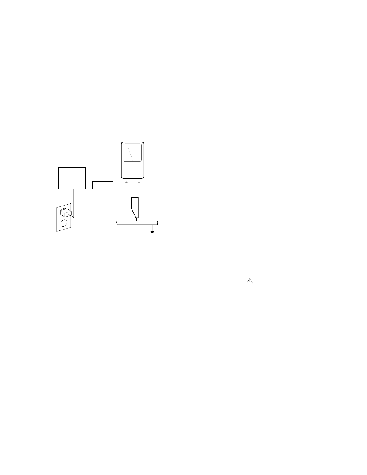
Leakage Current Cold Check
With the AC plug removed from 120V AC 60Hz source,
place a jumper across the two plug prongs. Turn the AC
power switch on. Using an insulation tester (DC 500V), connect one lead to the jumpered AC plug and touch the other
lead to each exposed metal part (input/output terminals,
screwheads, metal overlays, control shafts, etc.), particularly any exposed metal part having a return path to the
chassis. Exposed metal parts having a return path to the
chassis should have a minimum resistor reading of 0.3MΩ
and a maximum resistor reading of 5MΩ. Any resistor value
below or above this range indicates an abnormality which
requires corrective action. Exposed metal parts not having a
return path to the chassis will indicate an open circuit.
2
PRO-700HD
Leakage Current Hot Check
Plug the AC line cord directly into a 120V AC 60Hz outlet (
do not use an isolation transformer for this check). Turn the
AC power switch on.
Using a “Leakage Current Tester (Simpson Model 229
equivalent )”, measure for current from all exposed metal
parts of the cabinet ( input/output terminals, screwheads,
metal overlays, control shaft, etc. ), particularly any exposed
metal part having a return path to the chassis, to a known
earth ground (water pipe, conduit, etc.). Any current measured must not exceed 0.5mA.
Reading should
not be above
0.5 mA
Earth ground
Device
under
test
2-wire cord
Also test with
plug reversed
(Using AC adapter
plug as required)
Test all
exposed metal
surfaces
Leakage
current
tester
AC Leakage Test
ANY MEASUREMENTS NOT WITHIN THE LIMITS OUTLINED
ABOVE ARE INDICATIVE OF A POTENTIAL SHOCK HAZARD
AND MUST BE CORRECTED BEFORE RETURNING THE SET
TO THE CUSTOMER.
High V oltage
This set is provided with a X-ray protection for clearly indicating that voltage has increased in excess of a predetermined value. Comply with all notes described in this Service
Manual regarding this hold down circuit when servicing, so
that this X-ray protection may correctly by operated.
Serviceman W arning
In the status of the black picture ( video muting is being applied ) when no signal is input, high voltage of this set during
operation is less than 30.5kV. In case any component having some relation to the high voltage is replaced, confirm
that the high voltage is lower than 30.5kV in the status of the
black picture when no signal is input.
To measure H.V. use a high impedance H.V. meter.
Connect ( – ) to earth and ( + ) to the FBT anode cable connector.
(Refer to page 214)
X-radiation
TUBE: The primary source of X-radiation in this set is the
picture tube.
For continued X-radiation protection, the replacement tube
must be the same type as the original, PIONEER approved
type.
The picture tube (the CRT assy R, G, B ) use in this set
holds complete guarantee against X-ray radiation when the
X-ray is sealed (See page 4). Accordingly, when the current
in flowing to the picture tube (CRT assy R, G, B) be sure to
perform it by putting the tube into X-ray sealed applied state.
Avoid absolutely to flow the current to the picture tube (CRT
assy R, G, B) itself. Moreover, when the voltage of the high
voltage circuit becomes abnormally a little higher, the picture tube radiates X-rays. Accordingly, when servicing the
high voltage circuit be sure to replace as an assembly with
the DEFLECTION SERVICE assy in the manner in which
has been adjusted to perform normal operation.
1.2 PRODUCT SAFETY NOTICE
Many electrical and mechanical parts in PIONEER set have
special safety related characteristics. These are often not
evident from visual inspection nor the protection afforded by
them necessarily can be obtained by using replacement
components rated for higher voltage, wattage, etc. Replacement parts which have these special safety characteristics
are identified in this Service Manual.
Electrical components having such features are identified
by marking with a
in this Service Manual.
The use of a substitute replacement component which does
not have the same safety characteristics as the PIONEER
recommended replacement one, shown in the parts list in
this Service Manual, may create shock, fire, X-radiation, or
other hazards.
Product Safety is continuously under review and new instructions are issued from time to time. For the latest information, always consult the current PIONEER Service
Manual. A subscription to, or additional copies of PIONEER
Service Manual may be obtained at a nominal charge from
PIONEER.
on the schematics and on the parts list
3
PRO-700HD
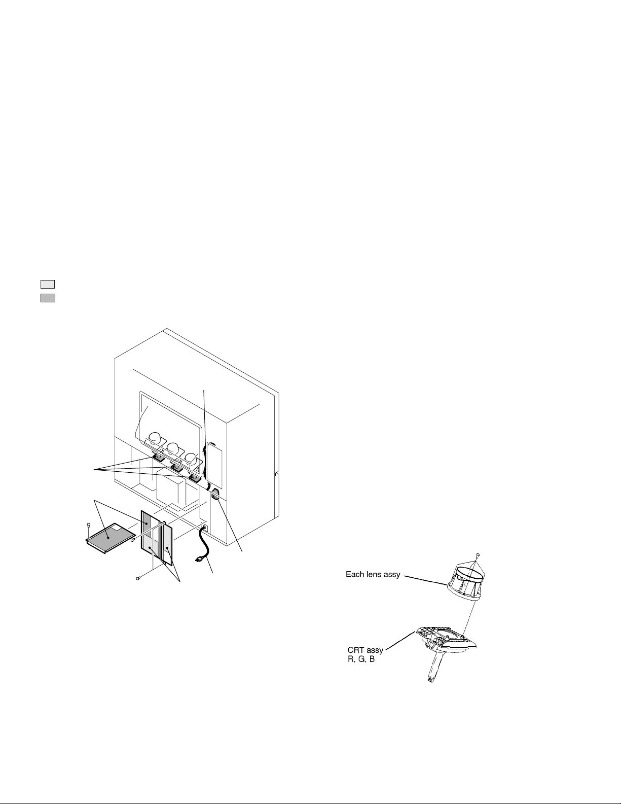
1.3 CHARGED SECTION, HIGH VOLTAGE GENERATING POINT
AND X-RAY PROTECTION
7 Charged section
The circuit in which the commercial AC power is used as it
is without passing through the power supply transformer. If
the charged section is touched, there is a risk of electric
shock. In addition, the measuring equipment can be damaged if it is connected to the GND of the charged section
and the GND of the non-charged section while connecting
the set directly to the commercial AC power supply. In this
case, be sure to connect the set via an insulated transformer
and supply the current.
7 Charged section
(Power supply primary side)
1. The primary side of the AC IN assy
2. AC power cord
3. The primary side of the POWER SUPPLY assy
4. AC power cord for DTV STB
: Part is the charged section.
: Part is the high voltage generating
points other than the charged section.
AC power cord for
DTV STB
High Voltage
generating point
High Voltage
generating point
7 High voltage generating point
The place where voltage is 100V is generated.
1.Charged seciton
DEFLECTION assy
(including FBT) (30.5kV, 1.2kV, 210V,135V)
2. POWER SUPPLY assy (135V)
3. R. CRT DRIVE assy (10.5kV, 210V)
4. G. CRT DRIVE assy (10.5kV, 210V)
5. B. CRT DRIVE assy (10.5kV, 210V)
6. CRT assy R (CRT service assy R) (30.5kV)
7. CRT assy G (CRT service assy G) (30.5kV)
8. CRT assy B (CRT service assy B) (30.5kV)
9. Focus variable resistor(VR1) (10.5kV)
10. Deflection yokes (L1, L2 and L3) Approx. (1100V at peak)
7 X-ray protection
• Regarding the parts which are relative to radiation of Xrays (There is the danger to radiate X-ray from the individual CRT assy R, G, B), there are notifications of caution in the individual schematic diagrams. Be sure to read
them for safety’s sake.
• The component parts for X-ray protection are as follows :
When the current flows to the CRT assy R, G, B, be sure
to perform it with these parts being attached. Protection
from the X-ray radiation is maintained in the state in which
these parts have been installed to the CRT assy. R, G, B.
Accordingly, never supply current only to the CRT assy R,
G, B.
Moreover, the anode voltage of the CRT assy R, G, B
should always be kept not higher than the predetermined
value (in the minimum brightness and picture state when
non signal input is less than 30.5kV). Be sure to drive the
CRT assy R, G, B by using a completely functional DEFLECTION assy which have been adjusted completely in
the combined state. (When the voltage abnormally becomes high, the X-ray protection circuit will operate.)
1.CRT assy R, G, B (Do not dismantle CRT assemblies un-
der any circumastances)
2.Each Lens assy
High Voltage
generating point
AC Power cord
Charged section
Fig. 1 Charged section and high voltage generating point
4
Fig. 2 Component parts for X-ray protection
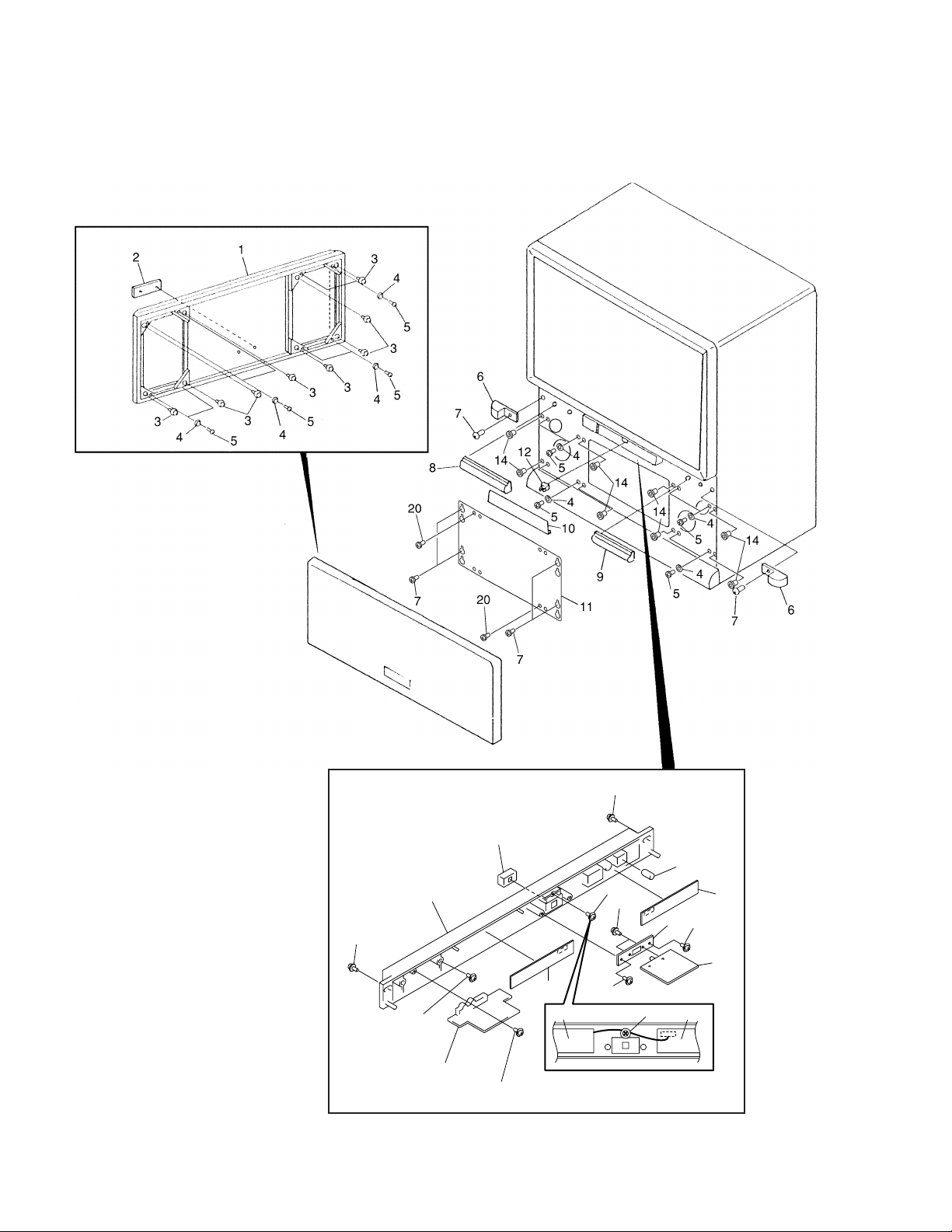
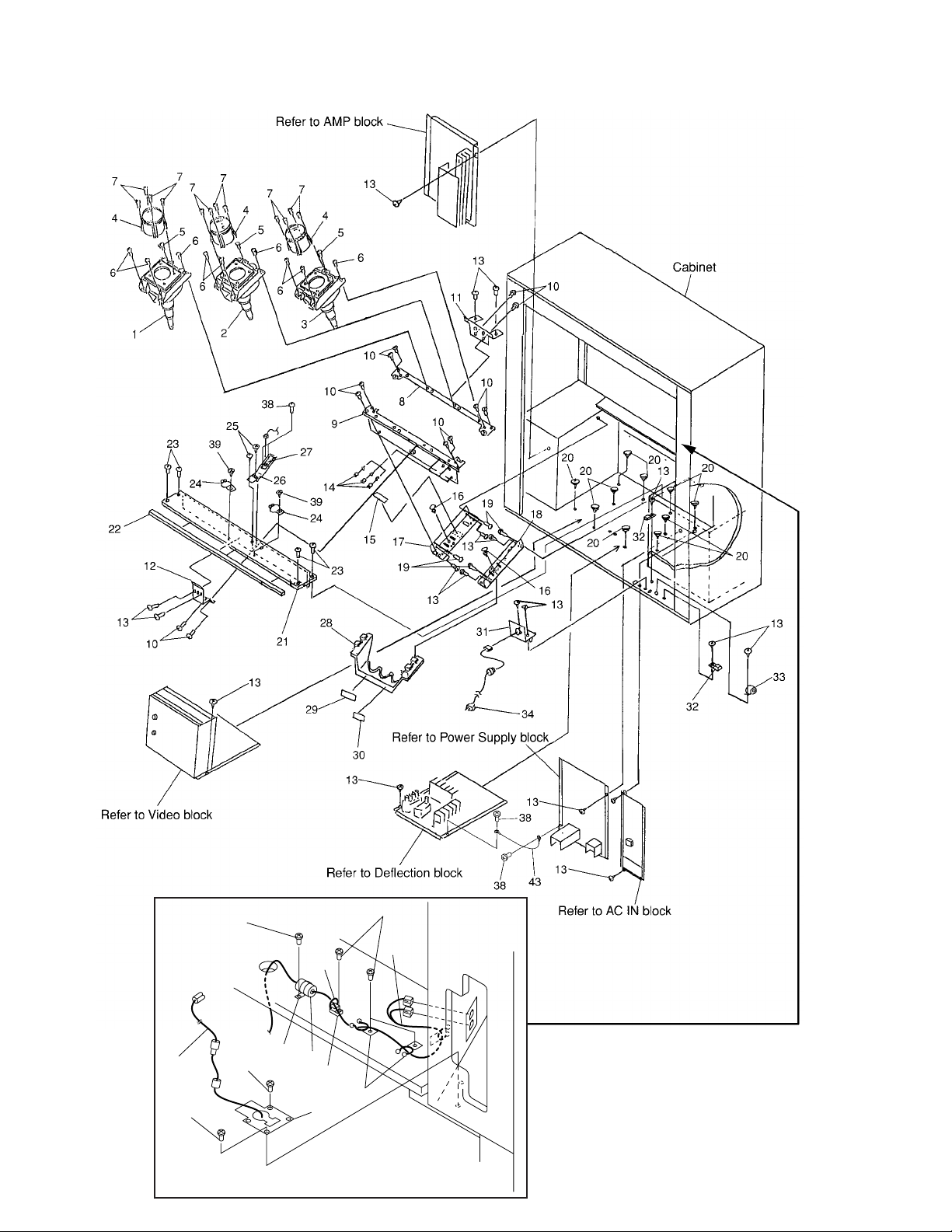
2. EXPLODED VIEWS AND PARTS LIST
NOTES:•Parts marked by "NSP" are generally unavailable because they are not in our Master Spare Parts List.
The mark found on some component parts indicates the importance of the safety factor of the part.
•
Therefore, when replacing, be sure to use parts of identical designation.
Parts marked by are important parts which relate in X-rays radiation.
•
If any of these parts need to be replaced, always replace with specified parts.
Screws adjacent to mark on the product are used for disassembly.
•
PRO-700HD
2.1 PACKING
• PACKING PARTS LIST
Mark No. Description Part No.
1 Upper Carton 64W AHD2994
2 Under Carton 64W AHD2995
3 Upper Pad L AHA2222
4 Upper Pad R AHA2223
5 Under Pad L AHA2224
6 Under Pad R AHA2225
NSP 7 Vinyl Sheet 64W Upper AHG1288
NSP 8 Packing Sheet 60 AHG1230
NSP 9 Packing Sheet 64 Under AHG1290
10 Vinyl Sheet 64W Under AHG1289
11 Remote Control Unit AXD1438
(CU-SD105)
12 Battery Cover AZN2401
NSP 13 Alkarine Dry Cell Battery AEX1018
(LR6,AA)
14 CU Packing Case AHC1032
15 Special Screw ABA1239
16 CONV. Attention Card ARM1151
17 Operating Instructions ARB1519
(English)
NSP 18 Caution Card ARM1057
NSP 19 Warranty Card EL ARY1026
NSP 20 Poly Bag AHG1285
21 ...........
22 Special Screw ABA1226
(Panel Frame Attaching Screw)
NSP 23 Wrapper Bag AHG1076
NSP 24 Literature Bag AHG1222
25 Panel Case 64W AHB1202
NSP 26 Vinyl Sheet 64W (for Panel) AHG1286
27 Protective Screen AAK2729
28 Acrylic Caution Card ARH1160
29 Frame Cover H AAP1593
30 Frame Cover V AAP1594
31 Panel Frame H AND1163
32 Panel Frame V AND1164
NSP 33 Under Cushion A AHA2228
NSP 34 Under Cushion B AHA2229
Note : As for accessory parts of part No. 22, 27 and 29 to 32, refer
to page 7.
5
PRO-700HD
2.2 FRONT VIEW (1/2)
7
15
26
13
7
19
16
17
16
22
23
21
24
25
24
18
2519 22
6
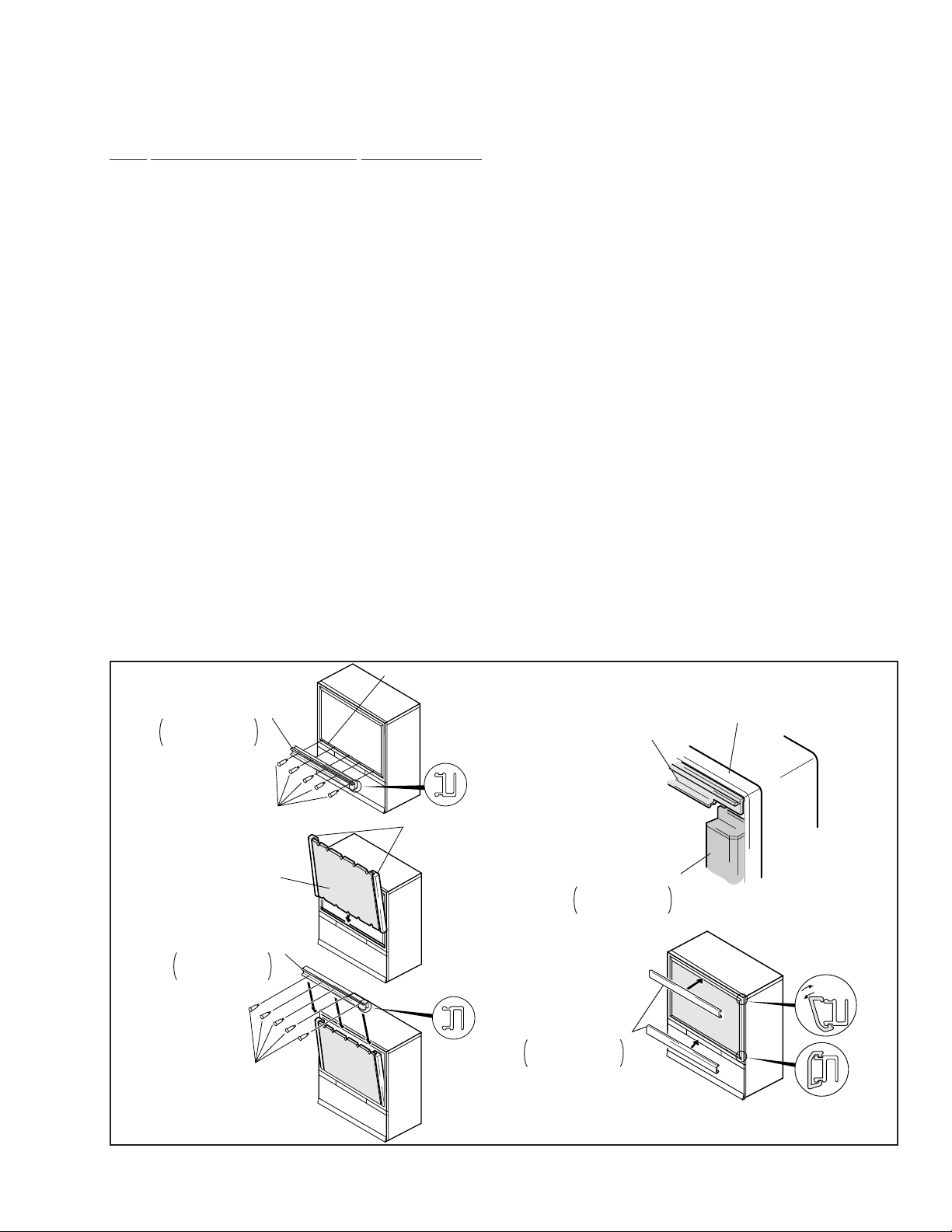
(1) FRONT VIEW (1/2) PARTS LIST
Mark No. Description Part No.
1 Grille 64 AMM2936
2 Badge AAM1081
NSP 3 Catcher A ANZ-241
4 Magic Tape AEC1394
5 Screw ABA1271
6 Side Cover AMR3107
7 Special Screw ABA1240
8 Side Panel Assy L (64W) AMB2627
9 Side Panel Assy R (64W) AMB2635
10 Door Assy AAN1444
11 Blind Plate AMM2933
12 Cather F2M AEC1609
13 Front Panel Assy AMB2625
14 Catch B ANZ-242
15 Power Knob AAD4102
16 Screw ABZ40P080FZK
17 FRONT INPUT Assy AWZ6339
18 POWER SW Assy AWZ6341
19 FRONT CONTROL Assy AWZ6337
20 Screw ABA1239
PRO-700HD
NSP 21 Switch Holder ANG2313
22 Screw ABA1269
23 Screw AMZ30P060FZK
24 Screw APZ30P080FZK
25 LED DPO Assy AWZ6338
26 LED Lens AAK2730
• Accessory Parts
Panel frame
31 Panel Frame H
AND1163
22 Panel Frame Attaching Screw
(ABA1226)
27 Protective screen
(AAK2729)
Panel frame
31 Panel Frame H
AND1163
Screen frame
Side view
32 Panel Frame V
(AND1164)
Upper panel frame
Side frame cover
30 Frame Cover V
AAP1594
Screen frame
Upper frame cover
Remove
Attach
22 Panel Frame Attaching Screw
(ABA1226)
Side view
Frame Cover
29 Frame Cover H
AAP1593
Lower frame cover
7
PRO-700HD
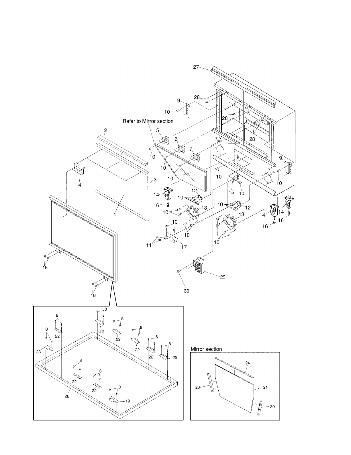
2.3 FRONT VIEW (2/2)
8

(1) FRONT VIEW (2/2) PARTS LIST
Mark No. Description Part No.
1 Lenticular Sheet AMR3115
2 Screen Holder Top 64 ANG2312
3 Fresnel 64W AMR3116
NSP 4 Upper Cabinet Metal ANG2000
NSP 5 Mirror Upper Stay L ANG2004
NSP 6 Mirror Upper Stay C ANG2006
NSP 7 Mirror Upper Stay R ANG2005
NSP 8 Screw BYC35P160FMC
NSP 9 Screen Side Fitting ANG1993
10 Special Screw ABA1240
11 Screw ACZ40P080FMC
12 Speaker 66 (Tweeter) D66AP45-56L
13 Cone Speaker APV1048
14 Caster AMR2547
NSP 15 VR Holder ANG1956
16 Special Screw SBA-140
NSP 17 CRT Front Holder ANG2118
18 Screw M5 ABA1189
NSP 19 Under Screen Metal B ANG2009
20 Mirror Frame V 64W ANG2315
PRO-700HD
21 Mirror 64 AMR3113
NSP 22 Upper Screen Metal B ANG2002
NSP 23 Under Screen Metal A ANG2003
24 Mirror Frame H 64 W ANG2314
NSP 25 Upper Screen Metal A ANG2001
26 Screen Frame Assy 64W AAP1592
27 Screen Holder Low 64W AAP1601
28 Screw BYC35P160FZK
29 Focus VR (VR1) ACX1096
30 Screw BBZ30P080FZK
9
PRO-700HD
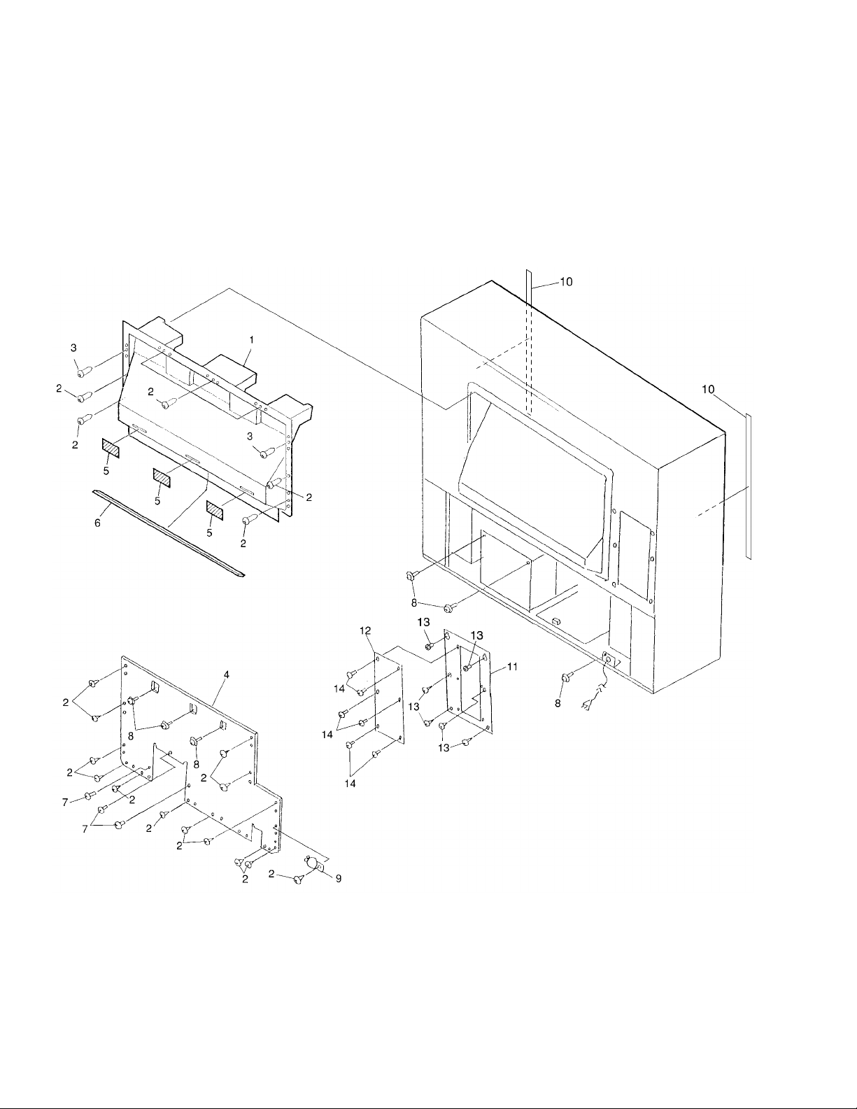
2.4 REAR VIEW (1/2)
10

(1) REAR VIEW (1/2) PARTS LIST
Mark No. Description Part No.
1 Mirror Case 51 AME2296
2 Screw ABA1240
3 Screw PYC40T140FZB
4 Rear Cover AMM2929
5 Blind Sheet AEC1622
6 Mirror Case Coshion AEC1627
7 Screw ABZ30P100FZK
8 Screw ABA1269
NSP 9 Cabinet Wire Holder AEC1263
10 Screen Cushion 64 AEC1778
11 Rear Cover (DTV) Assy ANE1577
12 Rear Cover Sheet AMR3135
13 Screw PMB40P160FZB
14 Screw BCZ30P080FZK
15
PRO-700HD
11
PRO-700HD
2.5 REAR VIEW (2/2)
12
37
44
13
44
41
39
36
42
40
32
24
35

(1) REAR VIEW (2/2) PARTS LIST
Mark No. Description Part No.
1 CRT Service Assy 64B AWY1415
2 CRT Service Assy G AWY1413
3 CRT Service Assy 64R AWY1414
4 Lens Assy AMR3121
5 Screw FBT40P120FZK
6 Screw ABA1168
7 Screw AMZ40P080FZK
NSP 8 CRT Front Frame ANA1541
NSP 9 CRT Rear Frame ANA1542
10 Screw ACZ40P080FMC
NSP 11 CRT Front Holder ANG2118
NSP 12 CRT Rear Holder ANG2119
13 Screw ABA1240
14 Cord Holder AEC1257
NSP 15 Tube Label AAX2497
16 Rivet AEC-441
NSP 17 CRT Stand Holder R ANA1497
NSP 18 CRT Stand Holder L ANA1496
19 Screw PMB50P250FZB
20 Special Screw ABA1121
PRO-700HD
Mark No. Description Part No.
OTHERS
1P Lead Wire (J3) ADX2231
1P Lead Wire (J4) ADX2232
1P Lead Wire (J5) ADX2233
1P Lead Wire (J6) ADX2289
1P Lead Wire (J7) ADX2290
1P Lead Wire (J8) ADX2291
4P Housing Wire (J2) ADX2484
Wire Harness A (J10) ADX2485
Wire Harness B (J11) ADX2487
NSP 21 Back Cover Panel AMM2939
22 Back Cover Cushion AEC1779
23 Screw ABA1241
NSP 24 Cabinet Wire Holder AEC1263
25 Screw ABA1210
NSP 26 Fixing Metal ANG1958
27 SR Assy AWZ6340
NSP 28 Tray AMR2563
NSP 29 Solder Warning Label AAX2672
NSP 30 Warning Label (KC) AAX1797
NSP 31 AC Cord Holder A ANG2307
NSP 32 Bind Holder AEC1785
33 Ferrite Core ATX1033
34 AC Power Cord ADG1180
NSP 35 AC Cord Holder B ANG2311
36 Wire Harness C (J14) ADX2491
37 AC Power Cord B ADG1181
38 Screw BBZ30P080FZK
39 Screw ABA1271
40 Ferrite Core ATX1031
NSP 41 Nylon Clamp 18N AEC1789
42 Nylon Binder AEC-093
43 1P Lead Wire (J1) ADX2505
44 Screw PMB40P250FZB
13
PRO-700HD
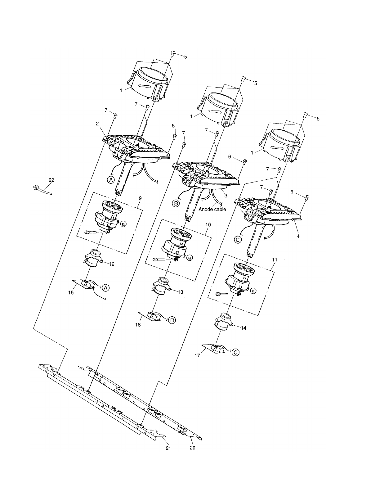
2.6 CRT BLOCK
14

(1) CRT BLOCK PARTS LIST
Mark No. Description Part No.
1 Lens Assy AMR3121
2 CRT Service Assy 64R AWY1414
3 CRT Service Assy G AWY1413
4 CRT Service Assy 64B AWY1415
5 Screw AMZ40P080FZK
6 Screw FBT40P120FZK
7 Screw ABA1168
8 ...........
9 Deflection Yoke (L1) ATL1136
10 Deflection Yoke (L2) ATL1136
11 Deflection Yoke (L3) ATL1136
12 VM Coil (L4) ATL1137
13 VM Coil (L5) ATL1137
14 VM Coil (L6) ATL1137
15 R.CRT DRIVE Assy AWZ6344
16 G. CRT DRIVE Assy AWZ6345
17 B. CRT DRIVE Assy AWZ6346
18 ............
19 ............
NSP 20 CRT Rear Frame 62 ANA1542
PRO-700HD
NSP 21 CRT Front Frame 62 ANA1541
22 Nylon Binder AEC-093
15
PRO-700HD
2.7 VIDEO BLOCK
Refer to
“2.8 SIGNAL ASSY BLOCK”
Refer to
“2.8 SIGNAL ASSY BLOCK”
Refer to
“2.8 SIGNAL ASSY BLOCK”
(1) VIDEO BLOCK PARTS LIST
Mark No. Description Part No. Mark No. Description Part No.
NSP 1 Video Chassis ANA1584
2 VIDEO Assy AWV1716
3 AV / IO Assy AWV1714
4 Rear Panel ANC2321
5 ...........
6 ...........
7 Nut ABN-087
8 Screw BBZ30P080FZK
9 Screw BBZ30P080FCU
10 TUNER u-COM Assy AWV1715
16
11 SIGNAL Assy AWV1717
12 SUB VIDEO Assy AWV1718
13 RF Switch AXF1098
14 Washer WAXOF160N100
NSP 15 Lead Clamper M AEC1611
NSP 16 Cable Clip AEP-214
NSP 17 PCB Side Holder ANG2305
18 SR BNC Assy AWZ6342
19 Screw BCZ30P080FZK
20 4P Housing Wire (J13) ADX2490
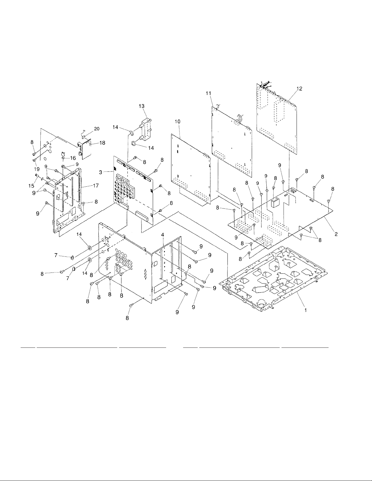
2.8 SIGNAL ASSY BLOCK
PRO-700HD
(1) SIGNAL ASSY BLOCK PARTS LIST
Mark No. Description Part No.
1 Shield Cover ANK1562
NSP 2 PCB Sub-Frame ANG2304
NSP 3 Lead Clamper M AEC1611
4 SUB VIDEO Assy AWV1718
5 Screw BBZ30P080FCU
NSP 6 Analog Shield B ANK1537
7 SIGNAL Assy AWV1717
8 TUNER u-COM Assy AWV1715
NSP 9 Cable Clip D3M AEC1783
10 Screw ABZ30P080FCU
Mark No. Description Part No.
11 Shield Front Cover B ANK1592
12 Shield Rear Cover B ANK1596
13 Shield Front Cover A ANK1591
17
PRO-700HD
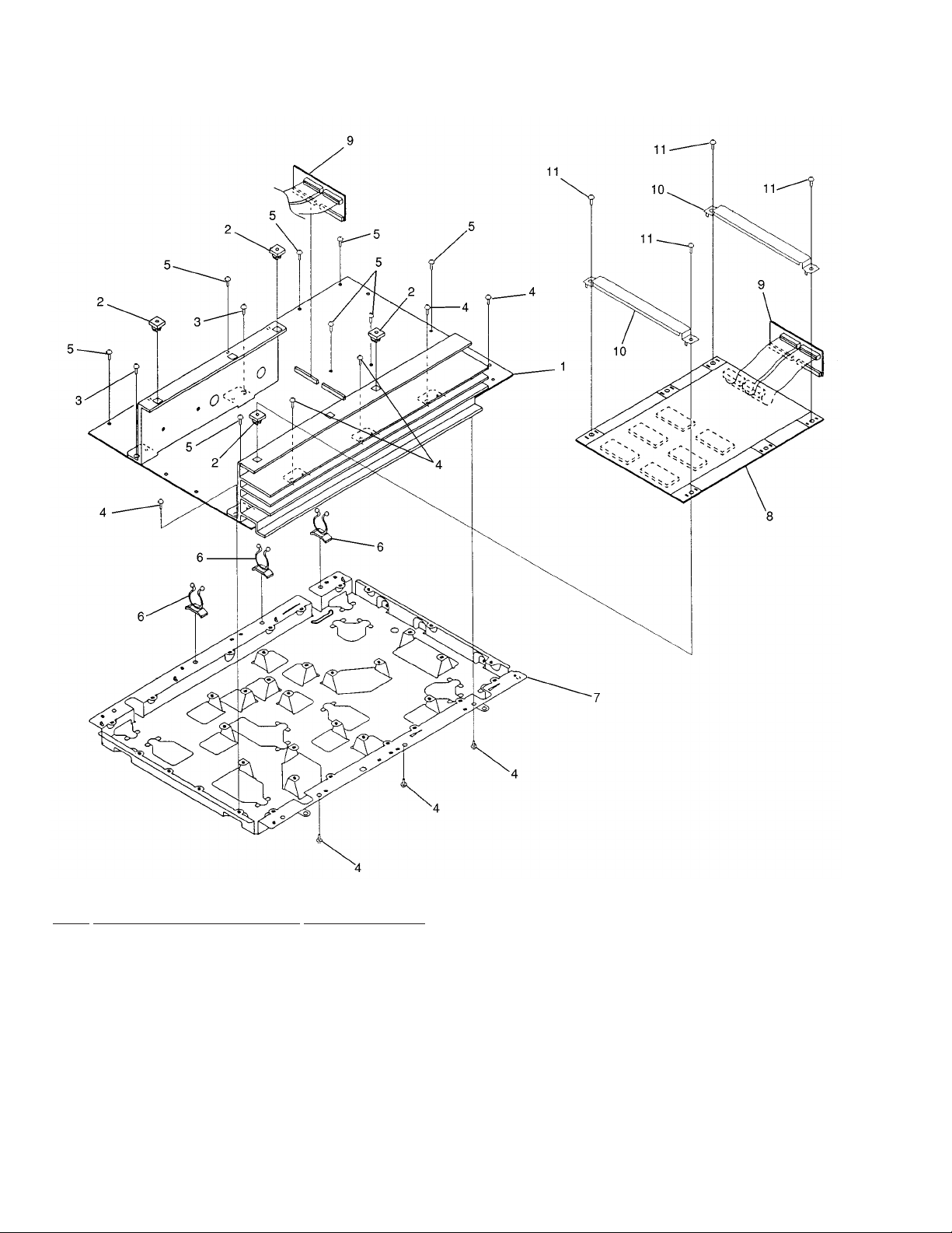
2.9 AMP BLOCK
(1) AMP BLOCK PARTS LIST
Mark No. Description Part No.
1 AMP Assy AWV1712
2 Grommet AEC1418
3 Special Screw ABA1099
4 Screw ABZ30P100FZK
5 Screw BBZ30P080FZK
NSP 6 Cable Clip D3M AEC1783
NSP 7 AMP Chassis ANA1585
NSP 10 Head Sink Holder ANG2306
18
8 CONVER . DAC Assy AWZ6333
9 CONNECTOR Assy AWZ6335
11 Screw VPZ40P120FZK
12
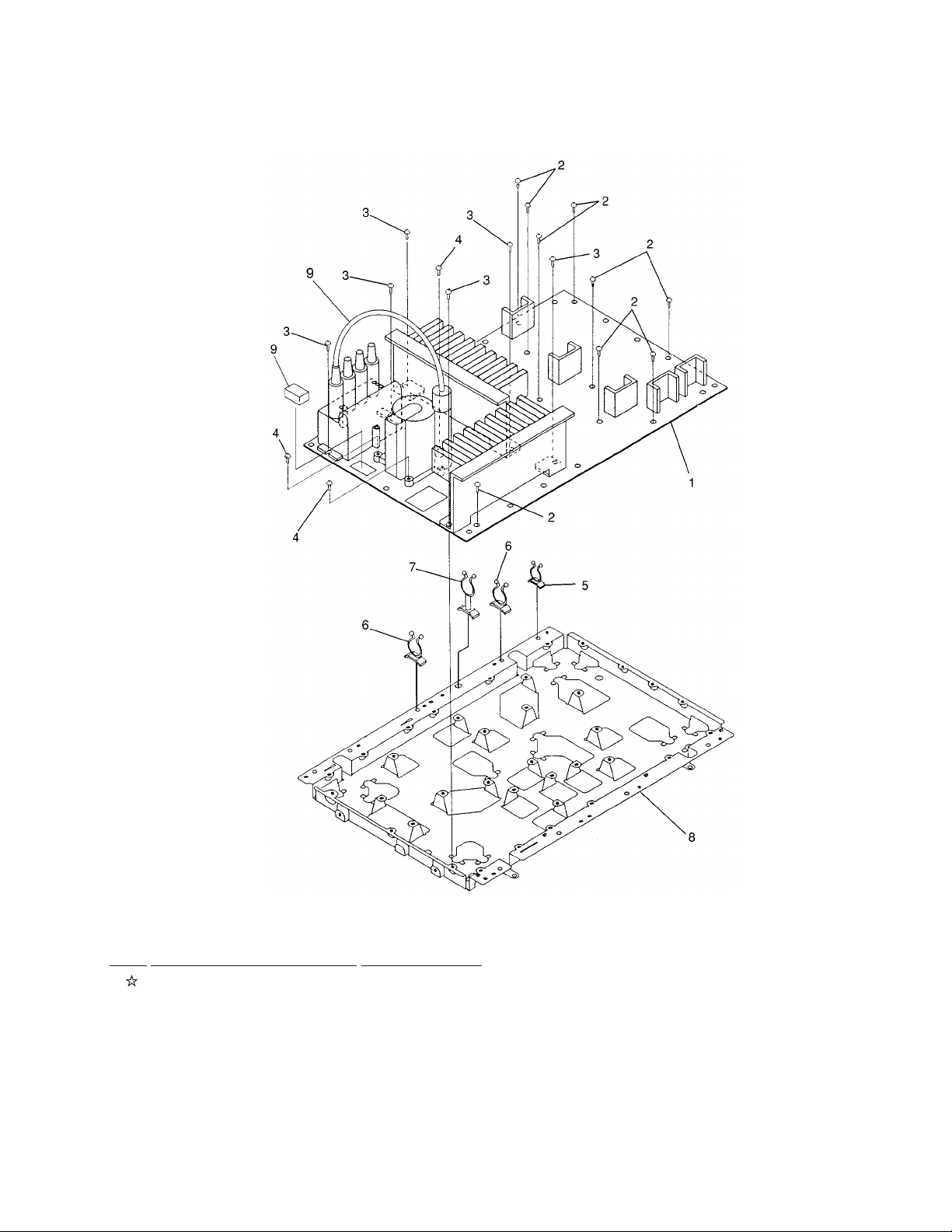
2.10 DEFLECTION BLOCK
PRO-700HD
(1) DEFLECTION BLOCK PARTS LIST
Mark No. Description Part No.
1 DEFLECTION SERVICE AWV1731
Assy
2 Screw BBZ30P080FZK
3 Screw ABZ30P100FZK
4 Screw VBZ30P200FMC
NSP 5 Cable Clip D3S AEC1782
NSP 6 Cable Clip D3M AEC1783
NSP 7 Cable CliP AEC1325
NSP 8 DF Chassis ANA1583
9 Shield Case ANK1510
19
PRO-700HD
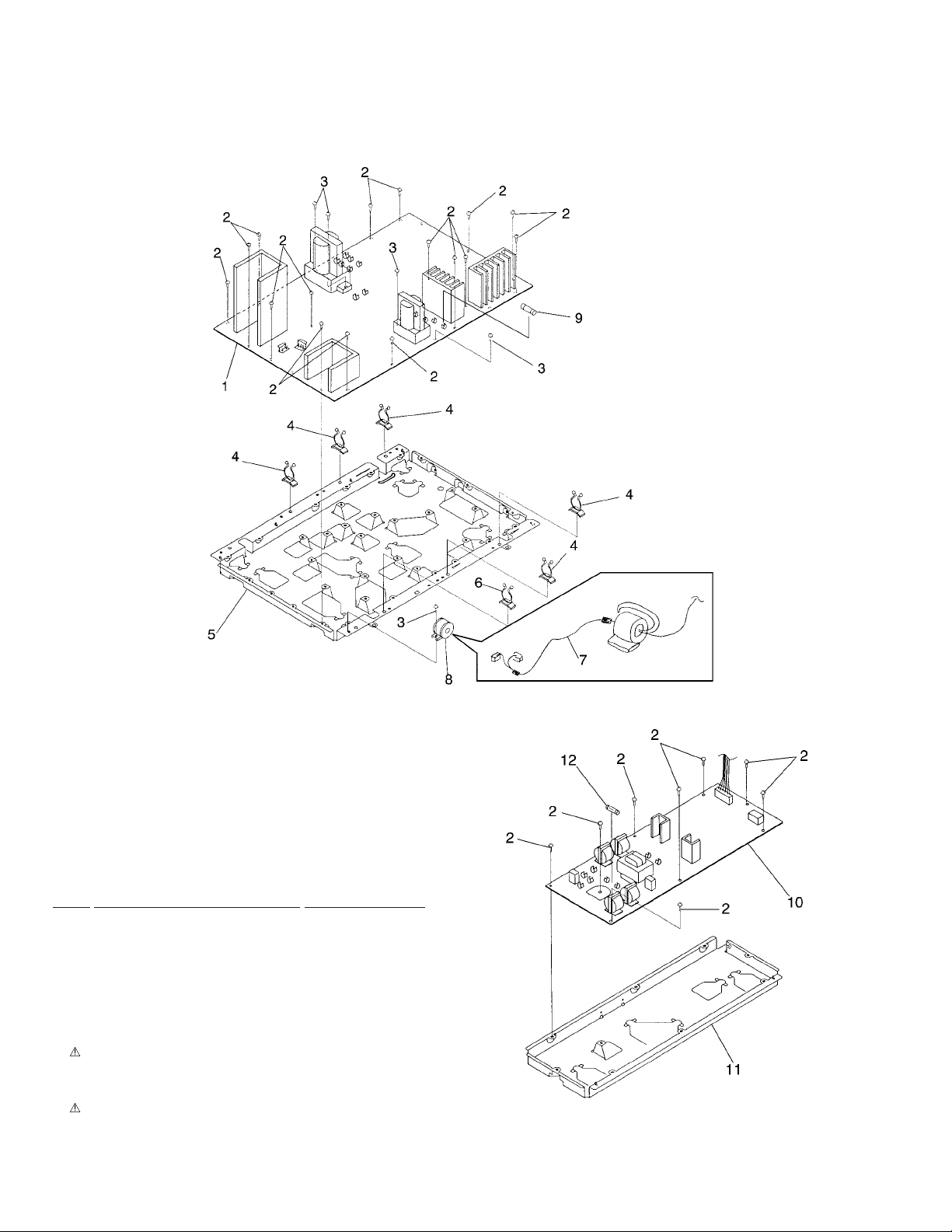
2.11 POWER SUPPLY / AC IN BLOCK
Power Supply Bkock
AC IN Block
(1) POWER SUPPLY / AC IN BLOCK PARTS LIST
Mark No. Description Part No.
1 POWER SUPPLY Assy AWV1710
2 Screw BBZ30P080FZK
NSP 4 Cable Clip D3S AEC1782
NSP 5 PS Chassis ANA1582
NSP 6 Cable Clip D3M AEC1783
NSP 11 LF Chassis ANA1586
3 Screw ABZ30P100FZK
7 Wire Harness D (J15) ADX2489
8 Ferrite Core ATX1033
9 Fuse (6.3A/125V) REK1085
10 AC IN Assy AWZ6353
12 Fuse (500mA/125V) AEK1010
20

PRO-700HD
21
1234
1
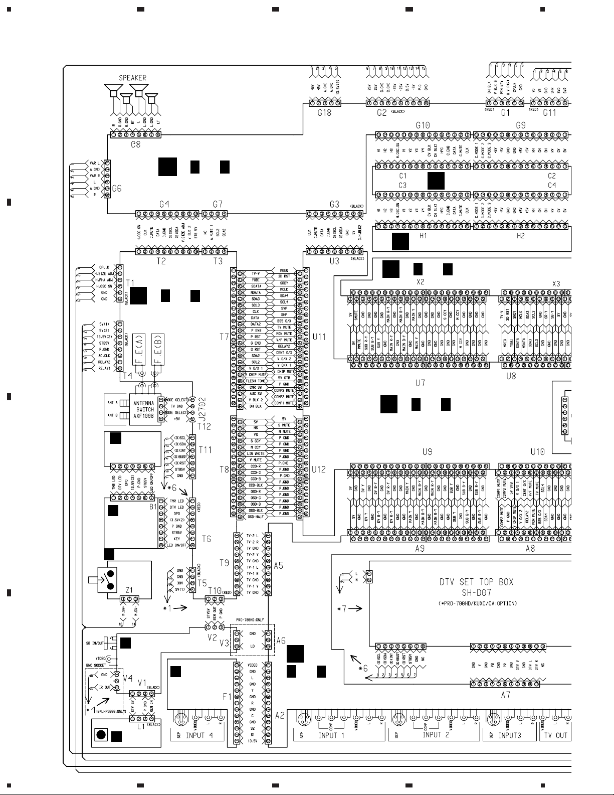
PRO-700HD
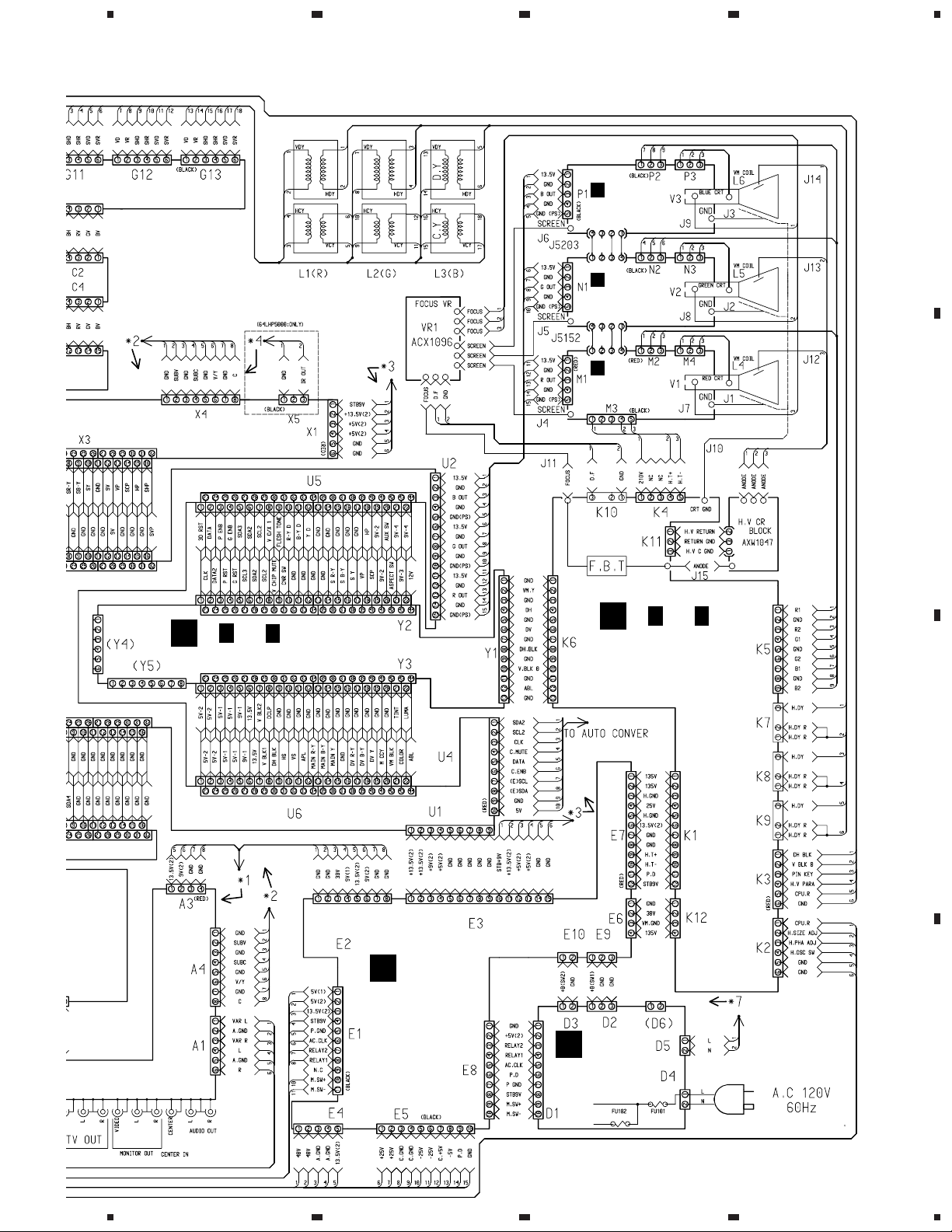
3. SCHEMATIC DIAGRAM 3.1. OVERALL CONNECTION DIAGRAM
A
1/3E3/3
( - )
E
AMP ASSY (AWV1712)
E
CONNECTOR ASSY
G
(AWZ6335)
CONVER.DAC ASSY (AWZ6333)
F
1/8D 8/8D
( - )
D
1/3A 3/3A
( - )
B
C
A
TUNER u-COM ASSY
(AWV1715)
K
LED DPO ASSY
(AWZ6338)
1/2B 2/2B
( - )
B
VIDEO ASSY
(AWV1716)
SIGNAL ASSY (AWV
J
FRONT
CONTROL ASSY
(AWZ6337)
POWER SW ASSY
L
(AWZ6341)
SR BNC ASSY
H
(AWZ6342)
N
FRONT INPUT
I
ASSY
D
Not Used
SR ASSY
M
(AWZ6340)
22
1234
(AWZ6339)
1/3N 3/3N
( - )
AV I/O ASSY
(AWV1714)
5678
3
PRO-700HD
A
R
B CRT DRIVE ASSY
(AWZ6346)
Q
G CRT DRIVE ASSY
Not Used
(AWZ6345)
33)
AWV1717)
( - )
C
1/5C 5/5C
SUB VIDEO ASSY (AWV1718)
P
R CRT DRIVE ASSY
(AWZ6344)
1/3S 3/3S
( - )
S
DEFLECTION
SERVICE ASSY
B
(AWV1731)
C
T
POWER
SUPPLY ASSY
(AWV1710)
O
AC IN ASSY
(AWZ6353)
4A 125V
56
7
D
10A 250V
23
8
1234
7
P
N
PRO-700HD
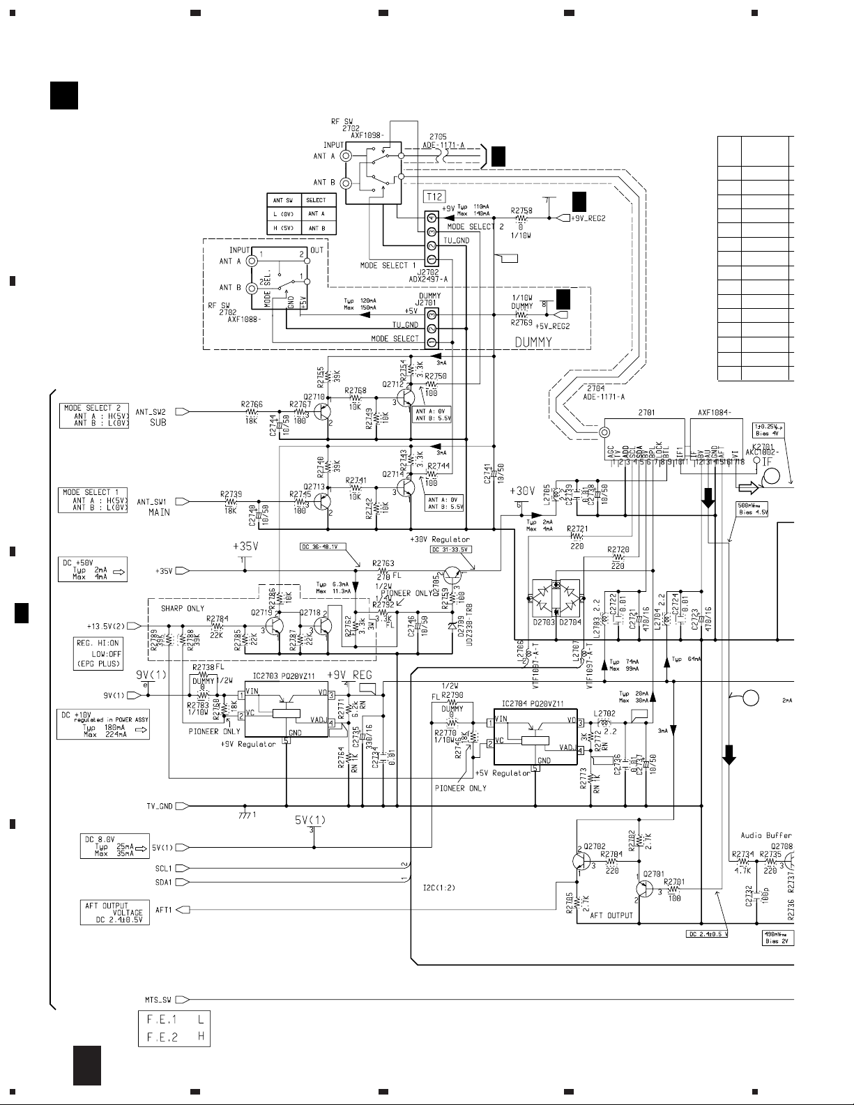
3.2 TUNER u-COM ASSY (1/3)
TUNER u-COM ASSY (1/3) (AWV1715)
A
• TUNER 1 BLOCK
A
B
A
2/3
9.0
Not used
A
A
2/3
2/3
IC2701 (CXA1
Pin
Voltage
No.
[V]
1
–
2
–
3
0
4
0
5
1.3
6
1.3
7
3.9
8
3.9
9
3.3
10
3.6
11
4.0
12
1.3
13
3.6
14
3.6
15
9.0
(C)
Not used
3/3
A
C
9.0
5.0
1.25
1.25
1
3
(C)
D
24
A 1/3
1234
5678
PRO-700HD
(CXA1734S)
Pin
oltage
No.
[V]
–
16
–
17
0
18
0
19
1.3
20
1.3
21
3.9
22
3.9
23
3.3
24
3.6
25
4.0
26
1.3
27
3.6
28
3.6
29
9.0
30
1
Voltage
[V]
2.9
0
3.6
3.6
3.5
4.0
1.7
4.0
3.9
3.9
1.8
1.3
4.0
4.0
–
FRONT END
M2701 (M2801)
Pin
Voltage
No.
[V]
7.0
1
1.0
2
0*
3
–
4
–
5
9.0
6
5.0
7
–
8
33
9
*M2801 [5V]
Pin
No.
10
11
12
13
14
15
16
17
18
Voltage
[V]
–
–
–
9.0
4.7
0
3.0
–
4.7
SIGNAL ROUTE
: Video Signal Route (TV1,TV2)
: Audio Signal Route (TV1.L,TV2.L)
(C)
: Composite Audio Signal Route
A
A
B
3/3
4
2
2.0
2.0
2.0
(C)
3.4
3.4
(TV1)
4.3‘6.3
IC2701:
MTS DECODER
9.0
1/3
N
CN6002
A5
(TV2)
(C)
A
2/3
C
D
56
A 1/3
7
8
25
1234
PRO-700HD
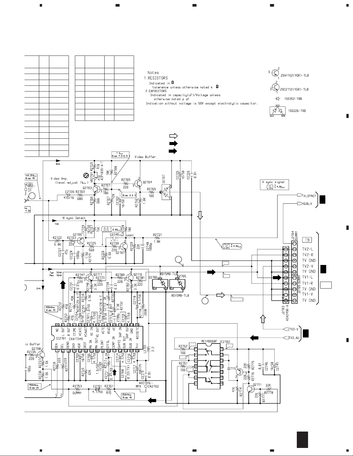
3.3 TUNER u-COM ASSY (2/3)
A
TUNER u-COM ASSY(2/3) (AWV1715)
A
• TUNER 2 BLOCK
3/3
A
B
A
1/3
33
1/3
A
3/3
A
1/3
A
5
3/3
A
4. 7
C
1/3
A
1.25
(C)
(TV2)
5
9
1.25
D
26
A 2/3
1234
5678
PRO-700HD
A
3/3
A
(TV2)
(C)
(TV2)
(TV2)
B
4.5
2
(C)
SIGNAL ROUTE
(TV2)
: Video Signal Route (TV2)
(C)
: Composite Audio Signal Route
C
56
D
A 2/3
7
8
27
1234
2
PRO-700HD
3.4 TUNER u-COM ASSY (3/3)
A-a
3/3
A
J5024
H
J
CN5001
V2
TUNER u-COM ASSY (3/3) (AWV1715)
A
• µ-COM BLOCK
5
0
5
0
9.1
0
0
7.5
1.25
5
0.7
0.1
4.7/50
C2207
0.1
2.8
R2233
0
15K
0.1
B1
0
DTV SET
TOP BOX
SH-DO7
CN209
T
B
A
1/3
A
1/3,2/3
A
A
2/3
2/3
A
A
A
A
E2
1/3
A
2/3
1/3
2/3
TV_GND
+13.5V(2)
1/3
H_SYNC1
H_SYNC2
MTS_SW1
ANT_SW1
ANT_SW2
5V(1)
9V(1)
35V
SCL5
SAA5
AFT1
AFT2
SCL1
SDA1
SUB_V
TV_V
IC2207:
RESET
5
5
D2331
0
0
D2215
CN210
T
EI
2827
C
2/2
E
CN1205
0
D2255
D2241
G7
1/2
E
CN908
G4
0
1/3
S
CN308
K2
D
0.6
28
A 3/3
13. 5
10. 4
1234
9. 8
C2264
1.0/50
0
4. 3
5
R2446
100
5
0
0. 1
5
0. 7
2. 8
0
5
0. 7
2. 8
0
5
5
0
5
R2412
100
0
0
0. 7
0
2. 8
5
5
0
0
0. 7
0
5
5678
A-b
3.9
0
8. 1
3/3
5
1. 25
A-aA-a A-b A-b
R2382
D2274
PRO-700HD
Large size
SCH diagram
A-aA-a
A-a A-a
A-b A-b
A-b A-b
Guide page
Detailed page
A
CN5605
2/2
B
D2336D2334
C2216
100/10
10K
IC2205:
RESET
0
0
U11
B
5
5
Not use
100
R2347
10K
R2486
100
R2358
5
0
5
5
R2335
100
4. 3
5
0
0. 2
4. 7
4. 7
0. 2
0
0
0
5
0
0
0
1.1
D2238
1K
0.2
R2364
5
0.5
D2262
5
5
0.6
2.7K
15K
R2260
0
0
0
C2237
CH
39p
1.0K
R2263
C2225
0.01
470
R2261
D2207
0
R2573
Q2227
R2564
100
470
R2563
Q2226
R2562
100
470
R2561
5
0
0
0
0
2/2
CN5604
B
U12
C
Q2228
R2536
R2566
3.3K
100
470
R2565
Q2229
R2568
100
2.2K
R2567
5
0
0
0
0
0
0
0
0
D
SIGNAL ROUTE
0. 7
2. 8
1. 7
5
0. 6
0
Note: As for voltages of IC2201, IC2202 and IC2203
refer to page 108.
56
: Video Signal Route
7
A 3/3
8
29
PRO-700HD
T
CN210
A
1234
3/3
2.8
0
15K
R2233
D2215
A-b
0.1
0.1
A-a
1.25
7.5
0.1
4.7/50
C2207
0
D2331
0
RESET
IC2207:
0
5
0
5
3/3
B
9.1
0.7
5
0
0
5
0
C
TUNER u-COM ASSY (3/3) (AWV1715)
• µ-COM BLOCK
5
A
35V
5V(1)
9V(1)
TV_GND
D
V2
B1
E2
1/3,2/3
A
SH-DO7
TOP BOX
CN209
T
30
A-a
J5024
H
CN5001
J
DTV SET
3/3
1234
SCL5
SAA5
+13.5V(2)
1/3
A
2/3
A
AFT1
AFT2
1/3
A
2/3
A
H_SYNC1
H_SYNC2
MTS_SW1
2/3
A
1/3
A
SCL1
SDA1
ANT_SW1
SUB_V
ANT_SW2
1/3
A
TV_V
2/3
A
 Loading...