

Pioneer PRO-620HD User Manual

HDTV PROJECTION MONITOR
PRO-720HD
PRO-620HD
PRO-520HD
Operating Instructions

FEA TURES
Progressive Scan/HDTV READY
All SDTV and HDTV signals are converted to 1080i signals and
displayed at high resolution.
Dual System Component Input for NTSC/
Progressive
Connection to a DVD player with a component output terminal
makes possible high picture-quality display, superior to that
of S-VIDEO terminal connection. Also handles high resolution
component input (1080i, 480p), which will function as an
interface for high-quality images in future.
DUAL TUNER (SPLIT screen and SEARCH
screen function)
Two TV tuners are provided, making it possible to split the
screen vertically in two and display moving images
simultaneously on them. In addition, the channel search
function makes it possible to check, etc., on the program in the
back. This adds remarkable convenience when you are
concerned with two programs.
Fully Illuminated Remote Control Unit
A fully illuminated universal remote control is used that makes
it possible to operate other devices. Remote operations can
thus be performed easily even in dark rooms and similar
environments.
Highly Detailed Image Display T echnology
The 0.52mm ultrafine-pitch screen, Hi Band Video Amplifier
circuit, Progressive contour correction circuit and various other
technologies for creating high picture quality make the display
of highly detailed images possible.
Lens System for HDTV
Adoption of a lens system for high-resolution HDTV that
faithfully reproduces HDTV 1080i signals allows highly colorsaturated images to be displayed at high resolution.
Whole Screen IR Receiver
The remote control sensor is installed behind the screen,
allowing you to operate this monitor with the remote control
unit in those installations where only the screen is revealed.
3D Y/C Separation Circuit
This three-dimensional Y/C separation circuit reproduces
clearer picture quality.
Scan V elocity Modulation Circuit
Precise images from progressive scanning can be displayed
in even greater detail, owing to the Scan V elocity Modulation
(SVM) circuit. In accordance with image type and preference,
the level of effect can be changed in terms of three stages.
T inted Protective Screen
The accompanying protective screen is tinted, not only to
protect the screen but to present more natural high-contrast
images by renewing the color.
Pioneer's PureCinema Format Converter
An advanced and exclusive I/P (Interlace/Progressive) format
converter developed by Pioneer , called “PureCinema”, delivers
a high-resolution progressive picture. It reproduces film
material in a very smooth and film-like image. This is perfect
technology for movie lovers.
Reference Theater Mode
This mode reproduces film material just like a real film image.
By cutting video enhancement circuits, the picture becomes
more natural and looks filmlike.
Room Light Sensor (RLS)
When you select RLS on (LEVEL 1, LEVEL 2), in accordance
with the ambient light of your room, TV automatically adjusts
the picture brightness to reduce eye strain.
Multi-Point Convergence System
Thanks to new convergence system digital technology, not
only can the center of the screen be adjusted, so can an amazing
72 other points (full mode) across the viewing area. This makes
it possible to display clear images with no color distortion
around the entire screen.
The adjustment is easily done using the remote control.
Program Block (V . CHIP)
You can block selected programs based on the established
rating system for television and movies.
<U.S.A. RA TING SYSTEM>
The TV Parental Guidelines are used to rate television
programming: <TV-Y>, <TV-Y7>, <TV-G>, <TV-PG>, <TV-14>
and <TV-MA>.
The Motion Picture Association of America (MP AA) guidelines
are used to rate movies: <G>, <PG>, <PG-13>, <R>, <NC-17>,
<X> and <NR>.
<CANADIAN RA TING SYSTEM>
The Canadian English Language Rating system is used to rote
television programming: <C>, <C8+>, <G>, <PG>, <14+> and
<18+>.
The Canadian French Language Rating system is used to rate
television programming: <G>, <8+>, <13+>, <16+> and <18+>.
In order to block programming you feel is inappropriate, rating
limits can be set on both systems using the remote control
and a password.
Read and understand these 'Operating
Instructions' before operating your Monitor .
Follow the 'IMPORTANT SAFETY
INSTRUCTIONS AND WARNINGS' section and
all the warnings on the product.
2
Thank you for purchasing this PIONEER HDTV Projection
Monitor .
Please read the precautionary instructions enclosed with these
operating instructions please do so before proceeding.
After learning how to operate the Projection Monitor , be sure
to keep this manual handy for future reference.
[For U.S. model]
IMPORTANT NOTICE H006AEn
The serial number for this equipment is located in the Rear
panel. Please write this serial number on your enclosed
warranty card and keep it in a secure area. This is for your
security.
In this manual, we refer to the 'HDTV PROJECTION MONITOR',
as the 'Projection Monitor' or the 'Monitor'.
Note on the SPLIT screen and SEARCH screen functions
The SPLIT screen and SEARCH screen functions provided in
this monitor are intended for private viewing only.
Use of the above video processing functions for profitmaking
purpose or for public viewing (clubs, hotels, etc.) without prior
authorization from the transmitter and/or owner of the video
program (s) may be an infringement of existing copyright laws.
INTRODUCTION
NOTICE ON ADVERSE EFFECTS ON THE TV TUBE
When playing TV games, operating computers or displaying still pictures with your Monitor , be
sure to keep in mind the following points;
1.Select the 'GAME' mode. (Refer to page 51 of the Operating Instructions)
2.Do not use your Monitor for more than two hours.
3. Watch normal TV broadcast's for three times longer than the time of playing TV games, operating
computers or displaying still pictures.
Still patterns can scar the Monitor causing performance damage to the CRT.
3
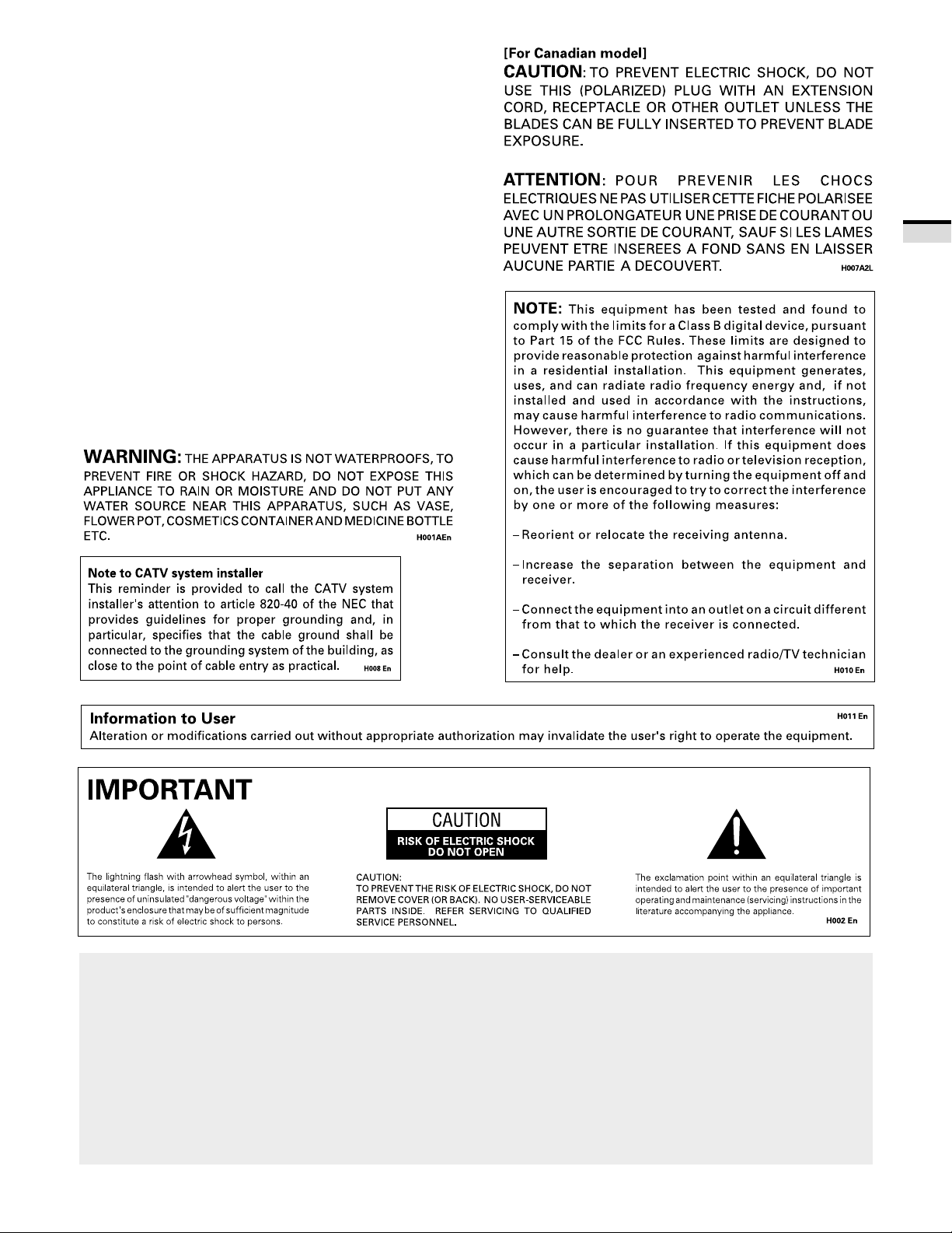
The following symbols are found in this
manual and on the labels on the product.
They alert the operators and service
personnel of this equipment to potentially
dangerous conditions.
This symbol refers to a hazard or unsafe
practice which can result in severe personal
injury or death.
WARNING
CAUTION
This symbol refers to a hazard or unsafe
practice which can result in personal injury
This symbol indicates an action that is
prohibited.
or property damage.
WARNING
IMPORT ANT SAFETY INSTRUCTIONS AND WARNINGS
• Read all of these instructions.
• Keep these instructions for later use.
• Follow all warnings and instructions marked on the Monitor .
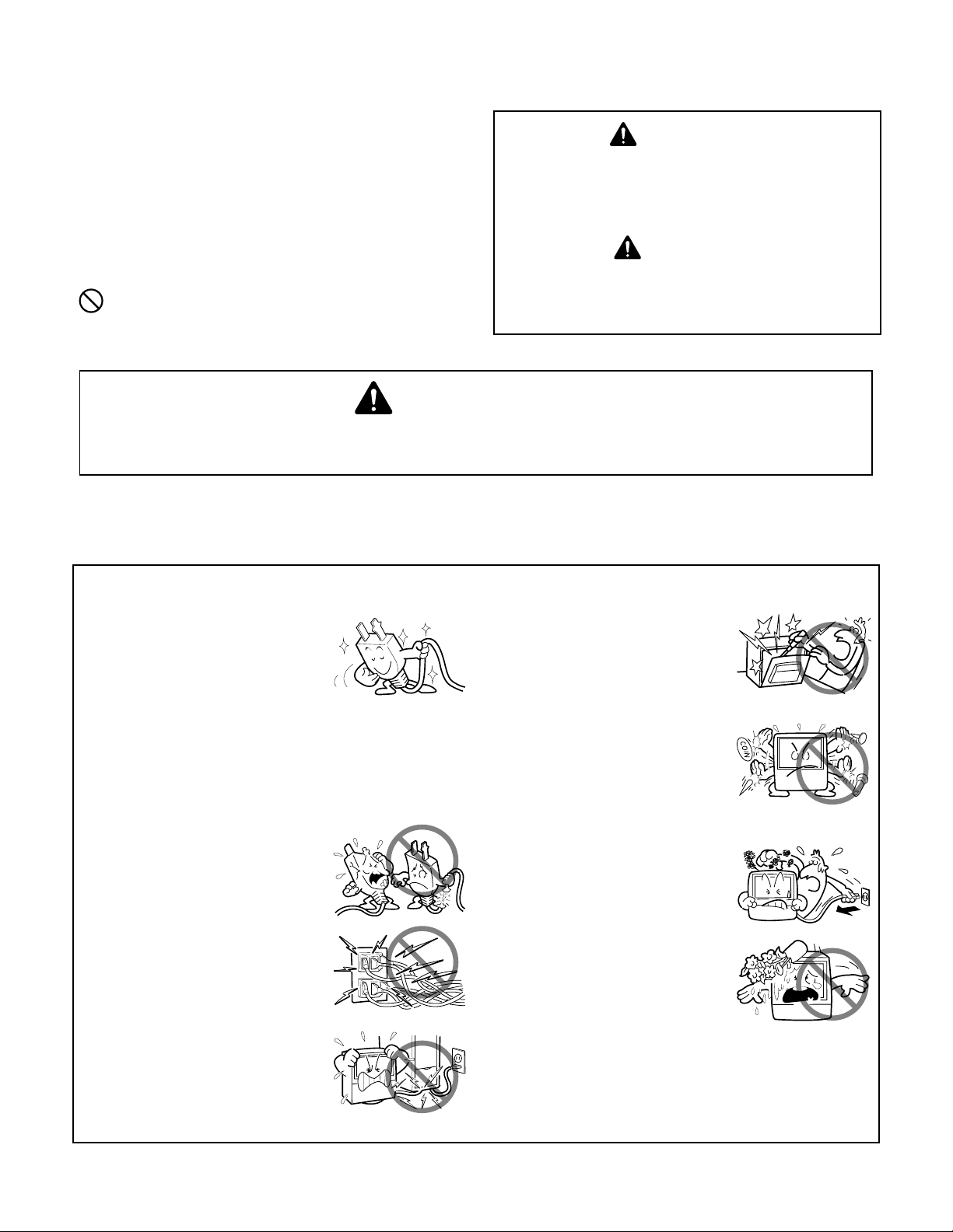
FOR YOUR PERSONAL SAFETY
1. This Monitor is equipped with a
polarized alternating current line
plug (a plug having one blade
wider than the other).
This plug will fit into the power
outlet only one way. This is a
safety feature.
If you are unable to insert the plug
fully into the outlet, try reversing
the plug. If the plug should still fail
to fit, contact your electrician to
replace your obsolete outlet. Do
not defeat the safety purpose of
the polarized plug.
2. If the power cord or plug becomes
damaged or frayed, unplug this
Monitor from the wall outlet and
refer to qualified service
personnel for servicing.
3. Do not overload wall outlets and
extension cords as this can result
in fire or electrical shock.
4. Do not allow anything to rest on
or roll over the power cord, and
do not place the Monitor where
the power cord maybe subject to
traffic or abuse. This may result
in electrical or fire hazard.
5. Do not attempt to service this
Monitor yourself as opening or
removing covers may expose you
to dangerous voltage or other
hazards. Refer all servicing to
qualified personnel.
6. Never push the objects of any kind
into this Monitor through cabinet
slots as they may touch
dangerous voltage points or short
out parts that could result in a fire
or electric shock. Never spill liquid
of any kind on the Monitor.
7. If the Monitor has been dropped
or the cabinet has been damaged,
unplug this Monitor from the wall
outlet and refer to qualified service
personnel for servicing.
8. If liquid has been spilled into the
Monitor , unplug the Monitor from
the wall outlet and refer servicing
to qualified service personnel.
4
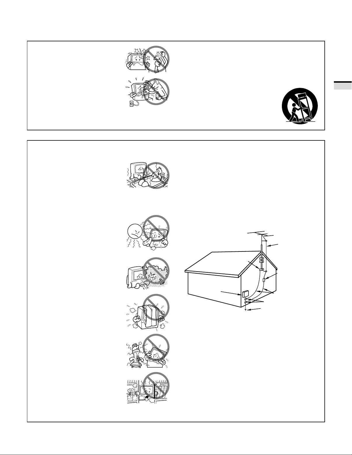
9. Do not subject your Monitor to
impact of any kind. Be particularly
careful not to damage the screen
surface.
11-1. Do not place this Monitor on an
unstable, uneven or an inclined
location. The Monitor may
overturn, causing serious injury
(to a person), and serious damage
10. Unplug the Monitor from the wall
to the appliance.
outlet before cleaning. Do not use
liquid cleaners or spray-type
cleaners. Use a damp cloth for
cleaning.
11-2. Be careful when placing the
Monitor on a cart to move it.
Quick stops, excessive force, and
uneven surfaces may cause the
Monitor and cart to overturn.
PROTECTION AND LOCATION OF YOUR HDTV PROJECTION MONITOR
12. • Do not use the Monitor near
water, for example, near a
bathtub, washbowl, kitchen sink,
or laundry tub, in a wet basement,
or near a swimming pool, etc.
• Never expose the Monitor to rain
water .
If the Monitor system has been
exposed to rain or water , unplug
the Monitor from the wall outlet
and refer servicing to qualified
service personnel.
13. Choose a place where light (artificial
or sunlight) does not shine directly
on the screen.
14. Avoid dusty places since the
buildup of dust inside the Monitor's
chassis may result in the
malfunctioning, when high
humidity persists.
15. • The Monitor has slots, or
openings in the cabinet for
ventilation purposes to ensure the
reliable operation of the Monitor ,
and to protect it from overheating.
These openings must not be
blocked or covered.
• Never cover the slots or openings
with cloth or other material.
• Never block the bottom
ventilation slots of the Monitor by
placing it on a bed, sofa, rug, etc.
• Never place the Monitor near or
over a radiator or heat register .
• Never place the Monitor in a built-
in enclosure such as a bookcase,
unless proper ventilation is
provided.
16. If an outside antenna is connected through other
equipment, be sure the antenna system is grounded so
as to provide protection against voltage surges and builtup static charges. In the U. S. A., section 810 of the
National Electrical Code, ANSI/NFPA 70, provides
information on proper grounding of the mast and
supporting structure, grounding of the lead-in wire to
an antenna-discharge unit, size of grounding
conductors, location of antenna-discharge unit,
connection to grounding electrode, and requirements
for the grounding electrode.
GROUND
CLAMP
ELECTRIC
SERVICE
EQUIPMENT
FIG. A
EXAMPLE OF ANTENNA GROUNDING IN
NATIONAL ELECTRICAL CODE INSTRUCTIONS
NEC-NATIONAL
ELECTRICAL CODE
ANTENNA
LEAD IN WIRE
ANTENNA
DISCHARGE UNIT
(NEC SECTION 810-20)
GROUNDING CONDUCTORS
(NEC SECTION 810-21)
GROUNDING CLAMPS
POWER SERVICE GROUNDING
ELECTRODE SYSTEM
(NEC ART 250, PAR T H)
INTRODUCTION
5
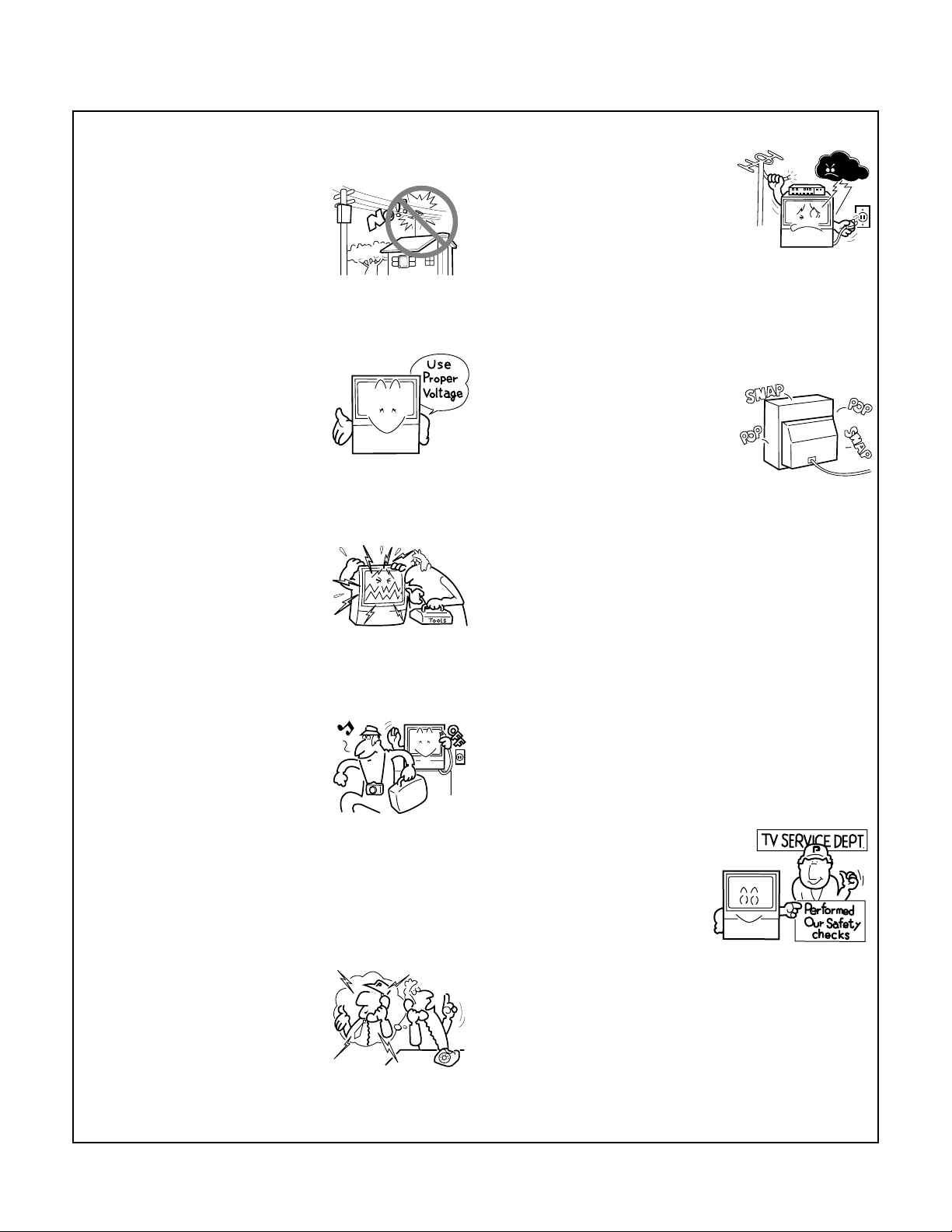
17. An outdoor antenna system
should not be located in the
vicinity of overhead power lines/
electric lights or power circuits, or
where it can fall onto such power
lines or circuits. When installing
an outdoor antenna system,
extreme care should be taken to
keep it from touching such power
lines or circuits as contact with
them might be fatal.
18. For added protection during a
OPERATION OF YOUR HDTV PROJECTION MONITOR
19. The Monitor should be operated
only from the type of power
source indicated on the marking
label. If you are not sure of the type
of power supply at your home,
consult your dealer or local power
company.
20. If you are unable to restore normal
operation by following the
detailed procedure in your
operating instructions, unplug it
from the wall outlet and refer to
qualified service personnel for
servicing. Do not adjust other
controls than those described in
this manual. Improper
adjustments may result in
damage and will often require
extensive work by a qualified
technician to restore the Monitor
to normal operation.
21. If your Monitor is to remain
unused for a period of time, for
instance, when you go on a
holiday, turn the Monitor 'off' and
unplug it from the wall outlet.
24. It is normal for some Monitor to
FOR SERVICING AND MODIFICATION
25. Do not use attachments not
26. When replacement parts are
27. Upon completion of any service
IF THE HDTV PROJECTION MONITOR
DOES NOT OPERATE PROPERLY
22. If you are unable to restore normal
operation by following the
detailed procedure in your
operating instructions, do not
attempt any further adjustment.
Unplug the Monitor and call your
dealer or service technician.
lightning storm, or when it is left
unattended and unused for long
periods of time, unplug the
Monitor from the wall outlet and
disconnect the antenna. This will
prevent damage due to lightning
and power-line surges.
make occasional snapping or
popping sounds, particularly
when being turned on or off. If the
snapping or popping is
continuous or frequent, unplug
the Monitor and consult your
dealer or service technician.
recommended by the Monitor's
manufacturer as they may result
in the risk of fire, electrical shock
or injury to persons.
required, be sure the service
technician uses replacement parts
specified by the manufacturer that
have the same characteristics as
the original part. Unauthorized
substitutions may result in fire,
electrical shock, or injury.
or repairs to the Monitor , ask the
service technician to perform
routine safety checks to determine
that the Monitor is in a safe
operating condition.
23. Whenever the Monitor is
damaged or fails, or there is a
distinct change in performance,
unplug the Monitor and have it
checked by a professional service
technician.
6

CONTENTS
INTRODUCTION
HOW TO USE THESE OPERA TING INSTRUCTIONS..................... 8
INST ALLING THE MONITOR ........................................................ 9
BASIC OPERA TIONS
BEFORE USE .............................................................................. 12
CONNECTING THE ANTENNA ................................................... 14
CONNECTING VIDEO/AUDIO EQUIPMENT ................................ 16
FRONT P ANEL FUNCTIONS ....................................................... 20
REMOTE CONTROL UNIT FUNCTIONS ..................................... 22
TO WATCH TV ............................................................................ 24
CHECKING THE MENU............................................................... 26
AUTO CHANNEL PRESET .......................................................... 28
CONVERGENCE ADJUSTMENT ................................................ 30
BASIC FUNCTIONS
PROGRAM BLOCK (V . CHIP) FUNCTION .................................... 32
CHANGING P ASSWORD............................................................ 39
CHANGING SCREEN SIZE .......................................................... 41
MUL TI-SCREEN FUNCTION ....................................................... 43
CLOSED CAPTION DECODE FUNCTION .................................... 45
CHANGING CHANNEL SET UP .................................................. 46
PICTURE ADJUSTMENTS .......................................................... 51
SOUND ADJUSTMENTS ........................................................... 59
RLS FUNCTION .......................................................................... 63
MUL TI-POINT CONVERGENCE ADJUSTMENT.......................... 64
V ARIOUS FUNCTIONS
CONNECTION WITH RECEIVER (1)............................................. 66
CONNECTION WITH RECEIVER (2)............................................. 69
CONNECTING THE SYSTEM REMOTE CONTROL ..................... 71
REMOTE CODE SET UP.............................................................. 72
OTHERS
MENU INDEX ............................................................................. 82
TROUBLESHOOTING ................................................................. 84
SPECIFICATIONS........................................................................ 86
7
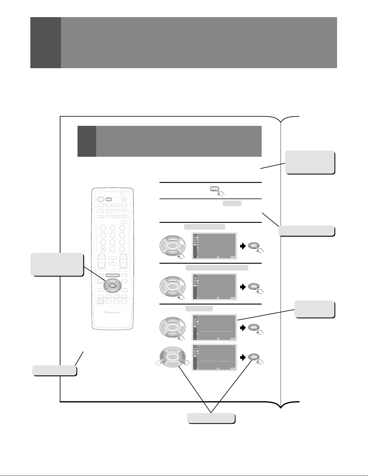
HOW TO USE THESE OPERA TING
INSTRUCTIONS
The following page is an example of the way that basic operating instructions are shown in this manual.
The explanation method varies from page to page.
The button(s) that
is/are used is/are
shown in dark gray.
Precautions etc.
AUTO CHANNEL PRESET
The broadcast frequencies that can be received depend on your area.
Memorize the broadcast stations that can be received in your area in the
presets.
Select TV .
TV CBL
DVD
VCR
/SAT
/LD
TV
/DTV
POWER
TV
INPUT
1 2 3 4
SELECT
SEARCH
SPLIT
SCREEN
MODE
SUB CH
FREEZE
ANT
DISPLAY
1 32
4 65
7 98
CH
ENTER
0
¢
CH
RETURN
MUTING
4
4
TV/SAT/DVD
MENU
5
SET/
2 3
ENTER
∞
FAVORITE CH
RECEIVER
INPUT
VOL
VOL
DTV/DVD TOP
MENU
DTV/SAT
GUIDE
DTV/(SAT)
INFO
VCR REC
VOL
Î
CH
EDIT/
LEARN
SOURCE
POWER
8
17 3¡
HDTV PROJECTION MONITOR
NOTE:
The CHANNEL SET UP cannot be selected unless the
function is set up for TV.
1
Press MENU and select SET UP
2
the 5 or ∞ button and then pressing SET/
ENTER. (Refer to page 26.)
Select CHANNEL SET UP in the same way.
3
5
SET/
2 3
ENTER
∞
Select AUTO CHANNEL PRESET .
4
5
SET/
2 3
ENTER
∞
Select ANTENNA , then select A or B.
5
5
SET/
2 3
ENTER
∞
5
SET/
2 3
ENTER
∞
TV
SET UP
CHANNEL S ET UP
CONVERGENC
PROGRAM B LO CK
RLS :OF F
CHANGE PASSWORD
SYSTEM IN /EOUT
USE: END: MENU
EXI T
SET UP
CHANNEL S E
SET UP
AUTO CHANN
SET UP
AUTO CHANN
T
AUTO CHANN
CHANNEL
FAVOR I E C
EXI T
ANTENNA : A
TV /CAB LEELMPORDEES:
AUTO PRES ET S TART
EXI T
ANTENNA : A B
TV /CAB LEELMPORDEES:
AUTO PRES ET S TART
EXI T
P
ETLADPDR/EDSEELT
HAUNNE L
USE: END: MENU
CATV STD
USE: END: MENU
CATV STD
USE: END: MENU
ET
ET
by using
SET/
ENTER
SET/
ENTER
SET/
ENTER
SET/
ENTER
Explanation of the
function on this
page.
Operating procedure
Screen during
operation
8
28
Buttons used
INST ALLING THE MONITOR
INSTALLATION PRECAUTIONS:
• Keep away from magnetic fields
The picture may be distorted if strong magnetic fields are
nearby. External speakers should be set at least 2 feet (60cm)
away from the Projection Monitor. Electric fans and other
motor driven appliances and toys may also be sources of
magnetism.
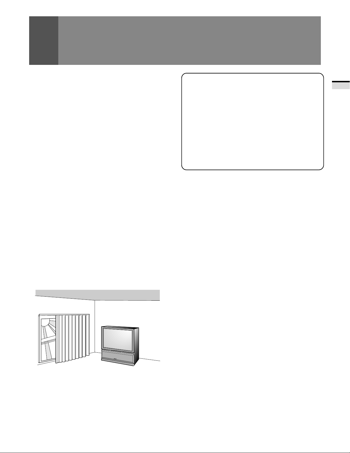
• Bright light or direct sunlight will dull the picture. Position
the Projection Monitor so that the screen faces away from
windows.
• While the Projection Monitor is operating, it is cooled by
airflow through ventilation holes in the rear and bottom.
Therefore, avoid placing it in a location where the cooling
airflow is hindered (e. g. against a wall).
• Avoid places subject to extremely high temperatures or
humidity, or to temperatures of 41°F (5°C) or lower. Also
avoid dusty places.
• If setting the Projection Monitor on a floor made of soft
material, make sure that the floor will not damaged by the
weight of the Projection Monitor .
• Do not put the Projection Monitor on a surface that is tilted,
unsteady or prone to shake or vibrate. A shaky or slanted
platform is dangerous.
• Cover shiny surfaces (floor and walls) with non reflective
materials (carpet, rugs, wallpaper , etc.).
CARE OF YOUR PROJECTION MONITOR
DO NOT :
• Do not use strong cleansers, solvents, polishes, or chemically
treated cloths to clean the screen or cabinet.
• Do not touch or scratch the screen.
• Do not fasten or place rubber or vinyl items on the Monitor .
• Do not stick adhesive tape onto the Monitor .
• Do not put any object on the Monitor .
DO:
• Use a soft cloth to dust the screen and cabinet.
• Handle the screen with care to avoid scratches or damages.
• Ask your dealer or a Pioneer authorized service center to
clean the interior of the monitor in your area if the picture
brightness is too low even with the max. level. This may be
caused by dust buildup inside.
INTRODUCTION
OPERA TING PRECAUTIONS
Optimum viewing distance
10 to 23 feet is the range recommended for viewing comfort.
Adjust room illumination
Excessively bright or dim lighting may strain your eyes. Draw
the curtains if necessary to shut out direct sunlight.
Condensation and picture blurring
• If the room temperature suddenly rises (or if the Projection
Monitor is moved from a cool place to a hot place),
condensation may form on the lenses resulting in picture
distortion or color fading. If this occurs, simply wait a while
(with the power switch ON) and the condensation will
disappear.
• A gradual change in temperature can prevent condensation
from forming.
9
INST ALLING THE MONITOR
HOW TO A TT ACH THE PROVIDED PROTECTIVE SCREEN
WE RECOMMEND A TT ACHING THE PROTECTIVE SCREEN BEFORE USING THE MONITOR.
To improve the image reproduction characteristics of the
monitor and to protect the screen from damage or dust, attach
the provided protective screen to the screen frame of the
monitor following the given procedure.
If you decide not to install the protective screen, attach the
upper and lower panel frames as indicated and attach the
corresponding trim. If the protective screen is not being used,
store it on a flat surface. Do not lean it against a wall, as it will
become warped. Keep the microform cushion and cardboard
container for screen storage. Please note that the monitor does
not use the side frame covers when the protective screen is
not attached to the monitor .
P ARTS INCLUDED FOR PROTECTIVE SCREEN INSTALLA TION:
1 PROTECTIVE SCREEN WITH EDGE GUARDS
2 PANEL FRAMES (MOUNTS)
2 SIDE FRAME COVERS (TRIMS)
2 FRAME COVERS (TRIMS)
10 or 6
Attach upper and lower panel frames as indicated then follow
step 5 on HOW TO A TT ACH THE PROTECTIVE SCREEN.
PANEL FRAME ATT ACHING SCREWS
(Screw quantity depend on model)
HOW TO A TT ACH UPPER AND LOWER TRIM ONLY
(FASTENERS)
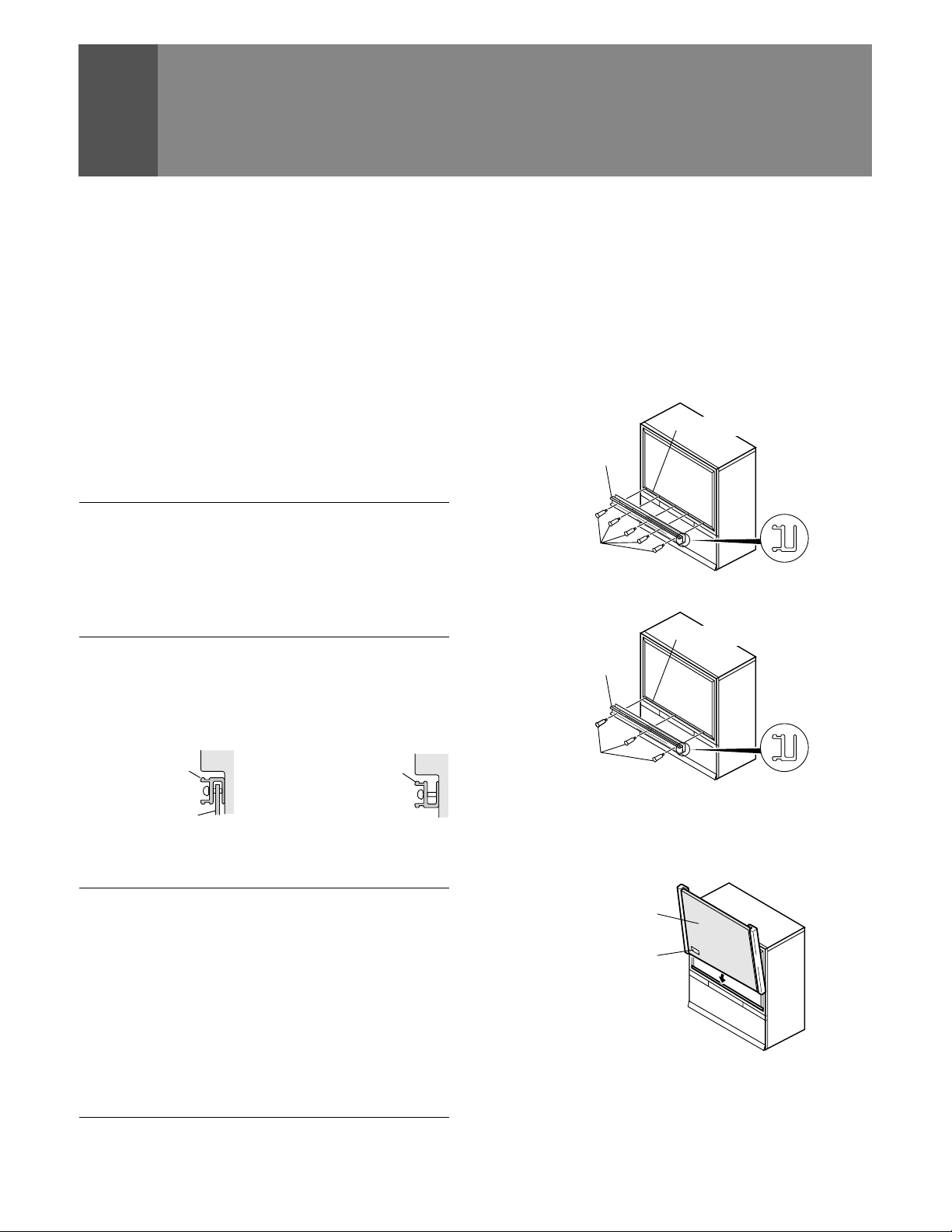
HOW TO A TT ACH THE PROTECTIVE SCREEN
1. Attach the lower panel frame to the monitor using five or
three screws starting with the center screw. (Screw quantity
depend on model.)
Do not overtighten the screws.
Overtightened screws may cause the protective screen to
warp.
Screen frame
Panel frame
Side view
Screws
Five screws type
Screen frame
Panel frame
Side view
<SIDE VIEW> <SIDE VIEW>
Panel frame Panel frame
Protective screen
When the protective screen
is attached.
When the protective screen
is not attached.
CAUTION: BEFORE A TT ACHING THE PROTECTIVE SCREEN
• Do not handle the screen by yourself. Have someone assist
you when attaching or carrying the screen to prevent any
accidents.
• Use a large-sized Phillips-head screwdriver for screwing and
unscrewing fasteners.
• Handle the screen with care to avoid injury and to avoid
leaving fingerprints on the screen surface.
• Carefully peel the vinyl covering from the front and back of
the protective screen. Inspect the screen and brush off any
plastic shavings or particles from the screen surface.
10
Screws
Three screws type
2. Insert the protective screen into the lower panel frame
making sure the labeled side is to be front and the label is
to be at the bottom left-hand corner .
Protective screen
Label
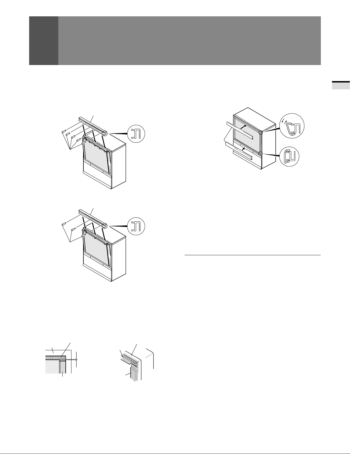
INST ALLING THE MONITOR
3. While holding the screen in place, attach the upper panel
frame to the screen and fasten five or three screws starting
with the center screw.
Do not overtighten the screws.
Overtightened screws may cause the protective screen to
warp.
Panel frame
Side view
Screws
Five screws type
Panel frame
Side view
Screws
5. Attach the remaining frame covers to the upper and lower
panel frames: first, insert the edge of the frame cover into
the outer groove of the panel frame, then starting at one
end, push the inner part of the frame cover over the inner
edge of the panel frame snapping it into place.
Upper frame cover
Remove
Attach
Frame cover
Lower frame cover
HOW TO REMOVE THE PROTECTIVE SCREEN
1) First, remove the frame covers only from the upper and
lower panel frames. Care must be taken to avoid scratching
the protective screen or frame covers.
2) Remove the screws from the upper panel frame and
remove the upper panel frame.
3) Remove the protective screen from the lower panel frame
and remove the lower panel frame. Reattach panel frames
and frame covers as indicated in HOW TO A TTACH UPPER
AND LOWER TRIM ONL Y.
INTRODUCTION
Three screws type
4. Attach side frame covers:
1) Peel off adhesive strip from rear side of the frame cover .
2) Attach side frame cover along the aluminium edge
guards leaving a space of approximately 0 to 1/32 in. (0
to 1 mm) from the upper panel frame.
Screen frame
Side frame cover
Upper panel frame
Upper panel
frame
0 to 1 mm
(0 to 1/32 in.)
Side frame
cover
Screen frame
NOTES FOR CARE AND CLEANING OF SCREEN:
• Do not hit or throw anything onto the protective screen, as a
damaged protective screen may cause injury.
• If the protective screen surface is dirty, wipe it with a cloth
dipped in warm water with mild detergent and then wrung
out. Wipe it dry with a soft, dry cloth.
• Never use paint thinner or other cleaners to clean the
protective screen as they may contain harmful chemicals
that will damage the finish of the screen.
11
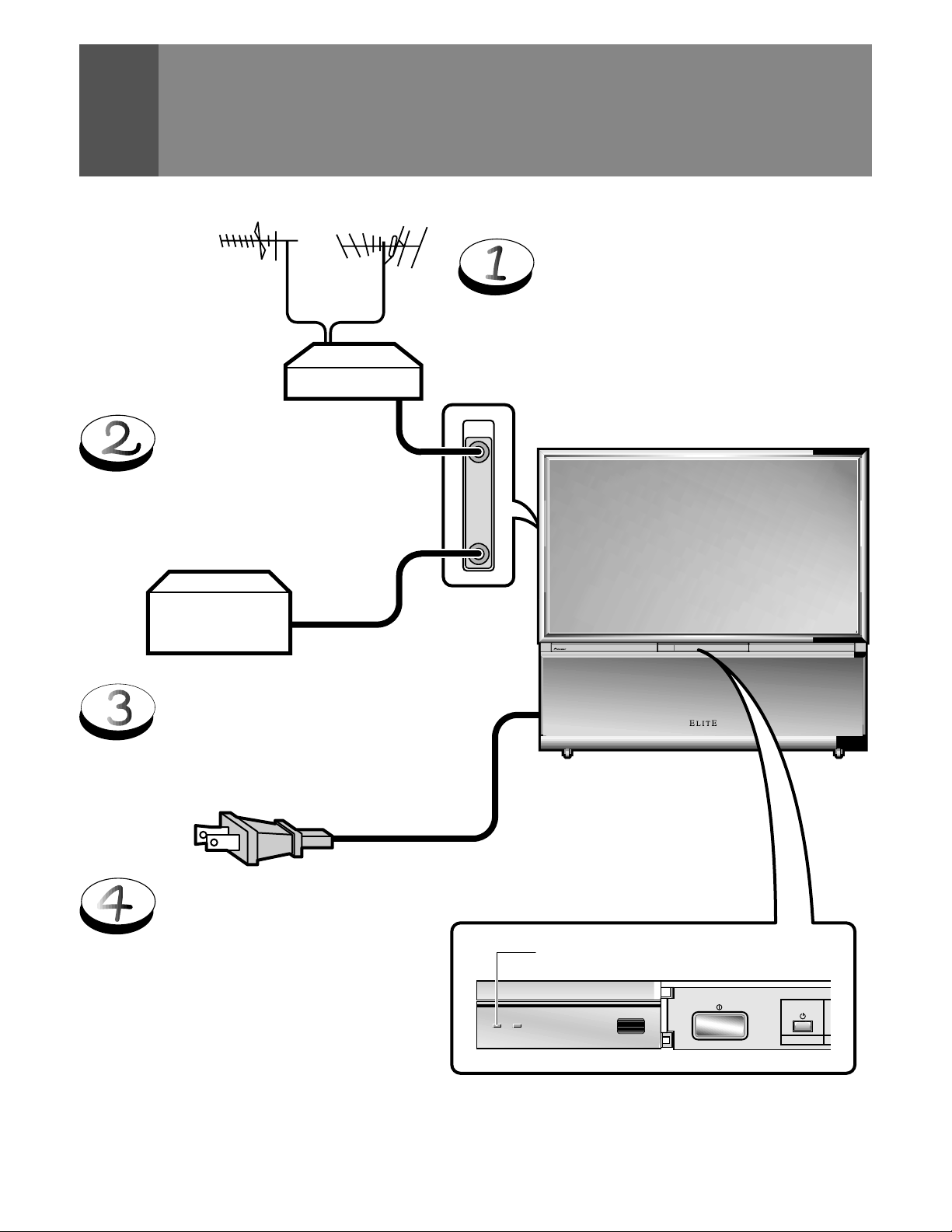
BEFORE USE
Before you watch the TV , perform the following procedure.
UHF VHF
Connect the cables of the VHF antenna
and UHF antenna to the ANTENNA A
terminal. (See pages 14 and 15)
Mixer
ANTENNA
/CABLE
A
Connect the CATV converter
to the ANTENNA B terminal.
(See pages 14 and 15)
CATV
converter
Connect the power cord to the
AC wall socket.
Turn on the MAIN POWER
button.
When the MAIN POWER is on, the red ST ANDBY
indicator lights up. In this state, the POWER
STANDBY/ON button or the TV Power button of
the remote control unit can be used to turn on and
off the Monitor .
B
STANDBY
Red indicator
ON
ROOM LIGHT
SENSOR
MAIN POWER
◊B√¿≥??ÙÛ◊B√¿≥??ÙÛ
STANDBY/ON
POWER
12
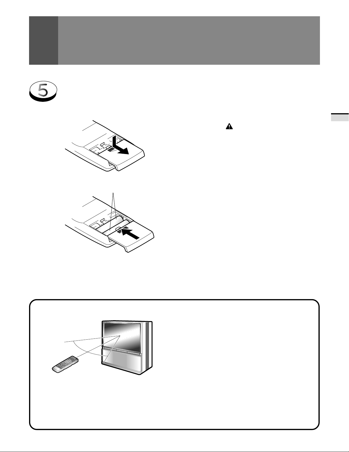
Inserting batteries into the remote control unit
BEFORE USE
1.
2.
T wo DURACELL
ALKALINE dry cell batteries
®
'AA' MN1500 1.5V
9
(
(
9
CAUTION
Incorrect use of batteries may lead to leakage or rupture.
Always be sure to follow these instructions.
A.
Never mix new and used batteries.
B.
Batteries of the same size may have different voltages
depending on their type. Do not mix different types of
batteries.
C.
Insert batteries so that the plus (+) and minus (– ) sides
are aligned according to the markings in the battery case.
D.
When not using the remote control unit for a long period
of time (1 month or more), remove the batteries from
the remote control unit to prevent leaking of battery fluid.
If battery liquid has leaked, thoroughly wipe the inside
of the case unit all liquid is removed, and then insert
new batteries.
E.
Do not charge, short, disassemble or throw the provided
batteries in a fire.
BASIC OPERA TIONS
Remote control operation range
30˚
30˚
23 feet (7m)
• Furniture and other obstacles may block the infrared light
beam so that it cannot reach the sensor behind the Projection
Monitor's screen.
• Performance of the remote control unit is adversely affected
by strong fluorescent light. Keep such lights away from the
screen.
Battery replacement
Replace the batteries when any of the following phenomena
is observed.
• The transmitting LED does not blink even when the TV Power
button is pressed.
• The remote control operation range has reduced.
When replacing the batteries, prepare new batteries before
removing the old batteries.
Be sure to close the battery case cover after battery
replacement.
NOTE:
• Even when batteries are removed, learned commands remain
in memory for about 15 minutes.
• If you remove the batteries, and press any button, the memory
is erased in a few seconds.
13
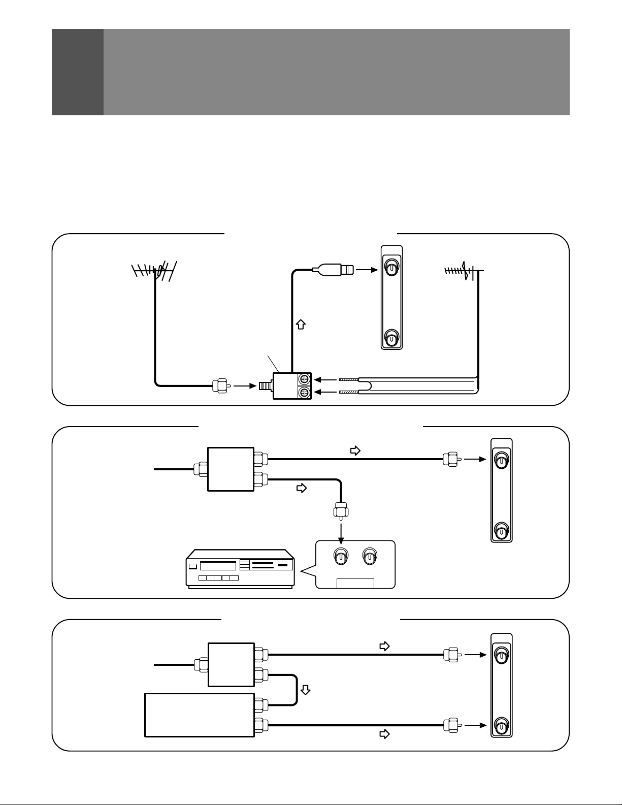
CONNECTING THE ANTENNA
• A good color picture depends on a good TV signal. So does
good multichannel (stereo program and SAP) sound. Ask
your dealer for advice on how to install your external antenna
to receive the best possible signal.
• If you subscribe to Cable TV or have a central antenna for
your building, you will not need an external antenna.
Connecting VHF/UHF antenna
VHF antenna
U/V mixer
VHF
Connecting VHF/UHF antenna with VCR
Antenna
or
Cable TV
Splitter
UHF
Connect the TV signal source to your Monitor properly.
Use a 75-ohm coaxial cable with an F-type connector and
connect the cable as shown in the illustration.
ANTENNA
/CABLE
A
B
UHF antenna
ANTENNA
/CABLE
A
14
Cable TV
Splitter
CATV converter
VCR
VCR
OUTIN
ANTENNA
Connecting the CA TV converter
B
ANTENNA
/CABLE
A
B
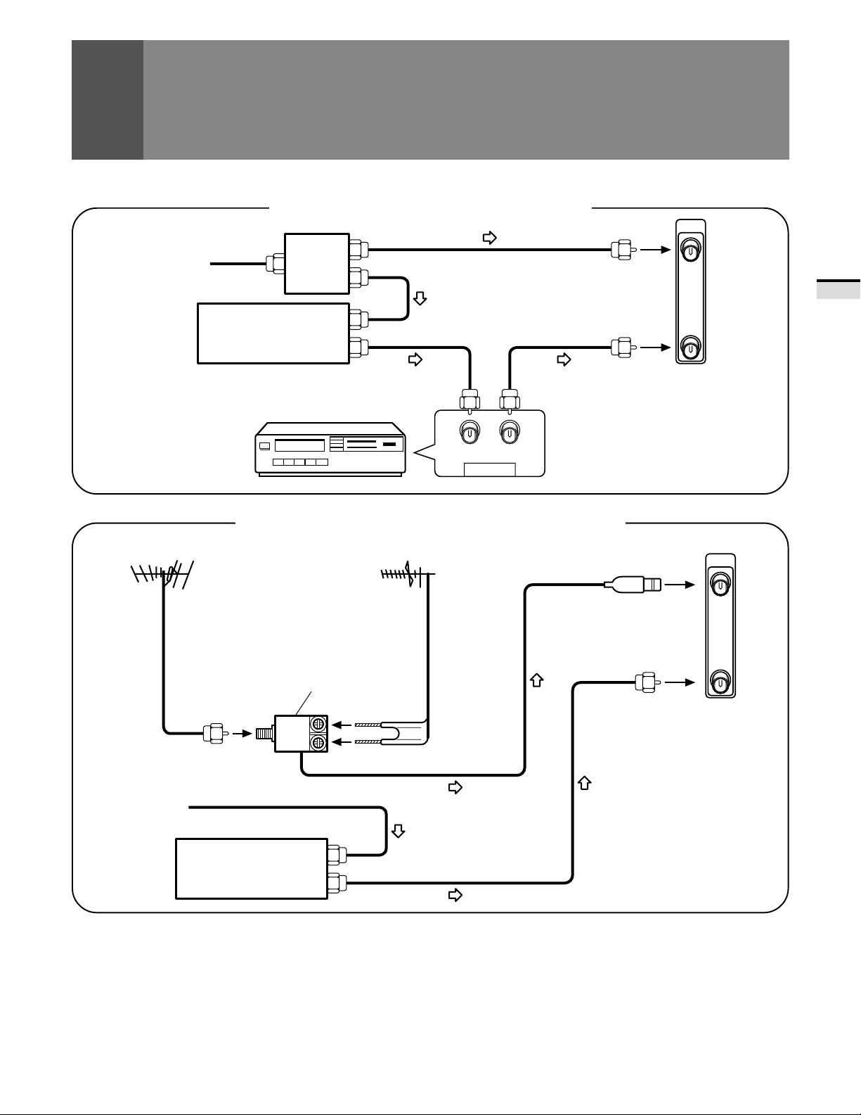
CONNECTING THE ANTENNA
Cable TV
VHF antenna
Connecting the CA TV converter with VCR
Splitter
CATV converter
VCR
VCR
OUTIN
ANTENNA
Connecting VHF/UHF antenna and CA TV converter
UHF antenna
ANTENNA
/CABLE
A
B
ANTENNA
/CABLE
A
BASIC OPERA TIONS
Cable TV
VHF
CATV converter
B
U/V mixer
UHF
15
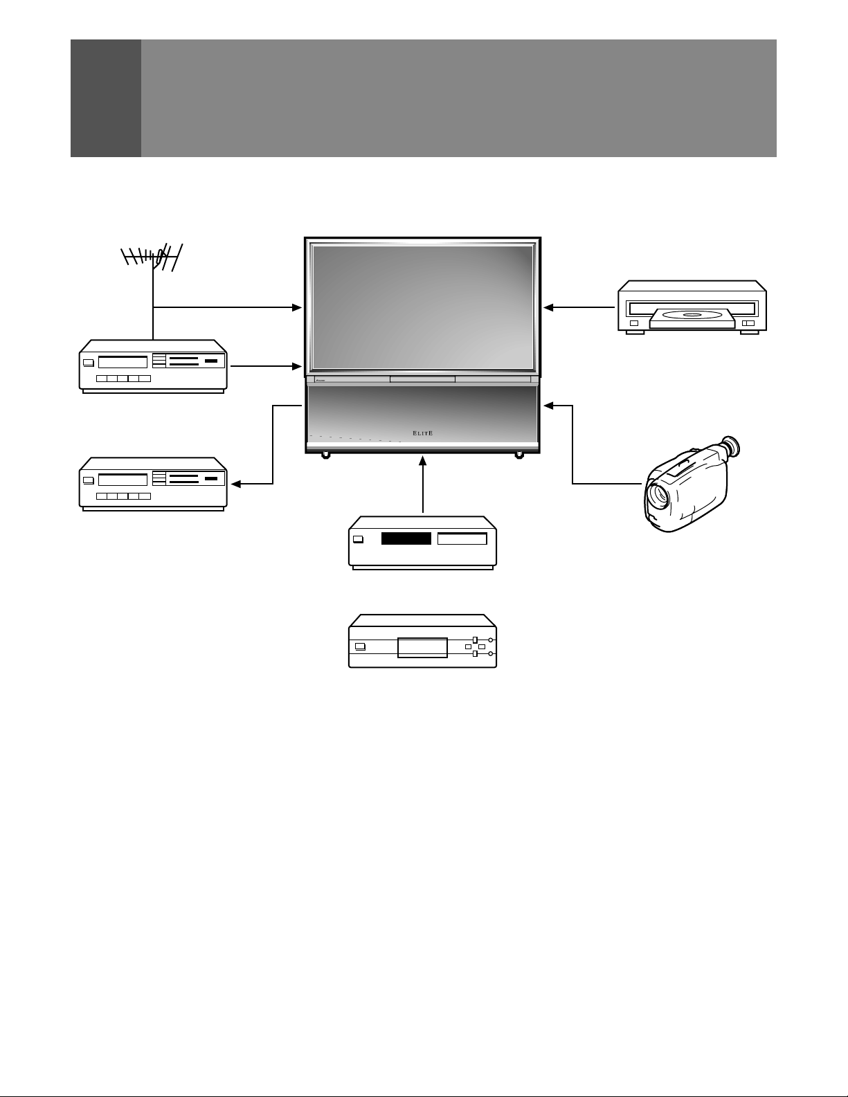
CONNECTING VIDEO/AUDIO
EQUIPMENT
DVD/LD player
VCR
VCR
VCR
VCR
Digital tuner
• Refer to the instructions of your VCR or DVD/LD player for
the detailed connections.
• Before making or changing connections, set the power
switch to off and unplug the power cord from the AC outlet.
• If both the VIDEO terminal (pin-jack type) and S-VIDEO
terminal are connected, the signals from the S-VIDEO
terminal will have priority.
◊B√¿≥??ÙÛ◊B√¿≥??ÙÛ
Video movie, etc.
SAT tuner
or
• Only the INPUT 1 and INPUT 2 jacks can input the component
video signal.
• When the component signal and other signals are input to
the INPUT 1 or INPUT 2 jacks, the component signal will be
given priority.
16
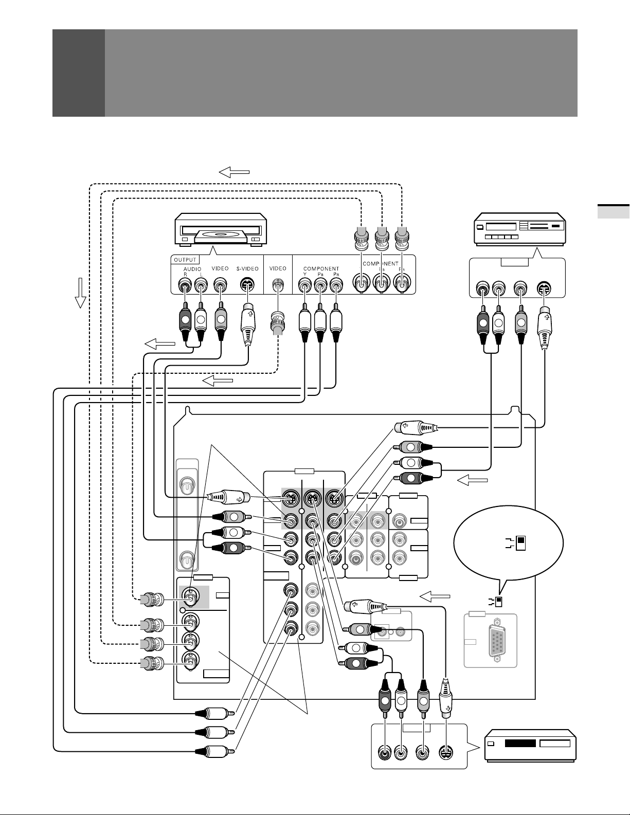
DVD/LD
player
CONNECTING VIDEO/AUDIO EQUIPMENT
SIGNAL
VCR
BASIC OPERA TIONS
VCR
SIGNAL
SIGNAL
R
V
L
SIGNAL
The video output can be connected
to BNC or to RCA types.
ANTENNA
/CABLE
A
V
S-VIDEO
VIDEO
L
Y
B/CB
P
PR/C
R
COMPONENT
VIDEO
VIDEO
R
AUDIO
COMPONENT
VIDEO
P
PR/C
Do not connect to INPUT 1 BNC
and INPUT 1 RCA simultaneously.
Picture will be scrambled.
B
INPUTS
INPUT 1
L
(MONO)
R
Y
B/CB
INPUTS
INPUT 1 INPUT 2
R
INPUT 3
OUTPUTS
V
L
R
TVMONITOR CENTER
FIXED/VAR
CONTROL
IN OUT
INPUT
OUTPUT
V
L
R
AUDIO
L
AUDIO
R
SIGNAL
SIGNAL
S-VIDEO/VIDEO
AUDIO
RL
R
S-VIDEO/VIDEO
RGB
RGB
INPUT
INPUT 3
RGB
OUTPUT
L
VIDEO
INPUT 3
SELECT
V
S-VIDEO
INPUT 3
SELECT
Component video output
of a DVD player can be
connected to both BNC or
RCA types.
R
L
AUDIO
RL
OUTPUT
VIDEO
V
Rear panel
SAT tuner
S-VIDEO
17
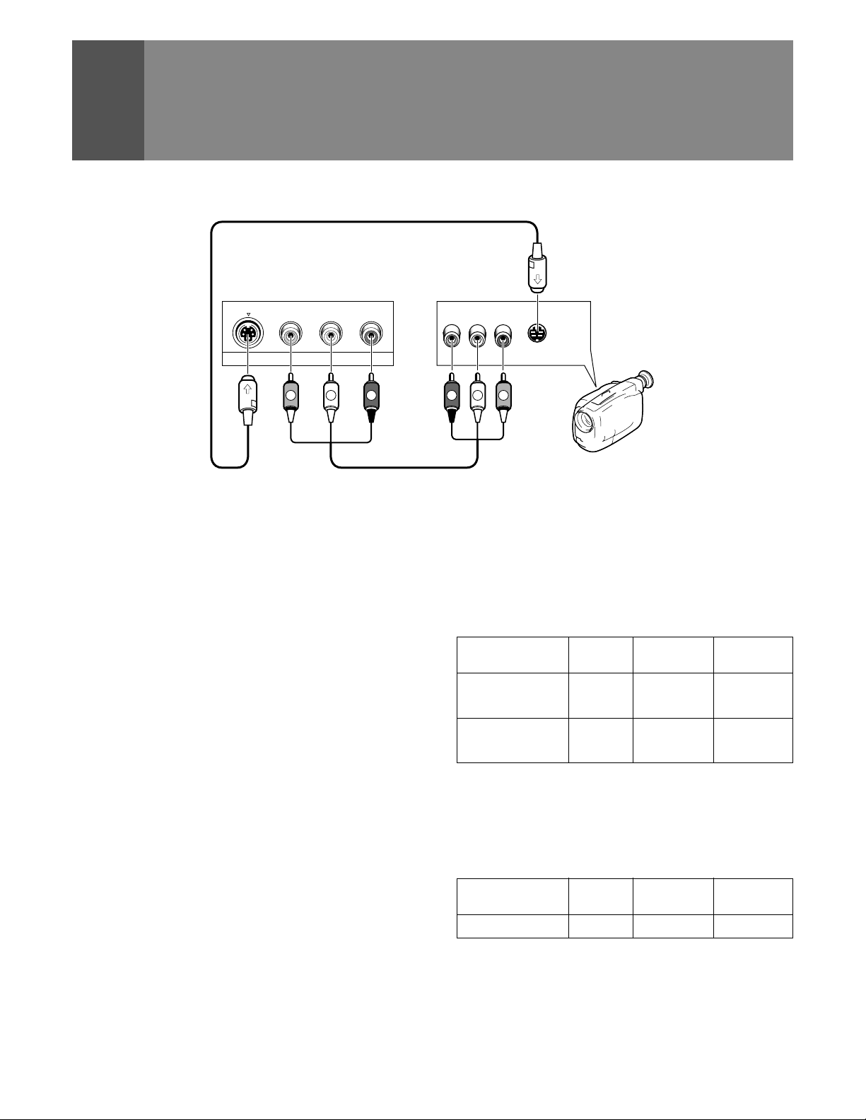
CONNECTING VIDEO/AUDIO EQUIPMENT
Front panel
S
-
VIDEO L-AUDIO-RVIDEO
INPUT 4
(MONO)
RLVIDEO
S-VIDEO
OUTPUT
L
V
R
INPUT jacks
There are 4 sets of inputs for VCR and DVD/LD players. Use
RCA-type pin plug cords (the same as those used in Hi-Fi
systems) for connections. When the audio source to be
connected is mono, connect the source to the L-(MONO) jack.
MONITOR OUTPUT jacks
These are used for connecting the monitor to a VCR for
recording, or for linking it to another monitor . These jacks output
the video and audio signals of the source currently selected
by the INPUT SELECT . Connect these output jacks to your VCR's
inputs. Connect the VCR's outputs to the monitor's VIDEO
inputs.
S-VIDEO INPUT jacks
• Inputs signals from a DVD/LD player that has an S-VIDEO
output jack.
• When the signal input from the S-VIDEO INPUT jack is output
from the MONITOR OUTPUT jack, the output signal will be
a composite of Y and C.
R
L
V
Video movie/VCR
COMPONENT VIDEO INPUT jack
Inputs three signals – Y, PB (CB) and PR (CR) – output from DVD
players and the like.
Input formats in which images can be received.
Format
Horizontal Vertical
frequency frequency
480 i 15.734 kHz 60 Hz
DVD player, etc.
Digital tuner , etc.
480p 31.468 kHz 60 Hz
1080 i 33.75 kHz 60 Hz
480p 31.468 kHz 60 Hz
RGB INPUT jack
Inputs five signals – R, G, B, H and V – output from digital
tuners and the like.
Input format in which images can be received.
Format
Digital tuner 1080 i 33.75 kHz 60 Hz
Horizontal Vertical
frequency frequency
18
NOTES:
• SPLIT screen, FREEZE screen and SEARCH screen functions
cannot be used when 1080i or 480p component signals are input.
• Signals from MONITOR OUTPUT jacks will not be output when
component signals or RGB signals are input.
• The RGB input jack is designed for use in connecting a digital
tuner with RGB signal output, and it should accordingly never
be used for connecting to a personal computer or other device.
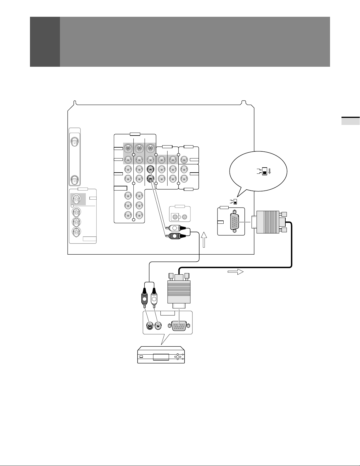
CONNECTING VIDEO/AUDIO EQUIPMENT
ANTENNA
/CABLE
A
A
B
INPUTS
INPUT 1
Y
P
B/CB
PR/C
R
COMPONENT
VIDEO
Rear panel
VIDEO
INPUTS
INPUT 1 INPUT 2
S-VIDEO
VIDEO
L
(MONO)
AUDIO
R
COMPONENT
VIDEO
Y
PB/C
B
PR/C
R
Do not connect to INPUT 1 BNC
and INPUT 1 RCA simultaneously.
Picture will be scrambled.
INPUT 3
MONITOR
OUTPUTS
TV
CONTROL
IN OUT
L
R
CENTER
FIXED/VAR
INPUT
OUTPUT
AUDIO
L
AUDIO
R
S-VIDEO/VIDEO
RGB
INPUT
INPUT 3
RGB
SIGNAL
SIGNAL
S-VIDEO/VIDEO
RGB
INPUT 3
SELECT
INPUT 3
SELECT
BASIC OPERA TIONS
R
L
OUTPUT
AUDIO
RL
Digital tuner
NOTE:
Setting the INPUT 3 SELECT switch to ‘ RGB’ will cause all S-Video
and composite images input from the INPUT 3 jack to be
suppressed. Similarly, setting the INPUT 3 SELECT switch to ‘ SVIDEO/VIDEO’ will cause all images input from the RGB input jack
to be suppressed.
RGB
19
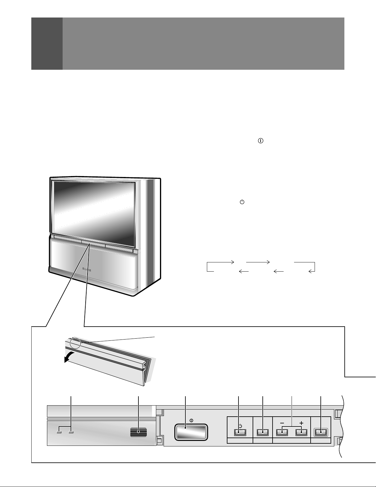
FRONT P ANEL FUNCTIONS
STANDBY/ON
POWER CHANNEL RETURN
A flip-down door conceals the INPUT 4 jacks. Push gently and
release, to open the door . T o close the door, lift it back up into
place.
NOTE:
If you accidentally pull the door, it may not shut properly. Push
the door back in to shut it.
1 POWER ST ANDBY/ON indicators
red: STANDBY
green: ON
2 ROOM LIGHT SENSOR (RLS)
Sensor to detect the room brightness.
3 MAIN POWER (OFF/ON) button
If the button is OFF , the power of the monitor is shut off and 4
STANDBY/ON button on the receiver or TV power on the
remote control will not function. Pressing the button again
will turn the monitor ON and the monitor enters the standby
mode. In the standby mode, you can turn on the monitor using
the 4 STANDBY/ON button on the monitor or TV power on
the remote control.
4 POWER ( STANDBY/ON) button
Switches the monitor between on and standby (note that the
monitor consumes a small amount of power (0.3 W) in standby
mode.
5 INPUT SELECT button
Press to select your program source. Each press of the INPUT
SELECT button changes the selection to the next source.
TV INPUT 1
INPUT 4 INPUT 3 INPUT 2
STANDBY
ON
While the menu is displayed, it performs the same operation
as the SET/ENTER button on the remote control.
6 CHANNEL buttons
Press plus (+) or minus (–) to tune to a higher or lower channel.
Only the preset channels can be tuned in using these buttons.
In some cases, the door may only open slightly when pushed.
In such cases, open the door with your finger as shown in the
PUSH
figure at left.
2 3 4 5671
MAIN POWER
SELECT
ROOM LIGHT
SENSOR
INPUT
20
VOLUME INPUT 4
S
-
VIDEO L-AUDIO-RVIDEO
(MONO)
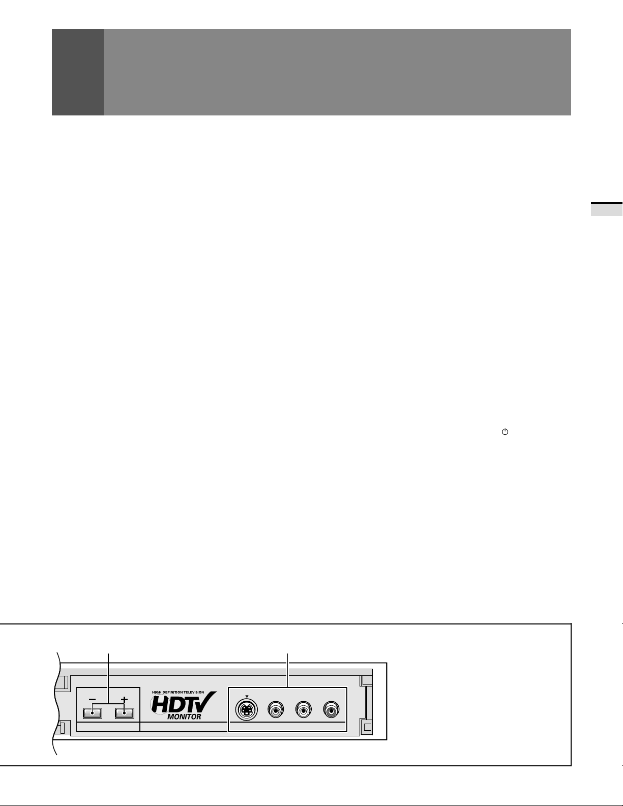
FRONT PANEL FUNCTIONS
7 RETURN button
Press to set the Projection Monitor to its initial mode.
Initial mode
Input selector: Set to TV .
TV channel: Remains at the last channel set.
VOLUME: Remains at the last setting.
MUTING: OFF
PICTURE
MODE: STD
Parameters: Set to 0.
3D Y/C LEVEL: 3
3D NR LEVEL: 3
COLOR TEMP: STD
FLESH TONE: ON
PURECINEMA: HQ
BLK ENHANCE: ON
SVM: HIGH
SOUND
MTS: MAIN
Parameters: Set to 0.
SURROUND: OFF
SUPER BASS: OFF
SCREEN
MODE: NA TURAL WIDE
V . POSITION: NOT USED
CC: OFF
RLS: OFF
SYSTEM IN/OUT
SPEAKER: NORMAL
AUDIO OUT : FIXED
SYSTEM MODE: OFF
9 INPUT 4 jacks
These inputs are for Video Movie and VCR. Use RCA-type pin
plug cords (the same as those used in Hi-Fi systems) and SVIDEO cords for connections. When the audio source to be
connected is mono, connect the source to the L-(MONO) jack.
CAUTION:
Do not press any operation button on the Projection Monitor
or the remote control unit while recording. Signals from the
MONITOR OUTPUT jacks may be temporarily interrupted
when a button is pressed.
A TTENTION
The Projection Monitor Receiver will not function properly in
the following cases.
• An electrical discharge in the CRT.
• Lightning storms.
• High static electricity environment.
• Poor voltage regulation in the power source.
If the Projection Monitor does not operate properly, reset it as
follows:
1. Turn off the power of the unit with the 3 MAIN POWER
button.
2. After approximately 1 minute, turn on the power with 3
MAIN POWER button and 4 POWER (
button.
If the normal operation cannot be restored after the above
treatment, immediately unplug the power cord and call your
nearest PIONEER-authorized service center .
STANDBY/ON)
BASIC OPERA TIONS
• When this button is pressed while adjusting the MUL TIPOINT convergence, the MULTI-POINT convergence
returns to the initial mode.
8 VOLUME buttons
Press plus (+) button to increase the volume, press minus (–)
button to decrease it.
8 9
NOTES:
•
On rare occasions, an electrical discharge may occur inside the
CRT*. It makes a short, sharp pop and either no sound is
produced or the volume level changes by itself. The SPLIT screen
and SEARCH screen functions will be cancelled automatically if
an electrical discharge occurs when this function is engaged.
*CRT: Cathode-ray Tube
•
When an electrical discharge distorts the screen and the TV
power has been automatically shut off, it can turn on.
If you notice any abnormality of the screen, turn off the MAIN
POWER button for a few minutes then turn it on.
This is not a malfunction.
21
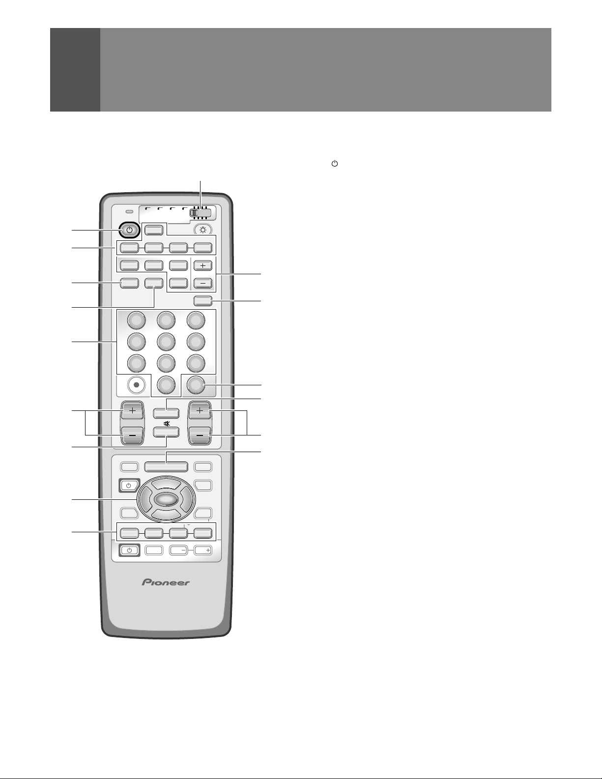
REMOTE CONTROL UNIT FUNCTIONS
Set the mode switch to TV .
1
TV Power button (STANDBY/ON)
T urns the power of the monitor on and off.
2 INPUT Selector buttons (TV , INPUT 1 to INPUT 4)
Press the button to select the source you wish to watch.
The screen will display your selection.
3 SCREEN MODE button
Press to select the SCREEN MODE. (Refer to page 41.)
4 ANT (antenna selector) button
Press to switch between ANTENNA-A and ANTENNA-B
when you wish to watch TV .
5 Direct channel selection buttons
Press the button (or buttons) that corresponds to the
channel that you wish to watch.
6 CH (channel) +, – button
Press plus (+) or minus (–) to tune in a higher or lower
channel. Only the preset channels can be tuned in using
these buttons.
7 MUTING button
Press to temporarily turn off the sound. Press again to return
to the previous volume level.
8 Select/Adjust/Set buttons (SET/ENTER, 2, 3, 5, ∞)
2, 3, 5, ∞: Press to select or adjust items on the menu
screen.
SET/ENTER: Press to activate the selected function.
9 FAVORITE CH buttons
These buttons call up the channels that have been assigned
to them.
1
2
3
4
5
6
7
8
9
Mode switch
TV CBL
TV
1 2 3 4
SPLIT
SCREEN
MODE
1
4
7
¢
CH
4
EDIT/
LEARN
SOURCE
POWER
2 3
8
17 3¡
INPUT
VCR
/SAT
/DTV
TV
INPUT
ANT
2 3
5
8
0
CH
RETURN
MUTING
TV/SAT/DVD
MENU
5
SET/
ENTER
∞
FAVORITE CH
RECEIVER
SELECTSEARCH
FREEZE
DVD
/LD
SUB CH
DISPLAY
6
9
CH
ENTER
VOL
DTV/DVD TOP
MENU
DTV/SAT
GUIDE
DTV/(SAT)
INFO
VCR REC
VOLVOL
0
-
=
~
!
@
22
Î
HDTV PROJECTION MONITOR

0 SPLIT/SEARCH screen buttons
SPLIT: Press to turn the SPLIT screen function on
and off.
SEARCH: Press to select the SEARCH screen mode.
SELECT : Selects the screen for switching the channel
or input source.*
FREEZE: When this button is pressed with the regular
screen, the screen will change to the SPLIT
screen and the picture at the time the button
was pressed will become the sub-picture,
displayed as a frozen image.
SUB CH +, – : Used to switch the channel for the sub-
picture of the SPLIT screen.
- DISPLAY button
Press to display the input source, channel, setting and other
screen indicators for a few seconds.
= CH ENTER button
Fix the selected channel with the direct channel selection
buttons.
~ CH RETURN (channel return) button
Press to switch between the current channel and the
channel you were watching immediately before.
REMOTE CONTROL UNIT FUNCTIONS
BASIC OPERA TIONS
! VOL (volume) +, – buttons
Press plus (+) button to increase the volume, press minus
(– ) button to decrease it.
Volume level will appear on the screen as numbers and a
bar graph. The maximum volume level is “63”.
The display will disappear from the screen after 2 seconds.
@ MENU button
Press to turn on the menu screen for use in function
selection.
Press again to return to normal TV screen.
* With the 9-SEARCH screen, the search picture’s input source
and channel cannot be switched.
23
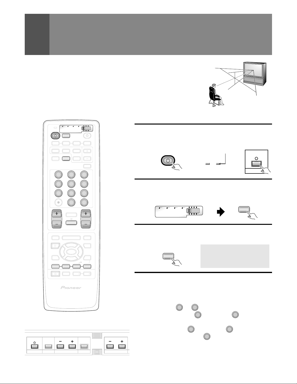
TO WA TCH TV
CA.TNAH2
Best Horizontal and Vertical V iewing Angle
• The optimum viewing angle is 140˚ in horizontal and 45˚ in vertical.
• W atch from at least 10 feet (3m) away from the screen (optimum viewing distance is 10 to
23 feet).
45˚
140˚
Remote control unit
TV
1 2 3 4
SPLIT
SCREEN
MODE
1
4
7
CH
EDIT/
LEARN
SOURCE
POWER
8
17 3¡
TV CBL
TV
SEARCH
ANT
/SAT
/DTV
INPUT
VCR
SELECT
FREEZE
DVD
/LD
2 3
5
8
0
¢
CH
RETURN
MUTING
MUTING
4
TV/SAT/DVD
MENU
5
SET/
2 3
ENTER
∞
FAVORITE CH
RECEIVER
INPUT
VOL
SUB CH
DISPLAY
6
9
CH
ENTER
VOL
DTV/DVD TOP
MENU
DTV/SAT
GUIDE
DTV/(SAT)
INFO
VCR REC
VOL
Î
Turn on the MAIN POWER button.
Turn on the POWER.
1
The green ON indicator lights up.
Control panel of the monitorRemote control unit
STANDBY
Green indicator
ON
TV
Set the mode switch to TV and
2
then press the TV button.
Remote control unit
TV CBL
/SAT
/DTV
Select antenna A or B.
3
Check the input signals at the ANTENNA A and B terminals.
Remote control unit
Select a channel.
4
There are three methods for this.
ANT
VCR
DVD
/LD
STANDBY/ON
POWER
TV
HDTV PROJECTION MONITOR
Control panel of the monitor
STANDBY/ON
SELECT
POWER
POWER CHANNEL RETURN VOLUME
INPUT
24
1 Select by pressing the number button
(Example)
Channel 5
5
→
CH
ENTER
(Or press 0 and then press 5 within 2 seconds
of during so.)
1
Channel 12 Press
during so. →
• After pressing a number button, even if you do not press the CH
ENTER button, the channel will be switched to the one selected within
2 seconds.
• Depending on the channel, this switch may occur immediately after
the number button is pressed.
and then press 2 within 2 seconds of
CH
ENTER
TO WATCH TV
SUPER HYPER UHF
7-13 14-69
W+1(37)
W+2(38)
W+3(39)
W+4(40)
W+5(41)
W+6(42)
W+7(43)
W+8(44)
W+9(45)
W+10(46)
7-13
J(23) Q(30)
K(24) R(31)
L(25) S(32)
M(26) T(33)
N(27) U(34)
O(28) V(35)
P(29) W(36)
TV
CATV
VHF L
2-6
2-6
(STD)
1-6
(HRC)
(IRC)
MID
A-5(95)
A-4(96)
A-3(97)
A-2(98)
A-1(99)
VHF H
A(14)
B(15)
C(16)
D(17)
E(18)
F(19)
G(20)
H(21)
I (22)
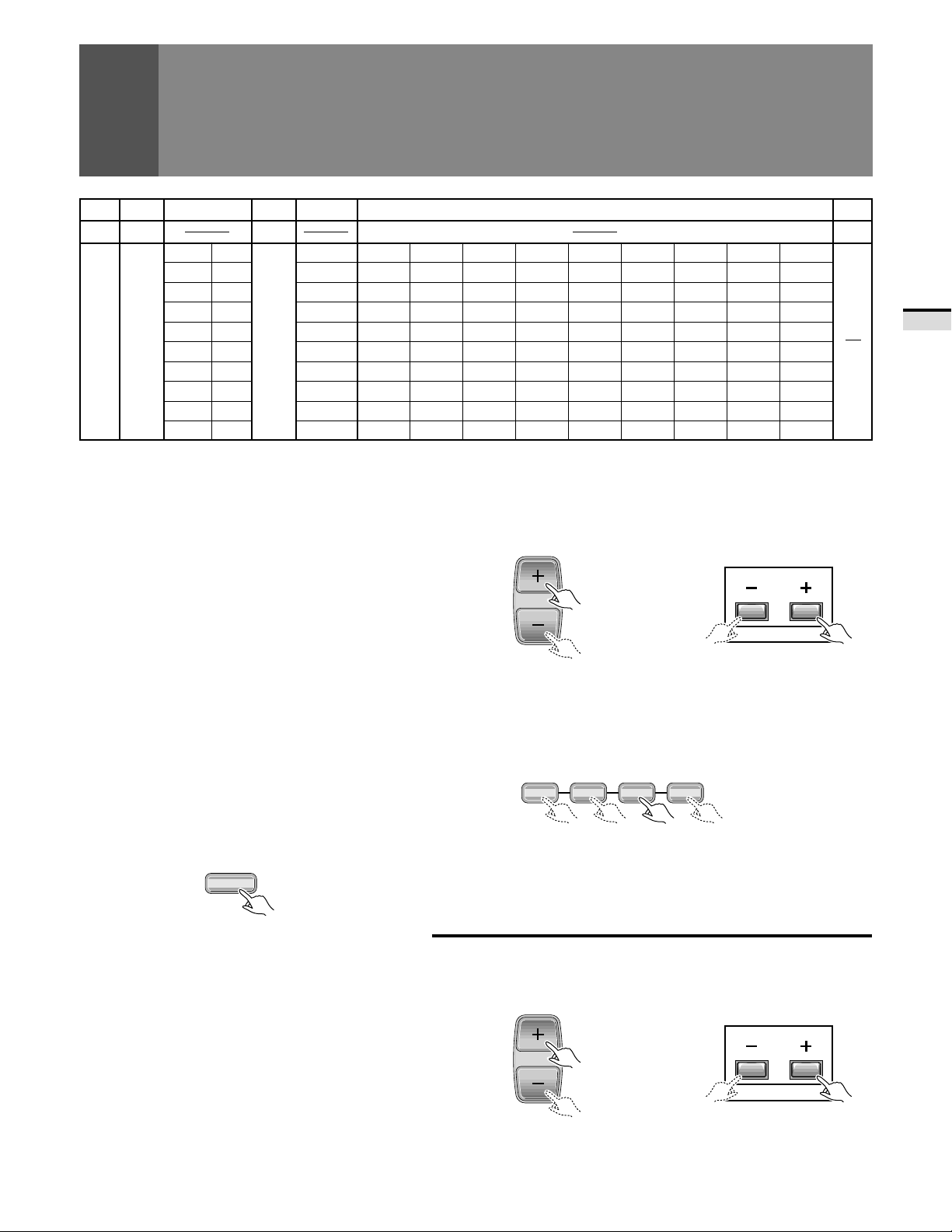
CABLE (CATV) CHANNEL
ASSIGNMENT TABLE
In the cable tuning mode, channels can only be assigned
to numbers 01 to 125. The specific channel number
assignments and the corresponding alphabet
designation are shown at the bottom left of the channel
table.
For example: Channel number '14' corresponds to
midband cable channel 'A'.
NOTE:
Cable (CA TV) services can vary according to area. The
channel number assignments shown in the channel
table may not correspond with the channel numbers
used by your local cable company. Direct tuning to
cable channels without using the cable company
converter 'or preselector' will depend on the specific
channels in use by the cable company. Direct tuning
to cable channels is limited to unencoded
(unscrambled) channels only. Check with your local
cable company for compatibility requirements.
W+11(47)
W+12(48)
W+13(49)
W+14(50)
W+15(51)
W+16(52)
W+17(53)
W+18(54)
W+19(55)
W+20(56)
W+21(57)
W+22(58)
W+23(59)
W+24(60)
W+25(61)
W+26(62)
W+27(63)
W+28(64)
W+29(65)
W+30(66)
W+31(67)
W+32(68)
W+33(69)
W+34(70)
W+35(71)
W+36(72)
W+37(73)
W+38(74)
W+39(75)
W+40(76)
W+41(77)
W+42(78)
W+43(79)
W+44(80)
W+45(81)
W+46(82)
W+47(83)
W+48(84)
W+49(85)
W+50(86)
W+51(87)
W+52(88)
W+53(89)
W+54(90)
W+55(91)
W+56(92)
W+57(93)
W+58(94)
W+59(
W+60(
100
101
W+61(
W+62(
W+63(
W+64(
W+65(
W+66(
W+67(
W+68(
W+69(
)
W+70(
)
102
103
104
105
106
107
108
109
110
111
W+71(
)
)
W+72(
)
W+73(
)
W+74(
)
W+75(
)
W+76(
)
W+77(
)
W+78(
)
W+79(
)
W+80(
112
113
114
115
116
117
118
119
120
121
W+81(
)
W+82(
)
W+83(
)
W+84(
)
)
)
)
)
)
)
122
123
124
125
2 Select using the TV CH+/– button
The channels will switch according to the order set by channel
preset (See page 28).
Control panel of the monitorRemote control unit
CH
CHANNEL
3 Select using the FAVORITE CH button
Select your desired channel from the 4 in the memory of each
button: blue, green, red and yellow.
Remote control unit
FAVORITE CH
17 3¡
)
)
)
)
BASIC OPERA TIONS
T o turn off the sound
Press the MUTING button.
MUTING
When mute is turned on, a volume indicator will
appear in red on the screen (and will disappear in
a few seconds).
If the MUTING button is pressed while a closed
caption signal is being received, CC/TEXT will be
displayed.
Press MUTING again to return to the previous
volume level.
Auto power off function
If the monitor is receiving no input signals in TV
mode, its power will turn off (go on standby) after
some time has passed.
• Each time the button is pressed, the channel will be changed
in order of the 4 channels in that button's memory.
• The desired channels can be set. (See page 49.)
• When you select a channel using the F AVORITE CH button,
step 3 (Select antenna A or B) is not necessary.
Adjust the volume.
5
VOL
Control panel of the monitorRemote control unit
VOLUME
25
CHECKING THE MENU
PICTURE
MO DE : USE R
NESS
(
THEATE
CONTRAST 0
5
2
3
01–
1–
BLACK LVL .
COLOR
TINT
SHARP
OTHER
EXI T
USE: END: MENU
R
)
PICTURE
L
SVM: OFF
3D Y/C EVEL 3
3D NR LEVEL : 3
COLOR TEMP : STD
F
F
F
FLESH TONE: OF
BLK ENHANCE : O
PUREC I NEMA : HQ
EXI T
USE: END: MENU
:
MT S : MA I N
BASS 0
5
2R
1–
TREBLE
BA LANCE
SURROUND
EXI T
USE: END: MENU
SOUND
:OFF
SUPE R ASBS
:OFF
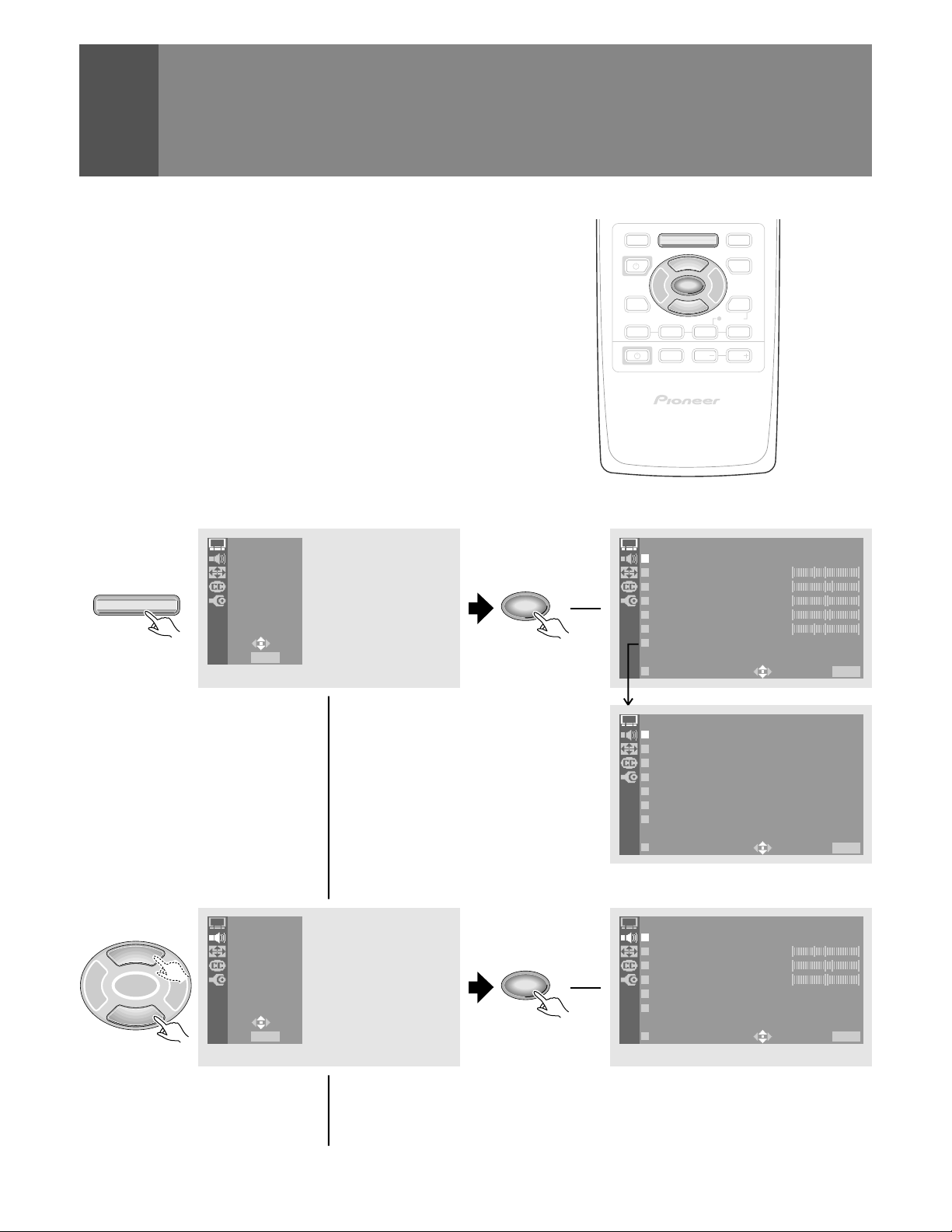
Press MENU on the remote control unit.
The MAIN MENU will be displayed on the screen.
Select the desired menu item using 5 or ∞ button of the remote
control unit, and press SET/ENTER button to perform the
desired operations or mater settings.
• When the menu screen appears, the mode will switch from
SCREEN to FULL. When all menu selections have been
made, the previous screen mode will be restored.
PICTURE
SOUND
SCREEN
TV/SAT/DVD
MENU
CC
SET UP
USE:
END: MENU
SET/
ENTER
EDIT/
TV/SAT/DVD
LEARN
SOURCE
POWER
2 3
8
FAVORITE CH
17 3¡
RECEIVER
INPUT
HDTV PROJECTION MONITOR
MENU
5
SET/
ENTER
∞
VOL
DTV/DVD TOP
MENU
DTV/SAT
GUIDE
DTV/(SAT)
INFO
VCR REC
VOL
Î
PICTURE adjustment menu (See page 51)
5
SET/
2 3
ENTER
∞
26
PICTURE
SOUND
SCREEN
CC
SET UP
USE:
END: MENU
SET/
ENTER
SOUND adjustment menu (See page 59)
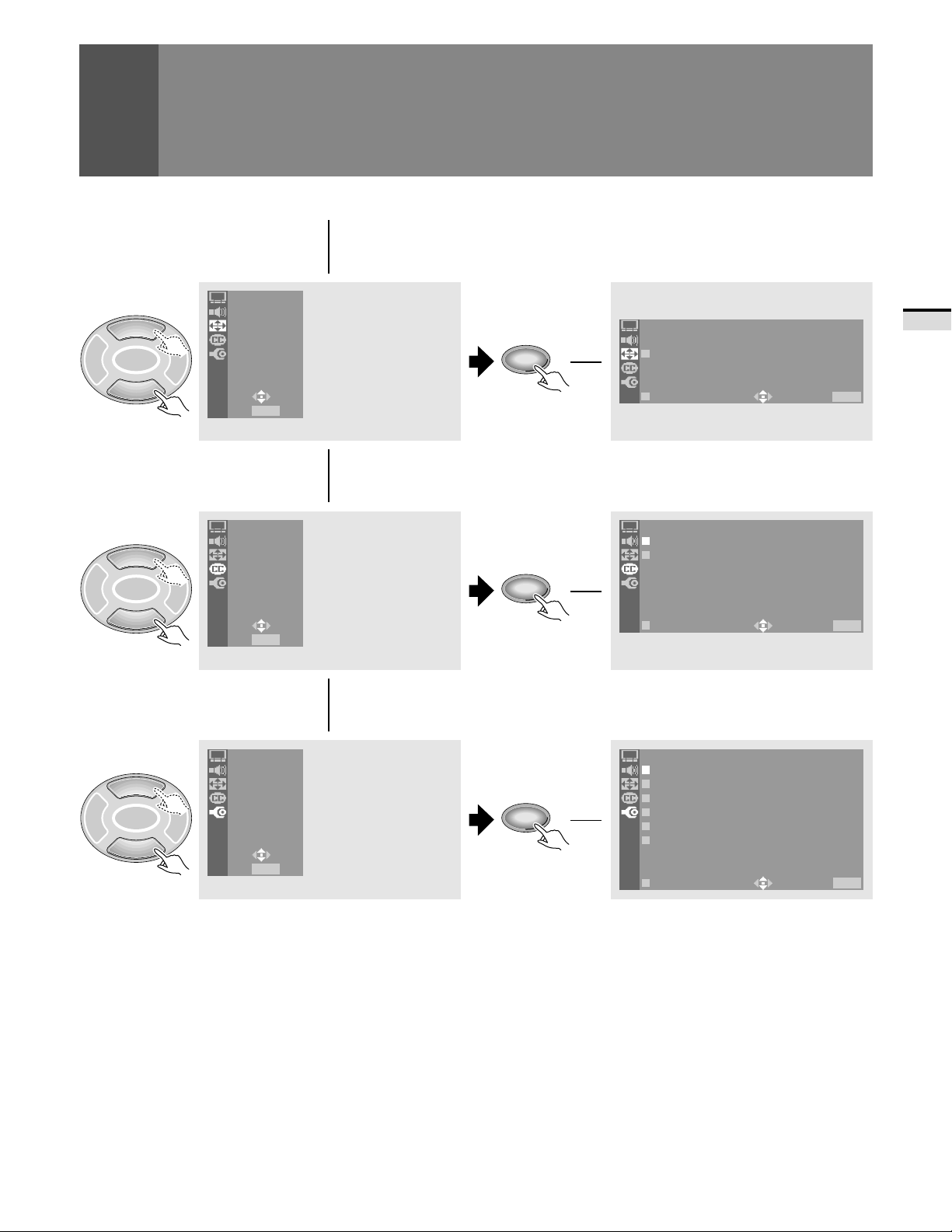
5
ICNEMAWIDE
V.POSITION:– 10
EXI T
USE: END: MENU
SCREEN
SET/
2 3
ENTER
PICTURE
SOUND
SCREEN
CC
SET UP
SET/
ENTER
CHECKING THE MENU
SCREEN setting menu (See page 42)
BASIC OPERA TIONS
∞
5
SET/
2 3
ENTER
∞
5
SET/
2 3
ENTER
∞
USE:
END: MENU
PICTURE
SOUND
SCREEN
CC
SET UP
USE:
END: MENU
PICTURE
SOUND
SCREEN
CC
SET UP
USE:
END: MENU
SET/
ENTER
SET/
ENTER
Closed Caption menu (See page 45)
CC
CC : O
MO DE : CCF–F2
EXI T
USE: END: MENU
SET UP menu
(See pages 28, 30, 34, 39, 46, 63 and 66)
SET UP
CHANNE L S ET UP
CONVERGE NC
PROGRAM B L OCK
RLS : OFF
CHANGE PASSWORD
SYSTEM I N/EOUT
EXI T
USE: END: MENU
On screen indicators
USE: Indicates in light cyan the buttons that can be used on
the menu screen displayed.
END: End is for turning off the menu screen by pressing the
MENU button.
EXIT : To return to the previous menu screen, use the 5 or ∞
button to move to EXIT and then press SET/ENTER.
27
 Loading...