

Pioneer PRO-610HD, PRO-510HD, SD-582HD5, SD-532HD5 Service Manual
PROJECTION MONITOR RECEIVER
PRO-610HD
PRO-510HD
SD-582HD5
SD-532HD5
THIS MANUAL IS APPLICABLE TO THE FOLLOWING MODEL(S) AND TYPE(S).
ORDER NO.
ARP3047
Type
PRO-610HDPRO-510HD SD-582HD5 SD-532HD5
KUXC/CA AC120V
KBXC –– –– –– AC120V
This service manual should be used together with the following manual(s):
Model No.
PRO-610HD
Model
ARP3051
Power Requirement
RemarksOrder No.
Remarks
CONTENTS
1. SAFETY INFORMATION....................................2
2. EXPLODED VIEWS AND PARTS LIST .............6
3. BLOCK DIAGRAM AND SCHEMATIC DIAGRAM
.......................................................22
4. PCB CONNECTION DIAGRAM .....................116
5. PCB PARTS LIST...........................................176
PIONEER CORPORATION 4-1, Meguro 1-Chome, Meguro-ku, Tokyo 153-8654, Japan
PIONEER ELECTRONICS SERVICE, INC. P.O. Box 1760, Long Beach, CA 90801-1760, U.S.A.
PIONEER ELECTRONIC (EUROPE) N.V. Haven 1087, Keetberglaan 1, 9120 Melsele, Belgium
PIONEER ELECTRONICS ASIACENTRE PTE. LTD. 253 Alexandra Road, #04-01, Singapore 159936
PIONEER CORPORATION 1999
O–ZZR NOV. 1999 Printed in Japan

PRO-610HD, PRO-510HD, SD-582HD5, SD-532HD5
1. SAFETY INFORMATION
This service manual is intended for qualified service technicians; it is not meant for the casual do-ityourselfer. Qualified technicians have the necessary test equipment and tools, and have been trained to
properly and safely repair complex products such as those covered by this manual.
Improperly performed repairs can adversely affect the safety and reliability of the product and may void the
warranty. If you are not qualified to perform the repair of this product properly and safely, you should not
risk trying to do so and refer the repair to a qualified service technician.
WARNING
This product contains lead in solder and certain electrical parts contain chemicals which are known to the state of
California to cause cancer, birth defects or other reproductive harm.
Health & safety code section 25249.6—Proposition 65
NOTES
(FOR CANADIAN MODEL ONLY)
Fuse symbols (fast operating fuse) and/or (slow operating fuse) on PCB indicate that replacement parts must
be of identical designation.
REMARQUE
(POUR MODÈLE CANADIEN SEULEMENT)
Les symboles de fusible (fusible de type rapide) et/ou (fusible de type lent) sur CCI indiquent que les pièces de
remplacement doivent avoir la même désignation.
1.1 SAFETY PRECAUTIONS
NOTlCE: Comply with all cautions and safety related notes
located on or inside the cabinet and on the chassis or picture
tube.
The following precautions should be observed:
1. Do not install, remove, or handle the picture tube in any
manner unless shatterproof goggles are worn. People
not so equipped should be kept away while picture tubes
are handled.
Keep picture tube away from the body while handling.
2. When service is required, even though the PROJECTION MONITOR RECEIVER an isolation transformer
should be inserted between power line and the set in
safety before any service is performed.
3. When replacing a chassis in the set, all the protective
devices must be put back in place, such as barriers,
nonmetallic knobs, adjustment and compartment
covershields, isolation resistor-capacitor, etc.
4. When service is required, observe the original lead
dress.
Extra precaution should be taken to assure correct lead
dress in the high voltage circuitry area.
5. Always use the manufacturer’s replacement components. Especially critical components as indicated on the
circuit diagram should not be replaced by other
manufacture’s.
Furthermore where a short circuit has occurred, replace
those components that indicate evidence of overheating.
6. Before returning a serviced set to the customer, the service technician must thoroughly test the unit to be certain
that it is completely safe to operate without danger of
electrical shock, and be sure that no protective device
built into the set by the manufacturer has become defective, or inadvertently defeated during servicing.
Therefore, the following checks should be performed for the
continued protection of the customer and service technician.
Leakage Current Cold Check
With the AC plug removed from 120V AC 60Hz source,
place a jumper across the two plug prongs. Turn the AC
power switch on. Using an insulation tester (DC 500V), connect one lead to the jumpered AC plug and touch the other
lead to each exposed metal part (input/output terminals,
screwheads, metal overlays, control shafts, etc.), particularly any exposed metal part having a return path to the
chassis. Exposed metal parts having a return path to the
chassis should have a minimum resistor reading of 0.3MΩ
and a maximum resistor reading of 5MΩ. Any resistor value
below or above this range indicates an abnormality which
requires corrective action. Exposed metal parts not having a
return path to the chassis will indicate an open circuit.
2
PRO-610HD, PRO-510HD, SD-582HD5, SD-532HD5
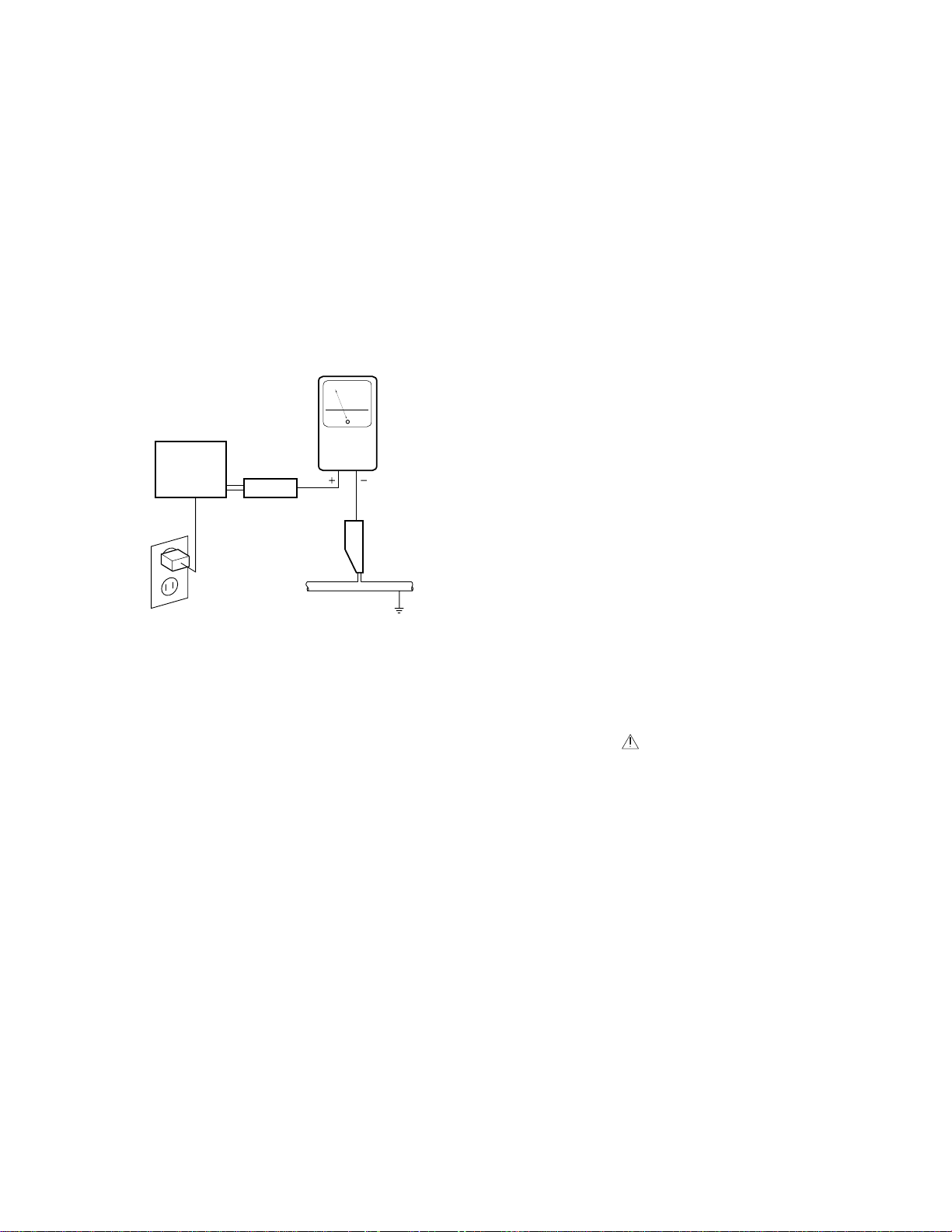
Leakage Current Hot Check
Plug the AC line cord directly into a 120V AC 60Hz outlet (
do not use an isolation transformer for this check). Turn the
AC power switch on.
Using a “Leakage Current Tester (Simpson Model 229
equivalent )”, measure for current from all exposed metal
parts of the cabinet ( input/output terminals, screwheads,
metal overlays, control shaft, etc. ), particularly any exposed
metal part having a return path to the chassis, to a known
earth ground (water pipe, conduit, etc.). Any current measured must not exceed 0.5mA.
Reading should
not be above
0.5 mA
Earth ground
Device
under
test
2-wire cord
Also test with
plug reversed
(Using AC adapter
plug as required)
Test all
exposed metal
surfaces
Leakage
current
tester
AC Leakage Test
ANY MEASUREMENTS NOT WITHIN THE LIMITS OUTLINED
ABOVE ARE INDICATIVE OF A POTENTIAL SHOCK HAZARD
AND MUST BE CORRECTED BEFORE RETURNING THE SET
TO THE CUSTOMER.
High V oltage
This set is provided with a X-ray protection for clearly indicating that voltage has increased in excess of a predetermined value. Comply with all notes described in this Service
Manual regarding this hold down circuit when servicing, so
that this X-ray protection may correctly by operated.
Serviceman Warning
In the status of the black picture ( video muting is being applied ) when no signal is input, high voltage of this set during
operation is less than 30.5kV. In case any component having some relation to the high voltage is replaced, confirm
that the high voltage is lower than 30.5kV in the status of the
black picture when no signal is input.
To measure H.V. use a high impedance H.V. meter.
Connect ( – ) to earth and ( + ) to the FBT anode cable connector.
X-radiation
TUBE: The primary source of X-radiation in this set is the
picture tube.
For continued X-radiation protection, the replacement tube
must be the same type as the original, PIONEER approved
type.
The picture tube (the CRT assy R, G, B ) use in this set
holds complete guarantee against X-ray radiation when the
X-ray is sealed (See page 4). Accordingly, when the current
in flowing to the picture tube (CRT assy R, G, B) be sure to
perform it by putting the tube into X-ray sealed applied state.
Avoid absolutely to flow the current to the picture tube (CRT
assy R, G, B) itself. Moreover, when the voltage of the high
voltage circuit becomes abnormally a little higher, the picture tube radiates X-rays. Accordingly, when servicing the
high voltage circuit be sure to replace as an assembly with
the DEFLECTION SERVICE assy in the manner in which
has been adjusted to perform normal operation.
1.2 PRODUCT SAFETY NOTICE
Many electrical and mechanical parts in PIONEER set have
special safety related characteristics. These are often not
evident from visual inspection nor the protection afforded by
them necessarily can be obtained by using replacement
components rated for higher voltage, wattage, etc. Replacement parts which have these special safety characteristics
are identified in this Service Manual.
Electrical components having such features are identified by
marking with a on the schematics and on the parts list in
this Service Manual.
The use of a substitute replacement component which does
not have the same safety characteristics as the PIONEER
recommended replacement one, shown in the parts list in
this Service Manual, may create shock, fire, X-radiation, or
other hazards.
Product Safety is continuously under review and new instructions are issued from time to time. For the latest information, always consult the current PIONEER Service
Manual. A subscription to, or additional copies of PIONEER
Service Manual may be obtained at a nominal charge from
PIONEER.
3
PRO-610HD, PRO-510HD, SD-582HD5, SD-532HD5
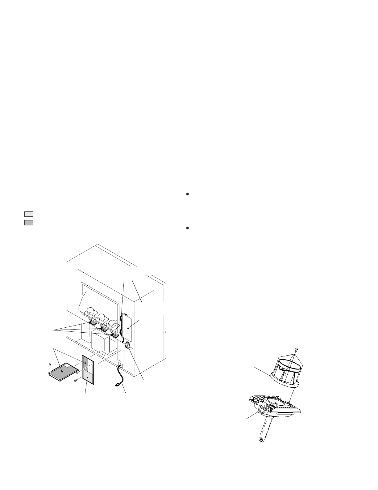
1.3 CHARGED SECTION, HIGH VOLT AGE GENERATING POINT
AND X-RAY PROTECTION
7 Charged section
The circuit in which the commercial AC power is used as it
is without passing through the power supply transformer. If
the charged section is touched, there is a risk of electric
shock. In addition, the measuring equipment can be damaged if it is connected to the GND of the charged section
and the GND of the non-charged section while connecting
the set directly to the commercial AC power supply. In this
case, be sure to connect the set via an insulated transformer
and supply the current.
7 Charged section
(Power supply primary side)
1. The primary side of the AC IN assy
2. AC power cord
3. The primary side of the POWER SUPPLY assy
4. AC power cord for DTV STB
(PRO-610HD, PRO-510HD Only)
: Part is the charged section.
: Part is the high voltage generating
points other than the charged section.
AC power cord for
DTV STB
PRO-610HD,
PRO-510HD
Only
High Voltage
generating point
High Voltage
generating point
7 High voltage generating point
The place where voltage is 100V is generated.
1.Charged seciton
DEFLECTION assy
(including FBT) (30.5kV, 1.2kV, 210V,135V)
2. POWER SUPPLY assy (135V)
3. R. CRT DRIVE assy (10.5kV, 210V)
4. G. CRT DRIVE assy (10.5kV, 210V)
5. B. CRT DRIVE assy (10.5kV, 210V)
6. CRT assy R (CRT service assy R) (30.5kV)
7. CRT assy G (CRT service assy G) (30.5kV)
8. CRT assy B (CRT service assy B) (30.5kV)
9. Focus variable resistor(VR1) (10.5kV)
10. Deflection yokes (L1, L2 and L3) Approx. (1100V at peak)
7 X-ray protection
Regarding the parts which are relative to radiation of Xrays (There is the danger to radiate X-ray from the individual CRT assy R, G, B), there are notifications of caution in the individual schematic diagrams. Be sure to read
them for safety’s sake.
The component parts for X-ray protection are as follows :
When the current flows to the CRT assy R, G, B, be sure
to perform it with these parts being attached. Protection
from the X-ray radiation is maintained in the state in which
these parts have been installed to the CRT assy. R, G, B.
Accordingly, never supply current only to the CRT assy R,
G, B.
Moreover, the anode voltage of the CRT assy R, G, B
should always be kept not higher than the predetermined
value (in the minimum brightness and picture state when
non signal input is less than 30.5kV). Be sure to drive the
CRT assy R, G, B by using a completely functional DEFLECTION assy which have been adjusted completely in
the combined state. (When the voltage abnormally becomes high, the X-ray protection circuit will operate.)
1. CRT assy R, G, B (Do not dismantle CRT assemblies
under any circumastances)
2. Each Lens assy
High Voltage
generating point
Charged section
Fig. 1 Charged section and high voltage generating point
4
AC Power cord
Each Lens Assy
CRT Assy R, G, B
Fig. 2 Component parts for X-ray protection

PRO-610HD, PRO-510HD, SD-582HD5, SD-532HD5
5
PRO-610HD, PRO-510HD, SD-582HD5, SD-532HD5
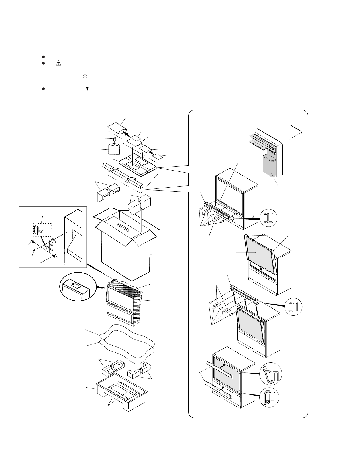
2. EXPLODED VIEWS AND PARTS LIST
NOTES : Parts marked by “ NSP ” are generally unavailable because they are not in our Master Spare Parts List.
The mark found on some component parts indicates the importance of the safety factor of the part.
Therefore, when replacing, be sure to use parts of identical designation.
÷ Parts marked by are important parts which relate in X-rays radiation.
If any of these parts need to be replaced, always replace with specified parts.
Screws adjacent to mark on the product are used for disassembly.
2.1 PACKING
13
15
11
12
14
PRO-610HD,
PRO-510HD
Only
22
(×12: PRO-610HD)
(×8 : PRO-510HD)
23
25 to 28, 32
29 to 31
3
16
24
Accessory
(PRO-610HD, PRO-510HD Only)
18
17
20
19
4
1
8
31
22
PRO-610HD Only
PRO-610HD
Only
Screen Frame
30
Side View
32
27
31
7
Side View
29
22
Remove
Attach
9
10
5
6
2
33
6
PRO-610HD, PRO-510HD, SD-582HD5, SD-532HD5
(1) PACKING PARTS LIST
Mark No. Description Part No. Mark No. Description Part No.
1 Upper Carton
2 Under Carton
3 Upper Pad L AHA2253
4 Upper Pad R AHA2254
5 Under Pad L AHA2255
6 Under Pad R AHA2256
NSP 7 Vinyl Sheet Upper
NSP 8 Packing Sheet
NSP 9 Packing Sheet Under
10 Vinyl Sheet Under
11 Remote Control Unit
12 Battery Cover AZN2401
NSP 13 Alkarine Dry Cell Battery AEX1018
(LR6,AA)
14 CU Packing Case AHC1032
15 Special Screw ABA1239
16 CONV. Attention Card
17 Operating Instructions
NSP 18 Caution Card ARM1057
NSP 19 Warranty Card
NSP 20 Poly Bag AHG1285
See Contrast table (2)
See Contrast table (2)
See Contrast table (2)
See Contrast table (2)
See Contrast table (2)
See Contrast table (2)
See Contrast table (2)
See Contrast table (2)
See Contrast table (2)
See Contrast table (2)
21 .................................
22 Special Screw
(Panel Frame Attaching Screw)
NSP 23 Wrapper Bag
NSP 24 Literature Bag AHG1222
25 Panel Case
26 .................................
27 Contrast Screen
28 Acrylic Caution Card
29 Frame Cover H
30 Frame Cover V Assy
31 Panel Frame H
32 Panel Frame V
NSP 33 Under Cushion A
See Contrast table (2)
See Contrast table (2)
See Contrast table (2)
See Contrast table (2)
See Contrast table (2)
See Contrast table (2)
See Contrast table (2)
See Contrast table (2)
See Contrast table (2)
See Contrast table (2)
(2) CONTRAST TABLE
PRO-610HD, PRO-510HD, SD-582HD5 and SD-532HD5 are constructed the same except for the following:
Mark
Symbol and DescriptionNo.
PRO-610HD PRO-510HD SD-582HD5 SD-532HD5 SD-532HD5
KUXC/CA KUXC/CA KUXC/CA KUXC/CA KBXC
1 Upper Carton AHD3045 AHD3046 AHD3049 AHD3050 AHD3050
2 Under Carton AHD3047 AHD3048 AHD3047 AHD3048 AHD3048
NSP 7 Vinyl Sheet Upper AHG1288 AHG1095 AHG1288 AHG1095 AHG1095
NSP 8 Packing Sheet AHG1230 AHG1120 AHG1230 AHG1120 AHG1120
NSP 9 Packing Sheet Under AHG1290 AHG1235 AHG1290 AHG1235 AHG1235
10 Vinyl Sheet Under AHG1289 AHG1234 AHG1289 AHG1234 AHG1234
11 Remote Control Unit (CU-SD110) AXD1448 AXD1448 AXD1449 AXD1449 AXD1449
(CU-SD110) (CU-SD110) (CU-SD111) (CU-SD111) (CU-SD111)
16 CONV. Attention Card ARM1173 ARM1173 ARM1174 ARM1174 ARM1174
17 Operating Instructions (English) ARB1527 ARB1527 ARB1528 ARB1528 ARB1528
NSP 19 Warranty Card ARY1026 ARY1026 ARY1050 ARY1050 Not used
NSP 20 Poly Bag AHG1285 AHG1285 AHG1285 AHG1285 Not used
22 Special Screw ABA1280 ABA1280 Not used Not used Not used
NSP 23 Wrapper Bag AHG1076 AHG1076 Not used Not used Not used
25 Panel Case AHB1215 AHB1216 Not used Not used Not used
27 Contrast Screen AAK2749 AAK2750 Not used Not used Not used
28 Acrylic Caution Card ARH1167 ARH1167 Not used Not used Not used
29 Frame Cover H AAP1613 AAP1614 Not used Not used Not used
30 Frame Cover V Assy AAP1617 AAP1619 Not used Not used Not used
31 Panel Frame H AAP1629 AAP1630 Not used Not used Not used
32 Panel Frame V AND1169 AND1167 Not used Not used Not used
NSP 33 Under Cushion A AHA2258 AHA2260 AHA2258 AHA2260 AHA2260
Part No.
Remarks
7
PRO-610HD, PRO-510HD, SD-582HD5, SD-532HD5
2.2 FRONT VIEW (1/2)
For SD-582HD5,
SD-532HD5
For PRO-610HD, PRO-510HD
2
3
4
For SD-582HD5, SD-532HD5
2
1
4
5
3
5
1
3
4
3
4
5
3
31
5
For PRO-610HD,
PRO-510HD
4
5
11
31
6
7
8
14
12
5
4
14
SD-582HD5,
SD-532HD5
Only
29
PRO-610HD,
PRO-510HD
Only
15
27
30
4
21
5
10
9
11
7
For PRO-610HD, PRO-510HD
25
24
For SD-582HD5, SD-532HD5
20
7
20
28
7
24
23
14
4
5
4
5
14
6
7
2519 24
2519 24
7
13
16
17
16
19
24
18
8
PRO-610HD, PRO-510HD, SD-582HD5, SD-532HD5
(1) FRONT VIEW (1/2) PARTS LIST
Mark No. Description Part No. Mark No. Description Part No.
1 Grille
2 Badge
NSP 3 Catcher A
4 Magic Tape AEC1349
5 Screw ABA1271
6 Side Cover
7 Special Screw ABA1240
8 Side Panel Assy L
9 Side Panel Assy R
10 Door Assy
11 Blind Plate
12 Catcher F2M AEC1609
13 Front Panel Assy
14 Catch B
15 Power Knob
16 Screw ABZ40P080FZK
17 FRONT INPUT Assy
18 POWER SW Assy AWZ6467
19 FRONT CONTROL Assy AWZ6462
20 Screw
See Contrast table (2)
See Contrast table (2)
See Contrast table (2)
See Contrast table (2)
See Contrast table (2)
See Contrast table (2)
See Contrast table (2)
See Contrast table (2)
See Contrast table (2)
See Contrast table (2)
See Contrast table (2)
See Contrast table (2)
See Contrast table (2)
NSP 21 Switch Holder ANG2313
22 .................................
23 Screw AMZ30P060FZK
24 Screw APZ30P080FZK
25 LED DPO Assy
26 .................................
27 Control Sheet
28 Indicator Panel L
29 Indicator Panel R
NSP 30 Front Shield ANK1502
31 Special Screw
See Contrast table (2)
See Contrast table (2)
See Contrast table (2)
See Contrast table (2)
See Contrast table (2)
(2) CONTRAST TABLE
PRO-610HD, PRO-510HD, SD-582HD5 and SD-532HD5 are constructed the same except for the following:
Mark Remarks
Symbol and DescriptionNo.
PRO-610HD PRO-510HD SD-582HD5 SD-532HD5
1 Grille AMM3003 AMM3004 AMR3173 AMR3174
2 Badge AAM1081 AAM1081 AAM1088 AAM1088
3 Catcher A ANZ-241 ANZ-241 Not used Not used
6 Side Cover AMR3107 AMR3107 Not used Not used
8 Side Panel Assy L AMB2662 AMB2664 Not used Not used
9 Side Panel Assy R AMB2663 AMB2665 Not used Not used
10 Door Assy AAN1461 AAN1461 AAN1459 AAN1457
11 Blind Plate AMM2933 AMM2933 AMM3009 AMM3009
13 Front Panel Assy AMB2666 AMB2666 Not used Not used
13 Control Panel Not used Not used AMB2657 AMB2657
14 Catch B AEC1507 AEC1507 ANZ–242 ANZ–242
15 Power Knob AAD4105 AAD4105 Not used Not used
17 FRONT INPUT Assy AWZ6466 AWZ6466 AWZ6471 AWZ6471
20 Screw ABA1239 ABA1239 Not used Not used
25 LED DPO Assy AWZ6463 AWZ6463 AWZ6470 AWZ6470
27 Control Sheet Not used Not used AMB2751 AMB2751
28 Indicator Panel L Not used Not used AMB2752 AMB2752
29 Indicator Panel R Not used Not used AMB2753 AMB2753
31 Special Screw Not used Not used ABA1249 ABA1249
Part No.
9
PRO-610HD, PRO-510HD, SD-582HD5, SD-532HD5
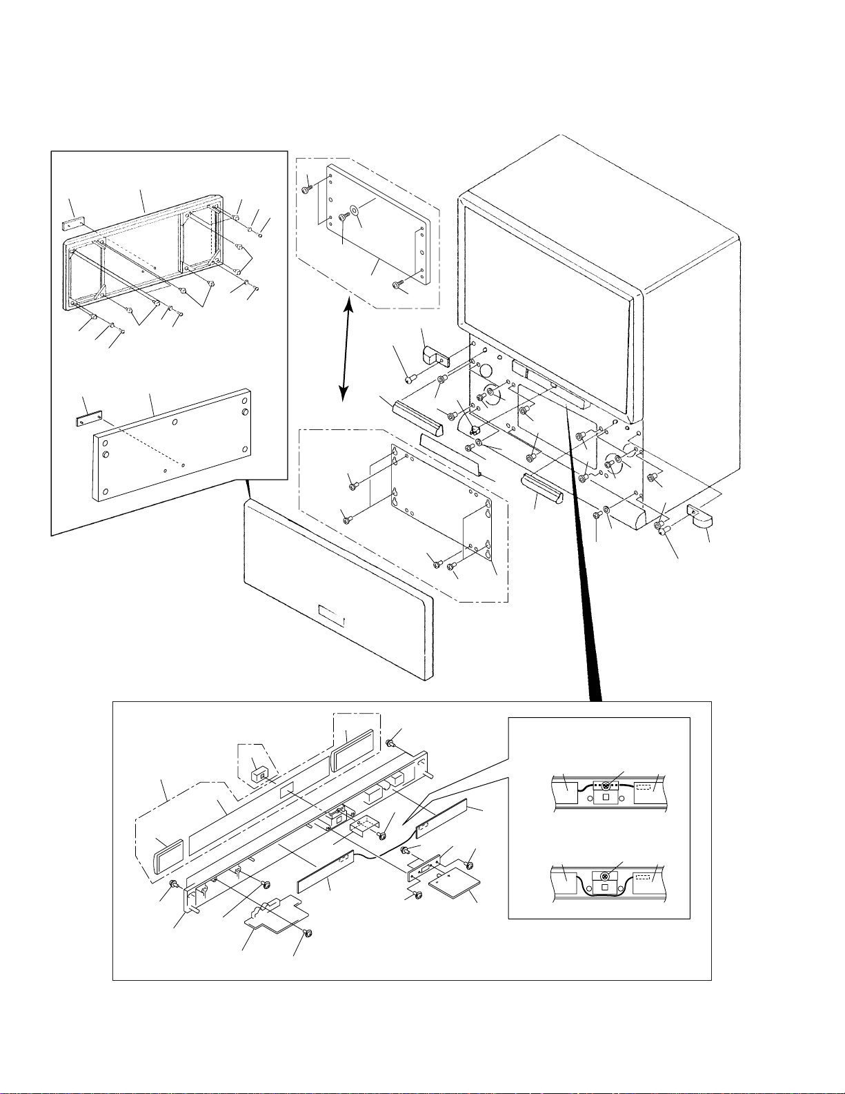
2.3 FRONT VIEW (2/2)
27
PRO-610HD,
PRO-510HD
Only
28
9
20
24
21
20
SD-582HD5,
SD-532HD5
Only
9
18
SD-582HD5,
SD-532HD5
Only
12
4
29
10
28
10
15
13
10
28
14
16
PRO-610HD,
PRO-510HD
Only
9
10
14
16
9
SD-582HD5,
SD-532HD5
Only
10
5
2
10
10
3
14
16
1
11
10
10
10
6
7
13
10
10
17
30
10
18
23
22
8
8
PRO-610HD
Only
PRO-610HD
22
Only
8
8
8
22
25
8
22
8
19
PRO-610HD
Only
8
22
8
26
22
22
PRO-610HD,
PRO-510HD
8
Only
PRO-610HD, PRO-510HD, SD-582HD5, SD-532HD5
(1) FRONT VIEW (2/2) PARTS LIST
Mark No. Description Part No. Mark No. Description Part No.
1 Lenticular Sheet
2 Screen Holder Top
3 Fresnel
NSP 4 Upper Cabinet Metal
NSP 5 Mirror Upper Stay L ANG2004
NSP 6 Mirror Upper Stay C ANG2006
NSP 7 Mirror Upper Stay R ANG2005
8 Screw
NSP 9 Screen Side Fitting
10 Special Screw ABA1240
11 Screw ACZ40P080FMC
12 Contrast Screen
13 Cone Speaker APV1021
14 Caster AMR2547
NSP 15 VR Holder ANG1956
See Contrast table (2)
See Contrast table (2)
See Contrast table (2)
See Contrast table (2)
See Contrast table (2)
See Contrast table (2)
See Contrast table (2)
26 Screen Frame Assy
27 Screen Holder Low
28 Screw BYC35P160FZK
29 Focus VR (VR1) ACX1096
30 Screw BBZ30P080FZK
See Contrast table (2)
See Contrast table (2)
16 Special Screw ABA1273
NSP 17 CRT Front Holder ANG2118
18 Screw M5 ABA1189
NSP 19 Under Screen Metal B
20 Mirror Frame V
21 Mirror
NSP 22 Upper Screen Metal B
NSP 23 Under Screen Metal A
24 Mirror Frame H
NSP 25 Upper Screen Metal A
See Contrast table (2)
See Contrast table (2)
See Contrast table (2)
See Contrast table (2)
See Contrast table (2)
See Contrast table (2)
See Contrast table (2)
(2) CONTRAST TABLE
PRO-610HD, PRO-510HD, SD-582HD5 and SD-532HD5 are constructed the same except for the following:
Mark Remarks
Symbol and DescriptionNo.
PRO-610HD PRO-510HD SD-582HD5 SD-532HD5
1 Lenticular Sheet AMR3184 AMR3185 AMR3178 AMR3179
2 Screen Holder Top ANG2369 ANG2370 ANG2363 ANG2364
3 Fresnel AMR3186 AMR3187 AMR3180 AMR3181
4 Upper Cabinet Metal ANG2000 ANG2000 ANG2358 ANG2358
8 Screw
9 Screen Side Fitting ANG1993 ANG1993 ANG2366 ANG2362
12 Contrast Screen Not used Not used AAK2747 AAK2748
NSP 19 Under Screen Metal B ANG2009 ANG2009 ANG2361 ANG2361
20 Mirror Frame V ANG2373 ANG2374 ANG2373 ANG2374
21 Mirror AMR3188 AMR3189 AMR3188 AMR3189
NSP 22 Upper Screen Metal B ANG2002 ANG2002 ANG2360 ANG2360
BYC40P160FMC BYC40P160FMC BYC40P140FZK BYC40P140FZK
Part No.
NSP 23 Under Screen Metal A ANG2003 ANG2003 ANG2361 ANG2361
24 Mirror Frame H ANG2371 ANG2372 ANG2371 ANG2372
NSP 25 Upper Screen Metal A ANG2001 ANG2001 ANG2359 ANG2359
26 Screen Frame Assy AAP1611 AAP1612 AAP1607 AAP1608
27 Screen Holder Low AAP1621 AAP1622 AAP1609 AAP1610
11

PRO-610HD, PRO-510HD, SD-582HD5, SD-532HD5
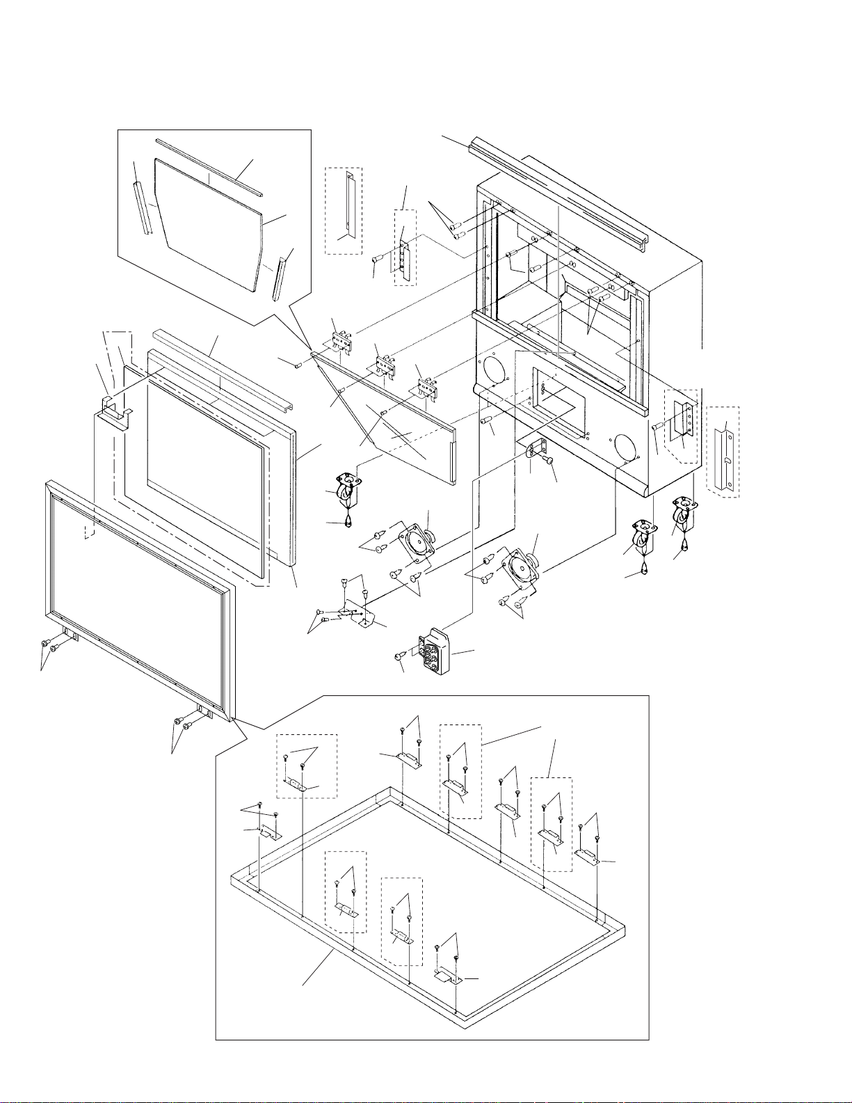
2.4 REAR VIEW (1/2)
10
3
2
2
2
9
2
2
2
5
5
5
8
1
10
3
2
2
8
4
8
13
7
2
9
7
8
2
12
2
2
9
2
PRO-610HD, PRO-510HD Only
11
13
12
PRO-610HD, PRO-510HD, SD-582HD5, SD-532HD5
(1) REAR VIEW (1/2) PARTS LIST
Mark No. Description Part No.
1 Mirror Case 51 AME2296
2 Screw ABA1240
3 Screw PYC40T140FZB
4 Rear Cover AMM2999
5 Blind Sheet AEC1622
6 .................................
7 Screw ABZ30P100FZK
NSP 9 Cabinet Wire Holder AEC1263
8 Screw ABA1269
10 Screen Cushion
See Contrast table (2)
11 Rear Cover (DTV)
12 Rear Cover Sheet
13 Screw PMB40P250FZB
See Contrast table (2)
See Contrast table (2)
(2) CONTRAST TABLE
PRO-610HD, PRO-510HD, SD-582HD5 and SD-532HD5 are constructed the same except for the following:
Mark Remarks
Symbol and DescriptionNo.
PRO-610HD PRO-510HD SD-582HD5 SD-532HD5
10 Screen Cushion AEC1830 AEC1831 AEC1845 AEC1844
11 Rear Cover (DTV) AMM3000 AMM3000 Not used Not used
12 Rear Cover Sheet AMR3190 AMR3190 Not used Not used
Part No.
13
PRO-610HD, PRO-510HD, SD-582HD5, SD-532HD5
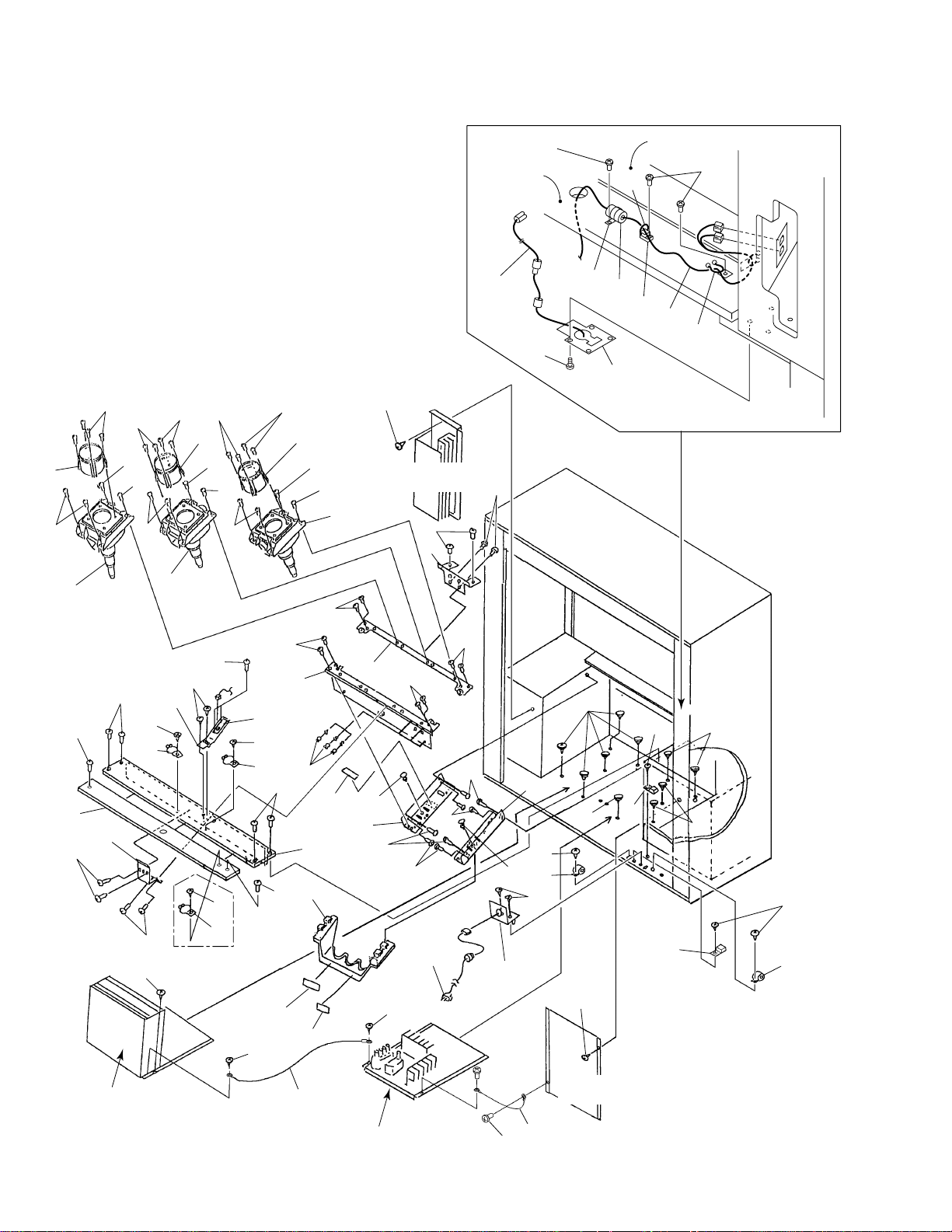
2.5 REAR VIEW (2/2)
7
7
4
6
5
7
7
4
5
6
6
6
6
PRO-610HD, PRO-510HD Only
13
Rear Cover
Panel
37
44
7
4
5
6
38
Refer to "2.10 CONV.
AMP BLOCK".
3
10
13
11
41
Back Cover Panel
39
42
40
32
36
24
35
22
13
39
24
10
38
2
38
25
26
24
PRO-610HD,
PRO-510HD
Only
39
38
27
39
24
29
23
23
10
9
14
30
21
28
10
15
17
16
10
8
10
20
20
20
13
33
19
38
13
34
13
19
31
16
18
13
13
33
38
20
13
32
32
1
23
23
12
Refer to "2.7 VIDEO
BLOCK".
14
43
Refer to "2.8 DEFLECTION
BLOCK".
Refer to "2.9 POWER
SUPPLY BLOCK".
43
38
PRO-610HD, PRO-510HD, SD-582HD5, SD-532HD5
(1) REAR VIEW (2/2) PARTS LIST
Mark No. Description Part No. Mark No. Description Part No.
1 CRT Service Assy B
2 CRT Service Assy G
3 CRT Service Assy R
4 Lens Assy
5 Screw FBT40P120FZK
6 Screw ABA1168
7 Screw AMZ40P080FZK
NSP 8 CRT Front Frame
NSP 9 CRT Rear Frame
10 Screw ACZ40P080FMC
NSP 11 CRT Front Holder ANG2118
NSP 12 CRT Rear Holder ANG2119
13 Screw ABA1240
14 Cord Holder AEC1257
NSP 15 Tube Label AAX2497
16 Rivet AEC-441
NSP 17 CRT Stand Holder R ANA1497
NSP 18 CRT Stand Holder L ANA1496
19 Screw PMB50P250FZB
20 Special Screw ABA1121
NSP 21 Back Cover Panel
22 Rear Cover Panel AMM3010
23 Screw ABA1241
NSP 24 Cabinet Wire Holder AEC1263
25 Screw ABA1279
See Contrast table (2)
See Contrast table (2)
See Contrast table (2)
See Contrast table (2)
See Contrast table (2)
See Contrast table (2)
See Contrast table (2)
NSP 31 AC Cord Holder A ANG2307
NSP 32 Bind Holder AEC1785
33 Ferrite Core ATX1033
34 AC Power Cord ADG1180
NSP 35 AC Cord Holder B
36 Wire Harness C (J14)
37 AC Power Cord
38 Screw BBZ30P080FZK
39 Screw ABA1271
40 Ferrite Core
NSP 41 Nylon Clamp 18N AEC1789
42 Nylon Binder AEC-093
43 1P Lead Wire (J1) ADX2505
44 Screw PMB40P250FZB
See Contrast table (2)
See Contrast table (2)
See Contrast table (2)
See Contrast table (2)
NSP 26 Fixing Metal ANG1958
27 SR Assy AWZ6465
NSP 28 Tray AMR2563
NSP 29 Solder Warning Label AAX2672
NSP 30 Warning Label (KC) AAX1797
(2) CONTRAST TABLE
PRO-610HD, PRO-510HD, SD-582HD5 and SD-532HD5 are constructed the same except for the following:
Mark Remarks
Symbol and DescriptionNo.
PRO-610HD PRO-510HD SD-582HD5 SD-532HD5
1 CRT Service Assy B AWY1422 AWY1418 AWY1420 AWY1418
2 CRT Service Assy G AWY1413 AWY1417 AWY1417 AWY1417
3 CRT Service Assy R AWY1421 AWY1416 AWY1419 AWY1416
4 Lens Assy AMR3183 AMR2833 AMR2833 AMR2833
NSP 8 CRT Front Frame ANA1613 ANA1614 ANA1613 ANA1614
NSP 9 CRT Rear Frame ANA1615 ANA1616 ANA1615 ANA1616
NSP 21 Back Cover Panel AMM3001 AMM3002 AMM3001 AMM3002
NSP 35 AC Cord Holder B ANG2311 ANG2311 Not used Not used
36 Wire Harness C (J14) ADX2491 ADX2491 Not used Not used
37 AC Power Cord ADG1185 ADG1185 Not used Not used
40 Ferrite Core (L9) ATX1031 ATX1031 Not used Not used
Part No.
15
PRO-610HD, PRO-510HD, SD-582HD5, SD-532HD5
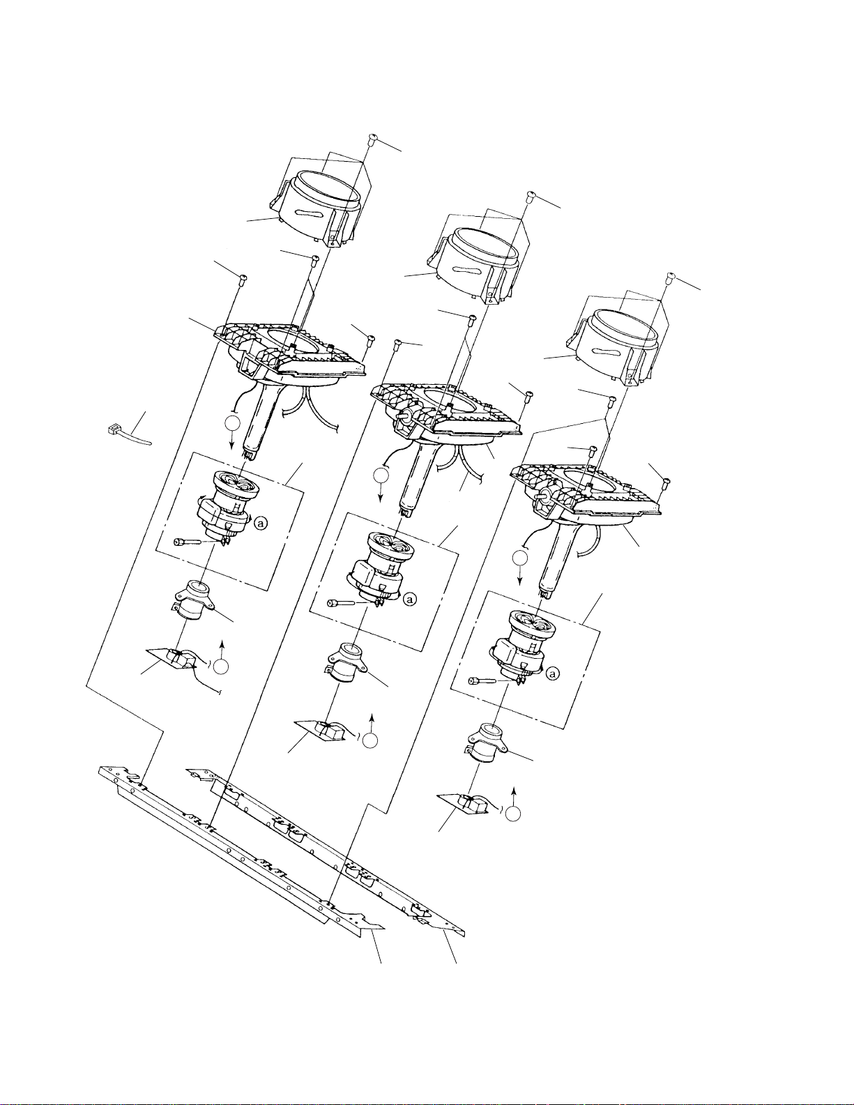
2.6 CRT BLOCK
5
20
1
7
2
7
1
6
7
7
6
5
5
1
7
A
9
B
Anode Cable
3
10
7
C
6
4
11
15
12
A
13
B
16
14
C
17
19
18
16
PRO-610HD, PRO-510HD, SD-582HD5, SD-532HD5
(1) CRT BLOCK PARTS LIST
Mark No. Description Part No.
1 Lens Assy
2 CRT Service Assy R
3 CRT Service Assy G
4 CRT Service Assy B
5 Screw AMZ40P080FZK
6 Screw FBT40P120FZK
7 Screw ABA1168
8 ...........
9 Deflection Yoke (L1) ATL1136
10 Deflection Yoke (L2) ATL1136
11 Deflection Yoke (L3) ATL1136
12 VM Coil (L4) ATL1137
13 VM Coil (L5) ATL1137
14 VM Coil (L6) ATL1137
15 R. CRT DRIVE Assy AWZ6457
16 G. CRT DRIVE Assy AWZ6458
17 B. CRT DRIVE Assy AWZ6459
NSP 18 CRT Rear Frame
NSP 19 CRT Front Frame
20 Nylon Binder AEC-093
See Contrast table (2)
See Contrast table (2)
See Contrast table (2)
See Contrast table (2)
See Contrast table (2)
See Contrast table (2)
(2) CONTRAST TABLE
PRO-610HD, PRO-510HD, SD-582HD5 and SD-532HD5 are constructed the same except for the following:
Mark Remarks
Symbol and DescriptionNo.
PRO-610HD PRO-510HD SD-582HD5 SD-532HD5
1 Lens Assy AMR3183 AMR2833 AMR2833 AMR2833
2 CRT Service Assy R AWY1421 AWY1416 AWY1419 AWY1416
3 CRT Service Assy G AWY1413 AWY1417 AWY1417 AWY1417
4 CRT Service Assy B AWY1422 AWY1418 AWY1420 AWY1418
NSP 18 CRT Rear Frame ANA1615 ANA1616 ANA1615 ANA1616
NSP 19 CRT Front Frame ANA1613 ANA1614 ANA1613 ANA1614
Part No.
17
PRO-610HD, PRO-510HD, SD-582HD5, SD-532HD5
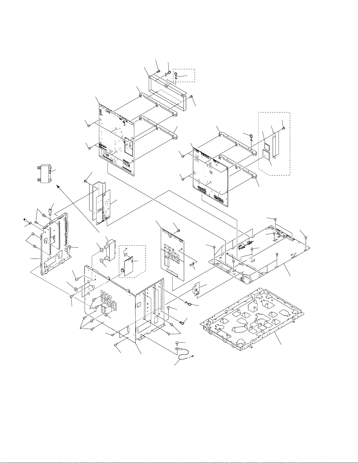
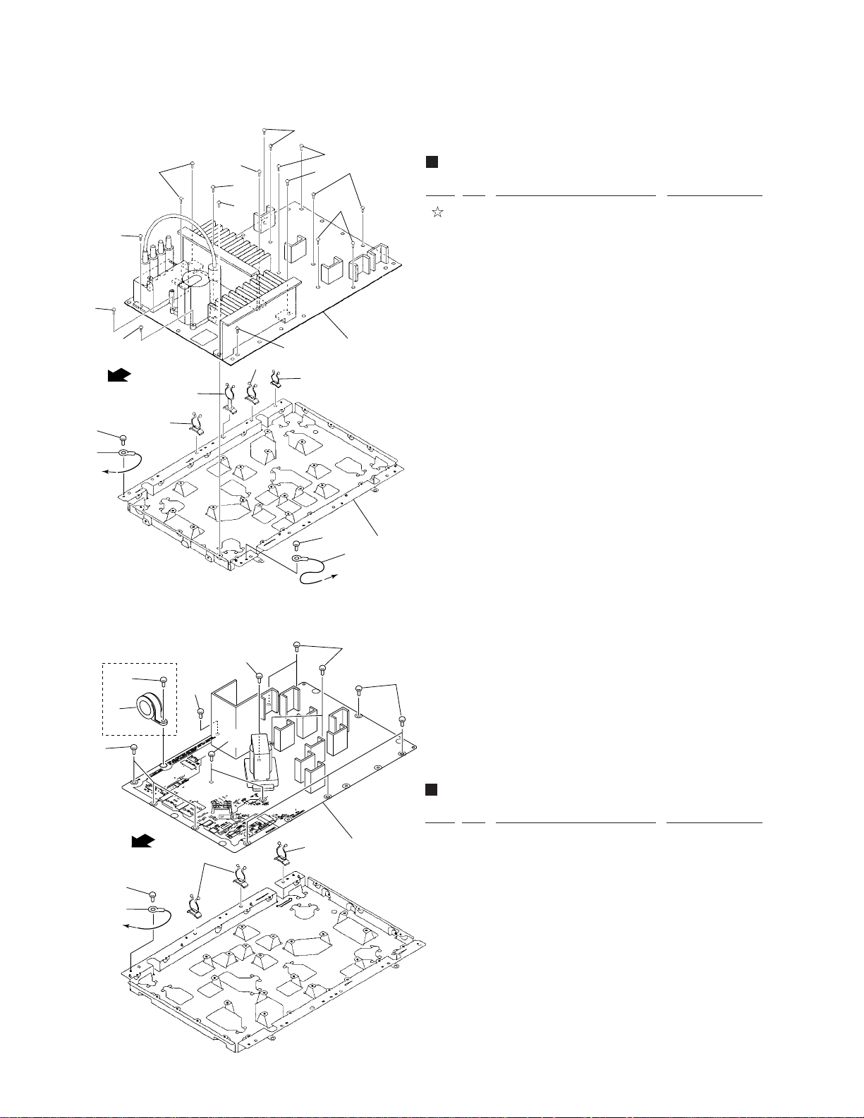
2.7 VIDEO BLOCK
12
13
PRO-610HD,
PRO-510HD
14
Only
3
10
15
4
4
∗
No.24: RF Switch
Top
Bottom
23
3
Connector
11
10
9
4
4
19
30
10
14
18
16
10
19
17
PRO-610HD,
PRO-510HD
Only
22
5
PRO-610HD,
∗
3
3
21
3
28
3
3
3∗: PRO-610HD,
PRO-510HD
Only
24
25
3
8
25
3∗
PRO-510HD
Only
26
3
7
31
3
3
4
29
6
3
3
14
20
3
To DEFLECTION
BLOCK
3
3
4
4
3
2
1
18
PRO-610HD, PRO-510HD, SD-582HD5, SD-532HD5
(1) VIDEO BLOCK PARTS LIST
Mark No. Description Part No. Mark No. Description Part No.
NSP 1 Video Chassis ANA1584
NSP 10 PCB Sub Frame ANG2304
NSP 13 Cable Clip D3S AEC1782
NSP 16 IP Heat Sink S
NSP 17 IP Heat Sink M
NSP 20 Cable Clip D3M AEC1783
NSP 22 Lead Clamper M AEC1611
NSP 23 Cable Clip A AEC1325
2 VIDEO Assy
3 Screw BBZ30P080FZK
4 Screw BBZ30P080FCU
5 AV I/O Assy
6 RGB SW Assy AWZ6468
7 Rear Panel
8 Hexagon Head Screw BBA1051
9 SIGNAL Assy
11 Signal Shield ANK1629
12 Rivet AEC–441
14 Cable Clip AEC1806
15 SUB VIDEO Service Assy
18 IP Heat Sink Holder
19 Screw
21 PCB Side Holder ANG2305
24 RF Switch AXF1088
25 Washer WAXOF160N100
See Contrast table (2)
See Contrast table (2)
See Contrast table (2)
See Contrast table (2)
See Contrast table (2)
See Contrast table (2)
See Contrast table (2)
See Contrast table (2)
See Contrast table (2)
26 BNC Assy
27 Screw
28 Nut BBN1005
NSP 29 Mini Card Spacer AEC1835
30 AUDIO Assy
31 1P Laed Wire ADX2505
See Contrast table (2)
See Contrast table (2)
See Contrast table (2)
(2) CONTRAST TABLE
PRO-610HD, PRO-510HD, SD-582HD5 and SD-532HD5 are constructed the same except for the following:
Mark Remarks
Symbol and DescriptionNo.
PRO-610HD PRO-510HD SD-582HD5 SD-532HD5
2 VIDEO Assy AWV1799 AWV1799 AWV1804 AWV1804
5 AV I/O Assy AWV1802 AWV1802 AWV1807 AWV1807
7 Rear Panel ANC2336 ANC2336 ANC2337 ANC2337
9 SIGNAL Assy AWV1800 AWV1800 AWV1805 AWV1805
15 SUB VIDEO Service Assy AWV1819 AWV1819 Not used Not used
15 SUB VIDEO Assy Not used Not used AWV1806 AWV1806
NSP 16 IP Heat Sink S ANH1572 ANH1572 Not used Not used
NSP 17 IP Heat Sink M ANH1571 ANH1571 Not used Not used
18 IP Heat Sink Holder AEC1850 AEC1850 Not used Not used
26 BNC Assy AWZ6464 AWZ6464 Not used Not used
27 Screw
30 AUDIO Assy AWZ6472 AWZ6472 AWZ6469 AWZ6469
BCZ30P080FZK BCZ30P080FZK
Part No.
Not used Not used
19
PRO-610HD, PRO-510HD, SD-582HD5, SD-532HD5
2.8 DEFLECTION BLOCK
2
3
4
3
2
6
Rear Side
To VIDEO
BLOCK
3
3
4
4
7
2
9
6
2.9 POWER SUPPLY BLOCK
5
2
3
2
2
To POWER
SUPPLY
BLOCK
2
DEFLECTION BLOCK PARTS LIST
Mark No. Description Part No.
1 DEFLECTION SERVICE AWV1809
Assy
2 Screw BBZ30P080FZK
3 Screw ABZ30P100FZK
NSP 5 Cable Clip D3S AEC1782
NSP 6 Cable Clip D3M AEC1783
NSP 7 Cable CliP AEC1325
1
8
9
NSP 8 DF Chassis ANA1583
4 Screw VBZ30P200FMC
9 1P Laed Wire ADX2505
PRO-610HD,
PRO-510HD Only
2
Bottom Side
To DEFLECTION
BLOCK
2?
6
5
2
2
2
2
POWER SUPPLY BLOCK PARTS LIST
Mark No. Description Part No.
3
2
4
3
1
NSP 3 Cable Clip D3M AEC1783
1 POWER SUPPLY Assy AWV1795
(for PRO-610HD, PRO-510HD)
1 POWER SUPPLY Assy AWV1808
(for SD-582HD5, SD-532HD5)
2 Screw BBZ30P080FZK
4 1P Laed Wire ADX2505
5 Ferrite Core ATX1033
(PRO-610HD, PRO-510HD only)
6 Screw ABZ30P100FZK
(PRO-610HD, PRO-510HD only)
20

2.10 CONV. AMP BLOCK
PRO-610HD, PRO-510HD, SD-582HD5, SD-532HD5
3
3
CONV. AMP BLOCK PARTS LIST
Mark No. Description Part No.
3
6
4
3
3
7
8
3
9
6
NSP 2 CONV. Chassis ANA1619
5
NSP 6 CONV. Holder ANG2365
NSP 7 Cable Clip D3M AEC1783
NSP 8 Cable Clip D3S AEC1782
1
2
1 CONV. AMP Assy AWZ6456
3 Screw ABZ30P100FMC
4 CONNECTOR Assy AWZ6461
5 DIGITAL CONV. ASSY AWZ6460
9 Cable Clip AEC1806
3
21
1
23
PRO-610HD, PRO-510HD, SD-582HD5, SD-532HD5
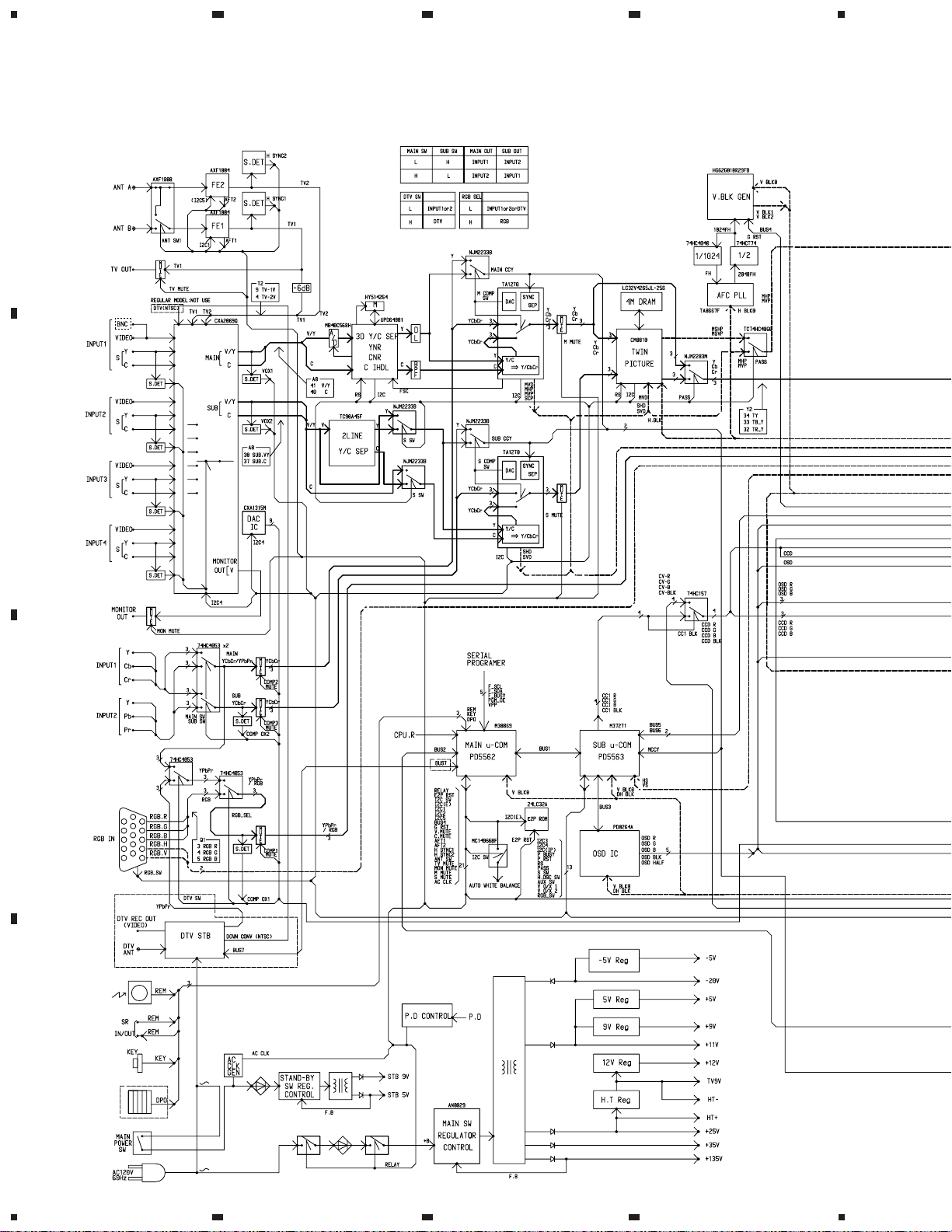
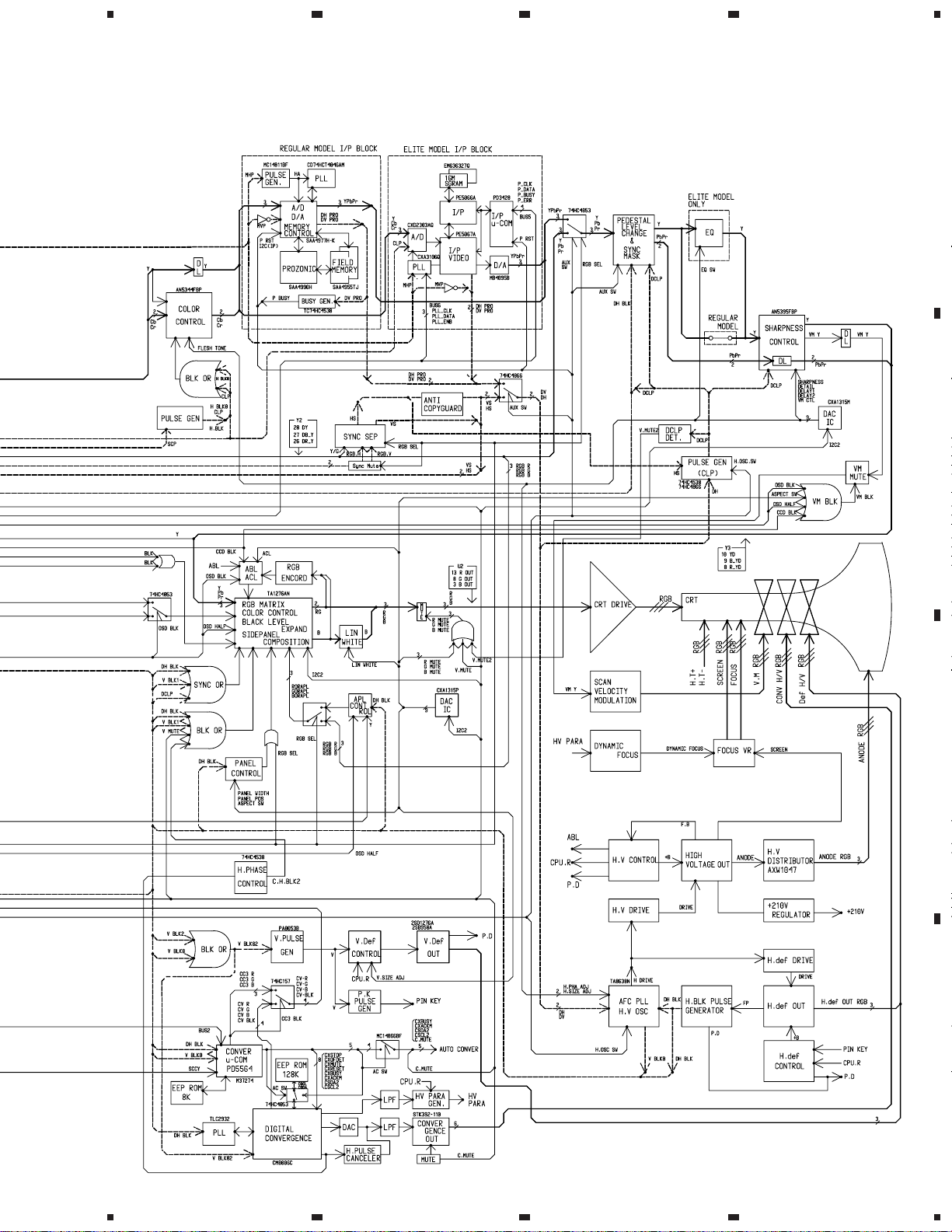
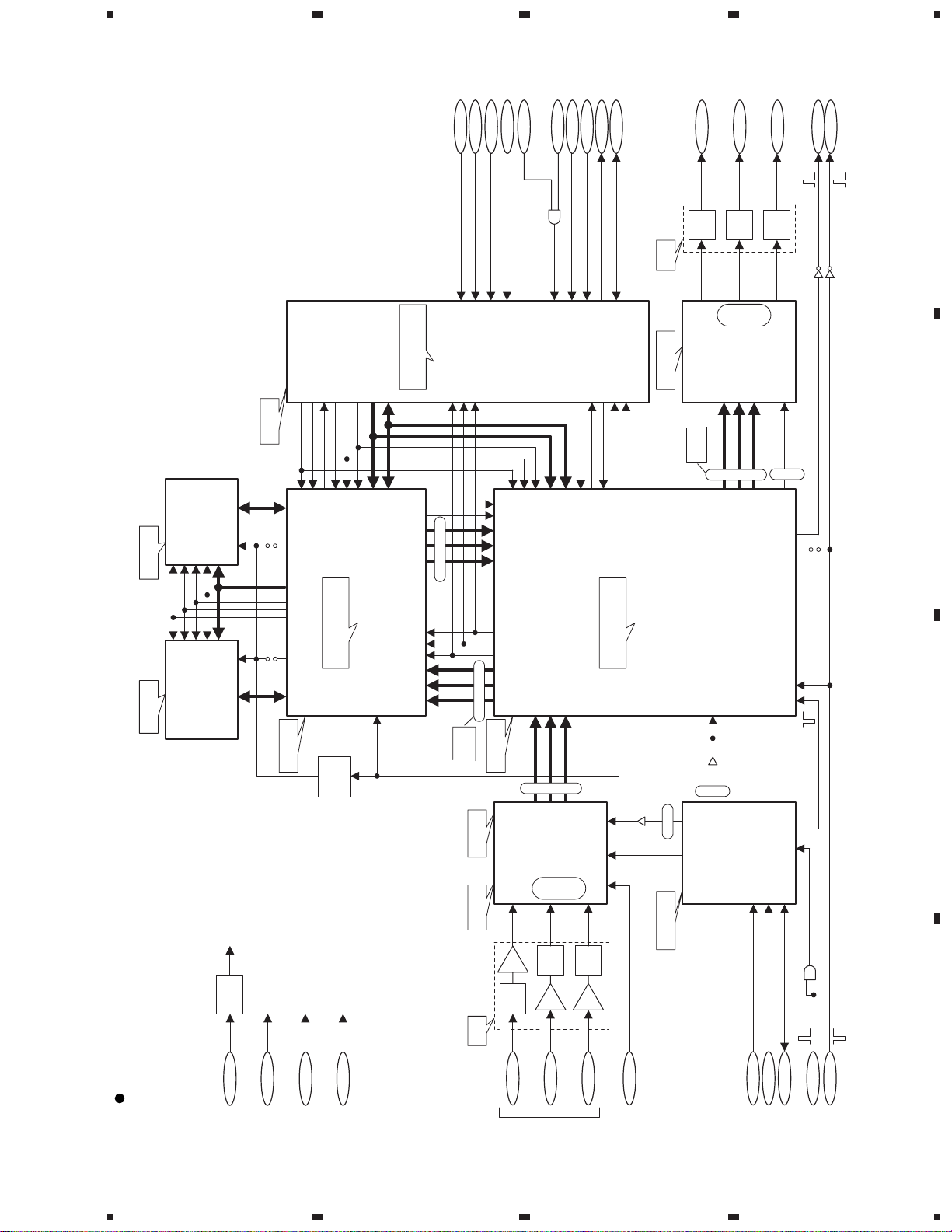
3. BLOCK DIAGRAM AND SCHEMATIC DIAGRAM
3.1 BLOCK DIAGRAM
3.1.1 OVERALL BLOCK DIAGRAM
A
ELITE
MODEL
Only
B
4
C
ELITE MODEL ONLY
D
22
1234
5
678
PRO-610HD5, PRO-510HD5, SD-582HD5, SD-532HD5
Note : Model names indicated by "ELITE" and "REGULAR" are as follows:
ELITE : PRO-610HD and PRO-510HD, REGULAR : SD-582HD5 and SD-532HD5
A
B
C
D
23
5
6
7
8
1
23
PRO-610HD, PRO-510HD, SD-582HD5, SD-532HD5
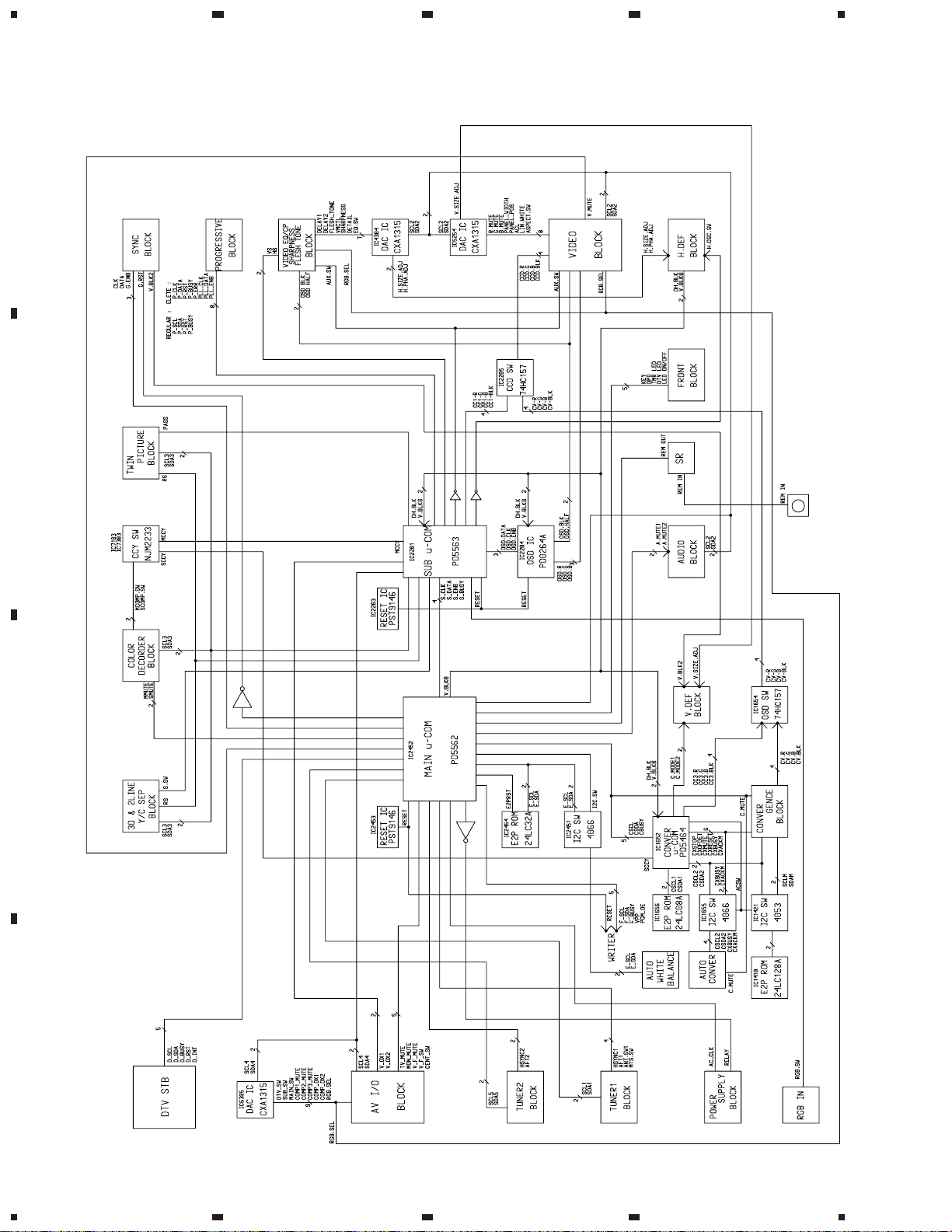
3.1.2 CONTROL BLOCK
A
B
4
C
D
24
1234
1
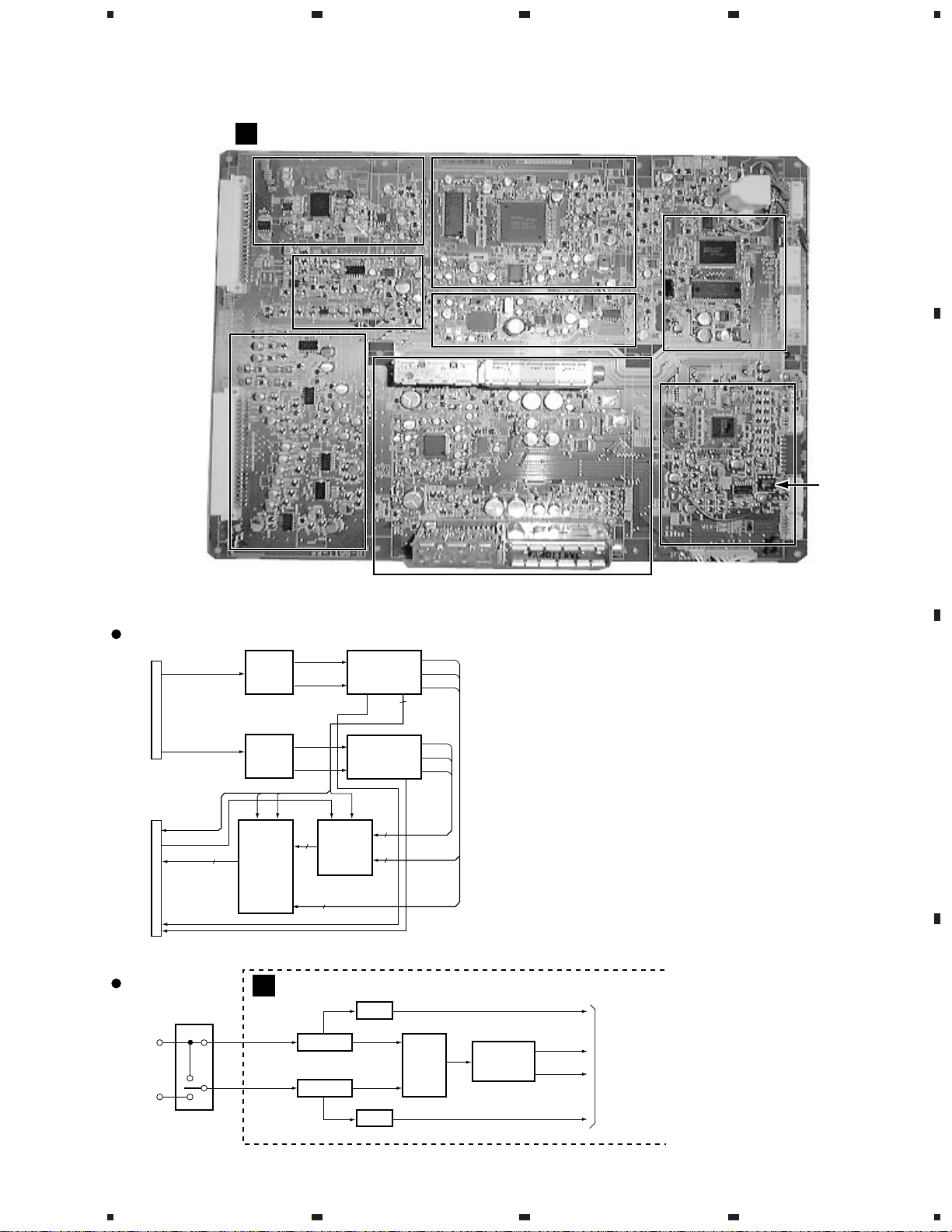
3.1.3 SIGNAL BLOCK
A
SIGNAL ASSY
AV I/O
AV I/O
Component
Component
Block
Block
PRO-610HD5, PRO-510HD5, SD-582HD5, SD-532HD5
Sub-color
Sub-color
Demodulation
Demodulation
Block
Block
2 Line Y/C
2 Line Y/C
Block
Block
234
A
Twin Picture BlockTwin Picture Block
3D Y/C Sep.
3D Y/C Sep.
Block
Block
Main-color
Main-color
Demodulation Block
Demodulation Block
FE2FE2
Main
Tuner Block
Tuner Block
Main
Microcomputer
Microcomputer
Block
Block
IC2454
B
EEPROM
Video Block
SUB. VY
CN2454
H. BLK
SCP0
TY
TB-Y
TR-Y
MHP
MVP
CN7501
Tuner Block
RF SW
AXF1088
ANT A
ANT B
VY
5
3D Y/C
Sep.
BLock
SUB.Y
2L Y/C
Sep.
SUB.C
BLock
MVDMHD
Single-
screen
or
B-Y
Sprit-
screens
SW Block
R-Y
A
SIGNAL ASSY
Tuner 1
5
Y
H
V
Y
C
FE2
FE1
Main-color
Demodulation
BLock
MCCY
Sub-color
Demodulation
BLock
TWIN-P
Block
3
MCCY
SCCY
MVD
AMP
AudioTuner 2
Audio
AMP
FE1
FE1
MY
MB-Y
MR-Y
MHD
3
MVD
SCP0
SY
SB-Y
SR-Y
3
3
Note :
Main picture is able to receive the
ANT A and B.
Sub picuture is able to receive the
ANT A only.
MTS
SW
IC2702
TV2-V (1Vp-p)
MTS
DECODER
IC2701
TV1-V (1Vp-p)
TV-L
TV-R
To
AV I/O Block
C
D
25
1
2
3
4
1
23
PRO-610HD, PRO-510HD, SD-582HD5, SD-532HD5
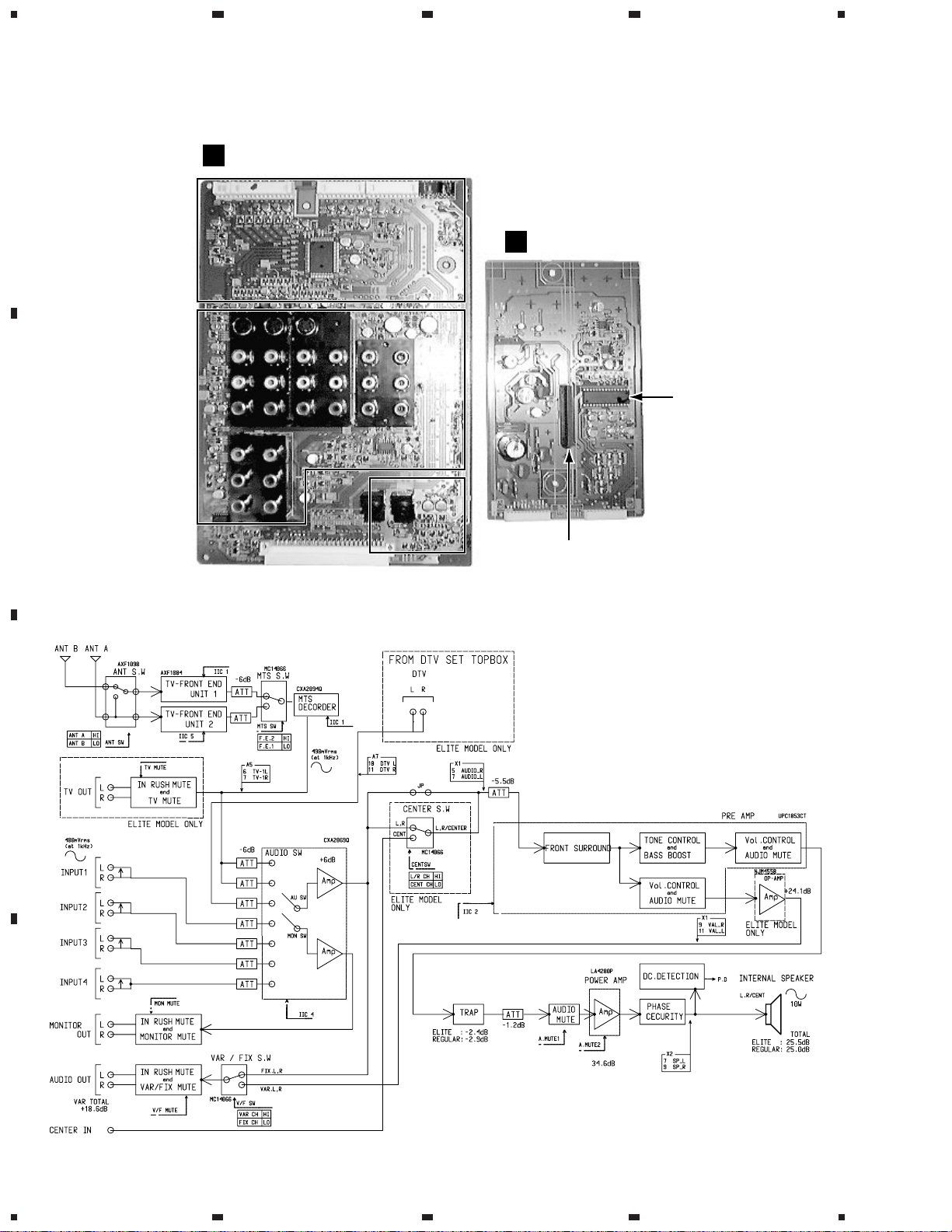
3.1.4 AV I/O and AUDIO ASSYS
B
A
B
AV I/O ASSY
Selector Block
Selector Block
Pin Jack Block
Pin Jack Block
G
AUDIO ASSY
4
NOTE) The AUDIO Assy show the state
without the heat sink.
Please attach the heat sink when
you install the AUDIO Assy.
PRE AMP IC
IC1201
SR Block
SR Block
POWER AMP IC
IC1202
C
D
26
1234
1
234
PRO-610HD5, PRO-510HD5, SD-582HD5, SD-532HD5
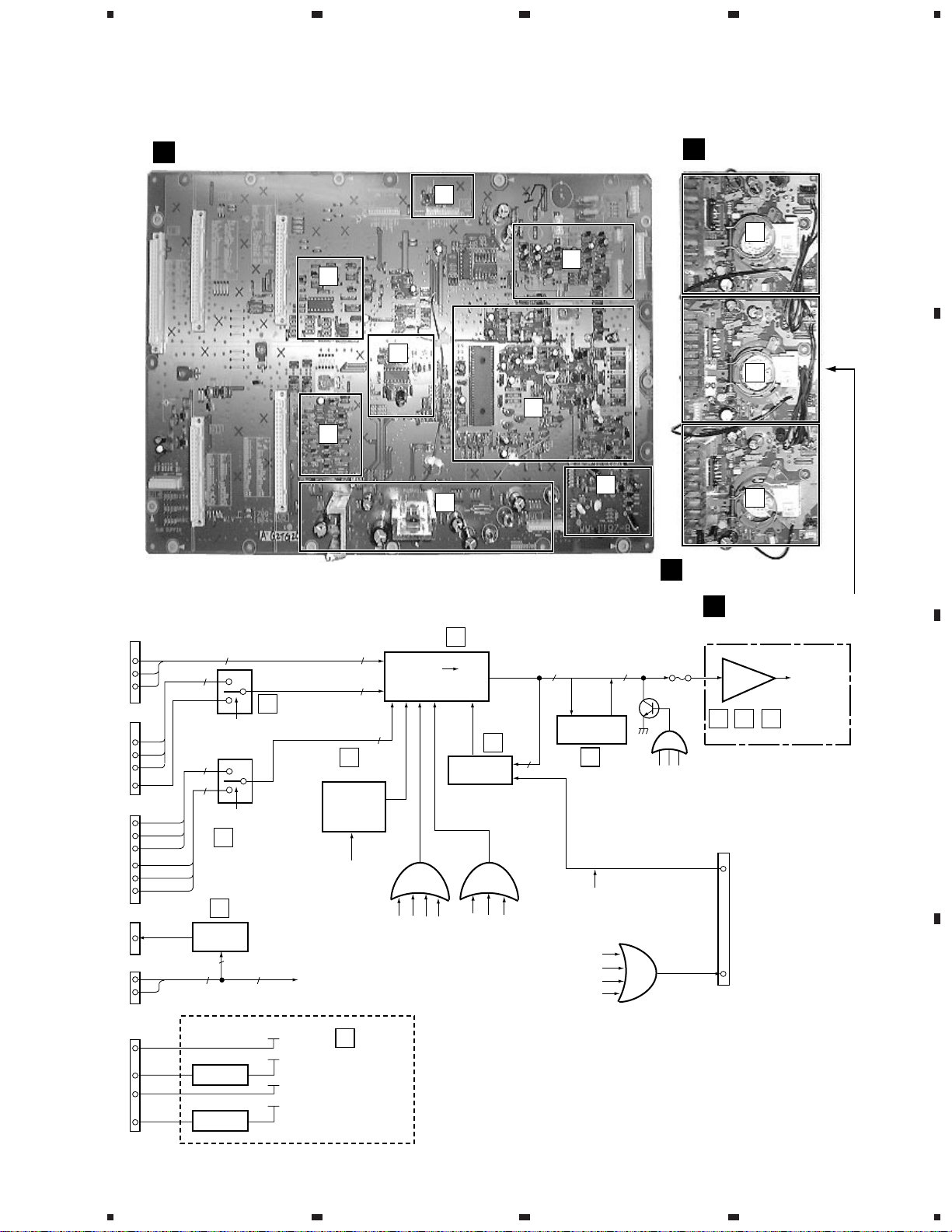
3.1.5 VIDEO, R, G and B CRT DRIVE ASSYS
E
VIDEO ASSY
F
G
E
H
D
M
R CRT DRIVE ASSY
A
I
B
J
A
B
C
K
CN5602
8
9
10
CN5604
26
27
28
10
CN5602
18
19
41
22
43
44
CN5610
6
CN5607
7
9
PD
Y, Pb, Pr
R,G,B
APL
DH.BLK
OSD
CCD
SP. LR
3
3
RGB SEL
IC5256
3
3
OSD BLK1
G
F
Audio PD
Block
2
2
H
RGB Selector
Block
OSD SW
Block
SP. LR
2
E
IC5252
Panel BLK
Generation
Block for
4:3 Size
DH. BLK
Aspect SW
Panel POS
Panel Width
(SP)
IC5251
3
Y color
Difference
3
Conversion Block
3
BLK
DH.BLK
or
V BLK1
V MUTE
A
RGB
ABL & ACL
Block
SYNC
DH.BLK
C.H.BLK2
B
or
V BLK1
R
G
B
3
D CLP
ASPECT SW
RGB
3
BB
Linear White
Block
C
CCD BLK
OSD BLK
ACL
OSD BLK
CCD BLK
OSD HALF
3
VM
BLK
or
O
B CRT DRIVE ASSY
N
G CRT DRIVE ASSY
CRT
AMP
I J K
OR
V. MUTE
V. MUTE2
RGB MUTE
CN5602
ABL
5
VM BLK
20
Cathode
C
CN5608
IC5602
9V Reg.
IC5601
3.3V Reg.
1
12.4V
9V
5V
3.3V
D
Regulator
Block
D
27
2
3
4
1
23
PRO-610HD, PRO-510HD, SD-582HD5, SD-532HD5
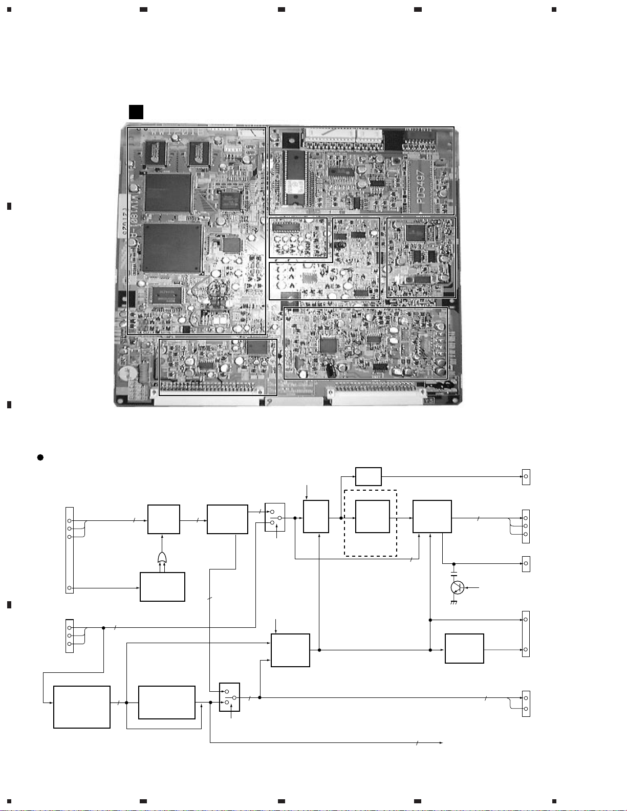
3.1.6 SUB VIDEO ASSY
4
A
H
SUB VIDEO ASSY (ELITE)
I/P Block
I/P Block
Note : SUB VIDEO ASSY of the REGULAR model is the same as that of
the ELITE model excepting I/P Block.
Sub-microcomputer
Sub-microcomputer
Block
Block
Double Speed
Double Speed
Sync. Sep.
Sync. Sep.
Block
Block
Clamp Pulse &
Clamp Pulse &
Copy Guard Canceller
Copy Guard Canceller
Block
Block
Zoom
Zoom
V Scroll
V Scroll
Block
Block
B
Sharpness Block
Sharpness Block
Fresh Tone Block
Fresh Tone Block
Sub Video Block
Y
APL
DH,BLK
Y
IC4051
HD
DH
DV
DH
2
Pb
Pr
AUX SW
RGB SEL
H.OSC.SW2
Clamp
Pulse
Generator
Block
IC3001
Y
Pb
Pr
3
VD
HD
Y
Cb
Cr
2
Fresh
3
Tone
BLock
SCP
H. Block
Clamp Pulse
Generation
IC3003
IC4054
Copy Guard
HD
Cancel Block of
External Double
Speed Signal
C
D
CN3002
32
33
34
10
CN3002
26
27
28
G or Y
IC4052
SYNC SEP.
Block of
External Double
Speed input
Signal
VD
Y
Cb
I/P
33
Cr
Conversion
BLock
Refer to
I/P System
Block.
VD
2
HD
IC4053
SYNC SW NTSC
SYNC SW HD
Y
IC4056
IC4055
SYNC
Mask
Block
CP
Block
IC4001
EQ
Y
Block
(EQ SW)
ELITE
ONLY
IC4301
Sharpness
Y
VM
Block
Pb
Pr
2
HS
VS
2
CP
CPCP
APL
Y
Pb
Pr
3
VM-Y
VM. BLK
V.MUTE2
Generator
Block
DH
DV
(To Sub-microcomputer)
CP
V.MUTE2
2
CN3002
1
CN3001
8
9
10
CN2201
2
CN3001
36
11
CN2201
4
6
28
1234
1
234
PRO-610HD5, PRO-510HD5, SD-582HD5, SD-532HD5
16M SGRAM
CS
3.3V (65mA)
CS
3.3V (65mA)
16M SGRAM
IC3604
QFP 128P
EM636327Q-8
RAS
CASWEA[0-10]
WE
RAS
CAS
A[0-10]
IC3601
QFP 128P
EM636327Q-8
Dc[0-31]
CLKc
CLKy
Dy[0-31]
5V(55mA)
Dc[0-31]
CLKc
CLKy
Dy[0-31]
CSi
Reset
Film
I/P kill
CSi
Film
Reset
I/P kill
A[0-10]
WE
CAS
RAS
CS
Operating frequency
HWR
RD
RD
HWR
I/P
: 56MHz
D[0-7]
Au[0-11]
D[0-7]
Au[0-11]
IC3401
PE5066A
QFP 240P
CLKip
MD2
MD2
: 20MHz
I/P 16bit U-COM
Vp
Hp
PRp[0-15]
PBp[0-15]
Yp[0-15]
14MHz Parallel
Fi
Vi
Hi
PRi[0-7]
PBi[0-7]
Yi[0-7]
QFP 100P
HD64FR3067
HiViFi
Operating frequency
TXD
RXD
FWE
TXD
RXD
FWE
IC3801
Vp
Hp
Fi
Vi
Hi
14MHz Single
RESET
RD
Reset
Yi[0-7]
Yp[0-15]
PRi[0-7]
PBi[0-7]
P_RST
TC7SET08FU
P_RST
HWR
Au[0-11]
PRp[0-15]
PBp[0-15]
Yad[0-7]
PBad[0-7]
PRad[0-7]
P_DATA
P_DATA
D[0-7]
P_CLK
P_CLK
CSv
CSv
WAIT
WAIT
P_ERR
P_BUSY
5V
P_ERR
P_BUSY
Fdetect
Fdetect
: 56MHz
5VReg(80mA)
PE5067A
QFP 304P
I/P VIDEO
SGLB
Vactive
SGLB
Vactive
Operating frequency
D/A
14MHz
IC3501
DY1
0.69Vpp
L.P.F
12MHz
1.38Vpp
QFP 48P
MB40958
multiplex
DB-Y1
0.77Vpp
12MHz
1.54Vpp
IC3602
Yda[0-7]
PBda[0-7]
Yda[0-7]
PBda[0-7]
L.P.F
2Vp-p input
Full scale
PRda[0-7]
28MHz Single
PRda[0-7]
DR-Y1
0.77Vpp
L.P.F
12MHz
1.54Vpp
CLKda
CLKda
TC7SET04FU
28MHz
HSYNCp
VSYNCp
VSYNCi
IPHS
DV PRO
DH PRO
A
TC7SET04FU
B
160mA
IC3206
5V Reg
TA78M05F
I/P System Block (ELITE)
30mA
9V
11V
1
3.3V(850mA)
150mA
5V
CLK
Delay
: 56MHz
1.7A
3.3V
Branch
process
3.3V(700mA)
3.3V(5mA)9V
A/D
5V(70mA)
IC3203
QFP 80P
CXD2303AQ
1.44Vpp
AMP
L.P.F
5MHz
1.44Vpp
Y2
Yad[0-7]
PBad[0-7]
1.44Vpp
L.P.F
5MHz
AMP
1.0Vpp
B-Y2
Input Signal
100/0/100/0
28MHz Single
PRad[0-7]
2Vp-p input
Full scale
1.44Vpp
5MHz
AMP
1.0Vpp
R-Y2
Color Bar
L.P.F
CLKad
SY
CLP
TC74LCX541FT
CLP
CLKad
28MHz
SY
5VReg(70mA)
TC74LCX541FT
56MHz
CLKip CLKip
PLL
IC3201
QFP 48P
CXA3106Q
PLL_ENB
PLL_CLK
PLL_ENB
PLL_CLK
IPHS
HSYNCi
PLL_DATA
TC7SET08FU
PLL_DATA
MHP
MVP
C
D
29
2
3
4

1
23
PRO-610HD, PRO-510HD, SD-582HD5, SD-532HD5
I/P System Block (REGULAR)
A
IC3404
DELAY
MC14011BF
MHP
MVP
Active :Hi
Active :Low
4
IC3402
PLL
CD74HCT4046AM
HRD
32MHz
0.68Vp-p 0.89Vp-p
DV1
DB_Y1
DR_Y1
Input Signal
100/0/100/0
B
Color Bar
0.86Vp-p 0.77Vp-p
0.85Vp-p 0.74Vp-p
1.38Vp-p 0.38Vp-p
Y2
1.0Vp-p 0.82Vp-p
B-Y2
1.0Vp-p 0.625Vp-p
R-Y2
AMP & LPF
AMP & LPF
AMP & LPF
ATT
ATT
ATT
VACQ HA LLD
D/A CONV.
Yid(0-7)
Uvid(4-7)
IC3403
BESIC
SAA4977H
A/D CONV.
Yod(0-7)
UVod(4-7)
SWC
16MHz
12
IC3401
PROZONIC
SAA4990H
YD(0-7)
UVD(0-3)
12
IC3406
Field Memory
SAA4995TJ
SWCK
12
YA(0-7)
UVA(0-3)
Double
speed
Q0-Q11
D0-D11
Normal
speed
CLK
YB(0-7)
UVB(0-3)
YC(0-7)
UVC(0-3)
SRCK
Double
speed
Double
speed
12
12
SWCK/SRCK
IC3405
Field Memory
SAA4995TJ
Q0-Q11
D0-D11
C
D
30
1234
 Loading...