

Pioneer PRO-510HD User Manual
PROJECTION MONITOR RECEIVER
PRO-610HD
PRO-510HD
SD-582HD5
SD-532HD5
THIS MANUAL IS APPLICABLE TO THE FOLLOWING MODEL(S) AND TYPE(S).
ORDER NO.
ARP3051
Type
PRO-610HDPRO-510HD SD-582HD5 SD-532HD5
KUXC/CA AC120V
KBXC –– –– –– AC120V
This service manual should be used together with the following manual(s):
Model No.
PRO-610HD
Model
ARP3047
Power Requirement
RemarksOrder No.
Remarks
CONTENTS
6. ADJUSTMENT................................................195
7. GENERAL INFORMATION ............................ 219
7.1 DIAGNOSIS..............................................219
7.1.1 DIAGNOSIS METHOD....................219
7.1.2 DISASSEMBLY ...............................224
7.1.3 WIRING DIAGRAM ......................... 226
PIONEER CORPORATION 4-1, Meguro 1-Chome, Meguro-ku, Tokyo 153-8654, Japan
PIONEER ELECTRONICS SERVICE, INC. P.O. Box 1760, Long Beach, CA 90801-1760, U.S.A.
PIONEER ELECTRONIC (EUROPE) N.V. Haven 1087, Keetberglaan 1, 9120 Melsele, Belgium
PIONEER ELECTRONICS ASIACENTRE PTE. LTD. 253 Alexandra Road, #04-01, Singapore 159936
PIONEER CORPORATION 1999
7.2 IC .............................................................. 228
7.3 EXPLANATION.........................................254
8. PANEL FACILITIES AND SPECIFICATIONS
..............................................................266
O–ZZR NOV. 1999 Printed in Japan

PRO-610HD, PRO-510HD, SD-582HD5, SD-532HD5
194

PRO-610HD, PRO-510HD, SD-582HD5, SD-532HD5
6. ADJUSTMENT
6.1 INTRODUCTION
• IMPORTANT
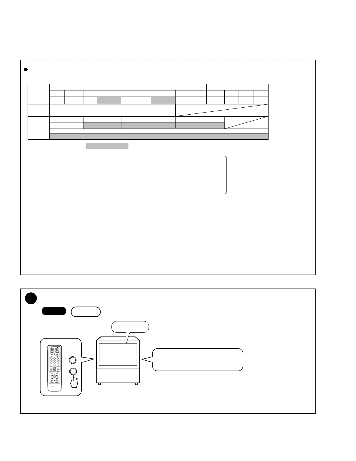
When replacement of the following assemblies are required during repairs, be sure to replace the EEPROMs with the mounted ones in order to
retain the adjustment data of the unit and to facilitate adjustment after the replacement of the assemblies.
Name of Assy EEPROM Main Contents of Memory
SIGNAL Assy IC2454 [24LC32(I)P] Adjustment data, such as W/B and color data, in FACTORY mode
User data set on the MENU
DIGITAL CONV. Assy IC1410 [24LC128P] Convergence adjustment data
IC1656 [24LC08B(I)P] Convergence offset data
Notes:
• Even if the EEPROMs are replaced, adjustment may be necessary, depending on the part or assembly to be replaced.
For details, see page 197.
• Even if the EEPROMs are replaced, if the EEPROMs are damaged or if their data have been changed from the adjustment data, the status
before the failure will not be restored. Check the status of the unit after replacement of the EEPROMs, and readjust if necessary.
6.2 JIGS AND MEASURING INSTRUMENTS
Remote control unit
AXD1448 (CU-SD110)
(For PRO-610HD, PRO-510HD)
Color bar generator
Remote control unit
AXD1449 (CU-SD111)
(For SD-582HD5, SD-532HD5)
D. DC Voltmeter
Screwdriver
LD Player
Adjustment screwdriver
Monoscope
Dual-trace oscilloscope
Frequency counter
For HD Signal generator
195
PRO-610HD, PRO-510HD, SD-582HD5, SD-532HD5
6.3 ADJUSTMENT LOCATION AND ITEMS
Assembly Adjustment Location
CONV. AMP ASSY
Focus VR (VR1)
B
G
R
Focus VR
B
DIGITAL CONV. ASSY
C
A
DEFLECTION (SERVICE) ASSY
Front View
Lens assy
(For Green)
Lens assy
(For Red)
Lens assy
(For Blue)
Adjustment Items
1
Brightness Adjustment
2
Deflection Yoke Adjustment
3
Focus Adjustment
4
Test-cross Position Check
5
Screen Size Adjustment
6
Convergence Adjustment
7
White Balance Adjustment
8
Panel Adjustment
9
Panel Adjustment for DTV
VIDEO ASSY
D
SUB VIDEO ASSY
E
SIGNAL ASSY
F
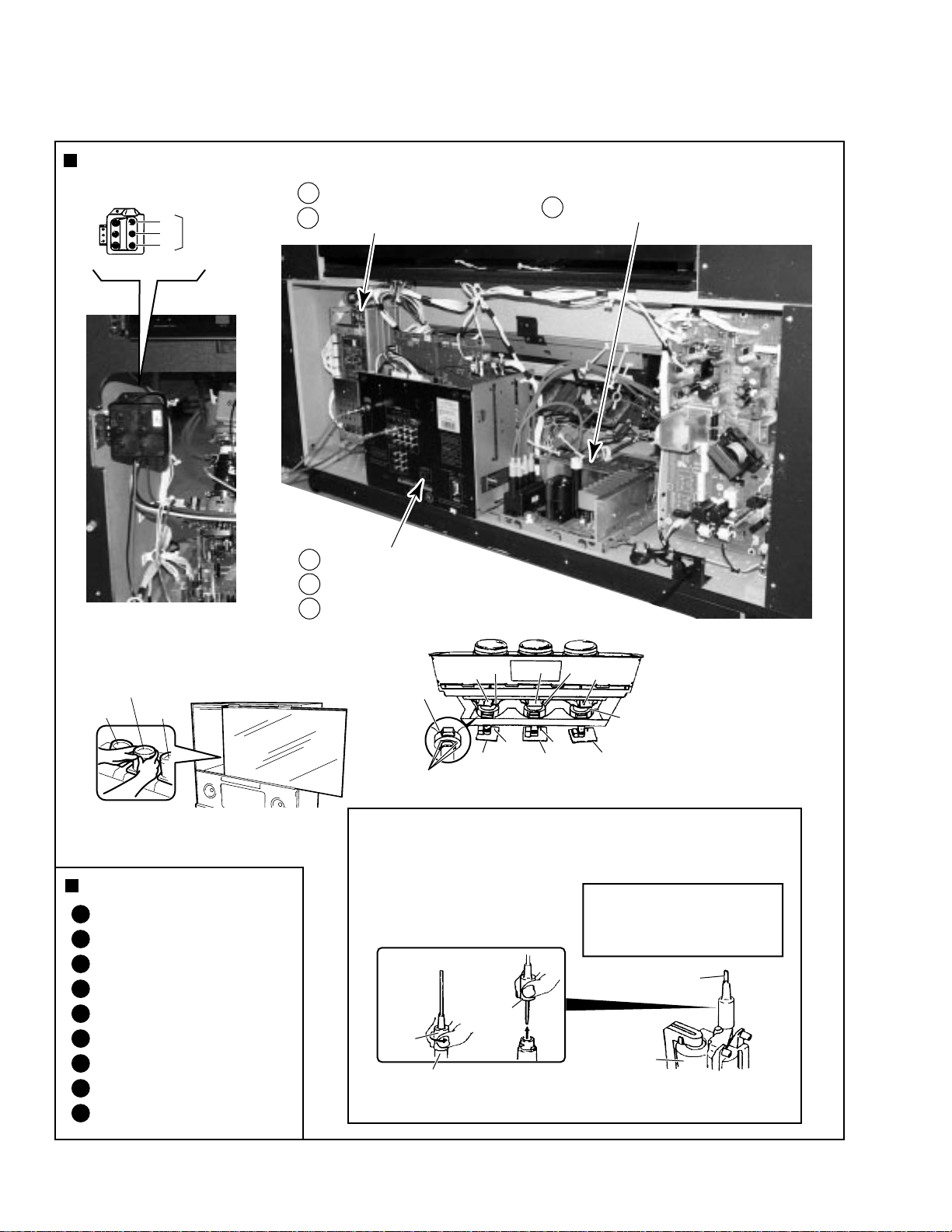
MEASURING METHOD
Disconnect the FBT anode cable as shown below.
Measure at the point where the cable enters the FBT.
Caution : Take extra precaution when
measuring the voltage. High voltage are also
present in surrounding circuit boards. (CRT
assy, POWER SUPPLY assy)
Rubber
Cover
Rear View
Deflection
CRT assy G
Yoke (B)
CRT assy B
Deflection
Yoke
TP-BK TP-GK
B CRT DRIVE
Centering magnet
(Turn in either direction untill cross signal becomes white.)
Holding the rubber cover firmly,
turn counterclockwise and
check that the lock has
been disengaged.
assy
Pull straight up
Deflection
Yoke (G)
G CRT DRIVE
assy
CRT assy R
Deflection
Yoke (R)
R CRT DRIVE
assy
SERVICEMAN WARNING
Before removing the anode cable, turn
off the power, unplug the AC plug and
let the unit discharge for more than 1
minut.
Anode Cable
FBT
Note :
When reconnecting the cable, proceed in the
reverse order. After reconnecting, tug on the
cable to check that it is secure.
196
PRO-610HD, PRO-510HD, SD-582HD5, SD-532HD5
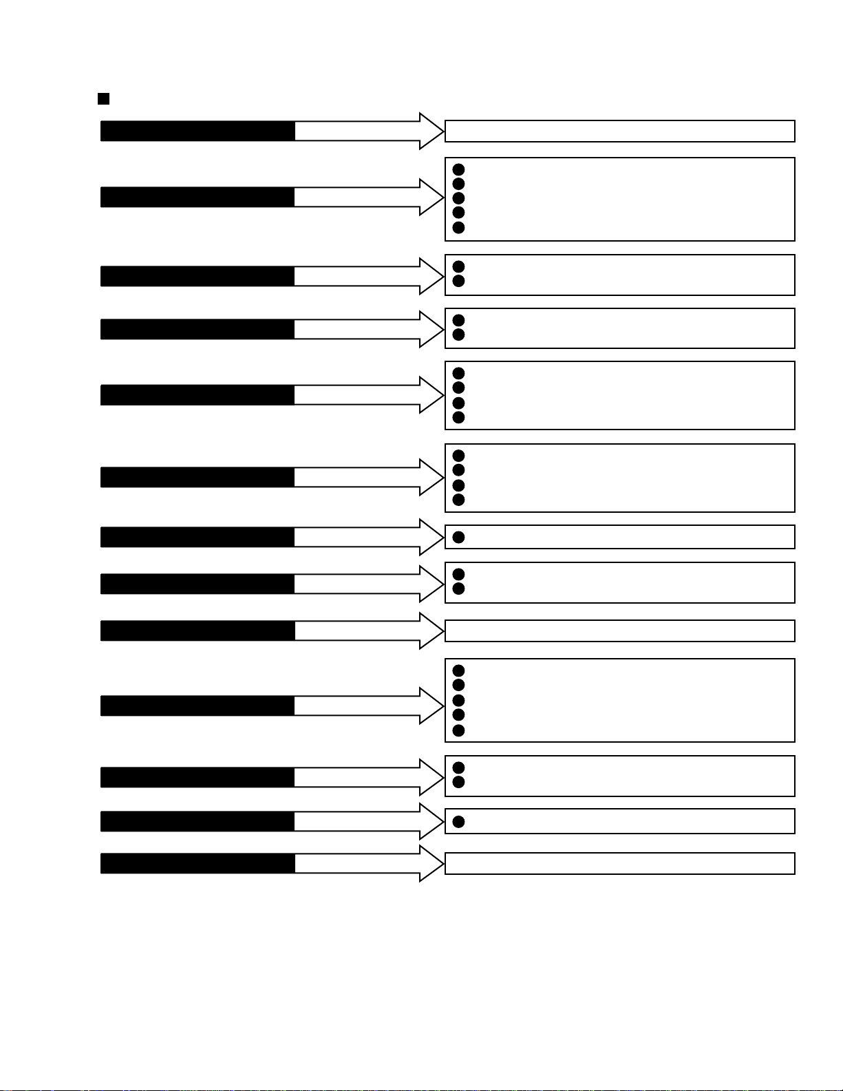
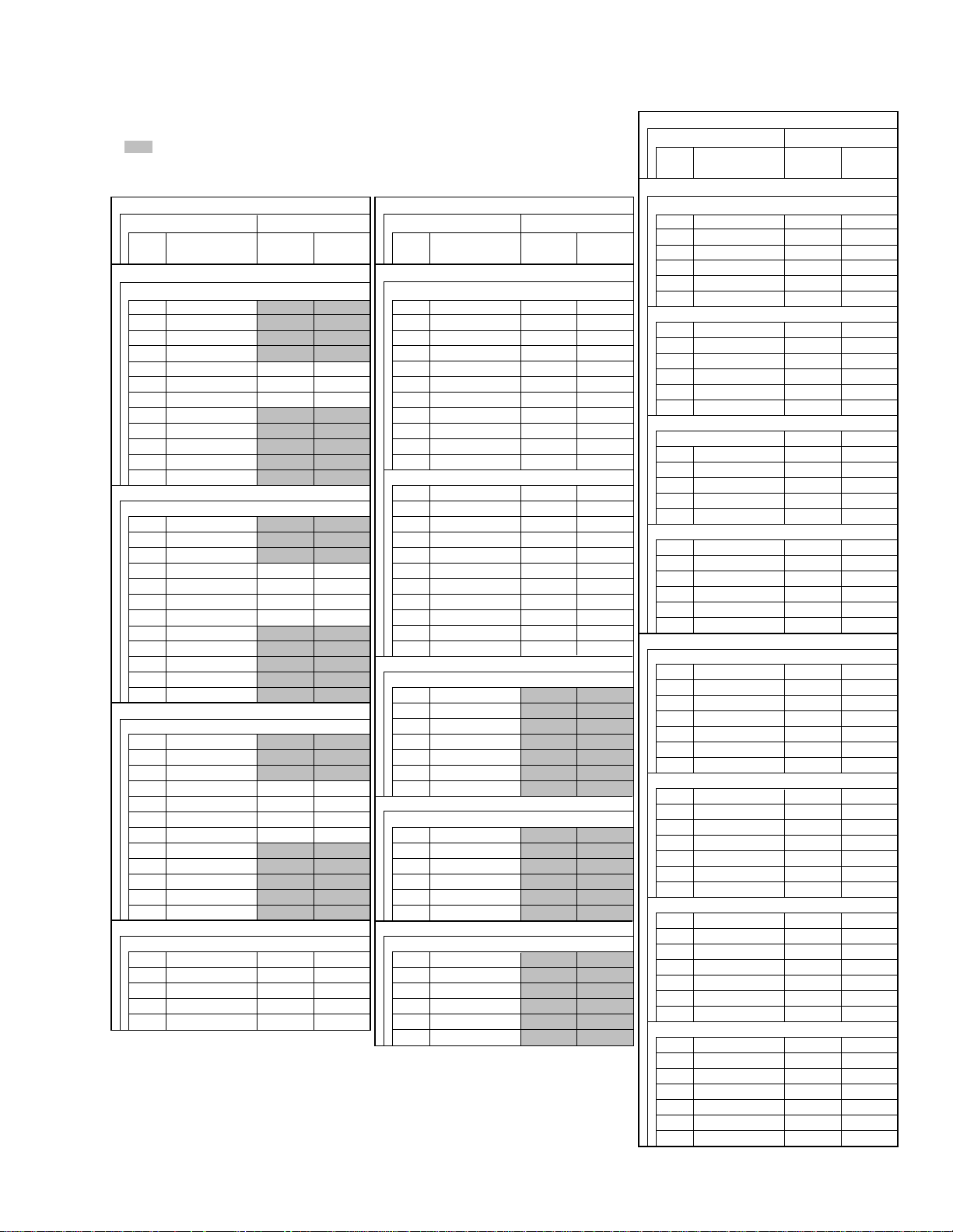
Assembly Adjustment Location Guide
If POWER SUPPLY ASSY
If DEFLECTION SERVICE ASSY
If CONV. AMP ASSY
If R, G or B CRT DRIVE ASSY
If DIGITAL CONV. ASSY
If VIDEO ASSY
is repaired or replaced
is repaired or replaced
is repaired or replaced
is repaired or replaced
is repaired or replaced
is repaired or replaced
No adjustment is required
1
Brightness Adjustment (∗2)
3
Focus Adjustment (VR1: FOCUS VR) (∗2)
5
Screen Size Adjustment (∗2)
6
Convergence Adjustment (∗2)
7
White Balance Adjustment (∗2)
5
Screen Size Adjustment (∗2)
6
Convergence Adjustment (∗2)
1
Brightness Adjustment (∗1)
7
White Balance Adjustment (Composite STD :∗1, Others :∗2)
3
Focus Adjustment (∗2)
4
Test-cross Position Check (∗2)
Screen Size Adjustment (∗2)
5
Convergence Adjustment (∗2)
6
1
Brightness Adjustment (∗2)
7
White Balance Adjustment (Composite STD : ∗1, Others :∗2)
Panel Adjustment (∗1)
8
Panel Adjustment for DTV (∗1)
9
If SIGNAL ASSY
If SUB VIDEO ASSY
If AV I/O ASSY
If CRT ASSY (R, G or B)
If LENS ASSY (R, G or B)
If MIRROR and SCREEN
If OTHER ASSY
Note :
*1: Readjustment necessary
*2: Turn on the power and confirm the screen. When adjustment deviates, it is readjusted if necessory.
is repaired or replaced
is repaired or replaced
is repaired or replaced
is repaired or replaced
is repaired or replaced
is repaired or replaced
is repaired or replaced
White Balance Adjustment (∗2)
7
4
Test-cross Position Check (∗2)
7
White Balance Adjustment (∗2)
No adjustment is required
1
Brightness Adjustment (∗1)
2
Deflection Yoke Adjustment (∗1)
Focus Adjustment (Lens : ∗2, VR1 Focus VR :∗1)
3
Convergence Adjustment (∗2)
6
White Balance Adjustment (Composite STD : ∗1, Others :∗2)
7
3
Focus Adjustment (Lens : ∗1, VR1 Focus VR :∗2)
6
Convergence Adjustment (∗2)
Convergence Adjustment (∗2)
6
No adjustment is required
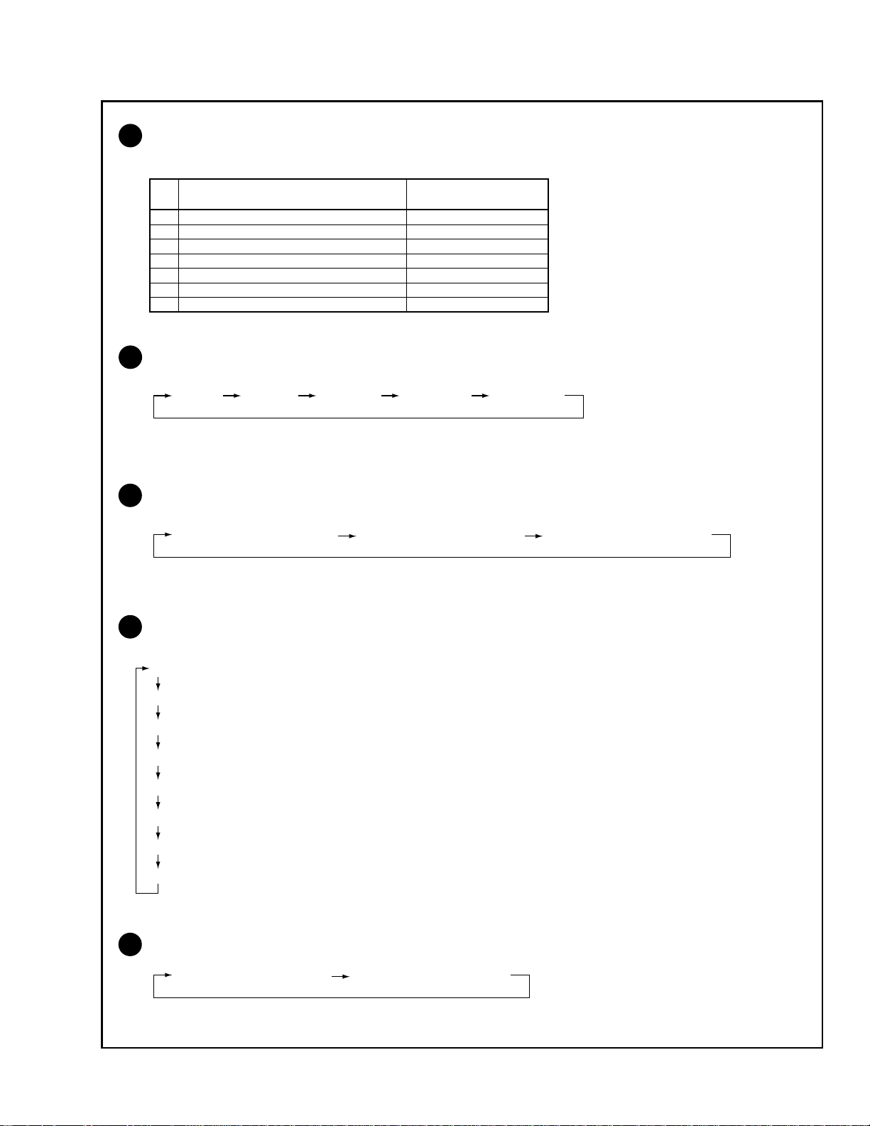
• When the EEPROMs are replaced, check the status of the unit.
• If any IC of the EEPROM is damaged, readjustment of all the items is necessary.
• The necessary adjustment items differ, depending on the assembly or optical part replaced. Check and readjust the adjustment items
corresponding to the replaced assembly or part, following adjustment procedures 1 to 9.
Example: When the DIGITAL CONV. Assy is replaced, perform the following:
3. Focus check/adjustment → 4. Test-cross position check/adjustment → 5. Screen size check/adjustment
→ 6. Convergence check/adjustment
197

PRO-610HD, PRO-510HD, SD-582HD5, SD-532HD5
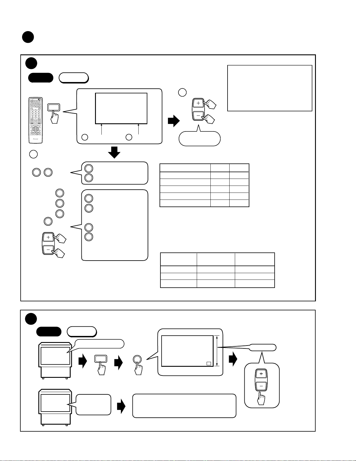
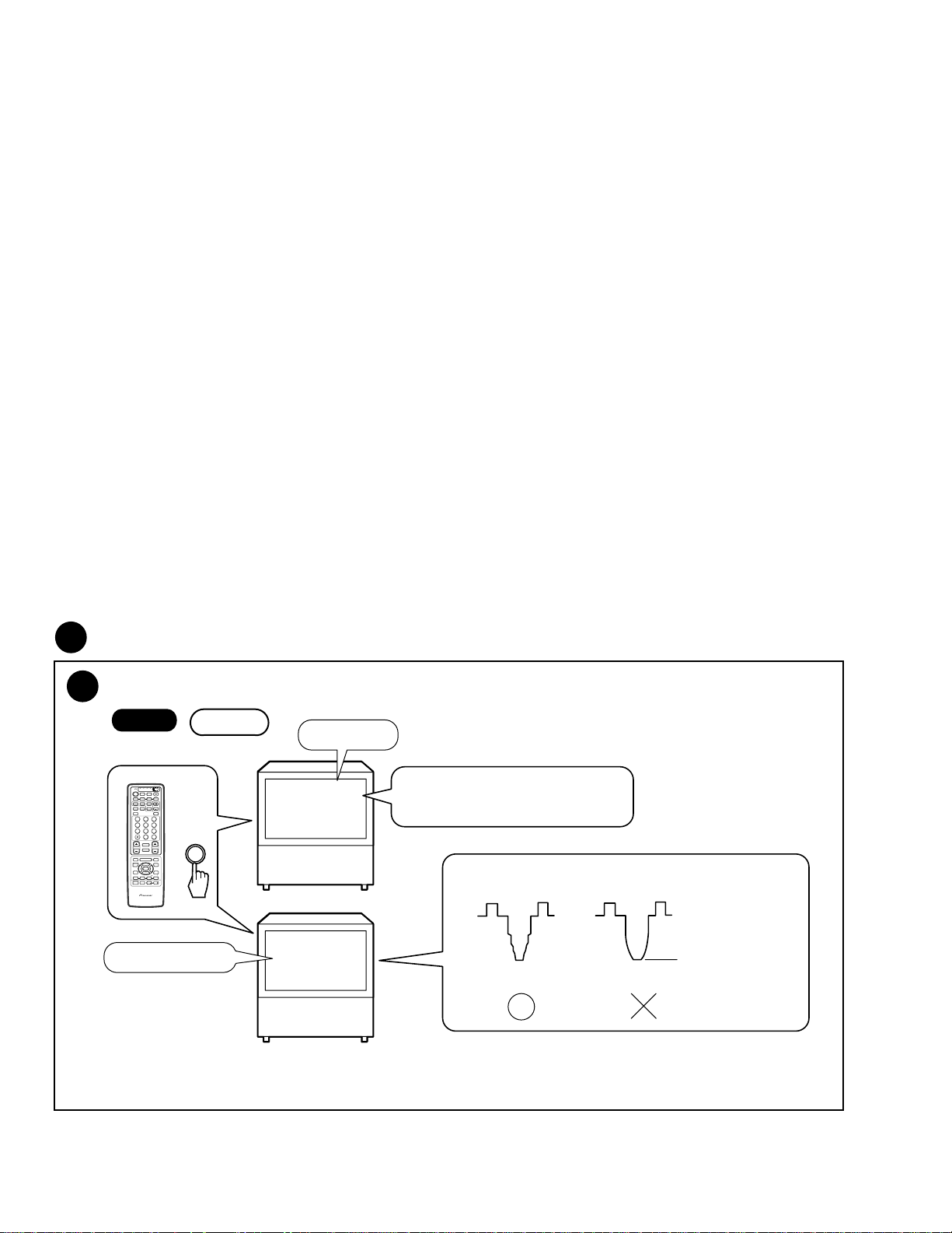
6.4 FACTORY ADJ MODE
Factory Adjustment Mode
Select 1st FACTORY ADJ Mode
Start
TV/
CBL
DVD
VCR
DTV
/SAT
/LD
ON/OFF
POWER
TVTVDTV
INPUT
1 2 3 4
SELECTSEARCH
SPLIT
SCREEN
FREEZE
MODE
ANT
DTV
AUDIO
1
2 3
47586
ENTER
0
¢
CH
RETURN
CH
MUTING
4
EDIT/
DTV/DVD TOP
TV/SAT/DVD
LEARN
MENU
SOURCE
5
POWER
POWER
SET/
2 3
ENTER
8
∞
FAVORITE CH
173¡
RECEIVER
POWER
INPUT
PROJECTION MONITOR RECEIVER
REMOTE CONTROL UNIT
• To enter FACTORY mode, use the
key(s) on the remote control unit or
main unit. To release FACTORY mode,
use the key(s) of the remote control unit
or the main unit, or turn the power off.
If the unit remains in FACTORY mode
without any operation for 8 minutes, it
will be automatically released.
• In FACTORY mode, data for the picture
and audio qualities are standard, and
the FLESH TONE setting is always off.
• When the unit enters FACTORY mode,
settings such as audio muting, MENU,
and SPLIT (two split-screens) are
released.
• The Convergence data which user
adjusted are within the FACTORY
mode. Clear the convergence data by
releasing the FACTORY mode after it is
further within the MANUAL CONVER
mode or OFFSET CONVER mode.
• When the unit exits FACTORY mode,
the TV/CATV mode becomes AIR
(settings of ANT and CH are those last
stored in memory).
• CONVER. OSD (cross hatch) can be
turned on and off cyclically by using the
YELLOW key only during CONVER
mode (MANUAL, AUTO, OFFSET
adjustments).
(Default: The cross hatch is on only in
CONVER. mode.)
TV
SUB CH
POWER
DISPLAY
9
CH
VOL
MENU
DTV/SAT
GUIDE
DTV/(SAT)
INFO
VCR REC
VOLVOL
" ON "
Î
INPUT1
position
Not used in the
adjustment.
Start
1st FAC
Start adjusting
Select 1st FACTORY ADJ mode, then adjust.
Selecting the mode for adjustment operations.
Front panel
2nd FAC-
Press the
switch with
thin rod.
TORY ADJ
mode
picture
RANGE CHECK mode
(MUTING) (MUTING)
(TV/SAT/DVD MENU)
Telop : Red
STD OFFSET mode
( ∞ DOWN)
Telop : Blue
(MUTING)
MANUAL CONVER mode
(SET)
2
Telop : White
(MUTING)
AUTO ADJ mode
2
( 2 LEFT)
Telop : White
(MUTING)
TEST mode
( 3 RIGHT)
Telop : green
Normal
picture
Cyclically
The 2nd FACTORY
ADJ mode is not used
1st FACTORY ADJ
mode
picture
in the adjustment.
PANEL ADJ mode
(CH RETURN)
Telop : White
2
ADJUSTMENT SIZE mode
(ANT)
Telop : Green
ADJUSTMENT MPX mode
(P IN P ON/OFF)(SPLIT)
Telop : Magenta
SIGNAL ADJ mode
( 5 UP)
Telop : White
(MUTING)
(MUTING)
198
DTV PANEL ADJ mode
(DTV)
Telop : Yellow
OTHER OFFSET mode
( )
Telop : Blue
1
COLOR TEMP mode
(Green)
Telop : Blue , Cyclically
4
3
OFFSET CONVER mode
( ÷ DOT)
Telop : White
OTHER OFFSET mode 3
(Blue)
Telop : Blue , Cyclically
5
PRO-610HD, PRO-510HD, SD-582HD5, SD-532HD5
1
OTHER OFFSET mode
To enter the OFFSET mode of each picture quality, use the following keys and codes of the remote control unit:
Key(s) on the Remote
Control Unit
A STD OFFSET MODE DOWN
C COMP (15 kHz) OFFSET MODE P in P CH-, SUB CHD COMP (31 kHz, 33 kHz) OFFSET MODE P in P CH+, SUB CH+
B TV OFFSET MODE RED
V COLOR TEMP B&W for STD DTV MENU
L COLOR TEMP FILM for STD & GAME INFO
T RGB OFFSET MODE CH ENTER
2
The screen size modes change cyclically with each press of the SCREEN key as follows:
1 FULL 2 ZOOM 3 CINEMA 4 NATURAL 5 FULL (HD)
Note :The initial mode is always FULL.
3
The OFFSET CONVER. modes change cyclically with each press of the DOT key as follows:
1 OFFSET CONVER. MODE 1 2 OFFSET CONVER. MODE 2 3 OFFSET CONVER. MODE 3
Note :The initial mode is always OFFSET CONVER. MODE 1.
4
The offset data of the picture quality in COLOR TEMP mode change cyclically with each
press of the GREEN key as follows:
1 J COLOR TEMP NEWS
2 K COLOR TEMP LIVE
3 M COLOR TEMP FILM for MOVIE
4 X COLOR TEMP B&W for MOVIE
5 β COLOR TEMP NEWS for R, G, B
6 γ COLOR TEMP LIVE for R, G, B
7 Y COLOR TEMP FILM for R, G, B
8 Z COLOR TEMP B&W for R, G, B
Note :The initial mode is always COLOR TEMP NEWS when the GREEN key is pressed.
5
The offset data of picture quality change cyclically with each press of the BLUE key as follows:
1 E MOVIE OFFSET MODE 2 F GAME OFFSET MODE
Note :The initial mode is always (1) when the BLUE key is pressed.
199
PRO-610HD, PRO-510HD, SD-582HD5, SD-532HD5
6.5 ADJUSTMENT
1
Brightness Adjustment
TV/
CBL
VCR
DTV
/SAT
POWER
TVTVDTV
INPUT
1 2 3 4
SPLIT
SCREEN
MODE
ANT
DTV
AUDIO
1
2 3
47586
0
¢
CH
RETURN
CH
MUTING
4
EDIT/
TV/SAT/DVD
LEARN
MENU
SOURCE
5
POWER
POWER
SET/
2 3
ENTER
8
∞
FAVORITE CH
173¡
RECEIVER
POWER
INPUT
PROJECTION MONITOR RECEIVER
REMOTE CONTROL UNIT
Start
1st FAC
Input signal : Black Burst (INPUT 1)
Black burst
0
0
CH
: CUT-R
VOL
b
0
4
ADJUTMENT OFFSET
BRIGHT
DVD
/LD
ON/OFF
SELECTSEARCH
SUB CH
FREEZE
(DOWN)
DISPLAY
9
∞
CH
ENTER
VOL
DTV/DVD TOP
MENU
DTV/SAT
GUIDE
DTV/(SAT)
INFO
VCR REC
VOLVOL
Î
ADJUTMENT OFFSET
CUTR
Telop: Blue
Data value
b
: CUT-G
CH
: CUT-B
Cut off level
(180V DC)
GND
VOL
or
Cut off level
(180V DC)
GND
B CRT
DRIVE
ASSY
VR5201
CH1 CH2
(X) (Y)
CH1 CH2
(X) (Y)
G CRT
DRIVE
ASSY
R CRT
DRIVE
ASSY
TP-GK
Cut off level
(180V DC)
GND
TP-RK
Oscilloscope
CH1 CH2
(X) (Y)
Oscilloscope
R CRT
DRIVE
ASSY
VR5101
B CRT
DRIVE
ASSY
TP-BK
Oscilloscope
When the DEFLECTION SERVICE Assy or VIDEO Assy is
replaced, check the following to confirm if the above
adjustment is necessary:
(1) Make a note of the data of CUT R, CUT G, CUT B, and
BRIGHT. (1st FAC) ( ∞ DOWN)
(2) Input "0" as parameters for (1) and check TP-RK, TP-GK
and TP-BK of the CRT DRIVE assembly. If the levels are
within 180 V ±5 V, the adjustment is not necessary.
Input the noted data.
If the levels are not within the above level, proceed with
the above adjustment.
200
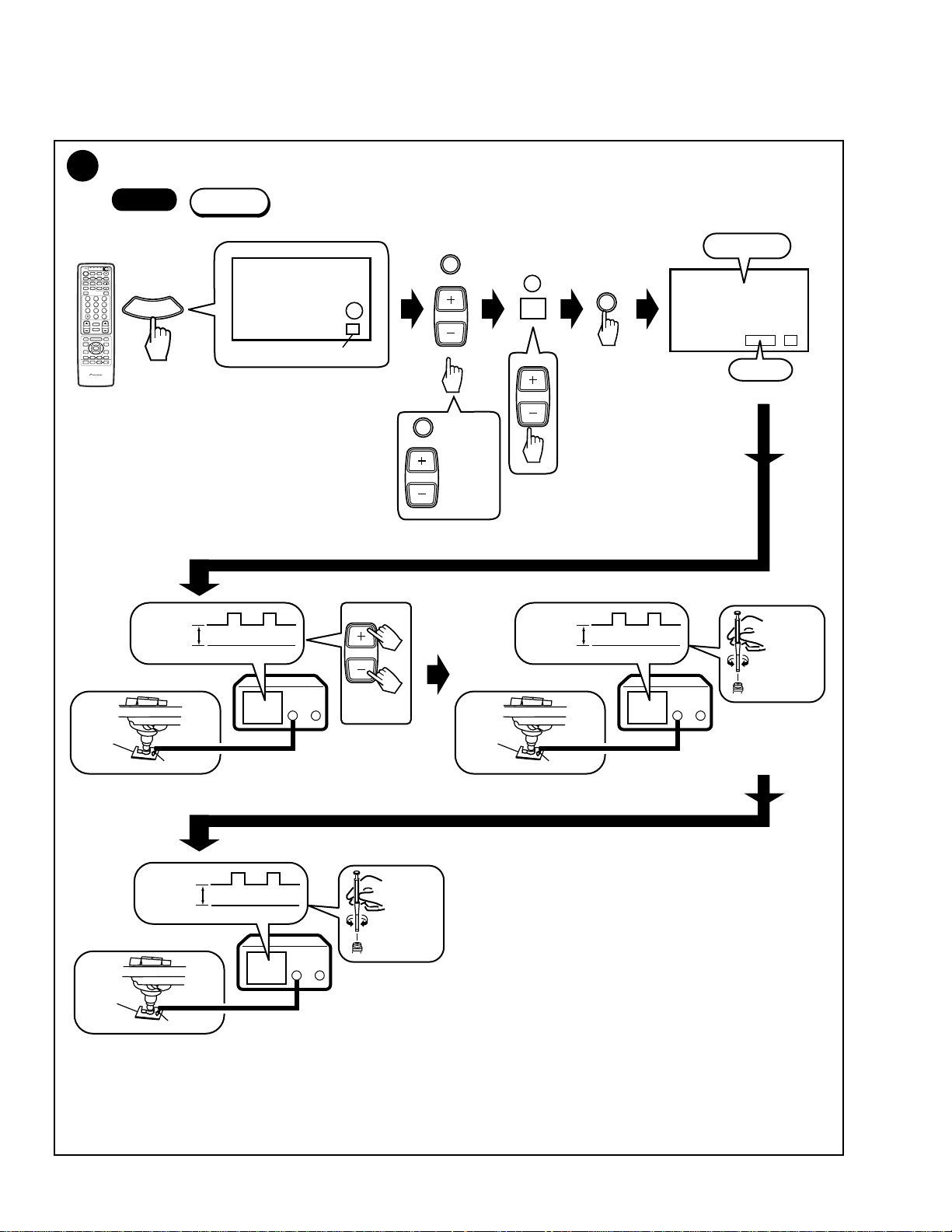
2
Deflection Yoke Adjustment
PRO-610HD, PRO-510HD, SD-582HD5, SD-532HD5
2
• Turn the deflection yoke of the replaced CRT so that the cross
hatch of the color corresponding to the replaced CRT converges
with that of the CRTs not replaced.
• When a CRT is replaced, check the position of the VM (Velocity
Modulation) yoke.
Deflection Yoke Lean Adjustment
-1
Start
• Input a stable signal (e.g. from an LD player or SG) to
the INPUT 1 connector.
• MENU → SETUP → Enter the MULTI-POINT (FULL) in
the CONVERGENCE.
• The cross hatch disappears if there is no operation with
the remote control unit for about 8 minutes. If the cross
hatch disappears, repeat the above operation with the
remote control unit.
Cross hatch
Turn to adjust.
Deflection
yoke
Deflection
Yoke (L3)
Deflection
Yoke (L2)
CRT ASSY B
B.CRT DRIVE
Assy
Centering magnet
(Turn in either direction until cross signal
becomes white.)
CRT ASSY G
G.CRT DRIVE
Assy
Approx. 1cm
Deflection
Yoke (L1)
CRT ASSY R
R.CRT DRIVE
Assy
2
Screen Center Adjustment
-2
Start
• Move the centering magnet of the deflection yoke for the
replaced color so that the horizontal and vertical lines at the
center of the screen align with the lines for a color not replaced.
Cross hatch
• Secure the centering magnet from moving after adjustment is
finished.
Deflection
yoke
Centering magnet
(Turn in either direction until cross signal becomes white.)
201
PRO-610HD, PRO-510HD, SD-582HD5, SD-532HD5
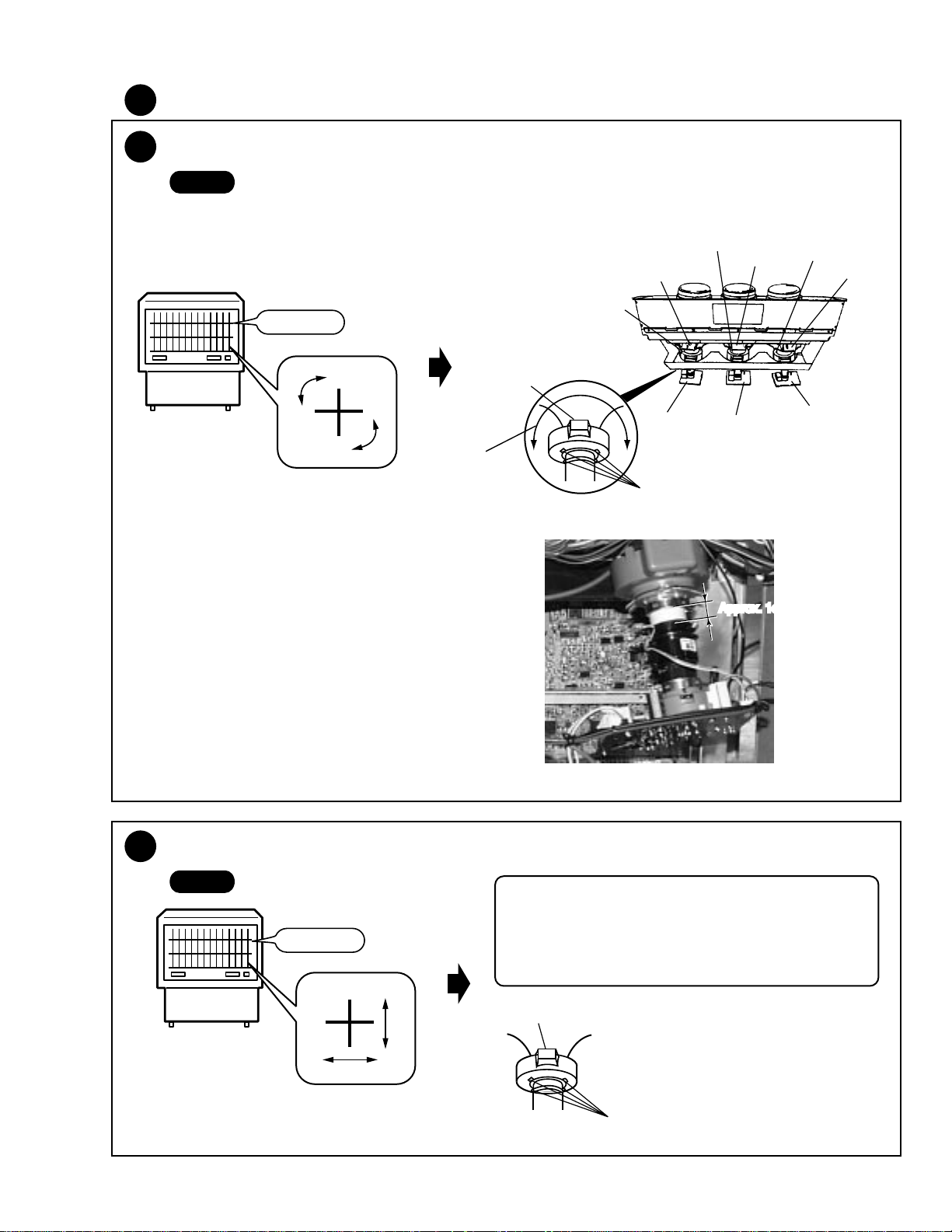
3
Focus Adjustment
3
-1
Focus Adjustment of Lens Assy
Start
Cross hatch
3
Focus VR Adjustment
-2
Cross hatch
Lens assy
(For Red)
Lens assy
(For Green)
Lens assy
(For Blue)
"Best focusing"
Focus VR (VR1)
B
G
FOCUS VR
R
Turn the Focus VR for best focusing.
202
PRO-610HD, PRO-510HD, SD-582HD5, SD-532HD5
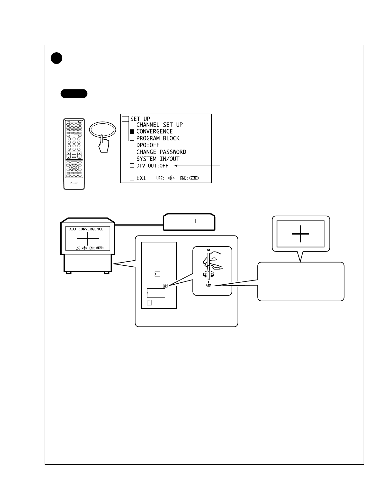
Test-cross Position Check
4
• Check the test-cross position. If it is located within ± 20 mm from the center of the screen, no adjustment is required.
If it is not, adjust the position as follows:
• Input a stable NTSC (480i) signal (e.g. from an LD player) and adjust the position.
Start
MENU → SETUP → CONVERGENCE → FULL
TV/
CBL
DVD
VCR
DTV
/SAT
/LD
ON/OFF
POWER
TVTVDTV
INPUT
1 2 3 4
SELECTSEARCH
SPLIT
SCREEN
FREEZE
MODE
ANT
DTV
AUDIO
1
2 3
47586
0
¢
CH
RETURN
CH
MUTING
4
EDIT/
TV/SAT/DVD
LEARN
MENU
SOURCE
5
POWER
POWER
SET/
2 3
ENTER
8
∞
FAVORITE CH
173¡
RECEIVER
POWER
INPUT
PROJECTION MONITOR RECEIVER
REMOTE CONTROL UNIT
SUB CH
9
CH
ENTER
VOL
DTV/DVD TOP
DTV/SAT
VCR REC
SET/
ENTER
DISPLAY
MENU
GUIDE
DTV/(SAT)
INFO
VOLVOL
Î
Notes:
• The item of DTV OUT might not be displayed when
the DTV BIB (built-in DTV tuner) is not connected.
DIGITAL
CONV.
ASSY
IC1410
L1651
IC1656
(LD player)
L1651
Adjust the position so that the
test cross is placed at the center
of the screen.
203
PRO-610HD, PRO-510HD, SD-582HD5, SD-532HD5
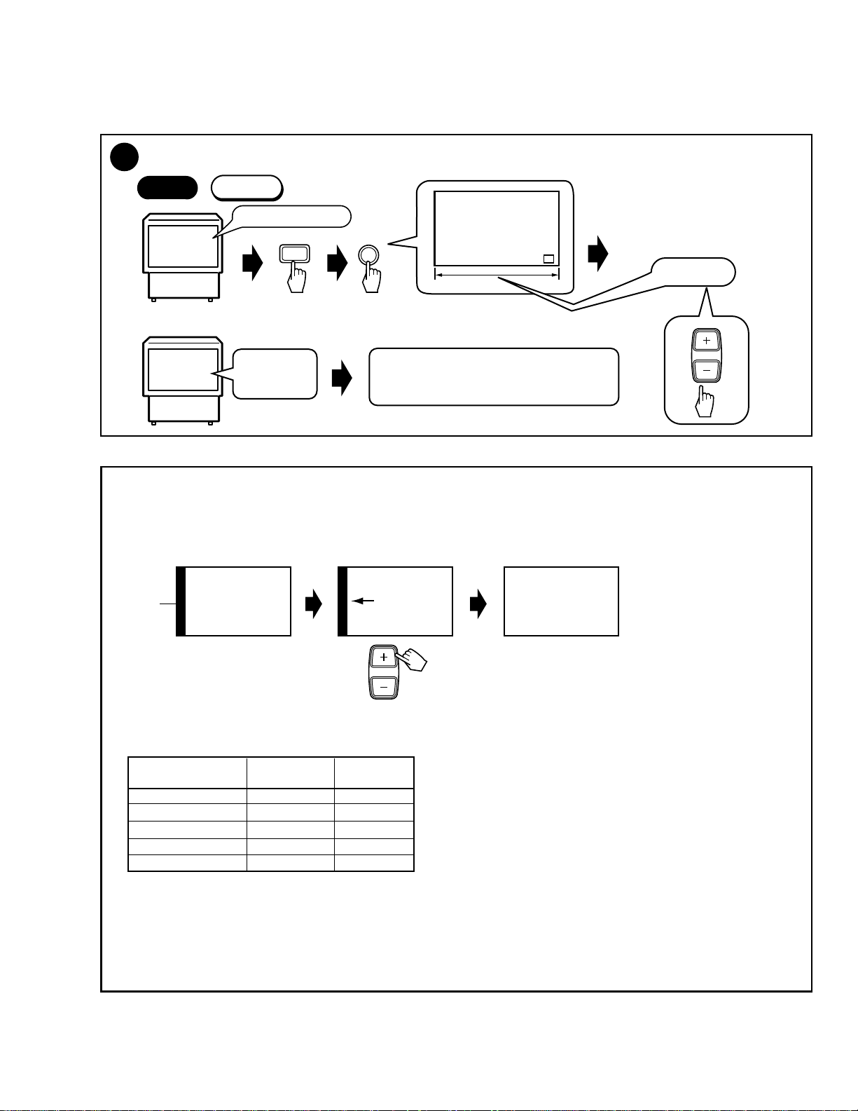
5
Screen Size Adjustment
Check if both vertical and horizontal sizes are within 91% ±2%. If they are not, perform the size adjustment as follows:
-1
Start
TV/
CBL
DVD
VCR
DTV
/SAT
/LD
ON/OFF
POWER
TVTVDTV
INPUT
1 2 3 4
SELECTSEARCH
SPLIT
SUB CH
SCREEN
FREEZE
MODE
ANT
DTV
DISPLAY
AUDIO
1
2 3
47586
9
CH
ENTER
0
¢
CH
RETURN
VOL
CH
MUTING
4
EDIT/
DTV/DVD TOP
TV/SAT/DVD
LEARN
MENU
MENU
SOURCE
DTV/SAT
5
POWER
POWER
GUIDE
SET/
2 3
ENTER
DTV/(SAT)
INFO
8
∞
VCR REC
FAVORITE CH
173¡
RECEIVER
POWER
INPUT
VOLVOL
PROJECTION MONITOR RECEIVER
Î
REMOTE CONTROL UNIT
b
Size mode
1
Size Mode
1st FAC
ANT
2
ADJUTMENT FULL SIZE
H SIZE -24
Telop: Green
b
Size mode
: H Size (15 kHz)
1
: V Size
2
a
Data value
5
3
3
: H PHA (15K)
6
6
9
0
CH
or
: H SIZE (33K)
(fixed value D can be
varied)
9
: H PHA (31K RGB)
0
: H PHA (33K RGB)
CH +
: H PHA (31kHz)
: H PHA (33kHz)
CH –
Note :
• The adjustment is unnecessory for D so that is set in
factory shipment by the most suitable value.
However, please adjust it when a screen is missed when
displayed the HD source on the screen.
• For H PHA, refer to the section "• Reference."
• Mode for roughly adjusting the
Note :
Screen mode : FULL
a
Data value
horizontal and vertical sizes of the
main deflection.
• In this mode, the color is green only,
screen size is FULL and the contrast
is +10.
• The above settings are cleared when
VOL
or
this mode is exited.
-128 to 126
(even data only)
Table on H SIZE and V SIZE data
Picture Quality Mode H SIZE V SIZE
NATURAL WIDE A B
CINEMA WIDE A B
ZOOM A B
FULL A B
FULL for HD A+D B
• Perform the H SIZE and V SIZE adjustments only in FULL
mode (NTSC MONOSCOPE signal input).
• Release the FACTORY mode, then change the screen mode
and confirm that the picture is not missing.
A, B : Adjustment values
D : Fixed values
A+D : Addition of A and D
The factory-preset values are as follows:
Key No.
1 : H SIZE (15K) Approx. 16 ± 30 Approx. 16 ± 30
2 : V SIZE Approx. -50 ± 30 Approx. -50 ± 30
6 : H SIZE (33K) Approx. 70 ± 30 Approx. 70 ± 30
Note: Varies depending on the factory-preset value.
PRO-610HD SD-582HD5
PRO-510HD SD-532HD5
204
5
Vertical Size Adjustment
-2
Start
1st FAC
INPUT 1:Monoscope
or
INPUT TV
General
broadcasting
ANT
Green screen
2
V.SIZE
Adjust the size so that the picture is completely
displayed on the screen.
Note :
Screen mode : FULL
91% ± 2%
VOL
PRO-610HD, PRO-510HD, SD-582HD5, SD-532HD5
5
-3
Horizontal Size Adjustment
Start
1st FAC
INPUT 1:Monoscope
ANT
1
Note :
Screen mode : FULL
Green screen
H.SIZE
Note :
• After the V. SIZE adjustment,
enter the H. SIZE adjustment
by pressing "1" key.
• After the H. SIZE adjustment,
check that V. SIZE is 91± 2%.
If not, readjust the V. SIZE.
91% ± 2%
or
INPUT TV
General
broadcasting
Adjust the size so that the picture is completely
displayed on the screen.
VOL
• Reference
The H PHASE adjustment is required if the left or right part of the screen becomes black, as illustrated below, depending on the format
of the input signal (Ex. component 31.5 kHz, RGB 33K etc.).
Ex. Component 31K
Black
Animation Animation
screen
CH
Move the part of animation leftward with CH+.
Animation
• About H. PHASE
In principle, adjustment of the data for the H. PHASE is not required.
Check whether the H. PHASE data are the factory-preset values, as indicated below:
PRO-610HD SD-582HD5
Key No.
3 : H PHA (15K) 80 80
CH+ : H PHA (31K) 36 40
CH- : H PHA (33K) -14 -8
9 : H PHA (31K RGB) 26 30
0 : H PHA (33K RGB) -26 -20
The screen moves to the right or the left if the above data are in variance. (See the above figures.)
Note :
H PHASE is set in factory shipment by the most suitable value. But, there is the case that screen is missed as an upper figure occurs
by the signal format of other apparatus to be connected to.
A screen can be improved as the following by the readjustment. However, attention is necessory because in convenience may occur
when connected to another apparatus.
PRO-510HD SD-532HD5
15K : CONPOSITE, S COMPONENT (480i)
31K : COMPONENT (480P)
33K : COMPONENT (1080i)
205
PRO-610HD, PRO-510HD, SD-582HD5, SD-532HD5
6
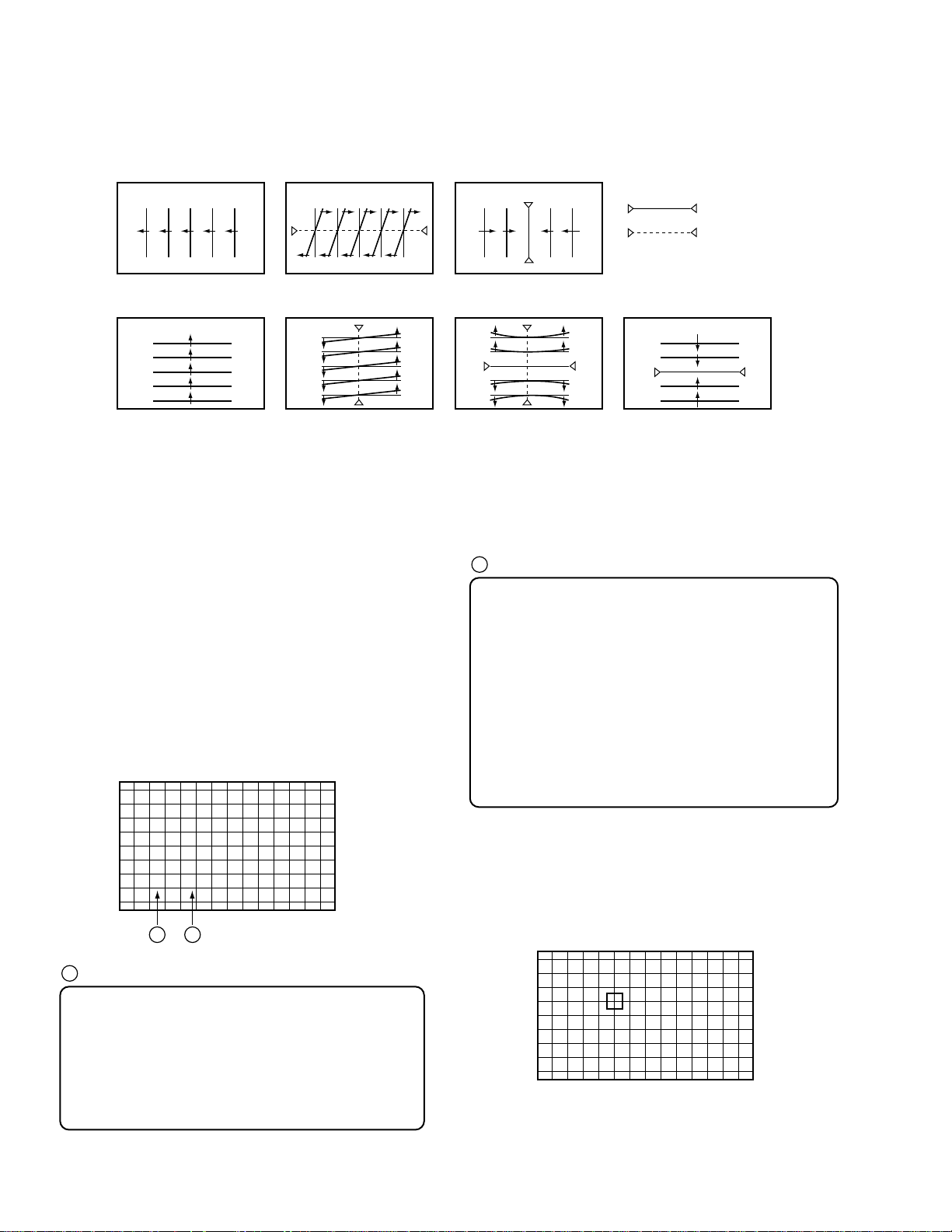
CONVERGENCE ADJUSTMENT
1. Procedures
1. When replacinf the DIGITAL CONV. Assy, replace the EEPROM
of new DIGITAL CONV. Assy with the EEPROM of old
DIGITAL CONV. Assy.
2. Check the initial data for the convergence adjustment.
3.Perform the coarse adjustment for the green to roughly correct
distortion of the green.
4.Fine-adjust the green to eliminate any distortion. The green
becomes the standard for the red and the blue.
If necessary, repeat steps 3 and 4. Green adjustment is completed.
5. Perform the coarse adjustment for the red by roughly converging
the red with the green.
6.Fine-adjust the red until the red is completely converging with
the green.
If necessary, repeat steps 5 and 6. Red adjustment is completed.
7. Perform the coarse adjustment for the blue by roughly converging
the blue with the green.
8. Fine-adjust the blue until the blue is completely converging with
the green.
If necessary, repeat steps 7 and 8. Blue adjustment is completed.
9. Display the green, red, and blue colors at the same time to check
the convergence. Readjust the convergence if necessary.
The data stored in the EEPROMs are as follows:
IC1410
OFFSET CONVER. MODE 1 (DFH, DFV)
OFFSET CONVER. MODE 3
Factory-preset values for convergence
User-adjusted values for convergence (CENTER, MULTI-POINT)
IC1656
OFFSET CONVER. MODE 1 (HDP)
OFFSET CONVER. MODE 2
3.2 Confirmation of convergence data
The convergence coarse adjustment modes change cyclically, as
shown below, with each press of the DOT key in FACTORY mode:
Convergence coarse adjustment
DOT key (pressed once) : OFFSET CONVER. MODE 1
DOT key (pressed twice) : OFFSET CONVER. MODE 2
DOT key (pressed three times) : OFFSET CONVER. MODE 3
Cyclical change
2. Prior to Adjustment
There are five screen modes, and convergence adjustment is required
for each mode. For adjustment, input the following video signal:
Table 1 Input signal
Screen mode Input signal
1. FULL (FULL, 4:3 NORMAL)
2. ZOOM (ZOOM) NTSC (480i) signal
3 CINEMA (CINEMA WIDE)
4. NATURAL (NATURAL WIDE)
5. FULL for HD (HD/DTV) HD/DTV (1080i) signal
NTSC : Stable signal source, such as an SG or an LD/DVD player
HD : Stable signal source, such as an HD SG or a DTV tuner (SH-
D09, etc.) Only PRO-610HD5/510HD5 can use the SH-D09.
When CRTs are replaced or when the deflection yoke is moved,
perform the deflection yoke adjustment, horizontal and vertical size
adjustments, and centering magnet adjustments before the
convergence adjustment. (See Pages 201, 204 and 205)
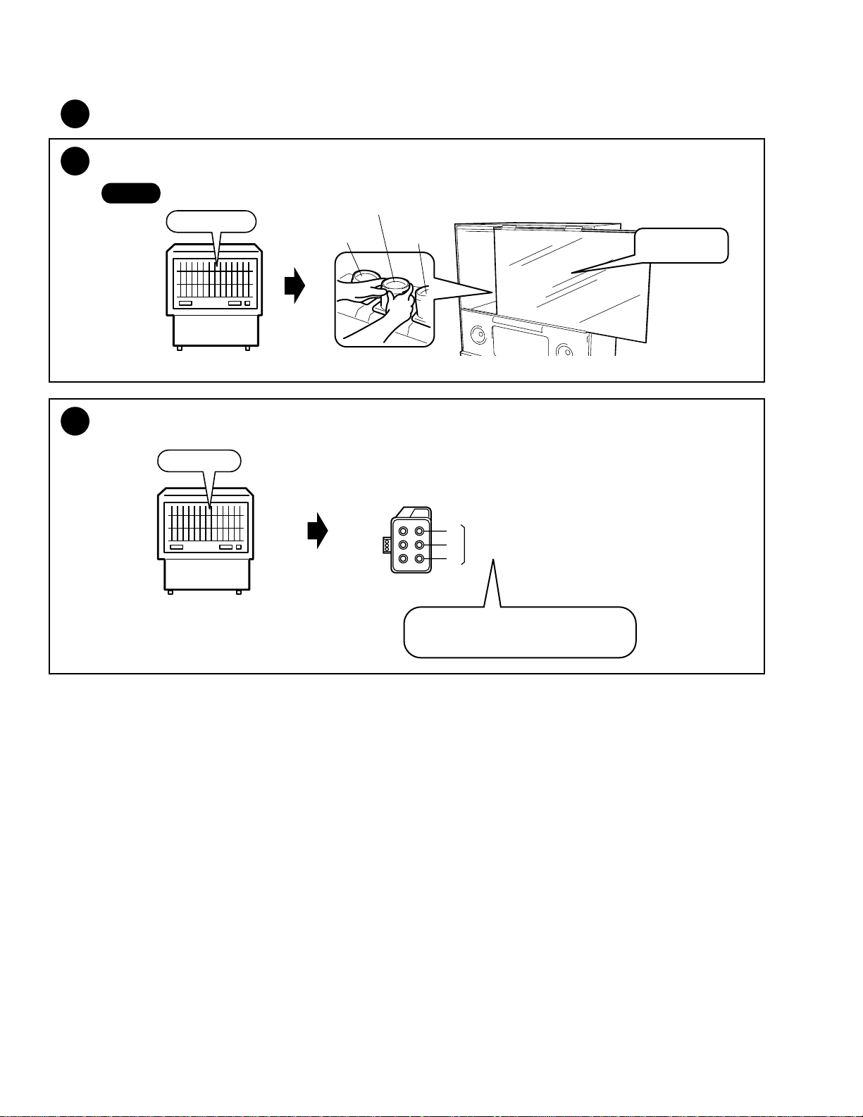
3. Convergence Adjustment
3.1 Replacement of the EEPROMs inside
the DIGITAL CONV. Assy
IC1410 24LC128P
IC1656 24LC08B (I) P
DIGITAL CONV. ASSY
Shield Case
IC1410
IC1656
Check whether the data of MODE 1 and MODE 2 are as shown in
Table 2.
The cross-hatch signal is generated inside the unit, and is automatically displayed in OFFSET CONVER. mode and MANUAL
CONVERGENCE mode. You can turn on and off the cross-hatch
signal with the YELLOW key.
Screen indication
F
A
Screen mode:
F : FULL Z : ZOOM C : CINEMA
N : NATURAL H : FULL for HD
The Screen modes change cyclically with each press of the
SCREEN mode key.
A
DFH
B
0F0
C
B
Adjustment items can be selected with the numeric keys.
See Table 2.
C
Adjustment data:
MAX 1FF
CNT 000
MIN 200
Data can be adjusted with the VOL+ and VOL- keys.
100
001
3FF
2FF
206
PRO-610HD, PRO-510HD, SD-582HD5, SD-532HD5
Table 2 OFFSET CONVER DATA
OFFSET CONVER MODE 1
Numeric
OFFSET CONVER MODE 2
Numeric
The above offset convergence values are common to the PRO-610
HD/510HD and SD-582HD5/532HD5.
Adjustment
Key
1 DFH 0F0 0D0 0D0 0D0 100
2 DFV 070 070 070 070 070
3 HDP 010 010 010 010 010
Key
1 HFP 0CC 0CC 0CC 0CC 0D0
2 HCP 00F 00F 00F 00F 015
3 HTP 047 047 047 047 044
4 HHD 0EE 0EE 0EE 0EE 0E9
5 HPW 00C 00C 00C 00C 00F
6 V1C 01F 029 025 022 01D
7 V1S 000 000 000 000 000
8 VFP 01D 02D 013 033 065
Item
Adjustment
Item
F
FULLZZOOMCCINEMANNATURALHHD FULL
F
FULLZZOOMCCINEMANNATURALHHD FULL
Screen Mode
Screen Mode
If the offset convergence values are as indicated in Table 2,
proceed to 3.3. If the values are not the same, adjust the values
with the numeric keys and VOL +/– keys.
Example:
To check HDP in ZOOM mode of OFFSET CONVER. MODE 1
1 Enter the FACTORY mode.
2 Enter the OFFSET CONVER. MODE 1 by pressing the DOT
key once.
3 Enter the ZOOM screen mode by pressing the SCREEN mode
key once. (When the unit enters FACTORY mode, the screen
mode automatically becomes FULL.)
4 Check the indication on the screen by pressing the numeric
key 3.
Indication at the bottom of the screen : Z HDP 010
If the adjustment value is 010, adjustment is not required.
If the adjustment value is other than 010, adjust with the VOL
+ or VOL- key so that the value becomes 010.
The cross-hatch signal is generated inside the unit, and is automatically displayed in OFFSET CONVER. mode and MANUAL
CONVERGENCE mode. You can turn on and off the cross-hatch
signal with the YELLOW key.
Screen indication
RH
STATIC
001
F
A B C D
A
Screen mode:
F : FULL
Z : ZOOM
C : CINEMA
N : NATURAL
H : FULL for HD
The Screen modes change cyclically with each press of the
SCREEN mode key.
B
Cyclically changes with the CH+ or CH- key as follows:
RH RV BH
GV GH BV
C
Adjustment items can be selected with the numeric keys.
See Table below.
• Waveforms adjustable in the coarse adjustment
of the green
Numeric Key GH GV
0 STATIC STATIC
1 SKEW SKEW
6 PIN
8 SIZE SIZE
3.3 Coarse Adjustment of the Green
(Proceed with 3.3 and afterwards when the DIGITAL CONV.
Assy is not replaced.)
Select adjustment items (STATIC and SIZE of vertical and
horizontal lines, etc.) for each GH and GV, and adjust to roughly
eliminate distortion. (For GV, peripheral pin distortion adjustment is necessary.)
Press the DOT key three times to enter OFFSET CONVER.
MODE 3.
Press the SCREEN mode key and proceed with the adjustment for
each screen mode.
D
Adjustment data:
MAX 1FF
100
001
CNT 000
3FF
2FF
MIN 200
Data can be adjusted with the VOL+ and VOL- keys.
207
PRO-610HD, PRO-510HD, SD-582HD5, SD-532HD5
• Pattern for each adjustment item
Key No.
GH
Key No.
STATIC
STATIC
`
`
Key No.
SKEW
Key No.
SKEW
1
1
Key No.
SIZE
Key No.
PIN
8
6
Key No.
SIZE
= Fixed position
8
GV
Note 1: When the green CRT is replaced, or when the deflection yoke for the green is replaced, prior to the convergence adjustment,
Note 2: When the CONVER. AMP Assy or DIGITAL CONV. Assy is replaced, make coarse adjustment as shown in 3.3 above.
3.4 Fine-adjustment of the Green
Enter MANUAL CONVERGENCE mode by pressing the
SET/ENTER key, and make adjustments. Repeatedly make the
coarse adjustment as shown in 3.3 if necessary. Proceed with the
adjustment for each screen mode. Adjusted values for the green
become the standard for the red and the blue.
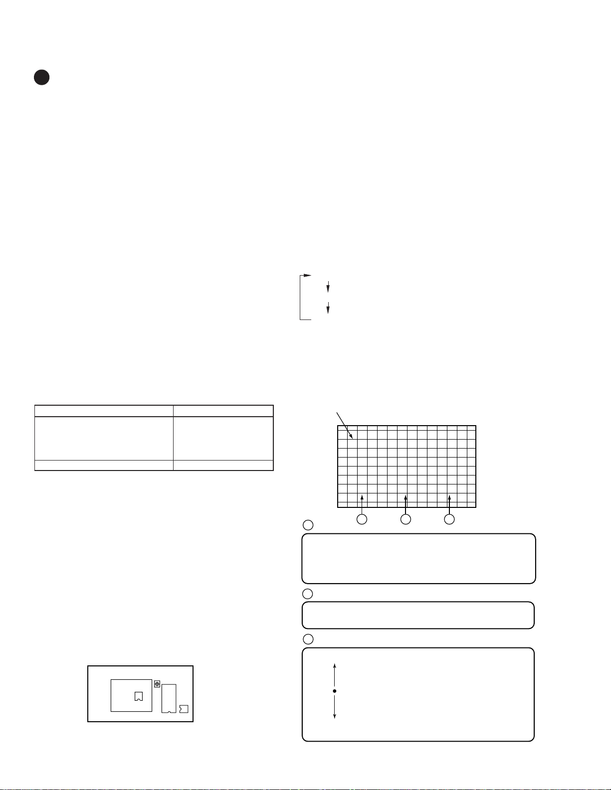
3.4.1
In MANUAL CONVERGENCE mode entered by pressing the
SET/ENTER key, the display becomes as shown below:
tune the center of the image to the center of the screen by turning the centering magnet.
B
Coordinates where the cursor (adjustment point) is located
There are 72 adjustment points (8,9) on the coordinates for
FULL, ZOOM, CINEMA, NATURAL and FULL for HD modes,
but the coordinates actually used for adjustment are as follows
(the coordinates outside the ranges indicated below are outside
the screen, and adjustment will not have any effect on the
screen):
FULL : (0, 1) to (7, 9)
ZOOM : (0, 1) to (7, 7)
CINEMA : (0, 1) to (7, 8)
NATURAL : (0, 1) to (7, 8)
HD for FULL : (0, 1) to (7, 9)
Screen indication
(X, Y): X=abscissa, Y=ordinate
Some coordinates may be outside the screen and invisible.
The point at coordinates (0, 0) is at the upper left of the screen.
F
(0 , 0)
A B
A
Screen mode:
F : FULL
Z : ZOOM
C : CINEMA
N : NATURAL
H : FULL for HD
The Screen modes change cyclically with each press of the
SCREEN mode key.
208
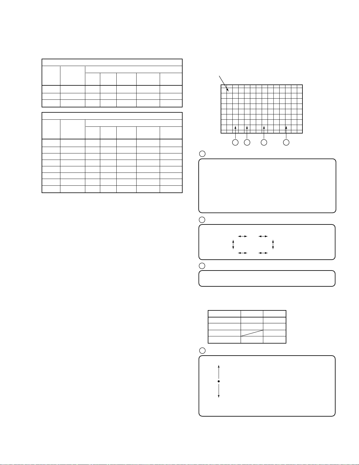
3.4.2
Move the cursor to a point to be adjusted with the cursor move
keys.
Screen indication
F
(4 , 4)
Note: The actual shape of the cursor is " [ ] ".
The position of the cursor in this figure is different from the actual
position on the screen.
PRO-610HD, PRO-510HD, SD-582HD5, SD-532HD5
3.4.3
Press the SET/ENTER key when the point to be adjusted is
determined.
Screen indication
FG
A B
Screen mode Coordinates where the adjustment
A
Color to be adjusted:
G: GREEN, R: RED, B: BLUE
To change colors, use the CH+ or CH- key.
The colors change cyclically as follows:
With CH+ : R → B → G → R
With CH- : R → G → B → R
B
H:000 V:000(4 , 4)
point is located
3.4.4
When adjustment of the selected point is finished, press the
SET/ENTER key, then adjust the other adjustment points by
repeating 3.4.1 to 3.4.4.
3.4.5
Make the adjustment for the green in each screen mode, and use
the green as the standard screen for the red and the blue. To
change screen modes, use the SCREEN mode key.
Note: Some coordinates for adjustment points are located outside
the screen. Be sure not to make adjustments on those
points, because adjustment of those coordinates will have
little effect on the screen.
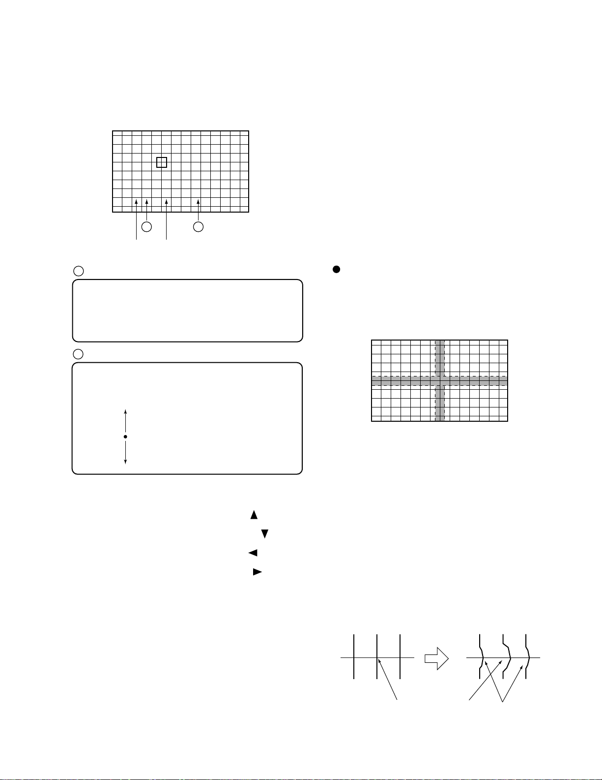
Adjustment Technique
1st step
Adjust so that the vertical and horizontal lines forming a cross at
the center of the screen become straight. Check also the screen
size and the linearity of the horizontal and vertical lines.
H: ∗∗∗ Adjustment data in the horizontal direction
V: ∗∗∗ Adjustment data in the vertical direction
( ∗∗∗= hexadecimal number)
Data MAX 1FF
100
001
CNT 000
3FF
2FF
MIN 200
For adjustment, move the Line to the desired direction with the
cursor keys.
To move the Horizontal Line upward, press the " " key.
(The value decreases.)
To move the Horizontal Line downward, press the " " key.
(The value increases.)
To move the Vertical Line to the left, press the " " key.
(The value decreases.)
To move the Vertical Line to the right, press the " " key.
(The value increases.)
• To select one color, use the SEARCH key for the red, SELECT
key for the green, FREEZE key for the blue. Pressing this key
toggles color muting on or off.
• To mute all the colors, press the DISPLAY key. To release
muting, press the SEARCH, SELECT, or FREEZE key.
• To erase the cross hatch, press the YELLOW key.
Pressing this key toggles between display of the cross hatch
screen and the input screen.
• To change the brightness of the input screen, use the VOL+ or
VOL- key. The brightness increases with the VOL+ key
(CONTRAST +10) and decreases with the VOL- key
(CONTRAST -40). (The brightness can be changed only in Fineadjustment mode. The brightness of the cross hatch screen
cannot be changed.)
• See "3.3 Coarse adjustment of the green."
Adjust GH STATIC, SKEW and SIZE, and GV STATIC,
SKEW, PIN and SIZE to correct the screen location, tilt, screen
information volume, and peripheral pin distortion.
• See "3.4 Fine-adjustment of the green."
Fine-adjust the linearity of the vertical and horizontal lines
forming a cross at the center of the screen.
Note: In principle, only the selected point is changed in
MANUAL CONVER. mode. However, as the adjusted
data (amount of adjustment) increase, peripheral points
may be affected. So be sure not to greatly change the
adjustment data of one point, but change peripheral points
at the same time. See the examples below.
If an adjustment point is
greatly moved to the right,
Peripheral points may
be affected.
209
PRO-610HD, PRO-510HD, SD-582HD5, SD-532HD5
In a case of an error in convergence:
Adjustable points
Good adjustment:
20 25
Bad adjustment:
30 -3-5
Adjustment
data
Adjustment
data
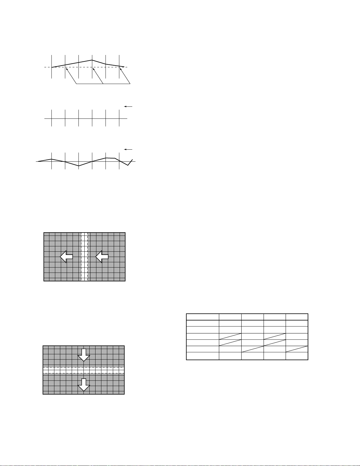
2nd step
Adjust so that the vertical lines become straight, taking care to
preserve proper screen information volume and the linearity.
Adjust the right half of the screen first, then the left half.
(See 3.4.)
4th step
Repeat 2nd and 3rd steps to take total balance. Then the adjustment for the green is completed.
To return from the fine adjustment mode to the coarse adjustment
mode, press the MENU key once, then the DOT key.
Note: When the MENU key is pressed to quit MANUAL
CONVERGENCE mode, the display will be unstable for
several seconds. This is because the adjustment data are
being written to the EEPROMs, and is not a malfunction.
Do not perform any operation (power on/off, or pressing
keys on the remote control unit or on the main unit, etc.)
during this period, because doing so may affect your
adjustment data.
Right half : Adjust from the edge toward the center.
Left half : Adjust from the center toward the edge.
3rd step
Adjust so that the horizontal lines become straight. Adjust the
upper half of the screen first, then the lower half. (See 3.4.)
Upper half : Adjust from the edge toward the center.
Lower half : Adjust from the center toward the edge.
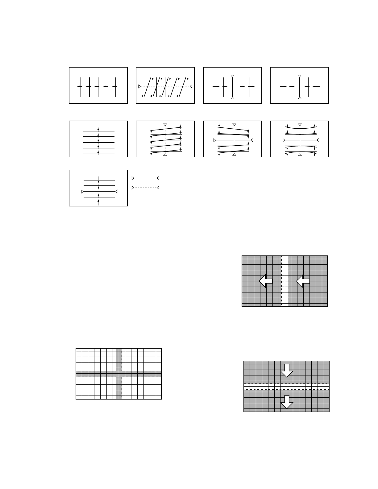
3.5 Coarse Adjustment of the Red
After the green adjustment is completed, quit MANUAL
CONVERGENCE mode by pressing the MENU or MUTING
key, then press the DOT key three times to enter OFFSET
CONVER. MODE 3.
Select adjustment items for RH and RV, and roughly correct
distortion to converge with the green. Adjustment is required for
each screen mode
For adjustable items of the red and the blue, see the following
table.
Numeric Key RH RV BH BV
0 STATIC STATIC STATIC STATIC
1 SKEW SKEW SKEW SKEW
4 KEY KEY
6 PIN PIN
7 LIN LIN
8 SIZE SIZE SIZE SIZE
210
• Pattern for each adjustment item
PRO-610HD, PRO-510HD, SD-582HD5, SD-532HD5
RH
BH
RV
BV
Key No.
STATIC
Key No.
STATIC
Key No.
SIZE
`
`
8
Key No.
SKEW
Key No.
SKEW
1
1
= Fixed position
Key No.
LIN
Key No.
7
4
KEY
Note 1: When the red CRT is replaced, or when the deflection
yoke for the red is replaced, prior to adjustment, tune the
center of the image to the center of the screen by turning
the centering magnet.
Note 2: When the CONVER. AMP Assy or DIGITAL CONV. Assy
is replaced, make coarse adjustment as shown in 3.5
above.
Key No.
SIZE
Key No.
PIN
8
6
3.6 Fine-adjustment of the Red
To fine-adjust the red, press the SET/ENTER key to enter
MANUAL CONVERGENCE mode. Repeat the coarse
adjustment described in "3.5 Coarse Adjustment of the Red" if
necessary. Make adjustment for each SCREEN mode, and
eliminate distortion to converge with the green.
3.6.1
Press the SET/ENTER key to enter MANUAL CONVERGENCE
mode, and make adjustment in the same manner as with the green.
First, adjust the vertical and horizontal the red lines at the center
of the screen so that they converge with the green center lines.
3.6.2
Adjust the red vertical lines so that they converge with the green
vertical lines. Proceed to adjustment of the right half of the
screen, then the left half. Adjustment should be done from the
part where convergence is greatly dislocated.
3.6.3
Adjust the red horizontal lines so that they converge with the
green horizontal lines. Proceed to adjustment of the upper half of
the screen, then the lower half. Adjustment should be done from
the part where convergence is greatly dislocated.
3.6.4
Repeat the adjustments described in 3.6.2 and 3.6.3 so that all the
red vertical and horizontal lines converge with the green lines.
(Completion of one screen mode)
211
PRO-610HD, PRO-510HD, SD-582HD5, SD-532HD5
3.6.5
Repeat procedures 3.6.2 through 3.6.4 for the other screen modes.
(Completion of the red adjustment)
3.7 Coarse Adjustment and Fine Adjust ment of the Blue
Make coarse and fine-adjustments of the blue in the same manner
as with the red, described in 3.5 and 3.6.
3.8 Confirmation of Adjustment
After the green, red, and blue adjustments are finished, check
convergence errors with the patterns for all three colors on the
monitor.
Check the patterns in all SCREEN modes, and if any error in
convergence is recognized, readjust convergence in MANUAL
CONVER. mode.
Note: Be sure NOT to change the green pattern during readjustment.
IMPORTANT!
(1) When all the adjustments are completed, or when adjustment
should be temporarily interrupted, adjustment data must be
written to the EEPROM, in the following manner:
When all the adjustments are completed, or to interrupt
adjustment, press the MENU key to quit Convergence
Adjustment mode. The display will be unstable for several
seconds, but this is because the data are being written to the
EEPROM. Wait without doing anything until the display
becomes stable, which means writing of data to the EEPROM is
finished.
If the power of the TV is turned off (standby) during Convergence
Adjustment mode (coarse and fine-adjustments), turn on the TV,
enter FACTORY mode, and enter Convergence Adjustment
mode by pressing the SET/ENTER key. Then press the MENU
key. The data will be written to the EEPROM as described above.
(2) Do NOT turn off the main power during or after convergence
adjustment.
If you do so, the adjusted data may be lost. If the data are lost,
you must make all the adjustments again.
(3) When the CENTER POINT (test cross) or MULTI-POINT (user
convergence) adjustments have been made by a user, and if the
unit enters FACTORY Convergence Adjustment mode (with the
DOT and SET/ENTER keys), the user's adjustment data will be
all cleared and returned to the factory-preset values.
Be sure NOT to enter this Convergence Adjustment mode except
when a repair related to convergence or a repair that requires
convergence adjustment later, is needed.
If you inadvertently enter Convergence Adjustment mode,
readjust the convergence.
7
White Balance Adjustment
7
Contrast Adjustment
-1
Start
TV/
CBL
DVD
VCR
DTV
/SAT
/LD
ON/OFF
POWER
TVTVDTV
INPUT
1 2 3 4
SELECTSEARCH
SPLIT
SCREEN
FREEZE
MODE
ANT
DTV
AUDIO
1
2 3
47586
0
¢
CH
RETURN
CH
MUTING
4
EDIT/
TV/SAT/DVD
LEARN
MENU
SOURCE
5
POWER
POWER
SET/
2 3
ENTER
8
∞
FAVORITE CH
173¡
RECEIVER
POWER
INPUT
PROJECTION MONITOR RECEIVER
REMOTE CONTROL UNIT
SUB CH
DISPLAY
9
CH
ENTER
VOL
DTV/DVD TOP
MENU
DTV/SAT
GUIDE
DTV/(SAT)
INFO
VCR REC
VOLVOL
Î
1st FAC
3
"Color Bar"
Adjust the screen to optimum condition.
At the TP-BK of the B CRT DRIVE Assy, check that the signal
is shaped as shown below.
ADJUSTMENT OFFSET
"Normal video signal"
CONTR
Shapely waveform
Shapeless waveform
Saturated
After the STD adjustment is complete, adjust the COMP 15K, COMP 31K, 33K RGB, COLOR TEMP FILM or STD and COLOR
TEMP B&W for STD.
212

PRO-610HD, PRO-510HD, SD-582HD5, SD-532HD5
7
POWER
1 2 3 4
SPLIT
SCREEN
MODE
DTV
AUDIO
1
47586
CH
EDIT/
LEARN
SOURCE
POWER
POWER
8
173¡
POWER
PROJECTION MONITOR RECEIVER
REMOTE CONTROL UNIT
White Balance Adjustment
-2
TV/
DTV
¢
4
2 3
Start
CBL
DVD
VCR
/SAT
/LD
ON/OFF
TVTVDTV
INPUT
SELECTSEARCH
SUB CH
FREEZE
ANT
(DOWN)
DISPLAY
2 3
9
∞
CH
ENTER
0
CH
RETURN
VOL
MUTING
DTV/DVD TOP
TV/SAT/DVD
MENU
MENU
DTV/SAT
5
GUIDE
SET/
ENTER
DTV/(SAT)
INFO
∞
VCR REC
FAVORITE CH
RECEIVER
INPUT
VOLVOL
Î
1
∞
3
SUB CH
2
CH
ENTER
4
1st FAC
STD OFFSET
Telop: Blue
: STD OFFSET
: COMPORNENT 31, 33K
: COMPORNENT 15K
: RGB
DTV/(SAT)
INFO
5
: FILM for STD
DTV/DVD TOP
MENU
6
: B & W for STD
a
COLOR
This mode is to set the standard picture quality for a normal picture.
< Picture Quality >
CH
1
2 3
b
-24
Data value
b
4
8 9
0
< Data value >
VOL
or
ab
1
: COLOR (–64 to 63)
2
: TINT (–64 to 63)
: CONTRAST (–64 to 63)
3
: BRIGHT (–128 to 127)
4
8
: DRV-R (–64 to 63)
9
: DRV-B (–64 to 63)
0
: CUT-R (–128 to 127)
: CUT-G (–128 to 127)
CH
: CUT-B (–128 to 127)
TV/
CBL
DVD
VCR
DTV
/SAT
/LD
ON/OFF
POWER
TVTVDTV
INPUT
1 2 3 4
SELECTSEARCH
SPLIT
SUB CH
SCREEN
FREEZE
MODE
ANT
DTV
DISPLAY
AUDIO
1
2 3
47586
0
¢
CH
RETURN
CH
MUTING
4
EDIT/
TV/SAT/DVD
LEARN
MENU
SOURCE
5
POWER
POWER
SET/
2 3
ENTER
8
∞
FAVORITE CH
173¡
RECEIVER
POWER
INPUT
PROJECTION MONITOR RECEIVER
REMOTE CONTROL UNIT
0
8 9
9
CH
ENTER
VOL
DTV/DVD TOP
MENU
DTV/SAT
GUIDE
DTV/(SAT)
INFO
VCR REC
VOLVOL
Î
CH
or
Color bar signal
without color signal.
Adjust the DRV-R and DRV-B
so that the bright part of the
screen becomes white.
Adjust the CUT-R and CUT-B
so that the dark part of the
screen becomes gray.
Do not move the screen VR.
Cut-G can be adjusted with little
movement in STD OFFSET mode.
Note :
Not all adjustments described above can be made for COLOR TEMP FILM for STD and COLOR TEMP B&W for STD.
Refer to the following adjustment procedure.
8
9
0
: DRV-R
: DRV-B
: CUT-R
: CUT-B
: CUT-G
213
PRO-610HD, PRO-510HD, SD-582HD5, SD-532HD5
Adjustment Procedure of White Balnce
OFFSET Data Table
COLOR
TEMP
Setting
User
Mode
Input
STD NEWS LIVE FILM STD FILM MOVIE B&W STD B&W MOVIE NEWS LIVE FILM B&W
IJKL M V X βγYZ
MOVIE
E
TV
COMPORNENT 15KCCOMPORNENT 31K 33K
B
Signal
Adjustments are required for A, C, D, T, L, and V in the table above. Data in other parts are fixed. (I="0")
Proceed with the adjustments in the following order:
Adjustment Direct key Picture quality data on the screen
(1) STD OFFSET DOWN A Adjustment of all standard picture qualities
(2) COMPONENT 15K SUB CH- A+C Adjustment of C
(3) COMPONENT 31, 33K SUB CH+ A+D Adjustment of D
(4) RGB CH ENTER A+T Adjustment of T
(5) FILM for STD INFO A+L Adjustment of L
(6) B&W for STD DTV MENU A+V Adjustment of V
Without RGB Input RGB Input
GAME
F
RGB
D
T
STD OFFSET
A
Make adjustment only for items
described as ADJ in the following
table.
Do NOT change other data.
Other data are adjusted in factory
shipment by Fix data of the following
table . (refer to page 215.)
• First, perform "(1) STD OFFSET", then perform adjustments (2), (3) and (4) so that the same picture
quality (color temperature) as achieved in (1) is obtained.
• In adjustment (5), make the whole picture more reddish than in (1), and in adjustment (6), make it more reddish.
• When readjusting, once "(1) STD OFFSET" is adjusted, the data for other input signals (component, etc.) revert to the factory-preset
values, in principle.
• After the adjustment of STD OFFSET is completed, check other picture quality modes by switching color temperatures and signals.
It is OK if picture quality does not deviate greatly when input signal is changed (composite, component 15K, etc.).
Furthermore, it is OK if color temperature changes when color remperarure is changed.
With this model, five color temperature switching modes are provided. In FILM and B&W modes, a white part appears to be reddish in
general because of their color temperature settings.
7
Color/Tint Adjustment
-3
Start
1st FAC
"Color Bar"
TV/
CBL
DTV
/SAT
POWER
TVTVDTV
INPUT
1 2 3 4
SPLIT
SCREEN
MODE
ANT
DTV
AUDIO
1
47586
¢
RETURN
CH
MUTING
4
EDIT/
TV/SAT/DVD
LEARN
MENU
SOURCE
POWER
POWER
2 3
ENTER
8
FAVORITE CH
173¡
RECEIVER
POWER
INPUT
PROJECTION MONITOR RECEIVER
REMOTE CONTROL UNIT
DVD
VCR
/LD
ON/OFF
SELECTSEARCH
SUB CH
FREEZE
DISPLAY
2 3
1
9
CH
ENTER
0
CH
VOL
DTV/DVD TOP
2
MENU
DTV/SAT
5
GUIDE
SET/
DTV/(SAT)
INFO
∞
VCR REC
VOLVOL
Î
ADJUSTMENT OFFSET
TINT
Adjust 1 COLOR and 2 TINT so that
the color-bar is set in the proper color
saturation and the tint.
Do not adjust the RGB, COLOR TEMP FILM and B&W.
214
PRO-610HD, PRO-510HD, SD-582HD5, SD-532HD5
OFFSET DATA (VIDEO)
ADJ :Adjustment item
The numerical value is shipping a set value in the factory.
A set value is data of 1999.11 present provinces.
DIRECT KEY
OFFSET MODE MODEL
KEY
ADJ NAME
DOWN
STD OFFSET A
1 COLOR ADJ ADJ
2 TINT ADJ ADJ
3 CONTRAST ADJ ADJ
4 BRIGHT ADJ ADJ
5 SHARPNESS 0 0
6 DETAIL –50 –15
7 S. V. M 0 0
8 R DRV ADJ ADJ
9 B DRV ADJ ADJ
0 R CUT ADJ ADJ
CH+ G CUT ADJ ADJ
CH– B CUT ADJ ADJ
SUB CH –
COMPONENT 15K C
1 COLOR ADJ ADJ
2 TINT ADJ ADJ
3 CONTRAST ADJ ADJ
4 BRIGHT 0 0
5 SHARPNESS 0 0
6 DETAIL 0 0
7 S. V. M 0 0
8 R DRV ADJ ADJ
9 B DRV ADJ ADJ
0 R CUT ADJ ADJ
CH+ G CUT ADJ ADJ
CH– B CUT ADJ ADJ
SUB CH+
COMPONENT 31, 33K D
1 COLOR ADJ ADJ
2 TINT ADJ ADJ
3 CONTRAST ADJ ADJ
4 BRIGHT 0 0
5 SHARPNESS –20 –20
6 DETAIL 92 127
7 S. V. M 0 0
8 R DRV ADJ ADJ
9 B DRV ADJ ADJ
0 R CUT ADJ ADJ
CH+ G CUT ADJ ADJ
CH– B CUT ADJ ADJ
RED
TV OFFSET B
1 COLOR –10 –10
2 TINT 0 0
3 CONTRAST 0 0
4 BRIGHT 0 0
5 SHARPNESS 0 0
PRO-610HD SD-582HD5
PRO-510HD SD-532HD5
DIRECT KEY
OFFSET MODE MODEL
KEY
BLUE (cyclically)
MOVIE OFFSET E
1 COLOR –11 –30
2 TINT –13 –11
3 CONTRAST –27 –14
4 BRIGHT 0 0
5 SHARPNESS –20 –20
6 DETAIL 30 30
8 R DRV 1 –2
9 B DRV 4 6
0 R CUT –5 8
CH+ G CUT –3 5
CH– B CUT –3 4
GAME OFFSET F
1 COLOR 0 0
2 TINT 0 0
3 CONTRAST –43 –28
4 BRIGHT 0 0
5 SHARPNESS –35 –35
6 DETAIL 0 0
8 R DRV 0 3
9 B DRV 8 7
0 R CUT 4 13
CH+ G CUT 7 13
CH– B CUT 3 11
CH ENTER
RGB OFFSET T
3 CONTRAST ADJ ADJ
4 BRIGHT ADJ ADJ
8 R DRV ADJ ADJ
9 B DRV ADJ ADJ
0 R CUT ADJ ADJ
CH+ G CUT ADJ ADJ
CH– B CUT ADJ ADJ
INFO
COLOR TEMP FILM for STD L
3 CONTRAST ADJ ADJ
8 R DRV ADJ ADJ
9 B DRV ADJ ADJ
0 R CUT ADJ ADJ
CH+ G CUT ADJ ADJ
CH– B CUT ADJ ADJ
DTV MENU
COLOR TEMP B&W for STD V
3 CONTRAST ADJ ADJ
8 R DRV ADJ ADJ
9 B DRV ADJ ADJ
0 R CUT ADJ ADJ
CH+ G CUT ADJ ADJ
CH– B CUT ADJ ADJ
ADJ NAME
PRO-610HD SD-582HD5
PRO-510HD SD-532HD5
DIRECT KEY
OFFSET MODE MODEL
KEY
ADJ NAME
GREEN (cyclically)
COLOR TEMP NEWS for STD J
3 CONTRAST –6 –6
8 R DRV –1 –1
9 B DRV 16 16
0 R CUT 3 3
CH+ G CUT 3 3
CH– B CUT 1 1
COLOR TEMP LIVE for STD K
3 CONTRAST –1 –1
8 R DRV –5 –5
9 B DRV 7 7
0 R CUT 2 2
CH+ G CUT 3 3
CH– B CUT 1 1
COLOR TEMP FILM for MOVIE M
3 CONTRAST 0 0
8 R DRV 9 1
9 B DRV –10 –15
0 R CUT –1 0
CH+ G CUT 0 0
CH– B CUT 1 0
COLOR TEMP B&W for MOVIE X
3 CONTRAST –1 0
8 R DRV 15 6
9 B DRV –17 –22
0 R CUT 1 1
CH+ G CUT 2 2
CH– B CUT 3 1
GREEN (cyclically)
COLOR TEMP NEWS for RGB β
3 CONTRAST –6 –6
4 BRIGHT 0 0
8 R DRV –1 –1
9 B DRV 16 16
0 R CUT 3 3
CH+ G CUT 3 3
CH– B CUT 1 1
COLOR TEMP LIVE for RGB γ
3 CONTRAST –1 –1
4 BRIGHT 0 0
8 R DRV –5 –5
9 B DRV 7 7
0 R CUT 2 2
CH+ G CUT 3 3
CH– B CUT 1 1
COLOR TEMP FILM for RGB Y
3 CONTRAST –1 –1
4 BRIGHT 0 0
8 R DRV 14 14
9 B DRV –10 –10
0 R CUT 1 1
CH+ G CUT 3 3
CH– B CUT 4 4
COLOR TEMP B&W for RGB Z
3 CONTRAST –1 –1
4 BRIGHT 0 0
8 R DRV 18 18
9 B DRV –17 –17
0 R CUT –1 –1
CH+ G CUT 2 2
CH– B CUT 4 4
PRO-610HD SD-582HD5
PRO-510HD SD-532HD5
215
PRO-610HD, PRO-510HD, SD-582HD5, SD-532HD5
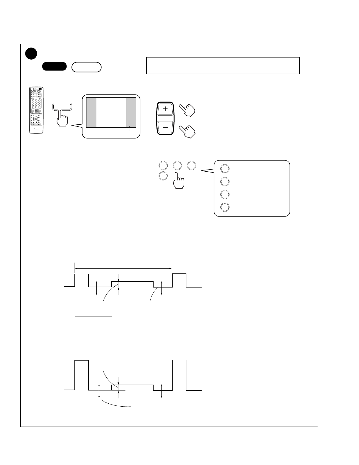
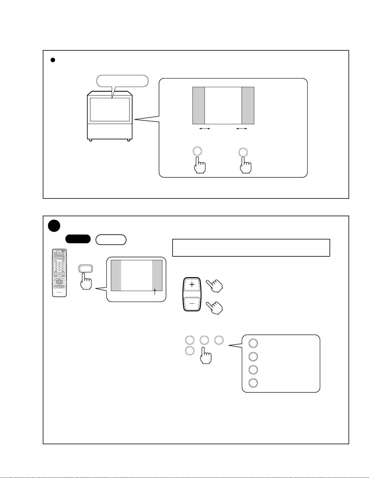
8
Panel Adjustment
• Mode for adjusting the brightness, contrast LEFT and RIGHT of the
gray part (panel) of the 4:3 normal screen.
<Data value section>
VOL
or
<Adjustment item section>
TV/
CBL
VCR
DTV
/SAT
POWER
TVTVDTV
INPUT
1 2 3 4
SPLIT
SCREEN
MODE
ANT
DTV
AUDIO
1
2 3
47586
0
¢
CH
RETURN
CH
MUTING
4
EDIT/
TV/SAT/DVD
LEARN
MENU
SOURCE
5
POWER
POWER
SET/
2 3
ENTER
8
∞
FAVORITE CH
173¡
RECEIVER
POWER
INPUT
PROJECTION MONITOR RECEIVER
REMOTE CONTROL UNIT
Start
DVD
/LD
ON/OFF
SELECTSEARCH
SUB CH
FREEZE
DISPLAY
9
CH
ENTER
RETURN
VOL
DTV/DVD TOP
MENU
DTV/SAT
GUIDE
DTV/(SAT)
INFO
VCR REC
VOLVOL
Î
CH
1st FAC
ADJUSTMENT
Telop : White
PANEL
BRIGHT
Data value
–24
1423
1
: BRIGHT (–64 to 63)
: CONTRAST (–64 to 63)
2
: LEFT (–128 to 127)
3
: RIGHT (–128 to 127)
4
Procedures
1 Send the black-burst signal to the INPUT 1 connector.
Enter Adjustment mode by following the procedures described above.
2 With BRIGHT, adjust the gray part (panel) of the screen.
By observing TP5151 of the GREEN CRT DRIVE assembly with the oscilloscope, , adjust the brightness level which is low by 20V
from Black level of the main screen.
31.7µS
210V
Approx. 20V
GND
3 Switch the input signal to a 100%-white signal.
Adjust the panel part and the main screen with CONTRAST.
Observe the same site as described in Step 2 above, and adjust the amplitude of the luminosity.
Main screen
(black)
Panel part: The level of this part changes with the BRIGHT data.
Adjust so that the level of the luminosity of the panel and that of the main screen become the same.
Approx. 0V
Main screen
(white)
The level of the panel part changes with the CONTRAST data.
The level of the main screen heightens or lowers in the reverse direction.
216
PRO-610HD, PRO-510HD, SD-582HD5, SD-532HD5
Size Adjustment of the Panel Part of the 4:3 Normal Screen
"Monoscope signal"
Set the LEFT data
item to 91 ± 2%.
Set the RIGHT data
item to 91 ± 2%.
3
9
Panel Adjustment for DTV (PRO-610HD, PRO-510HD ONLY)
TV/
CBL
DTV
/SAT
POWER
TVTVDTV
INPUT
1 2 3 4
SPLIT
SCREEN
MODE
ANT
DTV
AUDIO
1
47586
¢
RETURN
CH
MUTING
4
EDIT/
TV/SAT/DVD
LEARN
MENU
SOURCE
POWER
POWER
SET/
2 3
ENTER
8
FAVORITE CH
173¡
RECEIVER
POWER
INPUT
PROJECTION MONITOR RECEIVER
REMOTE CONTROL UNIT
Start
DVD
VCR
/LD
ON/OFF
SELECTSEARCH
SUB CH
FREEZE
DISPLAY
2 3
9
CH
ENTER
0
CH
VOL
DTV/DVD TOP
MENU
DTV/SAT
5
GUIDE
DTV/(SAT)
INFO
∞
VCR REC
VOLVOL
Î
ON/OFF
DTV
1st FAC
ADJUSTMENT
Telop : Yellow
DTV PANEL
BRIGHT
Data value
–24
• Mode for adjusting the brightness, contrast LEFT and RIGHT of the
gray part (panel) of the 4:3 normal screen of the DTV tuner.
<Data value section>
VOL
or
4
<Adjustment item section>
1423
Note :
• Adjustment required only for the PRO-510HD/610HD to which a BIB (SH-D07/D09) can be connected.
• No adjustment is needed for the SD-582HD5/532HD5.
• The adjustment procedures are the same as those described in "8 Panel Adjustment," except for the following:
• Send the black burst of the HD signal to the INPUT 1 connector.
• Send a 70%-white (if not available, 100%-white) HD signal to the INPUT 1 connector.
• As for the size adjustment, adjust so that the panel size becomes the same as that adjusted in "8 Panel Adjustment."
1
: BRIGHT (–64 to 63)
: CONTRAST (–64 to 63)
2
: LEFT (–128 to 127)
3
: RIGHT (–128 to 127)
4
217
 Loading...