

Page 1

Page 2
The exclamation point within an equilateral
triangle is intended to alert the user to the
presence of important operating and
maintenance (servicing) instructions in the
literature accompanying the appliance.
The lightning flash with arrowhead symbol, within an
equilateral triangle, is intended to alert the user to the
presence of uninsulated "dangerous voltage" within the
product's enclosure that may be of sufficient magnitude
to constitute a risk of electric shock to persons.
CAUTION:
TO PREVENT THE RISK OF ELECTRIC SHOCK, DO
NOT REMOVE COVER (OR BACK). NO USERSERVICEABLE PARTS INSIDE. REFER SERVICING
TO QUALIFIED SERVICE PERSONNEL.
CAUTION
RISK OF ELECTRIC SHOCK
DO NOT OPEN
IMPORTANT
D3-4-2-1-1_En-A
Read these instructions.
Keep these instructions.
Heed all warnings.
Follow all instructions.
Do not use this apparatus near water.
Clean only with dry cloth.
Do not block any ventilation openings. Install in
accordance with the manufacturer’s instructions.
Do not install near any heat sources such as
radiators, heat registers, stoves, or other apparatus
(including amplifiers) that produce heat.
Do not defeat the safety purpose of the polarized or
grounding-type plug. A polarized plug has two
blades with one wider than the other. A grounding
type plug has two blades and a third grounding
prong. The wide blade or the third prong are
provided for your safety. If the provided plug does
not fit into your outlet, consult an electrician for
replacement of the obsolete outlet.
Protect the power cord from being walked on or
pinched particularly at plugs, convenience
receptacles, and the point where they exit from the
apparatus.
1)
2)
3)
4)
5)
6)
7)
8)
9)
10)
Only use attachments/accessories specified by the
manufacturer.
Use only with the cart, stand, tripod, bracket, or
table specified by the manufacturer, or sold with the
apparatus. When a cart is used, use caution when
moving the cart/apparatus combination to avoid
injury from tip-over.
Unplug this apparatus during lightning storms or
when unused for long periods of time.
Refer all servicing to qualified service personnel.
Servicing is required when the apparatus has been
damaged in any way, such as power-supply cord or
plug is damaged, liquid has been spilled or objects
have fallen into the apparatus, the apparatus has
been exposed to rain or moisture, does not operate
normally, or has been dropped.
P1-4-2-2_En
11)
12)
13)
14)
IMPORTANT NOTICE – THE SERIAL NUMBER FOR THIS EQUIPMENT IS LOCATED IN THE REAR. PLEASE
WRITE THIS SERIAL NUMBER ON YOUR ENCLOSED WARRANTY CARD AND KEEP IN
A SECURE AREA. THIS IS FOR YOUR SECURITY.
WARNING: Handling the cord on this product or cords
associated with accessories sold with the product will
expose you to chemicals listed on proposition 65 known
to the State of California and other governmental
entities to cause cancer and birth defect or other
reproductive harm.
Wash hands after handling
D36-P4-A_En
D1-4-2-6-1_En
Page 3

TABLE OF CONTENTS
Congratulations on purchasing a Pioneer Elite KURO monitor.
At Pioneer, everything we do is designed to alter perceptions, to shatter expectations, to change the way people feel about
sight and sound.
This exclusive series of Elite KURO monitors does just that. The result of a special limited run created for the
entertainment purist, this monitor was designed to excel under the most demanding situations, to be fully customizable
to the most particular tastes and to transcend the ordinary.
We are proud to incorporate this philosophy of exceptional quality, state-of-the-art design and meticulous engineering to
make the Elite KURO monitor one of the finest in the world and immerse you into one of the best entertainment
experiences possible.
Please spend some time reading through this owner’s guide and manual to learn about the many features and benefits
that make this Elite KURO monitor unique. We hope you enjoy the experience of owning an Elite KURO and invite you to
enter a new world of seeing and hearing like never before.
TABLE OF CONTENTS
1 Introduction to the Flat Panel Displays..................................................................................................6
1.1 Flat Panel Display Shipment Checklist ........................................................................................................................... 6
1.2 Control Options: Get to Know Your Flat Panel Display .................................................................................................. 7
1.2.1 Control Buttons and More on the Flat Panel Display............................................................................................ 7
1.2.2 Operating the Remote Control............................................................................................................................... 8
1.2.3 Buttons on the Remote Control ............................................................................................................................ 10
2 Install Your Flat Panel Display ..............................................................................................................12
2.1 Use the Optional Table Top Stand (Stand) or Equivalent Items.................................................................................. 12
2.2 Use the Optional Brackets or Equivalent Items ........................................................................................................... 13
2.2.1 Check the Location for Suitability ......................................................................................................................... 14
2.2.2 Lift and/or Move Your Panel (the How To’s)......................................................................................................... 14
2.2.3 Mount the Flat Panel Display ................................................................................................................................ 15
2.3 Connect to Other Devices (DVR, Receiver, BDR, etc.)................................................................................................ 17
2.4 Connect the Power Cord to the Panel........................................................................................................................... 19
2.5 Route then Bundle the Power Cord and Cables .......................................................................................................... 19
3 Basic Operations.....................................................................................................................................21
3.1 Turn the Flat Panel Display ON / OFF ........................................................................................................................... 21
3.2 Program Your Flat Panel Display................................................................................................................................... 22
3.2.1 Choose an Input Source ........................................................................................................................................ 22
3.2.2 Explore the Home Menu ........................................................................................................................................ 22
3.2.3 Use the Simplified User Menu .............................................................................................................................. 23
3.2.4 Assign a Language................................................................................................................................................. 24
4 Basic Picture Adjustment.......................................................................................................................25
4.1 Adjust the Picture Quality .............................................................................................................................................. 25
4.1.1 Adjust the Picture for Your Room Lighting .......................................................................................................... 25
4.1.2 General Picture (Video) Adjustment ..................................................................................................................... 25
4.1.3 Compare Images When Adjusting the Picture....................................................................................................27
4.2 Smart Starts for New Owners........................................................................................................................................ 28
4.2.1 Extend Your Panel Life ........................................................................................................................................... 28
4.2.2 Adjust the Power Indicator Brightness ................................................................................................................ 28
4.2.3 Set Input Priority..................................................................................................................................................... 28
4.2.4 Turn On the Image Orbiter .................................................................................................................................... 29
4.2.5 Trigger the Screen-Saving Video Pattern Periodically ........................................................................................ 29
4.2.6 Activate Energy Save to Reduce Power Usage.................................................................................................... 29
4.2.7 Turn On the Sleep Timer........................................................................................................................................ 30
En
3
Page 4

TABLE OF CONTENTS
5 Additional Picture Adjustment Options............................................................................................... 31
5.1 Choose an AV Option (Video, Game, etc.).....................................................................................................................31
5.1.1 AV Source through the Remote Control...............................................................................................................31
5.1.2 Choose an AV Source through the Home Menu .................................................................................................32
5.1.3 Choose a PC Source...............................................................................................................................................32
5.1.4 Set the Panel to Recognize a Game Console .......................................................................................................32
5.2 Adjust Specific Picture Elements ..................................................................................................................................33
5.2.1 Choose a Screen Size (Automatically or Manually).............................................................................................33
5.2.2 Correct the Picture for an AV or PC Source .........................................................................................................35
5.3 Assign Advanced Picture Functions .............................................................................................................................36
5.3.1 Adjust for Screen Masking (black bars on sides) ................................................................................................36
5.3.2 Select a Color Temperature Level..........................................................................................................................37
5.3.3 Adjust the Image Gradation Characteristics (Gamma).......................................................................................38
5.3.4 Select a PureCinema Level for High Quality Image.............................................................................................38
5.3.5 Select an Intelligent Mode Option.........................................................................................................................39
5.3.6 Select the Picture Detail Options ..........................................................................................................................40
5.3.7 Use CTI and Color Space .......................................................................................................................................40
5.3.8 Use the Color Management...................................................................................................................................41
5.3.9 Reduce Noise from the Image...............................................................................................................................41
5.3.10 Adjust Color Signals.............................................................................................................................................42
5.4 View in Multi-Screen .......................................................................................................................................................43
5.4.1 Split / Swap / Shift the Screen...............................................................................................................................43
5.4.2 Turn the Small Screen On/Off ...............................................................................................................................44
5.5 Freeze the Picture ...........................................................................................................................................................44
5.6 Manage the Power ..........................................................................................................................................................45
6 Use Other Equipment With Your Flat Panel Display ........................................................................... 46
6.1 Program the Remote Control to Operate Other Equipment........................................................................................46
6.1.1 Use the Learning Function ....................................................................................................................................46
6.1.2 Assign a Manufacturing Code to the Remote Control ........................................................................................47
6.1.3 Issue a Library Search for a Manufacturer Code.................................................................................................47
6.1.4 Clear Added Manufacturer Codes from the Remote Control .............................................................................48
6.1.5 Control a Pioneer Receiver ....................................................................................................................................48
6.1.6 Control a Cable (CBL) or Satellite (SAT) System..................................................................................................49
6.1.7 Control a Video Cassette Recorder (VCR) ............................................................................................................50
6.1.8 Control a DVD Player/DVR Recorder/BD Player..................................................................................................51
6.2 Apply Settings for Other Equipment..............................................................................................................................52
6.2.1 Apply Settings for an AV System...........................................................................................................................52
6.2.2 Apply Settings for a PC ..........................................................................................................................................53
6.3 Use HDMI Inputs.............................................................................................................................................................54
6.3.1 Enter an HDMI Input Name...................................................................................................................................54
6.3.2 Specify the HDMI Input Type .................................................................................................................................55
6.3.3 Specify a Digital HDMI Signal Type ......................................................................................................................55
6.4 Control Equipment with the Panel’s Remote Through HDMI .....................................................................................56
6.4.1 Control an AV System.............................................................................................................................................58
6.4.2 Control a Recorder .................................................................................................................................................59
6.4.3 Control a Player.......................................................................................................................................................59
6.4.4 Add an AV Amp or a BD Player.............................................................................................................................60
6.5 Specific KURO LINK Commands ..................................................................................................................................61
6.5.1 Play Source Sound Using an HDMI Command...................................................................................................61
6.5.2 Turn OFF the Power With an HDMI Command ...................................................................................................61
6.5.3 Turn ON the Power With an HDMI Command.....................................................................................................61
6.5.4 Test the Power Control (On/Off) ............................................................................................................................62
6.6 Connect a Game Console or Camcorder ......................................................................................................................62
6.7 Use the IR REPEATER OUT ............................................................................................................................................62
6.8 Connect to a Network .....................................................................................................................................................63
6.8.1 IP Control Setting ...................................................................................................................................................64
4
En
6.8.2 Use the Web Control System.................................................................................................................................65
Page 5

TABLE OF CONTENTS
6.9 Assign a Serial Number ................................................................................................................................................. 69
6.9.1 Assign an ID Number ............................................................................................................................................ 69
6.9.2 Assign a Baud Rate................................................................................................................................................ 70
6.10 Select the Integrator Mode .......................................................................................................................................... 70
6.10.1 Explore the Integrator Mode Menus ................................................................................................................... 71
7 Helpful Information ...............................................................................................................................75
7.1 Frequently Asked Questions (FAQs) ............................................................................................................................. 75
7.2 Cleaning Methods........................................................................................................................................................... 76
7.3 Troubleshooting & Service Information......................................................................................................................... 77
8 Cautions and Warnings..........................................................................................................................80
8.1 Installation Details .......................................................................................................................................................... 80
8.2 Physical Location & Temperature Considerations....................................................................................................... 80
8.3 Usage Guidelines ............................................................................................................................................................ 80
8.4 Signal Interference or Noise .......................................................................................................................................... 81
8.5 Phosphor Properties....................................................................................................................................................... 81
8.6 Image Information Including Retention & After-Image Lag ........................................................................................81
8.7 Prevent Burning .............................................................................................................................................................. 82
8.8 Safety Precautions.......................................................................................................................................................... 83
8.9 Legal Notices................................................................................................................................................................... 83
8.9.1 Safety....................................................................................................................................................................... 83
8.9.2 Radio Interference.................................................................................................................................................. 84
9 Appendix ................................................................................................................................................85
9.1 Manufacturer Codes to Program into the Remote Control......................................................................................... 85
9.1.1 Cable........................................................................................................................................................................ 85
9.1.2 Satellite.................................................................................................................................................................... 86
9.1.3 VCR .......................................................................................................................................................................... 88
9.1.4 BDP (Blu-ray) .......................................................................................................................................................... 91
9.1.5 DVD-R...................................................................................................................................................................... 92
9.1.6 DVD.......................................................................................................................................................................... 93
9.1.7 LD.............................................................................................................................................................................95
9.2 Video/PC Signals (HDMI/DVI/Component/min D-Sub/Composite) ........................................................................... 96
9.2.1 INPUT 1 (Video Signals)......................................................................................................................................... 96
9.2.2 INPUT 2 (Component)/INPUT 3 (D-Sub) - Video Signals (Analog)..................................................................... 96
9.2.3 INPUT 4 (DVI)/INPUT 5 through 8 (HDMI) - Video Signals (Digital)................................................................... 97
9.2.4 INPUT 3 (D-Sub) - PC Signals (Analog) ................................................................................................................ 98
9.2.5 INPUT 4 (DVI)/INPUT 5 through 8 (HDMI) - PC Signals (Digital) ....................................................................... 99
9.3 Specifications................................................................................................................................................................ 101
9.4 Trademarks.................................................................................................................................................................... 101
9.5 Glossary ......................................................................................................................................................................... 102
9.6 Index............................................................................................................................................................................... 104
En
5
Page 6
01
Introduction to the Flat Panel Displays
1 Introduction to the Flat Panel Displays
The Pioneer Flat Panel Display models include the 60-inch PRO-141FD and the 50-inch PRO-101FD (screen sizes
measured diagonally). Below is a list of all accessories shipped with your panel. If an item is missing, please
contact your dealer or our Service organization immediately. Service contact information is listed on the back of
this manual.
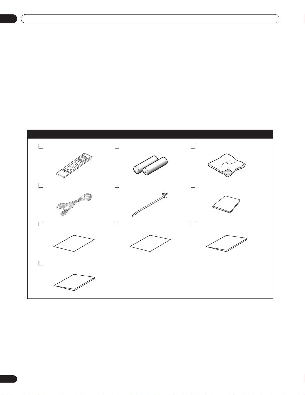
1.1 Flat Panel Display Shipment Checklist
In addition to the flat panel display, there are several accessories included to make installation quick and easy.
Please check contents before discarding or allowing your installer to discard any packing material.
Identify the accessories from the appropriate list below.
You will need a Philips screwdriver if removing or attaching the stand.
Shipped with both models
Remote Control Batteries for Remote (2) Cleaning Cloth
Power Cord (2 m/6.6 feet) Cable Clamps (4) Operating Instructions
Certificate of Authenticity Certificate Glossary Warranty Card
Specifications Sheet
6
En
Page 7
Introduction to the Flat Panel Displays
9
3
4 5
1 2
6
7 8
7
6
8
PRO-141FD
(Right side)
PRO-101FD
(Bottom of the rear panel)
1.2 Control Options: Get to Know Your Flat Panel Display
You can operate your flat panel display from the panel buttons or with the remote control. The following sections
provide button locations/operations for the panel and the remote control.
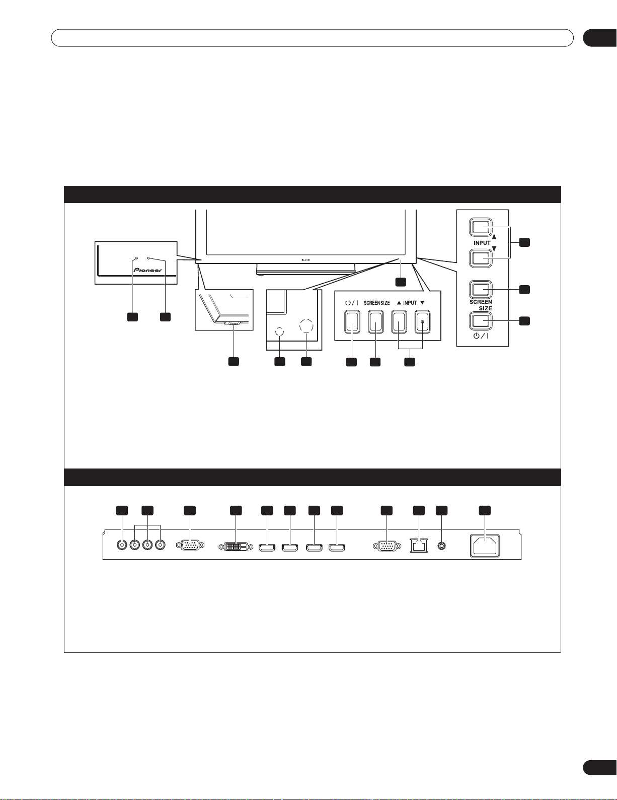
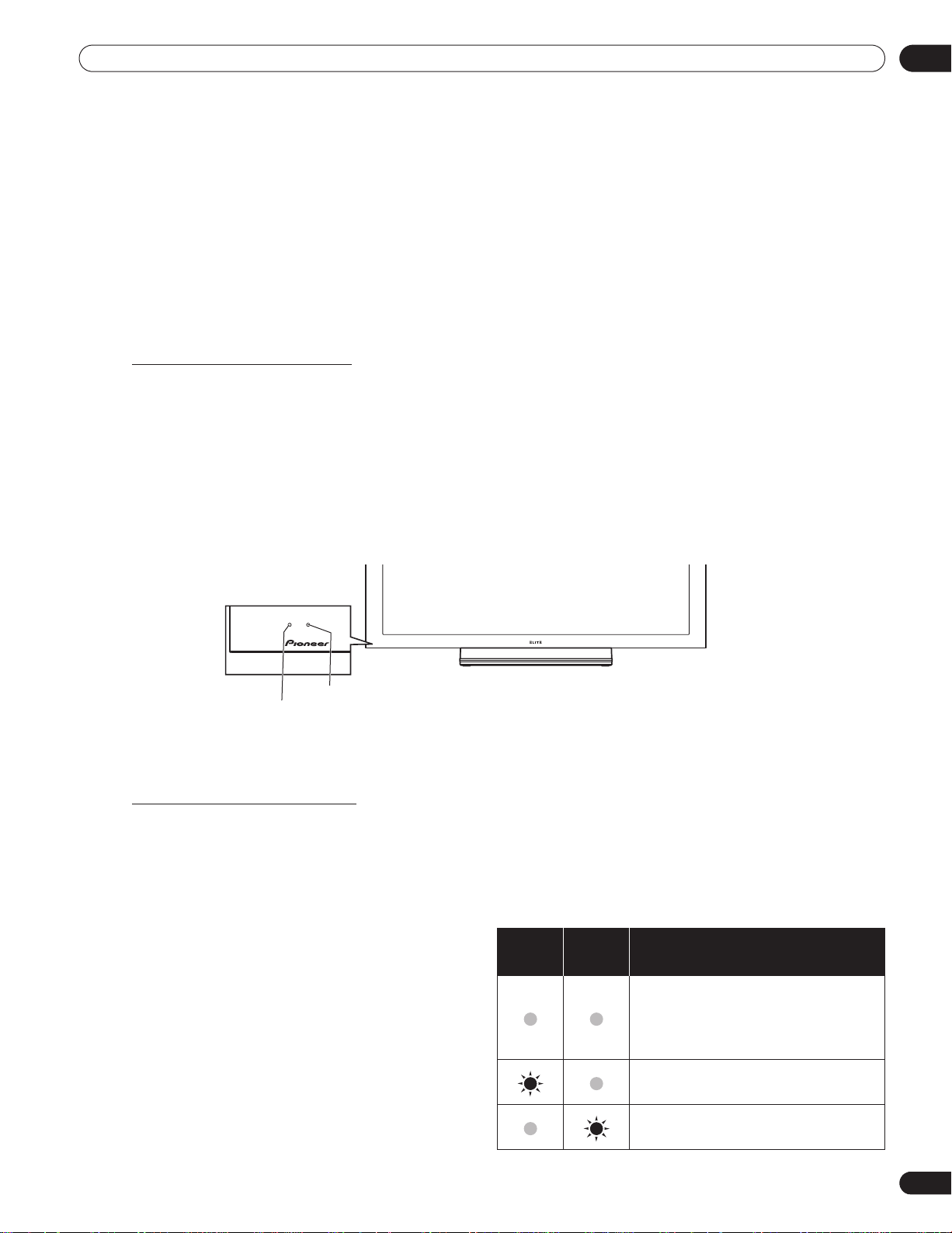
1.2.1 Control Buttons and More on the Flat Panel Display
Your flat panel display has buttons, indicators, and sensors on the lower front bezel with more buttons on the rear
panel. Refer to the drawings below for specific locations and functions. Or, to identify back ports and terminals
only, check the terminal position sheet located near the panel’s terminal compartment.
PRO-141FD/PRO-101FD: Face of Panel
01
1 - Power On indicator
2 - STANDBY indicator
3 - Power On () button
4 - Room Light sensor
5 - Remote Control sensor
Back of the Panel
(upper bank)
1 3 4 5 6 7 8 9 10 11 122
(from left to right)
1 - INPUT 1 terminal (Video)
2 - INPUT 2 terminals (Component, Y, C
3 - INPUT 3 terminal (Analog RGB)
4 - INPUT 4 terminal (DVI-D)
5 - INPUT 5 terminal (HDMI)
6 - INPUT 6 terminal (HDMI)
Terminals on the rear panel are common to both models.
B/PB
, CR/PR)
6 - STANDBY/ON button
7 - SCREEN SIZE button
8 - INPUT buttons
9 - Bezel (some call it the front frame)
7 - INPUT 7 terminal (HDMI)
8 - INPUT 8 terminal (HDMI)
9 - RS-232C terminal (for factory use)
10 - LAN terminal
11 - IR REPEATER OUT terminal
12 - AC In terminal
7
En
Page 8
01
When disposing of used batteries, please comply with
governmental regulations or environmental public institution’s
rules that apply in your country/area.
Introduction to the Flat Panel Displays
1.2.2 Operating the Remote Control
The remote control for the flat panel display is a powerful tool. This section provides a brief introduction to your
remote control while later sections explore more advanced operations.
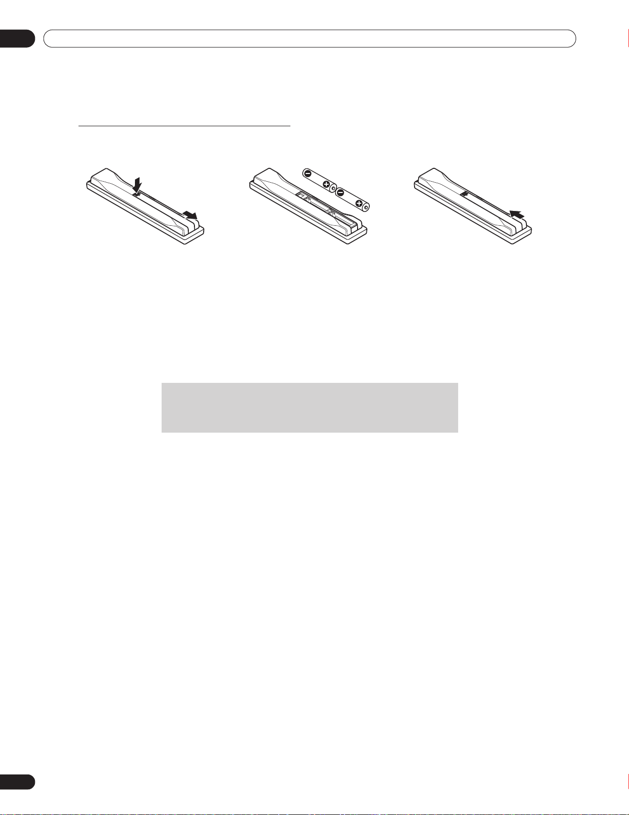
Insert the Batteries into the Remote Control
To open, push and slide the battery cover in the direction of the arrows.
Load the supplied two AA size batteries by the negative polarity (–) ends first.
The batteries supplied with this product may have a shorter life expectancy due to storage conditions. If the
remote control seems to be failing or is weak, replace the provided batteries with new alkaline batteries.
Never mix old and new batteries. Mixing old and new batteries can shorten the life of new batteries or cause
chemical leaks in old batteries. Also, mixing different types or brands of batteries can cause issues as batteries
brands have slightly different characteristics.
Note:
If the flat panel display’s remote control is not needed for an extended length of time, remove the batteries.
8
En
Page 9
Introduction to the Flat Panel Displays
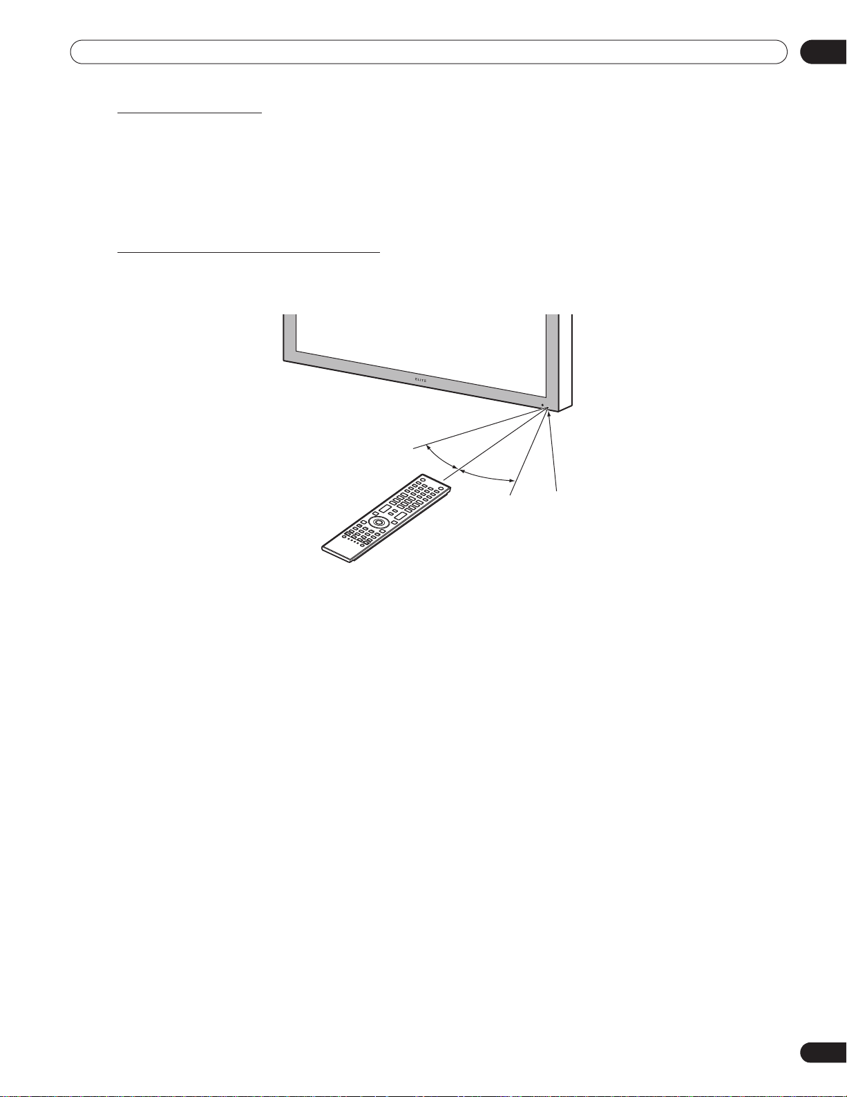
30º
Sensor
30º
7 m
(23 feet)
Remote Control Issues
There are a small number of issues that can affect your remote control but the most common is weak batteries.
Weak batteries in the remote control can cause communication to fail or only operate sporadically. In this
situation, try moving closer to the panel and attempt to control the panel with the remote. If the panel responds,
change the batteries. If moving closer has no effect on the panel, check the surroundings for objects that might
be blocking the signal. Also consider other equipment with remote controls that are in the area around the panel.
Objects and other IR signals can disrupt the remote. For more help with your remote control, refer to “7.1
Frequently Asked Questions (FAQs)”.
Operating Range for the Remote Control
To control the flat panel display, point the remote towards the sensor on the panel’s bottom right corner. For easy
operation, keep the distance between the remote control and the sensor less than 7 m (23 feet) and at an angle
of less than 30 degrees.
01
The remote control may not work properly if the sensor is in direct sunlight or very bright lighting. If your viewing
room is naturally bright, change the position of the panel or physically use the remote control closer to the panel’s
sensor.
Note:
If the remote control is left sitting in direct sunlight or under a very strong light, the case could warp or
deform.
9
En
Page 10
01
Introduction to the Flat Panel Displays
1.2.3 Buttons on the Remote Control
Except for a few options, commands available through the buttons on the flat panel display are duplicated on the
remote control. The remote control can be programmed to control other equipment such as a DVD Player,
Surround Sound system, etc. A later section entitled “6. Use Other Equipment With Your Flat Panel Display”
explains how to use the remote to control other equipment.
This section identifies and describes the buttons on the remote control.
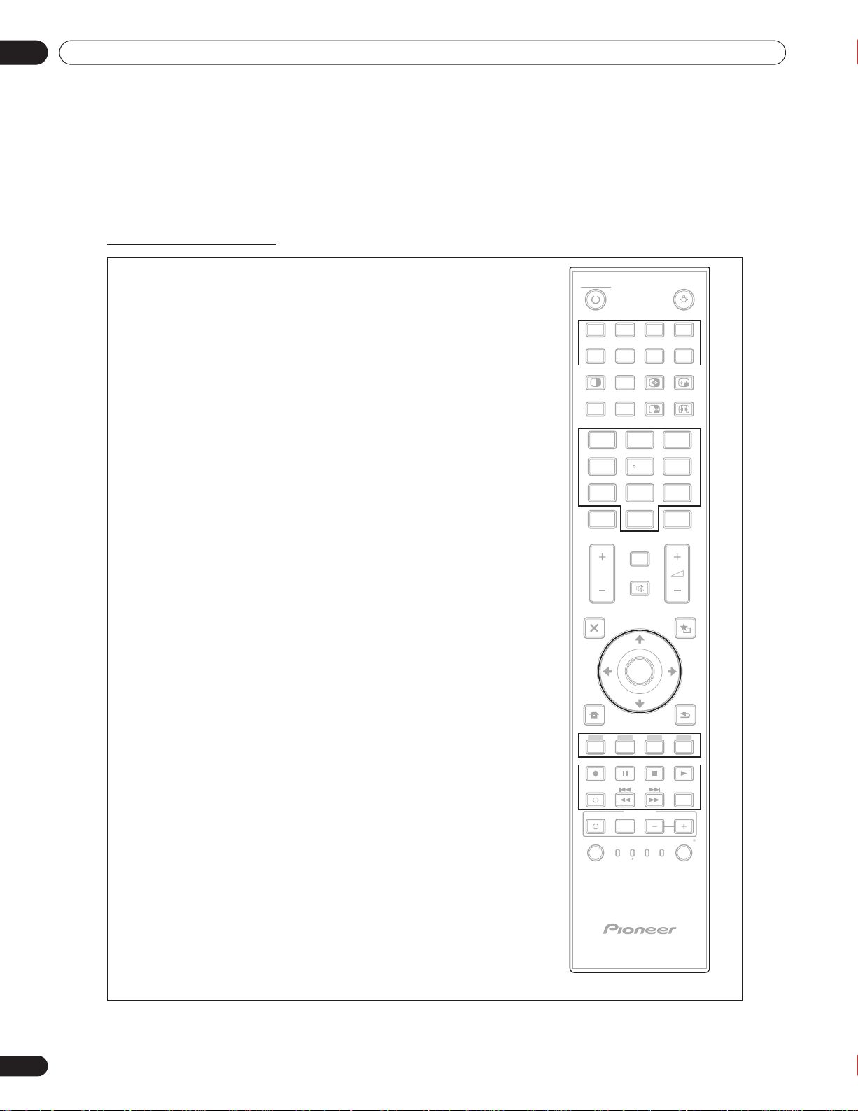
Remote: Left side buttons
(top to bottom, left to right)
MONITOR :
Turn On or place panel in Standby
Select a source (INPUT 1 thru INPUT 8)
Cycle view thru single-screen, 2-screen,
picture-in-picture
SUB INPUT:
Switch inputs for sub screens when viewing in multi-screen
AV SELECTION:
Select audio/video settings
AV Source: OPTIMUM, STANDARD, DYNAMIC, MOVIE,
PURE, SPORT, GAME, USER
PC Source: STANDARD, USER
AUTO SET UP:
Optimize the PC screen
Number buttons 0 thru 9:
Enter a number when applying IP Control Setting
KURO LINK:
Select the KURO LINK functions
Use the button for control of connected equipment
Exit the menu to return to the normal screen
Arrow buttons:
Navigate the menu screens
HOME MENU/MENU:
Display the HOME MENU
Color buttons (Red, Green, Blue, Yellow):
Control a BD player for KURO LINK functions only
INPUT:
SPLIT:
P/CH:
EXIT:
10
11
12
13
1
2
3
MONITOR
1
1
INPUT
SPLIT
34
AV
SELECTION
SET UP
5
INPUT
234
2
SUB
AUTO
SWAP
FREEZE
8765
PIP
SHIFT
SCREEN
SIZE
6
4
1
23
5
6
7
8
9
456
7
7809
KURO
LINK
8
DISPLAY
INFO
P/CH
MUTING
9
EXIT
10
TOP MENU
GUIDE
HOME
MENU
12
MENU
11
ENTER
CH
ENTER
USER MENU
TOOLS
RETURN
13
ON DEMAND
FAVORITE
DVD
DVR
BDP
LD
DVD/HDD
VOL
EDIT/LEARN
VCRSTBMONITOR
SOURCE
SELECT
15
14
RECEIVER
INPUT
CBL
SAT
10
En
Player/Recorder Control:
Use buttons for control of connected equipment
SELECT:
Select for MONITOR, STB, CBL/SAT, BDP/LD,
DVD/DVR, VCR
14
15
Page 11
Introduction to the Flat Panel Displays
01
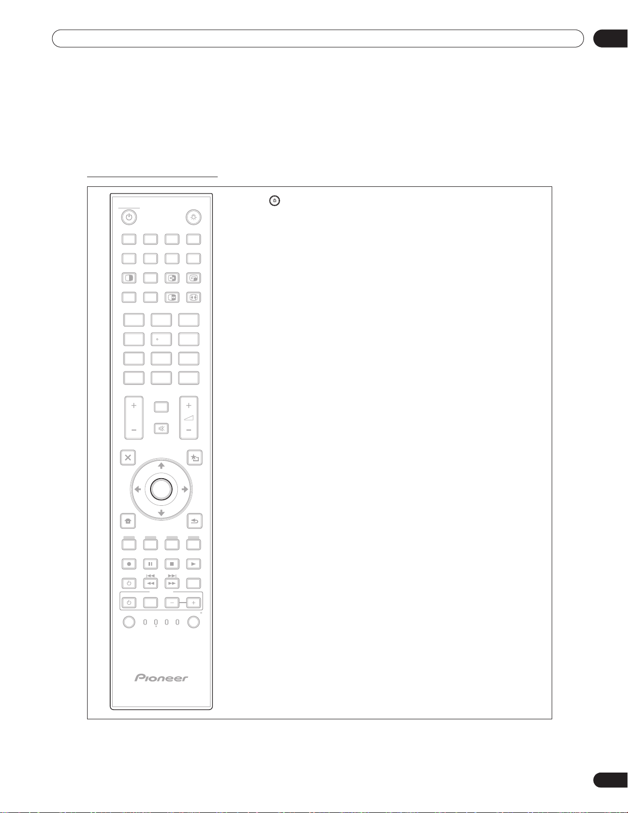
Remote: Right side buttons
MONITOR
16
INPUT
1
234
8765
PIP
SHIFT
SWAP
17 18
SCREEN
FREEZE
SIZE
19
20
SPLIT
AV
SELECTION
1
SUB
INPUT
AUTO
SET UP
23
456
7809
KURO
LINK
P/CH
DISPLAY
22
MUTING
INFO
CH
ENTER
21
23
24
EXIT
TOP MENU
GUIDE
HOME
MENU
MENU
ON DEMAND
SOURCE
SELECT
26
FAVORITE
RECEIVER
INPUT
CBL
SAT
ENTER
BDP
DVD
DVR
LD
USER MENU
25
27
DVD/HDD
VOL
EDIT/LEARN
VCRSTBMONITOR
TOOLS
RETURN
(top to bottom, left to right)
16 :Lights all buttons (except arrow buttons and the ENTER
button)
Lights turn off if no operations are performed within five
seconds. Use this button for remote control use in dimly lit
locations.
17 SWAP:
Switch between the two screens when
viewing as 2-screen or picture-in-picture
18 PIP SHIFT:
Move the location of the small screen when
viewing as picture-in-picture
19 FREEZE:
Freeze a frame from a moving image then
press again to cancel the freeze function
20 SCREEN SIZE:
Select the screen size
21 CH ENTER:
Use the button for control of connected equipment
22 DISPLAY/INFO:
Display the current monitor status
23
i +/–:
Invalid
24 MUTING:
Invalid
25 USER MENU/TOOLS:
Display the User Menu
26 ENTER:
Execute a command
27 RETURN:
Return to the previous menu screen
Note:
If you set the preset code to MONITOR, buttons 9, 13, 14 and 21
do not operate.
11
En
Page 12
02
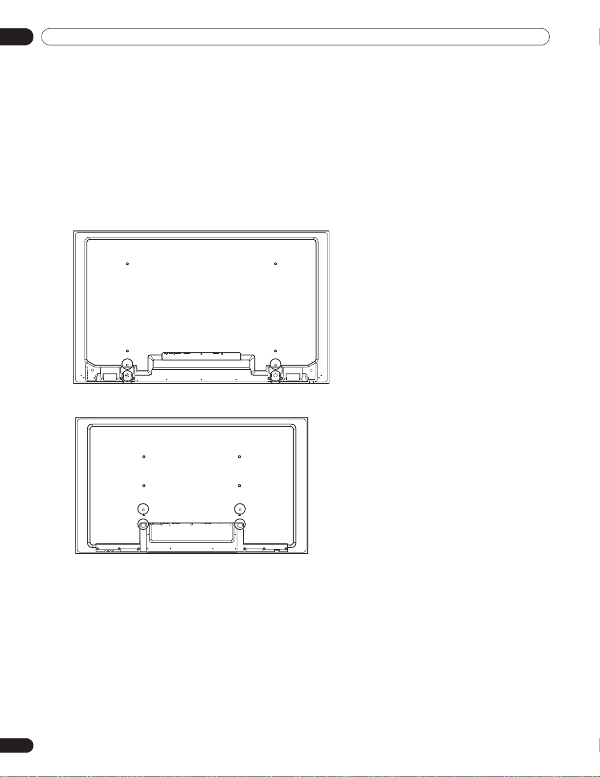
Rear view (PRO-141FD)
Rear view (PRO-101FD)
Install Your Flat Panel Display
2 Install Your Flat Panel Display
There are several installation options for your flat panel display. This chapter walks you through how to choose an
installation site, the best mounting methods, and how to install your panel.
2.1 Use the Optional Table Top Stand (Stand) or Equivalent Items
• Ask your dealer to perform the installation
• Use the supplied bolts
• For details, refer to the instruction manual that came with the optional stand (or equivalent items)
Use the supplied bolts when attaching the stand’s supports at the holes indicated by a circle.
12
En
Page 13
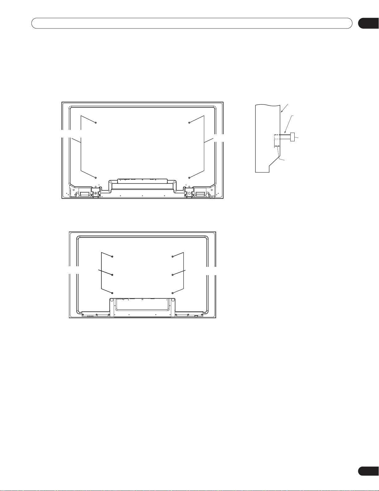
Install Your Flat Panel Display
Rear view (PRO-141FD)
Side view
Mounting surface
Mounting
bracket (or
equivalent item)
M8 screw
12 mm to 18 mm
(0.5 inches to
0.7 inches)
Rear view (PRO-101FD)
Mounting hole
Mounting hole
Mounting hole
Mounting hole
Mounting hole
2.2 Use the Optional Brackets or Equivalent Items
• Consult your dealer
• Use the following mounting holes for installation
02
Note:
Some installation options require a different type of bolt. Check with your installer or dealer to purchase the
appropriate bolt(s).
13
En
Page 14
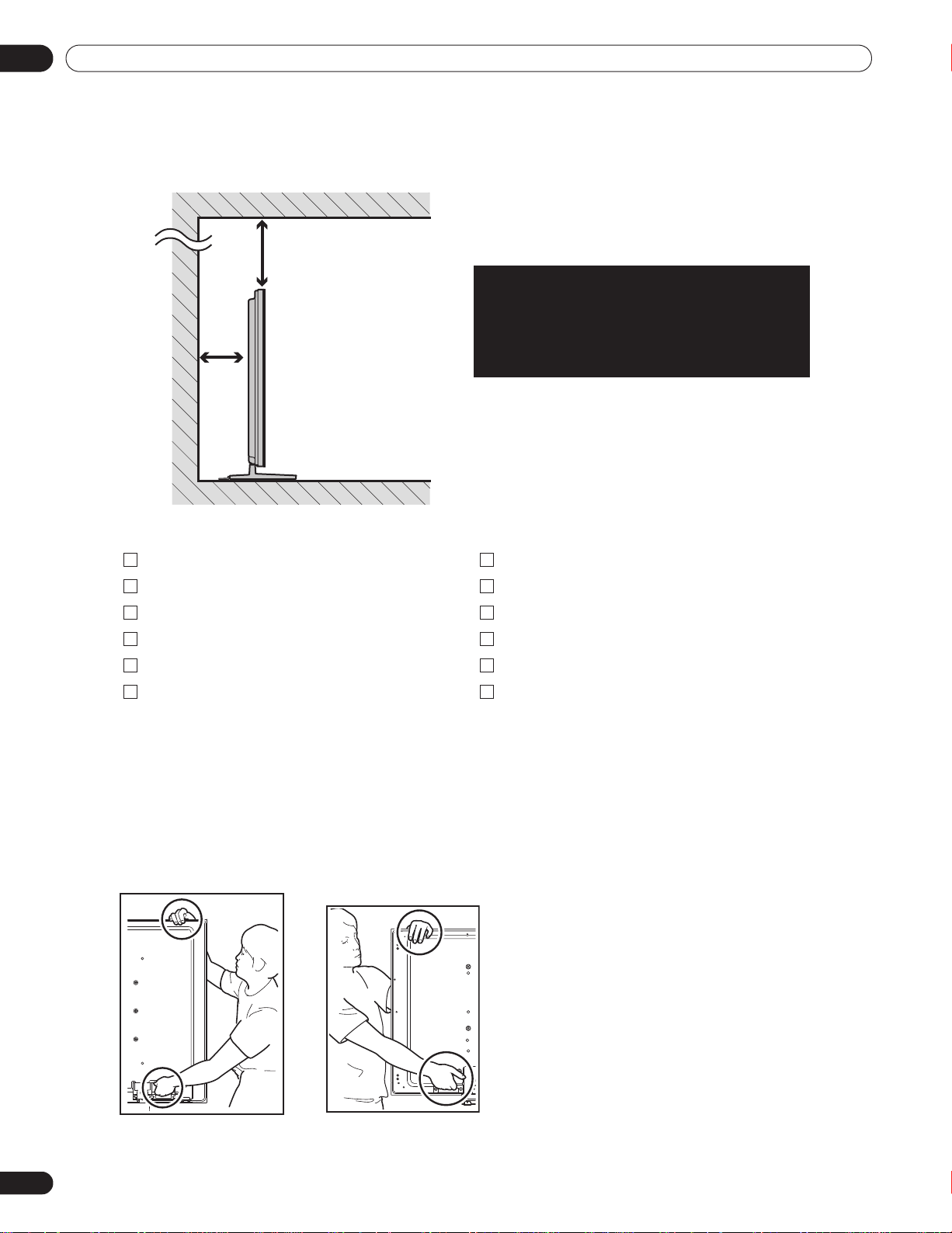
02
Over
10 cm
(3 15/16
inches)
Over 50 cm
(19 11/16 inches)
The distance behind and above the panel
changes depending on your choice of mount.
Consult with your dealer or professional
installer for proper ventilation.
(PRO-141FD)
(PRO-101FD)
Install Your Flat Panel Display
2.2.1 Check the Location for Suitability
When choosing the location for your panel, there are several factors to keep in mind. The installation site should
be out of direct sunlight and have sufficient ventilation around the flat panel display to allow cooling. The diagram
below is an example of a stand-mounted panel with proper ventilation.
Use the checklist below to judge possible installation sites.
Sufficient ventilation No danger of power overloads
Safe from excessive vibrations Separate from other IR equipment
Away from air conditioners Protected from hits or shocks
Free of moisture or dampness Distance from heat sources
No danger of splashing water Out of direct sunlight
Route cords and cables safely Away from strong lighting sources
For specific cautions and safety information, refer to “8.2 Physical Location & Temperature Considerations” and
“8.8 Safety Precautions.”
2.2.2 Lift and/or Move Your Panel (the How To’s)
This flat panel display is built for endurance but because of the technology, the panel must be handled with care.
Use the handles attached to the rear of the flat panel display to lift the unit. To avoid flexing or twisting the unit,
you need at least two people to lift and move the panel. Do not move the flat panel display by holding only a single
handle or by dragging the panel by its handles.
14
En
Note:
Do not use the handles to hang the flat panel display or as anchors to prevent the panel from slipping or
tipping after it is mounted.
Page 15
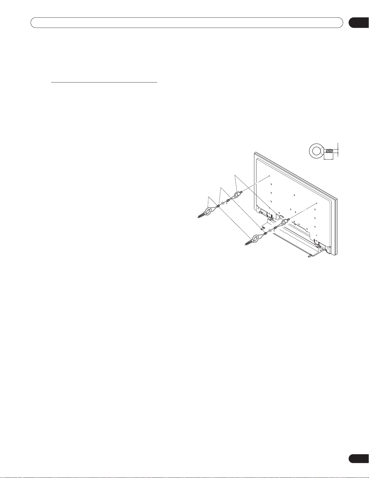
Install Your Flat Panel Display
Fitting
2.Cord
1.Hook
(PRO-141FD)
M8
12 mm to 18 mm
(0.5 inches to 0.7 inches)
2.2.3 Mount the Flat Panel Display
Because your flat panel display is slim but heavy, have at least two people mount and/or position the panel. The
following sections provide instructions for the different mounting and anchoring options.
Anchor the Panel When Using a Stand
When using a stand, stabilize the panel to keep it from tipping over. Please use the metal fittings and screws
supplied with the optional stand to anchor the panel to a wall or other solid support structure.
Another option is to purchase hooks, cords, and fittings through your installer or from your local hardware store.
The hardware size and strength depends on the composition and thickness of the anchoring surface.
Recommended hook: Nominal diameter 8 mm (3/8 inch), length 12 mm to 18 mm (0.5 inches to 0.7 inches)
To anchor the panel when using the optional stand, follow the steps below.
1 ) Attach the hooks to the mounting holes on the
back of the panel.
2 ) Sink the fittings into the wall or support structure.
3 ) Run cords between the hooks and the fittings.
4 ) Tighten the cords until the panel is anchored but
not pulled off balance.
02
To stabilize the flat panel display on a table or platform, use the metal fittings and screws supplied with the
optional stand as well as commercially available wood screws. The wood screws are to anchor the metal fittings
when mounting on a wooden surface. These screws should have a nominal diameter of 4 mm (5/32 inch) and are
at least 20 mm (13/16 inch) long.
Notes:
Avoid moving the table after the panel is attached.
Do not use bare wires for the cord. If any part of the wire is introduced into the ventilation port on the back
of the display panel, fire or electrical shock could result.
15
En
Page 16
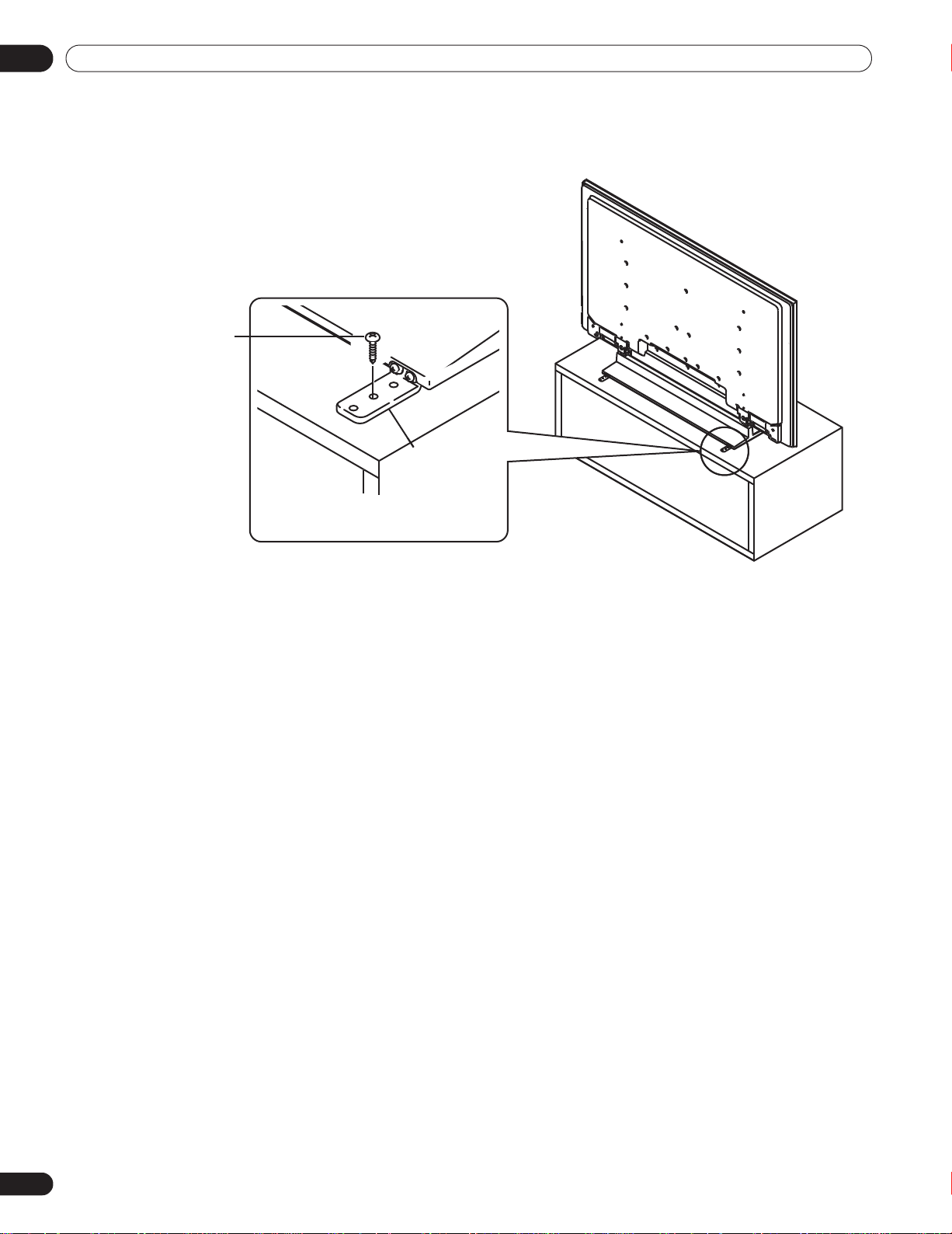
02
Falling prevention
metal fitting
(supplied with the
optional stand)
Wood screw
(commercially
available, 4 mm x
20 mm (5/32 inch x
13/16 inch) min.)
(PRO-141FD)
Install Your Flat Panel Display
Follow the steps below to secure your flat panel display.
1 ) Mark locations for metal fittings and screws on the back edge of the table using the panel stand to determine
placement.
2 ) Drill holes in the table or platform edge at the marked locations.
3 ) Lift panel into place with the assistance with at least one other person.
4 ) Use wood screws (not included) to secure the metal fittings to the table.
16
En
Page 17
Install Your Flat Panel Display
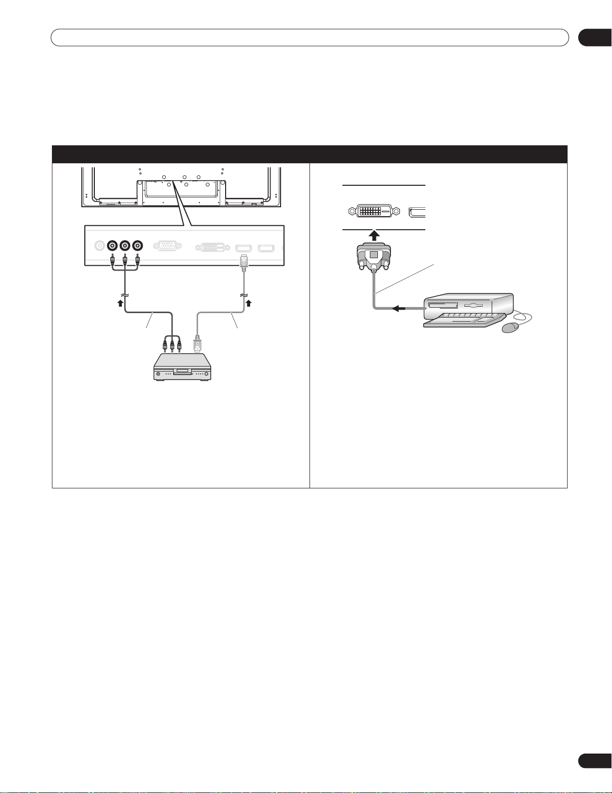
Use INPUT 2 terminals when connecting a DVD player
or other audio/visual equipment. If your DVD player has
an HDMI terminal, use this connection instead of
making video connections. For details, refer to the
operation manual that came with the DVD player.
DVD player
HDMI compliant
cable
(HDMI cable
having the HDMI
mark)
Component video cable
(commercially available)
Rear view
Use a DVI-D 24-pin (digital only) cable to connect a PC
equipped with a DVI output terminal (digital RGB
signal). After completing connections, follow the onscreen setup directions (page 52). INPUT 4 supports
Microsoft “Plug & Play” (VESA DDC 2B) components.
See “9.2 Video/PC Signals (HDMI/DVI/Component/min
D-Sub/Composite)” for information about signals and
display formats supported by INPUT 4.
Rear view
PC
DVI-D cable
(commercially available)
2.3 Connect to Other Devices (DVR, Receiver, BDR, etc.)
The type of equipment attached to your flat panel display determines which panel ports are used. The following
sections explain how to connect equipment such as a DVD player, video recorder, etc. to the panel. If your
equipment is not listed, please refer to the operating instructions that came with the device(s) for connection
assistance.
Connect a DVD player: Connect DVI equipment:
02
17
En
Page 18
02
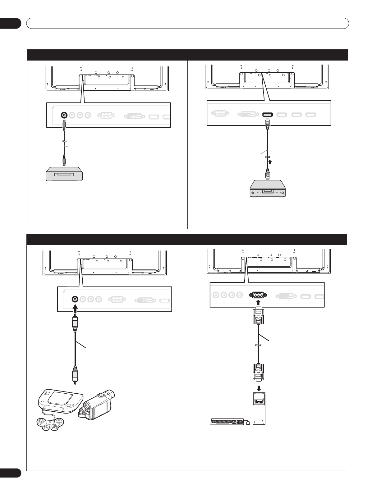
Use INPUT 1 terminal when connecting a VCR or other
recording equipment. For details, refer to the operation
manual that came with the device.
VCR
Video cable
(commercially available)
Rear view
HDMI equipment
HDMI compliant cable
(HDMI cable having
the HDMI mark)
Rear view
INPUT 5 through INPUT 8 are HDMI terminals. For
details, refer to “6.3 Use HDMI Inputs.”
Use INPUT 1 terminal when connecting a game
console, camcorder, or other audio/visual
equipment. For details, refer to the operation manual
that came with the game console or camcorder.
Rear view
Video cable
(commercially available)
Camcorder/Game console
Personal computer
Rear view
Use INPUT 3 terminal (Analog RGB) when connecting
a computer (PC). For details, refer to the operation
manual that came with the PC.
RGB cable
(commercially available)
Install Your Flat Panel Display
Connect a VCR: Connect HDMI equipment:
Connect a game console or camcorder: Connect a PC:
18
En
Page 19
Install Your Flat Panel Display
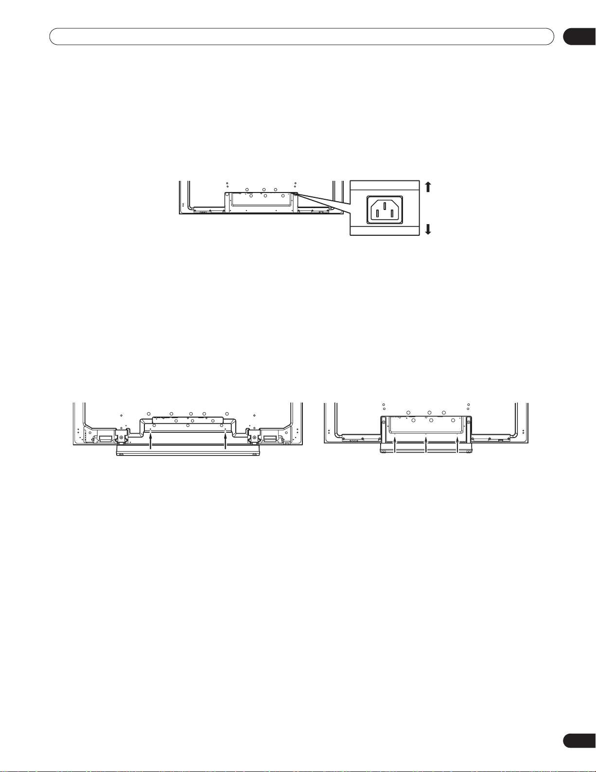
Front
Rear
PRO-141FD
PRO-101FD
2.4 Connect the Power Cord to the Panel
The final connection is the power cord. Always connect the panel’s power cord to a three-pronged outlet, verifying
that the cord is properly grounded. The cord includes a noise filter. Using any other cord may fail to conform to
mandatory FCC standards.
As long as the flat panel display is plugged in to an outlet, some power is drawn through the panel. When the flat
panel display is not going to be used for a long period, unplug the panel from the power outlet. Unplugging the
panel extends the life of the plasma as well as saves energy.
Plug the cord in to the panel but do NOT plug it in to a power outlet yet.
2.5 Route then Bundle the Power Cord and Cables
Once the flat panel display is mounted, place additional equipment in the final position(s). Lay out the power cord,
panel cables, and any other device cables in a logical pattern that works for the location. Please consider the
following points when routing cables:
• Access to a 3-prong (grounded) power outlet
• Space for the noise filter between the panel and outlet
• Placement of cables under carpets or across walking paths
A reusable cable clamp is designed to lock the bundled cables in place. Your flat panel display has a total of three
holes (60 inches: two holes) to attach cable clamps to the back of the panel. Use the cable clamps as necessary.
02
19
En
Page 20
02
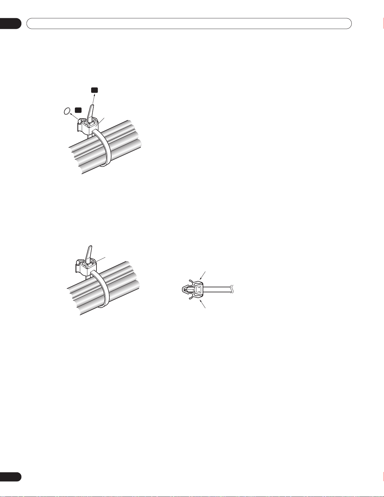
Cable clamp
Latch
Lever
Lever
Install Your Flat Panel Display
Follow the steps below to attach a cable clamp.
1 ) Thread the clamp band through the holder and bundle the cable(s) in the cable clamp.
2 ) Push and hold the levers then insert the hook into an appropriate hole on the rear of the flat panel display.
3 ) Pull up the clamp band to lock.
1
2
4 ) Confirm that the cable clamp is seated firmly in the panel.
Note:
Avoid pinching or creating pressure points when routing or bundling cables.
To remove the clamp band, pull and hold the latch to release.
To remove the cable clamp, push and hold the levers then pull it out from the hole.
Note:
The longer a clamp is in place, the better chance of deterioration. An older clamp is more easily damaged
while being removed and may not be reusable.
20
En
Page 21
Basic Operations
Power On indicator
Standby indicator
(PRO-101FD)
3 Basic Operations
This chapter explores day-to-day operations such as powering on your flat panel display, using the Home Menu,
User Menu, and adjusting the display for the viewing area/room. The final section in this chapter provides hints
and suggestions for those new to flat panel display features.
3.1 Turn the Flat Panel Display ON / OFF
Your flat panel display has three activity levels: Power On, Standby, and Power Off. Standby saves energy but
allows the remote control to turn on the panel. The following instructions use the remote control. To operate the
flat panel display through the side panel buttons, refer to “1.2.1 Control Buttons and More on the Flat Panel
Display” for button locations.
Turn ON the Flat Panel Display
To turn on the panel, follow the steps below.
1 ) Plug the flat panel display’s power cord in to a properly grounded outlet.
2 ) Press any of the following buttons to turn the flat panel display On.
• Power On button (a) on the panel’s back in lower-left section (see page 7)
• STANDBY/ON button on the side (PRO-141FD) or rear (PRO-101FD) of the panel (see page 7)
• Remote control’s MONITOR (a) button located in the upper left corner (see page 10)
Images appear on the panel screen.
03
3 ) Confirm that the Power On indicator lights blue.
Note:
While in Standby, pressing the remote control’s
MONITOR ( a )
button causes the flat panel display to turn
On.
Turn OFF the Flat Panel Display
Turning off the flat panel display can mean entering Standby so features are still functional or it can mean cutting
power to the panel. Unless the flat panel display is to sit idle for long periods, leave the panel in Standby.
Note:
While in Standby or when powered off, the display continues to draw some power as long as the panel is
plugged in to an outlet.
Follow the steps below to place the panel in Standby.
1 ) Press the remote control’s MONITOR ( a )
button.
2 ) Confirm that the Standby indicator lights red.
The table to the right provides samples of how the
indicators light. Monitor the indicators on the
front of the panel to check the power status.
Note:
Select from Auto, High, Mid and Low. Selecting
Auto toggles the brightness of the indicator
between High, Mid and Low to match the
Power
Indicator
Standby
Indicator
Flat Panel Display Status
Panel’s power cord is disconnected
or the power cord is connected but
the flat panel display’s Power On
button ( a ) is off
Power is on but waiting for activation
Panel is in Standby
brightness level of the viewing area. Refer to
“4.2.2 Adjust the Power Indicator Brightness.”
21
En
Page 22
03
Remote control
Home Menu screen
Basic Operations
3.2 Program Your Flat Panel Display
To take ad vantage of some built-in features, choose the input source, select a language and set the picture quality.
The sections below include how to use the Home Menu and simplified User Menu for each programming option.
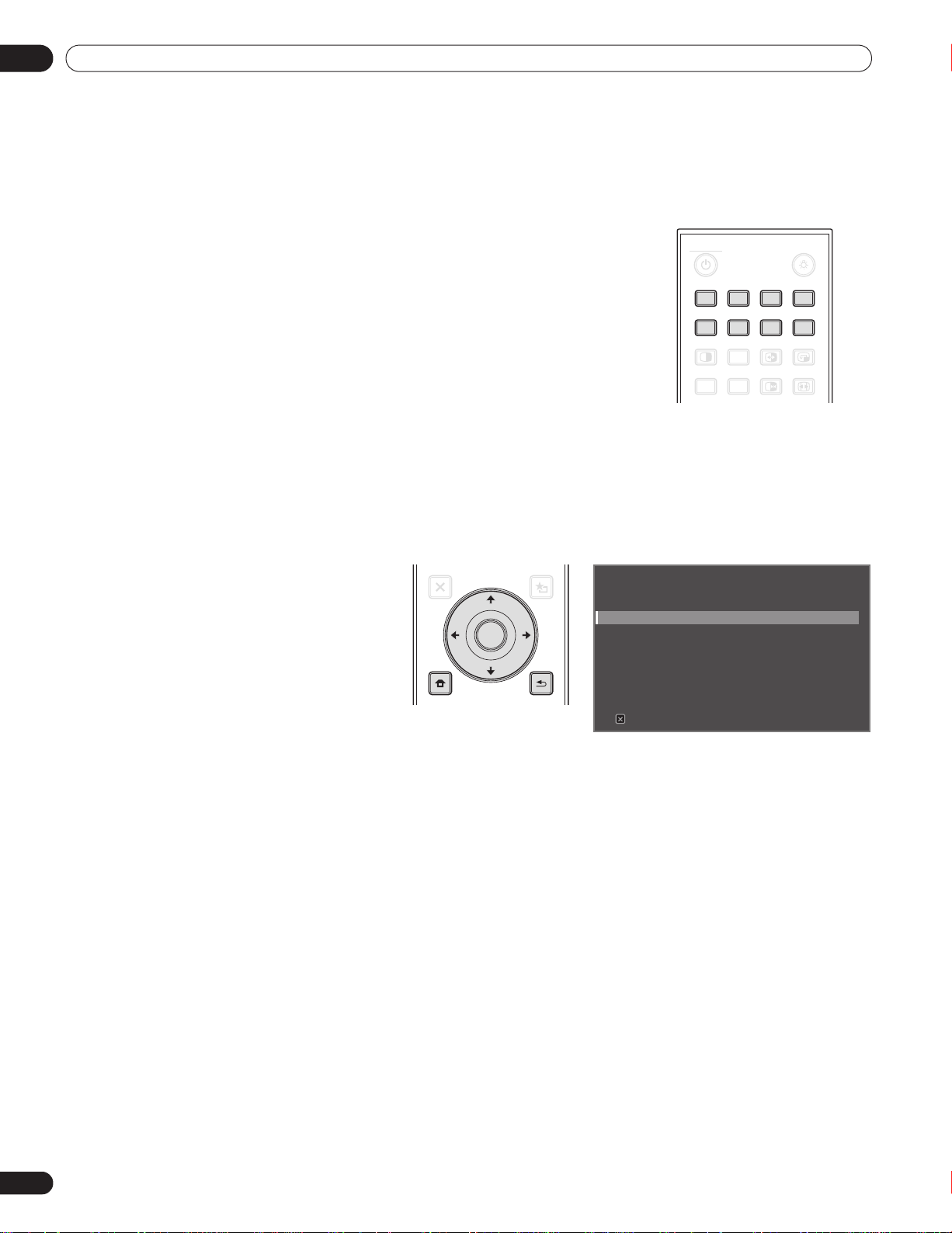
3.2.1 Choose an Input Source
To choose an input source, note that the external equipment is properly
connected to the input terminals on the back of the flat panel display. Follow
the directions below to choose an input source.
Press INPUT (buttons 1 through 8) on the remote control.
The corresponding terminal/port number is selected as an input source.
3.2.2 Explore the Home Menu
The Home Menu is the main menu for the flat panel display. Most commands and settings are programmed
through this menu. The following section describes a typical method for working with the panel’s menus. For
actual procedures, see the appropriate page(s) that describe individual functions.
MONITOR
INPUT
1 234
SUB
INPUT
SPLIT
AV
SELECTION
AUTO
SET UP
SWAP
FREEZE
8765
PIP
SHIFT
SCREEN
SIZE
1) Press HOME MENU on the remote
to access the main menu.
2) Use the Up/Down arrows (/) to
highlight a menu item.
3) Use the Left/Right arrows (/) to
scroll through options for that menu
item.
4) Highlight the selected menu option.
5) Press ENTER to lock in the change.
EXIT
TOP MENU
GUIDE
HOME
MENU
MENU
ENTER
USER MENU
TOOLS
RETURN
Picture
Screen
Power Control
Option
Input Setup
Control Setup
Exit
HOME MENU
FLAT PANEL DISPLAY
6) Press RETURN to move back to a previous menu/submenu page when changing more than a single option.
7) Press HOME MENU again to exit the menu screen.
22
En
Page 23
Basic Operations
User Menu screen
This chart provides a breakdown of the Home Menu.
Home Menu Pg Option Home Menu Pg Option
Picture 31 AV Selection Power Control 29 Energy Save
35 Contrast 45 Power Management
35 Brightness 45 No Signal Off
35 Color 45 No Operation Off
35 Tint Option 24 Language
35 Sharpness 28 Input Priority
37 Color Temp 28 Blue LED Dimmer
35 Red 29 Orbiter
35 Green 29 Video Pattern
35 Blue 28 Long Life Settings
38 Gamma 25 Room Light Sensor
38 Pro Adjust 44 PIP Detect
27 Reset Input Setup 52 Input Setup 1/2
Screen 53 Auto Setup 52 Input Setup 2/2
26 H. Position Control Setup 64 IP Control Setting
26 V. Position 58 KURO LINK Setting
53 Clock 69 Serial Setting
53 Phase
33 Auto Size
36 Side Mask
37 Reset
03
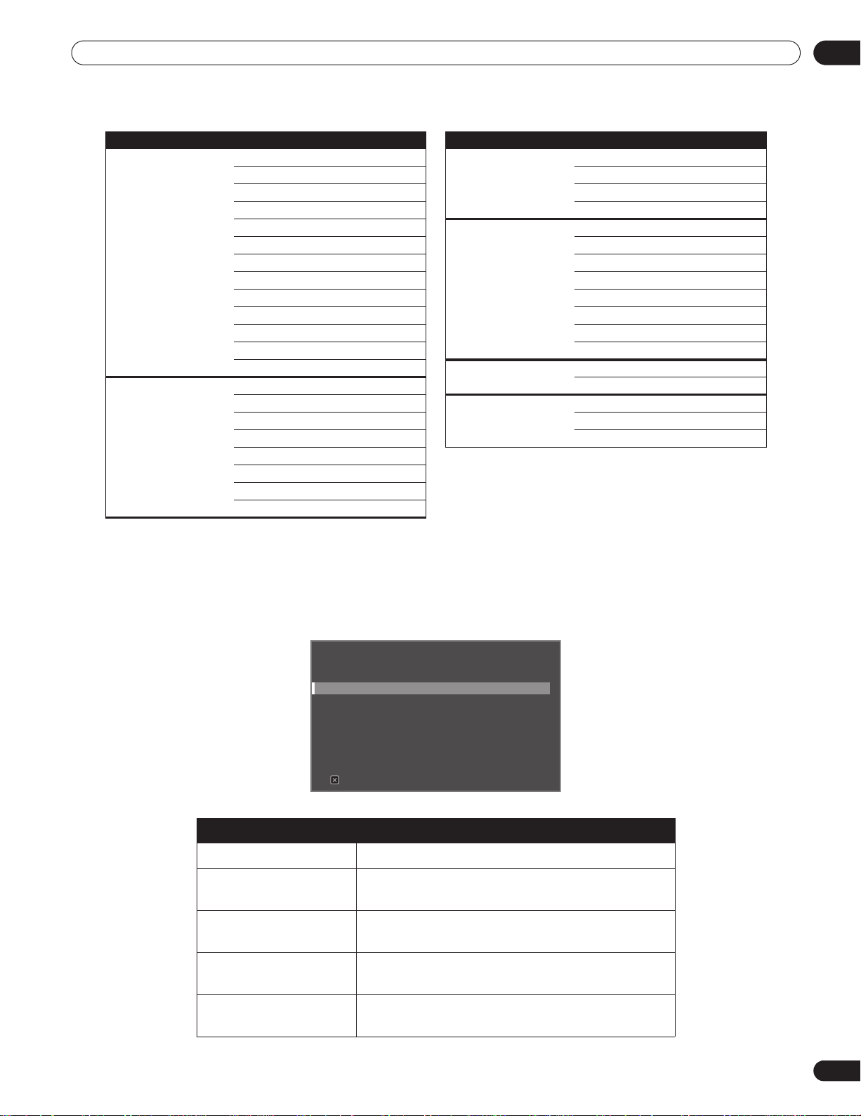
3.2.3 Use the Simplified User Menu
For simplified menu selections, the User Menu provides quick access to frequently used menus/submenus.
Press USER MENU on the remote control. For actual procedures, refer to “3.2.2 Explore the Home Menu”. The
following table shows the available menus.
USER MENU
FLAT PANEL DISPLAY
Input Change
AV Selection : Standard
Film Mode : Off
Sleep Timer
KURO LINK
Exit
User Menu Function
Input Change switches external input sources
AV Selection selects from eight viewing modes depending on the
picture (see page 31)
Film Mode reproduces theatre-quality images for film-based
sources (see page 38)
Sleep Timer places the panel into Standby when the set time
elapses (see page 30)
KURO LINK controls the connected equipment with the panel’s
remote through HDMI (see page 56)
23
En
Page 24

03
Basic Operations
3.2.4 Assign a Language
The default menu language is English. To assign a different language for menus and on-screen information,
follow the steps below.
1 ) Access
Language
2 ) Select a language from the submenu.
3 ) Press HOME MENU to exit the menu.
through the
Language : English
Input Priority : Off
Blue LED Dimmer : Low
Orbiter : Off
Video Pattern : Off
Long Life Settings : No
Room Light Sensor : Off
PIP Detect : Auto
Option
menu.
24
En
Page 25

Basic Picture Adjustment
4 Basic Picture Adjustment
This chapter explores basic picture adjustment options for your flat panel display.
4.1 Adjust the Picture Quality
Your flat panel display has many adjustment options for the picture to make it just right for you. This section
provides basic adjustments but for detailed video modifications, refer to “5 Additional Picture Adjustment
Options.”
4.1.1 Adjust the Picture for Your Room Lighting
The flat panel display senses the amount of light in your room and automatically adjusts the screen brightness
for the best picture. Bright rooms require stronger coloring so images appear crisp while dimly lit rooms allow
the picture to use more subtle coloring.
The panel ships with the Room Light Sensor turned Off. The sections below provide directions to turn the room
lighting sensor On/Off.
Room Lighting Sensor
To deactivate/reactivate the room lighting sensor, follow the steps below.
1 ) Access
Room Light Sensor
through the
Option
menu.
04
Language : English
Input Priority : Off
Blue LED Dimmer : Low
Orbiter : Off
Video Pattern : Off
Long Life Settings : No
Room Light Sensor : Off
PIP Detect : Auto
2 ) Select
3 ) Press HOME MENU to exit the menu.
On
(or
Off
) from the submenu.
4.1.2 General Picture (Video) Adjustment
The directions below apply to all AV Selection options except OPTIMUM and DYNAMIC. If the viewing option is
OPTIMUM, your flat panel display automatically adjusts the picture to the best possible level. If the preferred
viewing option is DYNAMIC, please refer to “5.1 Choose an AV Option (Video, Game, etc.).”
25
En
Page 26
04
Basic Picture Adjustment
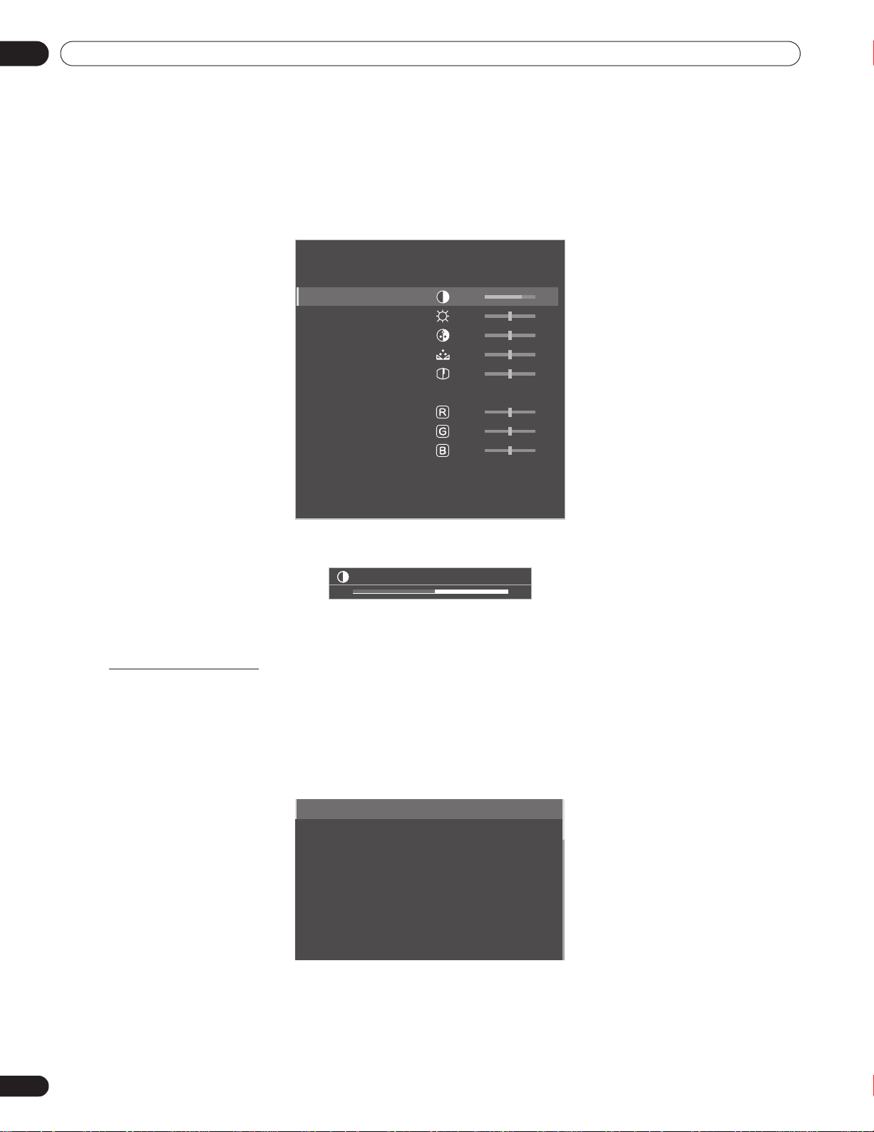
For standard picture adjustments, follow the steps below.
1 ) Press HOME MENU.
2 ) Select
Picture
Use the arrow buttons to highlight an option then press
from the main menu.
ENTER.
3 ) Select an item to be adjusted.
Contrast is used in the example below.
Picture
AV Selection : STANDARD
Contrast : 40
Brightness : 0
Color : 0
Tint : 0
Sharpness : 0
Color Temp : Mid
Red : 0
Green : 0
Blue : 0
Gamma : 3
Pro Adjust
Reset
4 ) Use the arrow buttons (/) to adjust to the desired level.
Contrast
32
5 ) Press HOME MENU again to exit the menu.
Picture Image Position
Each input source stores the picture adjustment settings for that view. Although repositioning is available in most
screen views, when the screen is set to Dot by Dot, the Position menu is unavailable. Also, depending on the
displayed video, the image position may not change after an adjustment.
To adjust the picture’s horizontal and vertical position, follow the steps below.
1 ) Access
H.Position
or
V. P o s i ti o n
through the
Auto Setup
H.Position
V.Position
Clock
Phase
Auto Size
Side Mask
Reset : No
Screen
menu.
2 ) Adjust the vertical and/or horizontal positioning using the arrow buttons.
26
En
3 ) Press HOME MENU to exit the menu.
Page 27

Basic Picture Adjustment
Restore Default Picture
After making multiple adjustments, it may be difficult to reverse improper settings. To restore the factory default
Picture settings, follow the directions below.
Reset
1 ) Access
2 ) Press ENTER to continue with the picture reset.
from the Picture menu.
04
3 ) Use the arrow buttons to highlight
4 ) Press ENTER.
Yes
.
All Picture settings return to the original default values.
4.1.3 Compare Images When Adjusting the Picture
When adjusting the picture, look for an overall improvement by adjusting each parameter or option one at a time.
Many small adjustments lead to the best picture for your viewing area. As each option changes, refer back to the
previously set image for comparison. This section includes adjustment notes and steps to adjust the picture.
Each parameter/option must be adjusted separately. For example, if two options under AV Selection, STANDARD
and MOVIE need adjustment, change/compare one option then save the preferred setting before moving on to
the other option. Below are other guidelines for picture adjustment.
Before
• Adjustments are available while on the After screen. Trying to make adjustments while on the
a warning message to appear.
After
• Switch to another parameter/option only from the
Before
another option, the
• Exiting an option from the
• Exiting an option from the
• Moving/changing the AV Selection parameter/option stores the option setting in memory (the button
continues to work).
Follow the steps below to adjust options for the preferred picture quality.
1 ) Press HOME MENU.
data is lost.
Before
screen stores that previous entry in memory and deactivates the button.
After
screen stores the new entry in memory and deactivates the button.
screen. If viewing the
Before
screen when selecting
causes
2 ) Select
Picture
Use the arrow buttons to highlight an option then press
3 ) Select an option.
4 ) Press USER MENU while the adjustment menu is on screen.
from the main menu.
ENTER
.
The word “Before” appears on screen with the unadjusted picture showing in Step 2.
5 ) Press USER MENU again.
The adjusted picture appears and the word “Before” disappears.
Pressing
6 ) Repeat Steps 3 through 5 to adjust other picture options.
7 ) Press HOME MENU again to exit the menu.
Notes:
If no selections are made within 60 seconds, the menu closes automatically and the current settings are
USER MENU
toggles the picture between Before and After.
saved to memory.
“Before” is canceled if:
• The STANDBY/ON button,
INPUT, SWAP
or
AV SELECTION
is pressed
• input signal changes
To exit the menu without saving the changes, switch to the Before screen then press HOME MENU.
27
En
Page 28

04
Basic Picture Adjustment
4.2 Smart Starts for New Owners
Many of the flat panel display features make it easier to use but also environmentally friendlier. This section
explains how to extend the life of your panel through being energy efficient. We suggest applying all of the
following functions below for the simplest usage, best quality, and longest life span.
4.2.1 Extend Your Panel Life
This function provides short-cuts to your panel’s longer service life. Your flat panel display includes a Long Life
Settings option. Activating this option causes the panel to automatically select several different features that can
prolong the life of your panel and help alleviate after-image ghosts or burn-in. To set this option, follow the steps
below.
1 ) Access
Long Life Settings
A confirmation screen appears.
through the
Option
menu.
2 ) Select
Yes
from the submenu.
The following settings are automatically entered:
•Auto Size: Wide Zoom
•Side Mask - Detection: Mode 1
•Orbiter (AV source): Mode 1
•Orbiter (PC source): Mode 1
•Energy Save: Save 1
•AV Selection: OPTIMUM (only when it was set to DYNAMIC previously)
3 ) Press HOME MENU to exit the menu.
4.2.2 Adjust the Power Indicator Brightness
Adjust the brightness of the Power On indicator depending on the brightness level of the viewing area. Setting to
Auto toggles the brightness of the indicator between High, Mid and Low to match the brightness level of the
viewing area. To set the indicator, follow the directions below.
1 ) Access
2 ) Select
3 ) Press HOME MENU to exit the menu.
Blue LED Dimmer
Auto, High, Mid
through the
or
Low
from the submenu.
Option
menu.
4.2.3 Set Input Priority
With a priority input assigned, the flat panel display automatically switches to that input when signals are present.
To set the priority input, follow the directions below.
1 ) Access
Input Priority
through the
Option
menu
.
28
En
2 ) Select
3 ) Select the desired input.
4 ) Press HOME MENU to exit the menu.
Auto
from the submenu.
Detecting another signal at a different input causes the selected input to automatically change to the new
input.
After input changes, the previous input is not restored even when the signal disappears at the input.
Page 29

Basic Picture Adjustment
4.2.4 Turn On the Image Orbiter
A built-in feature to protect against burn-in is the Orbiter function. Orbiter slightly changes the position of the
picture while the image is on screen.
To activate Orbiter, follow the steps below.
1 ) Access
Orbiter
through the
Option
menu.
04
2 ) Select
Mode 1, Mode 2 or Off
.
• AV source Mode 1: for any screen mode except Dot by Dot
• AV source Mode 2: for all available screen modes
• PC source Mode 1: to enable Orbiter
• PC source Mode 2: to smooth the text/character appearance
3 ) Press HOME MENU to exit the menu.
Note:
The farthest edges of an image may be hidden at times as the picture position shifts. Also, when the Orbiter
function is set to Mode 1 or Mode 2, the image may appear to drop slightly on the screen.
4.2.5 Trigger the Screen-Saving Video Pattern Periodically
The Video Pattern function causes the screen to appear white, which helps to alleviate after-image ghosts or burnin. While the Video Pattern screen is on, only the remote’s MONITOR (a) button and the panel’s STANDBY/ON
button are available. The panel automatically switches to Standby one hour after running the Video Pattern
screen. To cancel the Video Pattern screen, press the remote’s MONITOR (a) or press the panel’s STANDBY/ON
button.
To activate the Video Pattern screen, follow the steps below.
1 ) Access
Video Pattern
through the
Option
menu.
A confirmation screen appears.
2 ) Select
Start
from the submenu.
The Video Pattern screen appears.
3 ) Leave the panel alone for a minimum of one hour.
Note:
The Video Pattern timer has priority over Sleep Timer, No Signal Off, and No Operation Off (Power
Management) settings.
4.2.6 Activate Energy Save to Reduce Power Usage
The Energy Save option decreases picture brightness and lowers power consumption. The recommended setting,
Save 1, extends the life of your panel while keeping power usage at a minimum.
Follow the steps below to activate an Energy Save option.
1 ) Access
2 ) Select an option from the Energy Save submenu.
3 ) Press HOME MENU to exit the menu.
Note:
To deactivate the screen, select Picture Off.
Energy Save
Standard No effect
Save 1 consumes less power than Standard
Save 2 consumes less power than Save 1
Picture Off activates Picture Off when closing the Home Menu
through the
Option Description
Power Control
with this option selected
menu
.
29
En
Page 30

04
Basic Picture Adjustment
4.2.7 Turn On the Sleep Timer
To save energy and to maximize the life of your flat panel display, try using the Sleep Timer for occasions when
the panel may be left on by accident. The Sleep Timer places the panel in Standby when the selected time elapses.
The Sleep Timer provides time periods of 30, 60, 90, or 120 minutes. When the Timer is down to five minutes, a
reminder appears on screen each minute until the time has elapsed.
To set the Sleep Timer, follow the steps below.
1 ) Press USER MENU.
2 ) Select
3 ) Select the desired time period.
Sleep Timer
from the User Menu.
Select between 30 minutes and two hours (120 minutes).
4 ) Press USER MENU again to exit the menu.
Note:
When the sleep timer has been set, “Remain ---min” appears at the top of the menu.
The Video Pattern timer has priority over the sleep timer. When the Video Pattern timer is on, the sleep timer
is deactivated. Video Pattern is explained in an earlier section in this manual.
30
En
Page 31

Additional Picture Adjustment Options
5 Additional Picture Adjustment Options
To take advantage of all that your flat panel display offers, browse this chapter for features and functions that
enhance your viewing experience. Most sections deal with adjusting the picture and arranging screen/menu
items while the remaining sections provide power management options. Apply as many or as few of these
changes as desired.
5.1 Choose an AV Option (Video, Game, etc.)
Similar to the purpose for the room light sensor, the AV Option or Selection depends upon the brightness of the
environment and the movie on screen. Images can be from either an AV Source or from a PC. Both sources are
discussed below.
Choose from among the seven AV Selections for the best image from an external AV Source. Use either the
remote control or the Home Menu to select the AV source. For a PC, skip down to “5.1.3 Choose a PC Source.”
If the AV source is a Game Control, select GAME and refer to “5.1.4 Set the Panel to Recognize a Game Console”
for more information.
5.1.1 AV Source through the Remote Control
Follow the directions below to set the AV Selection for an external AV Source.
05
1 ) Press AV SELECTION on the remote control.
The current AV selection appears.
2 ) Press AV SELECTION again before the displayed mode disappears.
Each press cycles the options in the order shown below.
AV Selection
OPTIMUM automatically adjusts the image quality for the
brightness level of the viewing area
STANDARD for a highly defined image in a normally bright
room
DYNAMIC for a very sharp image with maximum contrast but
manual image quality adjustment unavailable
MOVIE for movies
PURE reflects input signals as faithfully as possible for
checking image materials, for example
SPORT for sports programs
GAME lowers image brightness for easier viewing
USER allows customizing settings as desired (set the
mode for each input source)
Description
3 ) Allow the AV Selection screen to disappear.
When the menu screen disappears, the panel locks in the last viewed option.
31
En
Page 32

05
When OPTIMUM is selected,
images are reproduced based on
the information collected at the
Room Light Sensor.
Additional Picture Adjustment Options
5.1.2 Choose an AV Source through the Home Menu
Another method for choosing an AV Selection uses the Home Menu.
The AV Selection, OPTIMUM, automatically adjusts to the highest image quality possible for the selected source
and viewing environment.
DYNAMIC locks out manual adjustments for specific options. The DYNAMIC setting blocks Contrast, Brightness,
Color, Tint, Sharpness, and Reset. Unavailable options are dimmed on the menu.
To choose an AV source through the Home Menu, follow the steps below.
1 ) Access
AV Selection
2 ) Select an option from the submenu.
AV Selection
OPTIMUM
STANDARD
DYNAMIC
MOVIE
PURE
SPORT
GAME
USER
through the
Picture
menu.
3 ) Press HOME MENU to exit the menu.
5.1.3 Choose a PC Source
From a PC, choose between two AV Selections for the best image. The options are as follows:
• STANDARD: for a highly defined image in a normally bright room
• USER: allows customizing the settings for each input source
5.1.4 Set the Panel to Recognize a Game Console
When adding a game console to your flat panel display, use the Game function to establish a preference for image
quality or for operability.
To have the panel store your Game preference, follow the steps below.
1 ) Access
Pro Adjust
through the
Picture
menu.
2 ) Select Other from the Pro Adjust menu.
3 ) Select
4 ) Select
Game Control Pref.
On
(operability preferred) or
from the submenu.
Off
(image quality preferred).
5 ) Press HOME MENU to exit the menu.
To activate the Game Control Pref. option, set the AV Selection to GAME and use an external input (unless the
sourse is coming from a PC). When a PC source menu is on screen, the
Also, the
Game Control Pref
in Multi-Screen”) and image freezing
. option for operability (on) is ignored during multi-screen viewing (refer to “5.4 View
(refer to “5.5 Freeze the Picture”).
Game Control Pref.
option is ignored.
32
En
Page 33

Additional Picture Adjustment Options
5.2 Adjust Specific Picture Elements
Plasma technology delivers one of the best images available today. However, the viewing area/environment and
personal preferences affect how the picture appears. This section provides methods to adjust the picture for your
best viewing experience.
5.2.1 Choose a Screen Size (Automatically or Manually)
Automatic Screen Sizing
The flat panel display can automatically select an appropriate screen size for a video signal coming from an HDMI
device. To allow automatic screen sizing, follow the steps below.
1 ) Access
Auto Size
through the
Screen
menu.
05
2 ) Select
3 ) Press HOME MENU to exit the menu.
Note:
Natural
or
Wide Zoom
Option Description
Off deactivates the Auto Size function
Natural adjusts the image to the screen size
Wide Zoom enlarges and displays only the 4:3 aspect ratio
from the submenu.
portion in full and wide screen
When a video signal contains no aspect ratio information, the Automatic Screen Size function is
unavailable.
33
En
Page 34

05
Additional Picture Adjustment Options
Manual Screen Sizing
Manually select an appropriate screen size if an image fails to appear in the correct format. Browse the menu for
the specific video signal’s correct screen size.
The selectable screen sizes differ depending on the type of input signal. While watching video content, press
SCREEN SIZE on the remote control to cycle the picture through Auto, FULL, Dot by Dot, ZOOM, CINEMA, 4:3,
WIDE, WIDE 1, WIDE 2, FULL 14:9 and CINEMA 14:9. Freely change the screen size during video from other input
sources. Auto is available when receiving HD pictures.
The following chart provides information about how the screen appears for each option.
AV Option Description
Auto adds side masks or displays the image in full
screen when detecting HD pictures containing side
masks (See Detect Masks on page 36)
FULL (FULL 14:9) squeezes 16:9 (14:9) images
Dot by Dot
ZOOM bars may appear on the top and bottom on some
CINEMA
CINEMA 14:9
4:3 side bars appear on each side
WIDE pictures progressively stretch toward each side
WIDE 1 pictures progressively stretch toward each side
WIDE 2 pictures evenly stretch toward each side (available
PC Option Description
4:3 fills without altering the input signal aspect ratio
FULL shows 16:9 screen display
With WIDE 1 or WIDE 2 selected, a High Definition (HD) picture image or menu may run off the edge of the
screen. If an image or menu appears cut or cropped, change the option to FULL.
Avoid showing signals that fill only part of the screen. Images that fail to fill the screen may cause temporary or
permanent image retention depending on the frequency and duration. For example, an HD picture with side
masks (4:3 content) causes uneven wear of the plasma cells. If side masks appear around a broadcast, after that
movie or program is over, switch to a full screen motion video. This action helps the panel balance wear for the
plasma cells and guard against after-image issues. For more information about Masks, refer to “5.3.1 Adjust for
Screen Masking (black bars on sides).”
matches input signal to the same number of screen
pixels (available for 1080i or 1080p signals only)
pictures that are 16:9 letterbox
bars may appear on the top and bottom on some
pictures that are 14:9 letterbox (available for SD
signals only)
(available for SD signals only)
(available for HD signals only)
for HD signals only)
34
En
Note:
Not all video signals carry alternative screen sizes.
Page 35

Additional Picture Adjustment Options
(AV source)
5.2.2 Correct the Picture for an AV or PC Source
Although picture adjustments are to your personal preferences, often the source causes unanticipated image
changes. Your flat panel display offers several adjustment options.
AV Source
Option Left Arrow Right Arrow
Contrast less contrast more contrast
Brightness dimmer brighter
Color weaker intensity stronger intensity
Tint purplish skin tones greenish skin tones
Sharpness softer definition crisper definition
Color Temp adjusts white tone to your preference
Gamma adjusts the balance of image’s bright and dark portions
PC Source
Option Left Arrow Right Arrow
05
Contrast less contrast more contrast
Brightness dimmer brighter
Red weaker color stronger color
Green weaker color stronger color
Blue weaker color stronger color
To correct the picture for an AV or a PC source, follow the steps below.
1 ) Press HOME MENU.
2 ) Select
Picture
Use the arrow buttons to highlight an option then press
from the main menu.
ENTER
.
3 ) Select an option to adjust.
Picture
AV Selection : STANDARD
Contrast : +38
Brightness : -7
Color : -6
Tint : 5
Sharpness : 4
Color T emp : Mid
Gamma : 5
Pro Adjust
Reset
Exit
35
En
Page 36

05
Additional Picture Adjustment Options
4 ) Select the desired level for that option using the left/right arrows (/).
Contrast
5 ) Repeat the process for any additional adjustments.
6 ) Press HOME MENU again to exit the menu after all adjustments are complete.
Note:
Reset returns all settings to the factory defaults.
32
5.3 Assign Advanced Picture Functions
Your flat panel display provides various advanced functions for optimizing the picture quality that go beyond basic
adjustments explained earlier in this manual. This section explores the value offered through Pioneer’s Pro Adjust
support, top quality blacks, better balanced whites, and overall color improvements.
5.3.1 Adjust for Screen Masking (black bars on sides)
Screen Masks fill areas on both sides of a picture. Some content fails to fill the screen so bars appear on each
side of the picture. This section explains how to adjust screen masking.
Detect Masks
Some HD video signals have 4:3 content with side masks. Side masks are black bars that appear on the picture’s
left and right sides. If the flat panel display’s Screen Size is set to Natural during the Auto Size process, gray bars
replace the black bars. When the panel is set to Wide Zoom, the bars are hidden. These responses reduce afterimage concerns.
To allow the panel to detect side masks, follow the steps below.
1 ) Access
Side Mask
through the
Screen
menu.
2 ) Select
3 ) Select
Detection
Mode 1
or
from the submenu.
Mode 2
to activate Side Mask Detection.
Mode 1 detects only black side masks and Mode 2 detects both black and illustrated side masks. Select Off
to deactivate this function.
4 ) Press HOME MENU to exit the menu.
Video signals can affect the Side Mask Detection function differently. For High Definition pictures when Side
Mask Detection is on, the panel automatically detects images containing side masks and shows the picture in
full screen.
Cycle the screen size to select Auto for video signals that do not carry aspect ratio information.
Video content also can affect the Side Mask Detection function. If a detection error occurs when trying to watch
HD content, manually change the screen size to the proper setting for the content.
HD Wide Mode
The HD Wide Mode allows selecting the display mode (WIDE 1 or WIDE 2) when detecting side masks that appear
in a 4:3 image. This option is available when the Auto Size menu is set to Wide Zoom and Side Mask Detection to
Mode 1 or Mode 2. To allow the HD Wide Mode, follow the steps below.
1 ) Access
2 ) Select
3 ) Select
Side Mask
HD Wide Mode
Mode 1
through the
or
Mode 2
Screen
from the submenu.
to activate HD Wide Mode.
menu.
• Mode 1: screen mode sets to WIDE 1 when detecting side masks.
• Mode 2: screen mode sets to WIDE 2 when detecting side masks.
4 ) Press HOME MENU to exit the menu.
36
En
Page 37

Additional Picture Adjustment Options
Lighten Side Masks
If content appears with bars (side masks) on each side of a picture when the screen size is 4:3 and Side Mask
Detection is active, the bars automatically change from black to gray. However, the gray is fairly dark. To change
the bars to a lighter shade of gray, follow the steps below.
1 ) Access
Side Mask
through the
Screen
menu.
05
2 ) Select
3 ) Select the desired parameter.
4 ) Press HOME MENU to exit the menu.
Restore Default Screen
To restore the factory default screen settings, follow the directions below.
1 ) Access
2 ) Press ENTER to continue with the screen reset.
3 ) Use the arrow buttons to highlight
4 ) Press ENTER.
Brightness Sync.
Parameter Description
Fixed sets the same brightness for gray side masks
Auto adjusts the side mask brightness according to the
Reset
through the
from the submenu.
brightness of screen images
Screen
menu
.
Yes.
All screen settings return to the original default values.
5.3.2 Select a Color Temperature Level
Use this option to adjust the color temperature for a better white balance. To adjust the white balance, follow the
directions below.
1 ) Access
Color Temp
through the
Picture
menu
.
2 ) Select the desired parameter from the submenu.
Parameter Description
High white with bluish tone
Mid-High intermediate tone between High and Mid
Mid natural tone
Mid-Low intermediate tone between Mid and Low
Low white with reddish tone
Manual adjusts to your preference
To manually adjust the white balance, continue with the following Steps.
3 ) Select
4 ) Press ENTER to confirm.
5 ) Use the right arrow button to adjust the balance.
Manual
in Step 2.
The manual adjustment screen appears.
6 ) Select an option to adjust.
37
En
Page 38

05
Additional Picture Adjustment Options
7 ) Select the desired level.
Option Left Arrow Right Arrow
R High fine adjustment for
G High weaker green stronger green
B High weaker blue stronger blue
R Low fine adjustment for dark
G Low weaker green stronger green
B Low weaker blue stronger blue
8 ) Press RETURN to repeat Steps 6 and 7 as often as needed for additional adjustments.
9 ) Press HOME MENU to exit the menu.
bright portions
portions
weaker red stronger red
weaker red stronger red
5.3.3 Adjust the Image Gradation Characteristics (Gamma)
Use this option to adjust the image characteristics (gamma characteristics). For adjustments, follow the
directions below.
1 ) Access
2 ) Select 1 through 5 from the submenu.
3 ) Press HOME MENU to exit the menu.
Gamma
through the
Picture
menu.
5.3.4 Select a PureCinema Level for High Quality Image
Pioneer’s PureCinema automatically detects and analyses a film-based source (originally encoded at 24 frames
per second) then recreates each frame for HD picture quality. The function supports both film and text material.
To set the PureCinema level for your HD material, follow the steps below.
1 ) Access
2 ) Select
3 ) Select
4 ) Select the desired parameter.
Pro Adjust
PureCinema
Film Mode
Mode Parameter Description
Film Mode Off deactivates PureCinema
Tex t
Optimization
through the
from the Pro Adjust menu.
or
Text Optimi zation
Standard (not available for input
signals 480p, 720p@60 Hz, or
1080p@60 Hz)
Smooth (not available for input
signals 1080p@60 Hz)
Advance (not available for input
signals 1080p@60 Hz)
Off deactivates text optimization
On improves subtitle display
Picture
menu
.
, depending on the material.
automatically detects recorded
DVD or high-definition images
(e.g., movies) having 24 frames
per second for smooth and vivid
playback
produces smoother and more
vivid moving images
converts theatre-quality DVD
images to 72 Hz (e.g., movies)
quality
38
En
Page 39

Additional Picture Adjustment Options
5 ) Press HOME MENU to exit the menu.
Notes:
Activating the Game Control Pref. setting under the Option menu disables the PureCinema setting.
This setting applies only to input video signals.
5.3.5 Select an Intelligent Mode Option
Use this function to optimize image color tones and brightness.
To select the Intelligent Mode, follow the steps below.
1 ) Access
Pro Adjust
through the
Picture
menu
.
05
2 ) Select
3 ) Select
4 ) Select the desired parameter.
5 ) Press HOME MENU to exit the menu.
Notes:
Intelligent Mode
Mode 1
or
Parameter Description
Off No effect
Mode 1 compensates for more effective picture settings
Mode 2 compensates for appropriate picture settings
from the Pro Adjust menu.
Mode 2
(or
Off
).
Although this function gradually optimizes the image quality, tint and brightness changes may be visible.
This is normal and is not a malfunction.
This setting applies only to input video signals.
39
En
Page 40

05
Additional Picture Adjustment Options
5.3.6 Select the Picture Detail Options
The Picture Detail function provides four adjustment options: DRE Picture, Black Level, ACL, and Enhancer Mode
for enhanced image contrast and sharpness.
To select the Picture Detail options, follow the steps below.
1 ) Access
Pro Adjust
through the
Picture
menu
.
2 ) Select
3 ) Select
4 ) Select the desired parameter.
Picture Detail
from the submenu.
DRE Picture, Black Level, ACL
Option Parameter Description
DRE Picture (emphasizes
image contrast between light
and dark)
Black Level (emphasizes dark
portion of images for enhanced
contrast)
ACL (compensates images for
optimum contrast)
Enhancer Mode (processes the
image’s high frequency
(detailed) area)
or
Enhancer Mode.
Off No effect
High enhances DRE picture
Mid standard DRE picture
Low moderate DRE picture
Off No effect
On activates Black Level
Off No effect
On activates ACL
1 (Hard) selects Hard (SHARPNESS)
image
2 (Natural) selects Natural (SHARPNESS)
image
3 (Soft) selects Soft (SHARPNESS)
image
40
En
5 ) Press HOME MENU to exit the menu.
Note:
This setting applies only to input video signals.
5.3.7 Use CTI and Color Space
Use the Color Transient Improvement (CTI) and Color Space options to further picture enhancement.
To set the CTI and Color Space options, follow the steps below.
1 ) Access
2 ) Select
3 ) Select
4 ) Select the desired parameter.
5 ) Press HOME MENU to exit the menu.
Pro Adjust
Color Detail
CTI
or
CTI Off No effect
Color Space 1 optimizes for vivid, vibrant color
through the
from the Pro Adjust menu.
Color Space
from the submenu.
Option Parameter Description
Picture
menu
.
On activates CTI
2 standard color reproduction
Page 41

Additional Picture Adjustment Options
Note:
This setting applies only to input video signals.
5.3.8 Use the Color Management
Use the Color Management option to fine adjust image coloring.
To set the Color Management option, follow the steps below.
1 ) Access
2 ) Select
3 ) Select
4 ) Select the desired parameter.
5 ) Select the desired level.
Pro Adjust
Color Detail
Color Management
R closer to magenta closer to yellow
Y closer to red closer to green
G closer to yellow closer to cyan
C closer to green closer to blue
B closer to cyan closer to magenta
M closer to blue closer to red
through the
from the Pro Adjust menu.
Item Left Arrow Right Arrow
Picture
from the submenu.
menu
.
05
6 ) Press RETURN or use the /button to repeat Steps 4 and 5 as needed.
7 ) Press HOME MENU to exit the menu.
Note:
This setting applies only to input video signals.
5.3.9 Reduce Noise from the Image
Use the video noise reduction features for clear and crisp images. Refer to the table below for available video
noise reduction.
To select the Noise Reduction options, follow the steps below.
1 ) Access
2 ) Select
3 ) Select
4 ) Select the desired parameter.
Pro Adjust
Noise Reduction
3DNR, Field NR, Block NR
3DNR (3-dimensional Noise
Reduction)
Field NR (removes glimmer for
more natural image)
Block NR (reduces noise in HD
images)
Mosquito NR (reduces mosquito
noise in DVD and HD images)
through the
from the Pro Adjust menu.
Option Parameter Description
Picture
menu
or
Mosquito NR.
.
Off No effect
High enhances DNR
Mid standard DNR
Low moderate DNR
Off No effect
High enhances Field NR
Mid standard Field NR
Low moderate Field NR
Off No effect
On activates Block NR
Off No effect
On activates Mosquito NR
41
En
Page 42

05
Additional Picture Adjustment Options
5 ) Press HOME MENU to exit the menu.
Note:
This setting applies only to input video signals.
5.3.10 Adjust Color Signals
Your flat panel display features various color signal adjustment options: 3DYC, I-P Mode, Drive Mode, Game
Control Pref., and Blue Only Mode. Use these options to adjust color signals for both video and still images.
To select color signal adjustment options, follow the steps below.
1 ) Access
Pro Adjust
through the
Picture
menu
.
2 ) Select
3 ) Select
4 ) Select the desired parameter.
Other
from the Pro Adjust menu.
3DYC, I-P Mode, Drive Mode, Game Control Pref.
Option Parameter Description
3DYC (optimizes characteristics
for separating brightness
signals from color signals)
I-P Mode (provides optimum
conversion from interlace
signals to progressive signals)
Drive Mode (switches image
display frequency)
Game Control Pref. (establishes
a gaming preference for image
quality or operability)
or
Blue Only Mode.
Off No effect
High enhances 3DYC
Mid standard 3DYC
Low moderate 3DYC
1 (Motion) optimizes video images
2 (Standard) standard setting
3 (Still) optimizes still images
1 standard setting
2 enhances readability for
horizontally scrolling text
3 optimizes movie content
Off image quality preferred
On operability preferred
42
En
Blue Only Mode (displays
images in blue only)
Drive Mode
To activate the Game Control Pref. option, set the AV Selection to GAME. This option is unavailable for a PC source.
Also, the Game Control Pref. option for operability (On) is ignored during multi-screen viewing (page 43) or image
freezes (page 44).
5 ) Press HOME MENU to exit the menu.
Notes:
is unavailable when setting
Reset returns all settings to factory defaults.
Off No effect
On activates Blue Only Mode
Game Control Pref.
to
Off
.
This setting applies only to input video signals.
Page 43

Additional Picture Adjustment Options
2-Screen
Picture-in-Picture (P-in-P)
5.4 View in Multi-Screen
The flat panel display can show multiple screens at the same time; two-screen or picture-in-picture. The pictures
may be reversed (in 2-screen and P-in-P) or moved to various locations on the screen (P-in-P).
5.4.1 Split / Swap / Shift the Screen
To split the screen so that two input sources appear, press the SPLIT button on the remote control. Each press of
the button cycles the screen through two-screen, picture-in-picture, and single-screen views.
To switch the image sides/locations, press the SWAP button.
05
To move the Picture-In-Picture (P-in-P) small image counter-clockwise, press the SHIFT button.
43
En
Page 44

05
Press SPLIT to cycle through the
different multi-screen views.
Press SWAP
to switch the position
of the two screens.
Press PIP SHIFT
to move the position
of the small screen counterclockwise during P-in-P.
Press SUB INPUT
to switch the input
sources between the two screens.
Warning: Displaying pictures in multi-screen mode
for an extended period may cause an after-image.
Additional Picture Adjustment Options
.
MONITOR
INPUT
1 234
SWAP
FREEZE
8765
PIP
SHIFT
SCREEN
SIZE
external
input
SUB
INPUT
SPLIT
AV
AUTO
SELECTION
SET UP
The multi-screen function is unavailable when viewing source from a single input or from two
sources.
To return to a single picture, press HOME MENU.
5.4.2 Turn the Small Screen On/Off
Set your flat panel display to automatically hide the small screen window if no input signals appear on the small
screen during P-in-P (only a frame remains on screen). To activate this option, follow the directions below.
1 ) Access
2 ) Select
PIP Detect
Auto
from the PIP Detect menu.
through the
Option
menu.
The small screen disappears in approximately three seconds if no signal is received. The display restores
the image when an input signal is present.
3 ) Press EXIT to exit the menu.
Note:
PIP Detect is unavailable in two-screen mode.
5.5 Freeze the Picture
During fast-action sequences or detailed pictures, try capturing the image with the FREEZE option. FREEZE
allows you to better understand the action or picture details when desired. To freeze a picture from a TV broadcast
or movie, follow the steps below.
1 ) Press FREEZE to create a still image picture
(copy) of the currently showing image.
The copy appears to the right of the still-moving
video sequence thus splitting the screen.
2 ) Press FREEZE again to release the image.
The frozen image disappears, returning the
picture to a single screen with the video
sequence still in progress.
• With the screen split, an image cannot be frozen.
44
En
A warning message appears if you attempt to use this function when there is already a frozen image on screen.
If an image is left frozen on the screen, the panel automatically releases the image after five minutes.
Note:
Using FREEZE for an extended period may cause an after-image.
MONITOR
INPUT
1 234
SUB
INPUT
SPLIT
AV
SELECTION
AUTO
SET UP
SWAP
FREEZE
8765
PIP
SHIFT
SCREEN
SIZE
Page 45

Additional Picture Adjustment Options
5.6 Manage the Power
Your flat panel display is energy efficient but includes functions to save additional power. In an earlier section
entitled “4.2 Smart Starts for New Owners”, you were told how to activate the Energy Save feature. This section
provides more advanced functions to save power and to extend the panel life.
AV Source - No Signal
To save energy and extend the life of your display, the panel can enter Standby automatically if the AV source
signal fails for 15 consecutive minutes. At five minutes before and at every minute after that, a warning message
appears on the screen. When the final minute elapses, the panel switches to Standby.
To have the panel switch to Standby when an AV source signal fails, follow the steps below.
1 ) Access No Signal Off
through the Power Control menu
.
05
2 ) Select
3 ) Press HOME MENU to exit the menu.
AV Source - Non-Operational
To save energy, the panel can enter Standby automatically if there are no commands from the AV source for three
consecutive hours. At five minutes before and at every minute after that, a warning message appears on the
screen. When the final minute elapses, the panel switches to Standby.
To have the panel enter Standby automatically when there are no commands from the AV source, follow the steps
below.
1 ) Access
2 ) Select
3 ) Press HOME MENU to exit the menu.
PC Source -Power Management
When receiving signals from a PC, the panel can enter Standby automatically if the signal fails. Follow the steps
below to activate this function.
1 ) Access
2 ) Select an option from the submenu.
Enable
Enable
to activate the AV Signal off power function.
No Operation
from No Operation Off menu.
Power Management
Off no power management (default)
Mode 1 panel enters Standby when no signal is received
Off through the
through the
Option Description
Power Control
Power Control
from the PC for
effect on the panel
eight minutes
menu.
menu
.
, using the PC has no
Mode 2 panel enters Standby when no signal is received
Notes:
Pressing the remote’s
from the PC for
effect on the panel
MONITOR (a)
eight seconds
button or the panel’s
, using the PC has no
STANDBY/ON
button reactivates the flat panel
display.
When the panel enters Standby with Mode 1 selected (no signals received), receiving signals again does
not cause the flat panel display to turn On.
When the panel enters the Power Management status with Mode 2 selected (no signals received),
receiving signals again causes the flat panel display to turn On.
3 ) Press HOME MENU to exit the menu.
These power management options are unavailable when a PC is connected to the panel through the HDMI port/
terminal.
For video and PC signals applicable to the flat panel display, see “9.2 Video/PC Signals (HDMI/DVI/Component/
min D-Sub/Composite).”
45
En
Page 46

06
EDIT/LEARN
VCRSTBMONITOR
BDP
LD
DVD
DVR
CBL
SAT
SELECT
INPUT
1 2 34
8765
2 cm to 5 cm (0.8 inches to 2.0 inches)
Remote control
(Supplied accessory)
Remote control of
AV product
Use Other Equipment With Your Flat Panel Display
6 Use Other Equipment With Your Flat Panel
Display
Although earlier sections have mentioned other equipment for playing back video, this section provides control
and operation information for specific types of equipment.
6.1 Program the Remote Control to Operate Other Equipment
To operate other equipment or devices through your flat panel display, program the panel’s remote control with
the equipment’s manufacturing code. A manufacturing code is a series of numbers that identify the type of device
and the brand. These codes are available in the section entitled “Manufacturer Codes to Program into the Remote
Control” in Appendix 9.1 of this manual.
6.1.1 Use the Learning Function
The Learning function allows the panel’s remote control to memorize codes
to control other devices.
To set the Learning function to On, follow the directions below.
1 ) Press SELECT to choose the other device.
2 ) Simultaneously press the EDIT/LEARN and 2 buttons to begin.
The selected mode indicator flashes when the remote control is ready
to be programmed.
3 ) Use the number buttons to learn a manufacturing code.
The mode indicator lights up.
The Learn session is canceled in 30 seconds and the indicator begins
blinking again. When the indicator flashes, the selected device’s
remote is memorized.
When you press a button that cannot be learned, the indicator
continues to blink.
To exit the Learn mode before it finishes, press
EDIT/LEARN.
4 ) Press EDIT/LEARN again to exit the Lean mode after the code is confirmed.
:
Notes: The Learn session cancels if:
• no operation is performed for more than one
minute after having pressed
EDIT/LEARN
and 2
(the mode indicator is flashing)
•you press
SELECT
Code transmission finishes in approximately two
seconds. Do not interrupt the process until the
transmission is complete.
46
En
When using any of the receiver buttons
(a, INPUT
, or
VOL+/–)
, the learned manufacturer
code remains the same.
Page 47

Use Other Equipment With Your Flat Panel Display
EDIT/LEARN
VCRSTBMONITOR
BDP
LD
DVD
DVR
CBL
SAT
SELECT
INPUT
1 234
8765
MENU
EXIT
USER MENU
RETURN
ON DEMAND
SOURCE
DVD/HDD
VOL
RECEIVER
EDIT/LEARN
VCRSTBMONITOR
BDP
LD
DVD
DVR
CBL
SAT
SELECT
FAVORITE
INPUT
TOOLS
TOP MENU
GUIDE
HOME
MENU
ENTER
123 4
8765
To delete a learned code, overwrite it with a new code on the same button or follow the directions below.
1 ) Simultaneously press the EDIT/LEARN and 2 buttons to begin.
The selected mode indicator flashes when the remote control is ready to be programmed.
2 ) Press and hold MONITOR a for at least two seconds.
The remote control starts deleting all learned codes for selected modes. When completed, the mode
indicator blinks Off and the remote control returns to normal operation.
6.1.2 Assign a Manufacturing Code to the Remote Control
To assign a preset Manufacturing code to the panel’s remote control,
follow the directions below (Manufacturing codes are listed in section
“9.1 Manufacturer Codes to Program into the Remote Control”).
1 ) Press SELECT to choose the device to program.
2 ) Simultaneously press the EDIT and 1 buttons to begin.
The selected mode indicator flashes when the remote control is
ready to be programmed.
3 ) Use the number buttons to enter a manufacturer code.
When the indicator turns off, the code has been stored in the
remote control.
06
Factory default manufacture codes:
STB (Set-top Box): Pioneer (0329)
BDP/LD/DVD/DVR: Pioneer (2052)
VCR (VTR): Pioneer (0058)
6.1.3 Issue a Library Search for a Manufacturer Code
If the code for a particular device is unknown, cycle through the available
codes for a similar unit then sample some functions for that code.
To find a code that can control the unit, follow the steps below using
different codes to find the best match.
1 ) Press SELECT to choose the device to program.
2 ) Simultaneously press the EDIT and 3 buttons to begin.
The selected mode indicator flashes when the remote control is
ready to search the code library.
3 ) Sample a code using a SOURCE POWER, PLAY, 1 or CH+
command.
4 ) Use the up/down arrow (/) buttons to advance to the next code
if the sampled code fails to control the device.
Another option is to return to the previous code and repeat Step 3.
5 ) Press ENTER to lock in the code that properly operates the device.
All the available buttons for the selected mode are added when the
mode indicator flashes on for one second. The remote control then
returns to normal operation.
47
En
Page 48

06
MEN
U
ON DEMAND
SOURC
E
DVD/H
DD
VOL
RECEIVE
R
EDIT/LEAR
N
VCR
STBMONITO
R
BDP
L
D
DVD
D
V
R
CBL
SAT
SELEC
T
FAVORIT
E
INPUT
MONITOR
INPUT
1234
Use Other Equipment With Your Flat Panel Display
6.1.4 Clear Added Manufacturer Codes from the Remote Control
To return all learned and preset codes to the defaults (PIONEER), follow the steps below.
1 ) Simultaneously press EDIT and MONITOR () buttons to begin.
Selection can be in any mode.
2 ) Press the Yellow button to clear added codes.
Confirm that the selected mode indicator flashes.
The remote control enters the Manufacturing Reset mode. The
reset is complete when the mode indicator flashes once. The
remote control then returns to normal operation.
Note: The panel’s remote control may not control or have complete
control of some equipment listed in the tables.
To exit before the reset is complete, press the EDIT button again. The reset is cancelled if no action is taken within
60 seconds. Switching the Mode during this procedure also cancels the reset.
6.1.5 Control a Pioneer Receiver
The flat panel display’s remote control has a bank of buttons specifically for controlling a Pioneer receiver. The
active buttons, left to right, are as follows:
• RECEIVER STANDBY/ON
(turns the Pioneer Receiver On/Off)
• RECEIVER INPUT
(cycles through/selects an input)
• RECEIVER VOL –
(adjusts the volume lower)
SOURCE
SELECT
RECEIVER
INPUT
CBL
SAT
DVD
DVR
BDP
VOL
VCRSTBMONITOR
LD
• RECEIVER VOL +
(adjusts the volume higher)
DVD/HDD
EDIT/LEARN
48
En
Page 49

Use Other Equipment With Your Flat Panel Display
6.1.6 Control a Cable (CBL) or Satellite (SAT) System
When Mode is set to CBL/SAT, a cable converter uses the buttons 1, 2, 5, and 6. However, the panel only
recognizes a single system (cable or satellite) at a time.
1
• Number buttons
(press to enter a channel number)
2
• P/CH +/–
(selects a higher or lower channel)
3
• ENTER
(ENTER activates the selected function)
4
• SOURCE
(turns the equipment power on and off)
5
• CH ENTER*
(enters the selected channel with the direct
channel selection buttons)
6
• RETURN
(restores the immediately previous screen)
* Some cable converter manufacturers do not preset
CH ENTER.
1
2
MONITOR
INPUT
1
234
SUB
INPUT
SPLIT
AV
SELECTION
1
SWAP
AUTO
FREEZE
SET UP
23
456
7809
KURO
LINK
DISPLAY
INFO
P/CH
MUTING
SHIFT
SCREEN
CH
ENTER
SIZE
8765
PIP
06
5
EXIT
TOP MENU
GUIDE
3
HOME
MENU
MENU
ON DEMAND
FAVORITE
SOURCE
4
SELECT
RECEIVER
INPUT
CBL
SAT
ENTER
DVD
BDP
DVR
LD
USER MENU
DVD/HDD
VOL
EDIT/LEARN
VCRSTBMONITOR
TOOLS
RETURN
6
49
En
Page 50

06
Use Other Equipment With Your Flat Panel Display
6.1.7 Control a Video Cassette Recorder (VCR)
When Mode is set to VCR, verify that the proper Input is selected (INPUT 1 to INPUT 8) then use the numbers 1
to 8 to control the device.
1
• P/CH +/–
(selects a higher or lower channel)
2
• RECord
(begins recording)
3
• PAUSE/STILL
(pauses playback and displays still images)
4
• SOURCE
(turns the VCR’s power on and off)
5
• REWind
(rewinds the VCR tape and allows searches)
6
• STOP
(halts VCR tape transport)
7
• PLAY
(selects playback)
8
• FF
(advances the VCR tape and allows searches)
1
2
3
4
5
7809
KURO
LINK
DISPLAY
P/CH
MUTING
EXIT
TOP MENU
GUIDE
ENTER
HOME
MENU
MENU
ON DEMAND
FAVORITE
SOURCE
RECEIVER
INPUT
SELECT
CBL
SAT
INFO
BDP
DVD
DVR
LD
CH
ENTER
USER MENU
DVD/HDD
VOL
EDIT/LEARN
VCRSTBMONITOR
TOOLS
RETURN
6
7
8
50
En
Page 51

Use Other Equipment With Your Flat Panel Display
6.1.8 Control a DVD Player/DVR Recorder/BD Player
When Mode is set to DVD/DVR, the remote control can operate a DVD player, DVD recorder or BD player
connected to the flat panel display. Verify that the proper Input is selected for the device then use the numbers 1
to 14 to control it.
Note:
Equipment from other manufacturers (DVD players, DVD recorders, BD players, and HD-DVD players) can
also be operated using the panel’s remote control if the remote is programmed for the device(s).
1
• P/CH +/– (DVD Recorder only)
(selects a higher or lower channel)
2
• DVD TOP MENU
(displays the top menu on the DVD)
3
• ENTER
(ENTER activates the selected function)
(arrows to select from MENU screens)
4
• DVD MENU
(displays the DVD menu)
5
• Red/Green/Blue/Yellow (BD only)
(controls a BD-J application)
6
• RECord (DVD Recorder only)
(begins recording)
7
• PAUSE/STILL
(pauses playback and displays still image)
8
• SOURCE
(turns the equipment power on or off)
9
• REVERSE SCAN/CHAPTER SEARCH
(press once quickly to go to beginning of current
chapter; press again to go back to the beginning of
the previous chapter; continue pressing to go
backward)
10
• TOOLS
(assigns the code for a Pioneer BD player)
11
• RETURN
(restores the immediately previous screen)
12
• STOP
(halts DVD playback, some DVD players/recorders
open the disc tray if this button is pressed twice)
13
• PLAY
(selects playback)
14
• FORWARD SCAN/CHAPTER SEARCH
(press once quickly to go to beginning of next
chapter; press again to advance to beginning of
next chapter; continue pressing for fast forward)
1
2
3
4
5
6
7
8
9
7809
KURO
LINK
DISPLAY
P/CH
MUTING
EXIT
TOP MENU
GUIDE
ENTER
HOME
MENU
MENU
ON DEMAND
FAVORITE
SOURCE
RECEIVER
INPUT
SELECT
CBL
SAT
INFO
DVD
BDP
DVR
LD
CH
ENTER
USER MENU
DVD/HDD
VOL
EDIT/LEARN
VCRSTBMONITOR
TOOLS
RETURN
06
10
11
12
13
14
6 12
& STOP RECord (DVD Recorder only)
(press and hold then press to stop recording applies to Pioneer DVD recorders only)
51
En
Page 52

06
Use Other Equipment With Your Flat Panel Display
6.2 Apply Settings for Other Equipment
This section provides setting hints for the connected equipment including devices using Composite Video,
Component Video, and DVI equipment as well as a PC. For connection details, see page 17.
6.2.1 Apply Settings for an AV System
After connecting other equipment to your flat panel display, you may need to enter an input name, color signal
and signal type, depending on the input you select. For details on settings, follow the directions below.
Composite/Component Video System
1 ) Access INPUT 1(Video) or INPUT 2(Component) through the Input Setup menu.
Input Setup 1/2
INPUT 1 (Video)
Input Name : Video
Color System : Auto
INPUT 2 (Component) : Component
Color Decoding
INPUT 3 (D-Sub 15)
Input Name : D-Sub 15
Color Decoding : RGB
INPUT 4 (DVI)
Input Name : DVI
Signal Type : Video
Video : Auto
Exit
2 ) Select the desired items.
•INPUT 1(Video)
Video, Blu-Ray, DVD, DVR, VCR, Cable, Satellite, GAME or Computer for Input Name;
Auto, PAL, SECAM, NTSC, 4.43NTSC, PAL-M or PAL-N for Color System
•INPUT 2 (Component)
Component, Blu-Ray, DVD, DVR, VCR, Cable, Satellite, GAME or Computer;
Comp.1 (YCbCr) or Comp.2 (YPbPr)
3 ) Press EXIT to exit the menu.
Notes:
The factory default setting is Comp. 1 for SD signals and Comp. 2 for HD signals.
Improper setting for Color Decoding causes the image to appear in inappropriate color.
DVI Equipment
1 ) Access
INPUT 4(DVI)
through the
Input Setup
menu.
2 ) Select the desired item.
DVI, Blu-Ray, DVD, DVR, VCR, Cable, Satellite, GAME or Computer;
Video or PC for Signal Type; Auto, 1 (YUV422), 2 (YUV444), 3 (RGB16-235) or 4 (RGB 0-255) for Video
3 ) Press EXIT to exit the menu.
Notes:
After setting DVI, turn on the connected equipment (reboot if a PC is connected). Changing the settings
while leaving the connected equipment turned On may cause the signal to fail or become corrupted.
Connecting to a PC’s DVI terminal using an HDMI cable can cause improper images to appear. To use an
HDMI cable, contact the PC manufacturer.
52
En
Page 53

Use Other Equipment With Your Flat Panel Display
6.2.2 Apply Settings for a PC
Connecting a PC to your flat panel display requires specific settings. This section also explores the basic screen
adjustments on the flat panel display after applying initial settings for the PC.
1 ) Access
2 ) Select the desired item.
D-sub15, Blu-Ray, DVD, DVR, VCR, Cable, Satellite, GAME or Computer for Input Name; RGB, Comp.1
(YCbCr) or Comp.2 (YPbPr) for Color Decoding. Auto is only available for Signal Format
3 ) Press EXIT to exit the menu.
When connected to a PC, your flat panel display automatically identifies the input signal type. If the panel fails to
see the PC or the picture is unclear, use the Screen function to adjust the image.
Automatic Image Position and Clock Adjustments
When connected to a PC, the image position, clock phase and clock frequency can be adjusted. The Auto Setup
option automatically adjusts these settings but the image position and clock can be adjusted manually too. This
section covers the automatic setup function and the following section explains how to manually adjust positions
and clock.
The AV source device must be connected to the flat panel display and turned on for this option to work. To activate
Auto Setup, follow the directions below.
1 ) Access
INPUT 3(D-Sub15)
Auto Setup
through the
The function begins as soon as the selection is made. However, depending on the image, the position may
not change after adjustment.
through the
Screen
Input Setup
menu.
menu.
06
2 ) Press HOME MENU to exit the menu.
Note:
This function is unavailable when the PC is connected through the HDMI terminal.
When Auto Setup finishes, the message “Auto Setup Completed” appears on screen. However, if the setup fails
to adjust the image, the message still appears if other factors affect the change. Auto Setup may fail with a PC
image composed of similar patterns or a monochrome picture. If Auto Setup fails to correct the image positioning
and clock, change the PC image and try again.
Manual Image Position and Clock Adjustments
Usually Auto Setup for a PC is the best practice for adjusting the image position, clock phase and clock frequency.
However, to personally optimize the screen, follow the directions below.
1 ) Access H.Position, V.Position, Clock or Phase through the Screen menu.
Option Description
H.Position adjusts the horizontal position of an image
V.Position adjusts the vertical position of an image
Clock adjusts an image when jitter appears
Phase adjusts an image when jittered or low-contrast
characters, etc. appear
2 ) Use the up/down arrow buttons (/) to adjust the option.
H.Position, V.Position, Clock and Phase also accept the left/right arrows (
/
) for changes.
3 ) Press HOME MENU to exit the menu.
53
En
Page 54

06
Use Other Equipment With Your Flat Panel Display
6.3 Use HDMI Inputs
High Definition Multimedia Interface (HDMI) is a communication method commonly used by digital and/or
high definition equipment. Your flat panel display’s INPUT 5, INPUT 6, INPUT 7, INPUT 8 are HDMI terminals for
incoming digital video signals. The flat panel display supports KURO LINK functions so that when a piece of
equipment is connected, the panel can control the equipment. To use an HDMI terminal, specify the video signal
types being sent from the connected equipment. For signal types, see the operating manual(s) that came with the
equipment.
One of the benefits of using your flat panel display to control other equipment is the support of Deep Color. Deep
Color is the color depth that describes the number of bits used to represent the color of a single pixel in a bitmapped
image. Besides the conventional RGB/YCbCr16bit/20bit/24bit signals, the flat panel display also supports RGB/
YCbCr30bit/36bit signals. This feature enables finer color reproduction when connecting a device that supports Deep
Color signals (HDMI1.3 Deep Color). The color depth appears on the InfoBanner if a program supports Deep Color.
With INPUT 5 through INPUT 8 selected, the color depth also appears on the Display screen.
When connecting a PC to one of the panel’s HDMI inputs, use an HDMI-compliant PC or video card. For a PC or
AV equipment that has a DVI output terminal, use INPUT 4 on your flat panel display. In this case, use only a DVID24 (digital) for connections (see page 17).
6.3.1 Enter an HDMI Input Name
To enter an input name for each piece of equipment connected through HDMI, follow the directions below.
1 ) Select the Input for the connected equipment.
Press the
INPUT 7, or INPUT 8).
INPUT
button (remote control or panel) until the correct input is showing (INPUT 5, INPUT 6,
2 ) Access
Input Setup 2/2
through the
INPUT 5 (HDMI 1)
Input Name : HDMI 1
Signal Type : Video
Video : Auto
Signal Format : Auto
INPUT 6 (HDMI 2)
Input Name : HDMI 2
Signal Type : Video
Video : Auto
Signal Format : Auto
INPUT 7 (HDMI 3)
Input Name : HDMI 3
Signal Type : Video
Video : Auto
Signal Format : Auto
INPUT 8 (HDMI 4)
Input Name : HDMI 4
Signal Type : Video
Video : Auto
Signal Format : Auto
Input Setup
Input Setup 2/2
menu
.
54
En
3 ) Select
4 ) Select
INPUT 5(HDMI 1), INPUT 6(HDMI 2), INPUT 7(HDMI 3)
HDMI 1
through
HDMI 4,
5 ) Press EXIT to close the menu.
Exit
or
INPUT 8(HDMI 4).
Blu-Ray, DVD, DVR, VCR, Cable, Satellite, GAME or Computer
.
Page 55

Use Other Equipment With Your Flat Panel Display
Video (over-scan)
PC (under-scan)
6.3.2 Specify the HDMI Input Type
To select a signal type, follow the steps below.
1 ) Select the Input for the connected equipment.
Press the
INPUT 7, or INPUT 8).
INPUT
button (remote control or panel) until the correct input is showing (INPUT 5, INPUT 6,
06
2 ) Access
3 ) Select
4 ) Select
5 ) Select the appropriate option.
6 ) Press EXIT to exit the menu.
In Video mode, the image is over-scanned (enlarged) but the panel automatically switches to PC when receiving
computer signals. In PC mode, the image displays in full size for optimum image quality.
Input Setup 2/2
INPUT 5(HDMI 1), INPUT 6(HDMI 2), INPUT 7(HDMI 3)
Signal Type
Video use except when a PC is connected (default)
PC when a PC is connected to HDMI input terminal
through the
from the submenu.
Option Description
Input Setup
menu
.
or
INPUT 8(HDMI 4)
.
6.3.3 Specify a Digital HDMI Signal Type
For the correct digital video signal type, check the operating manual that came with the other equipment.
To assign the type of digital signal,follow the steps below.
1 ) Access
2 ) Select
3 ) Select
4 ) Select the type of digital video signal recommended for the attached device.
5 ) Press EXIT to close the menu.
If an image fails to appear, specify another digital video signal type. Type parameters other than Auto need to be
checked for natural colorings.
Input Setup 2/2
INPUT 5(HDMI 1), INPUT 6(HDMI 2), INPUT 7(HDMI 3)
Video
from the submenu.
Auto automatically identifies input digital signals
1 (YUV422) Digital Component Video signals (4:2:2) locked
2 (YUV444) Digital Component Video signals (4:4:4) locked
3 (RGB16-235) Digital RGB signals (16 to 235) locked
4 (RGB0-255) Digital RGB signals (0 to 255) locked
through the
Type Description
Input Setup
menu
.
or
INPUT 8(HDMI 4).
55
En
Page 56

06
Use Other Equipment With Your Flat Panel Display
6.4 Control Equipment with the Panel’s Remote Through HDMI
Your flat panel display’s remote can control other equipment such as a Pioneer AV system, or BD/DVD player that
supports the KURO LINK or HDMI Control functions featured in conventional Pioneer products. The KURO LINK
functions include playback of content using an on-screen control panel. However, not all device operations may be
available through KURO LINK. For details, see the charts below.
Control Function
Playback of
content
On-screen control Recorder
Display Language
Setup
AV system control AV system Receiver/amplifier operation also
Power ON Recorder
Power OFF Recorder
Note:
Except for Power OFF and Display Language Setup functions, only a single HDMI terminal may be active at
Controlled
Equipment
Recorder
Player
Player
Recorder
Player
Player
Player
AV system
Function Description
Pressing PLAY automatically selects
the source and begins playback
Recorder/player operation controlled
on-screen or with the panel’s remote
(play, stop, fast forward/reverse, etc.)
Information on the display menu
language transfers to the recorder or
player (for details, see the operation
manual that came with the device)
controlled with the panel’s remote
(input through the HDMI port)
Panel turns On when a connected
device is turned On and sends images
to the panel
Connected device(s) turn Off when
the panel is turned Off
a time.
56
En
Page 57

Use Other Equipment With Your Flat Panel Display
The flat panel display’s remote can control a maximum of two (2) recorders, two (2) playback devices, and one (1)
AV system at a time.
To select and use the various
the panel’s
KURO LINK
menu.
KURO LINK
functions for a connected Pioneer AV system, recorder, or player, use
06
To access the
1 ) Press USER MENU on the remote.
2 ) Select
KURO LINK
KURO LINK
menu, follow the steps below.
from the main menu.
Use the arrow buttons to highlight an option then press
Disc Navigator
Timer REC (DVR)
Timer REC List (DVR)
Stop REC (DVR)
CTRL Panel(AV-SYS)
Playback CTRL Panel
Note: Pressing
Disc Navigator displays the player’s or recorder’s title list
Timer REC (DVR) displays the recorder’s program guide
Timer REC List (DVR) displays the recorder’s timer recording list
KURO LINK
Option Description
on the remote also causes the KURO LINK menu to open.
ENTER.
Stop REC (DVR) stops the recorder from recording
CTRL Panel (AV-SYS) displays the AV system’s control panel
Playback CTRL Panel displays the player’s or recorder’s control panel
Use the following buttons to control functions such as disc
navigation on a recorder or player.
1
2
5
6
3
7
4
1
• VOL +/–
(adjusts the volume for an AV system)
2
• MUTING
(turns off the sound while the video continues to play)
3
• Arrow buttons
(navigates the menu screen)
4
• Color buttons (Red, Green, Blue, Yellow)
(controls a BD player)
5
• TOOLS
(assigns the code for a Pioneer BD player)
6
• ENTER
(activates the selected function)
7
• RETURN
(returns to the previous menu screen)
57
En
Page 58

06
Use Other Equipment With Your Flat Panel Display
To connect a device for
KURO LINK
, follow the steps below.
1 ) Turn on the flat panel display and all other equipment.
2 ) Confirm that the panel’s Input Setting for
KURO LINK
Setting options comply with directions in the
device(s)’ operating instructions.
3 ) Confirm that the other equipment is set for
KURO LINK
.
4 ) Check that the audio and video are playing back properly from the equipment connected through the HDMI
terminal(s).
5 ) Turn Off the flat panel display.
6 ) Pause for a few seconds before turning the panel back on.
7 ) Verify that all equipment is functioning properly.
To select the device to control via
1 ) Access KURO LINK
2 ) Select
Input Setting
Setting
from the submenu.
KURO LINK
through the
KURO LINK Setting
Input Setting : INPUT 5
Power Off Control : Off
Power On Ready : Off
Hold Sound Status : Off
, follow the steps below.
Control Setup
menu.
Power On Test
Power Off Test
3 ) Select the desired Input (INPUT 5, INPUT 6, INPUT 7, or INPUT 8).
4 ) Press EXIT to exit the menu.
If operating an HDMI–supported device using an HDMI port other than the terminal selected in Input Setting, the
system malfunctions. When connecting to an HDMI terminal other than that selected in Input Setting, the
equipment settings should block
Input Setting under the
KURO LINK
KURO LINK
functions. The
Setting menu is set to Off.
KURO LINK
menu is not selectable when the option
The control menu changes to suit the type of HDMI-compatible equipment. When adding, changing, or removing
equipment from
KURO LINK
, refer to the sections below for installation notes and the supported commands.
6.4.1 Control an AV System
When adding an AV System, connect the unit between the panel and any recorders and/or players. To function
properly, your Audio/Video system manages the
KURO LINK
functions between the panel and any other
connected equipment.
58
En
Page 59

Use Other Equipment With Your Flat Panel Display
During playback, use the remote control’s up/down arrows (/) to cycle through the surround sound options.
Use the left/right arrows (/) to change the input. To resume playback, return to the
select the function again.
AV Systems
KURO LINK
1 Cycles the surround mode in sequence
2 Switches the input source in reverse order
3 Switches the surround mode in reverse order
4 Closes the screen to return to KURO LINK
menu
5 Lists the connected equipment
(model number/up to eight characters)
6 Switches the input source in sequence
7 Reserved/Void
6.4.2 Control a Recorder
Press ENTER to start playback or press KURO LINK to return to the menu. This process also applies to Players.
Refer to the chart below for available commands.
1
2
3
4
****
SURROUND+
INPUT+INPUT-
SURROUND-
Exit
KURO LINK
5
6
7
06
menu then
Recorders
KURO LINK
1 Skips commercials
2 Fast reverse
3 Stops playback
4 Closes the screen to return to KURO LINK
menu
5 Lists the connected equipment
(model number/up to eight characters)
6 Fast forward
7 Starts playback
Note:
You can also use (Play), (Stop), (Pause), (Fast Forward) and (Fast Reverse) on the remote
control to conduct the same operations as the control menu buttons.
6.4.3 Control a Player
Press ENTER to start playback or press KURO LINK to return to the menu. This process also applies to Recorders.
Refer to the chart below for available commands.
Players
1 Displays the DVD/Blu-ray disc menu on the
player
2 Fast reverse
3 Stops playback
4 Closes the screen to return to KURO LINK
menu
5 Lists the connected equipment
(model number/up to eight characters)
6 Fast forward
7 Starts playback
1
2
3
4
1
2
3
4
****
Exit
KURO LINK
****
MENU
Exit
5
6
7
5
6
7
Note:
You can also use (Play), (Stop), (Pause), (Fast Forward) and (Fast Reverse) on the remote
control to conduct the same operations as the control menu buttons.
59
En
Page 60

06
Rear view
HDMI compliant
cable (HDMI cable
having the HDMI
mark)
BD player
AV amp
HDMI compliant cable
(HDMI cable having
the HDMI mark)
Rear view
BD player
Use Other Equipment With Your Flat Panel Display
6.4.4 Add an AV Amp or a BD Player
To add an AV amp and/or a BD Player, refer to the appropriate cabling diagram below.
AV Amp & BD Player BD Player only
60
En
Page 61

Use Other Equipment With Your Flat Panel Display
6.5 Specific KURO LINK Commands
When using HDMI equipment with your flat panel display, some options include when to power the panel and
ways to turn other devices or features On and Off. This section provides steps for commonly desired changes.
6.5.1 Play Source Sound Using an HDMI Command
When sound is coming from a Pioneer AV System through the flat panel display, placing the panel in Standby
causes the sound to stop. To have the sound continue when the flat panel display turns On, follow the steps
below.
1 ) Access
KURO LINK Setting
through the
Control Setup
menu
.
06
2 ) Select
3 ) Select
4 ) Press EXIT to exit the menu.
Hold Sound Status
On
to allow sound from an AV System to play when the panel is in Standby.
from the submenu.
6.5.2 Turn OFF the Power With an HDMI Command
The “Power Off Control” function is valid for the devices connected to any of the panel’s HDMI ports. To power off
a connected device when the flat panel display is turned Off, follow the steps below.
1 ) Access
2 ) Select
3 ) Select
4 ) Press EXIT to exit the menu.
KURO LINK Setting
Power Off Control
On
to allow the panel to power off the connected equipment.
through the
from the submenu.
Control Setup
menu.
6.5.3 Turn ON the Power With an HDMI Command
The panel ships from the factory with the Power On command activated. If this feature is turned off in error, it can
be reactivated. To power on the flat panel display automatically when a connected Pioneer recorder or player is
turned On (images are sent), follow the steps below.
1 ) Access
2 ) Select
3 ) Select
4 ) Press EXIT to exit the menu.
KURO LINK Setting
Power On Ready
On
to have another device power-on the panel.
through the
from the submenu.
Control Setup
menu
.
61
En
Page 62

06
Use Other Equipment With Your Flat Panel Display
6.5.4 Test the Power Control (On/Off)
Your flat panel display provides the KURO LINK option to test whether equipment connected to the panel via an
HDMI port can power up. Each device must be properly assigned to an Input for this function to perform.
To confirm that the Power On/Off control function is working, follow the steps below.
1 ) Access
KULO LINK Setting
through the
Control Setup
menu
.
2 ) Select a test option (
Power On Test
or
Power Off Test
) from the submenu.
A list containing all HDMI connected equipment appears.
3 ) Select a piece of equipment from the list to begin the test.
4 ) Repeat this process to test other equipment from the list.
5 ) Press EXIT to exit the menu when all testing is complete.
If the Power On/Off Test fails, check the connection points and the settings.
6.6 Connect a Game Console or Camcorder
Your flat panel display supplies direct connections for a game console, camcorder, or other Audio/Visual (AV)
equipment through INPUT 1. To watch an image coming from a game console or camcorder, press INPUT 1 on
the remote control or repeatedly press INPUT on the panel to select INPUT 1. For details on game console
settings, refer to “2.3 Connect to Other Devices (DVR, Receiver, BDR, etc.)” and to “5.1.4 Set the Panel to
Recognize a Game Console.”
Use the connection type specified by the equipment. Connect equipment only to terminals that are actually to be
used.
6.7 Use the IR REPEATER OUT
Connecting control cables between the flat panel display and other Pioneer equipment allows you to operate the
connected equipment via commands from the remote control.
This function is helpful when controlling Pioneer equipment from other Pioneer equipment.
62
En
Page 63

Use Other Equipment With Your Flat Panel Display
PC 2
PC 1
Ethernet hub
(Router with hub function)
Straight-through
cable
Rear view
Cross-over cable
PC
Rear view
6.8 Connect to a Network
Connecting your flat panel display to a home network or local area network (LAN) causes the panel to function
as a server. To run the panel on a network, see the diagram below for connections. After connection to a network,
apply initial settings described in the following sections.
06
Caution:
• With the flat panel display, browsing Internet websites and sending/receiving E-mails are unavailable.
• Broadcasts and on-line video services via the Internet are unavailable.
• Purchase commercially available connection devices and cables as needed.
• Combining different communication brand tools with some service providers, or different modem and
broadband router brands may cause communication failures or require additional services from your service
provider.
• Connecting to a network may require additional settings on your PC.
• After connection to a network, enter correct settings.
• Pioneer is not responsible for any damage due to erroneous operations or unsuccessful E-mail transmissions.
Using a LAN
• Use 10BASE-T or 100BASE-TX for a broadband router or hub.
• Do not connect your flat panel display directly to the Internet. Connect the panel through a Firewall, leaving only
necessary ports open.
• Do not connect a modular telephone cable to the LAN (10BASE-T/100BASE-TX) terminal. Doing so can cause a
malfunction.
• Required equipment and connection methods may differ, depending on the communication and/or service
provider.
– Use devices such as an ADSL modem, broadband router, hub and splitter as specified by the
communication and/or service provider. Also refer to the instruction manual that came with the device.
– Settings are unavailable for a broadband router or an ADSL modem with a broadband router function.
• When communicating through a LAN, data encryption is unavailable through your panel. When accessing the
Internet, run the display on a virtual private network (VPN) or other protected communication network
environment.
• Do not send a command to both the RS-232C and LAN terminals at the same time. Doing so can cause the
display to receive the command erroneously.
About ADSL Modems
• Utilizing bridging for an ADSL modem requires a separate broadband router.
• For details on an ADSL modem, consult your communication and/or service provider.
63
En
Page 64

06
Use Other Equipment With Your Flat Panel Display
6.8.1 IP Control Setting
To apply the IP Control Setting, follow the directions below.
1 ) Access
IP Control Setting
through the
IP Control Setting
IP Control : Disable
DHCP : Off
IP Address
Subnet Mask
Default Gateway
MAC Address
LED : On
KURO LINK Setting
Input Setting : Off
Power Off Control : Off
Power On Ready : Off
Hold Sound Status : Off
Power On Test : Off
Power Off Test : Off
Serial Setting
ID No. Set : All
Baud Rate : 9600bps
Control Setup
Control Setup
menu
.
Exit
2 ) Select IP Control from the IP Control Setting menu.
3 ) Select
Note:
Enable
from the IP Control menu.
The default IP Control menu is Disable.
Confirm the IP Address
Enter DHCP, IP Address, Subnet Mask, Default Gateway and LED.
1 ) Access
2 ) Select
3 ) Select
IP Control Setting
DHCP
from the IP Control Setting menu.
On
or
Off
from the submenu.
through the
Control Setup
menu
.
If you select On, an IP Address is automatically acquired.
If the panel fails to assign the IP Address or if you want to obtain different addresses, select Off in Step 3 then
enter an IP Address and Subnet Mask.
4 ) Press RETURN to make your selection.
5 ) Select
LED
from the IP Control Setting menu.
64
En
6 ) Select
On
or
Off
from the submenu.
Selecting On causes the LAN terminal indicator to light while in use.
7 ) Press EXIT to exit the menu.
Page 65

Use Other Equipment With Your Flat Panel Display
• For browsing, use the Internet Explorer. Using any other web
browser can cause a distorted image or imperfect contents
to appear.
• From the Internet Explorer “Tools” menu, click “Internet
Options” to open the General tab. Click “Settings…” in the
“Temporary Internet Files” section to select “Every time you
start Internet Explorer” under “Check for newer versions of
stored pages:”.
6.8.2 Use the Web Control System
You can access and control the panel from the PC using a web browser. To use this option, follow the directions
below.
Display Settings
When switching browser screens, find the needed screen from the list on the left. Do not use browser buttons
and menus, such as Previous Page, Next Page, History and Bookmark. Using these buttons and menus to switch
the screens causes an imperfect screen to appear. To select a browser, follow the steps below.
1 ) Enter the obtained IP Address in the browser’s address box.
2 ) Enter “admin” on the password entry screen.
06
;0
3 ) Click
Network
to begin entering settings.
Network
Model :
******
Name :
******
Location :
******
******
Top
Detail Settings
Picture
Terminal
Functions
Network Settings
Network
E-mail
ISF
NAME :
Location :
Installation date :
DHCP
:
IP address :
Sub net mask :
Default gateway :
TCP Control Port :
UDP Control Port :
TCP Connection limit
LED
: ON OFF
MAC address
Web control system
ON OFF
: OFF ON ... minutes
: 00:00:00:00:00:00
Set
5
4 ) Enter information in the following fields:
•NAME
•Location
• Installation date
• LED (On/Off)
Note:
To change entries other than NAME, Location and Installation date, close the browser then re-open it.
To change entries for IP Address, Subnet Mask or Default Gateway, close the browser, change the PC
network settings then re-open it.
65
En
Page 66

06
Use Other Equipment With Your Flat Panel Display
“Virtual” Remote Control Settings
1 ) Enter your IP Address in the browser’s address box.
2 ) Enter “admin” on the password entry screen.
The Virtual Remote Control appears on screen.
3 ) Click the desired button to execute a command.
>>
INPUT4
UP
Model :
******
Name :
******
Location :
******
******
Top
Detail Settings
Picture
Terminal
Functions
No Frame
ON STANDBY
INPUT1 INPUT2 INPUT3
INPUT5 INPUT6 INPUT7 INPUT8
SPLIT SUB INPUT SWAP PIP SHIFT
AV SELECTION AUTO SETUP FREEZE SCREEN SIZE
DISPLAY
EXIT USER MENU
Network Settings
Network
E-mail
ISF
Picture Adjustments
Click
Picture
to display the picture adjustment screen.
Model :
******
Name :
******
Location :
******
******
Top
Detail Settings
Picture
Terminal
Functions
Network Settings
Network
E-mail
ISF
LEFT RIGHT
HOME MENU R E T U R N
ENTER
DOWN
TOP : Virtual Remote
Web control system
Picture
Web control system
Message : ERR MSG
Power :
Input :
AV Selection :
Detail Adjust
Picture
:
Color Temp. :
R.High G.High B.High
White Balance :
R.Low G.Low B.Low
Gamma :
Blue only mode :
Screen size :
ON STANDBY
1
2 3 4 5 6 7 8
OPTIMUM
Contrast Brightness Color Tint Sharpness
40
Manual
0
0
3
Off
Cinema 14:9
STANDARD DYNAMIC PURE SPORT GAME
MOVIE isf-DAYUSER isf-NIGHT isf-AUTO
Set
Set
Set
Set
Set
Set
0
Set
0
0
Set
Set
Set
Auto Setup
0
0
0
Set
0
Set
Set Reset
Set
Set
0
66
En
Note:
While operating on the web screen, using the remote or buttons on the flat panel display to directly control
the panel can cause the operational status on the web screen to differ from the panel status. To find the
needed screen on the panel, select the appropriate menu on the left.
Page 67

Use Other Equipment With Your Flat Panel Display
Input Setting
Click
Term ina l
to display the input setting screen.
Model :
******
Name :
******
Location :
******
******
Top
Detail Settings
Picture
Terminal
Functions
Network Settings
Network
E-mail
ISF
Power :
INPUT SETUP :
INPUT 1 :
INPUT 2 :
INPUT 3 :
INPUT 4 :
INPUT 5 :
INPUT 6 :
INPUT 7 :
INPUT 8 :
ON STANDBY
Set
Video
Compornent
D-sub 15
DVI
HDMI 1
HDMI 2
HDMI 3
HDMI 4
Terminal
Web control system
Color System :
Color Decoding :
Color Decoding :
Signal Type :
Signal Type :
Signal Type :
Signal Type :
Signal Type :
Auto
Comp.1(YCbc
RGB
PC
PC
PC
PC
PC
Video
Video
Video
Video
Video
06
AUTO
:
AUTO
:
AUTO
:
AUTO
:
AUTO
:
Note:
While operating on the web screen, using the remote or buttons on the flat panel display to directly control
the panel can cause the operational status on the web screen to differ from the panel status. To find the
needed screen on the panel, select the appropriate menu on the left.
Function Setting
Click
Functions
to display the function setting screen.
Functions
Model :
******
Name :
******
Location :
******
******
Top
Detail Settings
Picture
Terminal
Functions
Network Settings
Network
E-mail
ISF
Power
Option setting
Energy save :
Power management :
No signal off :
No operation off :
Room light sensor :
KURO LINK setting
Input Setting :
Power off control :
Power on ready :
Hold sound status :
Web control system
:
ON STANDBY
Standard
Off
Disable
Disable
Off
Off
Off
Off
Off
Set
Set
Set
Set
Set
Set
Set
Set
Set
Note:
While operating on the web screen, using the remote or buttons on the flat panel display to directly control
the panel can cause the operational status on the web screen to differ from the panel status. To find the
needed screen on the panel, select the appropriate menu on the left.
67
En
Page 68

06
Use Other Equipment With Your Flat Panel Display
Event Notification
Your flat panel display can provide E-mail notification if there is a system error or malfunction.
E-mail
Model :
******
Name :
******
Location :
******
******
Top
Detail Settings
Picture
Terminal
Functions
Network Settings
Network
E-mail
ISF
Sender address :
Mail server(SMTP) :
Authentication :
ID :
Password :
Received address (1) :
Received address (2) :
Received address (3) :
Event option :
Web control system
ON OFF
Power down ... Panel error
Shut down ... Temp.,speaker and fan error
Usage time ... Every hours
Input change
Loss of input signal
Power toggle
Set TEST MAIL
1000
Option Description
Sender address enters the sender’s address
Mail server (SMTP) enters the sender server’s IP address
Authentication sets whether to authenticate when sending an E-
mail (Pop before SMTP is set for the authentication
method)
ID enters an authentication ID
Password enters a password for authentication
Received address (1) - (3) enters the recipient address
Event option
Power down sends an E-mail when the fail-safe function is
activated due to a panel error that may cause a
malfunction
Shut down sends an E-mail when the protection function turns
the panel off automatically
Usage time sends an E-mail at a specified interval (every 500
hours if set to “500”)
Input change sends an E-mail when the input mode changes
Loss of input signal sends an E-mail when no input signal appears
68
En
Power toggle sends an E-mail when the power status changes
Note:
Your flat panel display does not have a function that determines the name of network computer within the
Internet. Enter your mail server’s IP Address in the Mail server (SMTP) box. If the IP Address is now known,
use such a search program as the “nslookup” on your PC.
Page 69

Use Other Equipment With Your Flat Panel Display
Sample MS-DOS search screen using “nslookup”
C:\> nslookup
Server: xxx.xxx.xxx.com Current name server
Adress: yyy.yyy.yyy.yyy
> mailsv.aaa.com Mail server searched for
Server: xxx.xxx.xxx.com Current name server
Adress: yyy.yyy.yyy.yyy
Non-aurthoritative answer:
Name: mailsv.aaa.com
Adress: zzz.zzz.zzz.zzz Server: IP Address for mailsv.aaa.com
06
6.9 Assign a Serial Number
6.9.1 Assign an ID Number
This section describes how to enter the required ID number for controlling and adjusting multiple panels through
a single PC. To assign the ID Number, follow the directions below.
1 ) Access
2 ) Select
Serial Setting
ID No. Set
All
or
3 ) Select
00H-FFH
through the
from the Serial Setting menu.
from the submenu.
Control Setup
Control Setup
IP Control Setting
IP Control : Disable
DHCP : On
IP Address
Subnet Mask
Default Gateway
MAC Address
LED : On
KURO LINK Setting
Input Setting : Off
Power Off Control : Off
Power On Ready : Off
Hold Sound Status : Off
Power On Test
Power Off Test
Serial Setting
ID No.Set : All
Baud Rate : 9600bps
Exit
menu
.
ID No.Set All
Parameter Description
00H-FFH sets an ID Number
All does not set an ID Number
Note:
This setting applies to all input sources.
69
En
Page 70

06
- - FULL
Standard
Component
INPUT2
Use Other Equipment With Your Flat Panel Display
6.9.2 Assign a Baud Rate
This section describes how to enter the RS-232C transmission speed (baud rate) when controlling or adjusting
the panel using a PC. (Use this option only when making picture adjustments for a specific device(s) connected
to the RS-232C terminal.) The baud rate can be set to 1200bps, 2400bps, 4800bps, 9600bps, 19200bps or
38400bps. To enter a rate, follow the directions below.
1 ) Access
Serial Setting
through the
Control Setup
menu
.
2 ) Select
3 ) Select the desired rate from the submenu.
Baud Rate
from the Serial Setting menu.
The factory default setting is 9600bps.
Baud Rate
1200bps
2400bps
4800bps
9600bps
19200bps
38400bps
Note:
This setting applies to all input sources.
6.10 Select the Integrator Mode
Integrator Mode provides alternative options when using specific functions/settings and picture adjustment
menus.
Notes:
Integrator Mode is only available in English.
After entering the Integrator Mode, the following options on the Home Menu are reset to the factory
defaults:
•Picture
•Screen
After entering the Integrator Mode, the following options remain unchanged:
•Power Control
•Option
• Input Setup
• Control Setup
70
En
To switch to the Integrator Mode, follow the directions below.
1 ) Press INPUT to select the desired input.
2 ) Press DISPLAY to reveal current settings.
Status information on the selected input appears on screen.
Page 71

Use Other Equipment With Your Flat Panel Display
INPUT2
3 ) Press and hold DISPLAY for at least three seconds while the screen in Step 2 remains visible.
Only input signals appear.
4 ) Press HOME MENU while the screen in Step 3 remains visible but do not hold the button down.
The panel switches to Integrator Mode.
INTEGRATOR MENU
Picture
Picture Preset
Studio Mode : Off
Monotone Mode : Off
Drive Mode : 1
FRC Mode : Default
Option
Fan Control : Auto
OSD Display : On
Power On Mode
Input : Last
Power On Mode (Input)
Mirror Mode : Off
Banner PIP
Translucent : Off
Banner PIP : Off
IP Control Look : Off
Network ID Beacon : Off
Factory Default
Exit
06
Note:
Pressing and holding or pressing
HOME MENU
long causes the panel to remain in User Mode.
6.10.1 Explore the Integrator Mode Menus
Picture Preset
Use this option to preset the Picture adjustment values for the Home Menu.
Studio Mode
In addition to normal adjustment values, the panel also provides a separate professional adjustment mode
optimum for retake at a TV studio (Studio).
Parameter Description
On switches to the Studio Mode
Off* No effect
*Factory default
Notes:
This setting applies to all input sources.
Entering Monotone Mode, AV Selection or Blue Only Mode is unavailable while in Studio Mode.
Monotone Mode
Monotone Mode cuts the video signal’s color components so that images appear using only luminance signals.
Parameter Description
On switches to the Monotone Mode
Off* No effect
*Factory default
Notes:
This setting applies to all input sources.
Entering Studio Mode, AV Selection or Picture Preset is unavailable while in Monotone Mode.
71
En
Page 72

06
Use Other Equipment With Your Flat Panel Display
Drive Mode
This option optimizes the picture quality depending on the content (refer to “5.3.10 Adjust Color Signals” for more
information).
Note:
Drive Mode is available only for input video signals.
FRC Mode
The FRC option allows switching the frame rate conversion.
Parameter Description
Default* does not switch the frame rate conversion
Sync switches the frame rate conversion
*Factory default
Note:
FRC Mode is available only for input PC signals.
Fan Control
This option switches the control method for the rear cooling fan of the flat panel display.
Parameter Description
Auto* automatically controls using an internal
temperature sensor
Max for maximum rpm (Auto Control: Off)
*Factory default
The Max setting is effective for special high-temperature installations. However, since the fan noise increases, the
effect on the surrounding area should be taken into consideration.
On-screen Display
This option sets the menu display to On or Off.
Parameter Description
On* displays the current menu when pressing DISPLAY
Off does not display the screen when:
• pressing DISPLAY or AV SELECTION
• switching the input source
• adjusting the volume
(Screen components such as Home Menu, User
Menu and messages remain on the screen even
when setting the On-screen Display option to
Off.)
72
En
Note:
This setting applies to all input sources.
*Factory default
Page 73

Use Other Equipment With Your Flat Panel Display
Power On Mode
This option automatically selects the input when the panel is turned On.
Parameter Description
06
INPUT 1 through INPUT 8
Last* displays the last input selected
Note:
This setting applies to all input sources.
Mirror Mode
This option reverses the image displayed on the screen.
Parameter Description
On reverses the image
Off* does not reverse the image
Note:
This setting applies to all input sources.
Banner PIP
Use the Banner PIP option to adjust the translucence rate and display positions of the small window in P-in-P
mode.
• Translucent: adjusts the translucent rate of the small screen in P-in-P mode between Off and 80%. If the
percentage increases, the translucent rate also increases.
• Banner PIP: adjusts the display positions of the small screen in P-in-P mode
• Banner Input: determines the input signal for the small window in P-in-P mode
displays the selected input
*Factory default
*Factory default
Parameter Description
Translucent On adjusts the translucent rate
Off* No effect
Banner PIP Off* No effect
Bottom 1 through 3
Mid Low/High
Top 1 th rou gh 3
Banner Input INPUT 3* through 8 determines the input signal
adjusts display positions
*Factory default
73
En
Page 74

06
The Banner sub-screen option uses only the
top 1/4 of a PC signal input. When adding a
picture or text, the image or text must be
placed in the top 1/4 area.
Use Other Equipment With Your Flat Panel Display
1920
2705408101080
MID HIGH
MID LOW
BOTTOM 1
Note:
The higher the resolution becomes on the main screen image, the lower the contrast becomes on the small
window image.
Signals that support Banner PIP are XGA 60 Hz and WXGA 60 Hz.
IP Control Lock
This locks or unlocks the IP Control settings.
TOP 3
TOP 2
TOP 1
BOTTOM 3
BOTTOM 2
Parameter Description
On locks the IP Control settings
Off* No effect
*Factory default
Note:
This setting applies to all input sources.
Network ID Beacon
This option authenticates the connection between the specified equipment and the flat panel display.
Parameter Description
On applies the Network ID Beacon
Off* No effect
*Factory default
74
En
Page 75

Helpful Information
7 Helpful Information
This chapter includes answers to some common questions and provides cautions and warnings for both panel
installation and usage. If you need further assistance, please contact us and give us the chance to correct any
issues you are experiencing. Thank you again for buying Pioneer!
7.1 Frequently Asked Questions (FAQs)
This section answers some of the questions received by our Support staff members. If your question is not here
or you would like more information please see the Pioneer website for more FAQs (www.pioneerelectronics.com)
about your specific model or our flat panel displays in general.
Why won’t the remote control buttons control my flat panel display?
If you select a mode other than MONITOR on the remote control, your flat panel display cannot receive the
commands. Press the SELECT button to toggle the modes until the MONITOR indicator lights.
Why do I have to move closer to the panel to use the remote control?
Weak batteries in the remote control can cause communication to fail. Try moving closer to the panel and attempt
to control the panel with the remote. If the panel responds then change the batteries. If moving closer has no
effect on the panel, check the surroundings for objects that might be blocking the signal. Also consider if other
equipment that use remote controls have been added to the area around the panel. Objects and other IR signals
can disrupt the remote.
07
How can I protect the remote so it holds up longer?
There are several ways to protect your remote control. Do not leave the remote sitting in direct sunlight as this
can warp or deform the case. Avoid spilling liquids on the remote but if this happens, dry it immediately. If
necessary, remove the batteries and allow the unit to dry completely before attempting to use it again. Areas with
high humidity can also cause damage.
Another issue that can affect the remote control is a leaking battery. The chemicals from a leaky battery can
discolor or damage the remote. If there is visible leakage in a battery, remove both batteries immediately and
carefully wipe the battery compartment clean. Replace both batteries with fresh ones.
Can the signal from my panel’s remote mess up other audio/video equipment?
The flat panel display emits very weak infrared rays from its screen. If there is other equipment close by that also
uses a remote control such as a DVR or stereo system, it may not receive commands from its remote control
properly. Try moving the equipment farther away from the flat panel display.
Note:
The strength of infrared rays emitted from the panel differs as the picture changes on the screen.
Why does the picture seem to dim when I leave a picture on the screen?
When still images (such as photos and computer images) stay on the screen for an extended period of time, the
screen slightly dims. This function protects the panel from damage by automatically adjusting the screen
brightness. The screen dims when a still image is detected for approximately three minutes.
Why won’t my Pioneer flat panel display turn on?
It may be that your remote has failing batteries or has been damaged. Check the power cord connection at the
wall and on the back of the panel. Also try pressing a on you panel.
75
En
Page 76

07
Helpful Information
Why does the blue power light on my flat panel display blink?
The panel’s internal protection circuit may have been activated for some reason. First turn the panel’s a off, wait
one (1) or more minutes, then turn it back on. If the light still blinks, unplug the power cord from the outlet. Plug
in the panel again after one to two minutes. If this fails to solve the problem, contact your dealer or Pioneer
Customer Support (see back cover).
What can I do to prevent image retention or burn-in?
Burn-in or Image Retention is a side effect of plasma technology. After an image remains on the display for an
extended time period, when the image changes or the unit is turned off, a faint afterimage or ghost of the original
picture may remain. Continuing to play video or leaving the unit turned off for a length of time can clear the
afterimage. We recommend the following steps and settings to prevent image retention or burn-in.
• Set Long Life Settings to
• Do not leave still images on screen.
How do I clean my flat panel display?
To clean the screen surface, gently wipe it with the supplied dry cloth. Rubbing hard on the screen can scratch
the special film coating. Use a clean soft cloth (cotton or flannel, for example) for the cabinet. For details on
cleaning, refer to “7.2 Cleaning Methods.”
On.
7.2 Cleaning Methods
Before cleaning your flat panel display, unplug the power cord from the outlet.
When cleaning the screen or the glossy front bezel, gently wipe with a clean, dry cloth such as the supplied
cleaning cloth or a similar type of soft cloth (e.g., cotton, flannel, etc.). Avoid a wet or damp cloth as that can let
moisture seep into the panel. A dusty or rough-textured cloth (or if you rub too hard), can scratch surfaces.
Note:
Do not use liquid cleaners or aerosol cleaners on the screen.
The chassis or cabinet of the panel is mostly composed of plastic. Do not use chemicals such as benzene or paint
thinner to clean the cabinet. These chemicals can mar the finish or cause other deterioration. When cleaning the
cabinet, use the same type of cloth and method as described for the front bezel.
Note:
Do not affix labels, tapes, etc. to any visible location on the flat panel display. Adhesives can discolor or mar
the panel surfaces.
76
En
Page 77

Helpful Information
7.3 Troubleshooting & Service Information
General
Issue Possible Solutions
No power • Check the connection seating at the wall and panel.
• See if the panel’s main power switch is turned ON.
• Confirm that the remote is set to MONITOR.
If the panel indicator lights red, press
STANDBY/ON
Power suddenly turns off • Check the power control setting.
• See if the panel’s internal temperature has increased.
button on the flat panel display.
Clean the vents or remove any blocking objects.
Panel does not operate • External influences such as voltage malfunction, static electricity, etc., may cause
improper operation.
Unplug the panel from the wall and leave it for two or more minutes. Reconnect and
attempt to operate the panel once again.
MONITOR (a)
on the remote control or the
07
Remote control does not
operate
• Check if display power is off. Press the button when the Power On and STANDBY
indicators are off.
• Confirm that the mode is set to MONITOR.
• Examine the remote control sensor on the panel for obstructions that could block the
signal.
• Check that the remote’s batteries are installed properly and hold a change.
Replace with new batteries to verify.
• Consider changes in lighting such as stronger or new light sources that may wash out
the signal.
Picture
Issue Possible Solutions
No picture • Check the picture adjustment settings.
Reset to default values if necessary.
• Confirm that the connected equipment is installed and programmed properly.
• If viewing an image from a PC, confirm that the signal is compatible.
Screen appears dark • Check for any obstacles in front of the Room Light Sensor.
Odd coloring and shades
or misaligned images
• Review the room lighting for recent changes or different natural lighting sources from
windows or doorways.
• Check the picture tone, adjust as necessary.
Picture is cut off or runs
off screen
Brightness and color
tone on the sides differ
from the center
• Check the screen size for the current input source.
• Confirm that the position of the picture is centered.
• If images in 4:3 mode or letterbox images are displayed for long periods or for shorter
periods over several days, an after-image may remain due to burning.
Watch images in Full screen as much as possible to avoid this issue.
• Change the Brightness Sync. setting to Auto.
This function adjusts the brightness of the gray side masks for the brightness of the main
image.
• Use the Long Life Settings function (see “4.2.1 Extend Your Panel Life”)
77
En
Page 78

07
Helpful Information
Picture
Issue Possible Solutions
Picture does not appear
properly
After-image lag • If a bright or still image was on screen for a long period before switching to a darker
KURO LINK
Issue Possible Solutions
KURO LINK does not
function
• Check the setting for Color Decoding when using INPUT 2 or INPUT 3 (pages 52 and 53).
• Check the setting for Signal Type.
• Check the setting for Video when using INPUT 4 through INPUT 8 (page 54).
• Check the setting for Signal Format when using INPUT 3 through INPUT 8 (page 54).
image, the original image may appear as an after-image or ghost. Try playing another
bright image, switching the picture quickly many times, or show a very active scene.
• Use the Long Life Settings function (see “4.2.1 Extend Your Panel Life”)
• Display the Video Pattern screen to help reduce after-image lag.
• Check the connections between the panel and the HDMI equipment.
• Confirm that the settings for the panel are correct.
• Confirm that the equipment is HDMI compliant.
• Confirm that settings for the equipment are correct.
For details, refer to the operating instructions that came with the equipment.
Error message:
device cannot be
operated. Please check
connection”
“The
• Check the connections between the panel and the HDMI equipment.
• Confirm that settings for the equipment are correct.
For details, refer to the operating instructions that came with the equipment.
No picture • Check the connections between the panel and the HDMI equipment.
• Confirm that settings for the equipment are correct.
For details, refer to the operating instructions that came with the equipment.
Panel sounds/noises • Some sounds are appropriate for plasma technology.
Examples: fan motor noise, electrical circuit humming, glass panel buzzing, etc.
Brightness on sides of
screen are uneven
IP Control
Issue Possible Solutions
Web browser screen
does not open after
entering the correct IP
Address
The indicator lights but
the web browser screen
does not open
• Display content that completely fills the screen until unevenness is minimized.
• Change the AV mode setting.
• Confirm that the indicator turns on after setting the LED option to On.
• Check the cable connection if the indicator does not light.
• Confirm that the other end of the cable is properly connected to the PC, hub or router if
the indicator does not light.
• Confirm that the other end of the cable is not connected to any other device than
Ethernet (such as a telephone).
• When using a DHCP, confirm that the IP Address allocated by the server has not
changed (the address may change as a DHCP server reallocates the addresses
periodically).
78
En
Entering an IP Address
fails even after activating
the DHCP function
• Confirm that the DHCP server is activated within the network.
Page 79

Helpful Information
IP Control
Issue Possible Solutions
07
No list appears on the
left of the Web control
system screen
If the information above fails to solve the issue, please contact a Pioneer-authorized service representative. Do
not attempt to service the panel yourself. Opening or removing covers exposes you to possible electrical shock
and other dangers as well as possibly voiding your warranty. Request a qualified service professional to check
your flat panel display.
Some situations that require a service professional are as follows:
• panel dropped or damaged
• power cord or plug damaged
• liquid spilled or an object dropped into the panel
• exposed to rain or water
• noticeable abnormality in panel operation
Occasionally a part within the flat panel display may fail. Verify that your service professional uses only
replacement parts specified by Pioneer or by those with the same characteristics and performance as the original
parts. Use of unauthorized parts can result in fire, electric shock, or other danger. Upon completion of any service
or repair work, request that the service professional perform safety checks to ensure that the product is operating
properly.
If you need more assistance or have a Service/Parts-related question, please contact the Pioneer Service
organization at (800) 421-1625.
• Restart the browser, enter a URL in the address bar then re-open the initial Web control
system screen.
79
En
Page 80

08
Cautions and Warnings
8 Cautions and Warnings
Your flat panel display is designed for a long and productive life. To keep your panel at peak performance, there
are a few things that can help. This section provides general information and specific warnings to help you
maintain the flat panel display at top quality throughout its lifetime.
Note:
If you do not intend to use your flat panel display for an extended period, occasionally power on and run the
panel to maintain functionality.
8.1 Installation Details
It is best to use parts and accessories designed by Pioneer. Use of accessories other than the Pioneer stand or
installation brackets may result in instability and cause injury. For custom installations, please speak with your
dealer or expert installer before attempting to install your high-end flat panel display. These professionals are
familiar with proper installation techniques including ventilation.
Using the unit without proper ventilation may cause the internal temperature to rise, resulting in a possible
malfunction. When the surrounding environmental or internal temperature exceeds a certain degree, the display
automatically powers off in order to cool the internal electronics and prevent a hazardous situation.
A malfunction can be caused by a single issue such as ventilation or by a combination of factors. Pioneer is not
responsible for accidents or damage caused by using parts and/or accessories manufactured by other
companies, inadequate installation sites, poor stabilization practices, erroneous installation methods,
operational mistakes, site remodeling, or natural disasters.
For more installation information, refer to the following bullet points:
• Confirm that panel vents are not partially obstructed or completely blocked.
• Use a vacuum cleaner set to its lowest suction setting to clean dusty vents.
• Distance the panel from the wall, other equipment, etc. (for minimum space requirements, refer to “2.2.1
Check the Location for Suitability”)
• Do not fit the unit inside of narrow spaces where ventilation is poor.
• Do not drape, seat, or enclose the panel in any material such as blankets, loose cloth, or carpeting as this
could block the panel vents.
• Use a proper mount or stand rather than leaning the panel against a wall or other support.
• Do not place the product on a rug or blanket.
80
En
8.2 Physical Location & Temperature Considerations
Condensation may form on the surface or inside of the display when the panel is moved from a cold place to a
warm room or just after a heater or air conditioner is switched on. If condensation forms, do not turn on the flat
panel display until all moisture evaporates. Powering on the display when there is condensation may damage the
panel or cause a malfunction.
8.3 Usage Guidelines
For maximum enjoyment of your Pioneer flat panel display, read the following information carefully.
Over the course of the flat panel display’s lifetime, as with all phosphor-based screens including standard tube-
type TVs, the luminosity of the screen diminishes very slowly. Also, static pictures shown over an extended period
can adversely affect the screen image. To enjoy bright and beautiful pictures for many years to come, please apply
the following guidelines.
• Set the flat panel display to Standby when it is not being used.
• Avoid leaving a still image or frequently showing the same picture on the screen (e.g. closed-captioned
images, games with static portions, etc.).
• Hide the On Screen Display (OSD) from a DVD player, VCR, or other device when not in use.
• Do not leave a picture freeze-framed or paused for long periods.
• Avoid showing a picture with very bright and very dark areas on the screen for extended lengths to time.
Page 81

Cautions and Warnings
• Activate the GAME mode on the AV Selection submenu to play a game but try to limit using this mode for
more than two hours at a time.
• View full-motion, high-action video in WIDE or FULL screen after playing a game or showing a still/PC image.
The recommended duration for showing the action video is three times as long as the game or PC image
was on the screen.
• View full-motion video in WIDE or FULL screen after playing content with side, top, or bottom masking (black
bars). Extensive viewing of masked content without this recovery process can cause uneven wear on the
plasma cells.
8.4 Signal Interference or Noise
Signal interference, also referred to as
The most common are addressed in the following sections.
Infrared rays
The flat panel display releases infrared rays because of the technology’s characteristics. Depending on how the
flat panel display is used, remote controls for nearby equipment may be adversely affected. Wireless headphones
using infrared rays can experience noise interference. If this is the case, move equipment to a location where its
remote control sensor is not affected.
Radio Signals
While this flat panel display meets the required specifications, it can affect the signals for surrounding
equipment. If your radio, PC, VCR, or other electrical equipment is disrupted by the panel, move the equipment
away from the panel.
Flat Panel Display Motor
The screen of the flat panel display is composed of extremely fine pixels that emit light according to received video
signals. This principle may cause you to hear a slight buzz or electrical hum coming from the panel. This is a
normal sound for the flat panel display and does not indicate a failing unit.
video noise
or
white noise
, can be caused by many different situations.
08
Flat Panel Display Fans
You may hear the sound of a fan motor at times. The slight noise is caused by a cooling fan motor speeding up
when the panel’s ambient temperature rises. This is a normal function of the panel and is not a malfunction.
8.5 Phosphor Properties
The following are typical effects and characteristics of a phosphor-based matrix display and as such are not
covered by the Warranty:
• Permanent residual images upon the phosphors of the panel
• Existence of one or more inactive light cells in small quantity
• Noises generated by fan motors, electrical circuits (hum), panel plates, etc.
8.6 Image Information Including Retention & After-Image Lag
Menu Window Size (after a Video Switch)
Programs may be broadcast in high definition (HD) or standard definition (SD). This flat panel display
automatically scales to the appropriate definition type. If the video program’s definition type changes while a
menu window is on screen (for example: HD to SD or SD to HD) the menu size may temporarily shrink or enlarge
until the panel finishes adjusting the picture. Adjusting may happen, for example, when switching between a TV
program and playback from a DVR, or when a recorded program switches between different definition types while
the menu is showing. The menu returns to its normal size after a couple of seconds. This action is normal and
does not indicate a problem with your flat panel display.
Pixel Information
Plasma screens show pictures using pixels. Pioneer flat panel displays contain a very large number of pixels. The
size of the panel determines the number of pixels. With the PRO-141FD/PRO-101FD, there are over 6.2 million
pixels in the 50”/60” panel. All Pioneer display panels are manufactured using a very high level of ultra-precision
technology and undergo individual quality control.
81
En
Page 82

08
Cautions and Warnings
In rare cases, some pixels can be permanently switched off, or on, resulting in either a black or colored pixel
permanently fixed on the screen. This effect is common to all plasma displays because it is a consequence of the
technology.
8.7 Prevent Burning
After-Image Lag
If an image with very high peak luminance or fixed images such as time of day indicator or channel logs are
displayed for more than a minute, after-image lagging may occur due to the remaining electric load. After-Image
Lag refers to a ghost of the still image remaining visible after the picture is no longer being shown. This is not a
malfunction. The ghost-image remaining on the screen disappears when moving images are shown in full screen.
Image Retention (a.k.a. Burn-In)
If the same image is displayed continuously, or for shorter periods over several days, a permanent after-image
may remain on the screen. This after-image is permanent because the fluorescent materials burned. Burned
images may fade eventually after playing other video sequences but do not disappear completely. Burn-in tends
to occur more easily soon after the product is purchased.
Display Samples Susceptible to Burning
• If 4:3 aspect ratio images are displayed in their original size repeatedly, the screen other than black or gray
bars on the left and right, is susceptible to burning.
• If 14:9 or 16:9 letterbox images are displayed in their original size repeatedly, the screen other than black or
gray bars at the top and bottom, is susceptible to burning.
• If fixed images such as time of day indicator or channel logos for an extended period or repeatedly, the
images are susceptible to burning.
• If static images, such as a fixed image from a PC or a TV game unit, are displayed for longer periods, the
images are susceptible to burning.
Avoid Image Retention
To avoid image retention as much as possible, refer to the guidelines below.
• Avoid displaying images susceptible to burning whenever possible.
• Display content in a wide aspect ratio (no black or gray bars on any side of the content). Use the SCREEN
SIZE button on the remote control to set your flat panel display to a wide-viewing screen mode (WIDE, for
example). Refer to “5.2.1 Choose a Screen Size (Automatically or Manually).”
• Select auto screen sizing (page 33) then set the Side Mask detection function to Mode 1 or Mode 2 (page 36).
• Set the Brightness Sync. option to Auto (adjusts the side mask brightness according to the brightness of
screen images) when the screen size is 4:3 and Side Mask detection is set to Mode 1 or Mode 2. Refer to
“ Lighten Side Masks” on page 37. Setting the Energy Save function to Save 1 can further improve the effect
(see page 29).
• Leave turning On the Image Orbiter (see page 29).
82
En
Long Life Settings
The Long Life Settings option simultaneously optimizes the related settings to guard against image retention. For
details, see “4.2.1 Extend Your Panel Life.”
Image Orbiter
Another built-in feature to protect against burn-in is the Orbiter function. Orbiter automatically changes the
position of the picture imperceptibly while the image is on screen. For more information about the feature, refer
to “4.2.4 Turn On the Image Orbiter.”
Page 83

Cautions and Warnings
8.8 Safety Precautions
Your flat panel display is engineered and manufactured with one of the highest priorities being safety. However,
improper use can result in electric shock and/or fire. To avoid danger please follow the instructions below when
installing, operating, and cleaning your flat panel display.
• Read & Retain Instructions - Read all operating and user information provided with your flat panel display.
• Environment - Avoid installing the panel in a location with exposure to large quantities of dust, temperature
extremes, high humidity, direct sunlight, or subject to excessive vibrations or impact shock. Also, never pour
a liquid or insert an object in to the flat panel display.
• Cleaning - See the section above regarding the proper way to clean your flat panel display.
• Water & Moisture - Avoid operating or positioning your panel close to water or other sources of liquid. Such
locations include a bathroom, a kitchen or laundry sink, in a damp basement, by a swimming pool, etc.
• Power - Turn OFF the panel before connecting any other equipment. Operate the panel only from a grounded
outlet.
8.9 Legal Notices
8.9.1 Safety
WARNING
This equipment is not waterproof. To prevent a fire or shock hazard, do not place any container filled
with liquid near this equipment (such as a vase or flower pot) or expose it to dripping, splashing, rain
or moisture.
D3-4-2-1-3_B_En
08
WARNING: This product equipped with a three-wire grounding (earthed) plug - a plug that has a
third (grounding) pin. This plug only fits a grounding-type power outlet. If you are unable to insert
the plug into an outlet, contact a licensed electrician to replace the outlet with a properly grounded
one. Do not defeat the safety purpose of the grounding plug.
D3-4-2-1-6_A_En
WARNING: To prevent a fire hazard, do not place any naked flame sources (such as a lighted
candle) on the equipment.
D3-4-2-1-7a_A_En
VENTILATION CAUTION:
When installing this unit, make sure to leave space around the unit for ventilation to improve heat
radiation. For the minimum space required, see page 14.
WARNING: Slots and openings in the cabinet are provided for ventilation to ensure reliable
operation of the product, and to protect it from overheating. To prevent fire hazard, the openings
should never be blocked or covered with items (such as newspapers, table-cloths, curtains) or by
operating the equipment on thick carpet or a bed.
CAUTION: The power switch on this unit will not completely shut off all power from the AC outlet. Since
the power cord serves as the main disconnect device for the unit, you will need to unplug it from the AC outlet
to shut down all power. Therefore, make sure the unit has been installed so that the power cord can be easily
unplugged from the AC outlet in case of an accident. To avoid fire hazard, the power cord should also be
unplugged from the AC outlet when left unused for a long period of time (for example, when on vacation).
Operating Environment
Operating environment temperature and humidity:
+0 ºC to +40 ºC (+32 ºF to +104 ºF); less than 85 %RH (cooling vents not blocked)
Do not install this unit in a poorly ventilated area, or in locations exposed to high humidity or direct sunlight
(or strong artificial light)
D3-4-2-2-2a_A_En
D3-4-2-1-7c_A_En
WARNING:
Do not use or store batteries in direct sunlight or other excessively hot place, such as inside a car or
near a heater. This can cause batteries to leak, overheat, explode or catch fire. It can also reduce the
life or performance of batteries.
CAUTION: This PRO-141FD for use only with KRP-TS01 (Pioneer Corporation.) stand. Use with other stands
is capable of resulting in instability causing possible injury.
This PRO-101FD for use only with KRP-TS02 (Pioneer Corporation.) or KRP-SW01 (Pioneer Corporation.)
stand. Use with other stands is capable of resulting in instability causing possible injury.
D3-4-2-3-3_En
83
En
Page 84

08
Cautions and Warnings
8.9.2 Radio Interference
Information to User
Alteration or modifications carried out without appropriate authorization may invalidate the user’s right to
operate the equipment.
[For Canadian model]
This Class B digital apparatus complies with Canadian ICES-003.
FEDERAL COMMUNICATIONS COMMISSION DECLARATION OF CONFORMITY
This device complies with part 15 of the FCC Rules. Operation is subject to the following two conditions:
(1) This device may not cause harmful interference, and (2) this device must accept any interference received,
including interference that may cause undesired operation.
Product Name: Flat Panel Display
Model Number: PRO-141FD/PRO-101FD
Product Category: Class B Personal Computers & Peripherals
Responsible Party Name: PIONEER ELECTRONICS SERVICE, INC.
Address: 1925 E. DOMINGUEZ ST., LONG BEACH, CA 90801-1760, U.S.A.
Phone: 800-421-1625
URL: http://www.pioneerelectronics.com
D8-10-2_En
D8-10-1-3_En
NOTE: This equipment has been tested and found to comply with the limits for a Class B digital device,
pursuant to Part 15 of the FCC Rules. These limits are designed to provide reasonable protection against
harmful interference in a residential installation. This equipment generates, uses, and can radiate radio
frequency energy and, if not installed and used in accordance with the instructions, may cause harmful
interference to radio communications. However, there is no guarantee that interference will not occur in a
particular installation. If this equipment does cause harmful interference to radio or television reception,
which can be determined by turning the equipment off and on, the user is encouraged to try to correct the
interference by one or more of the following measures:
– Reorient or relocate the receiving antenna.
– Increase the separation between the equipment and receiver.
– Connect the equipment into an outlet on a circuit different from that to which the receiver is connected.
– Consult the dealer or an experienced radio/TV technician for help.
D8-10-1-2_En
CAUTION: This product satisfies FCC regulations when shielded cables and connectors are used to connect
the unit to other equipment. To prevent electromagnetic interference with electric appliances such as radios
and televisions, use shielded cables and connectors for connections.
D8-10-3a_En
84
En
Page 85

Appendix
9 Appendix
9.1 Manufacturer Codes to Program into the Remote Control
9.1.1 Cable
Brand/Code Brand/Code Brand/Code Brand/Code Brand/Code Brand/Code
09
A-Mark
0008, 0144,
0277
ABC
0003, 0008,
0237
Accuphase
0003
Acorn
0237
Action
0237
Active
0237
ADB
1927
Americast
0899
Amstrad
1222
Archer
0237
Auna
0277
Austar
0012, 0276
BCC
0276
Bell South
0899
Birmingham
Cable
Communications
0276
British Telecom
0003
Cable &
Wireless
1068
Century
0008
Daeryung
0008, 0277,
0477, 0877,
1877
Digeo
1187
Director
0476
DX Antenna
1500
Encon
0008
Fosgate
0276
Foxtel
1222
France Telecom
0817
Freebox
1482
Fujitsu
1497
Galaxi
0008
GE
0144, 0237
Gehua
0476
General
Instrument
0003, 0012,
0276, 0476,
0810
Gibralter
0003
GoldStar
0144
Hitachi
0003, 0008
Humax
1981
Insight
0476, 0810
Jerrold
0003, 0012,
0276, 0476,
0810
Kabel
Deutschland
1981
Kabelvision
0003
Kloss
0277
KNC
0008
LG
0144
Macab
0817
Melita
0003
Memorex
0000
Mitsubishi
0003
Motorola
0276, 0476,
0810, 1187,
1376
MultiVision
0012
NEC
1496
NET
0012, 0277
Noos
0817
Nova Vision
0008, 0277
Novaplex
0008, 0277
NSC
0012
NTL
0003, 0276,
0277, 1060,
1068
Ono
1068
Optus
0276, 1060
Pace
0008, 0237,
0877, 1060,
1068, 1577,
1877
Panama
0107
Panasonic
0000, 0008,
0107, 0144,
1488
Parago n
0000, 0008,
0525
Penney
0000
Philips
0317, 0817,
1305
Pioneer
0144, 0533,
0877, 1021,
1500, 1877
Prism
0012
Pulsar
0000
PVP Stereo
Visual Matrix
0003
Quasar
0000
Regal
0276
Runco
0000
Sagem
0817
Salora
0000
Samsung
0000, 0003,
0144, 1060,
1666
Scientific
Atlanta
0000, 0003,
0008, 0012,
0237, 0277,
0477, 0877,
1877
Sony
1006, 1460
Sprucer
0144
Starcom
0003
StarHub
0276, 1927
Sumitomo
1500
Supercable
0276
Tele wes t
1068
Thomson
1981
Time Warner
1877
To co m
0012
To rx
0003
To sh ib a
0000, 1509
Trans PX
0276
TS
0003
United Cable
0003, 0276
US Electronics
0003, 0008,
0276, 0277
Videoway
0000
Visiopass
0817
Zenith
0000, 0008,
0525, 0899
85
En
Page 86

09
Appendix
9.1.2 Satellite
Brand/Code Brand/Code Brand/Code Brand/Code Brand/Code Brand/Code
@sat
1300
@Sky
1334
ADB
0642, 0887,
1367
Akai
0200
Alba
1284
Allsat
0200
Allvision
1232, 1334,
1412
AlphaStar
0772
Amstrad
0847, 1113,
1175
Aonvision
2279
Apro
1672
Armstrong
0200
Arnion
1300
Asat
0200
ASCI
1334
AssCom
0853
Astro
0173, 1100,
1113
Atsat
1300
AtSky
1334
Audioline
1672
Aurora
0642, 0879,
1433
Austar
0642, 0879,
1176
Axil
1457
Axis
1111
B@ytronic
1412
Bell ExpressVu
0775
Big Sat
1457
Black Diamond
1284
Blaupunkt
0173
Boca
1232
Boston
1251
Brainwave
1672
British Sky
Broadcasting
0847, 1175
BskyB
0847, 1175
Bush
1284, 1645,
1672
Canal
0853
Canal Digital
0853
Canal Satellite
0853
Canal+
0853
Centrex
1457
Century
0856
CGV
1413, 1567
Chaparral
0216
Chess
1334, 1626
CityCom
1176, 1232
Classic
1672
Clatronic
1413
CNS
1367
Comag
1232, 1412,
1413
Coship
1457
Crown
1284
Cyfra+
1076
Cyrus
0200
D-box
0723, 1114
Daewoo
1111
Digifusion
1645
Digihome
1284
DigiLogic
1284
DigiQuest
1300, 1457
DigiSat
1232
Digisky
1457
Digiturk
1076
DiPro
1367
DirecTV
0099, 0247,
0392, 0566,
0639, 0749,
0819, 1076,
1108, 1142,
1377, 1392,
1414, 1442,
1609, 1639,
1749, 1856
Dish Network
System
0775, 1505,
1775
Dishpro
0775, 1505,
1775
DNT
0200
Draco
1375
Dream
Multimedia
1237
DSE
1375
DSTV
0642, 0879,
1433
Durabrand
1284
Echostar
0775, 0853,
1323, 1409,
1505, 1775
Elap
1567
Elta
0200
Engel
1251
Esat
0879
EuroLine
1251
Expressvu
0775, 1775
Ferguson
1291
FMD
1251, 1413,
1457
Foxtel
0879, 1176
Fuba
0173, 1214,
1251
Funai
1377
Galaxis
0853, 0879,
1111
GbSAT
1214
GE
0392, 0566
Gecco
1412
General
Instrument
0869
General Satellite
1176
Globo
1251, 1334,
1412, 1429,
1626
GOD Digital
0200
GOI
0775, 1775
Gold Box
0853
GoldMaster
1334
Goodmans
1284, 1291
Gradiente
0099, 0856,
0887
Grandin
1626
Grundig
0173, 0847,
0853, 0879,
1284, 1291
Hanseatic
1100
Hauppauge
1672
HB
1214
Hills
1232, 2209
Hirschmann
0173, 1111,
1232, 1412
Hitachi
0749, 0819,
1250, 1284
Homecast
1214
Hornet
1300
Houston
0775
HTS
0775, 1775
Hughes
Network
Systems
0749, 1142,
1442, 1749
Humax
1176, 1427,
1675, 1808
iCan
1367
ID Digital
1176
Imperial
1334, 1429,
1672
Indovision
0856, 0887
Innova
0099
Interstar
1214
ISkyB
0887
ITT Nokia
0723
Jadeworld
0642
Jaeger
1334
Jerrold
0869
JVC
0492, 0775,
1775
Kaon
1300
KaTelco
1111
Kathrein
0173, 0200,
1416, 1561,
1567
Kenwood
0853
Kreiling
1626
Kreiselmeyer
0173
L&S Electronic
1334
LaSAT
0173
Lemon
1334
Lenoxx
1611
LG
1414
Listo
1626
Lodos
1284
Logik
1284
Magnavox
0722
Marantz
0200
Maspro
0173
Matsui
0173, 1284
Maximum
1334
McIntosh
0869
Mediabox
0853
Mediacom
1206
MediaSat
0853
Medion
1232, 1334,
1412, 1626
Mega
0200
Metronic
1334, 1375
Metz
0173
Mitsubishi
0749
Morgan’s
0200, 1232,
1412
86
En
Page 87

Appendix
Brand/Code Brand/Code Brand/Code Brand/Code Brand/Code Brand/Code
09
Motorola
0856, 0869
MTEC
1214
Multibroadcast
0642, 0879
Multichoice
0642, 0879,
1433
Myryad
0200
NEOTION
1334
Netsat
0099, 0887
Neuling
1232
Next Level
0869
Nikko
0200, 0723
Nokia
0723, 0853,
1023, 1223
Nordmende
1611
OctalTV
1505
Omega
0887
Opentel
1232, 1412
Optex
1611, 1626
Optus
0879
Orbis
1232, 1334,
1412
Orbitech
1100
P/Sat
1232
Pace
0200, 0329,
0847, 0853,
0887, 1175,
1323, 1423
Pacifi c
1284, 1375
Packard Bell
1111
Palcom
1409
Panasat
0879, 1433
Panasonic
0247, 0701,
0847, 1304,
1404
Panda
0173
peeKTon
1457
Philips
0099, 0173,
0200, 0722,
0749, 0775,
0819, 0847,
0853, 0856,
0887, 1076,
1114, 1142,
1442, 1672,
1749
Pino
1334
Pioneer
0329, 0853,
1308
PMB
1611
Preisner
1113
Premier
0723, 0853,
1429
Primacom
1111
Primestar
0869
Proscan
0392, 0566
QNS
1367, 1404
Radiola
0200
RadioShack
0566, 0775,
0869
Radix
1113
RCA
0143, 0392,
0566, 0775,
0855, 1142,
1291, 1392,
1442
Rebox
1214
Regal
1251
RFT
0200
Roadstar
0853
Rollmaster
1413
Rownsonic
1567
SAB
1251
Saba
0820
Sagem
0820, 1114
Samsung
0853, 1108,
1142, 1206,
1276, 1377,
1442, 1458,
1570, 1609
Sanyo
1219
Sat Control
1300
SAT+
1409
Satelco
1232
Satplus
1100
Schaub Lorenz
1214
Schneider
1206, 1251
Schwaiger
1111, 1334,
1412, 1457
Sedea
Electronique
1206, 1626
SEG
1251, 1626
Septimo
1375
Serd
1412
Servimat
1611
ServiSat
1251
Siemens
0173, 1334,
1429
SKY
0099, 0847,
0856, 0887,
1175, 1856
Sky Brazil
0856, 0887
SKY Italia
0853
Sky XL
1251, 1412
Sky+
1175
Skymaster
1334, 1409,
1567, 1611
Skymax
0200
Skyplus
1232, 1334,
1412
Skyvision
1334
SL
1672
SM Electronic
1409
Smart
1113, 1232,
1404, 1413
Sony
0639, 0847,
0853, 1558,
1639
Star
0887
Star Choice
0869
Star Trak
0772, 0869
Starlite
0200
Strong
0820, 0853,
0879, 1284,
1300, 1409,
1626
Sunny
1300
Sunstar
0642
Supernova
0887
Supratech
1413
Systec
1334
Teac
1251
TechniSat
1100, 1195
Technosat
1206
Technosonic
1672
Technotrend
1429
Tech wo od
1284, 1626
TELE System
1251, 1409,
1611
Tele Clu b
1367
Tele sta r
1100, 1251,
1334, 1626,
1672
Tele ves
1214, 1300,
1334
Tele vis a
0887
Tele wir e
1232
Tevi on
1409, 1672
Thomson
0392, 0566,
0820, 0847,
0853, 1046,
1175, 1291
Tiny
1672
Tividi
1429
Tivo
1142, 1442
To ka i
0200
Tonna
1611
To pf i el d
1206, 1208
To sh i ba
0749, 0790,
1284, 1749
TPS
0820
Tri ax
0200, 0853,
1113, 1251,
1291, 1611,
1626
TT-micro
1429
Twinner
1611
UEC
0879
UltimateTV
1392
Uniden
0722
Unisat
0200
United
1251
Universum
0173, 1251
Variosat
0173
Ventana
0200
Vestel
1251
Victor
0492
ViewSat
1232
Visiosat
1413, 1457
Viva
0856
Voom
0869
Wavelength
1232, 1413
Wharfedale
1284
Wisi
0173, 1232
Worldsat
1214, 1251
Xsat
0847, 1214,
1323
Xtreme
1300
Yakumo
1413
Yes
0887
Zehnder
1232, 1251,
1334, 1412,
1413
Zenith
0856, 1856
Zeta Technology
0200
Zinwell
2280
87
En
Page 88

09
Appendix
9.1.3 VCR
Brand/Code Brand/Code Brand/Code Brand/Code Brand/Code Brand/Code
A-Mark
0000, 0037,
0278
ABS
1972
Accurian
0000
Admiral
0039, 0047,
0048, 0060,
0121, 0209
Adventura
0000, 0037
Aiko
0278
Aim
0278, 0348,
0642
Aiwa
0000, 0032,
0037, 0209,
0348, 1291
Akai
0037, 0315,
0348, 0642
Alba
0000, 0081,
0209, 0278,
0315, 0348
Alienware
1972
Allegro
0039
Allstar
0081
America Action
0278
American High
0035, 0081
Amstrad
0000, 0278
Anam
0037, 0162,
0226, 0278
Anam National
0162, 0226,
1162, 1562
Ansonic
0000
Aristona
0081
ASA
0037, 0081
Astra
0035
Asuka
0000, 0037,
0038, 0081
Audio-Technica
0058
Audiolab
0081
Audiosonic
0278
Audiovox
0037, 0038,
0278
Avis
0000
AVP
0000
Awa
0037, 0043,
0278, 0642
Baird
0000, 0278
Basic Line
0278
Bell & Howell
0000, 0035,
0039, 0048
Bestar
0278
Black Diamond
0642
Black Panther
0278
Blaupunkt
0081, 0162,
0226
Blue Sky
0037, 0209,
0278, 0348,
0642
Brandt
0320
Brinkmann
0209, 0348
Broksonic
0121, 0184,
0209, 0348
Bush
0000, 0081,
0209, 0278,
0315, 0348,
0642
Calix
0037
Candle
0037, 0038
Canon
0035
Carena
0081, 0209
Carrefour
0045
Carver
0035, 0081
Casio
0000
Cathay
0278
CCE
0278
CGE
0000
Changhong
0048, 0081
Cimline
0209
Cineral
0278
Citizen
0000, 0035,
0037, 0209,
0278
Classic
0037
Clatronic
0000
Colortyme
0035, 0045,
0060, 0278
Colt
0000
Condor
0278
Craig
0037, 0047
88
En
Page 89

Appendix
Brand/Code Brand/Code Brand/Code Brand/Code Brand/Code Brand/Code
09
Criterion
0000
Crosley
0000, 0035,
0081, 0149
Crown
0037, 0278
Curtis Mathes
0000, 0035,
0060, 0162,
0278
CyberPower
1972
Cyrus
0081
Daewoo
0037, 0045,
0209, 0278,
0642
Dansai
0278
Daytron
0037, 0278
De Graaf
0042, 0048,
0081
Decca
0000, 0067,
0081, 0209
Degraff
0042, 0048,
0081
Deitron
0278
Dell
1972
Denon
0042, 0081
Diamant
0037
Diamond
0348
Dick Smith
Electronics
0642
Digitor
0642
DirecTV
0739
Domland
0209
DSE
0642
Dual
0000, 0081,
0278, 0348
Dumont
0000, 0081
Durabrand
0038, 0039,
0642
Dynatech
0000
Elbe
0038, 0278
Electrohome
0000, 0037,
0043, 0060,
0209
Electrophonic
0037
Elta
0278
Emerald
0121, 0184
Emerex
0032
Emerson
0000, 0035,
0037, 0039,
0043, 0045,
0121, 0184,
0209, 0278,
0348
ESC
0278
Ferguson
0000, 0278,
0320, 0348
Fidelity
0000
Finlandia
0000, 0037,
0042, 0043,
0048, 0081,
0226
Finlux
0000, 0042,
0081
Firstline
0037, 0042,
0043, 0045,
0209, 0278,
0348
Fisher
0000, 0039,
0047
Flint
0209, 0348
Fuji
0033, 0035
Fujitsu
0000, 0037,
0045
Fujitsu General
0037
Funai
0000, 0037,
0278
Galaxi
0000
Galaxis
0278
Garrard
0000
Gateway
1972
GE
0000, 0035,
0048, 0060,
0149, 0226,
0320
GEC
0081
Gemini
0060
General
0045
General Technic
0348
Genexxa
0000, 0037,
0278
Go Video
0614
GoldStar
0000, 0035,
0037, 0038,
0039, 0209,
0225, 0226,
0278
Goodmans
0000, 0037,
0081, 0209,
0278, 0348,
0642
GPX
0037
Gradiente
0000
Granada
0000, 0035,
0037, 0042,
0048, 0081,
0226
Grandin
0000, 0037,
0209, 0278
Grundig
0081, 0226,
0320, 0348
Haaz
0348
Hanseatic
0037, 0038,
0081, 0209
Harley Davidson
0000
Harman/Kardon
0038, 0081
Hewlett Packard
1972
HI-Q
0000, 0035,
0047
Hinari
0209, 0278
Hisawa
0209
Hischito
0045
Hitachi
0000, 0035,
0037, 0042,
0045, 0081,
0089
Hoeher
0278, 0642
Hornyphon
0081
Howard
Computers
1972
HP
1972
Hughes
Network
Systems
0042, 0739
Humax
0739
Hush
1972
Hypson
0000, 0037,
0209, 0278
Hytek
0000, 0047
iBUYPOWER
1972
Imperial
0000
Ingersol
0209
Instant Replay
0035, 0226
Interbuy
0037
Interfunk
0081
Internal
0278
International
0037, 0278,
0642
Intervision
0000, 0037,
0209, 0278,
0348
Irradio
0037, 0081
ITV
0037, 0278
JBL
0278
Jensen
0067
JMB
0209, 0348
Joyce
0000
JVC
0045, 0058,
0067, 0081,
0184, 1162,
1279
Kambrook
0037
Karcher
0081, 0278,
0642
KEC
0037, 0278
Kendo
0037, 0209,
0278, 0315,
0348, 0642
Kenwood
0038, 0067
KIC
0000
Kimari
0047
Kioto
0348
Kneissel
0037, 0209,
0278, 0348
Kodak
0035, 0037
Kolin
0043
Kolster
0209
KTV
0000
Kuba
0047
Kuba Electronic
0047
Lenco
0278
LG
0000, 0037,
0038, 0042,
0045, 0209,
0225, 0278
Lifetec
0209, 0348
Linksys
1972
Lloyd’s
0000, 0038
Loewe
0037, 0081,
0162, 1062,
1562
Logik
0000, 0209
Lumatron
0278
Luxor
0043, 0047,
0048, 0315
LXI
0000, 0037,
0042, 0067
M Electronic
0000, 0037,
0038
Magnadyne
0081
Magnasonic
0000, 0037,
0278
Magnavox
0000, 0035,
0037, 0039,
0048, 0081,
0149, 0226,
0642
Magnum
0642
Manesth
0045, 0081,
0209
Marantz
0035, 0038,
0081, 0209
Mark
0000, 0278
Marta
0037
Mastec
0642
Master’s
0278
89
En
Page 90

09
Appendix
Brand/Code Brand/Code Brand/Code Brand/Code Brand/Code Brand/Code
90
En
Matsui
0037, 0209,
0278, 0348
Matsushita
0035, 0081,
0162, 0226,
1162
Media Center
PC
1972
Mediator
0081
Medion
0209, 0348,
0642
MEI
0035
Memorex
0000, 0035,
0037, 0039,
0047, 0048,
0162, 0209,
0278, 0348,
1162
Metronic
0081
Metz
0037, 0081,
0162, 0226,
1062, 1162,
1562
MGA
0043, 0060
Micormay
0348
Micromaxx
0209
Microsoft
1972
Migros
0000
Mind
1972
Minolta
0042
Mitsubishi
0000, 0042,
0043, 0047,
0048, 0060,
0067, 0081,
0642
Motorola
0035, 0048
MTC
0000
MTX
0000
Multitec
0037
Multitech
0000, 0039
Murphy
0000
Myryad
0081
NAD
0058
Naiko
0348, 0642
NAP
0039
National
0226
Nebula
Electronics
0033
NEC
0035, 0037,
0038, 0048,
0067, 0278
Neckermann
0081
Nesco
0000
Neufunk
0209
Newave
0037
Nikkai
0278
Nikko
0037, 0278
Nikkodo
0037, 0278
Niveus Media
1972
Nokia
0042, 0048,
0081, 0278,
0315
Nordmende
0067, 0320
Northgate
1972
Nu-Tec
0209
Oceanic
0000, 0048,
0081
Okano
0209, 0278,
0315, 0348
Olympus
0035, 0162,
0226
Onimax
0642
Onkyo
0222
Optimus
0000, 0035,
0037, 0047,
0048, 0058,
0162, 1062,
1162
Orion
0000, 0121,
0184, 0209,
0278, 0348
Orson
0000
Osaki
0000, 0037
Otake
0209
Otto Versand
0081
Pacifi c
0000, 0348,
0642
Packard Bell
1972
Palladium
0037, 0209,
0348
Palsonic
0000, 0642
Panama
0035
Panasonic
0000, 0035,
0162, 0225,
0226, 0614,
0616, 1062,
1162, 1244,
1293, 1562
Pathe Cinema
0043
Penney
0000, 0035,
0037, 0038,
0042, 0047,
0067, 0081,
0162
Pentax
0042
Perdio
0000, 0209
Philco
0000, 0035,
0038, 0081,
0209, 0226
Philips
0000, 0035,
0045, 0048,
0081, 0162,
0209, 0226,
0616, 0739
Phoenix
0278
Phonola
0081
Pilot
0037
Pioneer
0042, 0058,
0067, 0081,
0162, 0168
Polk Audio
0081
Portland
0278
Precision
0058
Prinz
0000
Profitronic
0081
Proline
0000, 0278,
0320, 0642
Proscan
0060
Prosco
0278
Prosonic
0209, 0278
Protec
0000
Protech
0081
ProVision
0278
Pulsar
0039, 0278
Pye
0000, 0081
Qisheng
0060
Quartz
0035, 0047
Quasar
0035, 0162,
0226, 0278,
1162
Quelle
0081
Radialva
0037, 0048,
0081
Radiola
0081
Radionette
0037
RadioShack
0000, 0035,
0037, 0047,
0048, 0162,
1162
Radix
0037
Randex
0037
RCA
0000, 0035,
0042, 0045,
0048, 0058,
0060, 0149,
0226, 0320,
0880
Realistic
0000, 0035,
0037, 0047,
0048, 0121,
0162, 0278,
1162
Reoc
0348
ReplayTV
0614, 0616
Ricavision
1972
Roadstar
0037, 0038,
0081, 0278
Runco
0039
Saba
0278, 0320
Saisho
0209, 0348
Salora
0043
Sampo
0037, 0048
Samsung
0000, 0038,
0045, 0060,
0739
Sanky
0039, 0048
Sansei
0048
Sansui
0000, 0067,
0209, 0348
Sanyo
0000, 0047,
0048, 0067,
0348
Saville
0278
SBR
0081
Schaub Lorenz
0000, 0315,
0348
Schneider
0000, 0037,
0042, 0081,
0278, 0348,
0642
Scott
0043, 0045,
0121, 0184
Sears
0000, 0033,
0035, 0037,
0039, 0042,
0043, 0045,
0047, 0048,
0058, 0060,
0067, 0162,
0209
Seaway
0278
SEG
0081, 0278,
0642
SEI
0081
Sei-Sinudyne
0081
Seleco
0037
Semivox
0045, 0209
Semp
0045
Sentra
0278
Sharp
0000, 0032,
0037, 0047,
0048, 0209,
1285
Shinco
0000
Shintom
0000, 0039
Shivaki
0037
Siemens
0037, 0081,
0320
Page 91

Appendix
Brand/Code Brand/Code Brand/Code Brand/Code Brand/Code Brand/Code
09
Siera
0081
Signature
0000, 0035,
0037, 0048,
0060, 0149
Silva
0037
Silver
0278
SilverCrest
0642
Singer
0037, 0045,
0348
Sinudyne
0081, 0209
Smaragd
0348
Sonic Blue
0614, 0616
Sonolor
0048
Sontec
0037, 0278
Sonwa
0642
Sony
0000, 0032,
0033, 0035,
0047, 0048,
0067, 0226,
1636, 1972
Soundmaster
0000
Soundwave
0037, 0209,
0348
Stack 9
1972
Standard
0278
Stern
0278
STS
0042
Sunkai
0209, 0278,
0348
Sunstar
0000
Suntronic
0000
Supra
0037, 0278,
0348
Susumu
0037
SV2000
0000
SVA
0000
Sylvania
0000, 0035,
0043, 0081
Symphonic
0000
Systemax
1972
T+A
0162
Tagar S yst ems
1972
Ta is ho
0209
Tandberg
0278
Tandy
0000
Tash iko
0000, 0037,
0048, 0081
Tatung
0000, 0043,
0045, 0048,
0067, 0081,
0209, 0348
Tc hi b o
0348
TCM
0348
Teac
0000, 0037,
0067, 0278,
0642
Technics
0000, 0035,
0037, 0081,
0162, 0226,
1162
TechniSat
0348
Teco
0035, 0037,
0038, 0048
Tede le x
0037, 0209,
0348, 0642
Tekn ik a
0000, 0035,
0037
Telefunken
0209, 0278,
0320, 0642
Telerent
0226
Tele sta r
0037
Tele tec h
0000, 0278
Tens ai
0000, 0037,
0278
Tevi on
0209, 0348,
0642
Texet
0278
Thomas
0000
Thomson
0060, 0067,
0278, 0320
Thorn
0037, 0320
Tisonic
0278
Tivo
0739, 1996
TMK
0000
TNIX
0037
To ka i
0037
Topline
0348
To sh i ba
0000, 0042,
0043, 0045,
0067, 0081,
0209, 1008,
1290, 1972,
1996
To so n ic
0278
To te v is i on
0037
To uc h
1972
To yo d a
0278
Tra de x
0081
Tri ad
0278
Tri x
0037
Ultra
0045, 0278
Ultravox
0278
United
0348
Universum
0000, 0037,
0081, 0209,
0348
Vector
0045
Vector Research
0038, 0184
Victor
0067
Video Concepts
0045
Video Technic
0000
Videomagic
0037
Videosonic
0000
Viewsonic
1972
Villain
0000
Voodoo
1972
Wards
0000, 0033,
0035, 0037,
0038, 0039,
0042, 0043,
0045, 0047,
0048, 0058,
0060, 0081,
0149
Watson
0081, 0642
Weltblick
0037
Wharfedale
0642
White
Westinghouse
0000, 0209,
0278
World
0209, 0348
XR-1000
0000, 0035
Yamaha
0038
Yamishi
0278
Yoko
0037
Zenith
0000, 0033,
0037, 0039,
0209, 0278
ZT Group
1972
ZX
0209, 0348
9.1.4 BDP (Blu-ray)
Brand/Code Brand/Code Brand/Code Brand/Code Brand/Code Brand/Code
LG
0741
Microsoft
2083
Onkyo
1769
Panasonic
1641
Philips
2084
Pioneer
0142, 2052
RCA
1769
Samsung
0199
Sony
1516
To sh ib a
1769
Xbox
2083
91
En
Page 92

09
Appendix
9.1.5 DVD-R
Brand/Code Brand/Code Brand/Code Brand/Code Brand/Code Brand/Code
Accurian
0675
Apex Digital
1056
Aristona
0646
Cat
1421
Centrum
1227
CyberHome
1129
Denon
0490
Denver
1056
Digitrex
1056
Ellion
1421
Emerson
0675
Funai
0675
Go Video
0741
GPX
0741
H & B
1421
Hitachi
1664
Humax
0646
JVC
1164
Kreisen
1421
LG
0741
Loewe
0741
Magnavox
0646, 0675
Mitsubishi
1403
Palsonic
1056
Panasonic
0490
Philips
0646, 1340
Pioneer
0571, 0631,
1475, 1476,
2216
Pye
0646
RCA
0522
Roadstar
1227
Samsung
0490
Schneider
0646
Sharp
0630, 0675
Sony
1033, 1070,
1431
Star Clusters
1227
Sylvania
0675
Targ a
1227
Teac
1227
Tevi on
1227
Thomson
0551
Universum
1227
Yak umo
1056
Yam ada
1056
Yam aha
0646
Zenith
0741
92
En
Page 93

Appendix
9.1.6 DVD
Brand/Code Brand/Code Brand/Code Brand/Code Brand/Code Brand/Code
09
3D LAB
0503, 0539
A-Trend
0714
Accurian
0675
Acoustic
Solutions
0713, 1228
AEG
0788, 1233
AFK
1152
Aim
0672
Airis
0672, 1224
Aiwa
0533, 0641
Akai
0690, 0695,
0788, 0898,
1115, 1233
Akura
0898, 1233
Alba
0539, 0672,
0695, 0713
Allegro
0869
Altacom
1224
Amitech
0850
Amstrad
0713
Ansonic
0759
Apex Digital
0533, 0672,
1056, 1061
Arena
1115
Aristona
0539, 0646
Arrgo
1023
Asono
1224
Atacom
1224
Audiosonic
0690
Audix
0713
Autovox
0713
Auvio
0843
Basic Line
0713
Baze
0898
BBK
1224
Bel Canto
Design
1571
Black Diamond
0713
Blu:sens
1233
Blue Parade
0571
Blue Sky
0672, 0695,
0713, 0843
Boman
0898
Brainwave
1115
Brandt
0503, 0551
Broksonic
0695
Bush
0672, 0690,
0713, 0723
C-Tech
1152
California Audio
Labs
0490
Cambridge
Soundworks
0690
Cat
0789, 1421
Centrex
0672
Centrum
0713, 0789,
1227
CGV
1115
Changhong
0627, 1061
Cinea
0841
Cinetec
0713
CineVision
0869
Citizen
0695
Clairtone
0571
Clatronic
0672, 0675,
0788, 1233
Clayton
0713
Codex
1233
Conia
0672
Contel
0788
Creative
0503, 0539
Crown
0690, 0713,
1115
Crypto
1228
CyberHome
0714, 0816,
1023, 1129
D-Vision
1115
Daewoo
0490, 0714,
0869, 1172
Dansai
1115
Dantax
0539, 0713,
0723
Decca
1115
Denon
0490, 0634,
1282, 1406
Denver
0672, 0788,
0898, 1056
Desay
0843
Dgtec
0672
Dick Smith
Electronics
1152
Digihome
0713
DigiLogic
0713
Digitor
0690
Digitrex
0672, 1056
Dinamic
0788
Disney
0675, 1270
DSE
1152
Dual
0675, 0713,
1023
Durabrand
0713, 1023
DVD2000
0521
E:max
1233
EagleTec
0714
eBench
1152
Eclipse
0723
Elfunk
0713, 0850
Elite
1152
Ellion
0850, 1421
Elta
0672, 0690,
0788, 0850,
1115, 1233
Eltax
1233
Emerson
0591, 0675,
0821
Enterprise
0591
Entivo
0503, 0539
Enzer
1228
ESA
0821
EuroLine
0675, 0788,
1115, 1233
Ferguson
0695, 0713,
0898
Finlux
0591, 0672,
0741
Firstline
0713, 0843,
0869
Funai
0675, 0695
GE
0522, 0815
Global Link
1224
Global Sphere
1152
Go Video
0573, 0741,
0744, 0869,
1044, 1075
GoldStar
0591, 0741,
0869
Goodmans
0690, 0713,
0723
GPX
0741
Gradiente
0490
Gran Prix
0898
Grandin
0713, 1233
Grundig
0539, 0551,
0695, 0713
H & B
0713, 0841,
0850, 1233,
1421
Haaz
1152
Haier
0843
Hanseatic
0741
Harman/Kardon
0582, 0702
HCM
0788
Henss
0713
HiMAX
0843
Hitachi
0573, 0664,
0695, 0713,
1664
Hiteker
0672
Hoeher
0713, 1224
Home Tech
Industries
1224
HotMedia
1152
Humax
0646
Hyundai
0850, 1061,
1228
Ingelen
0788
Ingersol
1023
Inno Hit
0713
Integra
0571, 0612,
0627
Irradio
0869, 1115,
1224, 1233
ISP
0695
JBL
0702
JMB
0695
JNC
0672
JVC
0503, 0539,
0558, 0623,
0867, 1164
Kansas
Technologies
1233
Kendo
0672, 0713
Kennex
0713, 0898
Kenwood
0490, 0534
Kiss
0841
KLH
0815
Kloss
0533
Koss
1061
Kreisen
1421
Lasonic
0627, 0789
Lecson
1533
Lenco
0713
Lenoir
1228
Lenoxx
0690
93
En
Page 94

09
Appendix
Brand/Code Brand/Code Brand/Code Brand/Code Brand/Code Brand/Code
94
En
LG
0591, 0741,
0869
LiteOn
1058
Lodos
0713
Loewe
0511, 0539,
0741
Logik
0713
Lumatron
0695, 0713,
0741, 1115
Lunatron
0741
Luxman
0573
Luxor
0713
Magnasonic
0675
Magnavox
0503, 0539,
0646, 0675,
0713, 0821,
1354
Magnex
0723
Manhattan
0713
Marantz
0503, 0539,
0675
Mark
0713
Matsui
0672, 0695,
0713
Maxdorf
0788
Maxim
0713
MBO
0690
McIntosh
1533
MDS
0713
Medion
0630, 1270
Memorex
0695, 1270
Metronic
0690
Metz
0525, 0571,
0713
MiCO
0723
Micromaxx
0695
Micromedia
0503, 0539
Micromega
0539
Microsoft
0522, 2083
Minato
0752
Minax
0713
Minoka
1115
Mirror
0752
Mitsubishi
0521, 0713,
1403, 1521
MPX
0843
NAD
0741
NEC
0741, 0785,
0869
Noriko
0752
Nowa
0843
Nu-Tec
1228
Okano
0752
Olidata
0672
Omni
0690
Onkyo
0503, 0612,
0627, 1769
Oppo
1224
Optim
0843
Optimus
0525, 0571
Orion
0695, 1233
Ormond
0713
Pacific
0695, 0713,
0759
Palladium
0695, 0713
Palsonic
0672, 1056
Panasonic
0490, 0503,
0571, 0703,
1282, 1362,
1462, 1641,
1762
Panda
0789
peeKTon
0898, 1224
Philco
0675, 0690,
0788
Philips
0503, 0539,
0585, 0646,
0675, 1340,
1354, 2056,
2084
Pioneer
0142, 0490,
0525, 0571,
0631, 1475,
1476, 1571,
2052, 2216
Plu2
0850
Polaroid
1061
Polk Audio
0539
Presidian
0675
Prima
1228
Proceed
0672
Proline
0672
Proscan
0522
Proson
0713
Prosonic
0752
Pye
0539, 0646
Radionette
0741, 0869
RadioShack
0571
RCA
0522, 0571,
0822, 1132,
1769
Realistic
0571
REC
0490
Redstar
0759, 0788,
0898
Reoc
0752
Revoy
0841
Richmond
1233
Rio
0869
Roadstar
0672, 0690,
0713, 0898,
1227
Rocksonic
0789
Rotel
0558, 0623
Rowa
0759
Rownsonic
0789
Royal
0690
Saba
0551
Saivod
0759
Salora
0741
Sampo
0752
Samsung
0199, 0490,
0573, 0744,
1044, 1075
Sansui
0695, 1228
Santosh
1115
Sanyo
0675, 0695,
0713, 1228
Scan
0850
Schaub Lorenz
0788, 1115
Schneider
0539, 0646,
0713, 0788,
0869
Schoentech
0713
Schwaiger
0752
Scott
0672, 1233
Seeltech
1224
SEG
0713
Semp
0503
Shanghai
0672
Sharp
0630, 0675,
0713, 0752,
1256
Sherwood
0741
Shinsonic
0533
Sigmatek
1224
Siltex
1224
Silva
0788, 0898
Silva Schneider
0898
SilverCrest
1152
Singer
0690
Sistemas
0672
Skantic
0539, 0713
Skyworth
0898
Sliding
1115
SM Electronic
0690, 1152
Smart
0713
Sonic Blue
0573, 0869
Sony
0533, 0573,
0630, 0864,
1033, 1070,
1431, 1516,
1533
Sound Color
1233
Standard
0788, 0898
Star Clusters
1152, 1227
Starmedia
1224
Strong
0713
Sunkai
0850
Sunwood
0788, 0898
Superscan
0821
Supervision
1152
SVA
0672, 0752
Sylvania
0630, 0675,
0821
Symphonic
0675, 0821
Tandberg
0713
Ta rg a
1227
Tc hi b o
0741
TCM
0741
Teac
0571, 0675,
0741, 0759,
1227
Tec
0898
Technics
0490, 0703
Technika
1115
Technisson
1115
Technosonic
1115
Techwood
0713
Tecnimagen
1233
Tedel ex
0690, 1228
Telefunken
0789
Tele tec h
0713
Tens ai
0690
Tevi on
0898, 1227
Theta Digital
0571
Thomson
0511, 0522,
0551
Page 95

Appendix
Brand/Code Brand/Code Brand/Code Brand/Code Brand/Code Brand/Code
09
To ka i
0788, 0898
To m- Tec
0789
Top S ux ess
1224
To sh i ba
0503, 0539,
0573, 0695,
1154, 1769
TRANScontinents
1233
Tredex
0843
TSM
1224
Umax
0690
United
0675, 0695,
0713, 0788,
1115, 1152,
1228, 1233
Universum
0591, 0713,
0741, 0869,
1227
Urban Concepts
0503, 0539
Vestel
0713
Viewmaster
1224
Voxson
0690
Vtrek
1228
Waitec
1224, 1233
Wellington
0713
Weltstar
0713
Wharfedale
0713, 0752
Wilson
1233
Windsor
0713
Windy Sam
0573
WIZE
1115
Woxter
1224
Xbox
0522, 2083
XLogic
1152, 1228
XMS
0788
Yakumo
1056
Yamada
1056
Yamaha
0490, 0539,
0545, 0646,
1282, 1354
Zenith
0503, 0591,
0741, 0869
9.1.7 LD
Brand/Code Brand/Code Brand/Code Brand/Code Brand/Code Brand/Code
Aiwa
0203
Carver
0194
Denon
0059, 0172,
0241
Disco Vision
0023
Funai
0203
GoldStar
0172
Grundig
0059
Harman/Kardon
0194
Hitachi
0023
Magnavox
0194, 0217,
0241
Marantz
0194
Mitsubishi
0059, 0241
NAD
0059
Nagsmi
0059
Optimus
0059
Panasonic
0204
Philips
0194
Pioneer
0023, 0059,
0241, 1274
Polk Audio
0194
Quasar
0204
Realistic
0203
Sega
0023
Sony
0201
Technics
0204
Telefunken
0059
Theta Digital
0194
To sh ib a
0059
Wards
0059
Yamaha
0217
95
En
Page 96

09
Appendix
9.2 Video/PC Signals (HDMI/DVI/Component/min D-Sub/Composite)
9.2.1 INPUT 1 (Video Signals)
Screen Mode
DOT
BY
4:3 FULL
(FULL1)
FULL2
ZOOM
CINEMA
WIDE WIDE1WIDE2FULL
14:9
CINEMA
14:9
DOT
NTS C - Yes Yes - Yes Yes Yes - - Ye s Yes
PAL - Yes Yes - Yes Yes Yes - - Yes Yes
SECAM - Yes Yes - Yes Yes Yes - - Yes Yes
4.43NTSC - Yes Yes - Yes Yes Yes - - Yes Yes
PAL M - Yes Yes - Yes Yes Yes - - Yes Yes
PAL N - Yes Yes - Yes Yes Yes - - Yes Yes
9.2.2 INPUT 2 (Component)/INPUT 3 (D-Sub) - Video Signals (Analog)
When reproducing the analog signals in the table below, set the Color Decoding option to
Resolution
Hf
(kHz)Vf(Hz)
DOT
BY
4:3 FULL
(FULL1)
FULL
2
Screen Mode
CINEMA
ZOOM
WIDE WIDE1WIDE
2
FULL
14:9
CINEMA
14:9
DOT
480i 15.8 60.0 - Yes Yes - Yes Yes Yes - - Yes Yes
Remarks
Comp. 1
Remarks
or
Comp. 2
.
480p
31.5 60.0 - Yes Yes - Yes Yes Yes - - Yes Yes
576i 15.6 50.0 - Yes Yes - Yes Yes Yes - - Yes Yes
576p 31.3 50.0 - Yes Yes - Yes Yes Yes - - Yes Yes
720p 37.5 50.0 - Yes Yes - Yes - - Yes Yes - 720p 45.0 60.0 - Yes Yes - Yes - - Yes Yes - 1080i 28.1 50.0 Yes Yes Yes Yes Yes - - Yes Yes - 1080i 33.8 60.0 Yes Yes Yes Yes Yes - - Yes Yes - 1080p 27.0 24.0 Yes Yes Yes Yes Yes - - Yes Yes - 1080p 56.3 50.0 Yes Yes Yes Yes Yes - - Yes Yes - 1080p 67.5 60.0 Yes Yes Yes Yes Yes - - Yes Yes - -
96
En
Page 97

Appendix
9.2.3 INPUT 4 (DVI)/INPUT 5 through 8 (HDMI) - Video Signals (Digital)
When reproducing the digital signals in the table below, set the Signal Type option to
Video
09
.
Resolution
Hf
(kHz)Vf(Hz)
DOT
BY
4:3 FULL
(FULL1)
FULL
2
Screen Mode
CINEMA
ZOOM
WIDE WIDE1WIDE
2
FULL
14:9
CINEMA
14:9
DOT
480i 15.8 60.0 - Yes Yes - Yes Yes Yes - - Yes Yes
480p
31.5 60.0 - Yes Yes - Yes Yes Yes - - Yes Yes
576i 15.6 50.0 - Yes Yes - Yes Yes Yes - - Yes Yes
576p 31.3 50.0 - Yes Yes - Yes Yes Yes - - Yes Yes
720p 37.5 50.0 - Yes Yes - Yes - - Yes Yes - 720p 45.0 60.0 - Yes Yes - Yes - - Yes Yes - 1080i 28.1 50.0 Yes Yes Yes Yes Yes - - Yes Yes - 1080i 33.8 60.0 Yes Yes Yes Yes Yes - - Yes Yes - 1080p 27.0 24.0 Yes Yes Yes Yes Yes - - Yes Yes - 1080p 56.3 50.0 Yes Yes Yes Yes Yes - - Yes Yes - 1080p 67.5 60.0 Yes Yes Yes Yes Yes - - Yes Yes - -
Remarks
97
En
Page 98

09
Appendix
9.2.4 INPUT 3 (D-Sub) - PC Signals (Analog)
When reproducing the analog signals in the table below, set the Color Decoding option to
not appear properly, change the Signal Format setting to the desired resolution.
RGB
. If the picture does
Resolution
Dot-LineHf(kHz)Vf(Hz)
DOT
BY
4:3 FULL
(FULL1)
FULL2
Screen Mode
ZOOM
CINEMA
WIDE WIDE1WIDE2FULL
14:9
CINEMA
14:9
DOT
720 × 400 31.5 70.1 - Yes Yes - - - - - - - 640 × 480 31.5 59.9 - Yes Yes - - - - - - - 640 × 480 35.0 66.7 - Yes Yes - - - - - - - -
640 × 480 37.9 72.8 - Yes Yes - - - - - - - 640 × 480 37.5 75.0 - Yes Yes - - - - - - - 640 × 480 43.3 85.0 - Yes Yes - - - - - - - 720 × 480 31.5 60.0 - Yes Yes - - - - - - - 720 × 480 27.2 71.9 - Yes Yes - - - - - - - 848 × 480 31.0 60.0 - Yes Yes - - - - - - - 800 × 600 35.2 56.3 - Yes Yes - - - - - - - 800 × 600 37.9 60.3 - Yes Yes - - - - - - - 800 × 600 48.1 72.2 - Yes Yes - - - - - - - 800 × 600 46.9 75.0 - Yes Yes - - - - - - - -
Remarks
Apple
Macintosh 13
800 × 600 53.7 85.1 - Yes Yes - - - - - - - 832 × 624 49.7 74.6 - Yes Yes - - - - - - - -
1280 × 720
1280 × 720
1360 × 768
1280 × 768
1024
×
768
1024
×
768
1024
×
768
1024
×
768
1024
×
768
1024
×
768
1280
×
768
1280
×
768
1280
×
800
1152
×
864
44.8 60.0 - Yes Yes - - - - - - - -
18.4 71.9 - Yes Yes - - - - - - - -
47.7 60.0 - Yes Yes - - - - - - - -
47.8 59.9 - Yes Yes - - - - - - - -
48.4 60.0 - Yes Yes - - - - - - - -
56.5 70.1 - Yes Yes - - - - - - - -
60.0 75.0 - Yes Yes - - - - - - - -
68.7 85.0 - Yes Yes - - - - - - - -
58.0 71.9 - Yes Yes - - - - - - - -
60.2 74.9 - Yes Yes - - - - - - - -
56.0 69.8 - Yes Yes - - - - - - - - CVT
57.8 72.1 - Yes Yes - - - - - - - -
49.7 60.0 - Yes Yes - - - - - - - -
53.7 60.0 - Yes Yes - - - - - - - -
Apple
Macintosh 16
Apple
Macintosh 19
98
En
1152
×
864
67.5 75.0 - Yes Yes - - - - - - - -
Page 99

Appendix
09
Resolution
Dot-Line
1152
×
870
1280 × 960
1280
×
960
1280
×
1024
1280
×
1024
1440
×
900
1400
×
1050
1400 × 1050
1400 × 1050
1680 × 1050
1280 × 1024
1920 × 1080
Hf
(kHz)Vf(Hz)
DOT
BY
4:3 FULL
(FULL1)
FULL2
Screen Mode
ZOOM
CINEMA
WIDE WIDE1WIDE2FULL
14:9
Remarks
CINEMA
14:9
DOT
68.7 75.1 - Yes Yes - - - - - - - -
Macintosh 21
60.0 60.0 - Yes Yes - - - - - - - -
85.9 85.0 - Yes Yes - - - - - - - -
64.0 60.0 - Yes Yes - - - - - - - -
80.0 75.0 - Yes Yes - - - - - - - -
56.0 60.0 - Yes Yes - - - - - - - -
Macintosh 17
65.3 60.0 - Yes Yes - - - - - - - - CVT
82.3 74.9 - Yes Yes - - - - - - - -
93.9 85.0 - Yes Yes - - - - - - - -
65.3 60.0 - Yes Yes - - - - - - - -
91.1 85.0 - Yes Yes - - - - - - - -
67.5 60.0 - Yes Yes - - - - - - - -
Apple
Apple
1600 × 1200
1600 × 1200
1600 × 1200
1600 × 1200
1600 × 1200
1920 × 1200
1920 × 1200RB
75.0 60.0 - Yes Yes - - - - - - - -
81.3 65.0 - Yes Yes - - - - - - - -
87.5 70.0 - Yes Yes - - - - - - - -
93.8 75.0 - Yes Yes - - - - - - - -
106.3 85.0 - Yes Yes - - - - - - - -
74.6 60.0 - Yes Yes - - - - - - - -
74.0 60.0 - Yes Yes - - - - - - - -
9.2.5 INPUT 4 (DVI)/INPUT 5 through 8 (HDMI) - PC Signals (Digital)
When reproducing the digital signals in the table below, set the Signal Type option to PC. If the picture does not
appear properly, change the Signal Format setting to the desired resolution.
Resolution
Dot-Line
Hf
(kHz)Vf(Hz)
DOT
BY
4:3 FULL
(FULL1)
FULL2
Screen Mode
ZOOM
CINEMA
WIDE WIDE1WIDE2FULL
14:9
Remarks
CINEMA
14:9
DOT
720 × 400 31.5 70.1 - Yes Yes - - - - - - - 640 × 480 31.5 59.9 - Yes Yes - - - - - - - 640 × 480 37.9 72.8 - Yes Yes - - - - - - - 640 × 480 37.5 75.0 - Yes Yes - - - - - - - 640 × 480 43.3 85.0 - Yes Yes - - - - - - - 848 × 480 31.0 60.0 - Yes Yes - - - - - - - 800 × 600 35.2 56.3 - Yes Yes - - - - - - - 800 × 600 37.9 60.3 - Yes Yes - - - - - - - -
99
En
Page 100

09
Appendix
Resolution
Dot-LineHf(kHz)Vf(Hz)
DOT
BY
4:3 FULL
(FULL1)
FULL2
Screen Mode
ZOOM
CINEMA
WIDE WIDE1WIDE2FULL
14:9
CINEMA
14:9
DOT
800 × 600 48.1 72.2 - Yes Yes - - - - - - - 800 × 600 46.9 75.0 - Yes Yes - - - - - - - 800 × 600 53.7 85.1 - Yes Yes - - - - - - - 1360 × 768
1280 × 768
1024 × 768
1024 × 768
1024 × 768
1024 × 768
1024 × 768
1280 × 768
1280 × 768
1280 × 800
47.7 60.0 - Yes Yes - - - - - - - -
47.8 59.9 - Yes Yes - - - - - - - -
48.4 60.0 - Yes Yes - - - - - - - -
56.5 70.1 - Yes Yes - - - - - - - -
60.0 75.0 - Yes Yes - - - - - - - -
68.7 85.0 - Yes Yes - - - - - - - -
58.0 71.9 - Yes Yes - - - - - - - -
56.0 69.8 - Yes Yes - - - - - - - - CVT
57.8 72.1 - Yes Yes - - - - - - - -
49.7 60.0 - Yes Yes - - - - - - - -
Remarks
1152 × 864
1152 × 864
1280 × 960
1280 × 960
1280 × 1024
1280 × 1024
1440 × 900
1400 × 1050
1400 × 1050
1680 × 1050
1280 × 1024
1600 × 1200
1920 × 1200RB
53.7 60.0 - Yes Yes - - - - - - - -
67.5 75.0 - Yes Yes - - - - - - - -
60.0 60.0 - Yes Yes - - - - - - - -
85.9 85.0 - Yes Yes - - - - - - - -
64.0 60.0 - Yes Yes - - - - - - - -
80.0 75.0 - Yes Yes - - - - - - - -
56.0 60.0 - Yes Yes - - - - - - - -
65.3 60.0 - Yes Yes - - - - - - - - CVT
82.3 74.9 - Yes Yes - - - - - - - -
65.3 60.0 - Yes Yes - - - - - - - -
91.1 85.0 - Yes Yes - - - - - - - -
75.0 60.0 - Yes Yes - - - - - - - -
74.0 60.0 - Yes Yes - - - - - - - -
Banner PIP supports 1360 x 768 and 1024 x 768 signals.
Apple
Macintosh 17
100
En
 Loading...