

Page 1
ORDER NO.
ARP2988
PROJECTION MONITOR RECEIVER
PRO-200
PRO-100
Refer to the service manual ARP2936 for PRO-119 and PRO-99.
THIS MANUAL IS APPLICABLE TO THE FOLLOWING MODEL(S) AND TYPE(S).
Type
KUXC/CA AC120V
PRO-200 PRO-100
Model
Power Requirement Remarks
CONTENTS
1. EXPLODED VIEWS AND PARTS LIST................ 2
2. CONTRAST OF MISCELLANEOUS PARTS...... 14
3. SCHEMATIC DIAGRAM ..................................... 20
4. PCB CONNECTION DIAGRAM.......................... 37
5. ADJUSTMENT .................................................... 49
6. IC INFORMATION .............................................. 62
7. BLOCK DIAGRAM.............................................. 66
PIONEER ELECTRONIC CORPORATION 4-1, Meguro 1-Chome, Meguro-ku, Tokyo 153-8654, Japan
PIONEER ELECTRONICS SERVICE, INC. P.O. Box 1760, Long Beach, CA 90801-1760, U.S.A.
PIONEER ELECTRONIC (EUROPE) N.V. Haven 1087, Keetberglaan 1, 9120 Melsele, Belgium
PIONEER ELECTRONICS ASIACENTRE PTE. LTD. 501 Orchard Road, #10-00 Wheelock Place, Singapore 238880
c
PIONEER ELECTRONIC CORPORATION 1998
O - IZG JULY 1998 Printed in Japan
Page 2
PRO-200, PRO-100
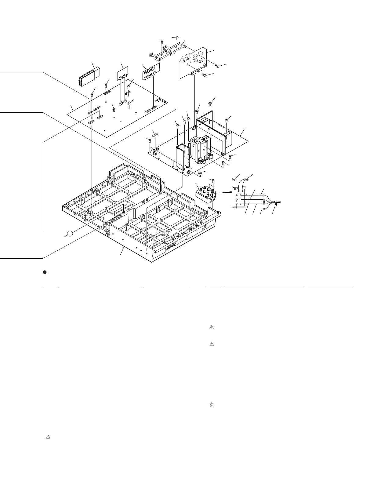
1. EXPLODED VIEWS AND PARTS LIST
NOTES:• Parts marked by "NSP" are generally unavailable because they are not in our Master Spare Parts List.
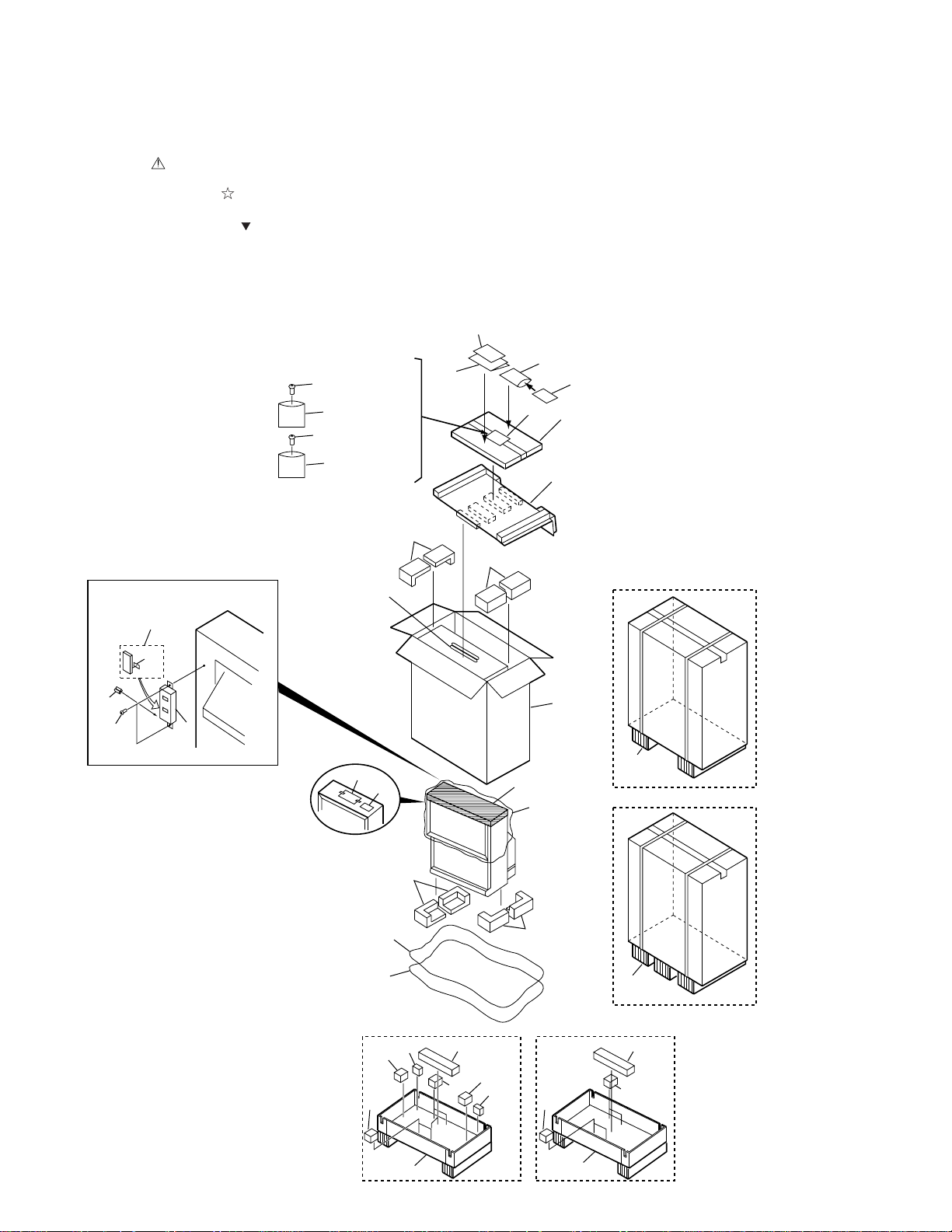
1.1 PACKING
The mark found on some component parts indicates the importance of the safety factor of the part.
•
Therefore, when replacing, be sure to use parts of identical designation.
Parts marked by are important parts which relate in X-rays radiation.
•
If any of these parts need to be replaced, always replace with specified parts.
Screws adjacent to mark on the product are used for disassembly.
•
For POWER SUPPLY ASSY, AWV1558 is used, but for serving, AWV1565 is supplied.
•
AWV1565 is the same as AWV1558 of which X-ray protection and high voltage sections have been adjusted and these
adjusted parts are covered with the shield cases. Therefor, AWV1565 need not be adjusted.
2
(Rear View)
28
29
27
26
30
31
×12
31
×8
(PRO-100)
7
32
×12
32
×8
(PRO-100)
7
(PRO-200)
(PRO-200)
12,13
16
17
14
4
15
35
34
1 (5,6)
8
PRO-100
11
33
PRO-200
3
9
10
18
22
23
19
33
PRO-100
24
22
22
25
20
21
PRO-200
22
22
25
2423
22
2
Page 3
(1) PACKING PARTS LIST
PRO-200, PRO-100
Mark No. Description Part No.
1 Card Board Case (60) See Contrast table (2)
2 Attention Card ARM1108
3 Operating Instructions (English) ARB1515
NSP 4 Literature Bag AHG1222
NSP 5 Acrylic Panel (60) See Contrast table (2)
6 Acrylic Caution Card ARH1152
NSP 7 Wrapper Bag AHG1076
8 Card Board Spacer (60) See Contrast table (2)
9 Upper Pad L AHA2067
10 Upper Pad R AHA2068
11 Upper Carton (60P) See Contrast table (2)
12 Frame Cover Assy (60) See Contrast table (2)
13 Frame Cover V Assy (60) See Contrast table (2)
NSP 14 Vinyl Sheet 60 Upper See Contrast table (2)
NSP 15 Packing Sheet (60) See Contrast table (2)
16 CONVER Attention Card ARM1139
17 Caster Caution Card See Contrast table (2)
18 Under Pad L AHA2069
19 Under Pad R AHA2070
NSP 20 Packing Sheet 60L See Contrast table (2)
Mark No. Description Part No.
21 Vinyl Sheet 60 Under See Contrast table (2)
22 Cushion F See Contrast table (2)
NSP 23 Cusion D See Contrast table (2)
NSP 24 Cusion C AHA2076
25 Under Carton (60P) See Contrast table (2)
26 Remote Contorol Unit AXD1430
(CU-SD104)
27 Battery Cover AZN7327
NSP 28 Alkaline Dry Cell Battery AEX1018
(LR6,AA)
29 Special Screw ABA1239
30 CU Packing Case AHC1019
31 Screw ABA1226
32 Screw BMZ40P100FZK
33 Carton Runner Pad (60P) See Contrast table (2)
NSP 34 Warranty Card EL ARY1026
NSP 35 Poly Bag AHG1285
(2) CONTRAST TABLE
PRO-200/KUXC/CA and PRO-100/KUXC/CA are constructed the same except for the following :
Mark No.
NSP 5 Acrylic Panel (60) Acrylic Panel (51) AAK2633 AAK2632
11 Upper Carton (60P) Upper Carton (51P) AHD2962 AHD2961
PRO-200/KUXC/CA PRO-100/KUXC/CA PRO-200/KUXC/CA PRO-100/KUXC/CA
1 Card Board Case (60) Card Board Case (51) AHB1154 AHB1152
8 Card Board Spacer (60) Card Board Spacer (51P) AHB1162 AHB1172
Symbol and Description Part No.
Remarks
12 Frame Cover Assy (60) Frame Cover Assy (51) AAP1521 AAP1520
13 Frame Cover V Assy (60) Frame Cover V Assy (51) AAP1557 AAP1560
NSP 14 Vinyl Sheet 60 Upper Vinyl Sheet XL AHG1233 AHG1095
NSP 15 Packing Sheet (60) Packing Sheet (50,45) AHG1230 AHG1120
17 Not used Caster Caution Card Not used ARM1117
NSP 20 Packing Sheet 60L Packing Sheet AHG1235 AHG1156
21 Vinyl Sheet 60 Under Vinyl Sheet MS AHG1234 AHG1258
NSP 22 Cushion F Cushion E AHA2211 AHA2081
NSP 23 Cushion D Not used AHA2077 Not used
25 Under Carton (60P) Under Carton (51P) AHD2967 AHD2966
33 Carton Runner Pad (60P) Carton Runner Pad (51P) AHA2202 AHA2201
3
Page 4
PRO-200, PRO-100
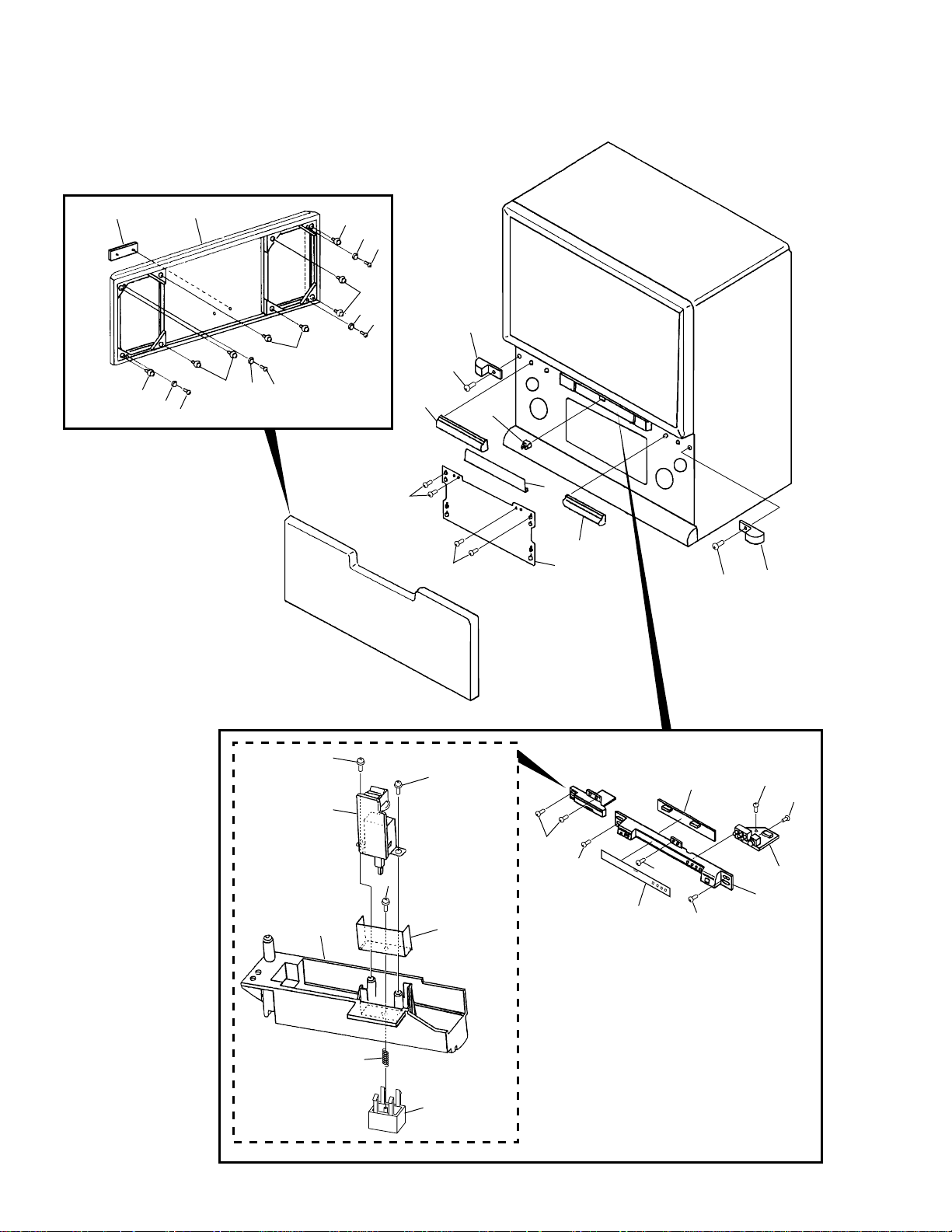
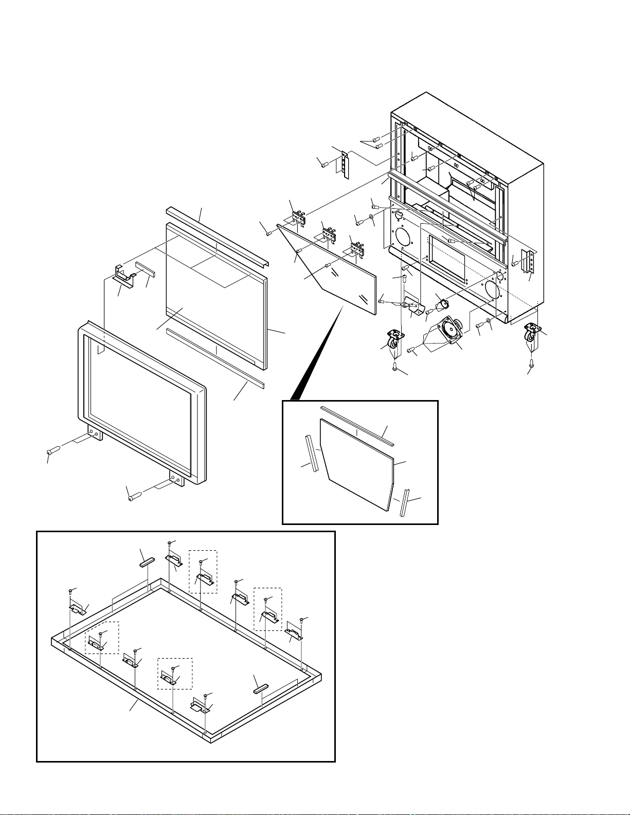
1.2 FRONT VIEW (1/2)
2
3
1
3
3
4
4
5
5
3
4
5
3
4
5
8
7
6
7
12
10
9
7
11
6
7
13
16
14
20
13
21
13
15
19
7
7
18
7
7
22
22
23
17
4
Page 5
(1) FRONT VIEW (1/2) PARTS LIST
Mark No. Description Part No.
1 Grille (60) See Contrast table (2)
2 ELITE Badge AAM1076
NSP 3 Catcher A ANZ-241
4 Magic Tape AEC1394
5 Screw BYC35P160FZK
6 Side Cover See Contrast table (2)
7 Special Screw ABA1240
8 Side Panel Assy (60L) See Contrast table (2)
9 Side Panel Assy (60R) See Contrast table (2)
10 Door Assy AAN1413
11 Blind Plate AMM2577
12 Catcher F2M AEC1609
13 Screw APZ30P080FZK
14 MAIN SW Assy AWZ6114
NSP 15 Front Shield ANK1502
16 Sub Panel Assy AMB2556
17 Front Panel Assy AMB2614
18 Control Sheet AAK2715
19 FRONT CONTROL Assy AWZ6299
20 Coil Spring ABH1099
PRO-200, PRO-100
21 Power Knob AAD4090
22 Screw ABZ30P080FZK
23 FRONT INPUT Assy AWZ6118
(2) CONTRAST TABLE
PRO-200/KUXC/CA and PRO-100/KUXC/CA are constructed the same except for the following :
Mark No.
PRO-200/KUXC/CA PRO-100/KUXC/CA PRO-200/KUXC/CA PRO-100/KUXC/CA
1 Grille (60) Grille (51) AMM2584 AMM2585
6 Side Cover Side Cover AMR2743 AMR2573
8 Side Panel Assy (60L) Side Panel Assy (51L) AMB2583 AMB2584
9 Side Panel Assy (60R) Side Panel Assy (51R) AMB2616 AMB2615
Symbol and Description Part No.
Remarks
5
Page 6
PRO-200, PRO-100
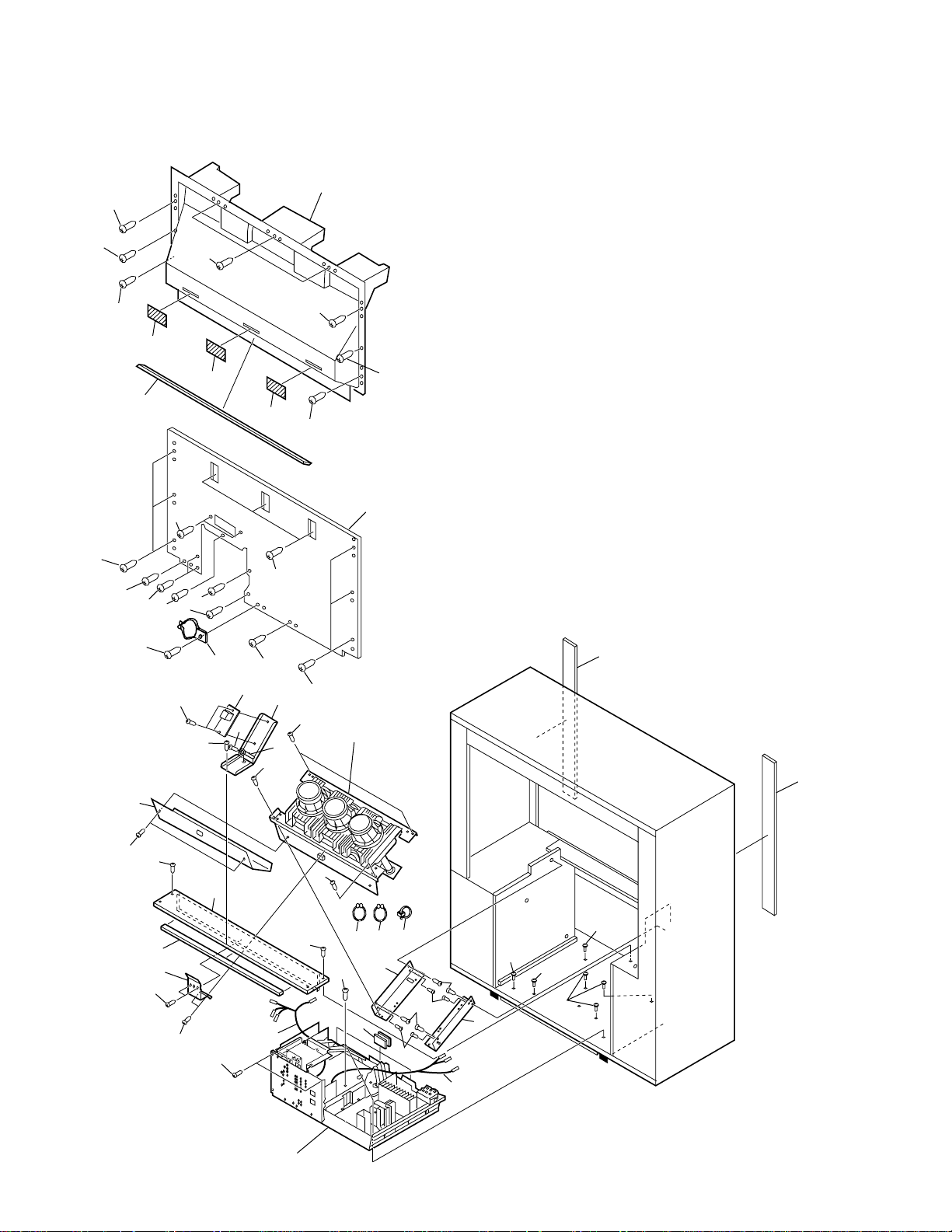
1.3 FRONT VIEW (2/2)
31
4
1
10
9
8
30
2
8
5
6
8
8
3
15 (PRO-100)
14 (PRO-200)
11
27
28
7
11
10
17
10
10
10
10
10
12
11
13
10
27
28
8
9
14
18
16
32
29
20
18
24
8
23
PRO-200 Only
8
22
8
22
8
PRO-200 Only
22
22
PRO-200 Only
8
22
8
8
PRO-200 Only
8
22
22
24
8
25
21
20
16
8
19
26
6
Page 7
(1) FRONT VIEW (2/2) PARTS LIST
Mark No. Description Part No.
1 Lenticular Sheet 60 See Contrast table (2)
2 Almi. Frame (60) See Contrast table (2)
3 Fresnel (60PRO) See Contrast table (2)
NSP 4 Upper Cabinet Metal ANG2000
NSP 5 Mirror Upper Stay L ANG2004
NSP 6 Mirror Upper Stay C ANG2006
NSP 7 Mirror Upper Stay R ANG2005
8 Screw BYC40P160FMC
NSP 9 Screen Side Fitting ANG1993
10 Special Screw ABA1240
11 Special Screw ABA1244
12 Tweeter APT1004
13 Cone Speaker APV1021
14 Caster AMR2547
15 Caster See Contrast table (2)
PRO-200, PRO-100
NSP 17 CRT Front Holder See Contrast table (2)
NSP 19 Under Screen Metal B ANG2009
NSP 22 Upper Screen Metal B ANG2002
NSP 23 Under Screen Metal A ANG2003
NSP 25 Upper Screen Metal A ANG2001
16 Special Screw ABA1126
18 M5 Screw ABA1189
20 Mirror Frame V See Contrast table (2)
21 Mirror (60A) See Contrast table (2)
24 Frame Cushion P AEC1634
26 Screen Frame Assy (60) See Contrast table (2)
27 Screw BYC35P160FZK
28 Washer AEC1394
29 Mirror Frame H See Contrast table (2)
30 Screen Holder Low (60P) See Contrast table (2)
31 Spacer AEC1769
32 Screen Spacer (60) See Contrast table (2)
(2) CONTRAST TABLE
PRO-200/KUXC/CA and PRO-100/KUXC/CA are constructed the same except for the following :
Mark No.
15 Caster Caster Not used AMR2863
NSP 17 CRT Front Holder CRT Front Holder ANG2120 ANG2121
PRO-200/KUXC/CA PRO-100/KUXC/CA PRO-200/KUXC/CA PRO-100/KUXC/CA
1 Lenticular Sheet 60 Lenticular Sheet 51 AMR3084 AMR3083
2 Almi. Frame (60) Almi. Frame (51) ANG2287 ANG2286
3 Fresnel (60PRO) Fresnel (51PRO) AMR3086 AMR3085
Symbol and Description Part No.
Remarks
20 Mirror Frame V Mirror Frame V ANG2007 ANG2084
21 Mirror (60A) Mirror AMR2739 AMR2852
26 Screen Frame Assy (60) Screen Frame Assy (51) AAP1515 AAP1514
29 Mirror Frame H Mirror Frame H ANG2008 ANG2083
30 Screen Holder Low (60P) Screen Holder Low (51P) AAP1590 AAP1589
32 Screen Spacer (60) Screen Spacer (51) AEC1768 AEC1767
7
Page 8
PRO-200, PRO-100
1.4 REAR VIEW
22
24
22
23
22
28
26
22
22
22
25
25
25
22
9
9
29
1
2
2
29
30
37
36
37
33
22
3
32
22
3
34
23
27
21
Refer to
"1.6 CRT BLOCK".
21
2
4
5
20
20
6
7
8
3
9
Refer to
"1.5 CHASSIS BLOCK".
10
4
141315
11
19
31
16
8
12 8
12
18
20
20
17
8
Page 9
(1) REAR VIEW PARTS LIST
PRO-200, PRO-100
Mark No. Description Part No.
NSP 1 Tray (PLS) AMR2563
2 Screw ABZ30P120FZK
3 Special Screw ABA1244
4 Screw ABA1124
NSP 5 Back Cover Panel See Contrast table (2)
6 Back Cover Cushion See Contrast table (2)
NSP 7 CRT Rear Holder ANG2119
8 Special Screw ABA1240
9 Screw ABA1149
10 Wire Harness ADX2458
11 Screw BYC40P350FZK
12 Screw PMB50P200FZK
13 Screw ACZ40P080FMC
NSP 14 Purse Lock S AEC1261
15 Purse Lock AEC1540
16 Nylon Binder AEC-093
NSP 17 CRT Stand Holder (L) ANA1516
18 8P Housing Wire (J12) ADX2257
19 Wire Holder AMR2832
20 Special Screw ABA1234
Mark No. Description Part No.
21 Screen Cushion 60 See Contrast table (2)
22 Screw BYC35P160FZK
23 Screw PYC40T140FZB
24 Mirror Case (51) AME2296
25 Blind Sheet AEC1622
26 Mirror Case Cushion AEC1627
27 Rear Cover AMM2893
28 Screw BMZ40P100FZK
29 Special Screw ABA1235
NSP 30 Cabinet Wire Holder AEC1263
NSP 31 CRT Stand Holder (R) ANA1517
NSP 32 IR Receiver Fixing Metal ANG1958
33 IR RECEIVER Assy AWZ6297
34 Binder AEP-215
35 • • • • •
36 Screw ABA1239
37 Screw BBZ30P080FZK
(2) CONTRAST TABLE
PRO-200/KUXC/CA and PRO-100/KUXC/CA are constructed the same except for the following :
Mark No.
NSP 5 Back Cover Panel Back Cover Panel AMM2664 AMM2663
21 Screen Cushion 60 Screen Cushion 51 AEC1617 AEC1612
PRO-200/KUXC/CA PRO-100/KUXC/CA PRO-200/KUXC/CA PRO-100/KUXC/CA
6 Back Cover Cushion Back Cover Cushion 60 AEC1656 AEC1626
Symbol and Description Part No.
Remarks
9
Page 10

PRO-200, PRO-100
1.5 CHASSIS BLOCK
13
2
13
13
48
45
48
14
14
47
48
48
14
1
16
5
46
14
15
14
14
15
4
3
14
6
18
14
1117
7
14
20
20
21
21
22
49
23
50
22
22
22
14
A
12,14
14
8
13
14
15
9
19
18
10
10
Page 11
28
26
14
14
14
25
14
14
27
14
31
14
14
13
14
PRO-200, PRO-100
29
30
18
18
13
13
13
14
43
32
A
44
CHASSIS BLOCK PARTS LIST
Mark No. Description Part No.
1 CONVERGENCE Assy AWZ6098
2 FULL CINEMA CONVER Assy AWZ6108
3 TUNER 2 Assy AWZ6296
4 3D Y/C Assy AWZ6117
5 AV I/O Assy AWZ6320
6 P IN P Assy AWZ6101
7 P IN P SELECTOR Assy AWZ6120
8 RF Switch AXF1088
9 Y/C SELECTOR Assy AWZ6100
10 AUDIO Assy AWZ6298
32
35 36
FBT
37 38
39 40 41 42
• Rear View of Focus VR
34
33
14
Mark No. Description Part No.
26 TV Front End System Unit AXF1084
27 A CONNECTOR Assy AWZ6106
NSP 29 PCB Holder H ANG2056
31 Fuse (FU102 : 500mA/125V) AEK1010
34 Focus VR (VR1) ACX1096
28 TUNER • VIDEO Assy AWZ6330
30 VM Assy AWZ6105
32 Screw VBZ30P200FMC
33 Shield Case ANK1510
35 1P Lead Wire (J3) ADX2231
11 D CONNECTOR Assy AWZ6119
12 BNC Cap AMR2314
13 Screw ABZ30P120FZK
14 Screw BBZ30P140FZK
15 Binder AEP-215
NSP 16 PCB Frame ANG2045
17 B CONNECTOR Assy AWZ6103
18 Rivet AEC-441
19 Rear Panel ANC2311
20 Hexagonal Duct Nut ABN-087
21 Bushing AEC1661
22 Screw BBZ30P100FZK
23 AC Power Cord ADG1177
24 • • • • •
25 IQ SELECTOR Assy AWZ6329
36 4P Housing Wire (J2) ADX2230
37 1P Lead Wire (J5) ADX2233
38 1P Lead Wire (J6) ADX2236
39 1P Lead Wire (J8) ADX2238
40 1P Lead Wire (J4) ADX2232
41 1P Lead Wire (J7) ADX2237
42 Nylon Binder AEC-093
43 POWER SUPPLY Assy AWV1565
NSP 44 Chassis AMA1011
45 COMPONENT Assy AWZ6300
NSP 46 Sub Chassis ANA1577
47 Sub Panel ANC2310
48 Screw BBZ30P080FZK
49 Ferrite Core ATX1033
50 Screw ABZ30P160FZK
11
Page 12
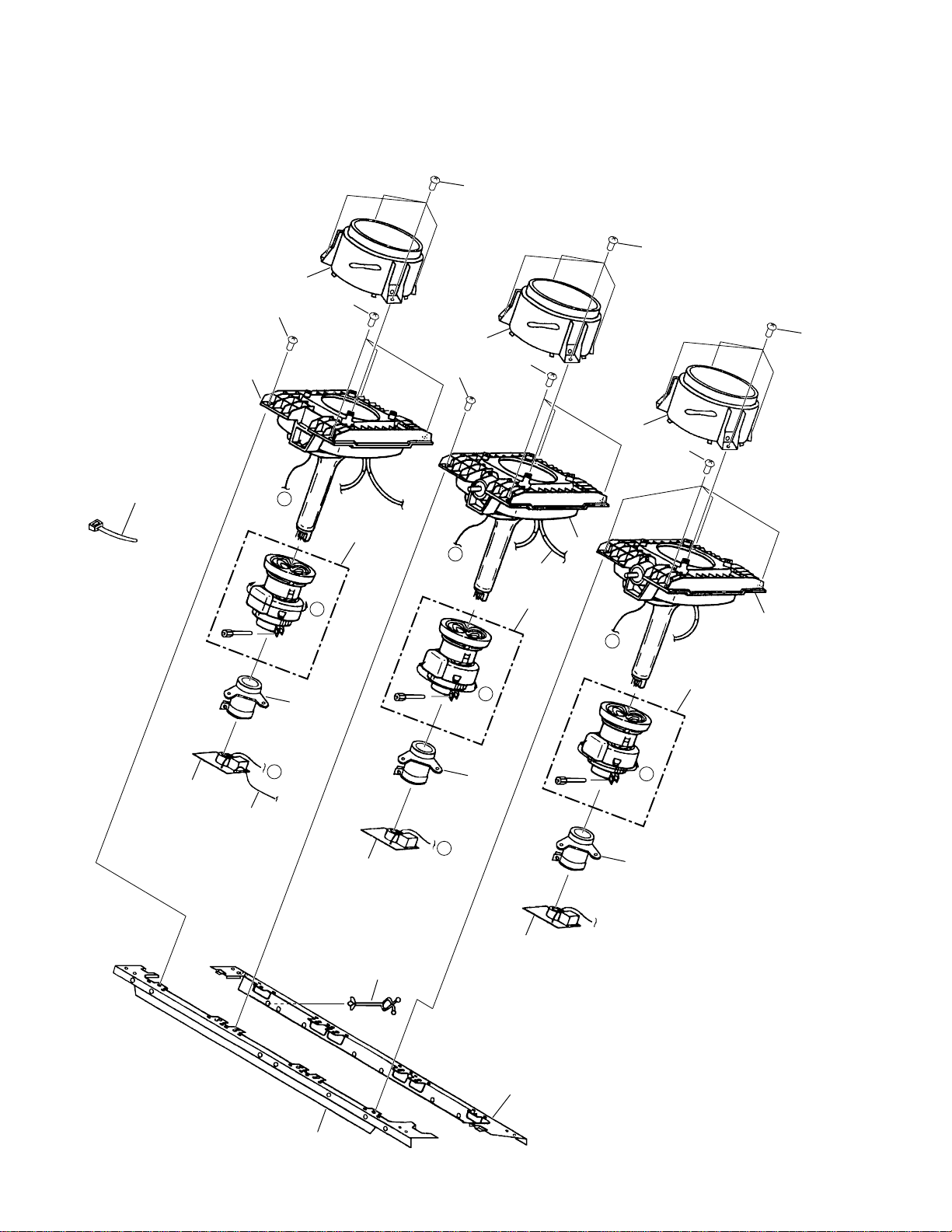
PRO-200, PRO-100
1.6 CRT BLOCK
5
5
1
6
2
7
1
6
7
1
7
5
22
15
18
A
9
B
a
12
A
16
13
B
10
a
17
3
8
4
C
11
a
14
12
19
20
21
Page 13
(1) CRT BLOCK PARTS LIST
Mark No. Description Part No.
1 Lens Assy AMR2833
2 CRT Service Assy 60 (R) See Contrast table (2)
3 CRT Service Assy (G) AWY1394
4 CRT ServiceAssy 60 (B) See Contrast table (2)
5 Special Screw ABA1244
6 Screw FBT40P120FZK
7 Screw (Steel) ABA1168
8 Anode Cable (J1) ADY1012
9 Deflection Yoke (L1) ATL1127
10 Deflection Yoke (L2) ATL1127
11 Deflection Yoke (L3) ATL1127
12 VM Coil (L4) ATL1123
13 VM Coil (L5) ATL1123
14 VM Coil (L6) ATL1123
15 R.CRT DRIVE Assy AWZ6110
16 G.CRT DRIVE Assy AWZ6111
17 B.CRT DRIVE Assy AWZ6112
18 VM Wire Harness (J13) ADX2229
NSP 19 Lead Clamper M AEC1611
NSP 20 CRT Rear Frame (60) See Contrast table (2)
PRO-200, PRO-100
NSP 21 CRT Front Frame (60) See Contrast table (2)
22 Nyron Binder AEC-093
(2) CONTRAST TABLE
PRO-200/KUXC/CA and PRO-100/KUXC/CA are constructed the same except for the following :
Mark No.
NSP 20 CRT Rear Frame (60) CRT Rear Frame (51) ANA1520 ANA1518
NSP 21 CRT Front Frame (60) CRT Front Frame (51) ANA1515 ANA1513
PRO-200/KUXC/CA PRO-100/KUXC/CA PRO-200/KUXC/CA PRO-100/KUXC/CA
2 CRT Service Assy 60 (R) CRT Service Assy 51 (R) AWY1406 AWY1403
4 CRT Service Assy 60 (B) CRT Service Assy 51 (B) AWY1407 AWY1405
Symbol and Description Part No.
Remarks
13
Page 14
PRO-200, PRO-100
2. CONTRAST OF MISCELLANEOUS PARTS
NOTES:•Parts marked by "NSP" are generally unavailable because they are not in our Master Spare Parts List.
PCB ASSY
PRO-200/KUXC/CA, PRO-100/KUXC/CA, PRO-119/KUXC and PRO-99/KUXC are constructed the same except
for the following :
Mark Symbol and Description
The mark found on some component parts indicates the importance of the safety factor of the part.
•
Therefore, when replacing, be sure to use parts of identical designation.
When ordering resistors, first convert resistance values into code form as shown in the following examples.
•
Ex.1 When there are 2 effective digits (any digit apart from 0), such as 560 ohm and 47k ohm (tolerance is shown by J=5%,
and K=10%).
560 Ω→56 × 10
47k Ω→47 × 10
1
→ 561 ........................................................ RD1/4PU 5 6 1 J
3
→ 473 ........................................................ RD1/4PU 4 7 3 J
0.5 Ω→R50 ..................................................................................... RN2H R 5 0 K
Ex.2 When there are 3 effective digits (such as in high precision metal film resistors).
5.62k Ω→ 562 × 10
Parts marked by are important parts which relate in X-rays radiation.
•
1
→ 5621 ...................................................... RN1/4PC 5 6 2 1 F
1 Ω→1R0 ..................................................................................... RS1P
1 R 0
K
If any of these parts need to be replaced, always replace with specified parts.
Parts marked by × are important parts which relate in X-rays radiation. If a failure occurs in any of these parts, replace the
•
printed circuit board assembly where the relevant part has already been adjusted as a working component. Do not replace the
actual part itself. If any part marked by
× is replaced, there is danger of being exposed to X-rays.
Part No.
PRO-119/KUXC, PRO-200/KUXC/CA,
Remarks
PRO-99/KUXC PRO-100/KUXC/CA
TUNER • VIDEO ASSY AWV1559 Not used
NSP VIDEO BLOCK A1V1559 Not used
NSP UCOM BLOCK A2V1559 Not used
NSP TUNER BLOCK A3V1559 Not used
NSP PRE-AUDIO BLOCK A4V1559 Not used
NSP TUNER • VIDEO ASSY Not used AWV1705
TUNER • VIDEO ASSY Not used AWZ6330
NSP VIDEO BLOCK Not used A1Z6330
NSP UCOM BLOCK Not used A2Z6303
NSP TUNER BLOCK Not used A3Z6303
NSP PRE-AUDIO BLOCK Not used A4Z6303
IR RECEIVER ASSY Not used AWZ6297
NSP AV I/O ASSY AWV1560 AWV1677 AWV1701
AV I/O ASSY AWZ6099 AWZ6295 AWZ6320
AV I/O BLOCK A1Z6099 A1Z6295 A1Z6320
NSP P IN P ASSY AWV1561 AWV1678
EXT SP ASSY AWZ6102 Not used
NSP TUNER 2 • ISC ASSY AWV1562 Not used
ISC ASSY AWZ6104 Not used
NSP TUNER 2 BLOCK A1Z6104 Not used
NSP ISC BLOCK A2Z6104 Not used
FULL CINEMA MUTE ASSY AWZ6107 Not used
NSP TUNER 2 ASSY Not used AWV1679
TUNER 2 ASSY Not used AWZ6296
NSP TUNER 2 BLOCK Not used A1Z6104
NSP SR BLOCK Not used A2Z6296
NSP AUDIO ASSY AWV1563 AWV1680
AUDIO ASSY AWZ6109 AWZ6298
FRONT CONTROL ASSY AWZ6113 AWZ6299
IR RECEIVER ASSY AWZ6115 Not used
SUB RECEIVER ASSY AWZ6116 Not used
RECEIVER ELEMENT ASSY AWZ6073 Not used
RECEIVER CIRCUIT ASSY AWZ6074 Not used
(∗1)
(∗2)
or
NSP COMPONENT ASSY Not used AWV1704
COMPONENT ASSY Not used AWZ6300
IQ SELECTOR ASSY Not used AWZ6329
FULL SINEMA MUTE BLOCK Not used A1Z6301
IQ SELECTOR BLOCK Not used A2Z6329
14
Page 15
PRO-200, PRO-100
Mark No. Description Part No.
TUNER•VIDEO ASSY
TUNER BLOCK
A3Z6303 and A3V1559 are constructed the same
except for the following :
Mark Symbol and Description
Q1201,Q1301 XDC124ES DTC124ES
Part No.
A3V1559 A3Z6303
Remarks
PRE-AUDIO BLOCK
A4Z6303 and A4V1559 are constructed the same
except for the following :
Mark Symbol and Description
CN1351 (2P PIN JACK) AKB1151 AKB1265
CN1353 (1P PIN JACK) AKB1111 AKB1267
Note :
A table isn't inserted because there is much difference from PRO119 in VIDEO Block (A1Z6330) and UCOM Block (A2Z6303) of PRO200 and PRO-100.
Refer to the "PCB PARTS LIST".
Part No.
A4V1559 A4Z6303
Remarks
AV I/O ASSY
AV I/O BLOCK (∗1)
A1Z6295 and A1Z6099 are constructed the same
except for the following :
Mark Symbol and Description
Q1526 Not used 2SC1740S
D1508 Not used HSS104-02
R1532,R1549 Not used RD1/4PU473J
CN1501 (3P PIN JACK) AKB1137 AKB1264
CN1502 (12P PIN JACK) AKB1114 AKB1263
AV I/O BLOCK (∗2)
A1Z6320 and A1Z6099 are constructed the same
except for the following :
Mark Symbol and Description
CN1501 (3P PIN JACK) AKB1137 AKB1264
CN1502 (12P PIN JACK) AKB1114 AKB1263
Part No.
A1Z6099 A1Z6295
Part No.
A1Z6099 A1Z6320
Remarks
Remarks
Mark No. Description Part No.
PCB PARTS LIST
TUNER • VIDEO ASSY
A
F
SEMICONDUCTORS
IC804 AT24C08-10PC
IC1301 CXA1734S
IC403 MC14011BCP
IC1353 MC14066BCP
IC802 MC34064P
IC1203 NJM7809FA
IC402 PA0030
IC801 PD5473B
IC401 TA8845BN
IC803 TC4094BP
IC1351 UPC1853CT-01
Q1202,Q1206,Q1208,Q1213,Q1302 2SA933S
Q1351,Q1352,Q1357-Q1359 2SA933S
Q403,Q404,Q406,Q409-Q411 2SA933S
Q416-Q418,Q423-Q426,Q444 2SA933S
Q447,Q801,Q805,Q812,Q821 2SA933S
Q823-Q827,Q832 2SA933S
Q1204,Q1205,Q1207,Q1209-Q1211 2SC1740S
Q1303,Q1304,Q1354-Q1356 2SC1740S
Q1360-Q1363,Q1366,Q401,Q402 2SC1740S
Q405,Q407,Q408,Q412-Q415 2SC1740S
Q419-Q421,Q427-Q442 2SC1740S
Q445,Q446,Q450-Q453 2SC1740S
Q802,Q803,Q806-Q809 2SC1740S
Q813,Q814,Q816,Q817 2SC1740S
Q819,Q820,Q822 2SC1740S
Q422 2SC2235
Q1212 2SC2878
Q1203,Q804 2SD880
Q818 2SJ460
Q443 2SK117
Q1201,Q1301 DTC124ES
D488,D489 1SS244
D1207-D1211,D1352,D1353 HSS104-02
D1355-D1366,D402-D404 HSS104-02
D411-D413,D426-D432 HSS104-02
D435,D436,D439,D440 HSS104-02
D443,D444,D448,D455,D456 HSS104-02
D462,D464-D466,D468 HSS104-02
D471-D474,D476-D479 HSS104-02
D482,D483,D487,D490,D491 HSS104-02
D801,D802,D804,D805 HSS104-02
D807-D809,D811,D812 HSS104-02
D816-D818,D867-D871,D873 HSS104-02
D889,D891 HSS104-02
D408 HZS9C3L
D441 MA723
D1301,D1302,D409,D410 MTZJ15
D415,D416,D420-D424 MTZJ15
D437,D438,D442,D445-D447 MTZJ15
D449-D454,D457-D461,D463 MTZJ15
D467,D469,D470,D475,D831 MTZJ15
D843,D845,D847 MTZJ15
D803 MTZJ5.1B
D1201,D1204,D414,D806,D810 MTZJ6.8
15
Page 16

PRO-200, PRO-100
Mark No. Description Part No.
D813,D819-D830,D832-D842 MTZJ6.8
D844,D846,D848-D866,D872 MTZJ6.8
D878-D884 MTZJ6.8
D401 RD2.2ESB1
D1203 RD33ESB3
D1354 RD4.3ESB3
D1351 RD4.7ESB3
D1202 RD5.6ESB3
D405-D407,D417-D419,D425 S5688G
D433,D434 S5688G
COILS
L416 LINE FILTER ATF-163
L417 COIL ATH1046
L407,L412 LAU100J
L409 LAU101J
L410 LAU150J
L1201-L1203,L1301,L802-L805 LAU2R2K
L408 LAU390K
L411 LAU3R9J
L401-L403 LAU4R7J
L404,L405 LAU560J
L801 LAU8R2K
CAPACITORS
C1311 (3.3µF/DC50V) ACH1128
C1304 (10µF/DC50V) ACH1129
TC801 CERAMIC TRIMMER ACM-020
C403 CCCCH100D50
C831 CCCCH101J50
C426,C428,C429 CCCCH121J50
C425,C427,C441,C475,C478 CCCCH151J50
C477,C844 CCCCH820J50
C452 CCCSL100D50
C1208,C463,C832,C833 CCCSL101J50
C1252,C453,C468,C470 CCCSL121J50
C451 CCCSL180J50
C814,C829,C830 CCCSL221J50
C817 CCCSL270J50
C442,C443,C450 CCCSL330J50
C455 CCCSL390J50
C1210,C847-C850 CCCSL470J50
C480 CCCSL560J50
C469,C471 CCCSL680J50
C1390 CEANP100M50
C1213,C432,C456,C457,C460 CEAS100M50
C467,C811 CEAS100M50
C449,C827,C839 CEAS101M10
C408,C420,C458 CEAS101M25
C465,C482 CEAS102M16
C806 CEAS102M35
C1305,C1310,C1360,C410,C412 CEAS1R0M50
C418,C419,C431,C804,C810 CEAS1R0M50
C820-C823,C835,C840 CEAS1R0M50
C1215,C1385 CEAS220M50
C1356,C1359,C1370-C1373 CEAS2R2M50
C1387-C1389,C406,C407,C413 CEAS2R2M50
C472 CEAS2R2M50
C854 CEAS330M35
C1374 CEAS331M16
Mark No. Description Part No.
C1364,C1366 CEAS3R3M50
C1221,C1369,C1376,C1379 CEAS470M25
C415,C416,C423,C430,C435 CEAS470M25
C454,C473,C819,C846,C851 CEAS470M25
C855 CEAS470M25
C424 CEAS471M10
C1217 CEAS471M16
C1307,C1316,C1319,C1320,C1322 CEAS4R7M50
C417,C462 CEAS4R7M50
C812,C837 CEASR10M50
C826 CEASR22M50
C1312,C434 CEASR47M50
C1204,C1212,C1303 CEHAQ100M50
C1205,C808 CEHAQ101M10
C1247,C1251,C1318 CEHAQ101M25
C807 CEHAQ1R0M50
C1245,C1249 CEHAQ331M16
C1203,C1220 CEHAQ470M25
C1206 CEHAQ471M16
C1301,C1306,C1315,C1317 CEHAQ4R7M50
C1308 CFTXA224J50
C1211,C440,C825,C838 CKCYB102K50
C479 CKCYB103K50
C1365,C1367 CKCYB152K50
C1302,C1309 CKCYB222K50
C1253 CKCYB391K50
C843 CKCYB471K50
C405 CKCYB472K50
C815 CKCYB561K50
C1201,C1202,C1207,C1216,C1224 CKCYF103Z50
C1246,C1248,C1321,C1357,C409 CKCYF103Z50
C421,C436-C439,C802,C803 CKCYF103Z50
C805,C809,C813,C818,C828 CKCYF103Z50
C834,C842,C845,C852 CKCYF103Z50
C1368,C1375,C1377,C433,C459 CKCYF473Z50
C466,C474,C483,C816 CKCYF473Z50
C1386,C841 CQMA102J50
C402 CQMA103J50
C1352,C1361,C1363,C401,C422 CQMA104J50
C461,C801 CQMA104J50
C411 CQMA123J50
C404 CQMA183J50
C1353 CQMA222J50
C1355,C1358 CQMA223J50
C1314 CQMA272J50
C414 CQMA392J50
C1313 CQMA473J50
C1354,C476 CQMA681J50
C1362,C1378 CQMA682J50
C444,C445 CQMA683J50
C1351 CQMA823J50
RESISTORS
R1389 RD1/2LMF330J
R464,R465,R470-R472 RD1/2PM100J
R466 RD1/2PM120J
R515 RD1/2PM221J
R1206,R468,R469,R474 RD1/2PM271J
R1207,R1209 RD1/2PM681J
R679 RD1/2PM6R8J
R809,R958,R959 RD1/4LMF3R9J
R1305 RN1/4PC4302F
R1307 RN1/4PC6202F
16
Page 17
PRO-200, PRO-100
Mark No. Description Part No.
R458 RS1MMF220J
R1353 RS1MMF470J
R1259 RS2LMF1R0J
R641 RS2LMF4R7J
R1205,R1261 RS2MMF220J
R830 RS3LMF100J
VR1201 (4.7kΩ) ACP1042
VR801 VRTS6VS153
Other Resistors RD1/4PU J
OTHERS
1203,1204 COAXIAL CABLE ADE-082
J1203 3P HOUSING WIRE ADX2240
CN1351 2P PIN JACK AKB1265
CN1353 1P PIN JACK AKB1267
1205 HEAT SINK ANH-880
X801 CERAMIC RESONATOR ASS1015
X402 CERAMIC RESONATOR ASS1019
X401 CRYSTAL RESONATOR ASS1091
CN405 10P PLUG KM200IA10
CN406 15P PLUG KM200IA15
CN404 19P PLUG KM200IA19
CN805 7P PLUG KM200IA7
CN801 8P PLUG KM250MA8B
CN804 8P PLUG KM250MA8R
CN401 9P PLUG KM250MA9R
CN802 10P SOCKET KP250NA10
CN809 12P SOCKET KP250NA12
CN1202,CN803 15P SOCKET KP250NA15
CN808 3P SOCKET KP250NA3
CN811,CN814 4P SOCKET KP250NA4
CN1355,CN813 5P SOCKET KP250NA5
CN1354 7P SOCKET KP250NA7
CN1203,CN403,CN807 8P SOCKET KP250NA8
CN402 9P SOCKET KP250NA9
1201 TV FRONT END SYSTEM UNIT AXF1084
DL406 DELAY LINE ATN1014
FRONT CONTROL ASSY
H
F
SEMICONDUCTORS
IC3881 PD5136
Q3881 2SA933S
Q3882 2SC1740S
D3882 AEL1152
D3881,D3883,D3885,D3886 HSS104-02
D3884 MTZJ3.0
PC3881 P1241-09
SWITCHES
S3881-S3892 ASG1034
CAPACITORS
C3884,C3885 CCDSL221J50
C3881 CEJA100M35
C3886 CEJA2R2M50
C3882 CEJA330M25
C3883 CFTXA104J50
Mark No. Description Part No.
RESISTORS
R3886 RD1/2PM561J
R3887 RD1/2PMF820J
VR3901 (47kΩ) ACP1045
Other Resistors RD1/4PU J
OTHERS
3881 LED HOLDER AMR1733
X3881 CERAMIC RESONATOR ASS1043
CN3881 5P PLUG KM250MA5
TUNER2 ASSY
K
F
SEMICONDUCTORS
Q2105,Q2107,Q2109,Q2214 2SA1162
Q2102 2SC1740S
Q2101 2SC2235
Q2103,Q2104,Q2106,Q2108,Q2207 2SC2712
Q2209,Q2210 2SC2712
D2104,D2105 1SS226
D2212,D2214,D2217,D2225 1SS352
D2102 RD33MB
D2101 RD5.6MB
D2226 RD6.8MB
COILS
L2101-L2103 LAU2R2K
CAPACITORS
C2120 CCSQSL121J50
C2121 CCSQSL391J50
C2114 CCSQSL470J50
C2102,C2105,C2106 CEHAQ100M50
C2103 CEHAQ101M10
C2109,C2119 CEHAQ331M16
C2101,C2107,C2108,C2212 CEHAQ470M25
C2104,C2118 CEHAQ471M16
C2115 CKSQYF102Z50
C2110-C2113,C2116,C2117,C2213 CKSQYF103Z50
C2221 CKSQYF103Z50
C2220 CKSQYF222Z50
RESISTORS
R2102 RD1/2PM271J
R2103,R2104 RD1/2PM681J
R2126 RD1/4PU562J
R2101 RS2MMF220J
VR2101 (2.2kΩ) ACP1041
Other Resistors RS1/10S J
OTHERS
CN2206 2P MINI JACK AKN1061
CN2203 12P PLUG KM250NA12L
CN2201 3P PLUG KM250NA3L
CN2101 8P PLUG KM250NA8L
C3888 CKCYB472K50
C3887 CKCYF473Z50
17
Page 18

PRO-200, PRO-100
Mark No. Description Part No.
AUDIO ASSY
Q
F
SEMICONDUCTORS
IC2901 LA4280-P
Q2903 2SA933S
Q2902,Q2904 2SC1740S
Q2901 2SD1276A
D2922 BR3371XJ30A
D2902-D2904,D2906,D2908-D2921 HSS104-02
D2927 HSS104-02
D2905,D2907 MTZJ6.8
D2931 RD2.0ESB
D2901 RD5.6ESB3
D2928 RD9.1ESB3
COILS
L2903 LINE FILTER ATF-163
L2901,L2902 ATH-133
CAPACITORS
C2923,C2924 (3.3µF/DC63V) ACH1127
C2906,C2913 CCCSL151J50
C2908,C2911 CEHAQ100M50
C2909 CEHAQ101M25
C2940 CEHAQ220M50
C2922 CEHAQ221M10
C2920,C2921 CEHAQ222M35
C2907,C2910 CEHAQ330M50
C2925 CEHAQ470M25
C2901,C2905 CEHAQ471M50
C2912,C2917 CKCYB102K50
C2936,C2937 CKCYB471K50
C2902 CKCYB561K50
C2903,C2926 CKCYF103Z50
C2914-C2916 CKCYF473Z50
C2918,C2919 CQMA124J50
RESISTORS
R2921,R2923 RD1/2PM152J
R2916,R2917 RD1/4LMF100J
R2912,R2914 RD1/4LMF2R2J
R2904 RN1/4PC2702F
R2903 RN1/4PC6201F
R2951 RS3LMF151J
R2950 RT10PZ4R7K
Other Resistors RD1/4PU J
OTHERS
2911 PLATE SPRING ANG1569
2902 HEAT SINK ANH-880
CN2902 8P PLUG KM250MA8
CN2903 5P PLUG KM250NA5L
CN2904 7P PLUG KM250NA7L
Mark No. Description Part No.
IQ SELECTOR ASSY
S
F
SEMICONDUCTORS
IC2003,IC2004 MC14066BF
IC2009 TC4013BF
IC2002 TC74HC04AF
IC2001 TC74HC4040AF
IC2005 TC74HC4538AF
Q2001 2SA1162
Q2002,Q2004-Q2011 2SC2712
D2038-D2041 1SS226
D2005-D2010,D2012-D2018 1SS352
D2020-D2022,D2024-D2034 1SS352
D2036,D2037 1SS352
D2001-D2004,D2023,D2035 RD6.8MB
CAPACITORS
C2005 CCSQCH151J50
C2002,C2004,C2007,C2011,C2015 CEAT470M25
C2001,C2003,C2006,C2010,C2016 CKCYF473Z50
C2008 CQMA471J50
C2009 CQPA362J2A
RESISTORS
R2037 RD1/2LMF3R9J
R2007 RN1/16SE1202D
R2033 RS1/16S100J
R2015,R2021,R2022,R2041,R2043 RS1/16S101J
R2045,R2047,R2052-R2062 RS1/16S101J
R2001,R2002,R2004,R2005 RS1/16S102J
R2009,R2010,R2012-R2014,R2018 RS1/16S102J
R2020,R2032,R2040,R2063,R2064 RS1/16S102J
R2023,R2028-R2030,R2034,R2051 RS1/16S103J
R2016 RS1/16S153J
R2019 RS1/16S183J
R2038,R2039 RS1/16S221J
R2024,R2027,R2035,R2036 RS1/16S222J
R2049,R2050 RS1/16S223J
R2006,R2008,R2011 RS1/16S272J
R2017 RS1/16S333J
R2025 RS1/16S471J
R2026,R2031,R2042,R2044,R2046 RS1/16S472J
R2048 RS1/16S472J
R2003 RS1/16S513J
VR2001 (100kΩ) ACP1046
VR2002 VRTS6VS103
OTHERS
2003 CABLE HOLDER AKT1011
CN2002 15P SOCKET KP200IA15L
CN2001 7P SOCKET KP200IA7L
18
Page 19

PRO-200, PRO-100
Mark No. Description Part No.
IR RECEIVER ASSY
AB
F
CAPACITORS
C9002 CCCSL121J50
C9001 CEAS101M10
RESISTORS
All Resistors RD1/4PU J
OTHERS
CN9001 3P PLUG KM250MA3
REMOTE RECEIVER UNIT GP1U28X
COMPONENT ASSY
AC
F
SEMICONDUCTORS
IC7001 AN5867K
IC7004 BA7655AF
IC7003 CXA1315M
IC7002 NJM7809FA
Q7003,Q7013,Q7014,Q7024,Q7025 2SA1162
Q7027-Q7030,Q7032,Q7033 2SA1162
Q7001,Q7002,Q7004-Q7012 2SC2712
Q7015-Q7023,Q7026,Q7031,Q7034 2SC2712
D7018,D7019 1SS226
D7001-D7017 1SS352
D7023 RD5.1MB
D7022 RD7.5MB
Mark No. Description Part No.
R7123 RS1/16S103J
R7047,R7071,R7101 RS1/16S104J
R7007,R7031,R7045,R7060,R7061 RS1/16S152J
R7067,R7068 RS1/16S152J
R7075 RS1/16S183J
R7098 RS1/16S203J
R7070,R7081,R7087 RS1/16S222J
R7005,R7006,R7018,R7019,R7029 RS1/16S223J
R7043,R7066,R7118-R7120,R7125 RS1/16S223J
R7128,R7131 RS1/16S242J
R7097 RS1/16S243J
R7010,R7020,R7022,R7074 RS1/16S272J
R7130 RS1/16S331J
R7012,R7024,R7058,R7059 RS1/16S332J
R7062,R7063,R7088 RS1/16S332J
R7028,R7065 RS1/16S333J
R7082 RS1/16S471J
R7049,R7078,R7084,R7121 RS1/16S472J
R7048 RS1/16S562J
R7064,R7073 RS1/16S681J
R7054,R7055,R7086,R7126,R7134 RS1/16S682J
R7100 RS1/16S683J
R7001,R7014,R7027 RS1/16S750J
R7122 RS1/2S221J
R7108 RS1MMF8R2J
OTHERS
DL7001,DL7002 DELAY LINE ATN1039
CN7002 3P PIN JACK AKB1268
7001 CABLE HOLDER AKT1011
CAPACITORS
C7034 CCSQCH470J50
C7010,C7011,C7016,C7027,C7028 CEAT100M50
C7032,C7033,C7035,C7037 CEAT100M50
C7021,C7023,C7026 CEAT101M10
C7022 CEAT101M25
C7001-C7006,C7015,C7019,C7020 CEAT470M25
C7031 CEAT470M25
C7024 CEAT4R7M50
C7008,C7009,C7012-C7014 CEATR10M50
C7007,C7017,C7018,C7025 CKSQYF473Z50
C7029,C7030,C7036 CKSQYF473Z50
RESISTORS
R7003 RN1/16SE1501D
R7008,R7016,R7021,R7026 RN1/16SE2201D
R7009 RN1/16SE3301D
R7113,R7116,R7133 RS1/16S0R0J
R7002,R7004,R7011,R7015,R7017 RS1/16S101J
R7023,R7030,R7032-R7038,R7040 RS1/16S101J
R7044,R7052,R7053,R7056,R7057 RS1/16S101J
R7069,R7079,R7080,R7083 RS1/16S101J
R7091-R7093,R7102-R7107 RS1/16S101J
R7109-R7112,R7117,R7124,R7127 RS1/16S101J
R7132,R7135 RS1/16S101J
R7039,R7046,R7050,R7051,R7085 RS1/16S102J
R7089,R7090 RS1/16S102J
R7013,R7025,R7041,R7042,R7072 RS1/16S103J
R7076,R7077,R7094-R7096,R7099 RS1/16S103J
19
Page 20
1
S
K
C
O
PRO-200, PRO-100
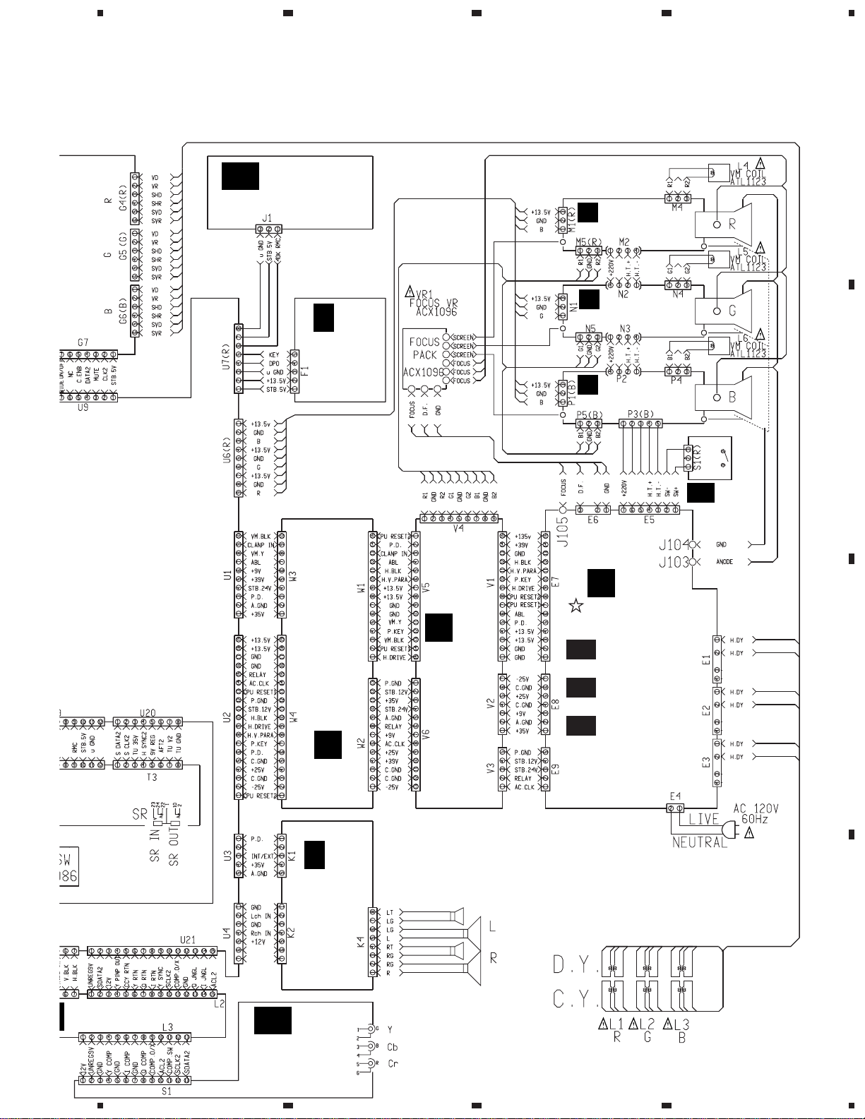
3. SCHEMATIC DIAGRAM
3.1 OVERALL WIRING DIAGRAM
A
C
Y/C SELECTOR
ASSY
(AWZ6100)
B
B
F
AV I/O ASSY
AWZ6295 : 1 to some
AWZ6320 : most assy
If necessory, see the Service Information.
B-a
B-b
AV I/O BLOCK
F(1/2):
(2/2):
PORT EXP. BLOCK
23
T
FULL
E
FRONT
INPUT
ASSY
(AWZ6118)
CINEMA
CONVER
ASSY
(AWZ6108)
U
CONVERGENCE ASSY
(AWZ6098)
A
F
TUNER • VIDEO AS
(AWZ6330)
A-a
A-b,c
A-d
A-e
4
(1/4):
F(2/4):
F(3/4):
(4/4):
TUNER BLOCK
VIDEO BLOC
UCOM BLOCK
PRE-AUDIO BLO
B CONNECTOR ASSY
C
M
(AWZ6103)
D
P IN P SELECTOR
ASSY (AWZ6120)
P IN P ASSY
O
(AWZ6101)
O-a
(1/3):
P IN P BLOCK
O-b
(2/3):
AUTO SG BLOCK(1/2)
O-c
(3/3):
AUTO SG BLOCK(2/2)
D CONNECTOR ASSY
N
D
(AWZ6119)
3D Y/C ASSY
P
(AWZ6117)
TUNER 2 ASSY
K
F
(AWZ6296)
S
F
IQ SELECT
(AWZ6329)
20
1234
Page 21
5
3
V
678
PRO-200, PRO-100
Note : When ordering service parts, be sure to refer to "EXPLODED VIEWS and PARTS LIST" or "PCB PARTS LIST".
IR RECEIVER
F
AB
SSY
ASSY
(AWZ6297)
H
F
FRONT
CONTROL
ASSY
(AWZ6299)
V
R CRT DRIVE ASSY
(AWZ6110)
W
G CRT DRIVE ASSY
(AWZ6111)
X
B CRT DRIVE ASSY
(AWZ6112)
A
B
MAIN SW
• VIDEO ASSY
0)
NER BLOCK
IDEO BLOCK
OM BLOCK
E-AUDIO BLOCK
Y
VM ASSY
(AWZ6105)
Z
POWER SUPPY
ASSY (AWV1565)
Z-a (1/3):
POWER SUPPLY BLOCK
Z-b (2/3):
DEFLECTION BLOCK
A CONNECTOR ASSY
NER 2 ASSY
WZ6296)
(AWZ6106)
L
Q
F
AUDIO
ASSY
(AWZ6298)
Z-c (3/3):
HIGH VOLTAGE BLOCK
AA
ASSY
(AWZ6114)
C
AC POWER CORD
ADG1177
IQ SELECTOR ASSY
F
(AWZ6329)
D
SPEAKER : APV1021
TWEETER : APT1004
F
AC
COMPONENT
ASSY
(AWZ6300)
5
6
7
L1–L3:
ATL1127
21
8
Page 22
1
V
D
A
Q
C
23
PRO-200, PRO-100
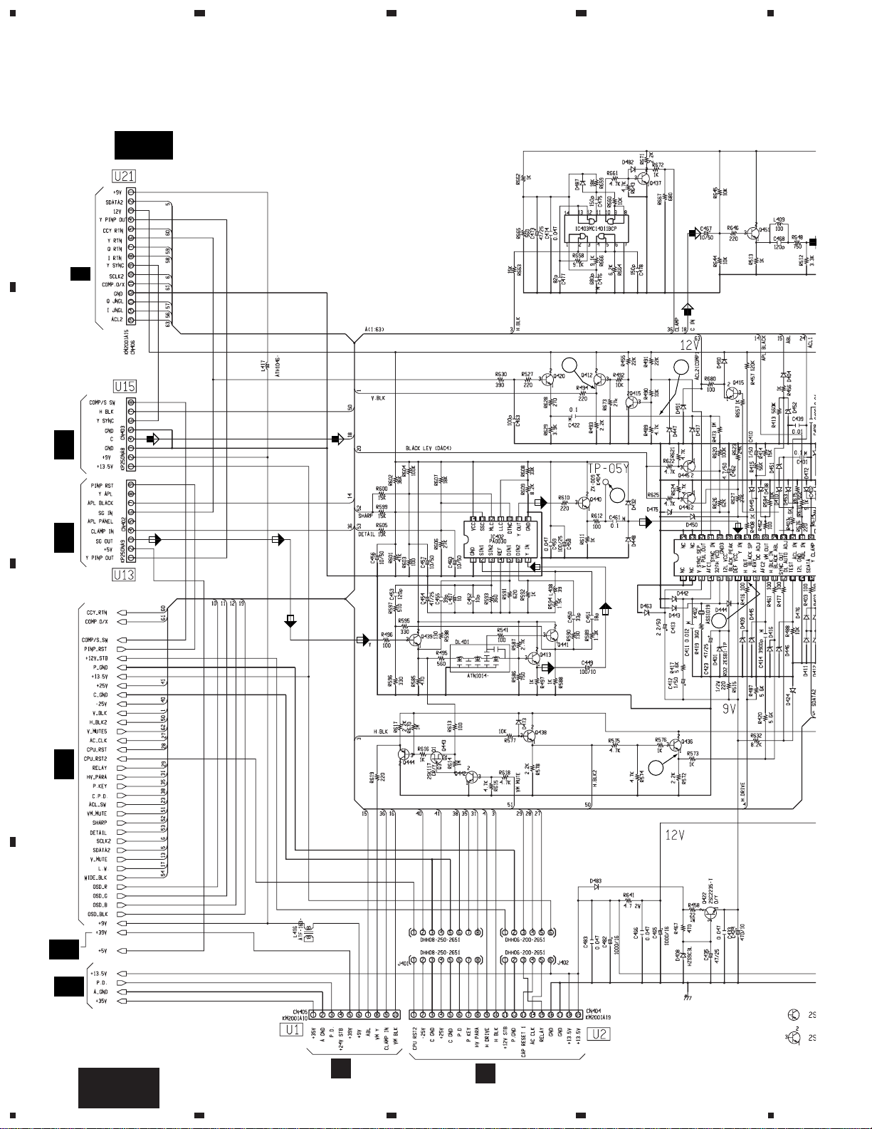
3.2 TUNER • VIDEO ASSY (2/4)
4
A
A-b,c
L2
F
S
B
H3
TUNER • VIDEO ASSY(2/4) (AWZ6330)
F
•VIDEO BLOCK
IC402 :
SHARPNESS
CONTROL
IC403, Q437 :
CLAMP PULSE GEN.
5
Q451 :
CHROM
IC401 :
3
O-a
4
H1
O-b
Q440 :
BUFFER
7
C
Q413,Q439,Q441 : BUFFER
F
A-d
Q438 :
H.BLK
BUFFER
6
A-a
D
A-e
Q422 :
+9V REGULATOR
22
A-b,c
1234
F
L W3
L W4
Page 23

Q451 :
CHROMA BPF
Q450 :
CHROMA AMP
5
678
PRO-200, PRO-100
Note : The waveforms are same as PRO-119 and PRO-99.
Refer to the service manual (ARP2936).
Q407–Q410,Q419,Q447,Q452 :
2
PEAK ACL
A
IC401 : VIDEO CHROMA AND
DEFLECTION PROCESSOR
(R)
(G)
(B)
Q434 :
I BUFFER
Q435 :Q BUFFER
(B)
9
(R)
(R)
(R)
(R)(R)(R)
B
10
(G)
(G)
11
(B)
(G)
(G)(G)
(R)
R
(G)
(B)
(B)
G
B
C
(B)
OR
Q411,Q424,Q426 :
(B)
V
W
X
8
RGB OUTPUT STAGE
M1
N1
P1
R
G
B
LINEAR WHITE
SIGNAL ROUTE:
: Y SIGNAL ROUTE
: C SIGNAL ROUTE
5
6
(R)
: R-Y SIGNAL ROUTE
(G)
: G-Y SIGNAL ROUTE
(B)
: B-Y SIGNAL ROUTE
(R)
: R SIGNAL ROUTE
(G)
: G SIGNAL ROUTE
(B)
: B SIGNAL ROUTE
7
A-b,c
F
8
23
D
Page 24

1
E
R
23
PRO-200, PRO-100
3.3 TUNER • VIDEO ASSY (3/4)
4
A
Q801–Q803,Q808 :
CPU RESET
H
F
F1
B
AB
K
F
J1
F
Q809 : INVERTER
T1
Q804 : +5V STB
REGULATOR
Q805–Q807 :
PEAK HOLD OF DISCHARG
IC801 :
SYSTEM CONT
MICROCOMPUT
K
F
T2
C
Q812 :
BUFFER
A-e
Q813,Q814 :
EXP. ENABLE HOLD
D
F
A-d
TUNER • VIDEO ASSY(3/4) (AWZ6330)
•UCOM BLOCK
A-a
O-a
H2
24
A-d
F
1234
Page 25

5
678
PRO-200, PRO-100
807 :
DISCHARGE
IC801 :
TEM CONTROL
ROCOMPUTER
Q820 : V MUTE INVERTER
Q819 :
RELAY
INVERTER
A
Q825–Q827 :
BUFFER
G7
U-a
Q821–Q824 :
Y–SIGNAL
DETECTOR
B
G3
U-a
IC802 : RESET IC
IC803 :
PORT EXPANDER
5
Q816,Q817 :
INVERTER
S
F
L1
6
P-a
D1
B-a
F
IC804 :
NON
VOLTAGE
MEMORY
A1
P-a
C
F
A-b
D2
D
A-d
7
8
F
25
Page 26

1
PRO-200, PRO-100
3.4 AV I/O ASSY (1/2)
A
BNC SOCKET
D
R1
23
C1
E
B-a
F
AV I/O ASSY(1/2) (AWZ6320)(AWZ6295)
• AV I/O BLOCK
IC1503:
VIDEO
SELECTOR
Q1511,
Q1512:
BUFFER
4
B
R2
D
Q1506:BUFFER
AWZ6295 ONLY
C
Q1501,Q1502,
Q1505,Q1515:
REC MUTE
A6
Q1507:VIDEO MUTE
IC1501:
AUDIO SELECTOR(Lch)
Q1518:
BUFFER
Q1508:
6dB AMP.
AWZ6295 ONLY
Q1520:
VIDEO
BUFFER
D
Q1503,Q1504,
26
Q1519:
AUDIO MUTE
B-a
F
1234
Q1516,Q1517:BUFFER
IC1504:
AUDIO SELECTOR(Rch)
Page 27

1
234
3.5 FRONT CONTROL and IR RECEIVER ASSEMBLIES
FRONT CONTROL ASSY
H
F
(AWZ6299)
A-d
F
U7
PRO-200, PRO-100
A
B
A-d
U7
IC3881 : KEY INPUT
MICROCOMPUTER
C
IR RECEIVER ASSY
F
AB
F
(AWZ6297)
D
H
1
2
3
F
AB
4
F
27
Page 28

1
PRO-200, PRO-100
3.6 TUNER 2 ASSY
23
4
A
TUNER 2 BLOCK
TV FRONT END SYSTEM UNIT
TUNER 2 ASSY (AWZ6296)
K
F
1
B
8.3V
Q2101 :
+5V REGULATOR
33.9V
Q2102 : 2SC1740S
Q2102 : +30V REGULATOR
34V
2.3V
8.9V
2.3V
Q2108, Q2109 :
AFT BUFFER
C
• ANTENNA SELECT : ANT A
• Video signal : NTSC color bar, 87.5% modulation
• Audio signal : 1kHz sinewave, ±25kHz deviation
• DC range (unless otherwise noted)
Voltage of TV FRONT END
Pin
Voltage (V)
Pin
Voltage (V)
1
V1:
D
0.1V PEAK DET.
28
1
6.925.5354–5–68.9758–933.2
10
–11–12–138.9144.6150162.3171.1184.6
TV Front End pin 18
V : 1V/div. H : 10µsec/div.
0.500V
K
TRIG1:
F
0.48V
10mS
T:
102.3mS
SAVE
-GND
TV Front End pin 18
1
V : 0.2V/div. H : 10µsec/div.
AC range
V1:
47.2mV
20mV PEAK DET.
1234
TRIG1:
42mV
10mS
T:
102.3mS
T3-pin 7
2
V : 1V/div. H : 10µsec/div.
V1:
0.344V
0.1V PEAK DET.
TRIG1:
0.33V
10mS
T:
102.3mS
SAVE
-GND
T3-pin 4
3
V : 1V/div. H : 20µsec/div.
V1:
0.012V
0.1V PEAK DET.
TRIG1:
0.28V
20mS
T:
204.6mS
SAVE
-GND
Page 29

5
678
PRO-200, PRO-100
A
Q2103 :
VIDEO AMP
3.1V
4.6V
0.2V
3.8V
Q2106, Q2107 :
H SYNC DET.
Q2104, Q2105 :
VIDEO BUFFER
8.9V
5.1V
C2120
120p
R2134
220
3.9V
C2121
390p
4.5V
2
SIGNAL ROUTE
: VIDEO SIGNAL ROUTE
3.1V
8.9V
3
37.7V
A-a
U20
B
SR BLOCK
A-d F
U18
C
A-d F
U19
D
F
29
K
5
6
7
8
Page 30

1
PRO-200, PRO-100
3.7 AUDIO ASSY
A
B
23
AUDIO ASSY (AWZ6298)
Q
F
IC2901 : POWER AMPLIFIER
4
A-e
U4
C
A-e
U3
Q2901, Q2902 : +35V REGULATOR
D
30
Q
F
1234
Page 31

5
678
PRO-200, PRO-100
A
SIGNAL ROUTE
: AUDIO SIGNAL ROUTE
SPEAKERS
B
Q2903, Q2904 : DC DET.
C
D
F
31
Q
5
6
7
8
Page 32

1
PRO-200, PRO-100
3.8 IQ SELECTOR ASSY
23
4
A
IQ SELECTOR ASSY (AWZ6329)
S
F
27
26
FULL CINEMA MUTE BLOCK
IC2005 : GENERATOR IC
21
for TRIMMING PULSE
20
B
18
IC2001 :
H PULSE COUNTER
19
28
27
4
8 7
6
C
10 11 12
D
5
13
14
IC2009 :
FLIP FLOP IC
15
17
16
32
S
F
1234
Page 33

5
678
PRO-200, PRO-100
IQ SELECTOR BLOCK
(I)(I)
25
(I)
(I)
(Q)
(Q)
(Q)
23
(Q)
(Q)
(Q) (Q) (Q)
22
(Q)
(I)
(Q)(Q)
Note :
The waveforms of to is the same as the thing of
1 21
FULL CINEMA assy of PRO-119 and PRO-99.
Refer to page 36 for waveforms of to .
24
(I)
22 28
(I)
A
AC F
(I)
(I) (I)
S1
B
(Q)(Q)(Q)
(I) (I) (I)
(Q)(Q)
(Q)(Q)
(I)
3
2
1
A-d F
U5
SIGNAL ROUTE
: Y SIGNAL ROUTE
(I)
: I SIGNAL ROUTE
(Q)
: Q SIGNAL ROUTE
A-b,c F
U21
C
D
F
33
S
5
6
7
8
Page 34

1
PRO-200, PRO-100
3.9 COMPONENT ASSY
A
23
4
AC
COMPONENT ASSY (AWZ6300)
F
2
(R)
(R)
(R)
(I)
(I)
4
6.3V
(I)
6.3V
(Q)
6.1V
2.1V
(I)
3.8V
(Q)
2.1V
2.1V
B
CR/P
CB/P
R
B
Y
(R)
(B)
(B)
3
(B)
(Q)
(B)
(Q)
5
4.4V
5.4V
4.4V
5.3V
9V
4V
(I)
6.7V
5.3V
5.3V
(Q)
(Q)
C
3.8V
SIGNAL ROUTE
: Y SIGNAL ROUTE
(R)
: R-Y SIGNAL ROUTE
(B)
: B-Y SIGNAL ROUTE
(I)
: I SIGNAL ROUTE
(Q)
: Q SIGNAL ROUTE
1
D
O (COMPONENT) : Low
X (COMPOSITE) : High
34
AC
F
1234
Page 35

5
678
PRO-200, PRO-100
L3
S F
A
(I)
(Q)
2.1V
8
3.8V
(Q)
(Q)
6.7V
9V
(I)
5.2V
(I)
(I)
(Q)
3V
(Q)
(I) (I)
(Q) (Q)
2.1V
9V
4V
(I)
5.3V
5.3V
(Q)
IC7002 : REGULATOR
4.6V
4.6V
2 - 3.25V
4.0V
6
(Q)
7
(Q)
4.0V
(Q)(I)(Q)(I)
(Q)
(I)
(I)
(I)
(Q)
B
IC7004 :
VIDEO AMP.
IC7003 :
8 bit D/A
CONVERTER
C
9
D
AC
5
6
7
8
F
35
Page 36

PRO-200, PRO-100
WAVEFORMS of IQ SELECTOR and COMPONENT ASSEMBLIES
IQ SELECTOR ASSY
S F
AC
COMPONENT ASSY
F
• Input signal : 100/0 100/0 color bar • Input signal : 100/0 100/0 color bar
IC2004-pin 4
22
V : 2V/div. H : 20µsec/div.
IC2004-pin 1
23
V : 2V/div. H : 20µsec/div.
IC2004-pin 8
24
V : 2V/div. H : 20µsec/div.
-GND -GND
-GND
IC2003-pins 4 and 11
27
V : 1V/div. H : 20µsec/div.
IC2003-pin 1
28
V : 1V/div. H : 20µsec/div.
-GND
C7005 – side
1
V : 200mV/div. H : 20µsec/div.
C7001 – side
2
V : 200mV/div. H : 20µsec/div.
C7003 – side
3
V : 200mV/div. H : 20µsec/div.
6
-GND
7
-GND
Q7015 Emitter
V : 1V/div. H : 20µsec/div.
Q7016 Emitter
V : 1V/div. H : 20µsec/div.
CN7001-pin 4
8
V : 1V/div. H : 20µsec/div.
-GND
IC2004-pin 11
25
V : 2V/div. H : 20µsec/div.
IC2003-pin 8
26
V : 1V/div. H : 20µsec/div.
-GND
-GND
-GND
C7011 – side
4
V : 1V/div. H : 20µsec/div.
C7010 – side
5
V : 1V/div. H : 20µsec/div.
-GND
-GND
-GND
Q7009 Emitter
9
V : 1V/div. H : 20µsec/div.
-GND
-GND
36
Page 37

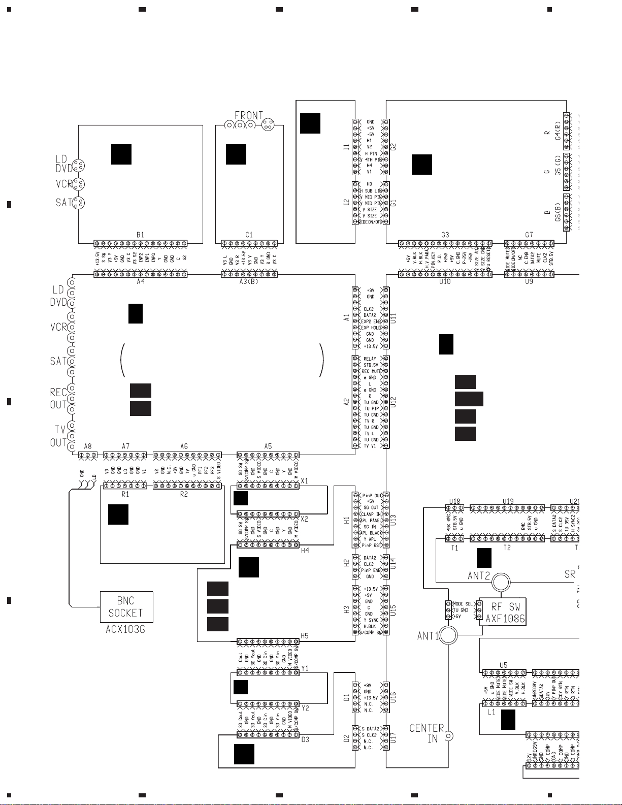
4. PCB CONNECTION DIAGRAM
NOTE FOR PCB DIAGRAMS :
1. Part numbers in PCB diagrams match those in the schematic
diagrams.
2. A comparison between the main parts of PCB and schematic
diagrams is shown below.
3. The parts mounted on this PCB include all necessary parts for
several destinations.
For further information for respective destinations, be sure to
check with the schematic diagram.
4. View point of PCB diagrams.
Symbol In PCB
Diagrams
Symbol In Schematic
Diagrams
Part Name
BCE
D
DGGSS
BCE
BCE
DGS
BCEBCE
BCE
Transistor
Transistor
with resistor
Field effect
transistor
Resistor array
3-terminal
regulator
Capacitor
Connector
P.C.Board
Chip Part
SIDE A
SIDE B
PRO-200, PRO-100
37
Page 38

1
Q
8
C
PRO-200, PRO-100
4.1 TUNER • VIDEO ASSY
23
4
T2
F
K
TUNER • VIDEO ASSY
A F
A
T3
F
K
H1
O
B
A1
B
A2
B
K
F
T1
U
G7
P
D1
L1
F
S S
H3
O
C
K2
F
Q
D
K1
F
Q
VR1201
38
IC1301
IC1203
Q1360
Q1361
Q1352
F
A
1234
IC1351
Q1201 Q1203
Q1304
Q1303 Q1301
Q1354-Q1356
IC1353
Q1357 Q1363 Q1362 Q1351
SIDE A
Q1204 Q1205 Q1210
Q1212 Q1213 Q1211
IC403 Q827 Q825
Q437 Q452 Q447 Q419 Q439 Q441 Q413
Q407-Q410
Q1206-Q1209
Q451 Q450
IC
I
Page 39

5
678
PRO-200, PRO-100
S
F
L1
S
F
L2
U
G3
P
D2
H
F
F1
AB
F
J1
A
B
O
W
V
X
H2
C
M1
N1
P1
10
-Q1209
1 Q450
9 Q441 Q413
IC802
IC402
Q442-Q444
IC803
Q812
Q434 Q435
Q421 Q440 Q412 Q420 Q446 Q445
5
IC801
Q415
Q814
Q813 Q821-Q824
Q830 Q831
Q422
6
Q817
IC804
Q816
Q411
Q436 Q438
VR801
Q819 Q832
Q423-Q427
Q433 Q432
7
Q809
Q402
Q404
(ANP1904-A)
Q805-Q807
Q801-Q803
Q826 Q808
Q820
Q430 Q417
Q414 Q403 Q428
Q416Q405 Q431 Q401
A
8
L
L
F
W4
D
W3
39
Page 40

1
PRO-200, PRO-100
4.2 FRONT CONTROL and IR RECEIVER ASSEMBLIES
A
FRONT CONTROL ASSY
H F
B
23
U7
F
A
4
AB F
C
D
IR RECEIVER ASSY
U7
F
A
(ANP1904-A)
40
SIDE A
F
H
AB
1234
F
Page 41

5
678
PRO-200, PRO-100
A
B
(ANP1850-C)
C
D
F
H
5
6
7
AB
8
F
41
Page 42

1
PRO-200, PRO-100
4.3 TUNER 2 ASSY
A
TUNER 2 ASSY
K F
23
4
Q2208
IC2201
Q2209
Q2211
B
Q2101
IC2202
Q2102
Q2214
Q2207
Q2105
IC2204
C
Q2104
Q2212
Q2213
Q2210
Q2205
VR2101
Q2204
Q2202
Q2201
Q2106
D
42
U18
F
A
F
K
1234
A
F
U19
A
SIDE A
F
U20
(ANP1905-A)
Q2215
Page 43

1
(
)
TUNER 2 ASSY
K F
234
PRO-200, PRO-100
A
B
C
Q2206
Q2103
Q2203
Q2107-Q2109
D
ANP1905-A
43
F
SIDE B
1
2
3
K
4
Page 44

1
PRO-200, PRO-100
4.4 AUDIO ASSY
A
Q F
AUDIO ASSY
23
4
Q2901Q2906Q2905Q2904
Q2902Q2951Q2952IC2901
B
C
SPEAKER
(ANP1850-C)
U4
F
D
A
A
F
U3
SIDE A
44
F
Q
1234
Page 45

1
4.5 IQ SELECTOR ASSY
234
PRO-200, PRO-100
A
IC2001 IC2002 IC2005Q2002
VR2002 VR2001
IQ SELECTOR ASSY
S F
U5
F
A
Q2011
Q2001
IC2009 IC2004
Q2005
Q2006 Q2010
Q2004
U21
F
A
IC2003
Q2007
Q2009
Q2008
(ANP1906-A)
AC
F
S1
B
IQ SELECTOR ASSY
S F
SIDE A
C
D
(ANP1906-A)
SIDE B
45
F
S
1
2
3
4
Page 46

1
PRO-200, PRO-100
4.6 COMPONENT ASSY
A
23
4
ACF
B
COMPONENT ASSY
IC7003
Q7019-Q7030
Q7009
IC7004
IC7001
Q7032-Q7034
Q7014
Q7013
Q7017
Q7018
Q7008
Q7035
Q7005-Q7007
C
Q7001-Q7004
Q7010
Q7011
Q7016 Q7015
Q7012 Q7031
IC7002
(ANP1906-A)
D
S
F
L3
SIDE A
46
AC
F
1234
Page 47

1
234
PRO-200, PRO-100
A
ACF
COMPONENT ASSY
B
C
(ANP1906-A)
D
SIDE B
47
AC
1
2
3
F
4
Page 48

1
PRO-200, PRO-100
4.7 AV I/O ASSY
A
B F
23
AV I/O ASSY
Q1526
Q1515
4
Q1505
R1532
D1508
R1549
B
Y1503Y1502
C
Q1519
Q1517
Q1516
Q1509
Q1520
Q1506
Q1507
Q1518
Q1508
Q1522
Q1511
Q1512
Q1513
Q1514 Q1551
Q1501
D
(ANP1847-C)
SIDE B
48
F
B
1234
Page 49

5. ADJUSTMENT
Attention: Only the part which is different from the PRO-119 and PRO-99 is mentioned.
For information other than that found in this manual, refer to the service manual (ARP2936) of the PRO-119 and PRO-99.
A point to give a mark has just become a change toward the PRO-119 and PRO-99.
Key Indication of The Remote Control Unit
PRO-200, PRO-100
AXD1430 (CU-SD104)
GV (Green, Vertical)
GH (Green, Horizontal)
BV (Blue, Vertical)
• Adjustment Items
ADJUSTMENT
RANGE OFFSET
Adjustment
Name
CUT-R
VOL0
Color
TINT
Contrast
Bright
Sharpness
Detail
VOL20
VOL30
DRV-G
VOL40
DRV-B
RH (Red, Horizontal)
RV (Red, Vertical)
BH (Blue, Horizontal)
Nu-
Adjustment
meric
Items
Keys
0
STATIC
1
SKEW
BOW
2
4TH BOW
3
SUB KEY
KEY
4
MID KEY
SUB PIN
MS PIN
5
4S PIN
SC PIN
PIN
6
MID PIN
4TH PIN
LIN
7
4TH LIN
8
SIZE
9
SUB LIN
VR : Adjust GH, GV with semifixed VR
Type
GH GV RH RV BH BV
OFFSET
CONVER
(Data Value)
VOL +
VOL –
: CUT-G
CH +
: CUT-B
CH –
(To output red, green and blue separately)
TV
LD
VIDEO 1
Note :
This unit can not operate by the ISC remote control unit (CU-SD100, etc.).
: To output red ON/OFF
: To output green ON/OFF
: To output blue ON/OFF
(The upper cover is opened)
original page 130
49
Page 50

PRO-200, PRO-100
Jigs and Measuring Instruments
Attention: A point to give a mark has just become a change toward the PRO-119 and PRO-99.
Remote control unit
(CU-SD104)
Color bar generator
(If possible, with component
video output)
CH1 CH2
(X) (Y)
Dual-trace oscilloscope
Remote control unit for servicing
AXD1352 (CU-SD076)
D. DC Voltmeter
Frequency counter
Screwdriver
LD Player
DVD Player
with component video output
Adjustment screwdriver
Monoscope
DVD Disc
(If possible, test disc with
color bar signal)
original page 131
50
Page 51

PRO-200, PRO-100
Attention: A point to give a mark has just become a change toward the PRO-119 and PRO-99.
Assembly Adjustment Location and Items
P IN P ASSY
A
F3002
F3001
VR3001VR3003
VR3002
TUNER • VIDEO ASSY
B
TP1301
TUNER 2 ASSY
C
E
VR1201
Q1205
TC801
VR2101
TP-05Y
VR801
TP-47B
TP-47G
TP-47R
IQ SELECTOR ASSY
E
Focus VR (VR1)
C
VR2002
B D
A
B
VR2001
B
G
R
Focus VR
E
Translucent paper such as tracing paper
Deflection
CRT assy G
Yoke (B)
CRT assy B
Deflection
Yoke
TP-BK TP-GK
B CRT DRIVE
Centering magnet
(Turn in either direction untill cross signal becomes white.)
assy
G CRT DRIVE
assy
MEASURING METHOD
Disconnect the FBT anode cable as shown below.
Measure at the point where the cable enters the FBT.
Caution : Take extra precaution when measuring the
voltage. High voltage are also present in
surrounding circuit boards. (CRT DRIVE
assy, POWER SUPPLY assy)
SERVICEMAN WARNING
Before removing the anode cable, turn off the power,
unplug the AC plug and let the unit discharge for
more than 1 minut.
Lens assy
(For Red)
Deflection
Yoke (G)
CRT assy R
Lens assy
(For Green)
Lens assy
(For Blue)
Deflection
Yoke (R)
R CRT DRIVE
assy
POWER SUPPLY ASSY
D
D109
Cathode
VR101
1
135V Power supply adjustment
2
Contrast coarse adjustment
3
Brightness adjustment (PIONEER's standard setting)
4
Deflection yoke lean adjustment
5
Screen center adjustment
6
Focus adjustment of lens assy
7
Focus VR adjustment
8
Vertical size adjustment
9
Horizontal size adjustment
10
Convergence adjustment
11
Test cross H-Center position assy
12
Tuner block adjustment
13
White balance adjustment
VR201
Pull straight up
Rubber
Cover
Holding the rubber cover firmly,
turn counterclockwise and
check that the lock has
been disengaged.
14
PIONEER's standard settings
15
Y-signal level adjustment of sub-picture
Note :
When reconnecting the cable, proceed in the
reverse order. After reconnecting, tug on the
cable to check that it is secure.
(adjustment for P IN P)
16
Tint adjustment of sub-picture
(adjustment for P IN P)
17
Color level adjustment of sub-picture
(adjustment for P IN P)
18
Write clock adjustment of sub-picture
(adjustment for P IN P)
19
Read clock adjustment of sub-picture
(adjustment for P IN P)
20
CINEMA MUTE adjustment
Anode Cable
FBT
original page 132
51
Page 52

PRO-200, PRO-100
Assembly Adjustment Location Guide
Attention: A point to give a mark has just become a change toward the PRO-119 and PRO-99.
1
135V power supply adjustment
7
Focus VR adjustment
8
If POWER SUPPLY ASSY
D
If TUNER • VIDEO ASSY
B
Reset the other items such
as the tuner preset channels,
convergence, etc. which
should be set by the user.
is repaired
is replaced
the video block
the UCOM block
is repaired
Vertical size adjustment
9
Horizontal size adjustment
10
Convergence adjustment
13
White balance adjustment
8
Vertical size adjustment
9
Horizontal size adjustment
10
Convergence adjustment
13
White balance adjustment
3
Brightness adjustment
White balance adjustment
13
PIONEER's standard adjustment
14
2
Contrast coarse adjustment
3
Brightness adjustment
11
Test-cross H-center position adjustment
14
PIONEER's standard settings
Refer to the
"Note (∗1)" as follows.
Refer to the
"Note (∗1)" as follows.
Refer to the
"Note (∗1)" as follows.
Refer to the
"Note (∗1)" as follows.
If TUNER 2 ASSY
C
If CONVERGENCE ASSY
If R, G or B CRT DRIVE ASSY
If P IN P ASSY
A
If CRT ASSY
the tuner block
the audio block
is replaced
is repaired or replaced
is repaired or replaced
is repaired or replaced
is repaired
is replaced
R, G, B or deflection yoke is replaced
12
Tuner block adjustment
No adjustment is required
All the above adjustments except for the test-cross H-center
position adjustment and tuner adjustment are required.
12 2
Video level adjustment
-2
10
Convergence adjustment
13
White balance adjustment
Y-signal level adjustment of sub-picture
15
TINT adjustment of sub-picture
16
17
Color level adjustment of sub-picture
18
Write clock adjustment
19
Read clock adjustment
Refer to the
"Note (∗1)" as follows.
No adjustment is required
4
Deflection yoke lean adjustment
5
Screen center adjustment
7
Focus VR adjustment
10
Convergence adjustment
13
White balance adjustment
14
PIONEER's standard settings
Refer to the
"Note (∗1)" as follows.
If LENS ASSY
If 3D Y/C ASSY
52
is replaced
is repaired or replaced
Focus adjustment of lens assy
6
Convergence adjustment
10
Check white balance. If the best screen is not obtained, adjust
13
White balance adjustment.
Refer to the
"Note (∗1)" as follows.
original page 133
Page 53

PRO-200, PRO-100
If IQ SELECTOR ASSY
E
If COMPONENT ASSY
If OTHER ASSY
Note (∗1):
For the adjustment of the steps 2,3,13 and 14, both adjustments of composite video signal and the component video signal is necessary.
• When the adjustment of the composite video signal is performed.
1. Input the COMPOSITE VIDEO signal to the VIDEO INPUT terminal.
2. Switch the video to the input of the composite video signal.
3. Perform the adjustment in accordance with the directions of the steps 2,3,13 and 14.
• When the adjustment of the component video signal is performed.
1. Input the COMPONENT VIDEO signal to the DVD COMPONENT VIDEO INPUT terminal.
But, when the adjustment of the color is not performed (steps 2, 3, 13, 14-1 and 14-2),
you may input the signal (without color burst and chroma) which took out Y signal from the composite signal to the Y input of component.
2. Switch the video to the input (LD/DVD) of the component video signal.
3. Perform the adjustment in accordance with the directions of the steps 2,3,13 and 14.
But, for the part with the directions of pressing the (DOWN) button, press the SWAP button to the substitute.
is repaired or replaced
is repaired or replaced
is repaired
is replaced
20
CINEMA MUTE adjustment
No adjustment is required
2
Contrast coarse adjustment
3
Brightness adjustment
13
11
White balance adjustment
14
14
PIONEER's standard settings
No adjustment is required
Perform the adjustment of
only component video signal.
Refer to the "Note (∗1)" as follows.
original page 133
Note : Be sure to adjust the composite video signal first.
53
Page 54

PRO-200, PRO-100
Factory ADJ Mode
Attention: A point to give a mark has just become a change toward the PRO-119 and PRO-99.
Select 1st FACTORY ADJ Mode
Start
LD position
TV POWER
"ON"
COMPONENT OFFSET
mode (SWAP)
Telop : Blue
Push the
switch with
thin rod.
Selecting the mode for adjustment operations.
Front panel
(MUTE)
2
OFFSET mode
( DOWN)
Telop : Blue
(MUTE)
MANUAL CONVER
mode (MENU SET)
Telop : White
Start
1st FAC
Range check mode
1
..........Start adjusting
..........Select 1st factory adjustment mode, then adjust
Normal
picture
Cyclically
2nd
FACTORY
ADJ mode
picture
(MENU ON)
Telop : Red
1st
FACTORY
ADJ mode
picture
(MUTE)
ADJUSTMENT MPX
mode (P IN P)
Telop : Magenta
The 2nd factory adjustment
mode is not used in the
adjustment.
TV STD OFFSET
mode ( UP)
Telop : Yellow
4
5
5
TV Standard Mode
Start
(UP)
1st FAC
3
ADJUSTMENT
Telop : Yellow
(MUTE)
TV STANDARD
a b
COLOR
AUTO CONVER mode
( LEFT)
Telop : White
1
2 3
4 5 6
–24
7 8 9 0
(MUTE)
(MUTE)
TEST mode
( RIGHT)
Telop : Green
a b
: COLOR 0
1
: TINT 0
2
: CONTRAST 0
3
: BRIGHT 0
4
: SHARPNESS 0
5
Set the Data value
VOL VOL
Not used in the
adjustment
original page 134
or
54
original page 136
Page 55

PRO-200, PRO-100
Attention: A point to give a mark has just become a change toward the PRO-119 and PRO-99.
Refer to the
Contrast coarse adjustment
2
"Note (∗1)" on page 53.
Start
(DOWN)
Brightness adjustment (PIONEER's standard settings)
3
1st FAC
ADJUSTMENT
Telop : Yellow
3
OFFSET
COLOR
Data value
VOL VOL
or
Start 1st FAC
Telop : 0
ADJUSTMENT
OFFSET
CONTRAST
Refer to the
"Note (∗1)" on page 53.
Cross hatch
0
TV CH
TV CH
(DOWN)
CUT-R
CUT-G
CUT-B
ADJUSTMENT
COLOR
Telop : Yellow
OFFSET
Data value
VOL VOL
4
VOL VOL
BRIGHT
or
0
Oscilloscope
G CRT DRIVE
or
assy
Cut off level
(190V DC)
TP-GK
GND
original page 137
55
Page 56

PRO-200, PRO-100
Test cross H-center position adjustment
11
Start
: ADJ CONVERGE
(DOWN)
(LD player)
TUNER • VIDEO ASSY
VR801
Adjust the position so that the
test cross is placed at the center
of the screen.
VR801
MENU 2
CC / XDS
AV MEMORY
CHANNEL SET UP
CONVERGENCE
SYSTEM IN / OUT
MENU 1
original page 152
-2 Video level adjustment
12
Start
P IN P
P IN P ANT. A CH9
ON / OFF
INPUT
CH
SHIFT
CH9
SWAP
EXIT
2
P IN P CH
or
CN2112
VR2101
TUNER 2 ASSY
not 75Ω terminal
VR2101
P IN P ANT. A CH9
ON / OFF
INPUT
CH
SHIFT
CH9
SWAP
EXIT
Oscilloscope
1Vp-p ± 0.10V
56
original page 153
Page 57

White balance adjustment
13
PRO-200, PRO-100
Refer to the
"Note (∗1)" on page 53.
Start
(DOWN)
PIONEER's standard settings
14
-1 Sharpness adjustment
14
1st FAC
Color bar signal
without color signal
Start 1st FAC
Telop : Blue
Adjust the DRV-G and DRV-B
so that the bright part of
the screen becomes white.
Adjust the CUT-R and CUT-B
so that the dark part of the
screen becomes gray.
(Don't move the screen
VR and CUT-G.)
889
: DRV-G
: DRV-B
9
CH
0
: CUT-R
0
CH
Refer to the
"Note (∗1)" on page 53.
Oscilloscope
: CUT-B
(DOWN)
5
-2 Color adjustment
14
Start 1st FAC
(DOWN)
1
OFFSET
OFFSET
"Multiburst"
TP-05Y
TUNER • VIDEO
ASSY
"Color bar"
Adjust the screen to optimum condition.
A : B = 4 : 6.2
A
B
500kHz 2MHz
original page 157
57
Page 58

PRO-200, PRO-100
-3 Tint adjustment
14
Start 1st FAC
(DOWN)
2
-4 Contrast adjustment
14
Start 1st FAC
OFFSETADJUSTMENT
TINT
DVD COMPONENT
VIDEO INPUT
DVD Player
"Color bar"
Adjust the screen to optimum condition.
In MENU
COLOR
TINT
14 14
–30 –15 +15 +30
2Steps 2Steps
2Steps
Example:
MENU FACTORY
2Steps
COLOR +17 +19
TINT –5
–10
∗ For the adjustment of -2 and -3.
When it does not have the color bar generator with component video output.
(However, make it finish the adjustment of composite video in advance.)
1. Prepare the DVD player with the component video output and the
Video software.
2. Input the component signal to the DVD COMPONENT VIDEO INPUT
of the TV, and input the composite signal to the VIDEO 1 INPUT.
3. Set the AV MEMORY of LD/DVD, VIDEO 1 to the STANDARD in the
normal use mode (It does not enter the FACTORY ADJ mode.)
4. Playback the Video software.
5. Adjust the value of COLOR and TINT of PICTURE of MENU1 with
seeing sometimes video of VIDEO 1 so that the video (color) of LD/DVD
becomes the same as the video of VIDEO 1.
6. The adjustment is complete, read the value of COLOR and TINT in the
MENU, and change it into the value in FACTORY in accordance with
the following table.
In FACTORY
7. Input the changed value to COLOR and TINT of the component offset
in the FACTORY ADJ mode. (End)
(DOWN)
3
CONTR
"Color bar"
Adjust the screen to optimum condition.
"Normal video signal"
OFFSETADJUSTMENT
At the TP-BK of the B. CRT DRIVE assy, check that the
signal is shaped as shown below .
A B
Shapely waveform Shapeless waveform
A
saturated
original page 158
58
Page 59

15
Y-signal level adjustment of sub-picture (adjustment for P IN P)
PRO-200, PRO-100
Start
MENU
• Set the FACTORY ADJ
mode to OFF and P IN P
function to ON.
• Supply the same signal
to both the main and sub
picture.
MENU
NEMU 1
P IN P
PICTURE
SOUND
SCREEN : NORMAL
MTS : MAIN
NEMU 2
TUNER•VIDEO
ASSY
TP-05Y
SET
P IN P ASSY
VR3002
" 100% White "
SET
SET
P IN P LD/DVD
ON/OFF
INPUT
LD/DVD
CH
SHIFT
SWAP
EXIT
Select input signal as same
input as the main-picture.
Main-picure signal
Sub-picture signal
Oscilloscope
16
TINT adjustment of sub-picture (adjustment for P IN P)
Start
MENU
• Set the FACTORY ADJ
mode to OFF and P IN P
function to ON.
• Supply the same signal
to both the main and sub
picture.
MENU
NEMU 1
P IN P
PICTURE
SOUND
SCREEN : NORMAL
MTS : MAIN
NEMU 2
SET
P IN P ASSY
VR3003
" Color-bar "
SET
SET
P IN P LD/DVD
ON/OFF
INPUT
LD/DVD
CH
SHIFT
SWAP
EXIT
Select input signal as same
input as the main-picture.
Adjust the TINT of the
sub-picture to optimum
condition.
original page 159
59
Page 60

PRO-200, PRO-100
17
Color level adjustment of sub-picture (adjustment for P IN P)
Start
MENU
• Set the FACTORY ADJ
mode to OFF and P IN P
function to ON.
• Supply the same signal
to both the main and sub
picture.
MENU
NEMU 1
P IN P
PICTURE
SOUND
SCREEN : NORMAL
MTS : MAIN
NEMU 2
SET
P IN P ASSY
VR3001
" Color-bar "
SET
SET
P IN P LD/DVD
ON/OFF
INPUT
LD/DVD
CH
SHIFT
SWAP
EXIT
Select input signal as same
input as the main-picture.
Adjust the color level of
the sub-picture to
optimum condition.
18
Write clock adjustment of sub-picture (adjustment for P IN P)
Start
MENU
• Set the FACTORY ADJ
mode to OFF and P IN P
function to ON.
• Supply the same signal
to both the main and sub
picture.
MENU
NEMU 1
P IN P
PICTURE
SOUND
SCREEN : NORMAL
MTS : MAIN
NEMU 2
SET
P IN P ASSY
F3002
SET
SET
P IN P LD/DVD
ON/OFF
INPUT
LD/DVD
CH
SHIFT
SWAP
EXIT
Select input signal as same
input as the main-picture.
Main-picture
AB
Sub-picture
A = B
60
Monoscope
original page 160
Page 61

19
Read clock adjustment of sub-picture (adjustment for P IN P)
PRO-200, PRO-100
Start
MENU
• Set the FACTORY ADJ
mode to OFF and P IN P
function to ON.
• Supply the same signal
to both the main and sub
picture.
MENU
NEMU 1
P IN P
PICTURE
SOUND
SCREEN : NORMAL
MTS : MAIN
NEMU 2
SET
P IN P ASSY
F3001
Monoscope
SET
SET
P IN P
ON/OFF
INPUT
CH
SHIFT
SWAP
EXIT
Select input signal as same
input as the main-picture.
C = D
Main-picture
Sub-picture
position 3
Sub-picture
position 4
CD
Center of main-picture
LD/DVD
LD/DVD
Sub-picture
position 2
Sub-picture
position 1
original page 161
20
CINEMA MUTE adjustment
Start
MENU
NEMU 1
P IN P
PICTURE
SOUND
SCREEN : NORMAL
MTS :
NEMU 2
VR2001
SET
IQ SELECTOR
ASSY
VR2002
SET
SET
NEMU 1
P IN P
PICTURE
SOUND
SCREEN : CINEMA
MTS :
NEMU 2
Switch the SCREEN mode
to CINEMA.
1
1
Turn VR2001, and make it indicate a black
2
part on the left of the screen, and adjust it
so that a black part may disappear exactly
from the screen.
Turn VR2002, and make it indicate a black
2
part on the right of the screen, and adjust it
so that a black part may disappear exactly
from the screen.
61
Page 62

PRO-200 PRO-100
6. IC INFORMATION
• The information shown in the list is basic information and may not correspond exactly to that shown in the schematic diagrams.
PD5473B (TUNER • VIDEO ASSY : IC801)
• TV Control µcom
Pin Arrangement
•
H.BLK
V.BLK
DPO
REMOTE
H.SYNC2
H.SYNC1
AFT2
NC
AFT1
CONV ENB
NC
PINP ENB
COMP.O/X
NC
SHARP
EXP ENB2
NC
EXP ENB1
KEY
TV A MUTE
OPT
PINP RST
NC
AVcc
CVIN
CNVSS
Xin
Xout
VSS
1 (H SYNC)
2 (V SYNC)
3 (P40/AD4)
4 (P41/INT2)
5 (P42/TIM2)
6 (P43/TIM3)
7 (P24/AD3)
8 (P25/AD2)
9 (P26/AD1)
10 (P27)
11 (P00/PWM4)
12 (P50/PWM7)
13 (P01/PWM5)
14 (P47)
15 (P02/PWM6)
16 (P51)
17 (P17/SIN)
18 (P32)
19 (P44/INT1)
20 (P56)
21 (P45/SOUT)
22 (P57)
23 (P46/SCLK)
24 (AVCC)
25 (HLF)
26 (RVCO)
27 (VHOLD)
28 (CVIN)
29 (CVNSS)
30 (XIN)
31 (XOUT)
32 (VSS)
(P52/R) 64
(P53/G) 63
(P54/B) 62
(P55/OUT1) 61
(P04/PWM0) 60
(P05/PWM1) 59
(P60) 58
(P06/PWM2) 57
(P61) 56
(P07/PWM3) 55
(P62) 54
(P20) 53
(P21) 52
(P22) 51
(P23) 50
(P10/OUT2) 49
(P65) 48
(P11/SCL1) 47
(P66) 46
(P12/SCL2) 45
(P67) 44
(P13/SDA1) 43
(P14/SDA2) 42
(P15/L1) 41
(P16/L2/INT3) 40
(P03) 39
(P30) 38
(P31) 37
(RESET) 36
(P64/OSC2/XCOUT) 35
(P63/OSC1/XCIN) 34
(VCC) 33
OSD.R
OSD.G
OSD.B
OSD.BLK
DATA2
NC
NC
LIN.W
V MUTE
DETAIL
V.M.MUTE
AC CLK
ROM RST
RELAY
NC
V O/X
TV V.MUTE
SCLK1
NC
SCLK2
CLK2
SDATA1
SDATA2
NC
CENTER O/X
S COMP SW
A MUTE
REC MUTE
RESET
OSC2
OSC1
VCC
Pin Function
I:Input Ci:CMOS input No:N ch open-drain output
Pin Function
•
.oNemaNniPO/InoitcnuF.oNemaNniPO/InoitcnuF
1KLB.H
2KLB.V 01BNEVNOCoNtuptuolangiselbane)B2000MP(CIrevnoC
3OPDI lortnoclevelOPDroftuptuoMWP11CN– noitcennocnoN
4ETOMERI
52CNYSHI
61CNYSHI
72TFAiC2renutroftupniegatlovgolanaTFA51PRAHSoNlortnoclevelSSENPRAHSroftuptuoMWP
8CN– noitcennocnoN612BNEPXEoN
IDSOroftupnilangis.cnyS
tupnilangislortnocetomeR
langisRSreenoiPehtrehpiceD
siti,semit8seunitnoccesm1niseslupCNYS
ynanehW.tsacdaorbasierehttahtdedrager
.tsacdaorbonsiereht
siti,semit8seunitnoccesm1niseslupCNYS
ynanehW.tsacdaorbasierehttahtdedrager
.tsacdaorbonsiereht
O:Output Co:CMOS output Ni:N ch open-drain input
91TFAiC1renutroftupniegatlovgolanaTFA
21BNEPNIPoNCIPniProftuptuolangiselbaneataD
noitpecer1renutroftupnitnuoc.cnyslatnoziroH
-H81ot21eraerehthcihwnisutatsehtnehW
31X/O.PMOCiN
tahtdedragersiti,semit6seunitnocsutatsrehto
noitpecer2renutroftupnitnuoc.cnyslatnoziroH
-H81ot21eraerehthcihwnisutatsehtnehW
41CN– noitcennocnoN
tahtdedragersiti,semit6seunitnocsutatsrehto
62
upninoitcetedlangistupniTNENOPMOC
tsixeTNENOPMOC:LTNENOPMOCoN:H
2CIrednapxetropfotuptuolangiselbaneataD
)O/I,1561CI(
Page 63

PRO-200, PRO-100
.oNemaNniPO/InoitcnuF.oNemaNniPO/InoitcnuF
71CN– noitcennocnoN14CN– noitcennocnoN
2
–noitcennocnoN
oCDSOroftuptuooediV
I
2
I
2
I
2
I
NO:L,FFO:H
NO:L,FFO:H
811BNEPXEoN
91YEKI
02ETUMAVToNFFO:L,NO:HtuptuoetumoiduaVT442KLCoC
12TPOiN.LotdexiFdesutoN542KLCSo/iN
22TSRPNIPoN
32CN– noitcennocnoN741KLCSo/iN
42ccVA– .V5+ylppAylppusrewopgolanA84ETUM.VVToNFFO:L,NO:HtuptuoetumoedivVT
52FLH
62OCVR 05CN– noitcennocnoN
72DLOHV–
82NIVCI )p-pV0.2(DCCroftupnilangisoediV25TSRMORoCEroftuptuoteseR
92SSVNCI SSVottcennoC35KLCCAiC
03niXI
13tuoXoC55LIATEDoNlortnoclevelLIATEDroftuptuoMWP
23SSV– .SSVotV0ylppA65ETUMVoC
33CCV– .V5+ylppAegatlovylppusrewoP75W.NILoNlortnocleveletihwraenilroftuptuoMWP
431CSOI
532CSOoC95CN
63TESERI
73ETUMCERoC
83ETUMAoC
93WSPMOCSiC
04X/ORETNECiC
–
tiucric
)MOCU,308CI(
tupniegatlovgolanA
FFO:L,NO:H
tiucricgnitareneg
tiucricgnitarenegegatlov
yalpsidroftuptuo/tupnikcolC
59.0nahterom µ .)zHM91.4=CSOnehw(ces
tuptuoetumTUOCER
FFO:L,NO:H
FFO:L,NO:HtuptuoetumoiduA
).tuptuosietumoiduA
tupnignitcetedlangistupniS
SoN:L,tsixeS:H
langisoN:L,tsixelangiS:H
1CIrednapxetropfotuptuolangiselbaneataD
242ATADSo/iN
inuniamehtfotupnilangisnacsyeK
)02494DH(CIPniProftuptuolangisteseR
ecnereferDCCehtroftraplanretxeatcennoC
gnitarenegkcolcniamehtrofsniptuptuo/tupnI
.rotanosercimareczHM0.8atcennoC
,.cte,nwod/puHCdnaFFO/NOrewopgninrut
341ATADSo/iN
64CN– noitcennocnoN
94X/OViC
langisgnimitDCCehtroftraplanretxeatcennoC
15YALERoN
45ETUM.M.VoN
85CN
rofLgniylppaybenodsiteseRtesermetsyS
062ATADoC
16KLB.DSOoC
,tupnignihctiws,edomETUMgnitcelesnehW(
26B.DSO
36G.DSO
tupnignitcetedlangistupni)OIDUA(NIRETNEC
46R.DSO
tuptuo/tupniatadlairesC
2
Eroftuptuo/tupniatadlairesC
MOR
tuptuokcolclaireS
kcolcrefsnartlairesC
2
MORP
tuptuoatadlaireS
ETUMnoitaludom
)2,1rednapxetroP,revnoC,PniP(
2
Eroftuptuo/tupnikcolclairesC
MOR
tupnignitcetedecnetsixelangisoediV
langisoN:L,tsixelangiS:H
).semit3rofdeilppussikcolcCA
NO:L,FFO:H).cte,FFO/NO
)2,1rednapxetroP,revnoC,PniP(
-D3,O/I,CIoiduA,CIxelpitlumoiduA,LLPrenuT
)TNENOPMOC(CICADdnaCIoediV,C/Y
-D3,O/I,CIoiduA,CIxelpitlumoiduA,LLPrenuT
)TNENOPMOC(CICADdnaCIoediV,C/Y
yalerylppusrewopehtfotuptuolangislortnoC
fonoitcetedrofdesUtupnignitcetedkcolcCA
onnehwdetarenegsiteseR(.FFOrewopCA
tuptuolangisETUMnoitaludomyticoleV
rewopdnahctiwstupnI(tuptuoetumoediV
yticolevdnaETUMDSOroftuptuolangiS
TC4094BP (TUNER • VIDEO ASSY : IC803)
• Port Expander 1 IC
Pin Arrangement
•
EXP NEB1
DATA2
CLK2
NC
CENTER SW
ANT SW
NC
GND
1
2
3
4
5
6
7
8
16
15
14
13
12
11
10
9
VCC
OE
ACL SW
CONV MUTE
INT/EXT
WIDE SW
QS
QS
•
Pin Function
.oNemaNniPnoitcnuF
11BNEPXEtupni)eborts(elbanE
22ATAD
32KLCtupnikcolclaireS
4CNnoitcennocnoN
5WSRETNEC
6WSTNA A.TNA:L,B.TNA:HlangisgnihctiwsBdnaAtupnianetnnA
7CNnoitcennocnoN
8DNGdnuorG
9SQ
01SQ
11WSEDIW
21TXE/TNI.TNIotdexiFtuptuolangisgnihctiwstuptuorekaepS
31ETUMVNOC NO:L,FFO:H)011-293KTS(.pmarevnoCroftuptuoetuM
41WSLCA
51EOelbanetuptuO
61CCVegatlovylppusrewoP
tupniatadlaireS
tuptuolaireS
ezisneercsehtegnahC
NIRETNEC:L,LAMRON:H
LAMRON/NIRETNECSREKAEPSehthctiwS
)AMENICLAMRON(LAMRON:L,)AMENICLLUF(AMENIC:H
sieulavresutsartnocehtnehW(NO:L,FFO:HlortnocLCA
)NO(L:srehto,)FFO(H:dezimixam
63
Page 64

PRO-200 PRO-100
AN5867K (COMPONENT ASSY : IC7001)
• Color & Tint Control IC
Pin Arrangement
•
GND
R IN
CONT
G IN
F.T. IN
B IN
VCC
B-Y OUT
TINT
R-Y OUT
color
G-Y OUT
Y OUT
1
2
3
4
5
6
7
8
9
10
11
12
13
γc
14
28
27
26
25
24
23
22
21
20
19
18
17
16
15
Y IN
Y CLP
Y CUT
R-Y IN
R CLP
R CUT
B-Y IN
B CLP
B CUT
YMP
YSP
SCP
DC CONT
γ rev
Block Diagram
•
GND
1 7 19
28
Y IN
R-Y IN
B-Y IN
R IN
G IN
B IN
CLAMP
25
CLAMP
22
CLAMP
2
G.C.A
4
G.C.A
6
G.C.A
VCC YMP
Vcc
Y
Y
Y
Y
M
A
T
R-Y
R
I
X
B-Y
3
CONT
M
M
M
CLAMP
CLAMP
CLAMP
21
B CLP
R CLP24Y CLP27B CUT
R-Y
R-Y
B-Y
B-Y
YSP γc γ rev
DC CONT
18
Y
Y
S
Y
Y
Y
S
Y
S
20
REGEN.
R-Y
TINT
B-Y
R CUT23Y CUT TINT F.T.IN color
13
16
DC
G.C.A
G.C.A
CLAMP P
26 119 5
Y
BLX P
15
14
Y OUT
M
A
12
G-Y OUT
T
R
10
R-Y OUT
I
X
5
B-Y OUT
COMP.
17
SCP
Pin Function
•
.oNemaNniPnoitcnuF.oNemaNniPnoitcnuF
1DNGDNG51
γ ver γ tnemtsujdalevelni-daelnoitcerroc
2NIRRtupnirolocyramirP61TNOCCDtnemtsujdaytitnauqetarenegerCD
3TNOClortnoctsartnoC71PCStupnieslupeltsacdnaS
4NIGGtupnirolocyramirP81PSYY
5NI.T.FtupninoitcerroctniT91PMYY
S
M
6NIBBtupnirolocyramirP02TUCBtnemtsujdaffo-tucY-B
7CCVccV12PLCByticapacpmalcY-B
8TUOY-BtuptuoY-B/B22NIY-BY-Btupnilangisecnereffid-roloC
9TNITlortnoctniT32TUCRtnemtsujdaffo-tucY-R
01TUOY-RtuptuoY-R/R42PLCRyticapacpmalcY-R
11roloclortnocroloC52NIY-RY-Rtupnilangisecnereffid-roloC
21TUOY-GtuptuoY-G/G62TUCYtnemtsujdaffo-tucY
31
γ c
rofroticapacgnihtoomS γ noitcerroc72PLCYyticapacpmalcY
41TUOYtuptuoY82NIYYtupnilangisecnanimuL
tupnieslup
tupnieslup
64
Page 65

CXA1315M (COMPONENT ASSY : IC7003)
• 8 bit D/A Converter for I2C Bus
Pin Arrangement and Function
•
Block Diagram
•
PRO-200, PRO-100
2
C bus
I
SCL SDA SAD2 SAD1 SAD0 SW3 SW2
Vcc
16 15 14 13 12 11 10 9
1 2 3 4 5 6 7 8
SW1 SW0 DAC4 DAC3 DAC2 DAC1 DAC0 GND
SW input/output DAC output
Slave address
select
SW input/output
2
C BUS
I
SDA
SCL
Vcc
BA7655AF (COMPONENT ASSY : IC7004)
• VCA IC for VTR and Movie
Block Diagram
•
Vcc IN2 CTL2
8765
VCA1
OUT2
VCA2
SAD2 SW0 SW1SW2 SW3SAD1 SAD0
13
12 11 2 1 9 10
Level
Converter
14
15
16
REG.
Level
Converter
Power
ON
Reset
Vcc
8
GND
Pin Function
•
LATCH
DAC
AMP
3
DAC4
LATCH
2
I
C Decoder
LATCH LATCH
DAC
AMP
DAC34DAC25DAC16DAC0
DAC
AMP
Level
Converter
LATCH LATCH
DAC
AMP
Open-collector
DAC
AMP
7
.oNemaNniPnoitcnuF
11NI1tupnI
21LTC1lortnoC
31TUO1tuptuO
4DNGdnuorG
52TUO2tuptuO
62LTC2lortnoC
72NI2tupnI
8ccVegatlovylppusrewoP
1234
IN1 CTL1 OUT1 GND
65
Page 66

PRO-200 PRO-100
7. BLOCK DIAGRAM
7.1 UCOM BLOCK
IC801
PD5473B
66
Page 67

PRO-200, PRO-100
801
473B
67
Page 68

PRO-200 PRO-100
S
7.2 VIDEO BLOCK
IC1751
S VIDEO
IC1503
IC1701
IC3502
AV I/O ASSY
3D Y/C ASSY
IC3505
IC3501
L2
L3
4
IC3004
9
L2
4
1
4
11
8
1
4
11
8
IC2003
IC2004
2,3
9,10
2,3
9,10
L2
L2
L2
68
TUNER • VIDEO ASSY
22
25
IC7001
IC7003
18
10
L38L3
6
COMPONENT ASSY
IQ
Page 69

IC3004
PRO-200, PRO-100
VM ASSY
IC801
IC401
IC402
2,3
9,10
L2
L2
L2
13
7
8
004
2,3
9,10
IQ SELECTOR ASSY
P IN P ASSY
TUNER • VIDEO ASSY
SY
69
Page 70

ORDER NO.
ORDER NO.
ARP3014
PROJECTION MONITOR RECEIVER
PRO-100
Refer to the service manual ARP2936 for PRO-119 and PRO-99, ARP2988
for PRO-200 and PRO-100.
THIS MANUAL IS APPLICABLE TO THE FOLLOWING MODEL(S) AND TYPE(S).
Type Power Requirement Remarks
KBXC AC110-120V
Model
PRO-100
1. CONTRAST OF MISCELLANEOUS PARTS
NOTES:•Parts marked by "NSP" are generally unavailable because they are not in our Master Spare Parts List.
The mark found on some component parts indicates the importance of the safety factor of the part.
•
Therefore, when replacing, be sure to use parts of identical designation.
When ordering resistors, first convert resistance values into code form as shown in the following examples.
•
Ex.1 When there are 2 effective digits (any digit apart from 0), such as 560 ohm and 47k ohm (tolerance is shown by J=5%,
and K=10%).
Ex.2 When there are 3 effective digits (such as in high precision metal film resistors).
Parts marked by are important parts which relate in X-rays radiation.
•
If any of these parts need to be replaced, always replace with specified parts.
Parts marked by × are important parts which relate in X-rays radiation. If a failure occurs in any of these parts, replace the
•
printed circuit board assembly where the relevant part has already been adjusted as a working component. Do not replace the
actual part itself. If any part marked by
PIONEER ELECTRONIC CORPORATION 4-1, Meguro 1-Chome, Meguro-ku, Tokyo 153-8654, Japan
PIONEER ELECTRONICS SERVICE, INC. P.O. Box 1760, Long Beach, CA 90801-1760, U.S.A.
PIONEER ELECTRONIC (EUROPE) N.V. Haven 1087, Keetberglaan 1, 9120 Melsele, Belgium
PIONEER ELECTRONICS ASIACENTRE PTE. LTD. 501 Orchard Road, #10-00 Wheelock Place, Singapore 238880
c
PIONEER ELECTRONIC CORPORATION 1998
560 Ω→56 × 10
47k Ω→47 × 10
0.5 Ω→R50 ..................................................................................... RN2H
1 Ω→1R0 ..................................................................................... RS1P
5.62k Ω→ 562 × 10
1
→ 561 ........................................................ RD1/4PU 5 6 1 J
3
→ 473 ........................................................ RD1/4PU 4 7 3 J
R 5 0
1 R 0
1
→ 5621 ...................................................... RN1/4PC 5 6 2 1 F
× is replaced, there is danger of being exposed to X-rays.
O- SZG OCT. 1998 Printed in Japan
K
K
Page 71

PRO-100
CONTRAST OF PRO-100/KBXC AND PRO-100/KUXC/CA
PRO-100/KBXC and PRO-100/KUXC/CA are constructed the same except for the following:
Ref No. Mark Symbol and Description
P3-34 NSP WARRANTY CARD EL ARY1026 Not used
P3-35 NSP POLY BAG AHG1285 Not used
P11-19 REAR PANEL ANC2311 ANC2323
P11-23 AC POWER CORD ADG1177 ADG1179
P11-43 POWER SUPPLY ASSY AWV1565 AWV1708
LINE FILTER ASSY Not used AWT1014
3P HOWSING WIRE (J11) Not used ADX1695
Note : The number in the remarks column correspond to the number on the “EXPLODED VIEWS” .
PRO-100/KUXC/CA
POWER SUPPLY ASSY
AWV1708 and AWV1565 are constructed the same except for the following:
Mark Symbol and Description
AWV1565
C123,C124 ( 0.22µF/250V) AEC1107 Not used
L101,L102 LINE FILTER ATF1118 ATF1183
CN101 2P PLUG AKM1130 Not used
CN105 3P PLUG Not used AKM1128
FU101 FUSE (8A/125V) AEK1002 Not used
Part No.
Part No.
PRO-100/KBXC
AWV1708
Remarks
Remarks
H101, H102 FUSE CLIP AKR1003 Not used
PCB PART LIST
Mark No. Description Part No.
LINE FILTER ASSY
FILTER
L113, L114 ATF1154
CAPACITOR
C161,C163 ( 0.22µF/250V ) ACE1107
C162 ACE7004
OTHERS
CN115 2P PLUG AKM1127
H8003 FUSE HOLDER AKR-035
FU111 FUSE ( 8A/125V ) AEK1002
REAR PANEL
LINE FILTER ASSY
AWT1014
PLASTIC RIVET
AEC-441
2
Page 72

SCHEMATIC AND PCB DIAGRAMS
Note: The differences of adjacencies to power supply section are as follows.
PRO-100
L101
ATF1183-
L102
ATF1183-
KBXC ONLY
(KUXC has
different parts)
3
Page 73

PRO-100
L101
L102
4
 Loading...