

Pioneer PLL-1000 Service manual
FS
Eefticec%anual
LINEAR MOTOR ARM
STEREO
TURNTABLE
PL-L1cI0(f
()rrrorueEr{
MODEL
PL-LIOOO
COMES
IN
THREE VERSIONS
DISTINGUISHED
AS
FOLLOWS:
t
Type
HET
HBT 22OY
s/G 1lOV. 12OV,
22OV and
240V
and 24OV
CONTENTS
1.
SPECIFICATIONS
PANEL
2.
3. DISASSEMBLY
3.1
3.2 D.D. Motor
3.3 Tonearm
3.4
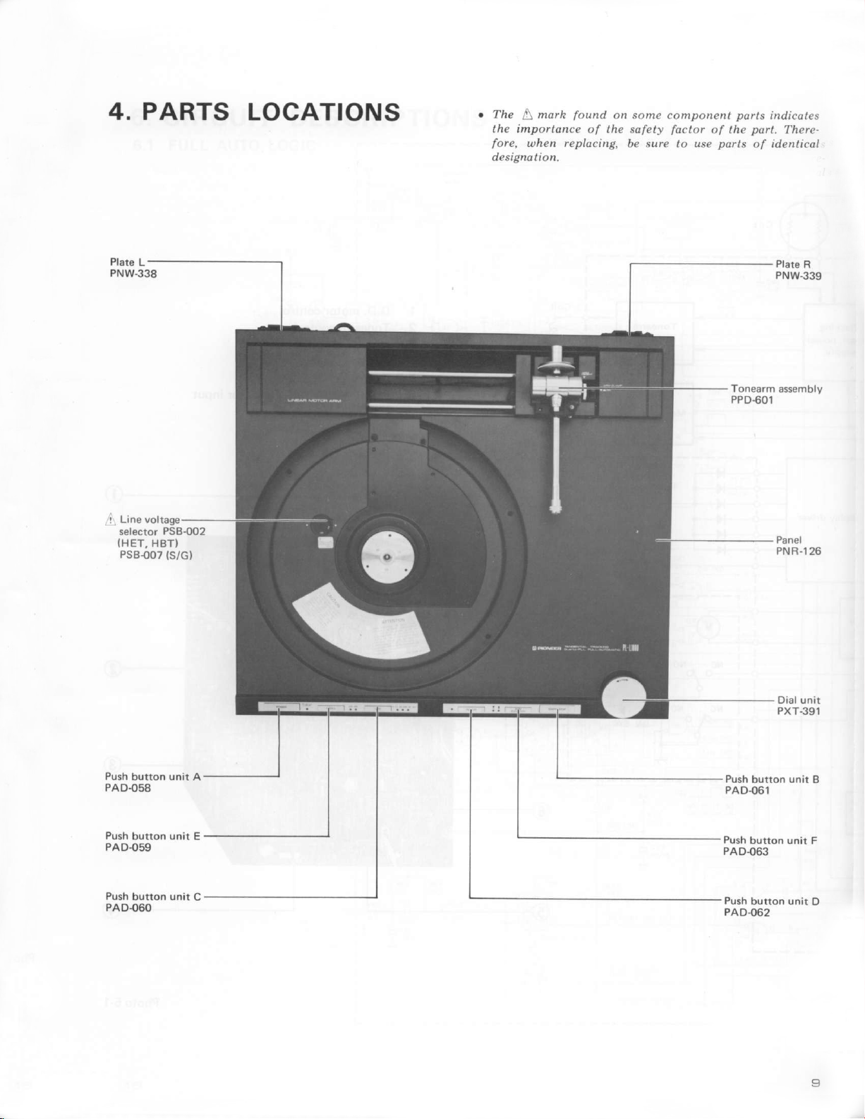
4. PARTS
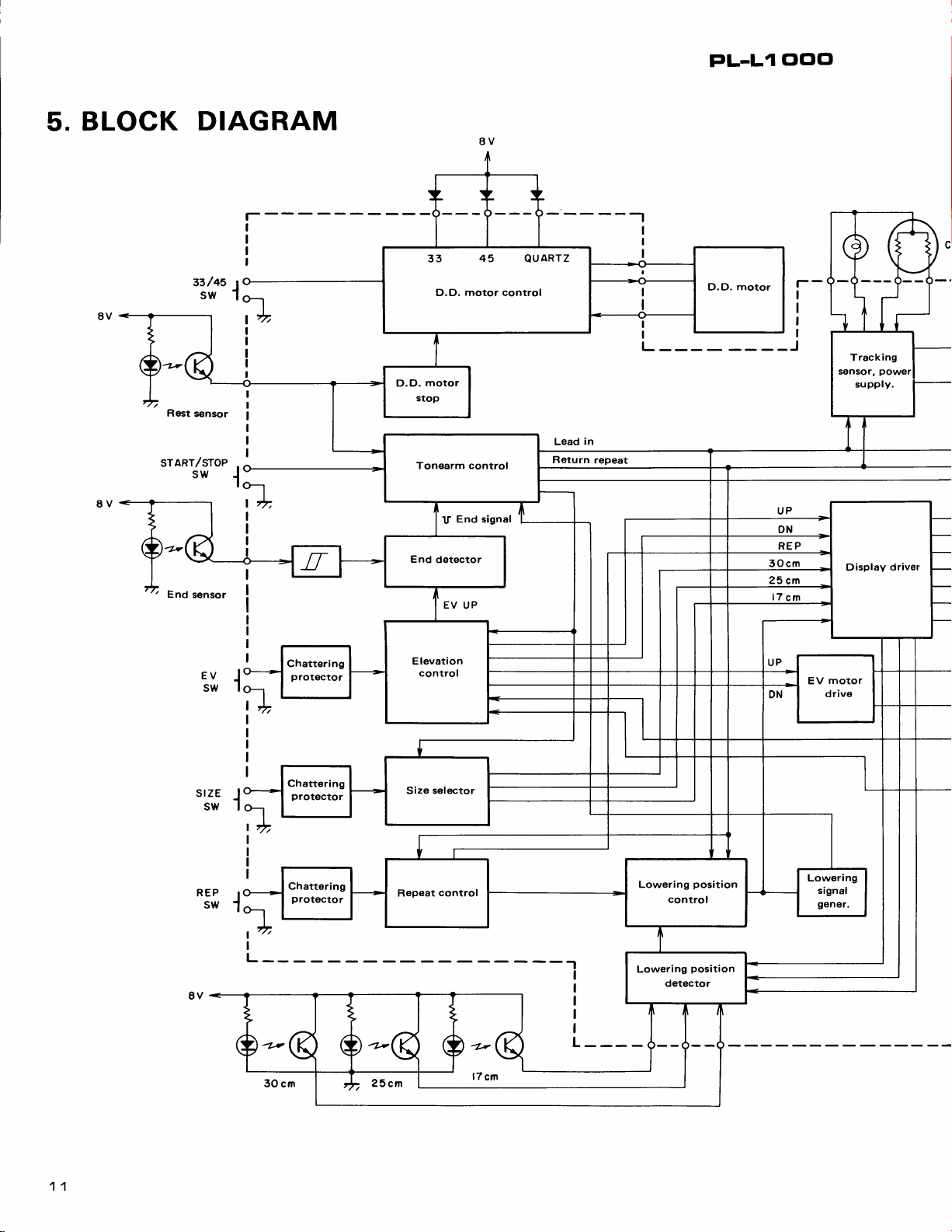
5. BLOCK DIAGRAM
5.1 Tonearm
5.2
5.3
5.4
5.5 Repeat Control
5.6 Lowering
5.7
5.8
5.9 Tracking
5.10
6. CIRCUIT DESCRIPTIONS
6.1
6.2 Tonearm Drive
FACILITIES
Panel
.
CdS Detector
LOCATIONS
Control
End
Detector
Elevation
Arm
Size Selector Stage
Position
Control Stage
Generator
Display
Manual
Tonearm Driver
D.D.
D.D. Motor
Full
Stage
Drive
Sensor
Motor Control
Auto Logic .
Lamp
and
Stage
Stage
Control
Stage
and Descent
Plunger
and
Stage
Stage
Stage
Control
Stop
.
.
.
Detector,
and
Stage
Voltage
(Switchablel
(Switchablel
22OV,24OV and
.
Stage
Plunger
Signal
Driver .
and
(Switchablel
3
4
6
7
7
I
I
11
13
13
13
13
13
13
13
14
14
14
15
21
Europe
United
Military model
U.S.
7. ADJUSTMENTS
7.1 D.D.
7.2
7.3 End
7.4
7.5 Tracking
7.6
7.7 Lead-in
TIMING
8.
TROUBLESHOOTING
9.
9.1 Circuit Block .
9.2 Mechanism Block .
10. EXPLODED
10.1
10.2
10.3
10.4 Bottom
11.PACK|NG....
12.
SCHEMATTC DTAGRAM
P.C.
13.
(HET,
PARTS
14.
(HET,
15.
SCHEMATIC DIAGRAM
16. P.C.
(S/G
17. PARTS
(S/G
(without
model
Kingdom
Adjustment
Auto Lead-in Timing Adjustment
End
Adjustment
Tracking
Exterior
Tonearm
EV
BOARD CONNECTION
BOARD
model)
model)
model
(with
Motor Operating
Sensor Sensitivity
Timer
Adjustment
Sensor
Sensor
Return
and
CHART
VIEWS
Mechanism
Plate
HBT model)
LIST
HBT model)
OF
CONNECTION DIAGRAM
LIST
OF
Remarks
cartridge)
(without
.
P.C.
P.C.
cartridgel
cartridge)
Point
Adjustment
Point
Zero
Gain Adjustment . . . . .
Adjustment . . .
Speed
(HET,HBT
DIAGRAM
BOARD
BOARD ASSEMBLY
(S/c
ASSEMBLY
model)
modet).
.
25
25
25
25
26
26
26
27
3:
45
48
50
51
54
55
58
61
63
t
l
a
e
\
PL-L1
clclcl
Fr
)
ftr,
1.
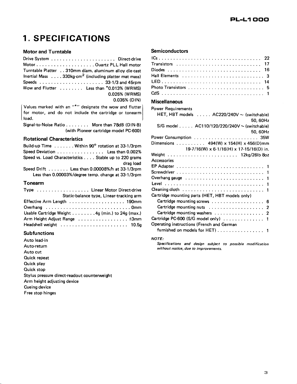
SPECIFICATIONS
Motor and Turntable
DriveSystem
Motor.
Turntable
Inertial
Speeds
Wow
Values marked
for
load.
Signal-to-Noise
Rotational
Build-up Time
Speed
Speed
Speed
Platter
Mass
Flutter
and
motor, and do not include
. . 31Omm
. . . . 330kg-cm2
with an
Ratio
(with
Characteristics
.
Deviation
vs.
Load Characteristics . . . .
Drift .
Less
than 0.00003%/degree temp. change
.
. .
. Less
....OuartzPLLHall
diam.
aluminum alloy die-cast
(including
Less than
"*"
designate the
the cartridge
More
Pioneer
Within
.
cartridge model
90o rotation at 33-1/3rpm
Stable up to 220
0.00008o/o/h
than
Tonearm
Type .
Static-balance
EffectiveArmLength
Overhang
Cartridge Weight
Usable
Height
Arm
Headshell
Adjust Range
weight
.. LinearMotorDirect-drive
type,
. .
.49
Subfunctions
Auto lead-in
Auto-return
Auto
cut
Ouick
repeat
play
Ouick
Ouick
stop
pressu
us
Styl
height
Arm
Cueing device
Free
stop
re
d i rect-readout counterwei
adjusting device
hinges
.. Direct-drive
motor
platter
mat mass)
.
33-1/3
*0.013%
o.o25Yo
0.035%
wow and
than 78dB
Less
Linear-tracking
(min.)
ght
45rpm
and
(WRMS)
(WRMS)
(DtN)
flutter
tonearm
or
(DlN-B)
PC-600)
than O.OO2TI
grams
drag
33-1/3rpm
at
at 33-1/3rpm
....190mm
....0mm
(max,)
to 249
t3mm
. .
10.5g
load
arm
Semiconductors
fCs...
Transistors
Diodes 16
Hall Elements
LED.
.
PhotoTransistors.
...
cds..
Miscellaneous
j
Power
Requirements
I
HET,
HBT
models . . . AC22O/24OV
S/G model
PowerConsumption
Dimensions
Weight
Accessories
EP
Adapter
Screwdriver
Overhanggauge.
Level .
Cleaningcloth.
Cartridge
Cartridge PC-600
Operating
NOTE:
mounting
Cartridgemountingscrews
Cartridgemountingnuts
Cartridgemountingwashers
instructions
furnished
Specif
without
on models for
ications
natice,
ACl
. .
19-7116(W) x
(S/G
and design
due to improvements.
parts
model
(French
10/
12O/22O/24OY
494(W)
6-1116(Hlx 17-15/16(D) in.
(HET,
HBT models
onty) .
and
HET)
subject
x 154(H) x 456(D)mm
German
to
-
-
12kg/261b fbz
only)
possibte
(switchable)
(switchable)
.......
.......
modif ication
22
17
....3
14
..... 5
1
50,60H2
50,60H2
..35W
1
1
......1
1
1
...6
...2
2
1
1
t
T
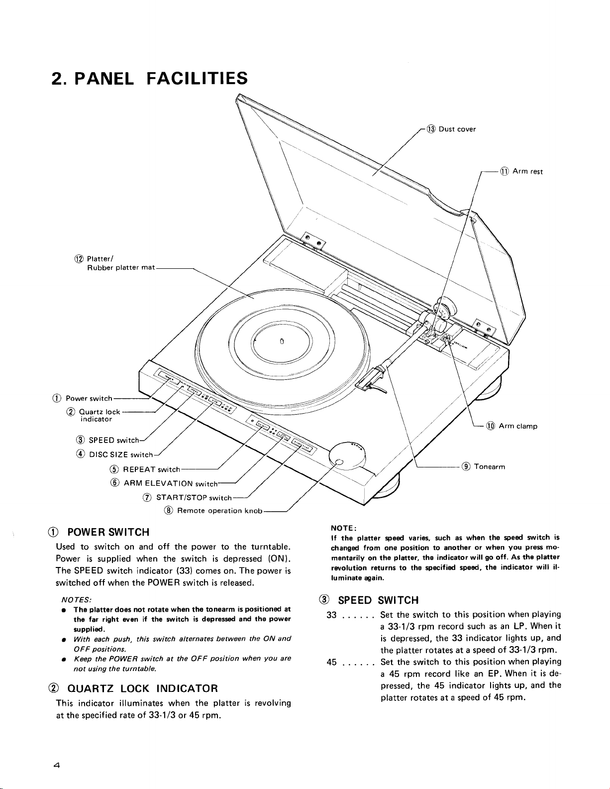
2. PANEL FACILITI
ES
@
Dust
cove.
Arm rest
@
I
a
/t\
Power switch
v
ouartz lock
@
indicator
seeeo
@
otsc slZE switch
@
(!)
R EPEAT switch
(O
ARM
ELEVATION
srnnr/sroP
@
Remote operation
@
POWER
e
Used to
Power
The
SPEED
switched off
SWTTCH
switch on and off the
is supplied when the switch is depressed
indicator
switch
when the
(33)
POWER
switch
NOTES:
platter
r The
the
supplied.
. With each
OFF
Keep the
.
not using the turntable.
euARTz LocK rNDrcAToR
@
doos not rotate
far right oven if the sl,lritch
push,
POWER
this switch
switch
positions.
when
alternates between
at the OFF
This indicator illuminates when the
the specif
at
ied rate of 33-1/3
45 rpm.
or
swi
switch
power
to the turntable.
comes on.
The
is released.
tonearm is
tho
is depressed and
position
platter
knob
(ON).
power
is
positioned
the ON
when
the
powgr
you
at
and
are
is revolving
NOTE:
platter
the
lf
changed
mantarily on
ro/olution
luminate again.
@
33 .
from one
the
returns to the specified
sPEED swrrcH
. . . . . Set
a 33-1/3
is depressed, the
the
45 . . . . . .
Set the switch
a 45
speed varies, such
position
platter,
the
to
ths indicatorwill
switch
rpm record such
platter
pressed,
platter
rotates at a speed
rpm
record
45 indicator
the
rotates at a speed
A-
I onearm
19,
as when the
another
to this
or when
go
sped, the
position
33 indicator
to this
position
like an
of
Arm
ctamp
@
speed s:witch
you press
As the
off.
indicator
when
as an LP.
lights
of 33-1/3
when
EP. When
up,
lights
45 rpm.
is
mo-
platter
will il-
playing
When it
up, and
rpm.
playing
it is de-
the
and
t
r)-
V
a
\.
PL-L1
Clclc'
t
n
n'
t,
I
Drsc
@
Selects the
ord
12"30
10"25
7"17
o
Used
stance,
switch for
the
sets it
o When
will
30cm
you
srzE
swrrcH
switch that
want
.
. . . For
.
to
17cm
to the
always
and the
hear
to
For
. .
30cm
25cm
ForlTcmrecords
. .
select
the record
when
the
the
25cm
position.
30cm
power
the
be
corresponding
set
NOTE:
This
sruitch
will
(auto
moving
REPEAT
@
Press
this switch for
cator
will light up,
(refer
to
Press
this
off and the repeat
not work if
lead-in,
swtrcH
page
12 for further
switch
again
auto-return,
play
NOTE:
This
slitch
will
(auto-return,
moving
enru ELEVATIoN
@
Use this
form
When
descend
arm
switch to
manual
the DOWN
and
rise.
will
ternately every
not
auto
interrupt
play.
position
when the
These
time the
NOTES:
r When
in
r This
moving
o When
nisrn is
sranr/srop
O
Press
this
tate,
the tonearm
edge
of
lf
this
POWER
th€
position.
the UP
switch
will not
(auto
the switch
actuated
switch
the record
switch
lead-in,
is at UP,
and so there
for
auto
will
and
pressed
is
automatically return
ter will stop rotating
cut).
NOTE:
This
moving
saritch
(auto
will
not work if depressed
lead-in).
corresponds
auto
play
operation.
for
records
records
size
when
30cm
indicator
position,
Depressing
and
the switch
position.
switch is
for
turned
records
light
depressed
auto
cut).
play.
repeat
When
and the record
details
release
to
function
work if depressed
cut).
it.
will be released.
swtrcH
play
temporarily
is depressed
position
UP
is
two operations
switch is
switch is
work if depressed
auto-return.
pressed.
set to
ON, the tonearm will
auto cutl.
tho auto-return
will be no
swtrcH
play.
automatically
play
will begin
during
to the
arm clamp
play
and
platter
The
play,
will be
to
the size
of the
depressed. For
lights
up,
depress
depress
it
again
once
ON, the
with
will
come
when
will be
turntable
a diameter
on.
the tonearm
pressed
the indi-
played
on repeat
The indicator
wh6n
the ton€arm is
or
the tonearm
depressed
will
be
when
auto-roturn.
the tone-
performed
th€ tonearm is
cancelling
will start
move
over
(auto
lead-in).
the
tonearm
position,
the
suspended
when the tonearm
rec-
in-
the
for
more
of
again
play).
go
will
per-
to
will
al-
start
mecha-
to ro-
to the
will
plat-
(auto
is
@ REMoTE
Used
Rotate
Rotate
NOTE:
Whon the
cut and
remote
ToNEARM
@
The
force
low
The tonearm
remotely
is
the motor
the
turned to the
NOTE:
When
be
at tho
member
@ ARM
Used
To
secure
down
turntable,
released
anru
@
This secures
rotate
clamp.
switch
and
secure
NOTE:
When
pipe
(
!
pIRIIER/RUBBER
@
When
turntable,
speed.
also
absorbs external
ousr
@
Keep
or changing
cords
straight
cabinet.
opERATtoN
when
moving
counterclockwise
clockwise
auto-return,
operation
to move
arm elevation
the tonearm
is released
tonearm function
to the cartridge.
the
stylus
to trace
can
be
with
the remote
switch
platter
and when
rotates
and it
arm clamp
the POWER
moved
by either
OFF
to
manual
position,
set the POWER
cLAMp
to
secure
the
tonearm.
the
tonearm,
on
the
secure
when
clamp.
the tonearm
the clamp
REsr
the
tonearm
the
arm rest
When
to UP
the
the arm elevation
cannot be
position.
l
the tonearm
the
The
playing
not
(
!
)
pipe.
secured. Make
platter
rubber
and
is moved
platter
vibration,
covER
this closed
during
up,
unless
records.
record
this
dust cover
This
play.
KNoB
the tonearm
to move
the tonearm
switch is
and th6 knob
is
to apply
maintbin
the record
operated
operation
stops
position.
switch
or remote
this
may result
move
When
is raised.
pipe.
counterclockwise
a
then rotate
sritch is
will
start
mat
operating
serves
When fully
the
DOWN
at
does
not move
the correct
this value
grooves
manually
knob.
it moves
when
is
at OFF,
operation.
in damage
switch
to ON when
to
it
the
you
do
not
in
this
way.
When
record,
set
the
at DOWN
sure this
sl,tritch is
pLATTER
power
and
rotating
stabilizes
the controls
keep
to
can
be
by remote
tonearm
to
rotated.
to
right.
the
or auto lead-in,
even
precisely
accurately.
your
with
lt
is coupled
across
to
the record,
the tonearm
the ton€arm
lf it
so
right
and
then
intend
to use
The
tonearm
playing
and
release
the
arm
arm rest
(l
ttre
l,
set to tho UP
clockwise
MAT
is
supplied
at
the
set rotation
the records
or
tonearm,
dust
off
of
opened
removed
and
from
control.
the left.
auto
when
the
tracking
and
al-
hand
or
to
is re-
cannot
forced
is
always re-
moving
it.
push
the
is
a record,
the
elevation
tonearm
to
the
and
the re-
pulled
the
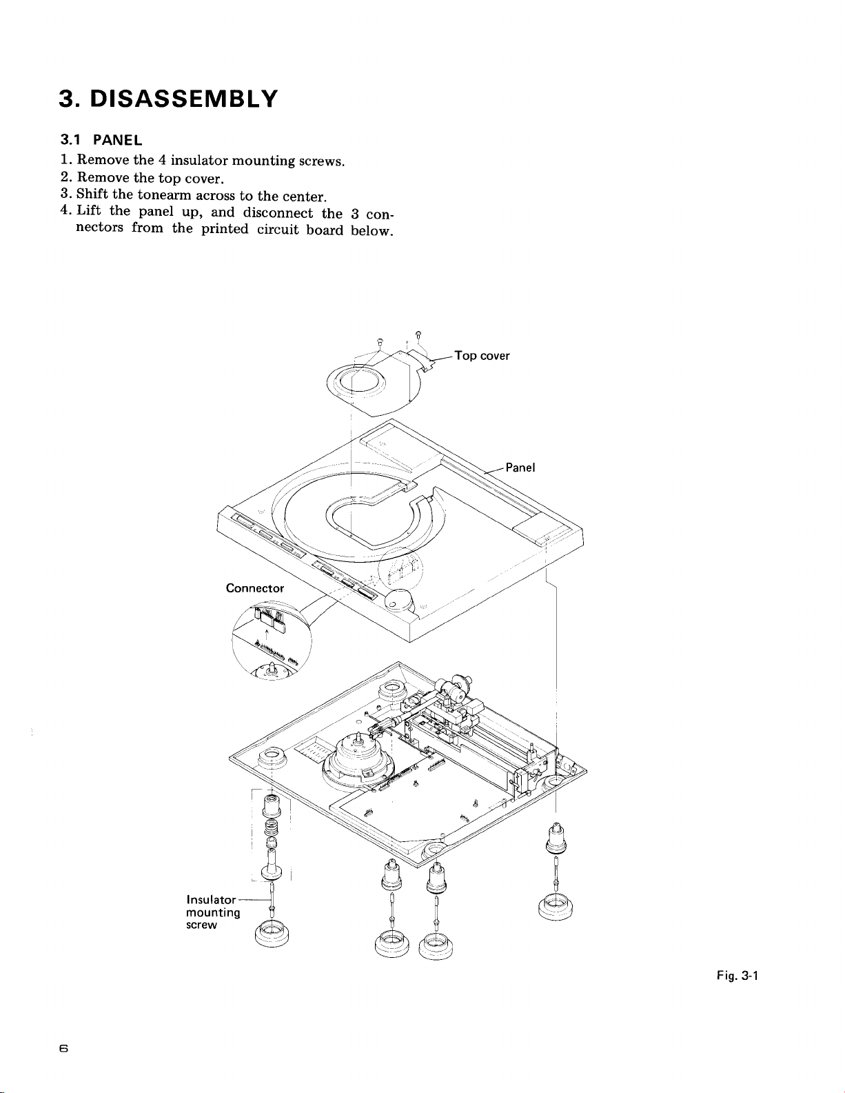
DISASSEMBLY
3.
3.1 PANEL
1.
Remove
2.
Remove
3.
Shift
4.
Lift
nectors
the
the
the 4
insulator
the
top
tonearm
panel
from
the
cover.
across
up,
printed
and
mounting
to the
center-
disconnect
circuit
screws.
the
board
B con_
below.
Top
cover
I
)
a
Fis.
3-1
Ei
FL-LI
Oclcl
t
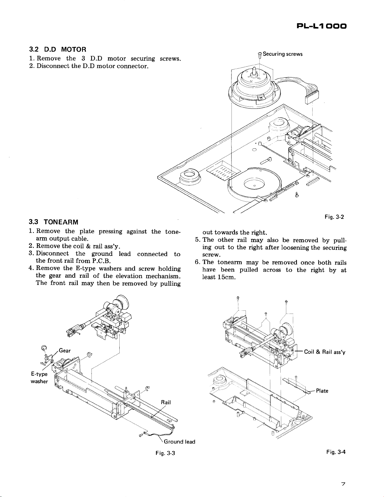
3.2 D.D
1.
Remove the 3 D.D motor
2. Disconnect
)
MOTOR
the D.D
securing screws.
motor connector.
l"
Fis.
3-2
pull-
by
both rails
by
at
a
3.3
TONEARM
1.
Remove
arm output
2.
Remove
3. Disconnect
the front
4.
Remove the E-type
the
The front
gear
the
cable.
the coil
the
rail from
and
rail
plate
& rail
ground
P.C.B.
rail of
may
pressing
ass'y.
washers
the
elevation
then
be removed
against the
lead
connected
and screw holding
mechanism.
pulling
by
tone-
to
out towards
5.
The other
ing
out to
screw.
6. The
have
least
tonearm
15cm.
the right.
rail
may also
the right after loosening
may be removed
been
pulled
across to
be removed
the securing
once
the right
E
!t
E-type
washer
Ground
Fig.
3-3
lead
Coil & Rail
Fig.3-4
ass'y
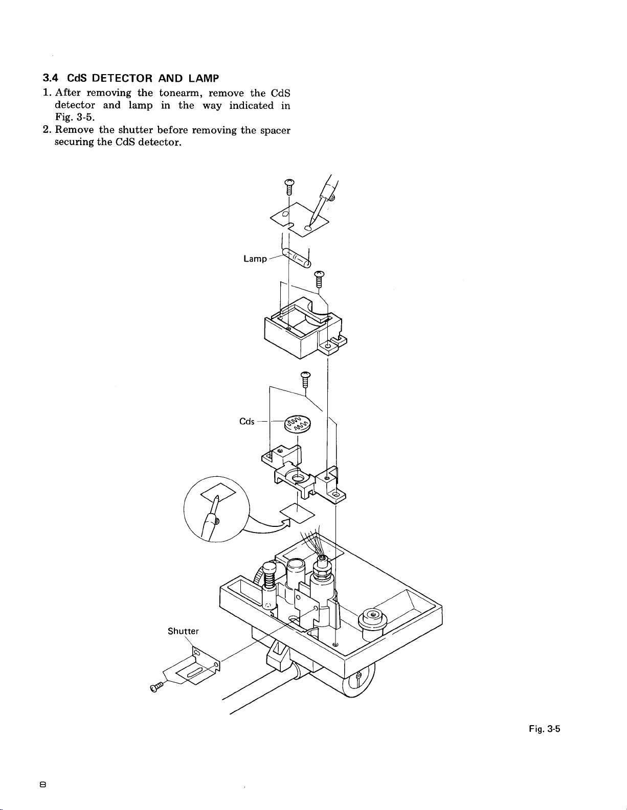
3.4
1.
After removing
detector
Fig.
2. Remove
securing
DETECTOR
CdS
and lamp
3-5.
the shutter
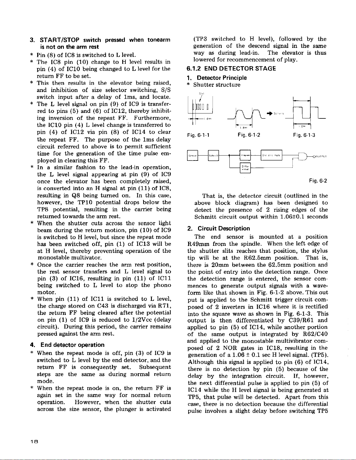
the CdS detector.
AND LAMP
the tonearm, remove
in the
before removing
way indicated
the spacer
the
CdS
in
utter
Sh
\
@
)
I
Fig.
3-5
a
4. PARTS
LOCATIONS
o
The
Ihe importance
fore,
designation.
morh
l\
@hen
otr some component
found
of the sately
replacing,
be sure Io use
lactor
parts
of the
parts
itldicates
parl.
There-
of id.enlical
t
ri
Push
button
PAD-058
unir
Tonearm
PPD€01
A
Push
PAD-061
assembly
PNR.I26
Dial unit
PXT.391
button
unit
B
Push button unit
PAD{60
C
al
tcotes
lhere
'ntlcal
BtE R
rw-339
PL-LI Clclc'
nel
\tR.l26
ialunit
xT-391
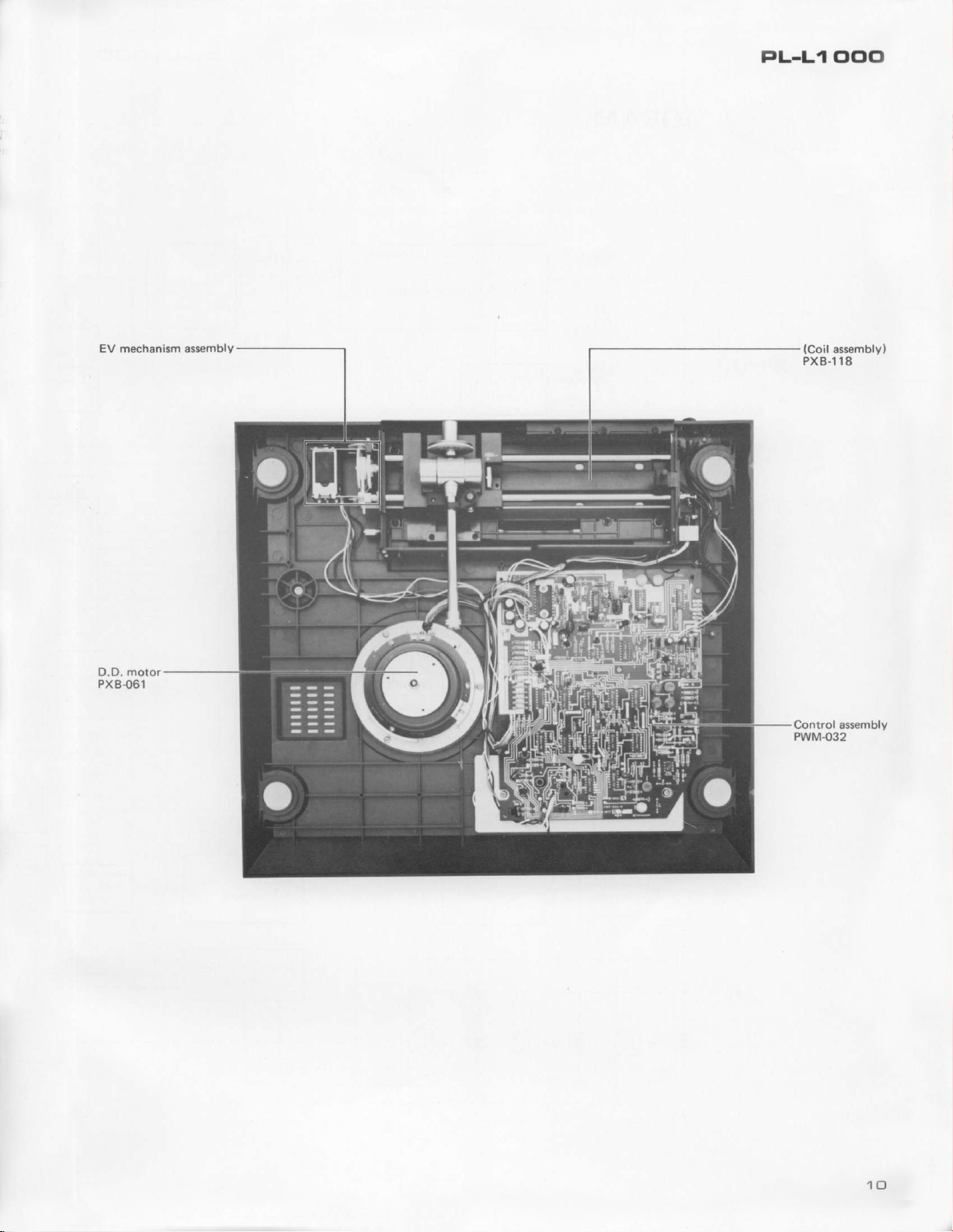
EV mechanism assembly
motor
D.D.
PX
B-061
(Coil
assembly)
PXB{ 18
Controlassembly
PWM{32
PL-L1
oclcl
BLOCK
5.
DIAGRAM
Rest sensor
33
D.D. motor
End signal
|If
45
QUARTZ
control
Lead
-l
I
I
I
in
driver
Display
End
sensor
REP
sw
1q
177
I
L-_
____l
Lowering
I
position
control
11
30
cm
rooo
I
,lr-
Ji
Cds
?
$-€
rl f;
Tracking
power
sensor,
supPlY.
Tonearm
drive
Manual
drive
I
I
I
uoll
I
l<
l'
I
I
I
I
i€
D.D. motor
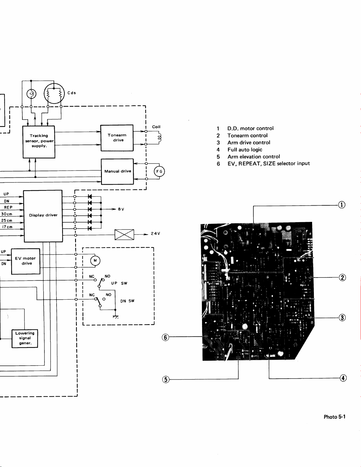
1
Tonearm
2
Arm
3
Full
4
Arm
5
EV, REPEAT, SIZE
6
control
drive control
logic
auto
elevation control
control
selector
input
Photo
5-1
I
BLOCK
5.1
a.
DIAGRAM
TONEARM
Lead-in
Lead-in
Return
b. When
"AUTO
either
AUTO
set
to
the
drive.
5.2
applied
ferential
stable
END
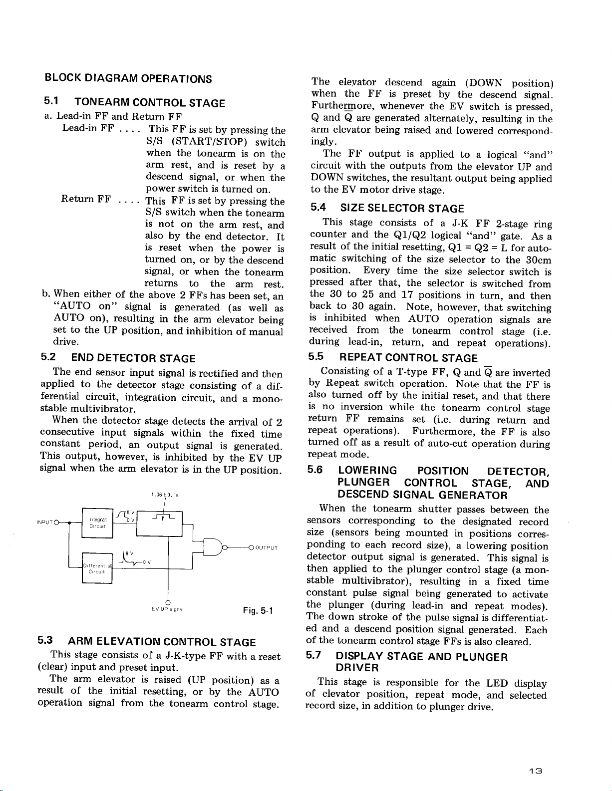
The
end
to
circuit,
multivibrator.
When
the
consecutive
constant
This
signal
5.3
This
(clear)
The
result
operation
period,
output,
when
ARM
stage
input
arm
of
the initial
signal
OPERATIONS
CONTROL
FF
and
Return
FF
.
. . . This
FF
. .
. .
of
the
on"
signal
on),
resulting
position,
UP
DETECTOR
sensor
the
input
detector
integration
detector
input
signals
an
however,
the
arm
elevator
ELEVATION
consists
preset
and
elevator
is raised (Up position)
from
FF
FF
(START/STOP)
S/S
when
arm
the
rest,
descend
power
This
S/S
is not
also
is
turned
signal,
switch
FF
switch
by
reset
or
on
the
on,
returns
above
2
generated
is
in
the
and
inhibition
STAGE
signal
stage
circuit,
stage
detects
within
output
is
signal
inhibited
is in
qna
EV
up s
CONTROL
of
a J-K-type
input.
resetting,
the
tonearm
STAGE
is set
pressing
by
tonearm
and
is reset
signal,
is
when
when
to
FFs
is
set
by
when
the
end
or
by
the
has
or
turned
pressing
the
arm
detector.
the
the descend
the
been
(as
arm
elevator
is
rectified
consisting
and
the
arrival
the
fixed
is
by
the
the
Up
STAGE
FF
with a reset
or
by
the
control
the
switch
is on
the
by
when
the
on.
the
tonearm
rest,
and
It
power
is
tonearm
arm
rest.
ser,
an
well
as
being
of
manual
and
then
of
a dif-
a
mono-
of
2
time
generated.
EV
Up
position.
OUTPUI
Fig.
5_1
as a
AUTO
stage.
The
when
Furthermore,
Q
arm
ingly.
a
circuit
DOWN
to the EV
s.iA
counter
result
matic
position.
pressed
the
back
is inhibited
received
during
5.5
Consisting
by
also
is no
return
repeat
turned
repeat
5.6
When
sensors
size
ponding
detector
then
stable
constant pulse
the
The
ed
of the
5.7
This
of
record
eleyator
the FF
descend
preset
is
whenever
and
Q
elevator
The FF
with
SIZE
This
of
switching
30
to
generated
are
being
output
the
switches,
motor
SELECTOR
stage
and
consists
the
the initial
Every
after
that,
to
25 and
30
again.
outputs
the
drive
QUQ2
resetting,
of the
time
17
when
from
lead-in,
REPEAT
Repeat
turned
inversion
FF
the
return,
CONTROL
of
a
T-type
switch
off
by the
while
remains
operation.
operations).
off
as
a result
mode.
LOWERING
PLUNGER
DESCEND
SIGNAL
the tonearm
corresponding
(sensors
applied
being
to each
output
to the
record
signal
multivibrator),
signal
plunger
down
and
tonearm
DISPLAY
(during
stroke
of
a descend position
control
STAGE
DRIVER
stage
is responsible
elevator position,
size,
in
addition
again
by
the
the
EV
alternately,
raised
and
is
applied
from
resultant
lowered
the elevator
output
stage.
STAGE
of
a J-K
logical
Ql
size
selector
the
size
the
selector
positions
Note,
AUTO
however,
operation
tonearm
and
repeat
STAGE
FF,
e
Note
initial
the
set
reset,
tonearm
(i.e.
Furthermore.
of
auto-cut
POSITION
CONTROL
GENERATOR
shutter passes
to the
mounted
is
plunger
in
size),
a lowering position
generated.
control stage
resulting
being
lead-in
the
generated
pulse
and
signal
signal
stage
FFs
AND
PLUNGER
for
repeat
to
mode,
plunger
(DOWN
descend
switch
is
resulting
correspond-
to
a logical
being
FF
2-stage ring
,,and,'
=
Q2
gate.
=
L
to the
selector
is
switched
in turn,
that
signals
control
stage
operations).
and
are inverted
Q
that
the FF
and
that
control
during
return
the FF
operation
DETECTOR,
STAGE,
between
designated
positions
This
in
a fixed time
to
repeat
is differentiat-
generated.
is
also
cleared.
the
LED display
and selected
drive.
position)
signal.
pressed,
in the
,,and"
Up
and
applied
As a
for
auto-
B0cm
switch
from
and
then
switching
are
(i.e.
is
there
stage
and
is
also
during
AND
the
record
corres-
signal
is
(a
mon-
activate
modes).
Each
is
5.8
By
motol
sensol
f,onea.
opera
is DC
return
5.9
Thr
CdS
voltag
ment.
the
d
par
to
the
to
EITOT
sensor
./.
7
V
\
r
PL-L1 000
5.8
motor
sensor
tonearm
operation
is
retum,
5.9
MANUAL
By
amplifying
mounted
stage
to
is inhibited,
DOWN
during
and repeat).
TRACKING
TONEARM
The
tracking
CdS element,
voltage
ment.
the
to
the
elror
sensor
differences
These output signals are then
driver
pass
tonearm
stage
a current
(i.e.
to avoid
in
outputs).
DRIVE
the
in
balance
be
moved
auto
SENSOR
DRIVER
sensor
and
where
through
such
STAGE
input
the
to
locate
power generator
the
stage,
the
tracking
is upset, permitting
back
and
forth.
however,
operation
when
modes
STAGE
the elevator
(lead-in,
AND
STAGE
(consisting
stage
shutter)
generates
of lamp,
*
in response to tonearm
applied to
they
are
amplified,
a way
the
the drive
as to eliminate
generation
coil
of
to drive
tracking
tracking
the
Such
and
move-
and
5.10
The
motor
MOTOR CONTROL
D.D.
MOTOR
D.D.
phono
when
motor stop control stage stops the
the rest sensor detects
STOP CONTROL
of the tonearm back on
the tonearm
will continue to
stage
employs 3 specially designed
PA2OA4,
remains
off
rotate. The
PD1003. These control stages also
and
the
the arm rest, the motor
STAGE AND
rest.
arm
phono
motor control
ICs - PA2005,
the
As
presence
long as
include the speed selector, speed indicator, and
qtartz
lock indicator circuits.
-
End
detector
Lowering
detector
positioi
Rest
sensor
Fis.
5-2
PL-L1
c,Clc'
€i.
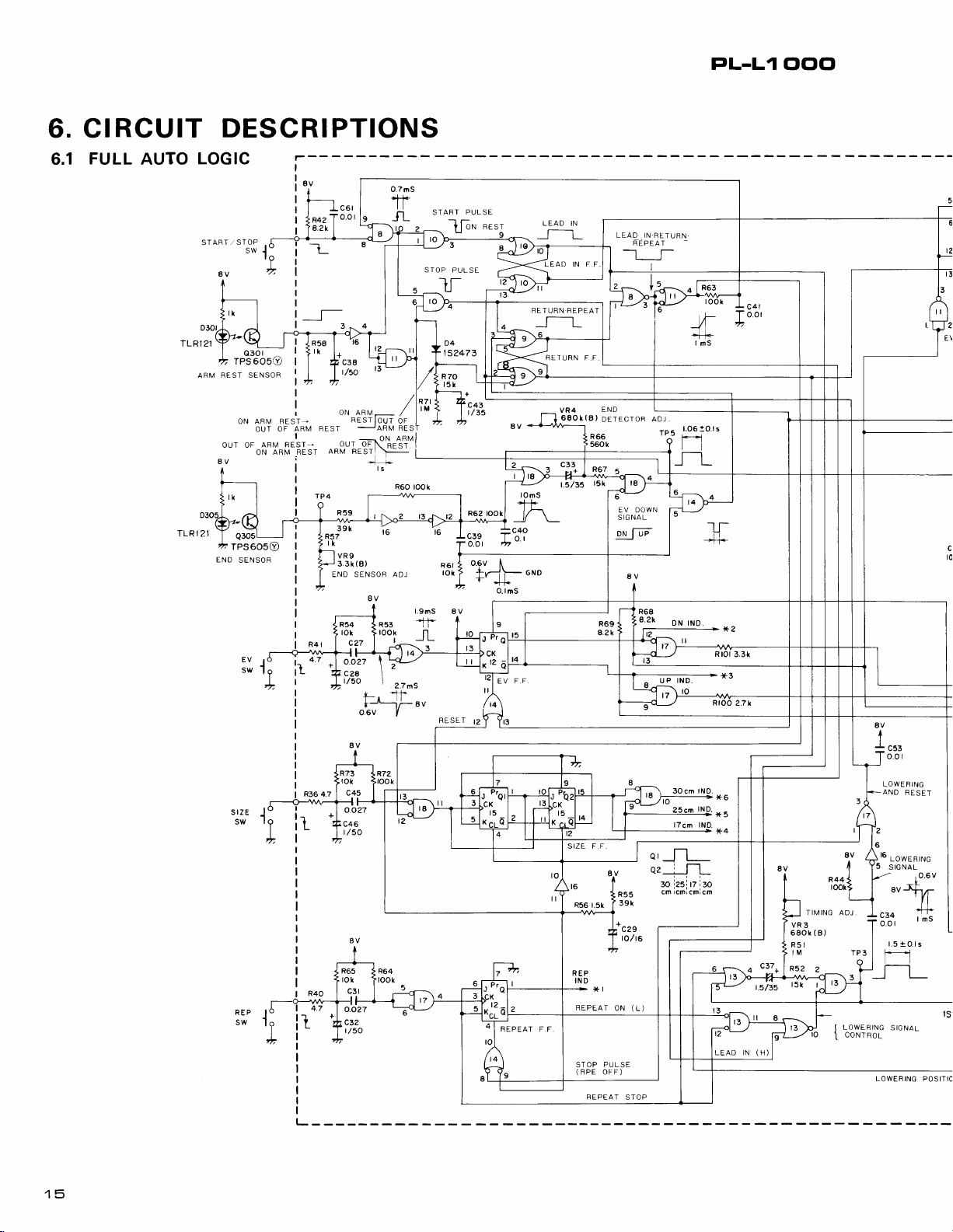
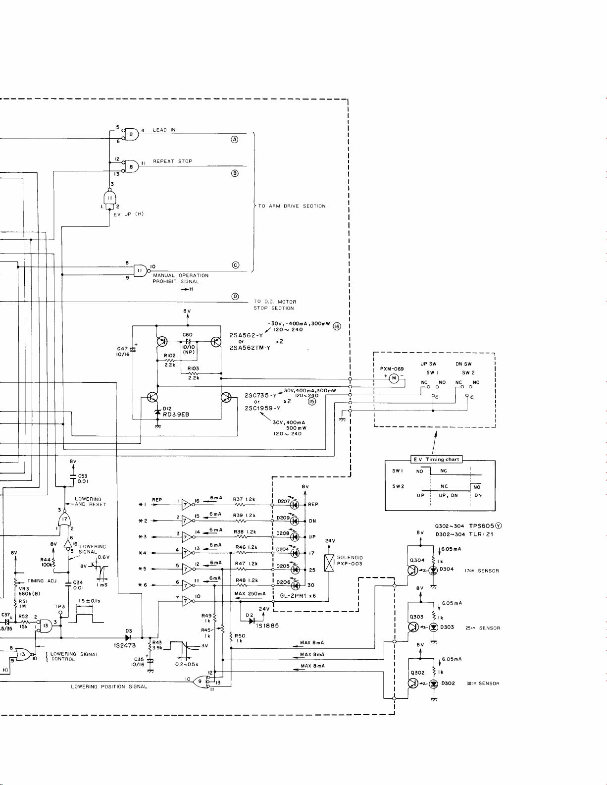
CIRCUIT
FULL
6.1
AUTO
DESCRIPTIONS
LOGIC
O.7nS
-rt
g
fL
|
o30
TPS60S0
REST SENSOF
ARM
8V
END
r
ON
OUT
Q3O5L--
t
TPS6050
SENSOF
AFM RESTOUT
ARM REST-,
OF
ON
I
ARM
OF
I
ARM REST
c38
t/5o
oN ARM-
RESTIoUT
JARM
REST
orr
*xot.tltl
aRv nEStl
-t
R59
,urtt'
rk
VR9
3.3k(8)
END SENSOF ADJ
8V
R54
rok
c27
ocizz \ y-,
c?a
t/5o
l#
fr__..iFuu
o.6v
rok
c45
o.o?7
c46
t/50
8V
R65
tok
-lt-
7
o.o2'
ic3?
t/50
r3
/lazt
/
l'u
oF
I
REST
!
ts
R60
took
io
\
I
e.zrs
I
STAFTJULSE
Lolr
STOP
PULSE
*es-t
Ir
lK.liJ_-r\_
c3s
+i"9
'
-
,,
o.ol
o.gv
I
fy--j l-
-r
oruo
'l+
O.lnS
REPEAT F.F
RETURN
VR4
680I(B)
t.S/3S
16
q55
REPEAT
F.F.
END
DETECTOF
R66
560k
t5k
BV
1.51
LEAD
--t__f-
|
{nss
ssr
|
ON
IN.FETURN
REPEAT
ADJ
TP5
a._fl-L
.o
cmicm cmicm
(L)
.
jasl
rz
iro
R rOl
3.3k
LEAD IN
(H)
TII\,4ING ADJ
VR3
680k
R5l
IM
R52
(B)
?
rL0wERrNG
I
8V
:J---r_
CONTR0L
A
I
I
o.o
LOWERING
AND
FESET
16
r-owEntruc
IG NAL
S
:"t
r 's
3:"1
1.5!Ols
fi
StcNAL
BEPEAT
STOP
1
clclcl
t
I
IN
LEAD
REPEAT
ST0P
ra)
@
TO AFM
DRIVE SECTION
rc
I
g1_-_/
bl J
to
L.owERlNc
coNTROr
1
8V
I
I
I
o.o
LOWEF
ING
AND
FESET
16
loweRtnc
5
srcNAL
:"t
r 's
3.t"t,
+
1.5
O.l s
fi
'_r-L_
srcNAL
LOWERING
c47
to/t6
,o.r1?
POSITION SIGNA.
l(l
x?
.t€
*4
.n5
,(6
MANUAL
PROHIBIT
3
+
i
OPERATION
SIGNAL
+H
.^
15
r+
,u
ra
rr
-tga
-9i1A
6mA
6mA
tto
6mA
o
6)
TO
D.D.
STOP
SECTION
-3ov,-4ooma,3oomw
y' tzoN
-Y
2S 456
2
or x?
A562 TM-Y
2S
-Y-
25c735
orx?(9
-Y
25C1959
\
3OV,4OOmA
l?Q
I
r.2k
t.zl
D?
lsr885
I
I
I
I
R37 t.2k
R39
R38 r.2k
R46 r.2k
R47
MAx.25Oma
MOTOR
24o
3OV,4OO
-
5OOmW
* 24O
0209
ol_zeRt
mA,3OO mw
tzo-zAo
REP
DN
UP
t7
?5
30
,e
MAX
8mA
MAX
MAx
8mA
8mA
r;\
\9
l.
SOLE
PXP-OO3
PXM-069
UP
ON
SW
swt swz
SW
NC NO NC NO
I
I
l1
rl
L---
_____J
swl
sw2
-30a
NO
ID
-- --]
r
Q303
Q3O2
8V
8V
<L
+4.
Q302
D3O2-3Oa
t
tk
1
tk
t
tk
16.05
0304
6.05 ma
D3O3
6.O5mA
|
0302
rPS60so
TLRI
nA
lTcm
25cm SENSOB
30cn SENSOR
21
SENSOR
*
Number
x
LdenotesLlevel.
*
HdenotesHlevel-
*
EV
denotes
elevator
elevator
The
Full
following
Tonearm
(1)
End
(2)
Elevation
(3)
(4) Record size selector
(5)
Repeat control
6.1.1 TONEARM
1.
When the
. . .
. the
by
C29lF-55 to IC16,-+ICI7,->IC9,
. . . . the
if the
commence
moved
2. When
with
*
*
*
*
(8)
Pin
(10)
Pin
appears
lead-in
being
switched
Once
pin
(3)
pin
in
L level,
operation).
(13)
Pin
resulting
H level,
raised
(
Pin
ing in
STOP
(in
order
set
when the
the
same
H
level
Hence,
elevator
ing
inhibited.
parenthesis
in
arm
elevator,
is in
is
in the
Auto
5 main
detector
lead-in
the initial reset
phono
the
the
tonearm
of IC8
of
at
FF
pin
(10)
of IC8
(8)
thereby inhibiting
of IC14
in
and the
to the
of IC11
)
the inhibition
switch
to
time,
to inhibit
the relevant
raised,
UP
DOWN
Logic section
stages.
control
control
power
START/STOP
IC8 is
pin
being set
of
pin
UP
stage
stage
stage
stage
CONTROL
switch
FF
motor
tonearm is
rotate
to
away.
on
is
switched
switched
(3)
to H level).
of
IC10
is switched
IC1L
is
(12)
elevator
position.
is switched
inputs
prevent
tonearm leaves
pin (12)
switching
and record
are
the IC
UP denotes
position,
position.
stage
STAGE
is
turned
and retum FF
signal
will remain
on the arm rest,
if it has
switch is
the arm
to L level.
to H level,
of
IC10,
(and
pin (10)
is switched
to L level,
being likewise
manual
also switched
of IC12
being
of
any further
after a delay
the return FF from
of
IC18 is
of
FFs
size
pin
while DN
is
made up
on
. . .
are
(passed
and
stationary
alreadv been
then
rest,
resulting
of
IC10
to H level,
switched
drive
to L level,
being switched
consequently
to H level,
of about lms
the
arm rest).
switched
the size selector.
are set,
selector switch-
numbers.
that
arm
that
of the
.
reset
from
IC10).
but
pressed
and
this
in
the
also
resulting
to
(locate
to
result-
START/
being
At
to
the arm
(11-)
Pin
transferred
properly
is
switch is switched
pin
in
pin (4)
This IC8
resulting
VRb and R99 via
drops
ference
through
czrlrier.
The
the record.
When
in front
will
Pin
and
serves
brator incorporated
generation
This is
presetting
arm.
The
in
turn attracts
plate.
The carrier
ing
index
TP3
later,
and R44
which is
clear
The
selector
at the
As
a further
level,
R43 and
discharge
is
maintained
forced
has
retumed
of IC10
to
in the
(5)
of IC8
of IC8
pin
in
a current being
below
is
the
carrier is
the carrier reaches
of the
block the light
(13)
of IC9 is
pin
(10)
as a trigger for
of an H level
applied to
the
TPB H
to a stop
is switched
the
elevator
been
level signal
plate.
the signal being
provide
to
passed
FFs
switching
same time.
the charge
the IC7
period
back
eompleted.
to DOWN
is switched
pin (6)
UP
to the NO
being
switched
(4)
H level
R93.
potential
the
amplified
coil to subsequently
thus shifted
(Assume
30cm
of
of IC9 switched
EV
FF for
the
continues
when the swing
back
via
and
stop the
UP, locate
inhibition
result
held
base resistance.
(0.3
in
the attracted
(by
a spring)
position
PL-L1 clc'cl
to L, and
of ICS.
position,
switched to L level,
to H level.
signal
size selector
position,
the 30cm sensor.
thereby
the monostable
in IC13,
TP3
is used
plunger
to L level
the tonearm
IC1-7, IC9
of TPB
by
to
The elevator
Once the elevator
the UP detector
position,
then turns
passed
If
and a current
a
to move further,
differentiated
potential
the
at TP10,
across towards
set to
position
the carrier
switched to L level,
to H level.
resulting
signal
and
C35
0.5 sec.)
of r = 2.2 sec.
pin
lowering
to drive IC7,
raise
and
pin
descend
and IC10
carrier drive
inhibition,
are dlso cancelled
being
switched
is
discharged via
position,
once
the discharge
for
start of
this is
resulting
and
on,
Q7
from
VR8 to
at TP8
the dif-
passed
drive the
30cm).
about
(9)
20mm
shutter
This
multivi-
in the
of lCL2,
of
the tone-
and
index
the
com-
strikes
2.2 seconds
During
the
is thereby
by
C34
signal
current.
and
to
plunger
but is
play.
the
size
this
to
L
l
3. START/STOP
is not
on
x
(8)
Pin
*
The IC8
pin (4)
retum FF to be set.
*
This then
and inhibition of size selector switching, S/S
switch input after a delay
*
The L level
red
ing inversion of the repeat
the
pin (4)
the repeat FF. The
circuit referred to above
time
ployed
*
In a similar fashion to the lead-in operation,
the L
once the elevator has been completely
is converted into an H
resulting in
however, the TP10
TP8
retumed towards the arm rest.
x
When the shutter
beam during the
is switched to H level, but since the
has been switched off,
at H level,
monostable multivator.
t
Once the carrier reaches the arm
the rest sensor transfers
pin (3)
being switched to L
motor.
+
When
the charge stored on C43
the return
on
circuit). During this
pressed
4. End detector
*
When
switched to L level by the end detector, and the
retum FF
steps are the same as during normal
mode.
*
When the repeat mode is on, the retum
again
operation. However, when the shutter
across the size sensor, the
of IC8 is switched
pin (10)
of IC10 being
pins (5)
to
pin (4)
IC10
of IC12 via
for
the
in clearing this FF.
level
potential,
of IC16, resulting in
pin (11)
(1)
pin
against the
the
set in the same way for normal return
switch
the arm rest
results in the elevator being raised,
signal on
and
L level change is transferred to
generation
signal appearing at
being turned on. In this case,
Q8
resulting in the
retum
thereby
of IC11 is switched to L
FF
being cleared after
of IC9 is reduced to 1/2Vcc
operation
repeat mode is
is consequently set. Subsequent
pressed
to L level.
change to H
changed to L
pin (9)
(6)
of 1C72, thereby
pin (8)
purpose
is
of
signal
potential
cuts
across
motion,
pin (1)
preventing
and L level signal to
level to stop the
is discharged via R71,
period,
arm rest.
when tonearm
level results in
level for the
of 1ms, and locate.
of IC9 is transfer-
inhibit-
FF.
Furthermore,
of IC14 to clear
of the 1ms delay
permit
to
the time
pin
at
drops below the
the sensor
operation
pin (11)
the cauier
pin
off,
plunger
sufficient
pulse
(9)
pin
(11)
carrier being
pin (10)
repeat mode
of IC13 will be
position,
rest
of
potential
the
remains
(3)
of IC9 is
is activated
em-
of IC9
raised,
of IC8,
light
of IC9
of the
IC11
phono
level,
(delay
return
FF is
cuts
(TP3
generation
way as during
lowered for recommencement
6.1.2 END DETECTOR
1.
*
Shutter structure
hhnin n
ff"" " I
.IE;
switched to
of the descend signal in the same
Detector Principle
-r\4'
i
Fis.6-1-1
That is, the detector
above block
detect the
Schmitt
2, Circuit Description
The end sensor is mounted at a
R49mm
the shutter
tip will be at the R62.5mm
there is 20mm between
point
the
the detection range is entered, the
mences to
like
form
put
is applied to
posed
into the
output is then differentiated
applied to
of the same output is
and applied to
posed
generation
Although this signal is applied
there is no
delay
the next
IC14 while
TP5,
case,
pulse
of 2 inverters
of 2 NOR
by the integration circuit. If, however,
that
there is no detection because the differential
involves a slight delay before switching TP5
presence
circuit output
from the spindle.
slits reaches that
of entry
generate
shown in
that
square wave as shown in
pin (5)
the monostable
of a 1.06 1 0.1 sec
detection by
differential
the H level signal is being
pulse
H level), followed
lead-in.
The elevator is thus
play.
of
STAGE
-l-Ll-
#E
Fig.
6-1-2 Fis.6-1-3
circuit
diagram) has been designed to
of 2 rising edges
within 1.0610.1 seconds
the
into
output signals with a wave-
the Schmitt trigger
of
gates
will be detected. Apart
detection range. Once
the
Fig.
in IC16
IC14, while
integrated by
in IC18,
pin (5)
pulse
is applied to
(outlined
When the
position,
position.
62.5mm
above. This out
6-1-2
where it is rectified
Fig.
by
C39/R61
another
multivibrator com-
resulting in the
H level
pin
to
because of the
by the
[1
Fis.
6-2
in the
of
the
position
left edge of
the stylus
That is,
position
sensor com-
clcuit com-
6-1-3.
signal.
(6)
pin (5)
generated
and
This
and
portion
R62|C4O
(TPb).
IC14,
of
from
this
.Jl
q
of
at
FL-L1
clclcl
to H level.
Furthermore,
nected
-position),
ed,
also
hibiting
6.1.3
x
*
x
x
x
*
lit
x
The
x
to
tion
*
*
may
and
to
thereby
when
ELEVATION
When
reset
sigrral
R551C29,
(14)
of IC12
This
corresponds
position,
UP
given
when
Since
be
turned
Until
UP
detector
resulting
both
switched
the
elevator
to start
Once
the
the
UP detector
position,
switched
switched
turned
If
the
edge
differential
(1)
and
pulse
=
H
Q
(DN).
And
since
up,
DN
position
period,
this
both
at
at
H level.
will
Q15
If
the
condition,
reverse
The
of
automatic
tonearm
DN
at the lowering
be
clear
when
pin
(6)
of
the monostable
inhibiting
power
the
the
multivibrator.
CONTROL
power
the
resulting
the
=
Q
on
the
elevator
in
up
the motor.
elevator
resulting
to H
to
off
and
elevator
(2)
pin
on
and
Q
and
the
detector
until
L level,
thus
elevator
Q
the
above
the
control
controlled
terminals.
switch
passed
is
being
or in
power
H,
one
to light
switch
pins
(13)
to L level,
drive
is
switch
level,
L level.
the
switch
of
lCL4,
(13)
=
L for
Q
=
H,
the DN
UP indicator
the
elevator
pins
(9)
while
The
elevator
be
switch
will
switch
motor.
description
elevator
mode
the elevator
IC18
to
multivibrator
the
detector
switch
is turned
pin (12)
to
pin
in
switched
to
the
elevator
other
reaches
stage
in
motor
pulse
switch
on
UP
stage),
via
words,
is
first
of the
up
the
remains
and
being
properly
is
pin
pin
and
Q1B
stopped.
is
then
is
and
of IC12.
lowering
indicator
is right
and
pin
and
is
to
relates
circuit
(as
and
position,
the
FF
make
Q
circuit.
is
tumed
STAGE
on,
of IC14
(11)
of IC14
to H
level (Q
being
Up
turned
ICZ
transistors
Up
indicator
the
in
(I2)
and
in
switched
(18)
(11)
and
generated
a rising
turned
remains
(8)
(10)
drive
the
pressed
L and
itself.
described
elevator FF
position
Up
the
NC
of IC1Z
e13
both
the
Up
of
of
e16
pressed,
This
of
the
lamp
off.
down.
of
IC1T
of IC1?
stage
motor
Q
to the
In
Q
=
H
is
inhibit_
on,
again
an
and
priority
on.
position,
and
e16
turned
position,
to
the NO
IC1?
IC1Z
are
a falling
on
edge
results
elevator
will
in
the
During
will
will
e14
rotating.
during
to
H
addition,
under
is
con-
(i.e.
Up
=
Q
in-
initial
from
pin
=
H).
in
the
will
lamp.
the
being
of
on
being
being
both
pins
clock
in
be
NC
be
be
and
this
(Up)
opera_
the
preset
H
is
6.1.4
x
*
*
*
6.1.5
*
*
x
x
RECORD
When
signal
switch pin
being
Pin
both
ferred
IC18
indicator
If
'
edge
IC18
(i.e.
modes
(11)
activating
Q1
is
turned
If
indicator
selector
cyclic
When
signal
ICI4,
switched
being
The
off(sinceQ=L).
If
edge
(5)
pulse
repeat
this
both
=
At
to
tivibrator
to
If
= K =
J
x
the
from
cleared.
(1) (Q1)
switched
to
is
thus
the
size
differential pulse
when
when
was
of
IC18
=
H
and
turned
on.
the size
is
order
REPEAT
the
from
resulting
switched
repeat
the
repeat
differential
(6)
and
generated
or return
time, pin
be
at H
L for
the same
L level,
operate
the
In
The
activate
edge pulse
and
(10)
the
Q=LandQ=H.
the
repeat
H
status
addition
START/STOP
then
of
IC12
SIZE
power
pins
lamp
none
operative),
the
off,
selector
lamp
pressed,
power
to H
indicator
thereby
consisting
during
return
applied
IC14
FF
is
P"55lC29
(11)
to
and
to
(8)
switched
is lit
selector
pin
(12)
of the lead-in,
as a rising
ring
=
Q2
and
is
-->
30
25
CONTROL
is
R55/C29
in
level,
to
L level.
switch
pulse
of
lCL7,
at
modes
(5)
(K)
level,
repeat
pin
time,
enabling
repeat.
switch
will
to the
mode.
generated
is
is
thus
cleared (repeat
SELECTOR
turned
H level,
pin
L level,
and
up.
is
counter
L. The
the
is
turned
the
->
turned
pin
and
lamp
is
pin
resulting
indicator
of
is
be inverted.
above
switch
to
on,
passed
is
(15)
this
(9)
of
to
H level
pressed,
then
applied
of
this
is
instead
edge
clock
in IC1b.
BOcm
2bcm
pressed
on.
size
L7.
STAGE
on,
is
applied
(10)
pin
will
then
will
be
and
a rising
(4).
are
(6)
and
in
(13)
of IC13
the monostable
gate
2
pressed
then
repeat
may
In
this case,
on
pin
(S)
switched
STAGE
the
initial
to
IC16
resulting
(e2)
then being
IC18.
to
IC
was
return,
indicator
indicator
again,
Every
is
switched
the
of
this
(1)
thus
pressed,
applied
As long
not
(J)
e
to
be
circuits
control
be
pin
of
to H
off), resulting
in
of rClb
pin
(10)
and
the
the falling
pin
(18)
at
L level
or repeat
applied
pulse,
to
thereby
As
a result,
the
time
intial
pin
(g)
IC
(e)
of.
be
turned
a falling
to
edge
as
operative
of
IC12
-
H,
and
turned
is switched
in IC1B
again,
stage,
pressed
a falling
(4)
of IC10,
ICL
.
level,
reset
IClb
are
transBOcm
pin
to
lamp
lamp
17cm
the
in
reset
of
being
lCL2
pins
clock
the
at
will
Q
on.
mul-
the
to
pin
and
in
to
of
of
a

*
When the
repeat mode),
level, this being
terminals
any inversion.
ing
of the
retum
pin
FF
(9)
is set
(during
IC9 is switched to
of
return or
transferred to the J and
repeat FF,
thereby
inhibit-
L
K
I,
TONEARM
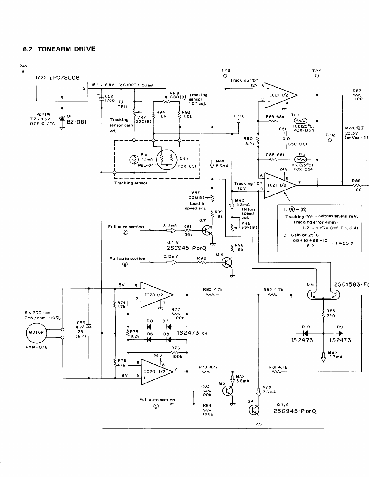
6.2
DRIVE
24V
tczz
Po:lW
-
7.7
8.5V
Q.o1o/o
!PC78LOB
oC
/
15.4
-
16
8V Io SHORT : t
TPII
Tracking
gain
sensor
adi.
Full
Full auto
auto
section
sectaon
50 mA
8V
TOmA
PEL-
04
EEBr',
R93
I
o'13mA
25C945-PorQ
l3mA
o
IJ;:j;"'
"O"
t.?k
Lead
speed adj.
R9l
Rgz
adj.
TP8
Tracking
"O"
t?v
3
TP9
rc?t t/2
R89
RgB
MAX
5.3mA
t?v
"O"
5
rczt t/2
Tracking
in
tl.Bh
o:
TH I
68k
cq,.
, .c50
6Bk
tok
?4v
|
@-@
Tracking
Tracking
Gain of 25oC
?.
68+tO+68+tO
t?!',l33Tl
0.ol
TH
2
(250c)
PCX-
O54
"9" --within
error 4mm
1.2 - 1'.25V
4.2
MAX
22.3V
(otVcc:24
several
-----
(ref.
Fig.
+t=2O.O
€E
mV.
6-4)
5,v 2OO
7mY
rom
/
-
PXM
076
rpm
l9o/o
ltj
D6
TC20 t/2
Full
auto section
24t!
D5
took
152473 xq
R79 47r
R80 4.7k
MAX
3.6 mA
q4
R82 4.7k
ts
R
4.7k
81
MAX
3.6mA
Q4,5
25C945-PorQ
2473
25Cl
15
MAX
2.7 mA
?47 3
583-
Fr
TP
I?
--within
error 4mm
,1'.25V (ref.
several
+
2S Cl583
1S?473
MAX
2.7 mA
MAX
?2.3V
(ot
mV.
--
--Fig.6-4)
t=20.o
roc
€E
Vcc
| | uAx
=
?4Y
I
-
For
G
I
to/35
ceg
3OOmA
(
250
t?5A671-Bor C \
\
esclo6l
t25A816-OorY \-^
\
zS
Cl
-Borc)
c 16?6- o orY
x
)
Coil Ass'y
PXB-II8
R=73t5rl
(or
25('C)
TPlO
@
volt
R
2 or
^'
Fis.
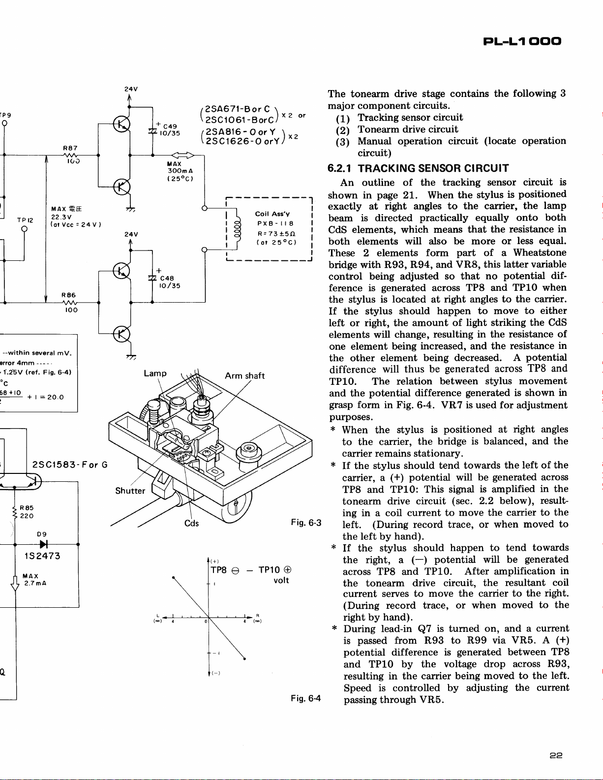
The tonearm
major
component circuits.
Tlacking
(1)
Tonearm drive
(2)
Manual operation
(3)
circuit)
6.2.1
shown
TRACKING SENSOR CIRCUIT
outline of the
An
in
exactly at
beam
CdS
both
is directed
elements, which
elements will
These 2
bridge with R93,
control
ference
being adjusted
is
the stylus
If the stylus
left or right, the
elements will
one element being
the other
difference
TP10. The
and the
grasp
potential
form in Fig.
purposes.
i<
When the
the
to
carrier remains stationary.
*
If the
ca"rrier,
TP8 and
tonearm
ing in a coil
Ieft.
left by
the
*
If the
right,
the
across TP8 and
the tonearm
current
(During
by
right
{€
During
pumsed
is
potential
and TP10
resulting
Speed
6-4
passing
drive stage contains
sensor
circuit
circuit
page
21. When
right angles
practically
means that
also be more
elements
form
R94, and VR8,
generated
located
is
should
across
at
happen to move
amount of
change,
resulting in the
increased, and the
element
will
being decreased.
be
thus
relation between
difference
6-4.
VR?
stylus
carrier,
stylus should
(+)
a
is
the bridge
tend towards
potential
TP10: This
drive circuit
current to
(During
record trace,
hand).
stylus should
potential
(-)
a
TP10.
drive
serves to
move the carrier
record trace,
hand).
lead-in
from
Q7
R93
is
difference
by the
in the
carrier being
is controlled
through
VR5.
FL-L1
the
the
(locate
sensor circuit
stylus
circuit
tracking
to the carrier, the
ClClCl
following 3
operation
positioned
is
lamp
equally onto
resistance
the
less
or
part
of a
latter variable
this
potential
so that
no
TP8 and
right angles to the
equal.
Wheatstone
TP10 when
carrier.
to either
light striking the CdS
resistance of
resistance
potential
A
generated
stylus
generated
is used for
positioned
is balanced,
will be
(sec.
is
2.2 below),
signal
move the
or when
across
generated
amplified
TP8 and
movement
is shown
adjustment
right angles
at
and
left of the
the
carrier to
moved to
across
in the
result-
happen to tend towards
will be
generated
After amplification
resultant
circuit,
the
to the
or when
turned
to R99
is
on, and
via VR5.
generated
voltage drop
moved
between TP8
to
current
a
A
across R93,
moved to the
by adjusting
the current
is
both
in
dif-
in
in
the
the
in
coil
right.
the
(+)
left.
 Loading...