

Page 1

*Voir et Entendre n’a jamais eu autant de sens
Page 2
Replacement and mounting of an AC plug on the power supply cord of this unit should be performed only by qualified
service personnel.
IMPORTANT: THE MOULDED PLUG
This appliance is supplied with a moulded three pin mains plug for your safety and convenience. A 13 amp fuse is fitted in this plug. Should the
fuse need to be replaced, please ensure that the replacement fuse has a rating of 13 amps and that it is approved by ASTA or BSI to BS1362.
Check for the ASTA mark or the BSI mark on the body of the fuse.
If the plug contains a removable fuse cover, you must ensure that it is refitted when the fuse is replaced. If you lose the fuse cover the plug
must not be used until a replacement cover is obtained. A replacement fuse cover can be obtained from your local dealer.
If the fitted moulded plug is unsuitable for your socket outlet, then the fuse shall be removed and the plug cut off and disposed of
safely. There is a danger of severe electrical shock if the cut off plug is inserted into any 13 amp socket.
If a new plug is to be fitted, please observe the wiring code as shown below. If in any doubt, please consult a qualified electrician.
WARNING : THIS APPARATUS MUST BE EARTHED.
IMPORTANT: The wires in this mains lead are coloured in accordance with the following code:
Green & Yellow : Earth Blue : Neutral Brown : Live
As the colours of the wires in the mains lead of this appliance may not correspond with the coloured markings identifying the terminals in
your plug, proceed as follows ;
The wire which is coloured GREEN-AND-YELLOW must be connected to the terminal in the plug which is marked with the letter E or
by the earth symbol or coloured GREEN or GREEN-AND-YELLOW.
The wire which is coloured BLUE must be connected to the terminal which is marked with the
letter N or coloured BLACK.
The wire which is coloured BROWN must be connected to the terminal which is marked with the
letter L or coloured RED.
How to replace the fuse: Open the fuse compartment with a screwdriver and replace the fuse.
D3-4-2-1-2-1_B_En
IMPORTANT
CAUTION
RISK OF ELECTRIC SHOCK
DO NOT OPEN
The lightning flash with arrowhead symbol,
within an equilateral triangle, is intended to
alert the user to the presence of uninsulated
“dangerous voltage” within the product’s
enclosure that may be of sufficient
magnitude to constitute a risk of electric
shock to persons.
CAUTION:
TO PREVENT THE RISK OF ELECTRIC
SHOCK, DO NOT REMOVE COVER (OR
BACK). NO USER-SERVICEABLE PARTS
INSIDE. REFER SERVICING TO QUALIFIED
SERVICE PERSONNEL.
CAUTION
The switch on this unit will not completely shut
off all power from the AC outlet. Since the power
cord serves as the main disconnect device for the
unit, you will need to unplug it from the AC outlet to
shut down all power. Therefore, make sure the unit
has been installed so that the power cord can be
easily unplugged from the AC outlet in case of an
accident. To avoid fire hazard, the power cord should
also be unplugged from the AC outlet when left
unused for a long period of time (for example, when
on vacation).
D3-4-2-2-2a_A_En
The exclamation point within an equilateral
triangle is intended to alert the user to the
presence of important operating and
maintenance (servicing) instructions in the
literature accompanying the appliance.
D3-4-2-1-1_En-A
Operating Environment
Operating environment temperature and humidity:
+0 °C to +40 °C (+32 °F to +104 °F); less than 85 %RH
(cooling vents not blocked)
Do not install this unit in a poorly ventilated area, or in
locations exposed to high humidity or direct sunlight (or
strong artificial light)
D3-4-2-1-7c_A_En
WARNING
Do not use or store batteries in direct sunlight or
other excessively hot place, such as inside a car or
near a heater. This can cause batteries to leak,
overheat, explode or catch fire. It can also reduce
the life or performance of batteries.
D3-4-2-3-3_En
Page 3
Information for users on collection and disposal of old equipment and used batteries
Symbol for
equipment
Symbol examples
for batteries
Pb
These symbols on the products, packaging, and/or accompanying documents mean that used electrical and electronic
products and batteries should not be mixed with general household waste.
For proper treatment, recovery and recycling of old products and used batteries, please take them to applicable collection
points in accordance with your national legislation.
By disposing of these products and batteries correctly, you will help to save valuable resources and prevent any potential
negative effects on human health and the environment which could otherwise arise from inappropriate waste handling.
For more information about collection and recycling of old products and batteries, please contact your local municipality, your
waste disposal service or the point of sale where you purchased the items.
These symbols are only valid in the European Union.
For countries outside the European Union:
If you wish to discard these items, please contact your local authorities or dealer and ask for the correct method of disposal.
English
K058_B_En
WARNING
This equipment is not waterproof. To prevent a fire
or shock hazard, do not place any container filled
with liquid near this equipment (such as a vase or
flower pot) or expose it to dripping, splashing, rain
or moisture.
D3-4-2-1-3_B_En
This product complies with the Low Voltage Directive
2006/95/EC and EMC Directive 2004/108/EC.
D3-4-2-1-9a_A_En
WARNING
This product equipped with a three-wire grounding
(earthed) plug - a plug that has a third (grounding)
pin. This plug only fits a grounding-type power
outlet. If you are unable to insert the plug into an
outlet, contact a licensed electrician to replace the
outlet with a properly grounded one. Do not
defeat the safety purpose of the grounding plug.
D3-4-2-1-6_A_En
The following symbols are found on labels attached
to the product. They alert the operators and service
personnel of this equipment to any potentially
dangerous conditions.
WARNING
This symbol refers to a hazard or unsafe practice
which can result in personal injury or property
damage.
CAUTION
This symbol refers to a hazard or unsafe practice
which can result in severe personal injury or death.
WARNING
To prevent a fire hazard, do not place any naked
flame sources (such as a lighted candle) on the
equipment.
D3-4-2-1-7a_A_En
VENTILATION CAUTION
When installing this unit, make sure to leave space
around the unit for ventilation to improve heat
radiation. For the minimum space required, see
page 15.
WARNING
Slots and openings in the cabinet are provided for
ventilation to ensure reliable operation of the
product, and to protect it from overheating. To
prevent fire hazard, the openings should never be
blocked or covered with items (such as
newspapers, table-cloths, curtains) or by operating
the equipment on thick carpet or a bed.
Page 4

Contents
Thank you for buying this Pioneer product.
Please read through these operating instructions so you will know how to operate your model properly. After you
have finished reading the instructions, put them away in a safe place for future reference.
In some countries or regions, the shape of the power plug and power outlet may sometimes differ from that shown
in the explanatory drawings. However the method of connecting and operating the unit are the same.
Illustrations shown in this manual are for the KRP-500A unless otherwise specified.
Contents
01 Important user information . . . . . . . . . 6
02 Safety precautions . . . . . . . . . . . . . . . . . 9
Installation precautions. . . . . . . . . . . . . . . . . . . . . . . . .10
03 Supplied accessories . . . . . . . . . . . . . . 11
Display . . . . . . . . . . . . . . . . . . . . . . . . . . . . . . . . . . . . . .11
Media Receiver. . . . . . . . . . . . . . . . . . . . . . . . . . . . . . . .11
04 Part names . . . . . . . . . . . . . . . . . . . . . . 12
Display . . . . . . . . . . . . . . . . . . . . . . . . . . . . . . . . . . . . . .12
Media Receiver. . . . . . . . . . . . . . . . . . . . . . . . . . . . . . . .13
Remote control unit. . . . . . . . . . . . . . . . . . . . . . . . . . . .14
05 Preparation . . . . . . . . . . . . . . . . . . . . . . 15
Installing the display . . . . . . . . . . . . . . . . . . . . . . . . . . .15
Installing the Media Receiver . . . . . . . . . . . . . . . . . . . .15
Moving the display. . . . . . . . . . . . . . . . . . . . . . . . . . . . .16
Preventing the display from falling over . . . . . . . . . . .16
Attach the colour sensor. . . . . . . . . . . . . . . . . . . . . . . .17
Basic connections . . . . . . . . . . . . . . . . . . . . . . . . . . . . .19
Preparing the remote control unit . . . . . . . . . . . . . . . .22
Operating range of the remote control unit . . . . . . . .23
06 Watching TV . . . . . . . . . . . . . . . . . . . . . 24
Turning the power on/off. . . . . . . . . . . . . . . . . . . . . . . .24
Changing channels . . . . . . . . . . . . . . . . . . . . . . . . . . . .25
Displaying a channel list. . . . . . . . . . . . . . . . . . . . . . . .26
Changing the volume and sound . . . . . . . . . . . . . . . . .28
Switching the broadcast audio channel . . . . . . . . . . .28
Using the multiscreen functions . . . . . . . . . . . . . . . . .29
Freezing images. . . . . . . . . . . . . . . . . . . . . . . . . . . . . . .30
08 Setting up. . . . . . . . . . . . . . . . . . . . . . . 33
Setting up TV channels . . . . . . . . . . . . . . . . . . . . . . . . .33
Setting up satellite TV channels manually . . . . . . . . .33
Setting up analogue TV channels manually . . . . . . . .35
Reducing video noise . . . . . . . . . . . . . . . . . . . . . . . . . .35
Setting Channel Lock . . . . . . . . . . . . . . . . . . . . . . . . . .35
Selecting a decoder input terminal . . . . . . . . . . . . . . .36
Labeling TV channels . . . . . . . . . . . . . . . . . . . . . . . . . .36
Sorting preset TV channels. . . . . . . . . . . . . . . . . . . . . .37
Language setting . . . . . . . . . . . . . . . . . . . . . . . . . . . . . .37
Checking software/hardware version . . . . . . . . . . . . .37
AV Selection . . . . . . . . . . . . . . . . . . . . . . . . . . . . . . . . . .38
Basic picture adjustments . . . . . . . . . . . . . . . . . . . . . .39
Advanced picture adjustments . . . . . . . . . . . . . . . . . .40
Comparing picture adjustments on the screen . . . . .43
Sound adjustments . . . . . . . . . . . . . . . . . . . . . . . . . . . .44
Using AVC (Auto Volume Control) . . . . . . . . . . . . . . . .45
Using Sound Control. . . . . . . . . . . . . . . . . . . . . . . . . . .45
OPTIMUM Performance . . . . . . . . . . . . . . . . . . . . . . . .45
Power Control . . . . . . . . . . . . . . . . . . . . . . . . . . . . . . . .45
09 Enjoying DTV/SAT broadcasts . . . . . . . 47
Watching DTV/SAT programmes . . . . . . . . . . . . . . . . .47
Using the Channel List search . . . . . . . . . . . . . . . . . . .47
Reconfiguring the DTV/SAT channel settings. . . . . . .48
Customizing channel related settings . . . . . . . . . . . . .49
Selecting languages for audio, subtitles,
and teletext. . . . . . . . . . . . . . . . . . . . . . . . . . . . . . . . .51
Using Software Update . . . . . . . . . . . . . . . . . . . . . . . . .51
Using Channel List . . . . . . . . . . . . . . . . . . . . . . . . . . . .51
Adjusting the clock . . . . . . . . . . . . . . . . . . . . . . . . . . . .51
Screen Saver . . . . . . . . . . . . . . . . . . . . . . . . . . . . . . . . .52
Common Interface. . . . . . . . . . . . . . . . . . . . . . . . . . . . .52
07 The HOME MENU. . . . . . . . . . . . . . . . . . 31
HOME MENU overview . . . . . . . . . . . . . . . . . . . . . . . . .31
Using the HOME MENU . . . . . . . . . . . . . . . . . . . . . . . .32
4
En
Page 5

Contents
English
10 Using the Electronic Programme Guide
(EPG)(for DTV/SAT only) . . . . . . . . . . . . 53
EPG display format. . . . . . . . . . . . . . . . . . . . . . . . . . . . 53
Using the EPG. . . . . . . . . . . . . . . . . . . . . . . . . . . . . . . . 54
Presetting TV programmes using the EPG . . . . . . . . 55
Using other useful EPG functions . . . . . . . . . . . . . . . 57
11 Useful adjustment settings . . . . . . . . . 58
Switching the vertical drive mode
(AV source only) . . . . . . . . . . . . . . . . . . . . . . . . . . . . 58
Adjusting image positions
(AV source only) . . . . . . . . . . . . . . . . . . . . . . . . . . . . 58
Adjusting image positions and clock automatically
(PC source only) . . . . . . . . . . . . . . . . . . . . . . . . . . . . 59
Adjusting image positions and clock manually
(PC source only) . . . . . . . . . . . . . . . . . . . . . . . . . . . . 59
Selecting an input signal type. . . . . . . . . . . . . . . . . . . 59
Colour system setting . . . . . . . . . . . . . . . . . . . . . . . . . 60
Selecting a game mode . . . . . . . . . . . . . . . . . . . . . . . . 60
Selecting a screen size manually . . . . . . . . . . . . . . . . 60
Selecting a screen size automatically . . . . . . . . . . . . 61
Detecting side masks. . . . . . . . . . . . . . . . . . . . . . . . . . 61
Changing the brightness at both sides of the screen
(Side Mask) . . . . . . . . . . . . . . . . . . . . . . . . . . . . . . . . 62
Room Light Sensor. . . . . . . . . . . . . . . . . . . . . . . . . . . . 62
Blue LED Dimmer. . . . . . . . . . . . . . . . . . . . . . . . . . . . . 62
Orbiter . . . . . . . . . . . . . . . . . . . . . . . . . . . . . . . . . . . . . . 62
Video Pattern . . . . . . . . . . . . . . . . . . . . . . . . . . . . . . . . 63
Screen Protection. . . . . . . . . . . . . . . . . . . . . . . . . . . . . 63
Label Input . . . . . . . . . . . . . . . . . . . . . . . . . . . . . . . . . . 63
Sleep Timer . . . . . . . . . . . . . . . . . . . . . . . . . . . . . . . . . . 63
Using a password. . . . . . . . . . . . . . . . . . . . . . . . . . . . . 64
12 Using with other equipment . . . . . . . 65
Connecting a DVD player . . . . . . . . . . . . . . . . . . . . . . 65
Connecting a decoder . . . . . . . . . . . . . . . . . . . . . . . . . 65
Connecting a VCR . . . . . . . . . . . . . . . . . . . . . . . . . . . . 66
Using the SCART output function . . . . . . . . . . . . . . . 66
Switching the SCART output. . . . . . . . . . . . . . . . . . . . 67
Connecting a game console or camcorder . . . . . . . . 67
Connecting a personal computer . . . . . . . . . . . . . . . . 68
Connecting an amplifier/AV receiver . . . . . . . . . . . . . 68
Using the HDMI Input . . . . . . . . . . . . . . . . . . . . . . . . . 69
Connecting control cords . . . . . . . . . . . . . . . . . . . . . . 71
Using i/o link.A . . . . . . . . . . . . . . . . . . . . . . . . . . . . . . . 72
Operate the Home Media Gallery . . . . . . . . . . . . . . . . 73
Run the Home Media Gallery . . . . . . . . . . . . . . . . . . . 76
Use the TOOLS Menu. . . . . . . . . . . . . . . . . . . . . . . . . . 82
HMG Setup . . . . . . . . . . . . . . . . . . . . . . . . . . . . . . . . . . 87
Other useful functions . . . . . . . . . . . . . . . . . . . . . . . . . 88
Glossary. . . . . . . . . . . . . . . . . . . . . . . . . . . . . . . . . . . . . 89
Controlling other equipment using the supplied
remote control unit. . . . . . . . . . . . . . . . . . . . . . . . . . 90
13 Using the HDMI Control . . . . . . . . . . . 95
Using the HDMI Control functions . . . . . . . . . . . . . . . 95
Making the HDMI Control connections . . . . . . . . . . . 96
Setting the HDMI Control . . . . . . . . . . . . . . . . . . . . . . 98
Using the HDMI Control menus . . . . . . . . . . . . . . . . . 99
14 Using Teletext . . . . . . . . . . . . . . . . . . 100
Using the Teletext functions . . . . . . . . . . . . . . . . . . . 100
Operating the Teletext basics . . . . . . . . . . . . . . . . . . 100
15 Additional information. . . . . . . . . . . 102
Troubleshooting . . . . . . . . . . . . . . . . . . . . . . . . . . . . . 102
Signal names for 15-pin mini D-sub connecter . . . . 106
SCART pin assignments . . . . . . . . . . . . . . . . . . . . . . 107
Specifications . . . . . . . . . . . . . . . . . . . . . . . . . . . . . . . 108
En
5
Page 6

Important user information01
Chapter 1
Important user information
In order to obtain maximum enjoyment from this Pioneer KRP600A/KRP-500A flat screen TV, please first read this information
carefully.
With the Pioneer KRP-600A/KRP-500A, you can be assured of a
high quality flat screen TV with long-life and high reliability. To
achieve images of exceptional quality, this Pioneer flat screen TV
incorporates state-of-the-art design and construction, as well as
very precise and highly advanced technology.
The Pioneer KRP-600A/KRP-500A flat screen TV incorporates the
latest in colour filter technology: Direct Colour Filter. This improves
the colour /picture reproduction of these models as compared to
previous models. It also eliminates the need for a physical glass
panel to be placed in front of the plasma display, which furthers
Pioneer’s continued goal of reducing environmental waste in
consumer electronics, now during the manufacturing process and
in the future during the recycling process.
Over the course of its lifetime, the luminosity of the Pioneer KRP600A/KRP-500A flat screen TV will diminish very slowly, such as
with all phosphor-based screens (for example, a traditional tubetype television). To enjoy beautiful and bright images on your
Pioneer flat screen TV for a long time, please carefully read and
follow the usage guidelines below:
Usage guidelines
All phosphor-based screens (including conventional tube-type
televisions) can be affected by displaying static images for a
prolonged period. Flat screen TVs are no exception to this rule.
After-image and permanent effects on the screen can be a voided by
taking some basic precautions. By following the recommendations
listed below, you can ensure longer and satisfactory results from
your flat screen TV:
• Whenever possible, avoid frequently displaying the same image
or virtually still moving pictures (e.g. closed-captioned images
or video game images which have static portions).
• Do not display Teletext for a prolonged period of time.
• Avoid viewing the on-screen display for extended periods, from
a decoder, DVD player, VCR and all other components.
• Do not leave the same picture freeze-framed or paused
continuously over a long period of time, when using the still
picture mode from a TV, VCR, DVD player or any other
component.
• Images which have both very bright areas and very dark areas
side by side should not be displayed for a prolonged period of
time.
• When playing a video game, the “GAME” mode setting within
“AV Selection” is strongly recommended. However, please do
not use this mode for long periods of time.
• After playing a game or displaying any still image, it is best to
view a normal moving picture in the “WIDE” or “FULL” screen
setting for more than three times the length of the previous still/
moving image.
• After using the flat screen TV, always switch the display to
“STANDBY” mode.
Installation guidelines
The Pioneer KRP-600A/KRP-500A flat screen TV incorporates a very
thin design. To ensure safety, please take the proper measures to
mount or install the flat screen TV, in order to prevent the unit from
tipping over in the event of vibration or accidental movement.
This product should be installed by using only parts and
accessories designed by Pioneer. Use of accessories other than the
Pioneer stand or installation bracket may result in instability, and
could cause injury. For custom installation, please consult the
dealer where the unit was purchased. To ensure correct installation,
experienced and qualified experts must install the unit.
Pioneer will not be responsible for accident or damage caused by
the use of parts and accessories manufactured by other
companies, inadequate installation or stabilization, erroneous
operation, remodeling or natural disasters.
To avoid malfunction and overheating, make sure that the vents on
the main unit are not blocked when installing to ensure proper heat
emission:
• Distance the unit slightly from other equipment, walls, etc. For
the minimum space required around the unit, see page 15.
• Do not fit the unit inside narrow spaces where ventilation is
poor.
• Do not cover with a cloth, etc.
• Clean the vents on the sides and rear of the unit to remove dust
build-up, by using a vacuum cleaner set to its lowest suction
setting.
• Do not place the product on a carpet or blanket.
• Do not leave the product tilted over.
• Do not turn the product upside down.
Using the unit without proper ventilation may cause the internal
temperature to rise, and could result in possible malfunction. When
the surrounding or internal temperature exceeds a certain degree,
the display will automatically power off in order to cool the internal
electronics and prevent hazardous occurrences.
Any malfunction may occur due to: an inappropriate installation
site, improper assembly, installation, mounting, or operation of this
product, modifications made to the product. However, Pioneer
cannot be held responsible for such accidents or malfunction.
Note
The following are typical effects and characteristics of a
phosphor-based matrix display and as such, are not covered by
the manufacturer’s limited warranties:
• Permanent residual images upon the phosphors of the panel.
• The existence of a minute number of inactive light cells.
• Panel generated sounds, examples: Fan motor noise, and
electrical circuit humming/glass panel buzzing
6
En
Page 7

Important user information 01
Caution
• Pioneer bears no responsibility for any damage arising from
incorrect use of the product by you or other people,
malfunctions when in use, other product related problems, and
use of the product except in cases where the company must be
liable.
Display panel protection function
When still images (such as photos and computer images) stay on
the screen for an extended period of time, the screen will be slightly
dimmed. This is because the protection function of the display
panel automatically adjusts the brightness to protect the screen
when detecting still images; so this does not designate
malfunction. The screen is dimmed when a still image is detected
for about three minutes.
Information of pixel defect
Plasma TVs display information using pixels. Pioneer flat screen TV
panels contain a very large number of pixels (over 6.2 million pixels
for a 50 inch/60 inch display). All Pioneer display panels are
manufactured using a very high level of ultra-precision technology
and undergo individual quality control.
In rare cases, some pixels can be permanently switched off, or on,
resulting in either a black or coloured pixel permanently fixed on the
screen.
This effect is common to all plasma TVs because it is a
consequence of the technology.
If the defective pixels are visible at a normal viewing distance of
between 2.5 meters and 3.5 meters whilst viewing a normal
broadcast (i.e. not a test card, still image or single colour display)
please contact the supplying dealer.
If, however, they can only be seen close up or during single colour
displays then this is considered normal for this technology.
Infrared rays
The display panel releases infrared rays because of its
characteristics. Depending on how the display panel is used, the
remote controls of nearby equipment may be adversely affected or
wireless headphones using infrared rays are interfered by noise. If
this is the case, place that equipment at a location where its remote
control sensor is not affected.
Radio interference
While this product meets the required specifications, it emits a
small amount of noise. If you place such equipment as an AM radio,
personal computer, and VCR close to this product, that equipment
may be interfered. If this happens, place that equipment far enough
from this product.
Display panel driving sound
The screen of the display panel is composed of extremely fine pixels
and these pixels emit light according to received video signals. This
principle may make you hear buzz sound or electrical circuit
humming from the display panel.
Do not attach such items as labels and tape to the
product
This may result in the discolouration or scratch of the cabinet.
When not using the product for a long period of time
If you do not use the product for a long period of time, the functions
of the product may be adversely affected. Switch on and run the
product occasionally.
Condensation
Condensation may take place on the surface or inside of the
product when the product is rapidly moved from a cold place to a
warm place or just after a heater is switched on in winter morning,
for example. When condensation takes place, do not switch on the
product and wait until condensation disappears. Using the product
with condensation may result in malfunction.
Cleaning the surface of the screen
When cleaning the screen surface, gently wipe it with the supplied
dry cleaning cloth.
Caution
Rubbing hard on the screen can scratch the special film coating the
surface. If cleaning gently with the dry cloth is not enough to
remove grime, unplug the power cord from the outlet and follow the
procedure below.
1. Soak a piece of soft, untreated cloth in distilled water.
A “treated” cloth contains polish or other chemicals, such as in a
commercially available eyeglass cleaning towelette.
2. Wring out the cloth so that it is slightly damp, not wet.
Make sure to wring out the cloth completely. Cleaning the surface
with a wet cloth can allow water to seep into the unit, causing
damage.
3. Gently wipe the surface of the screen with the damp cloth.
4. Wipe the surface again using the dry cloth included with your
panel to remove any remaining dampness and to prevent
streaks.
Cleaning the glossy surface of the front cabinet
When cleaning the glossy surface of the front cabinet, gently wipe
it with a dry soft cloth; the supplied cleaning cloth or other similar
cloths (e.g., cotton and flannel). If you use a dusty or hard cloth or if
you rub the cabinet hard, the surface of the product will be
scratched.
The cabinet of this product is mostly composed of plastic. Do not
use chemicals such as alcohol, benzene, thinner or insecticides to
clean the cabinet. Using these chemicals may result in quality
deterioration, discolouration or coating removal.
Do not expose the product to volatile gas or fluid such as pesticide.
Do not make the product contact with rubber or vinyl products for a
long period of time. The effect of plasticizer in the plastic may result
in quality deterioration or coating removal.
If you clean the surface of the cabinet with a wet cloth, water
droplets on the surface may enter into the product, resulting in
malfunction.
English
En
7
Page 8

Important user information01
Handles at the rear of the display panel
When moving the display panel, ask another person for help and
use the handles attached to the rear of the display panel. Do not
move the display panel by holding only a single handle.
Do not use the handles to hang the product when installing or
carrying the product, for example. Do not use the handles for the
purpose of preventing the product from tilting over.
Fan motor noise
The rotation speed of the cooling fan motor increases when the
ambient temperature of the Media Receiver becomes high. You may
hear the sound of the fan motor at that time.
To use this product for a long period of time
The Energy Save function can maintain efficiency of the screen for
a long period of time. Setting the Energy Save function to “Mode1”
is recommended in order to maintain the efficiency of the screen for
a long period of time.
Caution
Panel sticking and after-image lag
Displaying the same images such as still images for a long time
may cause after-image lagging. This may occur in the following two
cases.
After-image lagging due to remaining electrical load
When image patterns with very high peak luminance are displayed
for more than one minute, after-image lagging may occur due to the
remaining electric load. The after-images remaining on the screen
will disappear when moving images are displayed. The time for the
after-images to disappear depends on the luminance of the still
images and the time they had been displayed.
After-image (lag image) due to burning
Avoid displaying the same image on the display panel continuously
over a long period of time.
If the same image is displayed continuously for a long period, or for
shorter periods of time over several days, a permanent after-image
may remain on the screen due to burning of the fluorescent
materials. Such images may become less noticeable if moving
images are later displayed, but they will not disappear completely.
Preventing damage from screen burning
• We recommend that you enjoy watching images displayed in
full screen, except when doing so may result in copyright
infringement (see page 60).
• Set the Side Mask detection function to “Mode 1” or “Mode 2”,
the High Definition 16:9 aspect ratio images containing side
masks will be detected and the side masks will be added
automatically or the image displayed in full screen, leading to
more effective countermeasures taken for the screen burning
(see Detecting side masks on page 61).
Note
• To prevent damage from screen burning this display panel will
automatically - after a display time of 5 to 10 minutes - turn off
those still images generated by the system itself: the Home
Media Gallery function and Graphical User Interface elements
such as HOME MENU and the Electronic Programme Guide.
• To prevent screen burning, the display position is automatically
changed imperceptibly when watching images (see Orbiter on
page 62).
8
En
Page 9

Safety precautions 02
Chapter 2
Safety precautions
English
Electricity is used to perform many useful functions, but it can also
cause personal injuries and property damage if improperly handled.
This product has been engineered and manufactured with the
highest priority on safety. However, improper use can result in
electric shock and/or fire. In order to prevent potential danger,
please observe the following instructions when installing, operating
and cleaning the product. To ensure your safety and prolong the
service life of your product, please read the following precautions
carefully before using the product.
1. Read instructions - All operating instructions must be read and
understood before the product is operated.
2. Keep this manual in a safe place - These safety and operating
instructions must be kept in a safe place for future reference.
3. Observe warnings - All warnings on the product and in the
instructions must be observed closely.
4. Follow instructions - All operating instructions must be
followed.
5. Cleaning - Unplug the power cord from the AC outlet before
cleaning the product. To clean the product, use the supplied
cleaning cloth or other soft clothes (e.g., cotton, flannel). Do
not use liquid cleaners or aerosol cleaners.
6. Attachments - Do not use attachments not recommended by
the manufacturer. Use of inadequate attachments can result
in accidents.
7. Water and moisture - Do not use the product near water, such
as bathtub, washbasin, kitchen sink and laundry tub,
swimming pool and in a wet basement.
8. Stand - Do not place the product on an unstable cart, stand,
tripod or table. Placing the product on an unstable base can
cause the product to fall, resulting in serious personal injuries
as well as damage to the product. Use only a cart, stand, tripod,
bracket or table recommended by the manufacturer or sold
with the product. When mounting the product on a wall, be
sure to follow the manufacturer’s instructions. Use only the
mounting hardware recommended by the manufacturer.
9. When relocating the product placed on a cart, it must be
moved with utmost care. Sudden stops, excessive force and
uneven floor surface can cause the product to fall from the
cart.
10. Ventilation - The vents and other openings in the cabinet are
designed for ventilation. Do not cover or block these vents and
openings since insufficient ventilation can cause overheating
and/or shorten the life of the product. Do not place the product
on a bed, sofa, rug or other similar surface, since they can
block ventilation openings. This product is not designed for
built-in installation; do not place the product in an enclosed
place such as a bookcase or rack, unless proper ventilation is
provided or the manufacturer’s instructions are followed.
11. Power source - This product must operate on a power source
specified on the specification label. If you are not sure of the
type of power supply used in your home, consult your dealer or
local power company.
12. Power cord protection - The power cords must be routed
properly to prevent people from stepping on them or objects
from resting on them. Check the cords at the plugs and product.
13. The plasma display panel used in this product is made of glass.
Therefore, it can break when the product is dropped or applied
with impact. Be careful not to be injured by broken glass pieces
in case the plasma panel breaks.
14. Overloading - Do not overload AC outlets or extension cords.
Overloading can cause fire or electric shock.
15. Entering of objects and liquids - Never insert an object into the
product through vents or openings. High voltage flows in the
product, and inserting an object can cause electric shock and/
or short internal parts. For the same reason, do not spill water
or liquid on the product.
16. Servicing - Do not attempt to service the product yourself.
Removing covers can expose you to high voltage and other
dangerous conditions. Request a qualified service person to
perform servicing.
17. Repair - If any of the following conditions occurs, unplug the
power cord from the AC outlet, and request a qualified service
person to perform repairs.
a. When the power cord or plug is damaged.
b. When a liquid was spilled on the product or when objects
have fallen into the product.
c. When the product has been exposed to rain or water.
d. When the product does not operate properly as described
Do not touch the controls other than those described in the
operating instructions. Improper adjustment of controls not
described in the instructions can cause damage, which often
requires extensive adjustment work by a qualified technician.
e. When the product has been dropped or damaged.
f. When the product displays an abnormal condition. Any
18. Replacement parts - In case the product needs replacement
parts, make sure that the service person uses replacement
parts specified by the manufacturer, or those with the same
characteristics and performance as the original parts. Use of
unauthorized parts can result in fire, electric shock and/or
other danger.
19. Safety checks - Upon completion of service or repair work,
request the service technician to perform safety checks to
ensure that the product is in proper operating condition.
20. Wall or ceiling mounting - When mounting the product on a
wall or ceiling, be sure to install the product according to the
method recommended by the manufacturer.
21. Heat sources - Keep the product away from heat sources such
as radiators, heaters, stoves and other heat-generating
products (including amplifiers).
22. Unplug the power cord from the AC outlet before installing the
speakers.
23. Never expose the screen of the display panel to a strong
impact, for example, by hitting it. The screen may be broken,
resulting in fire or personal injury.
24. Do not expose the display panel to direct sunlight for a long
period of time. The optical characteristics of the front
protection panel changes, resulting in discolouration or warp.
25. The display panel weighs about 49.9 kg (110 lbs) for the KRP600P and about 31.4 kg (69.2 lbs) for the KRP-500P. Because it
has small depth and is unstable, unpack, carry, and install the
product with one more person at least and use the handles.
operating instructions.
in the
noticeable abnormality in the product indicates that the
product needs servicing.
En
9
Page 10
Safety precautions02
Mounting
holes
Mounting
holes
Mounting
holes
Mounting
holes
Display panel
M8 screw
Mounting bracket
(or equivalent item)
Mounting surface
12 mm to 18 mm
Installation precautions
Observe the following precautions when installing with any items
such as the optional stand.
When using the optional stand, brackets, or equivalent
items
• Ask your dealer to perform the installation.
• Be sure to use the supplied bolts.
• For details, see the instruction manual that comes with the
optional stand (or equivalent items).
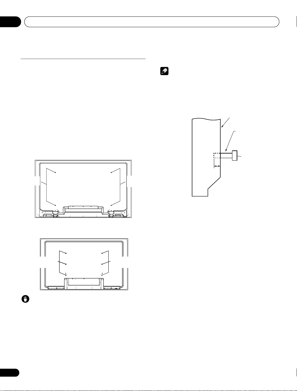
When using other items
• Consult your dealer.
• The following mounting holes can be used for the installation:
Rear view
(KRP-600P)
(KRP-500P)
• Do not mount or remove the display panel to or from the stand,
with speakers attached.
Note
• It is strongly recommended to use the optional Pioneer
mounting products.
• Pioneer shall not be liable for any personal injury or product
damage that results from the use of mounting items other than
the optional Pioneer products.
Side view
10
En
Caution
• Use M8 screws, which go 12 mm to 18 mm in depth from the
mounting surface of the display panel. See the side view shown
to the right.
• Be careful not to block the ventilation opening at the rear of the
display panel.
• Be sure to install the display panel on a flat surface because it
contains glass.
• The screw holes other than the illustrations above are to be
used only for the specified products. Never use them for
mounting non-specified products.
Page 11
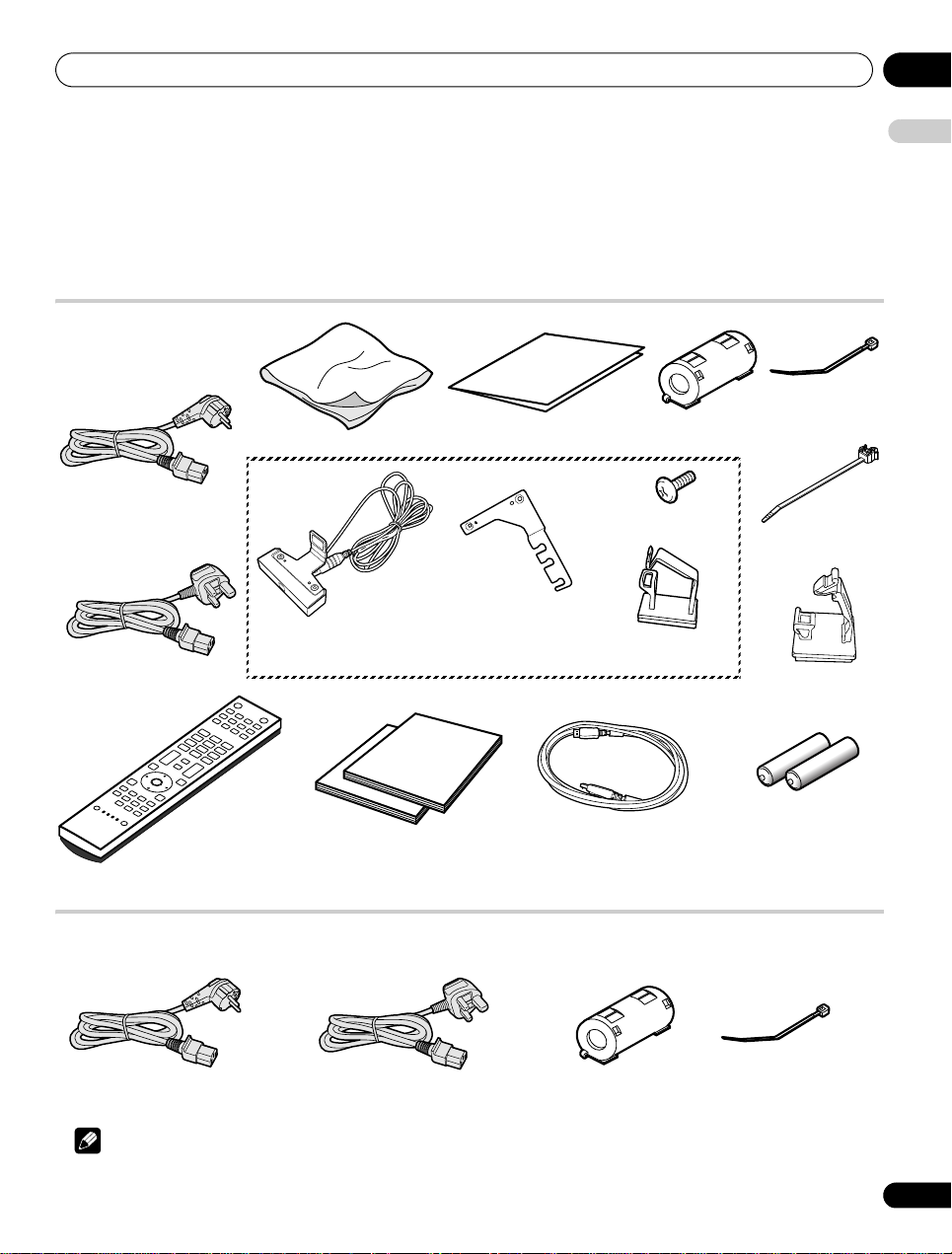
Supplied accessories 03
For Europe, except UK and
Republic of Ireland
For UK and Republic of Ireland
Cable clamp x 4
Cleaning cloth
Warranty card
Power cable
Only the power cable
appropriate for your country
or region is supplied:
Screw x 2 (M5 x 8 mm)
Colour Sensor Bracket
(when attached to the top
right of the rear panel)
Colour Sensor
Cable guide
Cable tie
(for ferrite core)
Cable guide x 2
(KRP-500P only)
Remote control unit
AA size battery x 2
(for remote control unit)
SYSTEM cable
Operating instructions x 2
Ferrite core x 2
(Grey x 1, Black x 1)
For Europe, except UK and
Republic of Ireland
For UK and Republic of Ireland
Power cable
Only the power cable appropriate for your country or region is supplied:
Ferrite core
Cable tie
(for ferrite core)
Chapter 3
Supplied accessories
Check that all of the following accessories are supplied in the box.
Display
English
Media Receiver
Note
• Always use the power cord supplied with the display and the one supplied with the Media Receiver for each respective unit.
11
En
Page 12
Part names04
(KRP-600P)
Bottom
(upper bank)
(KRP-600P)
Viewed from the
underside of the
display
Chapter 4
Part names
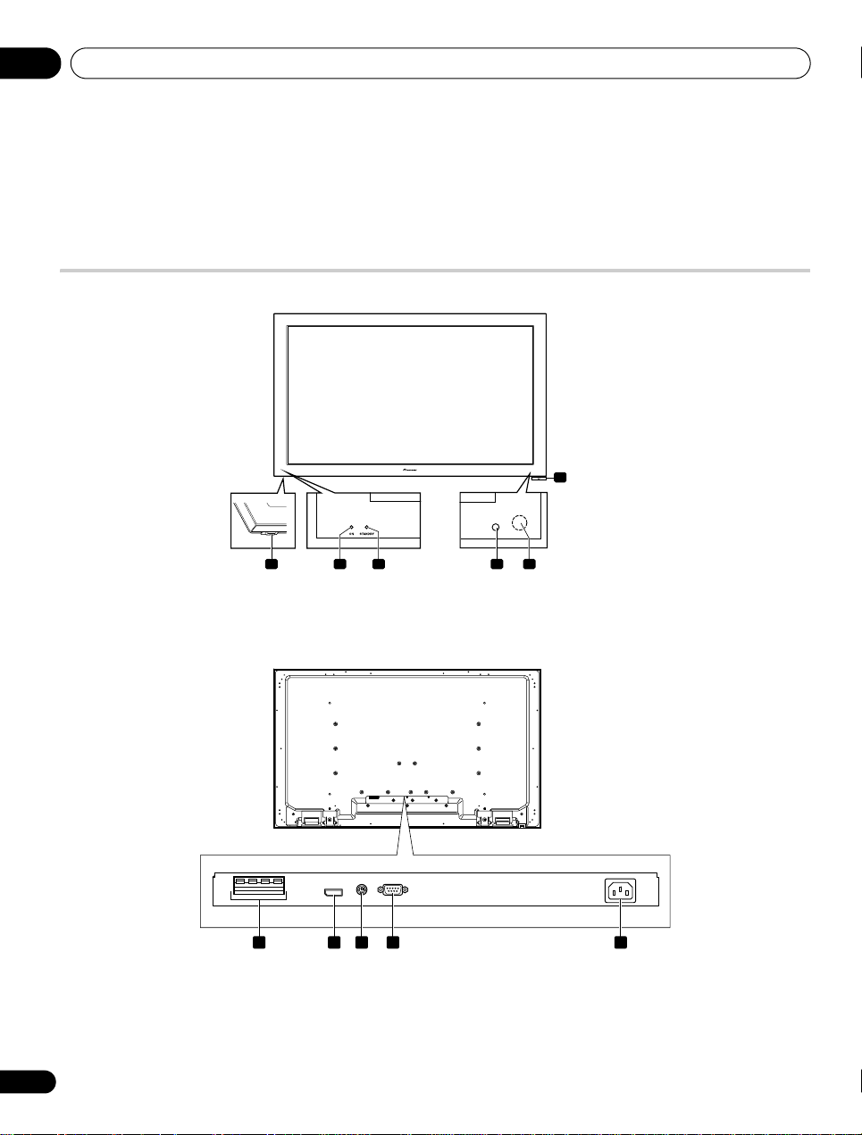
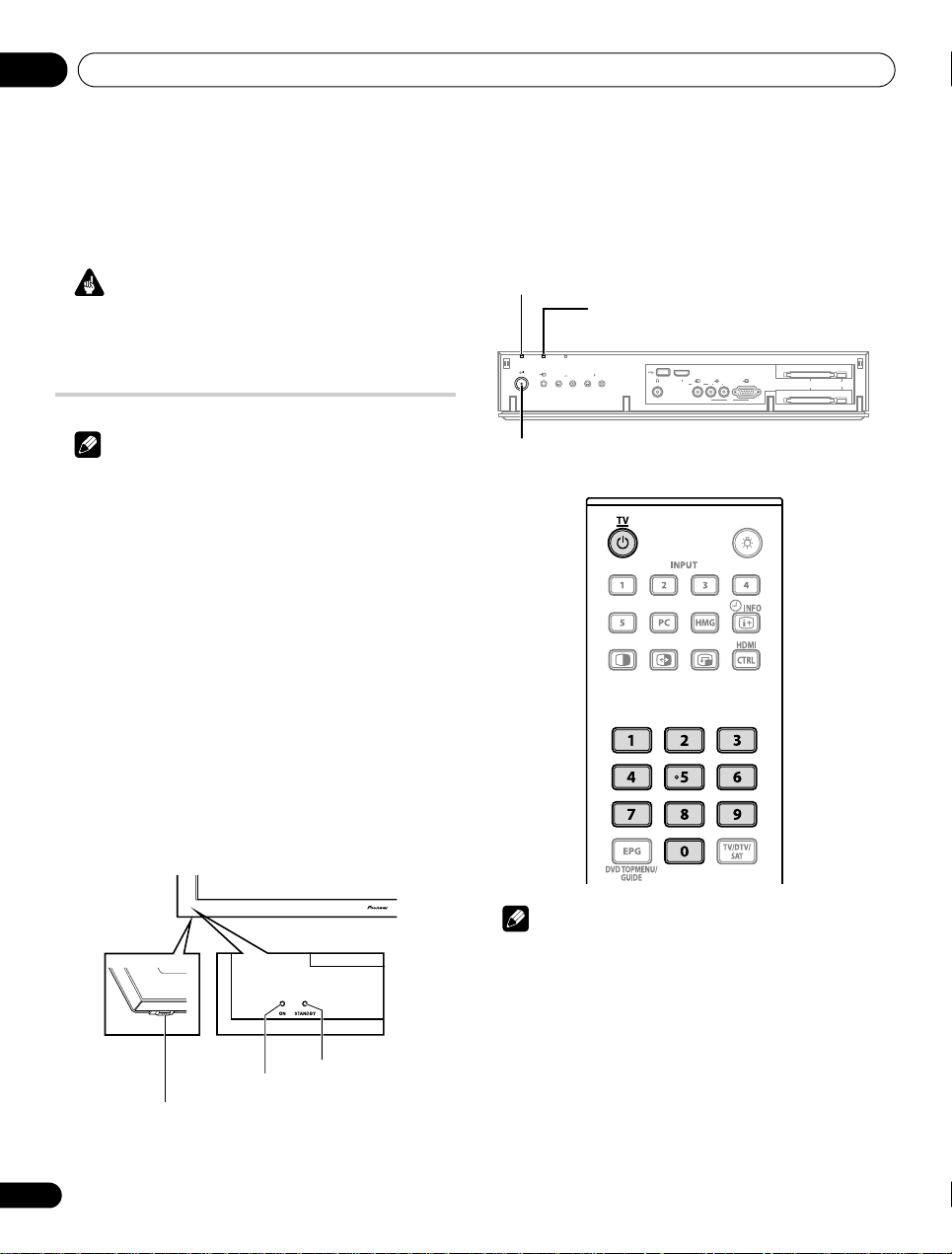
Display
(Front)
6
1 Power On (a) button
2 Power ON indicator
3 STANDBY indicator
1 54
2 3
(Rear)
1
1 SPEAKERS terminals (right/left)
• Do not connect any devices to the speaker terminals other than
the speakers specified.
• Do not leave speaker cable wires bare and exposed at the
terminals. Exposed wires can result in an electrical short
causing malfunction or damage to the system.
2
3
4 Room Light sensor
5 Remote Control sensor
6 Colour sensor
4
2 SYSTEM CABLE terminal
3 Colour sensor terminal
4 RS-232C terminal (SERVICE ONLY)
(used for factory setup)
5 AC IN terminal
5
12
En
Page 13
Part names 04
STANDBY/ON
INPUT
ON STANDBY TIMER
VOLUME CHANNEL
PHONES
USB HDMI
INPUT 5 VIDEO ANALOG RGBL AUDIO
R
PC
KRP-M01
COMMON INTERFACE 2 SATELLITE
COMMON INTERFACE 1 TERRESTRIAL
EJECT
PULL OPEN
7
1 2 3 4 5 6
8 9 10 13
11 12 14 15
AC IN
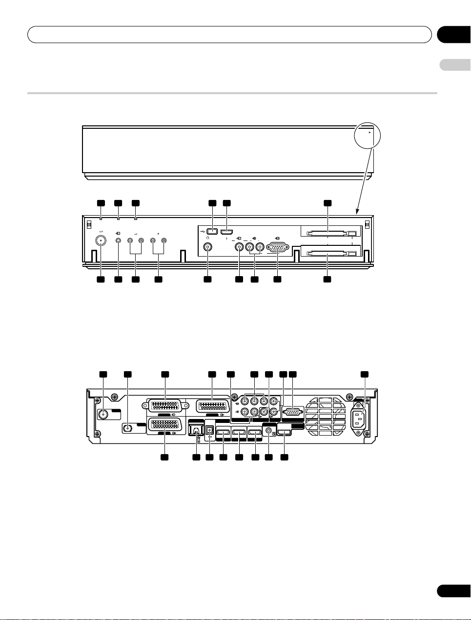
Media Receiver
(Front)
English
1 Power ON indicator
2 STANDBY indicator
3 TIMER indicator
4 USB port
5 INPUT 5 terminal (HDMI)
6 COMMON INTERFACE 2 SATELLITE slot
7 STANDBY/ON button
8 INPUT button
(Rear)
1 2 3
ANT
1 ANT (Antenna) input terminal
2 SAT (Satellite) input terminal
3 INPUT 1 terminal (SCART)
4 INPUT 2 terminal (SCART)
5 INPUT 2 terminals (Audio)
6 INPUT 2 terminals (COMPONENT VIDEO: Y, P
7 SUB WOOFER OUT terminal
8 AUDIO OUT terminals
9 RS-232C terminal (SERVICE ONLY)
(used for factory setup)
INPUT 1
SAT
INPUT 3
INPUT 2
LAN (10 / 100)
OPTICAL
1211 13 14 15 16 17 18
, PR)
B
9 VOLUME Up/Down buttons
10 CHANNEL Up/Down buttons
11 PHONES output terminal
12 INPUT 5 terminal (Video)
13 INPUT 5/PC INPUT terminals (Audio)
14 PC INPUT terminal (Analogue RGB)
15 COMMON INTERFACE 1 TERRESTRIAL slot
4 5 6 987 10
R
P
PBY
L
COMPONENT VIDEO
R
LRAUDIO
AUDIO OUT
SUB WOOFER OUT
INPUT 2
DIGITAL OUT
HDMI
HDMI
HDMI
INPUT 1
INPUT 4
INPUT 3
10 AC IN terminal
11 INPUT 3 terminal (SCART)
12 LAN (10/100) port
13 DIGITAL OUT terminal (OPTICAL)
14 INPUT 1 terminal (HDMI)
15 INPUT 3 terminal (HDMI)
16 INPUT 4 terminal (HDMI)
17 CONTROL OUT terminal
18 SYSTEM CABLE terminal
OUT
CONTROL
SERVICE ONLY
SYSTEM
CABLE
13
En
Page 14
Part names04
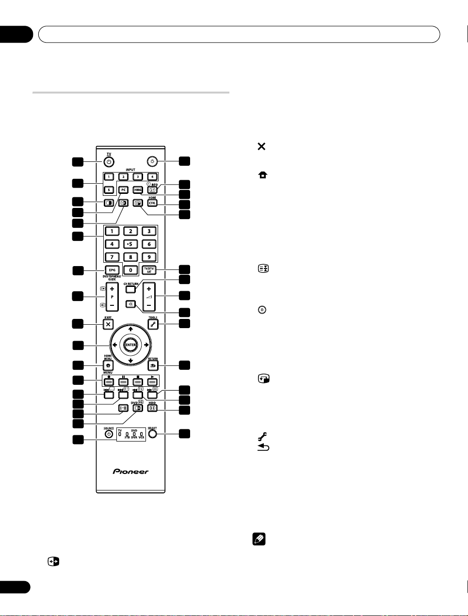
Remote control unit
This section describes the functions of the buttons available when
the TV mode has been selected by using the SELECT button. For the
buttons controlling other equipment, see Controlling other
equipment using the supplied remote control unit starting from
page 90.
1
2
3
4
18
19
20
21
22
5
6
7
23
24
2
8
25
26
2
9
27
10
11
28
12
13
14
15
29
30
31
16
17
1 TV : Turns on the power to the flat screen TV or places it
into the standby mode.
2 INPUT: Selects an input source of the flat screen TV. (“INPUT
1”, “INPUT 2”, “INPUT 3”, “INPUT 4”, “INPUT 5”)
3 c: Switches the screen mode among 2-screen, picture-in-
picture, and single-screen.
4PC: Selects the PC terminal as an input source.
5: Switches between the two screens when in the 2-screen
or picture-in-picture mode.
32
60 to 9: TV/External input mode: Selects a channel.
Teletext mode: Selects a page.
Turns the power on when the STANDBY indicator lights red.
7 EPG: Displays the Electronic Programme Guide in DTV/SAT
(Satellite) input mode.
8P+/P–: TV/External input mode: Selects a channel.
w/x: Teletext mode: Selects a page.
9EXIT: Returns to the normal screen in one step.
10 ///: Selects a desired item on the setting screen.
ENTER: Executes a command.
11 HOME MENU: Displays the HOME MENU screen.
12 Colour (RED/GREEN/YELLOW/BLUE):
Controls a BD player for HDMI Control functions only.
13 [: Jumps to Teletext subtitle page.
Turns subtitle on and off in DTV input mode depending on the
broadcast.
14 k: Displays hidden characters.
15 g: Sets the sound multiplex mode.
16 d: TV/External input mode: Freezes a frame from a moving
image. Press again to cancel the function.
: Teletext mode: Stops updating Teletext pages. Press
again to release the hold mode.
17 TV, STB, DVD/DVR, VCR: These indicators show the
current selection and status when you control other connected
equipment, using the supplied remote control unit.
18 : Lights up buttons.
Lights turn off if no operations are performed within five
seconds. This is used for remote control use in dark locations.
19 p y INFO: Displays the channel information.
Displays the banner information.
20 HMG (Home Media Gallery): Displays the Home
Media Gallery screen.
21 HDMI CTRL: Displays the HDMI Control menu.
22 : Moves the location of the small screen when in the
picture-in-picture mode.
23 TV/DTV/SAT: Switches the mode among TV, DTV and SAT.
24 CH RETURN: Returns to the previous channel.
25 i +/i –: Sets the volume.
26 e: Mutes the sound.
27 TOOLS: Displays the TOOLS Menu.
28 RETURN: Restores the previous menu screen.
29 m: Selects the Teletext mode (all TV image, all TEXT image,
TV/TEXT image).
30 l: Displays an Index page for the CEEFAX/FLOF format.
Displays a TOP Over View page for the TOP format.
31 f: Selects the screen size.
32 SELECT: Switches the selection among TV, STB, DVD/DVR,
and VCR, so that you can control other connected equipment,
using the supplied remote control unit.
Note
• When using the remote control unit, point it at the display
panel.
14
En
Page 15
Preparation 05
Over 50 cm
Over
10 cm
SYSTEM cable
Display
Media Receiver
Over 5 cm
Over 5 cm
Over 5 cm
Over 10 cm
Exhaust opening
Ventilation opening
Chapter 5
Preparation
English
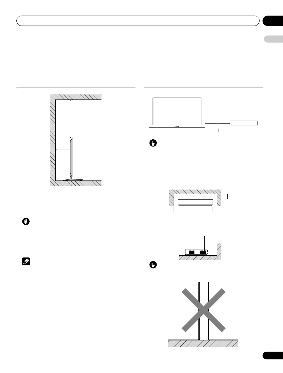
Installing the display
Location
• Avoid direct sunlight. Maintain adequate ventilation.
• The length of the SYSTEM cable used to connect the display and
the Media Receiver is about 3 m.
Caution
• If you do not leave sufficient space above the display, it will not
receive enough ventilation and will not operate properly.
• Pioneer will not be responsible for accident or damage caused
by inadequate installation or stabilization, erroneous operation,
remodeling or natural disasters.
Installing the Media Receiver
Caution
• Do not use the SYSTEM cable to connect other equipment to the
flat screen TV.
• Do not place a VCR or any other device on the top of the Media
Receiver.
• When installing, allow enough space on the sides and above the
Media Receiver.
• Do not block the side ventilation openings or the rear exhaust
openings of the Media Receiver.
Note
• Allow enough space around the upper and back parts when
installing to ensure adequate ventilation of the rear of the unit.
• Be sure to install the display and Media Receiver in a flat, stable
location.
Using the optional Pioneer stand
For details on installation, refer to the instruction manual supplied
with the stand.
Using the optional Pioneer speakers
For details on installation, refer to the instruction manual supplied
with the speakers.
Caution
• Placing the Media Receiver alone in the vertical position can
result in product damage and malfunction.
15
En
Page 16
Preparation05
(KRP-600P)
(KRP-500P)
(KRP-600P)
8 mm to 15 mm
20 mm min.
4 mm
Wood screw
(commercially available,
4 mm x 20 mm min.)
Falling prevention
metal fitting
(KRP-500P)
Wood screw
(commercially available,
4 mm x 20 mm min.)
Falling prevention
metal fitting
8 mm to 15 mm
20 mm min.
4 mm
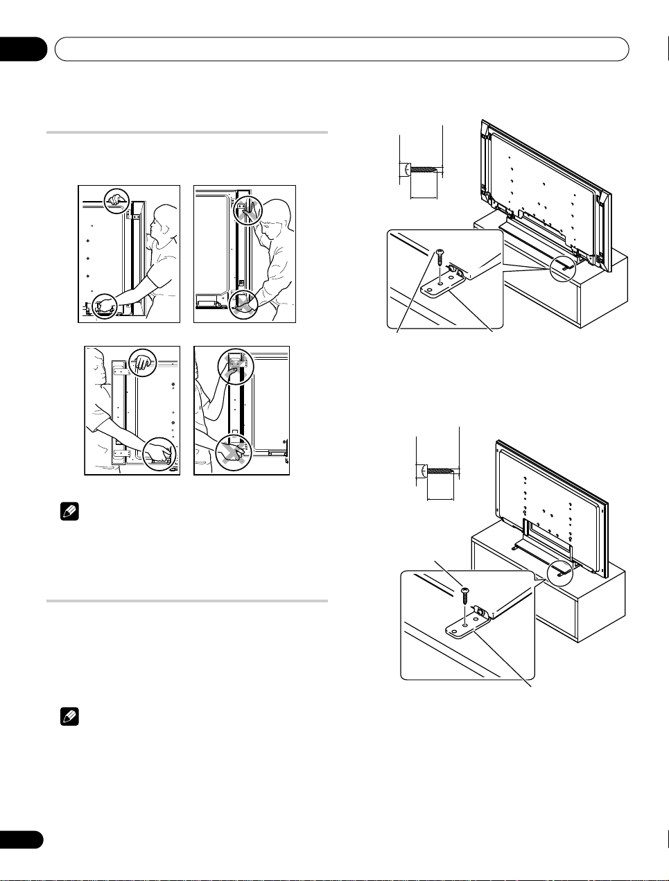
Moving the display
When installing on a rack, etc., hold the display as shown below.
Because the display is heavy, be sure to have someone help you
when moving it.
Drill a hole in the middle at the rear of the tabletop panel before
using a wood screw. Perform this work the same way on the left and
right sides.
Note
• Do not use the speaker to support the weight of the display.
• Do not hold the display by the speaker mounting fittings.
Preventing the display from falling
over
After installing the stand, be sure to take special care to ensure that
the display will not fall over and is stabilized to both the wall and
rack.
Stabilizing on a table or rack
Stabilize the display as shown in the diagram using the falling
prevention metal fittings and screws supplied with the optional
stand.
16
En
Note
• Before stabilizing the display on a stand or rack, make sure that
the falling prevention metal fittings are attached to the stand.
• To stabilize the display on a table or rack, also use commercially
available wood screws that have a nominal diameter of 4 mm
and that are at least 20 mm long.
Drill a hole in the middle at the rear of the tabletop panel before
using a wood screw. Perform this work the same way on the left and
right sides.
Page 17
Preparation 05
1. Hook
Fitting
12 mm to 18 mm
M 8
2. Cord
Magnet
(Front)
(Rear)
Display
Colour
sensor
Colour sensor cable
Cable clamp
Colour sensor terminal
(upper bank)
Colour sensor
Cable guide (supplied with the colour sensor)
(KRP-600P)
Colour sensor cable
Cable clamp
Colour sensor terminal
(upper bank)
Colour sensor
Cable guide (supplied with the colour sensor)
(KRP-500P)
Cable guide (supplied with the flat screen TV)
Attach the cable guides here to bundle the
colour sensor cable.
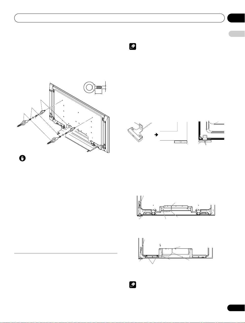
Using a wall for stabilization
1 Attach falling prevention bolts (hooks) to the display.
2 Use strong cords to stabilize it appropriately and firmly to a
wall, pillar, or other sturdy element.
Perform this work in the same way on the left and right sides.
Use hooks, cords and fittings that are available on the market.
Recommended hook: Nominal diameter 8 mm, length 12 mm to
18 mm
Note
• Do not connect any other external device to the colour sensor
terminal.
• Do not connect the colour sensor cable to any devices other
than specified.
• To clean the sensor window, gently wipe with the cleaning cloth
supplied with the panel.
• Do not use extension cables for the colour sensor.
• Do not disassemble or modify the colour sensor.
Attach the colour sensor to the front panel
(recommended)
This is a simple and easy-to-attach method using a magnet.
1 Attach the colour sensor at the bottom right of the front panel
using a magnet.
English
Caution
• A tab le or rac k wi th ad equ ate s tre ngth s houl d al way s be u sed to
support the display. Failure to do so could result in personal
injury and physical damage.
• When installing the display, please take the necessary safety
measures to prevent it from falling or overturning in case of
emergencies, such as earthquakes, or of accidents.
• If you do not take these precautions, the display could fall down
and cause injury.
• The screws, hooks, cords and other fittings that you use to
secure the display to prevent it from overturning will vary
according to the composition and thickness of the surface to
which it will be attached.
• Select the appropriate screws, hooks, cords, and other fittings
after first inspecting the surface carefully to determine its
thickness and composition and after consulting a professional
installer if necessary.
• Do not use bare wires for the cord. If any part of the wire is
introduced into the ventilation port on the back of the display
panel, fire or electrical shock could result.
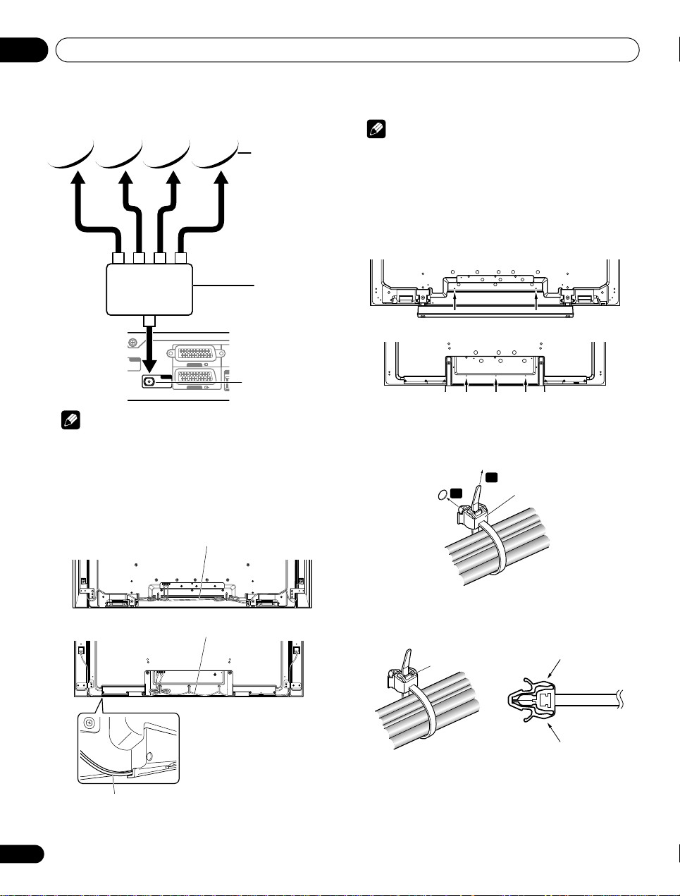
Attach the colour sensor
When attached to your panel, the colour sensor analyses the
brightness of the environment to automatically optimize the picture
quality according to the viewing condition. To activate this function,
select OPTIMUM on the AV Selection menu, Mode 1 or Mode 2 on
the Room Light Sensor menu (page 62).
We strongly suggest you attach the colour sensor to the bottom
right of the front panel. It can be attached to the rear of the panel,
but the colour sensor may not operate properly depending on the
conditions (refer to the Important bullets on page 19). For the actual
procedure, follow the directions below.
2 Attach the colour sensor along the bottom edge of the front
panel flush with the right side.
When the colour sensor is properly attached, the front of the colour
sensor is set back a small amount from the front of the display.
3 Connect the cable to the colour sensor terminal on the rear
upper bank but do NOT plug in to the power outlet.
Note
• Use the cable clamps as necessary.
• Remove the sheet of the double-sided adhesive tape when
attaching the cable guide to the panel.
17
En
Page 18
Preparation05
(Bracket)
Colour sensor cable
Cable clamp
Colour sensor terminal
(upper bank)
Cable clamp
Colour sensor
Speaker cable
Cable guide
(supplied with the
colour sensor)
Cable guide (supplied
with the flat screen TV)
(KRP-600P)
Colour sensor terminal
(upper bank)
Colour sensor cable
Cable clamp
(KRP-500P)
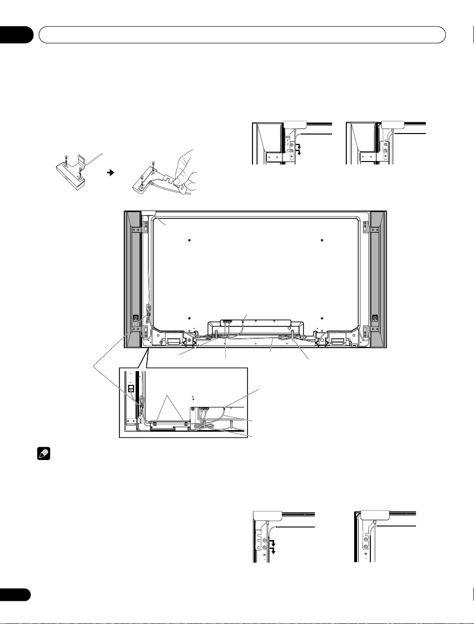
Attach the colour sensor to the rear panel
Methods of attaching the colour sensor to the rear panel differ
depending on the panel with or without side-mounted speakers.
(when side-mounted speakers are installed)
1 Remove the screws of the colour sensor then replace the
bracket.
Use the removed screws again.
2 Loosen the upper two (2) speaker bracket screws.
3 Fit the colour sensor bracket’s lower grooves into the screws.
Adjust the colour sensor/speaker bracket positions so as to stay in
place.
4 Fasten the screws.
5 Connect the cable to the colour sensor terminal on the rear
upper bank but do NOT plug in to the power outlet.
Note
• Do not loosen the screws at the bottom of the panel. When attached to the rear panel, the sensor window points upward.
• If the colour sensor attached to the rear panel does not operate properly, attach it to the front panel.
• Do not use the supplied screws when attaching the colour sensor using the speaker brackets.
• The colour sensor may become hot due to a heat emitted from the panel. When using it in a high-temperature environment, attach the
colour sensor to the bottom of the front panel.
(when side-mounted speakers are not installed)
1 Remove the screws of the colour sensor then replace the
bracket.
Use the removed screws again.
2 Finger tighten the supplied colour sensor screws in the
speaker screw holes.
3 Fit the colour sensor bracket’s lower grooves into the screws.
Adjust the bracket position to stay in place.
4 Fasten the screws.
18
En
5 Connect the cable to the colour sensor terminal on the rear
upper bank but do NOT plug in to the power outlet.
Page 19
Preparation 05
C
P
Standard DIN45325 plug (IEC169-2)
75-ohm coaxial cable (round cable)
(commercially available)
Media Receiver (rear)
Direct connection to the Media Receiver
Satellite antenna
SAT (Satellite)
input terminal
Using Tone Burst
SAT (Satellite)
input terminal
Satellite antenna
SW (Tone Burst)
Important
The colour sensor may not operate properly:
• if attached by methods other than specified above
• if anything blocks light falling on the sensor window
• if light falls on only part of the sensor window
• if the light falling on the sensor window and the panel screen
differs
Note
• If the colour sensor attached to the rear panel does not operate
properly, attach it to the front panel.
• The colour sensor may become hot due to a heat emitted from
the panel. When using it in a high-temperature environment,
attach the colour sensor to the bottom of the front panel.
• Do not use the screws supplied for the speakers.
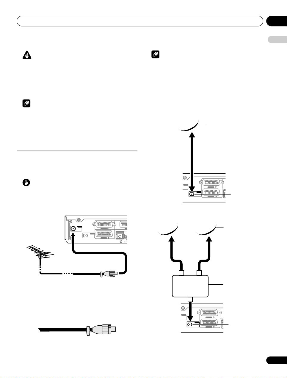
Basic connections
Connecting the antenna
To enjoy a clearer picture, use an outdoor antenna. The following is
a brief explanation of the types of connections that are used for a
coaxial cable.
Caution
• When the “Aerial Power” setting is on, directly connect the
aerial to the ANT input terminal at the rear of the Media
Receiver. Connecting any device between the aerial and Media
Receiver may cause damage to the device.
Note
• If the antenna is not connected correctly, the quality of reception
may be impaired. If images are not displaying correctly, check
whether the antenna connection is correct or not.
Connecting the satellite antenna
There are three different connection methods available as shown
below. Select the appropriate menu according to the swi tch you use.
Setting up satellite TV channels manually
See
details on how the antenna is connecte d (in a building, for example),
select “SMATV” from “Scan Type” on the “Satellite Setup” menu.
ANT
INPUT 1
SAT
INPUT 3
on
page 33
. If no
LA
English
ANT
INPUT 1
SAT
LAN (10 / 100)
INPUT 3
• Connect a 75-ohm coaxial cable (commercially available) to the
ANT terminal.
• If “Aerial Power” setting is enabled, use an indoor antenna with
signal amplifier, 5 V 30 mA.
Antenna cable (commercially available)
If your outdoor antenna uses a 75-ohm coaxial cable with a
standard DIN45325 plug (IEC169-2), plug it into the antenna
terminal at the rear of the Media Receiver.
IN
OPTI
ANT
INPUT 1
SAT
LA
INPUT 3
19
En
Page 20
Preparation05
SAT
ANT
LA
INPUT 3
INPUT 1
Using DiSEqC switch
SAT (Satellite)
input terminal
Satellite antenna
SW (DiSEqC)
Speaker cable
(KRP-600P)
(KRP-500P)
Speaker cable
The groove at the bottom is for
speaker cables.
Do not insert the colour sensor
cable in the groove.
Speaker cable
(KRP-600P)
(KRP-500P)
Cable clamp
Latch
Lever
Lever
Note
• Do not make the following connections:
– using two or more switches
– connecting the Media Receiver and antenna through an STB
– using a motorized antenna
Routing cables
When the speaker is mounted to the display panel:
Note
• Use the supplied cable clamps as necessary.
• When tidying up your speaker cables, make sure to bundle them
so that they are not subjected to any pressure.
Attaching cable clamps to the main unit
Use the cable clamps as necessary to route the connecting cables.
The diagrams below show the location of the holes on the rear of the
display.
Attaching and removing a cable clamp
Thread the clamp band through the holder [1] and bundle the
cable(s) in the cable clamp. Push and hold the levers then insert the
hook into an appropriate hole [2] on the rear of the display. Pull up
the clamp band to lock.
1
2
20
En
• Confirm that the cable clamp is seated firmly in the panel.
To remove the clamp band, pull and hold the latch to release.
To remove the cable clamp, push and hold the levers then pull it out
from the hole.
Page 21
Preparation 05
1
2
3
4
Ferrite core
To power outlet
AC power cord
As close as possible
Cable tie
To display and
Media Receiver
AC IN
Connecting the SYSTEM cable to the Media Receiver
Connecting the SYSTEM cable to the display
Media Receiver (rear)
SYSTEM cable
Display (rear)
Connecting the SYSTEM cable
Note
• Avoid pinching or creating pressure points when routing or
bundling cables.
• The longer a clamp is in place, the better chance of
deterioration. An older clamp is more easily damaged while
being removed and may not be reusable.
• Use the cable clamps as necessary.
• Be careful not to subject any connecting cables to strain.
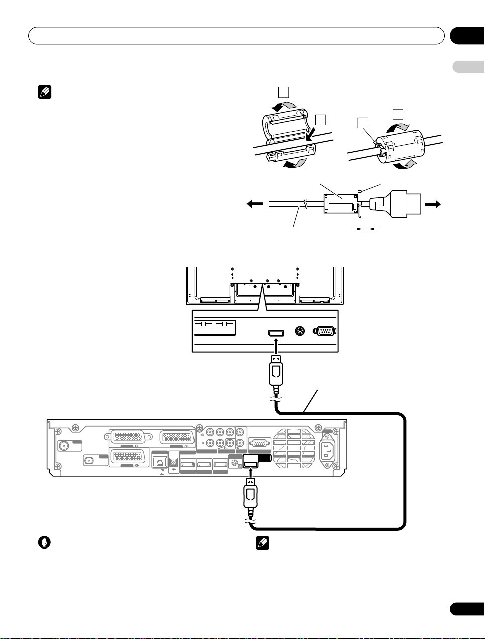
Attaching the ferrite core
Attach the accessory ferrite core to the end of the display and the
Media Receiver’s power cords as shown in the accompanying
illustration. Use the provided cable tie to prevent the ferrite core
from slipping on the cable.
If you do not do this, the flat screen TV will not conform to
mandatory CE standards.
English
ANT
INPUT 1
SAT
INPUT 3
Caution
• Do not use the SYSTEM cable to connect other equipment to the
flat screen TV.
LAN (10 / 100)
R
P
OPTICAL
PBY
INPUT 2
DIGITAL OUT
INPUT 1
LRAUDIO
INPUT 2
HDMI
HDMI
INPUT 3
COMPONENT VIDEO
SUB WOOFER OUT
HDMI
INPUT 4
OUT
CONTROL
AUDIO OUT
L
R
SERVICE ONLY
SYSTEM
CABLE
Note
• The SYSTEM cable comes with the same terminals on both
ends.
• Do not connect an HDMI cable to the SYSTEM CABLE terminal.
• When removing the SYSTEM cable, push and hold the latch on
the connector to release.
21
En
Page 22
Preparation05
Display (rear)
Power cord
UK and Republic of Ireland
Europe, except UK
and Republic of
Ireland
Media Receiver (rear)
Power cord
UK and Republic of Ireland
Europe, except UK
and Republic of
Ireland
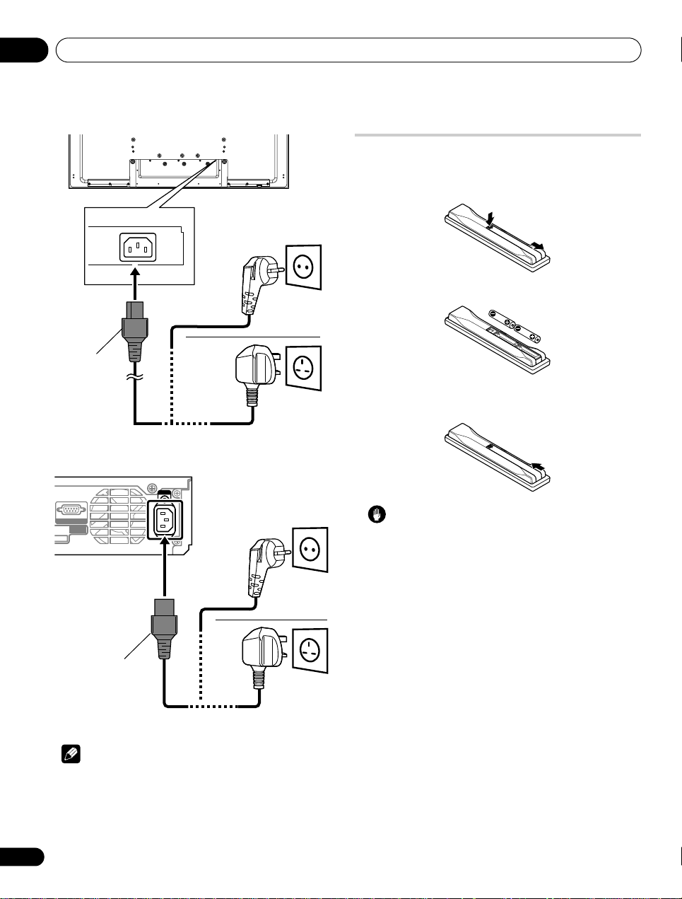
Connecting the power cord
SERVICE ONLY
SYSTEM
CABLE
Note
• Disconnect the power cord from the power outlet when the flat
screen TV is not going to be used for a long period of time.
• Insert the power plug in the AC outlet, after all other
components are connected.
AC IN
Preparing the remote control unit
Inserting batteries
1 To open push and slide the battery cover in the direction of
the arrows.
2 Load the supplied two AA size batteries while inserting
their respective negative polarity (–) ends first.
Place batteries with their terminals corresponding to the (+) and (–)
indicators in the battery compartment.
3 Close the battery cover.
Caution
Improper use of batteries can result in chemical leakage or an
explosion. Be sure to follow the instructions below.
• When you replace the batteries, use manganese or alkaline
ones.
• Place the batteries with their terminals corresponding to the (+)
and (–) indicators.
• Do not mix batteries of different types. Different types of
batteries have different characteristics.
• Do not mix old and new batteries. Mixing old and new batteries
can shorten the life of new batteries or cause chemical leakage
in old batteries.
• Remove batteries as soon as they have worn out. Chemicals
that leak from batteries can cause a rash. If you find any
chemical leakage, wipe thoroughly with a cloth.
• The batteries supplied with this product may have a shorter life
expectancy due to storage conditions.
• If you will not use the remote control unit for an extended period
of time, remove the batteries from it.
• WHEN DISPOSING OF USED BATTERIES, PLEASE COMPLY
WITH GOVERNMENTAL REGULATIONS OR
ENVIRONMENTAL PUBLIC INSTITUTION’S RULES THAT
APPLY IN YOUR COUNTRY/AREA.
22
En
Page 23
Preparation 05
Remote
control
sensor
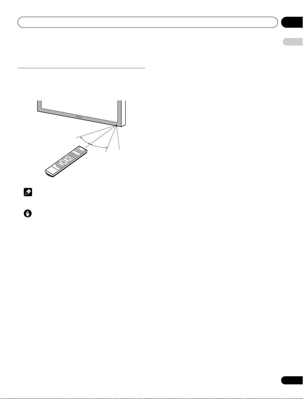
Operating range of the remote control
unit
Operate the remote control unit while pointing it toward the remote
control sensor located at the bottom right of the front panel of the
display. The distance from the remote control sensor must be within
7 m and the angle relative to the sensor must be within 30 degrees
in the right, left, upward, or downward direction.
English
30º
Note
• For remote control sensor locations, see Part names on page 12.
Caution
• Do not expose the remote control unit to shock. In addition, do
not expose the remote control unit to liquids, and do not place
in an area with high humidity.
• Do not install or place the remote control unit under direct
sunlight. The heat may cause deformation of the unit.
• The remote control unit may not work properly if the remote
control sensor of the display is under direct sunlight or strong
lighting. In such case, change the angle of the lighting or
display, or operate the remote control unit closer to the remote
control sensor.
• When any obstacle exists betwe en the remote control unit and the
remote control sensor, the remote control unit may not function.
• As the batteries become empty, the remote control unit can
function within a shorter distance from the remote control
sensor. Replace the batteries with new ones early enough.
• The display emits very weak infrared rays from its screen. If you
place such equipment operated through infrared remote
control as a VCR nearby, that equipment may not receive
commands from its remote control unit properly or entirely. If
this is the case, place that equipment at a location far enough
from the flat screen TV.
• Depending on the installation environment, infrared rays from
the display may not allow this system to properly receive
commands from the remote control unit or may shorten
allowable distances between the remote control unit and the
remote control sensor. The strength of infrared rays emitted
from the screen differs, depending on images displayed on the
screen.
7 m
30º
23
En
Page 24
Watching TV06
Power On (a) button
Power ON indicator
STANDBY indicator
Display
STANDBY/ON
INPUT
ON STANDBY TIMER
VOLUME CHANNEL
PHONES
USB HDMI
INPUT 5 VIDEO ANALOG RGBLAUDIOR
PC
KRP-M01
COMMON INTERFACE 2 SATELLITE
COMMON INTERFACE 1 TERRESTRIAL
EJECT
STANDBY/ON button
Power ON indicator
STANDBY indicator
Media Receiver (front)
Chapter 6
Watching TV
Important
• Before watching broadcast channels, the built-in TV tuner must
be set up. See Setting up TV channels on page 33 for how to do
this.
Turning the power on/off
Note
• When the Media Receiver is plugged into a power outlet, it is
placed into standby mode; the STANDBY indicator on its front
panel should flash red. The Media Receiver stays in standby
mode unless it is unplugged from the power outlet.
To turn on the system, press the Power On (a) button on the
display.
• The Power ON indicators on the display and Media Receiver
light up blue.
a
To turn off the system, press
STANDBY/ON
• The display and Media Receiver are placed into standby mode;
their respective STANDBY indicators light up red.
• You can then turn on the system again by pressing
on the remote control unit or
on the Media Receiver.
Receiver.
• If you press
0
on the remote control unit, images from “INPUT 1”
will be displayed.
• If you press
You can also press the Power On (a) button on the display to turn
off the system. However, you cannot then turn on the system again
by pressing the buttons on the remote control unit and Media
Receiver.
1
to 9, TV images will be displayed.
on the remote control unit or
a
STANDBY/ON
or 0 to 9
on the Media
24
En
Note
•When
the Power On (a)
turn the power on by pressing
STANDBY/ON
unit or
• While the system is placed into standby mode, pressing remote
• When the system is placed into standby mode, the main power
a
control’s
causes the flat screen TV to turn on.
flow is cu t and the s yste m is n o longer fully operational. A minute
button on the
a
on the
Media Receiver
display
or 0 to 9 on the remote control
is off, you cannot
.
flow of power feeds the system to maintain operational readiness.
• If you are not going to use the
flat screen TV
for a long period of
time, be sure to remove the power cord from the power outlet.
Page 25
Watching TV 06
INPUT
CHANNEL+/–
Media Receiver (front)
• If you unplug the
inside the
recording, disabled. After plugging in the
clock information is automatically obtained as you tune in a DTV
programme.
Media Receiver
system
will reset with certain functions, such as timer
from a power outlet, the clock
Media Receiver
again,
If you unplug the
timer recording programme(s) has been registered, the
screen TV
order to obtain clock information when you turn the power on the
next time.
It may take a short while until the clock information is obtained.
An alert will appear when you try to tune in an analogue
programme before obtaining the clock information.
Media Receiver
may automatically tune in to the DTV programme in
from a power outlet when a
flat
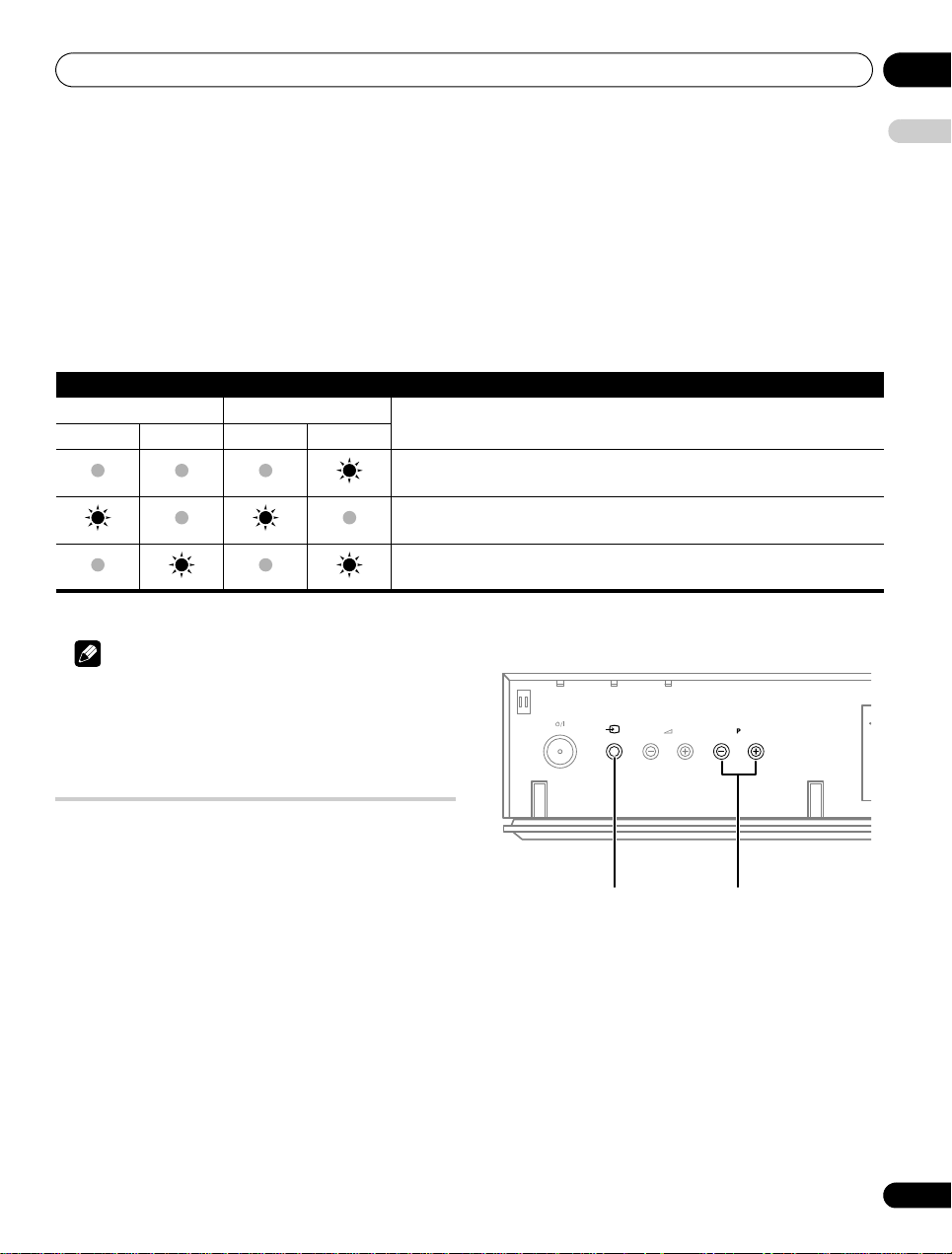
Flat screen TV status indicators
The table below shows the operational status of the flat screen TV. You can check the current status of the system with the indicators on the
display and Media Receiver.
Indicator status System status
Display Media Receiver
Power ON STANDBY Power ON STANDBY
The power cord of both the display and Media Receiver have been connected but
the Power On (a) button of the display is off.
Power to the system is on
The system is in standby mode
For other than the above, see Troubleshooting on page 102.
Note
• You can select “Auto”, “High”, “Mid” or “Low” for the brightness
of the Power ON indicator. When “Auto” is selected, the
brightness of the indicator changes to “High”, “Mid” or “Low” to
match the brightness level of the viewing area. For details, see
Blue LED Dimmer on page 62.
ON STANDBY TIMER
STANDBY/ON
INPUT
VOLUME CHANNEL
English
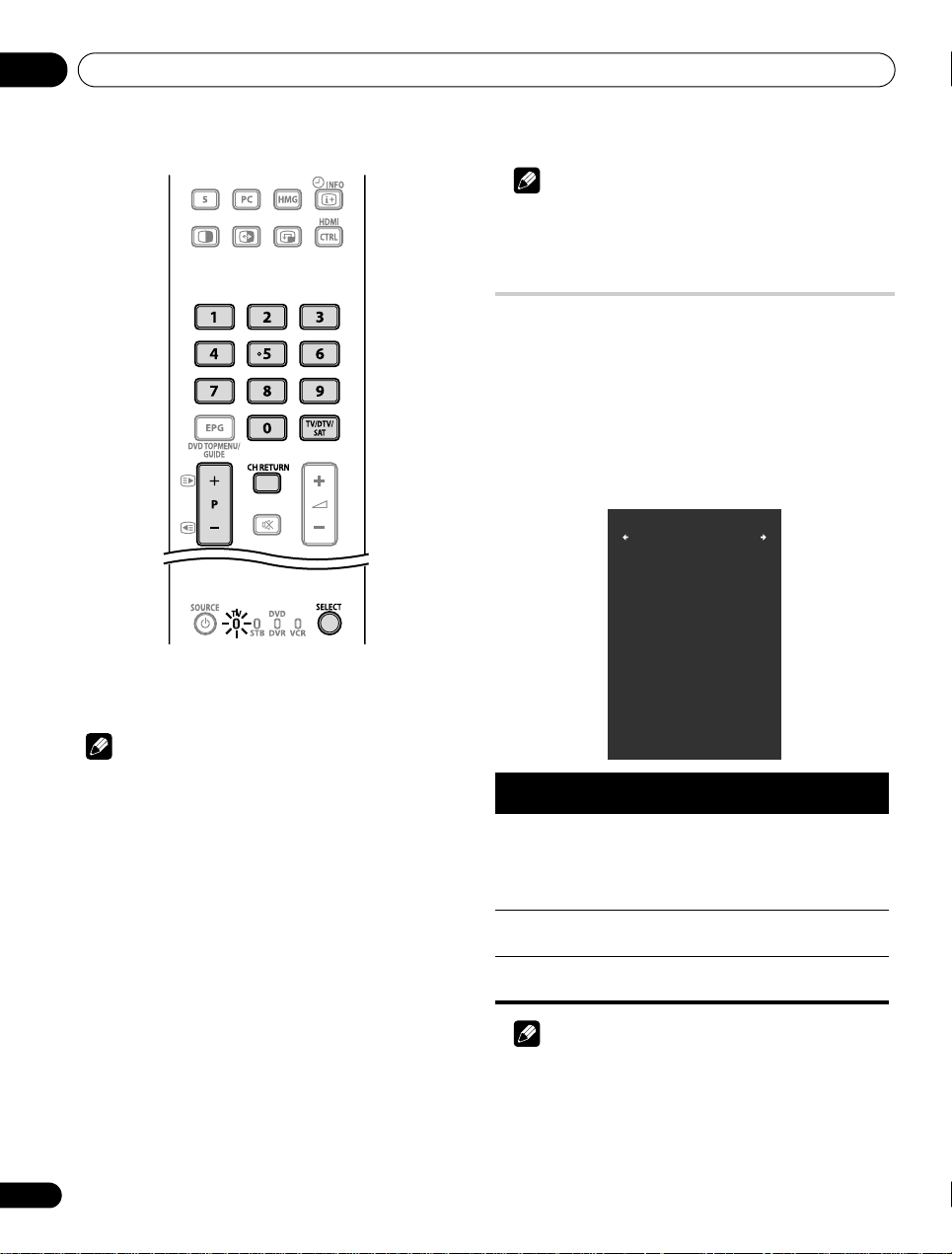
Changing channels
Use the remote control or the control panel of the Media Receiver
to change channels.
• Before operating wi th the remote control unit, make sure to select
the TV mode using its
equipment using the supplied remote control unit
Switching the TV input mode
• Press INPUT on the Media Receiver or TV/DTV/SAT on the
remote control unit to select TV, DTV or SAT (satellite) input
mode.
SELECT
button. See
Controlling other
on page 90.
25
En
Page 26
Watching TV06
Favourites
Input5
XXXX 0100
XXXX 020
XXXX 0055
Home Media Gallery
PC
XXXX 0211
XXXX 1050
XXXX 001
XXXX 030
1/2
Note
• In standby, when you press 0, the power turns on and images
come from the “INPUT 1” source. Or, when you press any button
from 1 to 9, TV images display.
Displaying a channel list
Three channel lists are available for quick access to the desired
channel: Favourites List, Channel List and Input List. To display
each list, follow the procedure below:
Favourites List:
“Favourites” on the HOME MENU or use / to select
“Favourites” on the Channel List or Input List.
Channel List:
select “Channel List” on the Favourites List or Input List. See
page 47.
Input List:
“Input List” on the Favourites List or Channel List.
Press ENTER while watching a programme, select
Select “Channel” on the HOME MENU, use / to
Se lec t “I np ut” on t he H OME ME NU o r us e / to select
Using P+/P– on the remote control unit
•Press P+ to increase the channel number.
•Press P– to decrease the channel number.
Note
•Press CH RETURN to switch the current channel to the
previously viewed channel. Press CH RETURN again to return to
the original channel.
•
CHANNEL +/–
P–
.
•P+/P– cannot pick up channels that are set to skip. For Channel
Skip, see steps 14 and 15 under Setting up analogue TV channels
on the
Media Receiver
operates the same as P+/
manually on page 35.
P+/P–
• When in DTV or SAT mode,
channels that are set to skip while “Off” is selected for
“Favourites” or that are not registered in the Favourites List
while “On” is selected for “Favourites”. See Customizing channel
cannot pick up digital
related settings on pages 49 and 50.
Using 0 to 9 on the remote control unit
• Select channels directly by pressing buttons 0 to 9.
For example:
Press 2 to select channel 2 (one-digit channel).
Press 1 then 2 to select channel 12 (two-digit channel).
While in DTV mode, press 1, 2 and 3 to select channel 123 (threedigit channel).
26
En
List
Favourites
List
Max. number of
channels
20 analogue channels
20 digital channels
40 satellite channels
1 Home Media Gallery
Items displayed
Analogue/digital/
satellite channels,
external inputs and top
screen for Home Media
Gallery
Input List INPUT 1 through INPUT
External inputs
5, PC
Channel List All analogue, digital
and satellite channels
Analogue/digital/
satellite channels
Note
•Pressing ENTER selects the desired channel.
•Pressing EXIT or RETURN causes the list to disappear.
•Pressing TOOLS while displaying a channel list (DTV or SAT)
causes a channel list search screen to appear. See page 47.
Page 27
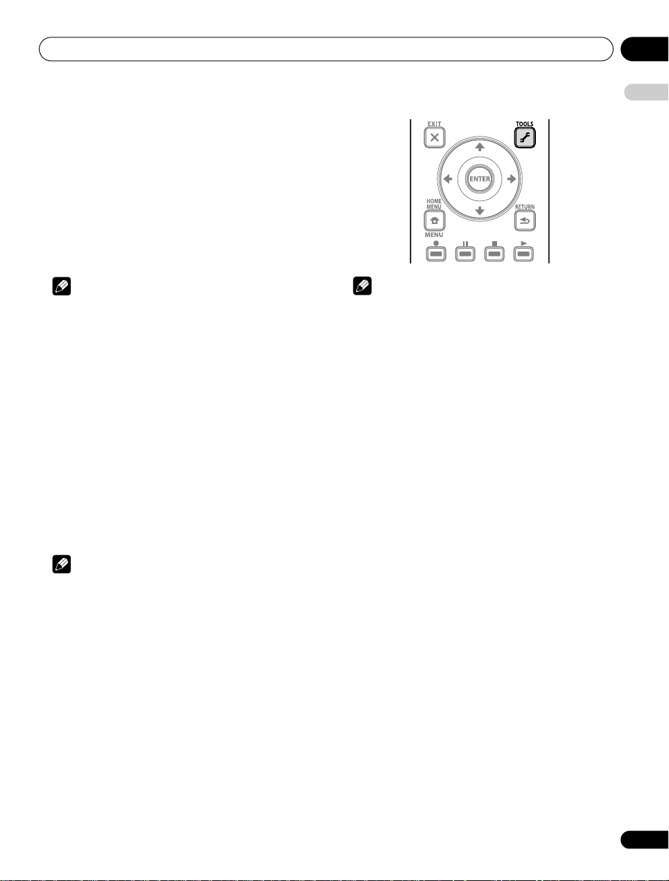
Watching TV 06
Setting your favourite channels
Select up to 10 channels for each screen (up to nine screens). You
can then quickly jump to your favourite channels.
1 Press HOME MENU.
2 Select “Setup” (
3 Select “Favourites Setup” (
4 Select “Channel Mode” (
5 Select “Favourites” (
Select “All” to set all channels to “Favourites”.
6 Press HOME MENU to exit the menu.
/
then ENTER).
/
/
/
).
then ENTER).
).
English
Note
• If there is another screen that follows, a scroll bar appears.
• Pressing ENTER while watching a TV programme also causes
the Favourites List to appear.
• If no channels are registered, “No Favourites List.” appears.
Sorting favourite channels
You can sort favourite channels. To sort the registered channels,
follow the procedure below.
1 Press HOME MENU.
2 Select “Setup” (
3 Select “Favourites Setup” (
4 Select “Sort Favourites” (
5 Select a channel to be shifted (
6 Select a new location (
Sorting is executed.
To sort another channel(s), repeat steps 5 and 6.
7 Press HOME MENU to exit the menu.
Note
• If there is another screen that follows, a scroll bar appears.
/
then ENTER).
/
/
then ENTER).
///
///
then ENTER).
then ENTER).
then ENTER).
Registering favourite channels
Use the TOOLS Menu to register TV channels, external input
sources including PC, and Home Media Gallery content (top menu
screen). To register, follow the procedure below.
1 Press TOOLS.
The TOOLS Menu appears on screen.
2 Select “Favourites Entry” (
3 Select “On” (
The channel you are watching is registered in the Favourites List.
To cancel, use / to select “Off”.
/
/
).
).
Note
• Pressing EXIT, RETURN, or TOOLS again causes the TOOLS
Menu to disappear.
• If the number of channels registered reaches the limit, a
warning screen appears.
• To cancel the above procedure before it finishes, press EXIT or
RETURN.
Editing Input List
You can edit the input channel name. For changing the name,
follow the procedure below.
1 Press HOME MENU.
2 Select “Setup” (
3 Select “Option” (
4 Select “Label Input” (
5 Select an input (
The software keyboard appears.
6 Edit the name.
7 Press HOME MENU to exit the menu.
/
then ENTER).
/
/
/
then ENTER).
then ENTER).
then ENTER).
27
En
Page 28
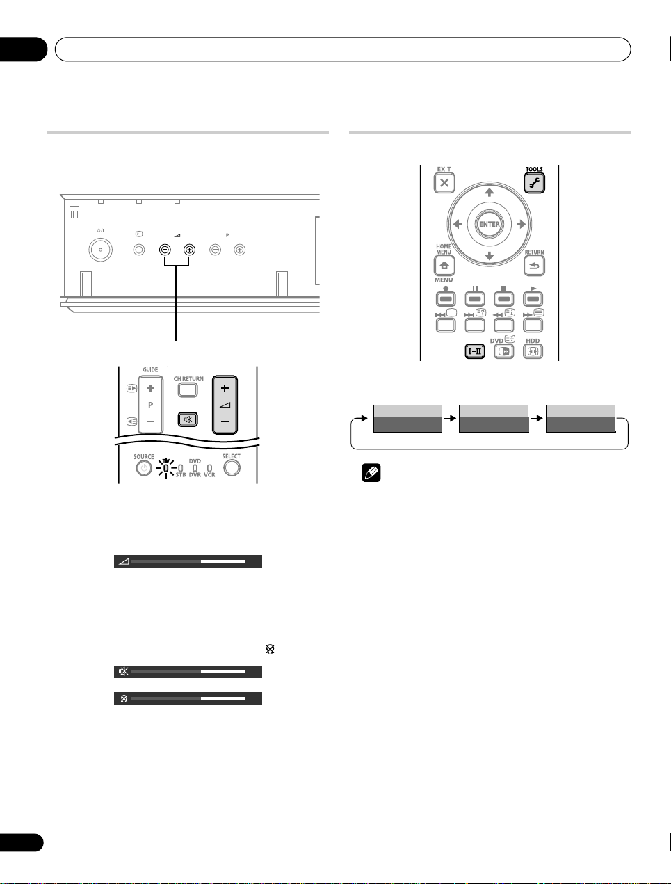
Watching TV06
Media Receiver (front)
VOLUME +/–
37
37
37
Changing the volume and sound
Use the remote control or the control panel of the Media Receiver
to adjust the volume.
ON STANDBY TIMER
STANDBY/ON
Using i +/i
•Press i + to increase the volume.
•Press i – to decrease the volume.
INPUT
VOLUME CHANNEL
– on the remote control unit
Switching the broadcast audio channel
Depending on the broadcast, you can switch the audio channel.
• Press - to change the audio channel.
mode mode MONO mode
I II MONO
Note
•Pressing TOOLS also causes the audio channel mode menu to
appear.
/
• VOLUME +
i +
– on the Media Receiver operates the same as
/
i –.
Using e on the remote control unit
1 Press e to mute the sound.
e appears on the screen. If headphones are used, appears.
2 Press e again or
i +
to restore the sound.
28
En
Page 29
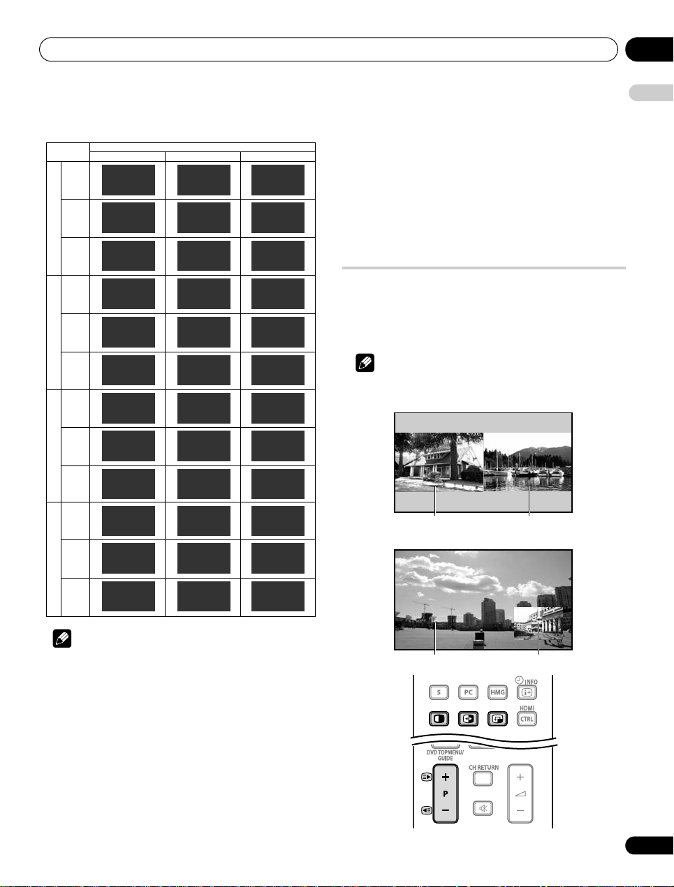
Watching TV 06
2-screen
Picture-in-picture
Main screen Sub screen
Main screen Sub screen
The table below shows the available audio channels by broadcast
audio type.
Setting
A 1
AAA
NICAM STEREO
10:00
A 2
BBB
NICAM II
10:00
A 3
CCC
NICAM MONO
10:00
A 4
DDD
STEREO
10:00
A 5
EEE
DUAL II
10:00
A 6
FFF
MONO
10:00
D 001
GGG
R
10:00
D 002
HHH
STEREO
10:00
D 003
III
MONO
10:00
S 0001
JJJ
R
10:00
S 0002
KKK
STEREO
10:00
S 0003
LLL
MONO
10:00
NICAM BroadcastsA2 BroadcastsDigital Terrestrial Broadcasts
Digital Satellite Broadcasts
Stereo
Bilingual
Monaural
Stereo
Bilingual
Monaural
DualMono
Stereo
Monaural
DualMono
Stereo
Monaural
A 1
AAA
NICAM STEREO
10:00
A 2
BBB
NICAM I
10:00
A 3
CCC
NICAM MONO
10:00
A 4
DDD
STEREO
10:00
A 5
EEE
DUAL I
10:00
A 6
FFF
MONO
10:00
D 001
GGG
L
10:00
D 002
HHH
STEREO
10:00
D 003
III
MONO
10:00
S 0001
JJJ
L
10:00
S 0002
KKK
STEREO
10:00
S 0003
LLL
MONO
10:00
Note
• In each of the sound multiplex mode selected using the -
button, the display changes depending on broadcasting signals
being received.
• Once the MONO mode is selected, the sound remains mono
even if the system receives a stereo broadcast. You must switch
the mode back to or mode if you want to hear stereo sound
again.
• Selecting a sound multiplex mode while the input source is
“INPUT 1” to “INPUT 5” does not change the type of sound. In
this case, sound is determined by the video source.
• For DTV broadcasts, the language you hear immediately after
channel selection depends on the language setting (“Primary
Audio” or “Secondary Audio”) in Selecting languages for audio,
subtitles, and teletext on page 51. In some cases, the selected
language may differ from that displayed on screen.
MONO
AAA
MONO
10:00
BBB
MONO
10:00
CCC
MONO
10:00
DDD
MONO
10:00
EEE
MONO
10:00
FFF
MONO
10:00
D 001
GGG
MONO
10:00
D 002
HHH
MONO
10:00
D 003
MONO
10:00
S 0001
MONO
10:00
S 0002
KKK
MONO
10:00
S 0003
LLL
MONO
10:00
English
Switching an audio component
The TOOLS Menu also allows selecting from up to 32 audio
components.
1 Press TOOLS.
A 1
A 2
A 3
The TOOLS Menu appears on screen.
2 Select “Audio” (
3 Select the desired audio component (
You can switch:
– an audio component between the languages (digital
broadcast only)
– an audio component for the Home Media Gallery (page 73)
/
).
/
).
Using the multiscreen functions
A 4
A 5
A 6
III
JJJ
• Before operating with the remote control unit, make sure to select
the TV mode using its
equipment using the supplied remote control unit
SELECT
button. See
Controlling other
on page 90.
Splitting the screen
Use the following procedure to select 2-screen or picture-in-picture
mode.
Note
• Displaying a split screen for a long period of time, or for shorter
periods of time everyday, may result in image retention.
29
En
Page 30
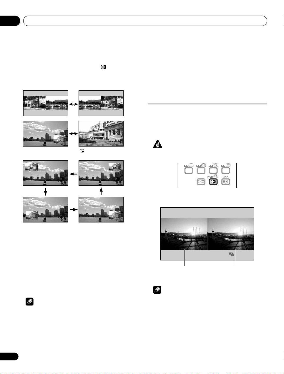
Watching TV06
Normal image
Still image
1 Press c to select the display mode.
Each time you press c, the display mode is switched among 2screen, picture-in-picture, and single-screen.
In 2-screen or picture-in-picture mode, press to switch the
position of the two screens shown.
The left screen (in the 2-screen mode) or the larger screen (in the
picture-in-picture mode) is the active screen which will be indicated
by “z”. The user is allowed to operate picture and sound.
In picture-in-picture mode, press to move the position of the
small screen anticlockwise.
– Analogue TV (digital TV or Home Media Gallery) and external
source (“INPUT 1” to “INPUT 5”, “PC”)
• When you press EXIT, the single-screen mode is restored and
the corresponding menu is displayed.
• When in the 2-screen mode, images displayed on the right
screen may look less fine, depending on the images.
• While in the 2-screen or picture-in-picture mode, the analogue
favourite channel list and the digital channel list are unavailable.
Freezing images
Use the following procedure to capture and freeze one frame from
a moving image that you are watching.
• Before operating with the remote control unit, make sure to select
the TV mode using its
equipment using the supplied remote control unit
Important
• Displaying a static image for a long period of time, or for shorter
periods of time everyday, may result in image retention.
1 Press d.
A still image appears on the right screen while a moving image is
shown on the left screen.
SELECT
button. See
Controlling other
on page 90.
2 To select the desired input source, press the appropriate input
source button.
If watching TV programmes, press P+/P– to change the channel.
Using the TOOLS Menu
You can also select the multiscreen mode from the TOOLS Menu.
1 Press TOOLS.
The TOOLS Menu appears on screen.
2 Select “Split”, “Swap” or “Shift” (
3 Select a mode (
For “Split” mode, select “Off (Single)”, “2-screen” or “P-in-P”.
The selected mode appears in the center of the TOOLS Menu.
Note
• Refer to the TOOLS Menu on page 77.
• The multiscreen function cannot display images from the same
input source at the same time. If you make such an attempt, a
warning message appears.
• The multiscreen function cannot display images from
combinations of two external input sources (“INPUT 1” to
“INPUT 5”, “PC”). It can display images from the following
combinations of input sources.
/
).
/
).
30
En
2 Press d again to cancel the function.
Note
• You cannot freeze the picture when using the 2-screen or
picture-in-picture mode.
• When this function is not available, a warning message
appears.
Page 31

The HOME MENU 07
Chapter 7
The HOME MENU
English
HOME MENU overview
For AV source
HOME MENU
Channel – 26
Favourites – 26
Input – 26
EPG – 53
Home Media
Gallery
HDMI Control – 95
Setup Picture AV Selection 38
Sound Treble 44
Power Control Energy Save 45
Sleep Timer – 63
Option Position 58
Item Page
– 73
Contrast* 39
Brightness* 39
Colour* 39
Tint* 39
Sharpness* 39
Pro Adjust* 40
PureCinema** 40
Sound Control*** 45
OPTIMUM Performance***
Reset 39
Bass 44
Balance 44
Sound Effect 44
Reset 44
AVC 45
No Signal off 46
No Operation off 46
Auto Size 61
Side Mask 61
HDMI Input 69
HDMI Control Setting
Blue LED Dimmer 62
Orbiter 62
Video Pattern 63
Drive Mode 58
Colour System 60
Input Select 59
Game Control Pref 60
Room Light Sensor 62
Screen Protection 63
Label Input 63
System Setup Auto Installation 33
Favourites Setup
* Available when any option other than “OPTIMUM” is selected
from “AV Selection”.
** Access this option through the Pro Adjust menu when any
option other than “OPTIMUM” is selected.
*** Available only when “OPTIMUM” is selected from “AV
Selection”.
Analogue TV Setup 35
Digital Tuner Setup 48
Digital Audio Output 68
SCART Output 66
i/o link.A 72
Password 64
Language 37
Technical Info. 37
Channel Mode 27
Sort Favourites 27
For PC source
HOME MENU Item Page
Channel – 26
45
98
Favourites – 26
Input – 26
EPG – 53
Home Media
Gallery
HDMI Control – 95
Setup Picture AV Selection 38
Sound Treble 44
Power Control Energy Save 45
Sleep Timer – 63
Option Auto Setup 59
Favourites Setup
– 73
Contrast 39
Brightness 39
Red 39
Green 39
Blue 39
Reset 39
Bass 44
Balance 44
Sound Effect 44
Reset 44
AVC 45
Power Management 46
Manual Setup 59
HDMI Input 69
HDMI Control Setting
Orbiter 62
Label Input 63
Channel Mode 27
Sort Favourites 27
98
31
En
Page 32

The HOME MENU07
Using the HOME MENU
The following describes the typical procedure for setting up the
menus. For the actual procedures, see the appropriate pages that
describe individual functions.
DVD HDD
1 Press HOME MENU.
2Press / to select a menu item, and then press ENTER.
3 Repeat step 2 until you access the desired submenu item.
The number of menu layers differs depending on the menu items.
4Press / to select an option (or parameter), and then
press ENTER.
For some menu items, press / instead of /.
5 Press HOME MENU to exit the menu.
Note
• You can return to the upper menu levels by pressing RETURN.
• Before operating with the remote control unit, make sure to
select the TV mode using its SELECT button. See Controlling
other equipment using the supplied remote control unit on
page 90.
32
En
Page 33

Setting up 08
Chapter 8
Setting up
English
Setting up TV channels
This section describes how to automatically search for and set up
TV channels.
Using Auto Installation
When the flat screen TV is switched on for the first time after
purchase, Auto Installation menu appears on screen. For language
and channel selections, follow the steps below.
1 Select “Language” (
2 Select a language (
Language : English
Country : Austria
Terrestrial T uner : Both
Aerial Power : Off
Satellite Tuner : On
Satellite Setup
You can select from among 18 languages; English, German, French,
Italian, Spanish, Dutch, Swedish, Portuguese, Greek, Finnish,
Russian, Turkish, Norwegian, Danish, Czech, Ukrainian,
Hungarian, and Croatian.
3 Select “Country” (
4 Select the country (
5 Select “Terrestrial Tuner” (
6 Select a tuner type (
Use / to select “Digital”, “Analogue”, “Both” (default), or “Off”.
7 Select “Aerial Power” (
This option is available only when you select “Digital” or “Both” in
step 6. Skip steps 7 and 8 when you select other options.
Caution
• When the “Aerial Power” setting is on, directly connect the
aerial to the ANT input terminal at the rear of the flat screen TV.
Connecting any device between the aerial and flat screen TV
may cause damage to the device.
8 Select “On” or “Off” (default)(
9 Select “Satellite Tuner” (
Use / to select “On” (default) or “Off”.
If you select “On”, select “Satellite Setup” then press
to the Satellite Setup screen.
If you select “Off”, the “Satellite Setup” menu dims.
/
/
/
/
/
).
).
).
/
/
).
/
).
).
).
).
/
Start
).
ENTER
to move
10 Select “Start” (
Auto Installation automatically starts. To quit Auto Installation
before it finishes, press RETURN.
Note
• You can start Auto Installation from the HOME MENU after
moving to another country, for example. Follow the steps below
before starting Auto Installation:
1 Press HOME MENU (
2 Select “Setup” (
3 Select “System Setup” (
4 Select “Auto Installation” (
The password entry screen appears. Enter your four-digit password
using buttons 0 to 9. See
If no channel is found, check the antenna connections, and then
retry Auto Installation.
Note
• Channels obtained may vary depending on the installation
environment and weather conditions.
/
then ENTER).
/
/
then ENTER).
Using a password
then ENTER).
/
then ENTER).
/
then ENTER).
on page 64.
Setting up satellite TV channels
manually
You can also set up satellite TV channels manually without using
Auto Installation. For setup details, follow the steps below.
Note
• The “Digital Tuner Setup” option is only available in the DTV/SAT
mode. Press TV/DTV/SAT on the remote control to select the
DTV or SAT mode.
1 Press HOME MENU.
2 Select “Setup” (
3 Select “System Setup” (
4 Select “Digital Tuner Setup” (
5 Select “Installation” (
The password entry screen appears. Enter your four-digit password
using buttons 0 to 9. For the password, see
page 64.
6 Select “Satellite Setup” (
7 Select “Scan Type” (
Use / to select “By Satellite”, “All Frequencies” or “SMATV”.
/
then ENTER).
/
/
/
then ENTER).
/
then ENTER).
/
then ENTER).
then ENTER).
then ENTER).
Using a password
on
33
En
Page 34

Setting up08
Reset
Replace Existing Channels
Add New Channels
Scan T ype : By Satellite
Aerial Select : Single
Satellite Select
Transponder
Signal Check
Satellite : Astra1
LNB Frequency : Universal
LNB Voltage : Off
Level
: 60%
Quality : 80%
T ransponder Type : Manual
Frequency : ---- MHz
Polarization : Horizontal
Symbol Rate : 22000 KS/s
Add
Satellite : Astra1
Transponder : 10000
Level
:
88%
Quality :100%
Note
• Using the “By Satellite” option for channel scanning may fail in
some cases. If this is the case, select “All Frequencies” or
“SMATV”.
• If you access “Satellite Setup” through “Auto Installation”, three
buttons – “Add New Channels”, “Replace Existing Channels”
and “Reset” – are unavailable.
• Selecting “SMATV” (Satellite Master Antenna Television system)
causes your flat screen TV to make an attempt to obtain all
available channels regardless of antenna setting.
• Scanning channels after changing the “Scan Type” option
causes the channel information obtained with the previous
option to disappear.
8 Select “Aerial Select” (
Use / to select “Single”, “DiSEqC 1”, “DiSEqC 2”, “DiSEqC 3”,
“DiSEqC 4”, “Tone Burst 1” or “Tone Burst 2”.
9 Select “Satellite Select” (
10 Select “Satellite” (
Information on the selected satellite appears on screen. Select an
/
/
then ENTER).
).
/
then ENTER).
available satellite from the list.
12 Select “LNB Voltage” (
/
).
Use / to select “On” or “Off” (default).
Select “On” in most cases.
13 Press RETURN then select “Transponder” (
14 Select “Transponder Type” (
Use / to select “All” for all transponders of the selected
satellites (default), “One” for only one transponder, or “Manual” for
/
/
).
).
transponders specified.
15 Select “Frequency” (
The option selected in step 14 appears with available transponders
for the satellite selected on the satellite list in step 10.
Enter a frequency using buttons 0 to 9 (then press
select “Manual” in step 14.
16 Select “Polarization” (
Use / to select “Horizontal” (default) or “Vertical”.
17 Select “Symbol Rate” (
Use / to select “22000” (default), “27500” or use buttons 0 to 9
(then press
ENTER
/
).
/
).
/
).
) to enter a symbol rate.
ENTER
) if you
Note
• “Polarization” and “Symbol Rate” options are only available if
you select “Manual” from “Transponder Type” in step 14.
18 Press RETURN then select “Signal Check” (
Use / to select the desired satellites from the satellite list or
/
then ENTER).
transponders for the selected satellites.
Units for LNB Frequency is MHz.
This option is available only if you select “By Satellite” in step 7.
Select “New 1” through “New 5” then press and hold
display the software keyboard.
11 Select “LNB Frequency” (
Use / to select “Universal” (having two LNB frequencies - 9750/
10600, default) or use buttons 0 to 9 (then press
frequency if you select “---”.
This option is available only when you select “All Frequencies” or
“By Satellite” in step 7.
34
En
/
).
ENTER
ENTER
to
) to enter a
Note
• If you access “Signal Check” through “Auto Installation”, the
button “Add” is unavailable (see page 49).
• Units for Transponder is MHz.
To search and register new channels, select “Add New Channels”
(see page 49).
Page 35

Setting up 08
Manual Adjust
Label
Sort
To replace registered channels with new channels, select “Replace
Existing Channels” (see page 49).
“Reset” restores all satellite settings to factory default values.
19 Press HOME MENU to exit the menu.
Setting up analogue TV channels
manually
Use the Manual Adjust function to set up analogue TV channels
manually.
1 Press HOME MENU.
2 Select “Setup” (
3 Select “System Setup” (
4 Select “Analogue TV Setup” (
The password entry screen appears. Enter your four-digit password
using buttons 0 to 9. For the password, see Using a password on
page 64.
5 Select “Manual Adjust” (
6 Select “Programme Entry” (
7 Select a programme number (
You can select 1 through 99.
8 Select “Search” (
9 Enter a frequency using buttons 0 to 9, then ENTER.
You can also press / to enter a frequency.
10 Select “System” (
11 Select a sound system (
You can select from among “B/G”, “D/K”, “I”, “L”, and “ L’ ”.
12 Select “Colour System” (
13 Select a colour system (
You can select from among “Auto”, “PAL”, “SECAM”, and “4.43NTSC”.
14 Select “Store” (
15 Select “Yes” or “No” (
Item Description
Yes You can select the channel using P+/P–
No You cannot select the channel using P+/P–
16 Press HOME MENU to exit the menu.
Alternatively, to set up for another channel, repeat steps 7 to 15.
/
/
/
/
).
then ENTER).
/
then ENTER).
/
/
then ENTER).
/
/
).
).
/
).
/
).
/
).
/
).
then ENTER).
).
).
Note
• The above procedure transfers and sets the selected channel
information to the connected recording equipment such as a
VCR or DVD/HDD recorder (DVR).
• Manual Adjust also allows you to make selections for “Tuner
NR”, “Channel Lock”, and “Decoder”. See Reducing video noise,
Setting Channel Lock, and Selecting a decoder input terminal.
Reducing video noise
For the individual channels, you can specify whether the flat screen
TV should reduce video noise depending on the levels of
broadcasting signals.
1 Repeat steps 1 to 5 provided for
channels manually
2 Select “Tuner NR” (
3 Select “On” (
4 Press HOME MENU to exit the menu.
Note
• This function may not achieve a satisfactory result, depending on
the conditions of broadcasting signals.
• When using a decoder with a decoder terminal selected, this
function may fail to achieve a good result.
• The factory default is “On”.
.
/
/
).
Setting up analogue TV
).
Setting Channel Lock
Channel Lock inhibits selected TV channels from being tuned and
watched.
1 Repeat steps 1 to 7 provided for
channels manually
After selecting a channel (using Programme Entry), perform the
following steps:
2 Select “Channel Lock” (
3 Select “Block” (
The selection is switched between “View” (factory default) and
“Block”.
4 Press HOME MENU to exit the menu.
.
/
/
).
Setting up analogue TV
).
English
35
En
Page 36

Setting up08
Programme Entry : 1
Label : 12345678
KIDS
1234567890
ABCDEFGH I J
KLMNOPQRST
UVWXYZ , . : ;
&'( )+- * /_@
OK Cancel
Caps
Space
Delete
Label
Selecting a decoder input terminal
If you have connected a decoder, select a decoder input terminal
(INPUT 1).
1 Press HOME MENU.
2 Select “Setup” (
3 Select “System Setup” (
4 Select “Analogue TV Setup” (
The password entry screen appears. Enter your four-digit password
using buttons 0 to 9. For the password, see Using a password on
page 64.
5 Select “Manual Adjust” (
6 Select “Programme Entry” (
7 Select a programme number (
/
then ENTER).
/
then ENTER).
/
/
then ENTER).
/
then ENTER).
).
/
).
You can select 1 through 99.
After selecting a channel (using Programme Entry), perform the
following steps:
8 Select “Decoder” (
9 Select “INPUT 1” (
/
/
).
).
10 Press HOME MENU to exit the menu.
Note
• With “Off” (factory default) selected, you cannot watch any
images from the decoder.
• While watching DTV, no image is output to the decoder.
Labeling TV channels
You can name TV channels that you have set up, using up to eight
characters. This may help you easily identify the channels during
selections.
1 Repeat steps 1 to 4 provided for
terminal
.
2 Select “Label” (
/
then ENTER).
3 Select “Programme Entry” (
4 Select a programme number (
You can select 1 through 99.
Selecting a decoder input
/
).
/
).
6 Select the first character (
///
then ENTER).
The cursor moves to the second character.
7 Repeat step 6 to enter up to eight characters.
To correct entered characters, select [] or [] on the screen, and
then press ENTER. The cursor moves to the preceding or
subsequent character.
To delete the current character, select [Delete] on the screen, and
then press ENTER.
To put a space for the current character, select [Space] on the
screen, and then press ENTER.
To toggle between upper case and lower case, select [Caps] on the
screen, and then press ENTER.
8 To complete the name entry, press
[OK] on the screen, and then press ENTER.
/
or
/
to select
9 Press HOME MENU to exit the menu.
Note
• The above procedure transfers and sets the selected channel
information to the connected recording equipment such as a
VCR or DVD/HDD recorder (DVR).
36
En
5 Select “Label” (
The name entry screen appears.
/
then ENTER).
Page 37

Setting up 08
01 AAA
02 BBB
03 CCC
04 DDD
05 EEE
06 FFF
07 GGG
08 HHH
1/4
TELEVISION
Sort
09 III
10 JJJ
11 KKK
12 LLL
13 MMM
14 NNN
15 OOO
16 PPP
17 QQQ
18 RRR
19 SSS
20 TTT
21 UUU
22 VVV
23 WWW
24 XXX
25 YYY
Menu : English
Teletext : West Europe
Sorting preset TV channels
Language setting
English
Use the following procedure to change the sequence of the preset
TV programmes.
1 Repeat steps 1 to 4 provided for
terminal
.
2 Select “Sort” (
The sort screen appears.
/
then ENTER).
3 Select a channel to be shifted (
4 Select a new location (
Sorting is executed.
///
Selecting a decoder input
///
then ENTER).
then ENTER).
5 Press HOME MENU to exit the menu.
Note
• To change a page on the Sort screen in step 2, select the arrow
icon on the screen with / then press ENTER.
• The above procedure transfers and sets only the shifted c hannel
information to recording equipment such as a VCR or DVD/
HDD recorder (DVR).
You can select the language to be used for on-screen display such
as menus and instructions, from among 18 languages; English,
German, French, Italian, Spanish, Dutch, Swedish, Portuguese,
Greek, Finnish, Russian, Turkish, Norwegian, Danish, Czech,
Ukrainian, Hungarian, and Croatian.
For the language to be used in the Teletext mode, you can select
from among West Europe, East Europe, Greece/Turkey, Cyrillic, and
Arabia.
1 Repeat steps 1 to 3 provided for
.
terminal
2 Select “Language” (
3 Select “Menu” (
4 Select a language (
5 Select “Teletext” (
6 Select a language (
/
/
/
).
/
).
/
Selecting a decoder input
then ENTER).
).
).
7 Press HOME MENU to exit the menu.
Checking software/hardware version
To access the version information, follow the procedure below.
1 Repeat steps 1 to 3 provided for
terminal
.
2 Select “Technical Info.” on page 2 of the menu (
ENTER).
3 Press HOME MENU to exit the menu.
Selecting a decoder input
/
then
37
En
Page 38

Setting up08
OPTIMUM
STANDARD
DYNAMIC
MOVIE
PURE
GAME
USER
AV Selection
AV Selection
Select from the seven viewing options, depending on the current
environment (e.g., room brightness), the type of the current TV
programme, or the type of images input from external equipment.
Your flat screen TV has been adjusted to provide optimum sound
quality for each AV Selection option. However, you can adjust it to
your preference.
1 Press HOME MENU.
2 Select “Setup” (
3 Select “Picture” (
4 Select “AV Selection” (
5 Select the desired option (
For AV source
/
then ENTER).
/
then ENTER).
/
then ENTER).
/
then ENTER).
For AV source
Item Description
OPTIMUM Automatically adjusts the brightness of the image
STANDARD
DYNAMIC Sharp imaging with the maximum contrast.
MOVIE Optimized for movies.
PURE Reflects input signals as faithfully as possible for
GAME Lowers image brightness for easier viewing.
USER Allows the user to customize settings as desired.
to the optimum level in accordance with the
brightness level of the viewing area.
This setting is shared by both the external inputs
and TV input sources.
For a highly defined image in a normally bright
.
room
This setting is shared by both the external inputs
and TV input sources.
Note that this mode does not allow manual image
quality adjustment.
This setting is shared by both the external inputs
and TV input sources.
This setting is shared by both the external inputs
and TV input sources.
checking image materials, for example.
This setting is shared by both the external inputs
and TV input sources.
This setting is shared by both the external inputs
and TV input sources.
You can set the mode for each input source.
38
En
For PC source
Item Description
STANDARD
USER Allows the user to customize setting as desired.
6 Press HOME MENU to exit the menu.
• As “OPTIMUM” automatically optimizes image quality, the
process in which image settings such as brightness and tint
gradually change may be seen on the screen. This is not a
malfunction.
For a highly defined image in a normally bright room
You can set the mode for each input source.
Note
Page 39

Setting up 08
AV Selection : STANDARD
Contrast : 40
Brightness : 0
Colour : 0
Tint : 0
Sharpness : 0
Pro Adjust
Reset
Picture
AV Selection : OPTIMUM
PureCinema
Sound Control : Off
OPTIMUM Performance
Reset
Picture
AV Selection : STANDARD
Contrast : 40
Brightness : 0
Red : 0
Green : 0
Blue : 0
Reset
Picture
Contrast
32
Basic picture adjustments
Adjust the picture to your preference for the chosen AV Selection
option (except DYNAMIC).
1 Repeat steps 1 to 3 provided for
2 Select an item to be adjusted (
If you select “OPTIMUM” for “AV Selection”, the following submenu
appears on screen.
AV Selection
/
then ENTER).
.
For AV source
Item button button
Contrast For less contrast For more contrast
Brightness For less brightness For more brightness
Colour For less colour intensity For more colour
intensity
Tint Skin tones become
purplish
Skin tones become
greenish
Sharpness For less sharpness For more sharpness
For PC source
Item button button
Contrast For less contrast For more contrast
Brightness For less brightness For more brightness
Red For weaker red For stronger red
Green For weaker green For stronger green
Blue For weaker blue For stronger blue
English
For PC source, the following screen appears;
3 Select the desired level for AV Selection options other than
“OPTIMUM” (
When the bar is in display, you can also change the item to be
adjusted, by pressing /.
4 Press HOME MENU to exit the menu.
/
).
Note
• To perform advanced picture adjustments, select “Pro Adjust”
in step 2 and then press ENTER. For the subsequent procedures
see Advanced picture adjustments on page 40.
• To restore the factory defaults for all items, press / to select
“Reset” in step 2, and then press ENTER. A confirmation screen
appears. Press / to select “Yes”, and then press ENTER.
• You may experience a sudden change in the image p osition and
screen brightness when you open the “Picture” menu.
• Pressing TOOLS also causes the “AV Selection” menu to
appear.
• If you have selected “DYNAMIC”, you cannot select “Contrast”,
“Brightness”, “Colour”, “Tint”, “Sharpness”, “Pro Adjust”, and
“Reset”; these menu items are dimmed.
• Selecting “OPTIMUM” causes optional menus to appear:
“Sound Control” and “OPTIMUM Performance” (page 45).
• When “OPTIMUM” is selected, image s are reproduced based on
the information collected at the Room Light Sensor, as well as
the colour sensor (when in use).
39
En
Page 40

Setting up08
Advanced picture adjustments
The flat screen TV provides various advanced functions for
optimizing the picture quality. For details on these functions, see
the tables.
Using PureCinema
1 Press HOME MENU.
2 Select “Setup” (
3 Select “Picture” (
4 Select “Pro Adjust” (
5 Select “PureCinema” (
6 Select “Film Mode” or “Text Optimisation” (
7 Select the desired parameter (
For the selectable parameters, see the table.
PureCinema
Automatically detects a film-based source (originally encoded at
24 frames/second), analyses it, then recreates each still film frame
for high-definition picture quality
Film Mode Off Deactivates the PureCinema
Text
Optimisation
8 Press HOME MENU to exit the menu.
/
then ENTER).
/
then ENTER).
/
then ENTER).
/
then ENTER).
/
then ENTER).
/
then ENTER).
Standard Produces smooth and vivid moving
Smooth Makes movie images smoother.
Advance Produces smooth and quality
Off Deactivates Text Optimisation
On Improves subtitle display quality
images (film specific) by
automatically detecting recorded
image information when
displaying movie images such as
movie programmes on TV
(interlaced)
This mode for users who prefer
smoother images rather than filmlike images.
moving images (as shown on
theatre screens) by converting to
appropriate panel drive frequency
when displaying DVD or BD
images (e.g., movies)
Using Intelligent Mode
1 Repeat steps 1 to 4 provided for
2 Select “Intelligent Mode” (
3 Select the desired parameter (
Intelligent Mode
Performs such compensation that results in the optimum colour
tones and brightness for images
Selections Off Deactivates Intelligent Mode
Mode 1 Compensates for more effective
Mode 2 Compensates for appropriate
4 Press HOME MENU to exit the menu.
Note
• As this function automatically optimizes image quality, the process in
which image settings such as brightness and tint gradually change
may be seen on the screen. This is not a malfunction.
Using PureCinema
/
then ENTER).
/
then ENTER).
picture adjustment for general
viewing
picture adjustment, especially for
private content such as home
video
.
Using the Picture Detail
1 Repeat steps 1 to 4 provided for
2 Select “Picture Detail” (
3 Select an item to be adjusted (
You can select “DRE Picture”, “Black Level”, “ACL”, “Enhancer
Mode” or “Gamma”.
4 Select the desired parameter (
DRE (Dynamic Range Expander) Picture
Emphasizes the contrast on images so that the difference between
brightness and darkness becomes more distinct
Selections Off Deactivates DRE Picture
High Enhanced DRE Picture
Mid Standard DRE Picture
Low Moderate DRE Picture
/
Using PureCinema
then ENTER).
/
then ENTER).
/
then ENTER).
.
Note
• This function may not work properly depending on the input
signal.
• When you select “On” for “Game Control Pref” on the “Option”
menu, the “PureCinema” setting is disabled.
40
En
Black Level
Emphasizes dark portion on images so that the difference
between brightness and darkness becomes more distinct
Selections Off Deactivates Black Level
On Activates Black Level
Page 41

Setting up 08
ACL (Automatic Contrast Limiter)
Performs such compensation that results in the optimum contrast
characteristics for images
Selections Off Deactivates ACL
On Activates ACL
Enhancer Mode
Selects processing of the image’s high frequency (detailed) areas
to find the right balance between preserving picture detail and
eliminating unwanted noise
Selections 1 Selects Hard (SHARPNESS) image
2 Selects Natural (SHARPNESS) image
3 Selects Soft (SHARPNESS) image
Gamma
Adjusts the gamma characteristics (image gradation
characteristics) to find the right balance between contrast and
maintaining dark details
Selections 1 Delivers uniformly contrast-rich images
2 Delivers a well balanced image, applying
3 Delivers an overall slightly brighter image,
5 Press HOME MENU to exit the menu.
delicate in-picture contrast enhancement
revealing more gradation details
Using Colour Temp
1 Press HOME MENU.
2 Select “Setup” (
3 Select “Picture” (
4 Select “Pro Adjust” (
5 Select “Colour Detail” (
6 Select “Colour Temp” (
7 Select the desired parameter (
Colour Temp
Adjusts the colour temperature, resulting in a better white balance
Selections High Cool white tone
/
then ENTER).
/
then ENTER).
/
then ENTER).
/
then ENTER).
/
then ENTER).
/
then ENTER).
Mid-High Intermediate tone between High and Mid
Mid Natural tone
Mid-Low Intermediate tone between Mid and Low
Low Warm white tone
Manual Colour temperature adjusted to your
preference
You may rather want to perform fine adjustment. To do this, select
“Manual” first and then press and hold ENTER for more than three
seconds. The manual adjustment screen appears. Then go to step
8.
8 Select an item to be adjusted (
9 Select the desired level (
Item button button
R High Fine adjustment
for bright portions
G High For weaker green For stronger
B High For weaker blue For stronger blue
R Low Fine adjustment
for dark portions
G Low For weaker green For stronger
B Low For weaker blue For stronger blue
To perform adjustment for another item, press RETURN, and then
repeat steps 8 and 9.
You may press / to immediately change an item to be adjusted.
10 Press HOME MENU to exit the menu.
/
then ENTER).
/
).
For weaker red For stronger red
green
For weaker red For stronger red
green
Using CTI and Colour Space
1 Repeat steps 1 to 5 provided for
2 Select “CTI” or “Colour Space” (
3 Select the desired parameter (
CTI
Provides images with clearer colour contours. The CTI stands for
Colour Transient Improvement.
Selections Off Deactivates CTI
On Activates CTI
Colour Space
Changes the colour reproduction space
Selections 1 Optimized for vivid, vibrant colour
2 Standard colour reproduction
4 Press HOME MENU to exit the menu.
Using Colour Temp
/
then ENTER).
/
then ENTER).
reproduction
.
English
41
En
Page 42

Setting up08
R0
Y0
G0
C0
B0
M0
Colour Management
Using Colour Management
1 Repeat steps 1 to 5 provided for
2 Select “Colour Management” (
3 Select an item to be adjusted (
4 Select the desired level (
Item button button
R Closer to magenta Closer to yellow
Y Closer to red Closer to green
G Closer to yellow Closer to cyan
C Closer to green Closer to blue
B Closer to cyan Closer to magenta
M Closer to blue Closer to red
To perform adjustment for another item, press RETURN, and then
repeat steps 3 and 4.
You may press / to immediately change an item to be adjusted.
5 Press HOME MENU to exit the menu.
/
/
/
).
Using Colour Temp
then ENTER).
then ENTER).
.
Eliminating noise from images
1 Repeat steps 1 to 4 provided for
2 Select “Noise Reduction” (
3 Select an item to be adjusted (
You can select “3DNR”, “Field NR”, “Block NR” or “Mosquito NR”.
4 Select the desired parameter (
3DNR
Eliminates video noise for clear, crisp images. 3DNR stands for 3dimensional Noise Reduction.
Selections Off Deactivates 3DNR
High Enhanced 3DNR
Mid Standard 3DNR
Low Moderate 3DNR
Field NR
Removes glimmer for more natural images
Selections Off Deactivates Field NR
High Enhanced Field NR
Mid Standard Field NR
Low Moderate Field NR
Block NR
Reduces noise such as blocks appearing in digitally compressed
sources on DVD and in digital broadcasting
Selections Off Deactivates Block NR
On Activates Block NR
Using Colour Temp
/
then ENTER).
/
then ENTER).
/
then ENTER).
.
42
En
Mosquito NR
Reduces noise in contoured portions appearing in digitally
compressed sources on DVD and in digital broadcasting
Selections Off Deactivates Mosquito NR
On Activates Mosquito NR
5 Press HOME MENU to exit the menu.
Page 43

Setting up 08
Using the 3DYC and I-P Mode
1 Repeat steps 1 to 4 provided for
2 Select “Others” (
3 Select “3DYC” or “I-P Mode” (
4 Select the desired parameter (
3DYC
Optimizes characteristics for separating brightness signals and
colour signals. This works for both video and still images.
Selections Off Deactivates 3DYC
Note
• For the 3DYC, the individual parameters are selectable only
when:
– You have selected “INPUT 1”, “INPUT 2” or “INPUT 3” as the
input source and “Video” as the input signal type (see Selecting
an input signal type on page 59); or
– You have selected “INPUT 5” as the input source or you have
selected the analogue tuner.
• The 3DYC setting is ineffective when SECAM, PAL60, or
4.43NTSC signals are input.
I-P Mode
Performs optimum conversion from interlace signals to
progressive signals. This works for both video and still images.
Selections 1 Primarily for images with fast
Note
• The I-P Mode setting is disabled if you use an external input
source and select “On” for “Game Control Pref” on the “Option”
menu.
• For the I-P Mode, the individual parameters are not selectable
for the following input signals: 480p, 576p, 720p, 1080p.
5 Press HOME MENU to exit the menu.
/
then ENTER).
High Enhanced 3DYC
Mid Standard 3DYC
Low Moderate 3DYC
2 Well balanced setting for both
3 Primarily for images with little or
Using Colour Temp
/
then ENTER).
/
then ENTER).
motion
moving and still images
no motion
.
Comparing picture adjustments on the
screen
During picture adjustments, you can quickly refer to the image
previously set in the same parameter, allowing you to easily
compare and select the preferred image quality.
1 Repeat steps 1 to 3 provided for
2 Select an item to be adjusted
3 While performing adjustment, press TOOLS on the remote
control unit.
“Before” displays and the image adjusted last time appears for
comparison.
Before
4 Press the button again to return to the newly adjusted image.
Each press of the button toggles between “Before” and “After”.
5 Repeat steps 2 and 4 for other parameters.
6 Press HOME MENU to exit the menu.
Caution
• If you exit the menu by pressing
performed for 60 seconds, all the parameter settings displayed last
are stored in memory.
• If you want to exit the menu without performing the adjustments (or
leaving the settings disabled) on the “After” screen, switch to
“Before” and then exit.
Note
• You cannot adjust any item while on the “Before” screen. A
warning message appears.
• When you switch to another parameter, make sure to change
the display from “Before” to “After” first, otherwise you cannot
select “Before”. A warning message appears if you don’t.
• If you exit the selection from the “Before” screen, the previous
entry is stored in the memory and the TOOLS button no longer
works.
• If you exit the selection from the “After” screen, the new entry is
stored in the memory and the button no longer works.
• If you move and change the “AV Selection” parameter, the new
entry in the current parameter is stored in the memory and the
button continues to work.
• You cannot compare images between different parameters on
the “AV Selection” menu (“STANDARD” and “MOVIE”, for
example).
• When you select this function, “Intelligent Mode” for “Pro
Adjust” on the “Picture” menu, and “Room Light Sensor” on the
“Option” menu are set to off and image quality returns to default
settings.
• This function is not selectable:
– when “OPTIMUM” is selected for “AV Selection”.
– when you select “AV Selection”,
– when you select “Yes” or “No” on the confirmation screen for
“Reset” from the “Picture” menu or
– when you select a menu from the PC source
Using Colour Temp
(/
then ENTER).
HOME MENU
.
or no operation is
English
43
En
Page 44

Setting up08
Treble : 0
Bass : 0
Balance : 0
Sound Effect
Reset
AVC : Off
Sound adjustments
You can adjust the sound quality to your preference with the
following settings.
Adjust the sound to your preference for the chosen AV Selection
option. See AV Selection on page 38.
1 Press HOME MENU.
2 Select “Setup” (
3 Select “Sound” (
4 Select an item to be adjusted (
5 Select the desired level (
Item button button
Treble For weaker treble For stronger treble
Bass For weaker bass For stronger bass
Balance Shifts the audio balance
6 Press HOME MENU to exit the menu.
Note
• You can adjust the sound for listening with headphones.
• To restore the factory defaults for the “Treble”, “Bass”, “Balance”
and “Sound Effect” options, press / to select “Reset” in step
4, and then press ENTER. A confirmation screen appears. Press
/ to select “Yes”, and then press ENTER.
• You cannot restore the factory default for “AVC”.
•Pressing TOOLS while using Home Media Gallery functions
also causes the “Sound” menu to appear.
44
En
/
/
to the left
then ENTER).
then ENTER).
/
/
).
).
Shifts the audio balance
to the right
Sound Effect
You can select from SRS FOCUS, SRS, SRS TruBass and SRS
Definition.
1 Repeat steps 1 to 3 provided for
2 Select “Sound Effect” (
3 Select “SRS FOCUS”, “SRS”, “SRS TruBass” or “SRS Definition“
(
/
).
4 Select the desired parameter (
SRS FOCUS
Moves sound source direction vertically and makes sound and
voice clearly audible
Selections Off Deactivates SRS FOCUS
SRS
Effortlessly produces a three-dimensional sound field
Selections Off Deactivates SRS
SRS TruBass
Produces a clear, rich bass tone
Selections Off Deactivates SRS TruBass
SRS Definition
Improves midrange quality and clarifies voice and instrument
sound
Selections Off Deactivates SRS Definition
5 Press HOME MENU to exit the menu.
TM
Low Moderate SRS FOCUS
Mid Standard SRS FOCUS
High Enhanced SRS FOCUS
®
Low Moderate SRS
Mid Standard SRS
High Enhanced SRS
®
Low Moderate SRS TruBass
Mid Standard SRS TruBass
High Enhanced SRS TruBass
®
Low Moderate SRS Definition
Mid Standard SRS Definition
High Enhanced SRS Definition
/
Sound adjustments
then ENTER).
/
).
.
Page 45

Setting up 08
Note
TM
• (SRS WOW HD
FOCUS, SRS, SRS TruBass and SRS Definition
• You can adjust the sound effect for listening with headphones.
• The effect of this function differs depending on signals.
) denotes a status where SRS
are on.
OPTIMUM Performance
Select this option when “OPTIMUM” is selected in the “AV
Selection” menu for optimum picture quality. You can easily
recognize the status of adjustments with an on-screen bar graph
monitor. For selection, follow the procedure below.
1 Repeat steps 1 to 6 provided for
2 Select “OPTIMUM Performance” (
The on-screen bar graph monitor appears.
Using Sound Control
/
then ENTER).
.
English
Using AVC (Auto Volume Control)
Reduces sudden volume change and compensates source sound
level. To select this option, follow the procedure below.
1 Repeat steps 1 to 3 provided for
2 Select “AVC” (
3 Select “On” (
4 Press HOME MENU to exit the menu.
Note
• To cancel this option, select “Off” in step 3.
/
/
).
).
Sound adjustments
.
Using Sound Control
Select this option when “OPTIMUM” is selected in the “AV
Selection” menu for optimum audio levels adjusted to the picture.
1 Press HOME MENU.
2 Select “Setup” (
3 Select “Picture” (
4 Select “AV Selection” (
5 Select “OPTIMUM” (
6 Press RETURN to return to the immediately previous menu.
7 Select “Sound Control” (
8 Select “On” (
9 Press HOME MENU to exit the menu.
Note
• If “Sound Control” is set to “On” in the “Picture” menu, the
“Sound” menu options are unavailable except “AVC”.
• This function is unavailable if any option other than “OPTIMUM”
is selected.
/
/
/
then ENTER).
then ENTER).
then ENTER).
/
then ENTER).
/
then ENTER).
/
then ENTER).
Note
• OPTIMUM Performance compares the picture and sound
quality between “Off” (unadjusted) and “On” (adjusted) using
TOOLS
the
• This function is unavailable if any option other than “OPTIMUM”
is selected.
• When “OPTIMUM” is selected, press and hold p to display the
OPTIMUM Performance. Pressing p while displaying Teletext
pages or subtitles does not cause OPTIMUM Performance to
appear.
• To cancel the OPTIMUM Performance, press EXIT.
• The OPTIMUM Performance is unavailable for a PC image.
button.
Power Control
Power Control provides convenient functions for power saving.
Energy Save
You may use one of the three Energy Save modes to save power
consumption.
1 Press HOME MENU.
2 Select “Setup” (
3 Select “Power Control” (
4 Select “Energy Save” (
5 Select “Mode1”, “Mode2” or “Off” (
Energy Save
Selections Off Provides normally bright pictures
6 Press HOME MENU to exit the menu.
/
then ENTER).
/
then ENTER).
/
then ENTER).
/
then ENTER).
Mode1 Consumes less power than “Off”
Mode2 Consumes less power than
mode
“Mode1”
45
En
Page 46

Setting up08
Note
• When you change the Energy Save mode, you may notice a
change in the panel sound. This is normal.
• The Energy Save function can maintain efficiency of the screen
for a long period of time. Setting the Energy Save function to
“Mode1” is recommended in order to maintain the efficiency of
the screen for a long period of time.
No Signal off (AV source only)
The system will be automatically placed into the standby mode if no
signal is received for 15 minutes.
1 Repeat steps 1 to 3 provided for
2 Select “No Signal off” (
3 Select “Enable” (
No Signal off
Selections Disable
4 Press HOME MENU to exit the menu.
• Five minutes before the system is placed into the standby mode,
a message appears every minute.
• The system may not be placed into the standby mode when
noise signals are present at the Media Receiver after a TV
programme finishes.
(default)
Enable Places the system into the standby
Note
/
then ENTER).
/
Energy Save
then ENTER).
Does not place the system into the
standby mode
mode if no signal is received for 15
minutes
.
No Operation off (AV source only)
The system will be automatically placed into the standby mode
when no operation is performed for three hours.
1 Repeat steps 1 to 3 provided for
2 Select “No Operation off” (
3 Select “Enable” (
No Operation off
Selections Disable
4 Press HOME MENU to exit the menu.
/
then ENTER).
(default)
Enable Places the system into the standby
Energy Save
/
then ENTER).
Does not place the system into the
standby mode
mode if no operation is performed
for three hours
.
Note
• Five minutes before the system is placed into the standby mode,
a message appears every minute.
Power Management (PC source only)
The system will be automatically placed into the standby mode
when no signal is received from the personal computer.
1 Repeat steps 1 to 3 provided for
2 Select “Power Management”
3 Select “Mode1” or “Mode2”
Item Description
Off (default) No power management
Mode1 • Places the system into the standby mode when
no signal is received from the personal computer
for eight minutes.
• Even when you start using the computer and a
signal is received again, the system stays off.
• The system is switched on again by pressing
STANDBY/ON on the Media Receiver or
the remote control unit.
Mode2 • Places the system into the standby mode when
no signal is received from the personal computer
for eight seconds.
• When you start using the computer and a signal
is input again, the system is switched on.
• The system is switched on again by pressing
STANDBY/ON on the Media Receiver or
the remote control unit.
4 Press HOME MENU to exit the menu.
Note
• This function is not selectable when the PC is connected to the
HDMI terminal.
Energy Save
(/
(/
.
then ENTER).
then ENTER).
a
on
a
on
Picture Off
To save energy and extend the life of your display, have the screen
turn Off. To deactivate the screen, follow the steps below.
1 Press TOOLS.
The TOOLS Menu appears on screen.
2 Select “Picture Off” from the TOOLS Menu.
3 Press ENTER.
The screen display turns Off.
To restore the screen display, press any buttons other than i+/
i– and e.
46
En
Note
• The Picture Off setting is not memorized by the system.
Page 47

Enjoying DTV/SAT broadcasts 09
XXXX 001
XXXX 002
XXXX 003
XXXX 010
XXXX 015
XXXX 050
XXXX 051
XXXX 120
XXXX 220
XXXX 221
1/2
Digital
(DTV menu screen)
(Satellite menu screen)
Chapter 9
Enjoying DTV/SAT broadcasts
English
Watching DTV/SAT programmes
Digital Terrestrial/Satellite TV (DTV/SAT) not only replaces the
conventional analogue TV channels, but also provides more
channels, clearer picture quality, and various types of useful
information. It also provides various features, including subtitling
and multiple audio tracks.
Caution
• The compatibility of this product with digital terrestrial and
satellite services has been fixed - details described in the
product specifications - at the time of its introduction.
Note
• When executing Auto Installation (page 33), make sure to select
“On” for “Satellite Tuner” and “Digital” or “Both” for “Terrestrial
Tuner”.
• Selecting the DTV or SAT mode when no channels yet searched
will only display “Digital Tuner Setup” screen with only the item
“Installation” selectable. To watch a digital satellite TV
programme, select “On” for “Satellite Tuner” on the Auto
Installation menu.
• While in the DTV or SAT mode, press m to display the Teletext
screen (except in UK).
Changing channels
1 Press HOME MENU.
2 Select “Channel” (
The Digital Channel List appears on screen when viewing a digital
terrestrial channel, while the Satellite Channel List appears when
viewing a digital satellite channel. Pressing or causes the
channel list to cycle through Satellite Channel List, Favourites List,
Input List, Analogue TV List and Digital Channel List.
/
then ENTER).
Using the Channel List search
You can use the Channel List search function while showing the
Digital or Satellite TV Channel List. To use this option, follow the
procedure below.
1 Press TOOLS.
The search screen appears.
2 Select “Service Type”, “HD/SD” or “List Name” for Digital
Channel List (
For Satellite Channel List, select “Service Type”, “Satellite”, “HD/
SD”, “Scramble”, “Initial” or “List Name”.
3 Select the desired parameter (
• “All”, “TV”, “Radio” or “Data” for “Service Type”
• “All” or satellite names scanned for “Satellite”
• “All”, “HD” or “SD” for “HD/SD”
• “All”, “Scramble” or “Non Scramble” for “Scramble”
• “All”, an initial (A to Z), or “Others” for “Initial” (Initial letter of a
• “All”, a channel name obtained from broadcast, or “Others” for
4 Select “Start” (
Searching starts and the search results appear.
“No Channels Found” appears if there are no channels specified in step 3.
5 Select a channel (
You can also select channels by pressing buttons 0 to 9 or P+/P– on
the remote control unit.
/
).
channel name)
“List Name”
/
then ENTER).
Service Type : All
Satellite : All
HD/SD : All
Scramble : All
Initial : All
List Name : All
/
Search
then
///
Start
ENTER
).
).
Note
• While in DTV mode, press 001 to access channel 1 (one-digit
channel) quickly. You can, however, select the channel 1 by
pressing 01 or 1 but have to wait for two seconds since the last
digit input. While in SAT mode, you can enter four-digit
channels. The same applies for two- and four-digit channels.
• P+/P– cannot pick up channels that are set to skip or not
registered as favourites (for Favourites List, see page 26).
• Once you enter your password, you do not need to enter the
password each time the channel is locked. But if you select
“France” for “Country”, you may be required to enter the correct
password each time (see page 64).
• While receiving DTV radio channels, the screen saver
automatically starts when no operation is done for three minutes.
47
En
Page 48

Enjoying DTV/SAT broadcasts09
XXXXS 9999 XXXXXXXXXXXXXXXXX STEREO 21:30
213 4 56
“InfoBanner”
SD
XXXXS 9999
XXXXXXXXXXXXXXXXX
STEREO 21:30
10:00-11:00
Next 11:00-12:00 Nxtworld...
7 8 9 11 1210
“InfoBanner” (additional)
Subtitles On
Viewing the “InfoBanner”
When tuning in a TV channel or an input signal changes, an
information banner (“InfoBanner”) automatically appears at the top
of the screen. While watching a programme, press p to display the
InfoBanner (additional). Press EXIT or p again to hide the banner.
Broadcast signal - S (Satellite)/D (Digital)/A (Analogue)
1
2
Channel number
3
Station name
4
Programme title
5
Sound multiplex information
6
Current time
7
Program time schedule
8
Next programme time schedule/title
9
Subtitle icon
10
Teletext icon
11
Signal information (HD/SD)
12
Favourite icon
A separate banner also appears at the bottom of the screen
showing the AV Selection mode (bottom left) and screen size
(bottom right).
Note
• The “InfoBanner” (additional) appears when:
– pressing p while watching a TV or video programme
– pressing p while the “InfoBanner” is displayed
• The above information is not displayed if it is not included in
broadcast signal.
• During multiscreen mode, the banner appears in both main and
sub screens.
Viewing subtitles
When in the DTV or SAT mode, press [ to turn subtitles on and off.
You can also use the TOOLS Menu to select subtitles. Follow the
procedure below.
1 Press TOOLS.
The TOOLS Menu appears on screen.
2 Select “Subtitle” (
3 Select the desired subtitle (
Selecting “Off” causes the subtitle to disappear.
This option toggles between “On” and “Off” for analogue
broadcasts.
/
).
/
).
Reconfiguring the DTV/SAT channel
settings
This section describes how to reconfigure the DTV/SAT channel
settings after setting up DTV/SAT channels using Auto Installation
(page 33). You can select “Digital Tuner Setup” only when watching
DTV/SAT channels. To manually set satellite TV channels, see
page 33.
Reselecting a country
1 Press
HOME MENU
2 Select “Setup” (
3 Select “System Setup” (
4 Select “Digital Tuner Setup” (
5 Select “Installation” (
The password entry screen appears. Enter your four-digit password
using buttons 0 to 9.
6 Select “Digital Setup” (
7 Select “Country” (
8 Select a country (
Country : UK
Aerial Power : Off
Signal Check
Note
• The password entry screen does not appear if you have disabled
the password function. For details, see Using a password on
page 64.
• You can select “Digital Tuner Setup” only when watching DTV/
SAT channels.
.
/
then ENTER).
/
/
/
/
then
ENTER
/
then
then
ENTER
/
then ENTER).
).
).
Add New Channels
Replace Existing Channels
).
ENTER
).
).
48
En
Note
• When a programme is recorded with this function on, subtitles
are also recorded.
Page 49

Enjoying DTV/SAT broadcasts 09
(DTV menu screen)
Replacing the existing channels
The following procedure discards the current DTV/SAT channel
setups and searches for receivable channels to redo the channel
setups.
1 Repeat steps 1 to 6 provided for
For SAT channels, select “Satellite Setup” after repeating steps 1 to
Reselecting a country
5 for
2 Select “Replace Existing Channels” (
The system first erases all channel information and then starts
channel search.
To quit a channel search in progress, press RETURN.
Note
• To complete “Replace Existing Channels”, there must be more
than one hour at least left to the next preset recording.
• The password entry screen does not appear if you have disabled
the password function. For details, see Using a password on
page 64.
• You can select “Digital Tuner Setup” only when watching DTV/
SAT channels.
• Select “On” for “LNB Voltage” in most cases.
.
Reselecting a country
/
then
ENTER
.
).
Adding new channels
Use the following procedure to search and register new channels
with the current DTV/SAT channel setups saved.
1 Repeat steps 1 to 6 provided for
For SAT channels, select “Satellite Setup” after repeating steps 1 to
5 for
Reselecting a country
2 Select “Add New Channels” (
Channel search automatically starts. If any new channel is found, it
is automatically registered on the flat screen TV.
To quit a channel search in progress, press RETURN.
Note
• The password entry screen does not appear if you have disabled
the password function. For details, see Using a password on
page 64.
• You can select “Digital Tuner Setup” only when watching DTV/
SAT channels.
• Select “On” for “LNB Voltage” in most cases.
.
Reselecting a country
/
then
ENTER
.
).
Checking signal strength
You can check the signal strength and signal quality of each TV
channel.
1 Repeat steps 1 to 6 provided for
For SAT channels, select “Satellite Setup” after repeating steps 1 to
Reselecting a country
5 for
2 Select “Signal Check” (
3 Select “RF Channel” (
For SAT channels, select “Satellite” or “Transponder”.
.
/
/
Reselecting a country
then
ENTER
then
ENTER
.
).
).
4 Select the channel to be checked (
RF Channel : 30
Level
: 12%
Quality : 32%
Select “Add” to add channels within the selected RF channel
(receiving frequency) or transponder in the selected satellite.
Note
• You can select “Digital Tuner Setup” only when watching DTV/
SAT channels.
/
).
Add
Switching on/off the power to the antenna
Use the following procedure to switch on or off the power to the
antenna connected with the DTV antenna terminal.
1 Repeat steps 1 to 6 provided for
2 Select “Aerial Power” (
3 Select “On” or “Off” (default) (
Caution
• When the “Aerial Power” setting is on, directly connect the
aerial to the ANT input terminal at the rear of the Media
Receiver. Connecting any device between the aerial and Media
Receiver may cause damage to the device.
Note
• You can select “Digital Tuner Setup” only when watching DTV/
SAT channels.
/
Reselecting a country
).
/
).
.
Customizing channel related settings
This section describes how to customize various channel related
settings. These settings include Channel Skip, Channel Lock and
Channel Delete.
Setting Channel Options
Use the following procedure to select individual channels and
switch on the Channel Skip, Channel Lock or Channel Delete for the
channels.
1 Press
HOME MENU
2 Select “Setup” (
3 Select “System Setup” (
/
.
then
/
ENTER
then
).
ENTER
).
English
49
En
Page 50

Enjoying DTV/SAT broadcasts09
XXXXX 0001
XXXXX 0002
XXXXX 0003
XXXXX 0004
XXXXX 0005
XXXXX 0006
XXXXX 0007
XXXXX 0008
XXXXX 0009
(Satellite menu screen)
001 AAA
002 BBB
003 CCC
004 DDD
005 EEE
006 FFF
007 GGG
008 HHH
1/3
TELEVISION
Channel Sort (Digital)
010 III
011 JJJ
022 KKK
033 LLL
041 MMM
050 NNN
054 OOO
060 PPP
061 QQQ
112 RRR
114 SSS
141 TTT
142 UUU
143 VVV
150 WWW
152 XXX
201 YYY
(DTV menu screen)
4 Select “Digital Tuner Setup” (
5 Select “Channel management” (
The password entry screen appears. Enter your four-digit password
using buttons 0 to 9.
6 Select “Channel Options” (
The Channel Options screen with a list of registered channels
appears.
7 Select “Digital” or “Satellite” (
8 Select an individual channel (
/
/
/
then
/
///
then
ENTER
then
ENTER
ENTER
).
then ENTER).
then
).
).
ENTER
to select
on/off).
Select (“On”) for (Channel Skip) if you want the channel to
be skipped when operating P+/P– on the remote control unit or
CHANNEL +/– on the Media Receiver (with “Favourites” set to
“Off”).
Select “On” for (Channel Lock) if you want the channel not to be
tuned without password entry.
Select “On” for (Channel Delete) if you want the channel to be
deleted.
9 After the setting is complete, make sure to complete the
following steps.
If you have selected any channel for Channel Lock, see Using a
password on page 64 and set an appropriate four-digit password.
Note
• “Auto Skip” function lets you skip “group” of services such as
radio and text data. On the other hand, individual channel
settings set to skip in “Channel Options” screen will not be
affected by this setting.
• You can select “Digital Tuner Setup” only when watching DTV/
SAT channels.
Setting the Child Lock
With this function, parents can prevent their children from
watching age-restricted TV programmes. This function becomes
effective depending on the country selected for channel setup. You
can specify an age limit in the range from 4 and 18, so that the
password has to be entered to watch TV programmes that match
the specified age limit.
1 Repeat steps 1 to 5 provided for
2 Select “Child Lock” (
3 Select an age limit (
You can select 4 to 18, and “Off” (4 to 17 when “France” is selected
for “Country”).
With “Off” selected, password entry is not required no matter which
age-restricted TV programme is selected.
/
/
Setting Channel Options
).
).
.
Sorting preset DTV/SAT channels
Use the following procedure to change the sequence of the preset
DTV/SAT channels.
1 Repeat steps 1 to 5 provided for
2 Select “Channel Sort” (
3 Select “Digital” or “Satellite” (
The Sort screen appears.
/
4 Select a channel to be shifted (
Setting Channel Options
then
ENTER
).
/
then ENTER).
///
then
ENTER
.
).
Note
• The password entry screen does not appear if you have disabled
the password function. For details, see Using a password on
page 64.
• You can select “Digital Tuner Setup” only when watching DTV/
SAT channels.
• If a box is selected in “Channel Delete”, pressing
displays a confirmation screen. Select “Yes” then press
to complete the “Channel Delete” setting.
Activating the Auto Skip
• This function lets you skip “group” of services, such as radio and
text data services.
1 Repeat steps 1 to 5 provided for
2 Select “Auto Skip 1” or “Auto Skip 2” (
3 Select a channel to skip (
You can select from “Off”, “Radio”, “Data” or “Both” for “Auto Skip
1” and “Off”, “FTA” or “CAS” for “Auto Skip 2”.
50
En
Setting Channel Options
/
/
).
).
RETURN
ENTER
.
5 Select a new location (
Sorting is executed.
6 Press
HOME MENU
to exit the menu.
///
then
ENTER
Note
• To change a page on the Sort screen in step 4, select
icon
on the screen with
///
then press
• You can select “Digital Tuner Setup” only when watching DTV/
SAT channels.
).
ENTER
the arrow
.
Page 51

Enjoying DTV/SAT broadcasts 09
Selecting languages for audio,
subtitles, and teletext
You may manually configure language settings for audio, subtitles,
and teletext.
1 Repeat steps 1 to 4 provided for
2 Select “User Preferences” (
3 Select “Language Settings” (
4 Select “Primary Audio”, “Secondary Audio”, “Primary
Subtitle”, “Secondary Subtitle”, “Subtitle Mode” or “Teletext” (
).
Select “Translation” (default) or “Impaired” for “Subtitle Mode”.
5 Select a language (
Note
• When the “Country” setting (page 33) changes, the flat screen
TV automatically selects the factory default language regardless
of the “Primary/Secondary” language setting.
• You can select “Digital Tuner Setup” only when watching DTV/
SAT channels.
/
Setting Channel Options
/
then ENTER).
/
then
).
ENTER
.
).
/
Using Software Update
This function is available only when “Norway” is selected for
“Country”. Turning on the Software Update function causes your flat
screen TV to automatically download and update the system’s
software when available. To make the most of this function, you
must leave the Auto Update option “On” from the Software Update
menu then turn the panel off using the remote control. To keep your
flat screen TV ready for update, follow the steps below.
1 Repeat steps 1 to 4 provided for
2 Select “User Preferences” (
3 Select “Software Update” (
4 Select “Auto Update” (
5 Select “On” (default) (
To activate the Software Update function, always select “On”.
If you select “Off”, a confirmation screen appears.
6 Select “Update Information” (
The Update Schedule screen appears.
When download information is available for software update, the
screen will display:
• Available update schedule
• Update operation guidelines
• Last updated time (updated every time a download is complete)
When download information is unavailable or after a download is
complete, only the last updated time appears with a message “No
software update information.”
7 When download information is available and you want to
load the update later, turn the power off on the remote control.
/
/
Setting Channel Options
/
then ENTER).
/
then ENTER).
then ENTER).
).
/
).
.
As soon as y ou tur n the pow er O n the nex t tim e, a messa ge po ps u p
on the screen, announcing that new software data has been found
for update.
Your flat screen TV automatically begins downloading and updates
the system software according to the schedule. If the download is
complete, the last updated time is updated.
8 Press HOME MENU again to quit the menu.
Note
• We recommend that you normally select “On” for “Auto Update”
in step 5.
• The pop-up screen in step 7 appears for a few seconds for any
input sources.
• If the preset recording time and download time overlap,
recording has a priority over downloading. In this case,
downloading is not executed.
Using Channel List
TV signals sometimes carry channel information available only in
your country. The channel information can be obtained and
displayed as a channel list only when your flat screen TV is set to
receive the channel information.
1 Repeat steps 1 to 5 provided for
2 Select “Channel List” (
3 Select “All” or “My country” (
/
Setting Channel Options
).
/
).
.
Adjusting the clock
Clock data is obtained from broadcasting signals. This can cause a
difference from the actual time depending upon the area, esp ecially
when receiving signals from a satellite. To prevent this, follow the
procedure below.
1 Repeat steps 1 to 4 provided for
/
2 Select “Clock” (
3 Select “Manual Offset” or “Offset Value” (
Select “On” or “Off” (default) for “Manual Offset”.
“Offset Value” is available when selecting “On” for “Manual Offset”.
Select the value from –12 to +11.
Note
• You can select “Digital Tuner Setup” only when watching DTV/
SAT channels.
then ENTER).
Using MHEG application (UK only)
Some stations bring you programmes with the MHEG (Multimedia
and Hypermedia Expert Group) application encoded, letting you
experience DTV interactively.
When provided, the MHEG application will start when you press m.
Note
• This function may not work properly when subtitle is activated
(see page 48).
Setting Channel Options
/
then ENTER).
.
English
51
En
Page 52

Enjoying DTV/SAT broadcasts09
-
CA module
Smart card
Media Receiver
(front)
Screen Saver
The screen saver automatically starts when no operation is
performed for three minutes while receiving DTV radio channels.
Note
• While the screen saver is active, you can perform the following
operations:
• Press TV/DTV/SAT to switch to analogue TV.
• Press any other button to switch to the normal radio
channel screen.
• Programme Timer is active while the screen saver is
displayed.
Common Interface
To receive scrambled DTV/SAT signals you will need a CA module
and a smart card provided by the service provider.
Although CA module types may vary depending on the
manufacturer, each one of the CA modules supports a certain kind
of encryption system. Your flat screen TV supports CA modules
which are made to work with the DVB standard. Contact a service
provider for the right type of CA module.
Please note that a smart card may only be valid for a single service
provider and due to this, a specific range of channels.
Note
• CA modules and smart cards are neither supplied nor optional
accessories from Pioneer.
After inserting a card, leave it in the slot permanently. Do not
remove it from the terminal unless asked to do so. For instance,
your card has to be in the slot when your service provider wants to
download new information to the smart card.
Installing a CA module and smart card
Two Common Interface slots are provided at the front of the Media
Receiver. When using a CA module, insert it into the correct
COMMON INTERFACE slot.
COMMON INTERFACE 1 TERRESTRIAL: For digital terrestrial
broadcasts only
COMMON INTERFACE 2 SATELLITE: For digital satellite broadcasts
only
Insert the specified CA module containing a smart card into the
Common Interface slot as far as it will go.
M01
COMMON INTERFACE 2 SATELLITE
COMMON INTERFACE 1 TERRESTRIAL
EJECT
Caution
• Turn the flat screen TV off when you insert or remove a CA
module. Inserting or removing the CA module when the power
is on can cause module or smart card damage.
• Inserting the CA module into the wrong slot will cause a
malfunction.
Displaying information about the installed CA
module
If you have installed a CA module in either Common Interface slot,
you can display information about the CA module.
52
En
1 Repeat steps 1 to 4 provided for
2 Select “DVB-CI Information” (
Select “Common Interface 1” or “Common Interface 2”.
(If there is no CA module installed, the “DVB-CI Information” option
is greyed out.)
Setting Channel Options
/
then ENTER).
.
Page 53

Using the Electronic Programme Guide (EPG)(for DTV/SAT only) 10
Chapter 10
Using the Electronic Programme
Guide (EPG)(for DTV/SAT only)
English
EPG display format
The Electronic Programme Guide (EPG) shows the table of
scheduled digital terrestrial and satellite TV programmes and
detailed information about individual programmes. It also allows
you to easily select and tune to a desired programme.
The EPG screen consists of the Programme Information, Channel
List, and General Programme List. This section describes
information to be displayed on the schedule and information
windows.
Note
• For digital TV programmes that do not provide EPG information,
you cannot view the corresponding EPG information.
Programme List screen
026
027
028
029
030
001
002
003
004
9:30 T oda y
*****
*****
*****
*****
*****
*****
10:00
*****
*****
*****
All Ch
*****
*****
*****
*****
*****
*****
*****
*****
*****
• If the current time has not been correctly set, there may be TV
programmes whose EPG information is not displayed.
General programme list
You can select “All Ch” or “Favourites” for the Programme List.
Press TOOLS on the remote control unit then select “Channel
Mode”.
All Ch:
Lists all channels registered in the Channel List for the
broadcast network you are watching
Favourites:
broadcast network you are watching. If not registered in the
Favourites List, the channel you are watching also appears in the
list.
Lists all channels registered in the Favourites List for the
10:30
11:00
*****
*****
*****
*****
*****
*****
1
Time schedule
2
Indicates the programme set for recording/watching.
3
Current date and time
4
Channel mode
5
Channel list
6
Highlights the currently selected channel.
7
Programme title
8
Appears when other programmes (often short ones) have been
scheduled for the same period.
9
Indicates more programme information is available.
10
Scroll bar: appears when the schedule table can be scrolled
forward or backward.
53
En
Page 54

Using the Electronic Programme Guide (EPG)(for DTV/SAT only)10
TimeDate Channel Status
1 Thu 9. Aug 23:30 - 0:30 Digital 002
*****
2 Wed 8. Aug 10:30 - 11:30 Digital 030
*****
3 --- --. --- --:-- - --:-- --- ---- --4 --- --. --- --:-- - --:-- --- ---- --5 --- --. --- --:-- - --:-- --- ---- --6 --- --. --- --:-- - --:-- --- ---- --7 --- --. --- --:-- - --:-- --- ---- --8 Sat 11. Aug 1:30 - 2:30 Satellite 0001
*****
Overlap
9 --- --. --- --:-- - --:-- --- ---- ---
***
1001 Wed 24. Jan 23:30-23:55
XXXXXXXXXXXXXXXXXX
SD
Genre : Movie/Drama
Dolby Digital
Programme Timer screen
1
Status information
2
Station name
3
Broadcasting network
4
Programme schedule
5
Date
6
Preset programme number
7
Overlapped presetting icon
8
Scroll bar
Programme information
While watching programme information on the EPG screen, select
the desired programme and press
Information screen.
1 Press TOOLS.
The TOOLS Menu appears on screen.
2 Select “Programme Information” (
Note
•Pressing p while a programme currently on-air or programme
not yet started is highlighted also causes the Programme
Information screen to appear.
Station name
1
2
Channel number
3
Programme schedule
4
Programme title
5
Programme genre
54
En
6
Appears when there is another programme information before or
after the selected programme.
TOOLS
to display the Programme
/
then ENTER).
Using the EPG
Use the following procedure to check the schedule of digital
terrestrial or satellite TV programmes, view information about
desired programmes, and/or select programmes.
Page 55

Using the Electronic Programme Guide (EPG)(for DTV/SAT only) 10
1 Press EPG or select “EPG” from the HOME MENU.
The EPG screen appears.
The EPG screen updates automatically if the EPG data is acquired
successfully. If not, “No Channels” appears in the programme
information space.
2 Select a desired TV programme (
Press P+/P– to skip to the next or previous channel list page.
You can also press and hold / to skip to the next or previous list
page.
Information about the selected programme appears in the
information window.
To watch a programme currently on air, select the programme (then
ENTER).
You can check information about programmes scheduled up to one
week ahead, depending on conditions.
Depending on conditions, it may take some time to acquire EPG
data.
3 To view more information (not currently displayed) about the
selected programme, press
Programme Information appears in the schedule window.
If the screen contains further information, “<” or “>” is displayed.
Press the or button to view the entire information.
To quit the display of detailed information, press p again (or
RETURN).
4 To quit the Programme Guide, press EPG again.
Note
• The general programme list does not show finished
programmes.
• Before operating with the remote control unit, make sure to
select the TV mode using its
equipment using the supplied remote control unit
p
SELECT
.
/, /
button. See
).
Controlling other
on page 90.
Presetting TV programmes using the
EPG
Using the EPG, you can easily preset digital TV programmes for
watching (auto channel select) and recording later.
You must also adjust your recording equipment settings to record
the programme. Refer to the operation manual provided with your
recording equipment.
2 Select a programme to be preset (
Select a programme not yet started.
A setup menu appears.
Select a programme currently on-air (then ENTER): The EPG screen
closes and a channel is tuned in.
Note
• If “Enable” is selected on “Password” menu, or “Channel Lock”
or “Child Lock” is set to the selected programme, the password
entry screen appears. Enter your four-digit password using
buttons 0 to 9.
• Select a programme not yet started (then ENTER): The
programme can be set for recording/watching.
3 Select “Yes” in a confirmation dialogue box (
ENTER
).
The Programme Timer screen with a list of other preset
programmes information appears (see page 54).
You can modify the presettings here (/, / then ENTER).
You can register the presettings here ( or ENTER).
4 Press
RETURN
The EPG screen updates with the new presettings.
A red clock icon appears for the preset programme.
A yellow triangle icon appears for overlapped presettings.
5 Press EPG to exit the EPG screen.
With the system switched on, a channel switch alarm message
appears approximately 60 seconds before execution and the
channel is switched a short time before the start of the programme.
Note
• Even in the standby mode, preset programmes can be recorded
as only the Media Receiver alone wakes up and outputs AV
signals when the preset time comes.
• Finish presetting operations three minutes before the start of
the programme.
• For priorities about overlapped presettings, see Priority rules for
overlapped presettings on page 56.
• The TIMER indicator on the front of the Media Receiver lights up
in orange when a programme is preset for recording/watching.
• Recording may fail because of watching restrictions imposed by
the CA module.
to return to the EPG screen.
/, /
then
/
ENTER
then
).
English
Using auto channel select and standby recording
With the power to the system left on, this function automatically
selects a preset TV programme when its on-air time comes. That
way you will not miss the start of an important TV programme
because you were enjoying another TV programme.
Even if the system is in the standby mode when the preset TV
programme’s on-air time comes, the Media Receiver wakes up and
outputs AV signals for recording.
1 Press EPG or select “EPG” from the HOME MENU.
The EPG screen appears.
55
En
Page 56

Using the Electronic Programme Guide (EPG)(for DTV/SAT only)10
Setting the timer manually
Using the menu, you can also preset digital TV programmes by
specifying their scheduled date and time.
1 Press
HOME MENU
2 Select “Setup” (
3 Select “System Setup” (
4 Select “Digital Tuner Setup” (
5 Select “Programme Timer” (
The schedule table appears.
You can set the timer to the programme numbers where no preset
programmes have been entered (see page 54 for the timer screen).
6 Select a programme number (
You can select any desired programme number.
7 Specify a date (
8 Specify the start hour/minute and end hour/minute
/
or 0 to 9, then ).
(
9 Select “Digital” or “Satellite” (
10 Specify a channel number (
11 Register the preset settings after all items are set (
If a preset time is in the past or the channel is locked, an alert
message appears.
A yellow triangle icon indicates that the recording/watching may
fail due to overlapped presettings.
If presetting another programme, repeat steps 6 to 11.
You can preset up to 18 programmes.
12 Press
HOME MENU
Note
• You can also display the Programme Timer screen using the
TOOLS Menu. Press
• Preset recording/watching begins immediately when presetting
operations are performed within three minutes of the start of the
programme.
• Presettings made using the EPG are automatically shown in the
scheduled table.
• Recording may fail because of watching restrictions imposed by
the CA module.
.
/
then
ENTER
/
/
or 0 to 9, then ).
/
to exit the menu.
TOOLS
and select “Programme Timer”.
).
then ENTER).
/
then ENTER).
/
then
ENTER
/
then ).
/
then ).
or 0 to 9, then ).
).
ENTER
).
Priority rules for overlapped presettings
When preset TV programmes are overlapped, the following two
rules are used to determine higher priority. If more than one of the
two rules are met, the rules are applied in the order 1 then 2.
Rule 1: If two presettings are overlapped, the presetting with the
earlier start time is given a higher priority. If two presettings
are sequential, the last portion of the first programme or
the first portion of the second may not be recorded.
Rule 2: If presettings with the same start time are overlapped, the
presetting with the bigger list number is given a higher
priority.
Deleting TV programme presettings
To delete the programme(s) preset in the Programme Timer , use the
TOOLS Menu. For editing, follow the procedure below.
1 Select a specific programme to delete.
2 Press TOOLS.
The TOOLS Menu appears on screen.
3 Select “Delete” (
A confirmation screen appears.
4 Select “OK” (
5 Press TOOLS again to exit the TOOLS Menu.
Note
• To cancel this option before it finishes, select “Cancel” in step 3.
/
/
then ENTER).
then ENTER).
Moving TV programme presettings
To move the programme(s) preset in the Programme Timer, use the
TOOLS Menu. For editing, follow the procedure below.
1 Select a specific programme to move.
2 Press TOOLS.
The TOOLS Menu appears on screen.
3 Select “Move” (
4 Select the position to move the selected programme (
5 Move the programme to the selected position (ENTER).
6 Press TOOLS again to exit the TOOLS Menu.
/
then ENTER).
/
).
56
En
Page 57

Using the Electronic Programme Guide (EPG)(for DTV/SAT only) 10
Date : Tue 26. Jun
Time : 7:00
Channel Mode : All Ch
Genre
Search
Start
All Genres Selected.
Using other useful EPG functions
Below are some useful functions that guide you through the EPG
screen and save your time.
EPG Jump
1 Press TOOLS when the EPG screen (Programme List,
Programme Information and Search Result) is displayed.
The TOOLS Menu appears on screen.
2 Select “JUMP(6Hour)”, “JUMP(2Hour)” or “JUMP(Day)” (
3 Select the desired option (
If you select “JUMP(6Hour)” or “JUMP(2Hour)”, select “+6Hour” or
“–6Hour”, or “+2Hour” or “–2Hour”.
Note
• Refer to the TOOLS Menu on page 77.
/
).
EPG Search
1 Press TOOLS when the EPG screen (Programme List,
Programme Information and Search Result) is displayed.
The TOOLS Menu appears on screen.
2 Select “Search” (
3 Select “Date” (
/
/
then ENTER).
).
/
).
English
4 Select the day (within one week) to search (
5 Select “Time” (
6 Select the time of the day (0:00 to 23:00) to search (
7 Select “Channel Mode” (
8 Select whether to search “All Ch” or “Favourites” (
9 Select “Genre” (
10 Select the genre(s) to search (
Pressing ENTER again will delete the selected genre from the
search list.
11 Select “OK” (
An EPG search with your customized settings starts.
Pressing ENTER while “Start” is selected on the Search screen
causes the Search Result to appear on screen.
“No programme found.” appears if no programmes are available.
/
).
/
then
/, /
/
ENTER
then
).
).
/, /
ENTER
/
then
).
).
/
ENTER
/
).
).
).
57
En
Page 58

Useful adjustment settings11
Position
Auto Size : Off
Side Mask
HDMI Input
HDMI Control Setting
Blue LED Dimmer : Auto
Orbiter : Mode 1
Video Pattern
1/2
Drive Mode : 1
Colour System : Auto
Input Select
Game Control Pref : Off
Room Light Sensor : Off
Screen Protection
Label Input
2/2
(For AV source)
Auto Setup
Manual Setup
HDMI Input
HDMI Control Setting
Orbiter : Off
Label Input
(For PC source)
Chapter 11
Useful adjustment settings
About “Option” menus
The “Option” menu consists of two screens. To select the desired
menu, press / repeatedly to switch between Screen 1 and
Screen 2. The current screen number appears at the bottom left
corner on the screen.
Switching the vertical drive mode
(AV source only)
You can select the desired drive mode according to the programme
you watch.
1 Press HOME MENU.
2 Select “Setup” (
3 Select “Option” (
4 Select “Drive Mode” (
5 Select the desired parameter (
Drive Mode
Controls the driving frequency for output signals
Selections 1 Standard mode as well balanced
6 Press HOME MENU to exit the menu.
Note
• This setting can be made for each input source separately.
• This setting cannot be made when 480i, 480p, 1080i@60 Hz,
720p@60 Hz, 1080p@24 Hz or 1080p@60 Hz signals are input.
• The Drive Mode does not operate when “On” is selected in
“Game Control Pref”.
/
then ENTER).
/
then ENTER).
/
then ENTER).
/
then ENTER).
setting for general sources
2 Suitable setting for pictures with
3 Setting for smoother reproduction
scrolling text
of movies, etc.
58
En
Adjusting image positions
(AV source only)
This setting adjusts the horizontal and vertical positions of images
on the display.
1 Repeat steps 1 to 3 provided for
mode (AV source only)
2 Select “Position“ (
3 Select “H/V Position Adjust“ (
4 Adjust the vertical position (
/
).
(
5 Press HOME MENU to exit the menu.
.
/
then ENTER).
Switching the vertical drive
/
then ENTER).
/
) or the horizontal position
Page 59

Useful adjustment settings 11
Note
• To restore the factory defaults for all items, press / to select
“Reset” in step 3, and then press ENTER. A confirmation screen
appears. Press / to select “Yes”, and then press ENTER.
• Adjustments are stored separately according to input source.
• Depending on the displayed video, the image position may not
change even after adjustment.
• When “Dot by Dot” is selected for the screen mode, the
“Position” menu is dimmed.
Adjusting image positions and clock
automatically (PC source only)
Use Auto Setup to automatically adjust the positions and clock of
images coming from a personal computer.
1 Repeat steps 1 to 3 provided for
mode (AV source only)
2 Select “Auto Setup”
A message screen appears and Auto Setup starts.
3 Press HOME MENU to exit the menu.
Note
• When Auto Setup is finished, “Setup complete.” appears.
• Even when “Setup complete.” appears, Auto Setup may have
failed, depending on conditions.
• Auto Setup may fail with a PC image composed of similar
patterns or monochrome. If not successful, change the PC
image and try again.
• Be sure to connect the computer to the Media Receiver and
switch it on before starting Auto Setup.
• This function is not selectable when the PC is connected to the
HDMI terminal.
• Depending on the displayed video, the image position may not
change even after adjustment.
.
(/
Switching the vertical drive
then ENTER).
Adjusting image positions and clock
manually (PC source only)
Usually you can easily adjust the positions and clock of images
using Auto Setup. Use Manual Setup to optimize the position and
clock of images when necessary.
1 Repeat steps 1 to 3 provided for
mode (AV source only)
2 Select “Manual Setup”
3 Select the item to be adjusted
4 Perform adjustment
With “Clock” or “Phase” selected, you can perform adjustment in
the parameter using /.
5 Press HOME MENU to exit the menu.
.
(/
(/
Switching the vertical drive
then ENTER).
(/
then ENTER).
and /).
Note
• To restore the factory defaults for all items, press
“Reset” in step 3, and then press ENTER. A confirmation screen
appears. Press
• This function is not selectable when the PC is connected to the
HDMI terminal.
• Depending on the displayed video, the image position may not
change even after adjustment.
/
to select “Yes”, and then press ENTER.
/
to select
Selecting an input signal type
After connecting to the INPUT 1, INPUT 2, or INPUT 3 terminal,
specify the type of video signals to be received from the connected
equipment. For the type of the signals, see the operation manual
that came with the connected equipment.
Before starting the menu, press INPUT 1, INPUT 2, or INPUT 3 on
the remote control unit or press INPUT on the Media Receiver to
select an input source.
1 Repeat steps 1 to 3 provided for
mode (AV source only)
2 Select “Input Select“ (
3 Select “Input” or “Audio Select” (
4 Select a signal type (
You can select the video input terminal for “Input”:
• For “INPUT 1”, you can select “Video” or “RGB”.
• For “INPUT 2”, you can select “Video”, “S-Video” or
“COMPONENT”.
• For “INPUT 3”, you can select “Video”, “S-Video” or “RGB”.
You can select the audio input terminal for “Audio Select”:
• Select “SCART” or “RCA”.
5 Press HOME MENU to exit the menu.
Note
• “INPUT 1” or “INPUT 3” is selectable only when “Disable” is
selected in the “Setting” for “HDMI Input”.
• You can select the signal in each input terminal.
• The “Audio Select” is only available when “COMPONENT” is
selected in “Input” for “Input Select”.
• If no image appears or images appear in inappropriate colours,
specify another video signal type.
• For the signal types to be specified, check the operation manual
that came with the connected equipment.
.
/
/
Switching the vertical drive
then ENTER).
/
then ENTER).
).
English
59
En
Page 60

Useful adjustment settings11
Colour system setting
If an image does not appear clearly, select another colour system
(e.g., PAL, NTSC).
1 Repeat steps 1 to 3 provided for
mode (AV source only)
2 Select “Colour System“ (
3 Select a video signal system (
You can select “Auto”, “PAL”, “SECAM”, “NTSC”, or “4.43NTSC”.
With “Auto” selected, input signals are automatically identified.
4 Press HOME MENU to exit the menu.
Note
• The factory default is “Auto”.
• You do not need to enter any setting if “HDMI Input” has been
selected.
• You need to perform colour system setting for each of “INPUT
1”, “INPUT 2”, “INPUT 3” and “INPUT 5”.
• For the colour system setting, see steps 12 and 13 under Setting
up analogue TV channels manually on page 35.
.
Switching the vertical drive
/
then ENTER).
/
then ENTER).
Selecting a game mode
When playing a game, you can use this function to establish a
preference for image quality or operability.
1 Repeat steps 1 to 3 provided for
mode (AV source only)
2 Select “Game Control Pref” (
3 Select “On” or “Off” (
Item Description
On Establishes a preference for operability
Off Establishes a preference for image quality
4 Press HOME MENU to exit the menu.
Note
• The “Game Control Pref” is only available when using an
external input (except a PC source) and “GAME” is selected in
“AV Selection”.
• The “Game Control Pref” options are not effective when PC
signals are received (when a PC source menu is displayed on
the screen).
• The “On” setting is not effective when freezing images or in the
multiscreen mode.
.
/
Switching the vertical drive
/
then ENTER).
then ENTER).
Selecting a screen size manually
Press f to switch among the screen size options selectable for the
type of video signals currently received.
Each time you press f, the selection is switched.
The selectable screen sizes differ depending on the types of input
signals.
Important
• If images with black bands on both sides or top and bottom of
the screen – when using the “4:3”, “FULL 14:9” or “CINEMA 14:9”
modes, for example – are displayed continuously for long
periods or for shorter periods of time over several days, image
retention may result. It is recommended that you enjoy
watching images displayed in full screen, except when doing so
may result in copyright infringement.
AV source
Item Description
Auto Adds side masks or displays the image in full
4:3 For standard 4:3 pictures. A side mask appears on
FULL 14:9 For 14:9 squeeze pictures. A thin side mask
CINEMA 14:9 For 14:9 letterbox pictures. A thin side mask
WIDE Pictures progressively stretch toward each side
WIDE 1 Pictures progressively stretch toward each side
WIDE 2 Pictures evenly stretch toward each side
FULL For 16:9 squeeze pictures
Dot by Dot Matches input signal to the same number of
ZOOM For 16:9 letterbox pictures. Bar s m ay app ea r on th e
CINEMA For 14:9 letterbox pictures. B ars ma y a ppe ar on t he
PC source
Item Description
4:3 Fills the screen without altering the input signal
FULL Full 16:9 screen display
screen when High Definition pictures containing
side masks are detected. See Detecting side masks
on page 61.
each side.
appears on each side.
appears on each side, and you may also see bars
on the top and bottom on some programmes.
screen pixels (selectable for 1080i or 1080p signals
only)
top and bottom on some programmes.
top and bottom on some programmes.
aspect ratio
60
En
Page 61

Useful adjustment settings 11
Note
•Pressing
• While receiving High Definition video signals, pressing f
• While receiving Standard Definition video signals, pressing f
• Some HD broadcasts may display 4:3 content with side masks,
TOOLS
also causes the “Screen Size” menu to appear.
switches among “Auto”, “FULL”, “Dot by Dot”, “ZOOM”, “4:3”,
“WIDE 1” and “WIDE 2”.
switches among “FULL”, “ZOOM”, “CINEMA”, “4:3”, “FULL 14:9”,
“CINEMA 14:9” and “WIDE”.
which may cause uneven wear. After viewing it is recommended
to view full-screen motion video (see Detecting side masks).
Selecting a screen size automatically
Detecting side masks
Some HD broadcasts may display 4:3 content with side masks. The
flat screen TV automatically detects these side masks to provide
grey side masks when “Natural” has been selected for “Auto Size”,
or display the image full screen with the side masks removed when
“Wide-Zoom” has been selected. This function does not operate
when “Off” is selected for “Auto Size”.
1 Repeat steps 1 to 3 provided for
mode (AV source only)
2 Select “Side Mask“ (
3 Select “Detection” (
4 Select “Mode 1” or “Mode 2” (
.
/
/
Switching the vertical drive
then ENTER).
).
/
).
English
The flat screen TV automatically selects an appropriate screen size
when the received video signals contain WSS (wide screen
signaling) information or when video signals are received from a
connected HDMI equipment (see page 69). To activate this
function, use the following procedure.
1 Repeat steps 1 to 3 provided for
mode (AV source only)
2 Select “Auto Size“ (
3 Select “Natural” or “Wide-Zoom” (
Item Description
Off Deactivates the Auto Size function
Natural Naturally adjusts the image to the screen
Wide-Zoom Enlarges and displays only the 4:3 aspect ratio
4 Press HOME MENU to exit the menu.
Note
• Manually select an appropriate screen size if an image does not
automatically switch to a correct screen format.
• When the video signal contains no aspect ratio information, the
function will not work even with “Natural” or “Wide-Zoom”
selected.
.
/
portion in full and wide screen
Switching the vertical drive
then ENTER).
/
then ENTER).
Item Description
Off Deactivates the Side Mask detection
Mode 1 Activates the Side Mask detection to detect only
Mode 2 Activates the Side Mask detection to detect both
5 Press HOME MENU to exit the menu.
• The “Mode 1” or “Mode 2” setting prevents uneven wear on 4:3
content and side masks and can reduce the possibility of image
retention.
• You cannot set the Side Mask detection to “Mode 1”, “Mode 2”
or “Off” when “Off” is selected in “Auto Size”.
• The Side Mask detection does not operate on 4:3 content
displayed in SD signals.
• “Auto” will appear on the InfoBanner when this function is on.
• Set the Side Mask detection function to “Mode 1” or “Mode 2”
the High Definition 16:9 aspect ratio images containing side
masks will be detected and the side masks will be added
automatically or the image displayed in full screen, leading to
more effective countermeasures taken for the screen burning.
• Detection errors may occur depending on the HD contents. In
case a detection error occurs, manually change the screen size
to the desired size.
black side masks
black and other illustrated side masks
Important
Note
61
En
Page 62

Useful adjustment settings11
Selecting a wide mode
The HD Wide Mode adjusts the side masks that appear in a 4:3
image. Select from “Mode 1” or “Mode 2” when “Wide-Zoom” is
selected in “Auto Size”.
1 Repeat steps 1 to 3 provided for
mode (AV source only)
2 Select “Side Mask” (
3 Select “HD Wide Mode” (
4 Select “Mode 1” or “Mode 2” (
If you select “Mode 1”, Side Mask Detection is automatically set to
“WIDE 1” when side masks are detected with “Wide-Zoom” for Auto
Size setting.
If you select “Mode 2”, Side Mask Detection is automatically set to
“WIDE 2” when side masks are detected with “Wide-Zoom” for Auto
Size setting.
5 Press HOME MENU to exit the menu.
.
/
Switching the vertical drive
then ENTER).
/
).
/
).
Changing the brightness at both sides
of the screen (Side Mask)
With the 4:3, FULL 14:9, or CINEMA 14:9 screen size, you can
change the brightness of the grey side masks that appear at both
sides of the screen.
1 Repeat steps 1 to 3 provided for
mode (AV source only)
2 Select “Side Mask“ (
3 Select “Brightness Sync.” (
4 Select the desired parameter (
Item Description
Fixed
(default)
Auto Adjusts the brightness of the grey side masks
Important
• The “Auto” setting adjusts the brightness of the side masks
according to the brightness of the screen and can reduce the
possibility of image retention.
5 Press HOME MENU to exit the menu.
.
/
Always sets the same brightness for the grey side
masks
according to the brightness of images
Switching the vertical drive
then ENTER).
/
).
/
).
Room Light Sensor
This function automatically adjusts the brightness of the display
panel in accordance with the brightness level of the viewing area.
For details, use the following procedure.
1 Repeat steps 1 to 3 provided for
mode (AV source only)
2 Select “Room Light Sensor” (
3 Select “Mode 1”, “Mode 2” or “Off” (
Item Description
Mode 1 Automatically adjusts the picture brightness for
Mode 2 Automatically adjusts the picture brightness and
Off Deactivates the Room Light Sensor function
4 Press HOME MENU to exit the menu.
Note
• As this function automatically optimizes image quality, the
process in which image settings such as brightness and tint
gradually change may be seen on the screen. This is not a
malfunction.
• If the colour sensor is not in use, adjustments are made for
“Mode 1” and “Mode 2” based on the information collected at
the Room Light Sensor.
.
the best possible image quality based on the
information collected at the Room Light Sensor
and Colour Sensor
colouring for best image quality possible for the
viewing environment based on the information
collected at the Room Light Sensor and Colour
Sensor
Switching the vertical drive
/
then ENTER).
/
then ENTER).
Blue LED Dimmer
You can adjust the brightness of the Power ON indicator depending
on the brightness level of the viewing area. When “Auto” is selected,
the brightness of the indicator changes to “High”, “Mid” or “Low” to
match the brightness level of the viewing area.
1 Repeat steps 1 to 3 provided for
mode (AV source only)
2 Select “Blue LED Dimmer”
3 Select “Auto”, “High”, “Mid” or “Low”
4 Press HOME MENU to exit the menu.
.
Switching the vertical drive
(/
then ENTER).
(/
then ENTER).
62
En
Orbiter
This function automatically shifts the image little by little to reduce
the occurrence of the burning.
1 Repeat steps 1 to 3 provided for
mode (AV source only)
2 Select “Orbiter”
3 Select “Mode 1” or “Mode 2”
.
(/
then ENTER).
Switching the vertical drive
(/
then ENTER).
Page 63

Useful adjustment settings 11
KIDS
1234567890
ABCDEFGH I J
KLMNOPQRST
UVWXYZ , . : ;
&'( )+- * /_@
OK Cancel
Caps
Space
Delete
Label
(AV source)
Item Description
Off Disables the Orbiter
Mode 1
(default)
Mode 2 Enables the display protection function for all
Enables the display protection function for any
screen mode other than “Dot by Dot”
available screen modes
(PC source)
Item Description
Off
(default)
Mode 1 Enables the Orbiter
Mode 2 Smoothes text/characters display
4 Press HOME MENU to exit the menu.
To cancel this function, select “Off” in step 3.
• For the Dot by Dot mode, see Selecting a screen size manually on
page 60.
Disables the Orbiter
Note
Video Pattern
You can display the Video Pattern screen that also helps eliminate
after-image when it occurs.
1 Repeat steps 1 to 3 provided for
mode (AV source only)
2 Select “Video Pattern”
A confirmation screen appears.
3 Select “Start” (ENTER).
The Video Pattern screen displays.
.
(/
Switching the vertical drive
then ENTER).
Screen Protection
This function establishes multiple settings for a longer display life.
To select this option, follow the procedure below.
1 Repeat steps 1 to 3 provided for
mode (AV source only)
2 Select “Screen Protection” (
The following settings are automatically entered:
• Auto Size: Wide-Zoom
• Side Mask - Detection: Mode 1
• Orbiter: Mode 1
• Energy Save: Mode 1
• AV Selection: OPTIMUM (when “DYNAMIC” is selected for “AV
Selection”)
3 Select “Yes” or “No” (
4 Press HOME MENU to exit the menu.
.
/
Switching the vertical drive
/
then ENTER).
then ENTER).
Label Input
You can enter the broadcast name in each channel using the onscreen software keyboard. For entry, follow the procedure below.
1 Repeat steps 1 to 3 provided for
mode (AV source only)
2 Select “Label Input” (
3 Select an input (
The software keyboard appears.
For entry, highlight the desired key, then press ENTER. Up to eight
characters can be entered for each label.
Refer to step 7 for Labeling TV channels on page 36.
.
/
/
then ENTER).
Switching the vertical drive
then ENTER).
English
Note
• The system is automatically placed into standby one hour after
the Video Pattern screen has started.
• While the Video Pattern screen is on, no buttons operate except
a
on the remote control unit and STANDBY/ON on the Media
Receiver. If any of the above buttons is pressed, a message
appears on screen (the Video Pattern function is on).
• To cancel the Video Pattern screen, press
control unit, STANDBY/ON on the Media Receiver or Power On
(a) on the display.
• The Video Pattern timer has priority over the sleep timer. When
the Video Pattern timer is on, the sleep timer becomes
ineffective.
a
on the remote
Sleep Timer
When the selected time elapses, the Sleep Timer automatically
places the system into the standby mode.
1 Press HOME MENU.
2 Select “Setup” (
3 Select “Sleep Timer” (
4 Select the desired time (
Select “Off” (cancel), “30 min”, “60 min”, “90 min” or “120 min”.
5 Press HOME MENU to exit the menu.
/
then ENTER).
/
then ENTER).
/
then ENTER).
63
En
Page 64

Useful adjustment settings11
Please Input Your Password.
Password Setting : Enable
Change Password
We suggest you write down your password so you don’t forget it.
If you forget the password
When the message “Please Input Your Password.” is displayed,
press the ENTER button on the remote control unit and hold it
down for three seconds or longer.
The password reverts to “1234”.
Note
TOOLS
•Pressing
• Five minutes before the selected time elapses, the remaining
time appears every minute.
• When the sleep timer has been set, “Remain ---min” appears at
the top of the menu.
also causes the “Sleep” menu to appear.
Using a password
The flat screen TV provides the Channel Lock function for preventing
children from watching inappropriate programmes. You need to
enter a password when watching programmes with “Block”
specified. Before the system is shipped, “1234” is preset as the
factory-default password. You can however, change the password
as you want.
You will need to enter the password before using the “Auto
Installation”, “Analogue TV Setup”, “Installation”, “Channel
management” or “Password” functions from the HOME MENU.
This is to prevent unauthorized changes to the settings.
Entering a password
You will need to enter the password after selecting a channel
blocked with the Channel Lock function, and before you can use
some of the menu functions.
• Enter your four-digit password using buttons 0 to 9.
Note
• If you fail to enter the correct password three times, “Invalid
password.” appears, and the menu is closed. In order to display
the password entry screen again to unlock the password, select
the blocked channel or open the menu again.
Changing the password
Use the following procedure to change the password.
1 Press HOME MENU.
2 Select “Setup“ (
3 Select “System Setup” (
4 Select “Password“ (
The password entry screen appears. Enter the current four-digit
password using buttons 0 to 9.
/
then ENTER).
/
/
then ENTER).
then ENTER).
5 Select “Change Password“ (
6 Enter a four-digit password to be newly set, using buttons 0
to 9.
7 Enter the same password that you have entered in step 6.
If a different password is entered, the operation goes back to step 6
for reentry from the beginning.
You can try up to three times to reconfirm the new password before
the Change Password screen is automatically exited.
8 Press HOME MENU to exit the menu.
Note
• Take a note of the newly set password and keep it handy.
/
then ENTER).
Disabling the password function
Use the following procedure if you want to deactivate the protection
function that prompts password entry. The factory default is
“Enable”.
1 Repeat steps 1 to 4 provided for
2 Select “Password Setting“ (
3 Select “Disable“ (
4 Press HOME MENU to exit the menu.
Note
• The above procedure will reset the password to the factory
default (1 2 3 4).
• After disabling the password function, you cannot change the
Channel Lock settings. See Setting Channel Lock on page 35.
• After disabling the password function, you cannot change or
reset the password.
• When you enable the password function again after disabling it,
the factory default password (1 2 3 4) is restored.
/
then ENTER).
Changing the password
/
then ENTER).
.
KRP-600A/KRP-500A
64
En
Your password No.:
Page 65

Using with other equipment 12
SERVICE ONLY
AUDIO OUT
SUB WOOFER OUT
INPUT 2
L
LRAUDIO
P
R
COMPONENT VIDEO
PBY
R
SYSTEM
CABLE
CONTROL
LAN (10 / 100)
UT 3
UT 1
INPUT 4
HDMI
INPUT 3
HDMI
INPUT 1
DIGITAL OUT
OPTICAL
HDMI
OUT
INPUT 2
Media Receiver (rear)
SCART cable
Stereo
audio cable
DVD player
Component
video cable
O
E
C
U
SCART cable
Decoder
Media Receiver (rear)
Chapter 12
Using with other equipment
English
You can connect many types of external equipment to your flat
screen TV, like a decoder, VCR, DVD player, game console, personal
computer and camcorder.
To view images coming from external equipment, select the input
source using INPUT 1 to INPUT 5 or PC on the remote control
(page 14) or INPUT on the Media Receiver.
Caution
• To protect all equipment, always unplug the flat screen TV from
the power outlet before connecting to a decoder, VCR, DVD
player, game console, personal computer, camcorder or other
external equipment.
Note
• Refer to the relevant operation manual (DVD player, etc.)
carefully before making connections.
• Unless stated otherwise, the connecting cables shown in the
illustrations are readily available commercially, but are not
supplied with this product.
Connecting a DVD player
Use the INPUT 2 terminals when connecting to a DVD player and
other audiovisual equipment.
When using a component video cable, select “COMPONENT” in the
“Input” menu and “SCART” in the “Audio Select” menu (see
Selecting an input signal type on page 59). In this case, the SCART
cable will carry the audio signal.
If you want the audio cable to carry the audio signal, connect the
audio cable to the INPUT 2 terminals (Audio) and select “RCA” in
the “Audio Select” menu.
DVD playback
To watch a DVD, press INPUT 2 on the remote control unit or press
INPUT on the Media Receiver to select “INPUT 2”.
Note
• If DVD images do not come in clearly, you may need to change
the input signal type setting using the menu. See page 59.
• Refer to your DVD player operation manual for the signal type.
Connecting a decoder
Use the INPUT 1 terminal when connecting a decoder and other
audiovisual equipment.
R
PBY
P
ANT
INPUT 1
SAT
INPUT 3
LAN (10 / 100)
OPTICAL
INPUT 2
DIGITAL OUT
COMPONENT VID
LRAUDIO
SUB WOOFER
INPUT 2
O
HDMI
HDMI
HDMI
INPUT 4
INPUT 3
INPUT 1
Displaying a decoder image
Press buttons 0 to 9 or P+/P– to select a programme specified for
decoder setting (page 36).
Press INPUT 1 on the remote control unit or press INPUT on the
Media Receiver to select “INPUT 1”.
Note
• If decoder images do not come in clearly, you may need to
change the input signal type setting using the menu. See
page 59.
• Refer to your decoder operation manual for the signal type.
65
En
Page 66

Using with other equipment12
O
C
U
SCART cable
VCR
Media Receiver (rear)
O
C
U
SCART cable
SCART cable
DVR-940HX-S
Media Receiver (rear)
Connecting a VCR
Use the INPUT 2 terminals when connecting a VCR and other
audiovisual equipment.
If your VCR supports TV-VCR advanced “AV link” systems, you can
connect the VCR to the INPUT 2 or INPUT 3 terminal on the flat
screen TV using the fully-wired 21-pin SCART cable.
AV link advanced system
• Download tuning information directly from TV to VCR (Preset
download).
• While watching TV, you can record a programme with a onetouch press of the VCR recording button. (WYSIWYR*)
* Refer to your VCR operation manual as some VCRs have an
exclusive key for WYSIWYR.
• When you press the play button on the VCR, the system
automatically turns on from standby and displays a VCR image.
Note
• TV-VCR advanced “AV link” systems may not be compatible with
some external sources.
R
P
PBY
ANT
INPUT 1
SAT
INPUT 3
LAN (10 / 100)
INPUT 2
OPTICAL
DIGITAL OUT
HDMI
INPUT 1
COMPONENT VIDE
LRAUDIO
SUB WOOFER
INPUT 2
O
HDMI
HDMI
INPUT 4
INPUT 3
• Connect external equipment to only terminals that are to be
actually used.
• Refer to your VCR operation manual for the signal type.
Using the SCART output function
This function allows you to record DTV programmes with a
connected VCR or other recording equipment while enjoying
watching the flat screen TV as usual. With this function, you can
also easily enjoy timeshift playback when a DVD/HDD recorder
(DVR) is connected.
The following diagram assumes that you connect a Pioneer DVR940HX-S to the Media Receiver so that you can enjoy timeshift
playback with the recorder.
R
P
PBY
ANT
INPUT 1
SAT
INPUT 3
LAN (10 / 100)
OPTICAL
INPUT 2
DIGITAL OUT
COMPONENT VIDE
LRAUDIO
SUB WOOFER
INPUT 2
O
HDMI
HDMI
HDMI
INPUT 4
INPUT 3
INPUT 1
Caution
• If you connect a device such as a VCR between the aerial and
Media Receiver, signal reception quality may deteriorate. In this
case, we recommend using a distributor and making sure to
switch the “Aerial Power” setting off in order to prevent the
device from being damaged.
VCR playback
To watch a VCR image, press INPUT 2 on the remote control unit or
press INPUT on the Media Receiver to select “INPUT 2”.
Note
• If VCR images do not come in clearly, you may need to change
the input signal type setting using the menu. See page 59.
66
En
In addition to the above connections, you need to perform the
following:
•See Switching the SCART output (page 67) and select “Fixed on
DTV/SAT” for “SCART Output” in the Setup menu.
• On the DVD/HDD recorder (DVR), select the video/audio input
source matching the external input terminal to which the Media
Receiver has been connected. For this method, see the
operation manual that came with the recorder.
• Select the input source on the Media Receiver depending on the
terminal to which the output of the DVD/HDD recorder (DVR)
has been connected; for the above connection example, select
“INPUT 2”.
• When you complete the connections and setups, you can then
enjoy timeshift playback with the DVD/HDD recorder (DVR). You
can also select the 2-screen or picture-in-picture mode to watch
images coming from the DTV input source and an external input
source (“INPUT 2” for the above connection example) to which
the output of the recorder has been connected.
Page 67

Using with other equipment 12
Auto
Fixed on DTV/SAT
R
R
Audio/Video cable
Game console/camcorder
Media Receiver (front)
Note
• Some DVD/HDD recorders (DVRs) may not allow timeshift
playback. Check the operation manual that came with your
recorder.
• For details about connection and setting procedures, see the
operation manual that came with your DVD/HDD recorder
(DVR).
Switching the SCART output
Video and audio signals output from INPUT 2 and INPUT 3 sources
are the same as those used for the current image display. You can
however change the setting so that DTV/satellite TV signals are
always output regardless of the current image display.
1 Press
HOME MENU
2 Select “Setup” (
3 Select “System Setup” (
4 Select “SCART Output” (
5 Select a desired parameter (
/
.
then
ENTER
/
then ENTER).
/
then
/
).
ENTER
then
).
ENTER
).
Connecting a game console or
camcorder
Use the INPUT 5 terminals to connect a game console, camcorder
and other audiovisual equipment.
CHANNEL
PHONES
USB HDMI
INPUT 5 VIDEO ANALOG RGBLAUDIO R
KRP-M01
COMMON INTE
COMMON INTE
PC
English
Item Description
Auto
(default)
Fixed on
DTV/SAT
HOME MENU
6 Press
Note
• The following operations are given higher priority over the above
setting:
•Presetting a DTV/satellite TV programme for recording
•Execution of WYSIWYR (page 66)
• While in analogue TV mode, no signal is output even if “Fixed on
DTV/SAT” is selected for “SCART Output”.
• When the Home Media Gallery screen is displayed, no signal is
output even if “Fixed on DTV/SAT” is selected for “SCART
Output”.
Outputs video and audio signals coming from the
selected input source
Always outputs DTV/satellite TV signals
to exit the menu.
Displaying an image from the game console or
camcorder
To watch an image coming from the game console or camcorder,
press INPUT 5 on the remote control unit or press INPUT on the
Media Receiver to select “INPUT 5”.
Note
• Connect external equipment to only terminals that are to be
actually used.
67
En
Page 68

Using with other equipment12
C
Stereo audio cable
Personal computer
Media Receiver (front)
RGB cable
This connection is not
required when
connecting an AV amp
equipped with the
surround function to
a subwoofer.
Stereo
audio
cable
Optical
digital cable
AV receiver
Subwoofer
Media Receiver (rear)
AV cable
(commercially
available)
Connecting a personal computer
Use the PC terminals to connect a personal computer.
Note
• The PC input terminals are DDC2B-compatible.
KRP-M01
COMMON INTERFACE 2 SATELLITE
PC
COMMON INTERFACE 1 TERRESTRIAL
HANNEL
PHONES
USB HDMI
INPUT 5 VIDEO ANALOG RGBL AUDIO R
Displaying an image from a personal computer
To watch an image coming from the personal computer, press PC
on the remote control unit or press INPUT on the Media Receiver to
select “PC”.
When connecting to a personal computer, the correct input signal
type is automatically detected. If the personal computer image does
not come in clearly, you may need to use Auto Setup menu. See
page 59.
Note
• The PC terminals cannot be used for audiovisual equipment.
Connecting an amplifier/AV receiver
You can enjoy more powerful sound by connecting such audio
equipment as an amplifier/AV receiver or subwoofer to the Media
Receiver.
R
PBY
P
L
COMPONENT VIDEO
INPUT 1
EJECT
INPUT 3
LAN (10 / 100)
OPTICAL
INPUT 2
INPUT 2
DIGITAL OUT
HDMI
HDMI
INPUT 3
INPUT 1
Selecting a digital audio format
Audio signals synchronized with currently displayed images are
output to the AUDIO OUT terminals. However, audio accompanying
the images are output to the SUB WOOFER OUT terminal.
When using the digital audio output terminal (optical), select
settings according to your AV receiver.
1 Press HOME MENU.
/
2 Select “Setup” (
3 Select “System Setup” (
4 Select “Digital Audio Output” (
Select “Dolby Digital” (default) or “PCM”.
5 Press HOME MENU to exit the menu.
then ENTER).
/
then ENTER).
/
R
LRAUDIO
AUDIO OUT
SUB WOOFER OUT
CONTROL
OUT
HDMI
INPUT 4
then ENTER).
SERVICE ONLY
SYSTEM
CABLE
Computer compatibility chart
Resolution Frequency
720 x 400 70 Hz
640 x 480 (VGA) 60 Hz
800 x 600 (SVGA) 60 Hz
1280 x 720 60 Hz
1024 x 768 (XGA) 60 Hz
1360 x 768 (Wide-XGA) 60 Hz
1280 x 1024 (SXGA) 60 Hz
68
En
Note
• For details, refer to the operation manual for the audio
equipment to be connected.
• When signals are input from the HDMI terminals, no signals are
output if they are copy guarded.
• While in DTV or SAT mode, no signals are output if they are copy
guarded.
Page 69

Using with other equipment 12
N
4
SCART cable
(for analogue audio)
HDMI compliant cable
(HDMI cable having the
HDMI mark)
HDMI device
Media Receiver (rear)
Using the HDMI Input
The INPUT 1, INPUT 3, INPUT 4 and INPUT 5 terminals are HDMI
terminals to which digital video and audio signals can be input. To
use the HDMI terminal, activate the terminal and specify the types
of video and audio signals to be received from the connected
equipment. For the types of these signals, see the operation manual
that came with the connected equipment.
Before starting the menu, press INPUT 1, INPUT 3, INPUT 4 or
INPUT 5 on the remote control unit or press INPUT on the Media
Receiver to select “INPUT 1”, “INPUT 3”, “INPUT 4” or “INPUT 5”.
Video signals supported
720 (1440) x 576i@50 Hz
720 x 576p@50 Hz
1280 x 720p@50 Hz
1920 x 1080i@50 Hz
720 (1440) x 480i@59.94 Hz/60 Hz
720 x 480p@59.94 Hz/60 Hz
1280 x 720p@59.94 Hz/60 Hz
1920 x 1080i@59.94 Hz/60 Hz
1920 x 1080p@24 Hz
1920 x 1080p@50 Hz
1920 x 1080p@60 Hz
PC signals supported
640 x 480 (VGA) 60 Hz
800 x 600 (SVGA) 60 Hz
1024 x 768 (XGA) 60 Hz
1360 x 768 (Wide - XGA) 60 Hz
1280 x 1024 (SXGA) 60 Hz
Deep Colour supported
Deep Colour means the colour depth that describes the number of
bits used to represent the colour of a single pixel in a bitmapped
image. Besides the conventional RGB/YCbCr16 bit/20 bit/24 bit
signals, the flat screen TV also supports RGB/YCbCr30 bit/36 bit
signals. This enables finer, minute colour reproduction when a
device that supports Deep Colour signals is connected to the Media
Receiver. When Deep Colour signals are received, the colour depth
appears on the InfoBanner (see page 48).
Note
• It may take a short while until the image is displayed, depending
on the equipment connected.
• Make sure to use an HDMI compliant cable.
• When inputting 1080p signals, we recommend you use an
HDMI cable that supports HDMI Category 2.
• When connecting a PC to the HDMI terminal, use the HDMI
compliant PC or video card.
• When connecting a PC to the HDMI terminal using a DVI output
terminal, the flat screen TV may not display properly. If that is
the case, consult with your PC manufacturer.
• PC picture and/or sound may not be displayed or heard properly
depending on the PC used.
Connecting HDMI equipment
When using the INPUT 1 HDMI terminal:
LAN (10 / 100)
OPTICAL
INPUT 2
DIGITAL OUT
HDMI
HDMIHDMI
INPUT 3
INPUT 1
INPUT 1
SAT
INPUT 3
English
PBY
COMPO
LRAUDIO
SUB WINPUT 2
HDMI
INPUT
For audio, the system supports the following:
• Linear PCM (STEREO 2ch)
• Sampling frequency: 32 kHz, 44.1 kHz, 48 kHz
HDMI Control supported
The flat screen TV supports the HDMI Control functions. By
connecting devices that support the HDMI Control functions to the
Media Receiver, you can control the connected device(s) from the
Media Receiver or remote control unit of the flat screen TV. See
Using the HDMI Control on Chapter 13.
69
En
Page 70

Using with other equipment12
HDMI compliant cable
(HDMI cable having the
HDMI mark)
HDMI device
Media Receiver (rear)
when “Video” is selected
(“overscan” size screen)
when “PC” is selected
(“underscan” size screen)
When using the INPUT 4 HDMI terminal:
R
PBY
P
L
COMPONENT VIDEO
LAN (10 / 100)
OPTICAL
INPUT 2
INPUT 2
DIGITAL OUT
HDMI
HDMIHDMI
INPUT 3
INPUT 1
LRAUDI O
SUB WOOFER OUT
HDMI
INPUT 4
CONTROL
OUT
AUDIO OUT
R
SERVICE ONLY
SYSTEM
CABLE
Activating the HDMI terminal
When you use the INPUT 1 or INPUT 3 HDMI terminal, select the
terminal for the desired input source, then perform the following
procedure to activate the terminal.
1 Press HOME MENU.
2 Select “Setup” (
3 Select “Option“ (
4 Select “HDMI Input“ (
5 Select “Setting“ (
6 Select “Enable“ (
Item Description
Disable (default) Deactivates the HDMI terminal
Enable Activates the HDMI terminal
7 Press HOME MENU to exit the menu.
/
then ENTER).
/
then ENTER).
/
/
then ENTER).
/
then ENTER).
then ENTER).
4 Press HOME MENU to exit the menu.
Caution
• Make sure to select “PC” when a PC is connected to the HDMI
input terminal.
Note
• In the “Video” mode, the image is “over-scanned” (enlarged),
and the mode is automatically switched to “PC” when PC
signals are received.
• In the “PC” mode, the image is displayed in full size for optim um
image quality.
Specifying the type of digital video signals
1 Repeat steps 1 to 4 provided for
2 Select “Video“ (
3 Select the type of digital video signals (
If you select “Auto”, an attempt will be made to identify the type of
/
then ENTER).
digital video signals when digital video signals are received.
Item Description
Auto (default) Automatically identifies input digital video
signals
Colour-1 Digital Component Video signals (4:2:2) locked
Colour-2 Digital Component Video signals (4:4:4) locked
Colour-3 Digital RGB signals (16 to 235) locked
Colour-4 Digital RGB signals (0 to 255) locked
Activating the HDMI terminal
/
then ENTER).
.
Specifying the type of input signals
1
Repeat steps 1 to 4 provided for
2 Select “Signal Type” (
3 Select “Video” or “PC” (
/
Activating the HDMI terminal
then ENTER).
/
then ENTER).
Item Description
Video (default) Select this option except when a PC is
PC Select this option when a PC is connected to
connected
the HDMI input terminal
70
En
4 Press HOME MENU to exit the menu.
.
Page 71

Using with other equipment 12
Media Receiver (rear)
Note
• If you select a parameter other than “Auto”, make such a setting
that results in natural colour.
• If no image appears, specify another digital video signal type.
• For the digital video signal types to be specified, check the
operation manual that came with the connected equipment.
About SR+
The CONTROL OUT terminal on the rear of the Media Receiver
supports SR+ that allows linked operations with a Pioneer AV
receiver. SR+ presents functions such as the input switch linkage
operation function and the DSP surround mode display function.
For more information, see the instruction manual that came with
the Pioneer AV receiver supporting SR+.
English
Specifying the type of audio signals
When you use the INPUT 1 or INPUT 3 HDMI terminal, select the
terminal for the desired input source, then perform the following
procedure to specify the type of audio signals.
1 Repeat steps 1 to 4 provided for
2 Select “Audio“ (
/
then ENTER).
3 Select the type of audio signals (
If you select “Auto”, an attempt will be made to identify the type of
audio signals when audio signals are received.
Activating the HDMI terminal
/
then ENTER).
Item Description
Auto (default) Automatically identifies the input signals
Digital Accepts digital audio signals
Analogue Accepts analogue audio signals
4 Press HOME MENU to exit the menu.
Note
• If no sound is output, specify another audio signal type.
• For the audio signal types to be specified, check the operation
manual that came with the connected equipment.
• Depending on the equipment to be connected, you also need to
connect analogue audio cables.
Connecting control cords
Connect control cords between the Media Receiver and other
Pioneer equipment having the t logo. You can then operate the
connected equipment by sending commands from its remote
control unit to the remote control sensor on the display.
After the CONTROL IN terminals have been connected, the remote
control sensors on the connected equipment do not accept
commands from the remote control units. Face the remote control
units to the remote control sensor on the display when operating
the connected equipment.
Note
• Make sure that the power cord is removed from the power outlet
when making connections.
• Complete all component connections before making control
cord connections.
Note
• While in connection through SR+, the volume on this system is
temporarily minimized.
• When making control cord connections, use the SR+ cable.
.
• When making control cord connections with one or more
pieces of Pioneer equipment, directly connect the Media
Receiver and the Pioneer amplifier that supports SR+. Do not
connect other equipment between them.
R
P
PBY
L
COMPONENT VIDEO
R
LRAUD IO
AUDIO OUT
SUB WOOFER OUT
INPUT 2
HDMI
HDMI
INPUT 4
INPUT 3
OUT
CONTROL
SERVICE ONLY
SYSTEM
CABLE
a
CONTROL
IN
OUT
b
CONTROL
IN
OUT
c
CONTROL
IN
OUT
When SR+ is not used (a, b and c):
The control cables (commercially available) are mono sound cables
with mini plugs (no resistance).
When SR+ is used (a):
Use the SR+ cable (available as option).
71
En
Page 72

Using with other equipment12
Using i/o link.A
The flat screen TV incorporates three typical i/o link.A functions for
smooth connections between the Media Receiver and other
audiovisual equipment.
One Touch Play
While the flat screen TV is in standby mode, it automatically turns
on and plays back images from the audiovisual source (e.g. VCR,
DVD).
WYSIWYR (What You See Is What You Record)
When the remote control unit of the connected VCR has the
WYSIWYR button, you can automatically start recording by pressing
the WYSIWYR button.
Preset Download
Automatically transfers channel preset information from the tuner
on the flat screen TV to the one on the connected audiovisual
equipment (e.g. VCR) via the INPUT 2 or INPUT 3 terminal.
Selecting the SCART terminal for use with
i/o link.A
The INPUT 2 and INPUT 3 terminals on the Media Receiver are
available for use with i/o link.A. Select which is to be used.
1 Press HOME MENU.
2 Select “Setup” (
3 Select “System Setup” (
4 Select “i/o link.A” (
5 Select a setting (
/
then ENTER).
/
/
then ENTER).
/
then ENTER).
then ENTER).
Item Description
INPUT 2 (default) INPUT 2 is available for i/o link.A
INPUT 3 INPUT 3 is available for i/o link.A
6 Press HOME MENU to exit the menu.
Note
• The i/o link.A functions work only when the audiovisual
equipment is connected to the INPUT 2 or INPUT 3 terminal on
the Media Receiver with i/o link.A via a fully wired 21-pin SCART.
• Refer to operation manuals of each external equipment for the
details.
• If a SCART cable has been connected to the INPUT 3 terminal
with the i/o link.A activated, input signals (other than
Component) are automatically identified and displayed. If the i/o
link.A has been deactivated, Video is always selected for signals
other than RGB because the system cannot identify among RGB,
Y/C (S-Video), and CVBS (Video) signals; for example, receiving
Y/C (S-Video) signals results in monochrome display.
72
En
Page 73

Using with other equipment 12
Operate the Home Media Gallery
With Home Media Gallery, you can enjoy digital content such as
movies, music, and photo files on your high-end flat screen TV. Play
content from files stored on one or more media servers connected
by a home or local area network (LAN) or those stored on a USB
flash drive. After connecting via a broadband router or an Ethernet
hub to a media server with network software, navigate through the
digital content visible on the Home Media Gallery. The flat screen TV
supports Mass Storage Class and PTP devices through USB
interface and DLNA-compatible devices through the network.
DLNA CERTIFIED™ Audio/Video/Image Player
This unit complies with the DLNA Networked Device Interoperability
Guidelines - expanded: October 2006 (v1.5).
When a PC running DLNA server software or other DLNAcompatible device is connected to this player, some setting
changes of software or other devices may be required. Please refer
to the operating instructions for the software or device for more
information.
Supported file formats
The following sections show supported file formats that can be
played back or displayed on the flat screen TV. These formats are
applicable to network sources. Most are also applicable to USB
sources. However, media server content protected by digital rights
management such as WMDRM10 (Windows Media Digital Rights
Management 10), may not play on the panel.
Supported video formats
• Windows Media Video 9 (WMV9): MP@ML
• Windows Media Video 9 (WMV9) Advanced Profile (VC-1):
AP@L1, MP@ML
• MPEG-2 PS: MP@ML
• MPEG-2 TS: MP@ML
•MPEG-1
• MPEG-4 Part2 (SP/ASP): SP@L3, ASP@L5
• MPEG-4 Part10 (H.264/AVC): Main Profile 3.0
Supported audio formats
• Windows Media Audio 9 (WMA9): Sampling rates; 44.1 kHz or
48 kHz
• MPEG-1 Audio Layer 3 (MP3): Sampling rates; 32 kHz, 44.1 kHz
or 48 kHz
• Linear PCM (WAV): Sampling rates; 44.1 kHz or 48 kHz
• MPEG-4 AAC: Sampling rates; 16 kHz, 32 kHz, 44.1 kHz or
48 kHz
• HE-AAC: Sampling rates; 16 kHz, 32 kHz, 44.1 kHz or 48 kHz
Supported image formats
• JPEG: Resolution; up to 3680 x 2760 pixels
• PNG: Resolution; up to 3680 x 2760 pixels
• GIF: Resolution; up to 3680 x 2760 pixels
• TIFF: Resolution; up to 1600 x 1200 pixels
• BMP: Resolution; up to 3072 x 2304 pixels
Supported file extensions
This product supports the playback of files with the following
extensions.
• Video: .wmv, .asf, .mpg, .mpeg, .mpe, .m2p, .m4v, .mp4v, .mp4,
.mov
• Audio: .wma, .mp3, .wav, .m4a, .aac
• Image: .jpg, .jpeg, .png, .gif, .bmp, .tif, .tiff
Note
• Even the supported format files that are listed above may or may
not play properly or completely, depending on the media server,
USB device, bit rate stream and other content characteristics,
as well as other factors.
Even when files have a supported file extension, some files may not
play or display properly, depending on the content or media server
type.
Some formats may not be supported nor displayed on the Home
Media Gallery as formats that individual media servers support vary.
Refer to the media server manufacturer’s or other relevant websites
for supported formats. Although a particular format is supported,
not all content functions may operate properly. If the content fails to
appear properly, contact the content producer for assistance. In
addition, some supported file formats may fail to play properly when
imported from an unknown USB device.
Note
• You cannot use the Home Media Gallery until dimmed elements
on the menu screen turn white.
• Some Home Media Gallery functions, such as trick play during
Fast Forward and Rewind, Time Search and Search, may not
work depending on the media server’s capability and
functionality.
• Home Media Gallery complies with the DLNA Networked Device
Interoperability Guidelines - expanded: October 2006 (v1.5). If
your media server supports different DLNA version(s), some
Home Media Gallery function(s) and content format(s) may not
be supported.
• Pioneer is not responsible for any malfunction of the Home
Media Gallery features due to communication error/
malfunctions associated with your network connection and/or
your PC, or other connected equipment. Contact your PC
manufacturer or Internet service provider.
• Content may not play or display properly, depending on the
conditions of use or media server in use.
English
73
En
Page 74

Using with other equipment12
Media server 2
Media server 1
Ethernet hub
(Router with hub function)
Straight-through
cable
Media Receiver (rear)
• The Home Media Gallery functions as a WMDRM10-ND
(Microsoft Windows Media DRM for networked devices).
Content can only be navigated from the media servers that
support WMDRM10-ND. Content may not play, depending on
the DRM protection level.
• This system may not display content from incompatible memory
cards.
• On rare occasions while using Home Media Gallery, a discharge
of static electricity may force the menu to close. If the menu
closes unexpectedly, turn the display and the Media Receiver
off, t urn t hem b ack o n the n repea t the steps from the beginning
to open the Home Media Gallery menu again.
Network connections
To connect to a network, set up the Home Media Gallery through the
Home Media Gallery menu. Press the HMG button on the remote
control to cause the menu to appear. To use the Home Media
Gallery, connect to a home network (LAN) via an Ethernet hub or
cable directly to a media server.
Usable media servers
A media server contains digital content such as movies, music, and
photo files. PCs that have pre-installed media server software and
recorders with a media server function are considered the media
server. There are some media servers that you can choose from; for
example, Windows Media Connect, Windows Media Player that has
a media sharing function, and DLNA compliant servers.
• Windows Media Connect 2.0
Windows Media Connect runs on a 32-bit PC with Windows XP
Service Pack 2 (SP2) installed.
When it is already installed, you can enjoy Home Media Gallery
using your PC.
• Windows Media Player 11 for Windows XP
Windows Media Player 11 features Media Sharing that runs on
a 32-bit PC with Windows XP Service Pack 2 (SP2) installed.
If Windows Media Connect 2.0 is not installed in your PC, you
can download Windows Media Player 11 from Microsoft’s
website.
• Windows Media Player 11 for Windows Vista
Windows Media Player 11 is featured in 32-bit Windows Vista
PCs.
Connect via an Ethernet hub
If already operating one or more media servers on a home or local
area network (LAN), connect the Media Receiver to the Ethernet
(LAN) hub using a standard (“straight-through”) Ethernet (LAN)
cable. See the diagram below.
Note
• Although the Home Media Gallery supports 10BASE-T, it is
better to use 100BASE-TX for improved display quality and
speed.
R
P
PBY
L
COMPONENT VIDEO
LAN (10 / 100)
OPTICAL
INPUT 2
DIGITAL OUT
HDMI
INPUT 1
INPUT 2
HDMI
INPUT 3
LRAUDIO
SUB WOOFER OUT
HDMI
INPUT 4
OUT
CONTROL
AUDIO OUT
R
SERVICE ONLY
SYSTEM
CABLE
When selecting the most suitable media server, please visit
Microsoft’s website for system requirements, known issues,
installation procedures, and other updated information.
•DLNA CERTIFIED
The server is a DLNA-certified digital media server such as PC
software, PCs and other devices installed with DLNA-certified
software. When a PC running DLNA server software or other
DLNA-compatible device is connected to this player, some
setting changes of the software or device may be required.
Refer to the device(s) operating instructions for more
information.
74
En
TM
digital media servers
Page 75

Using with other equipment 12
O
E
Cross-over cable
Media server 1
Media Receiver (rear)
USB flash drive
Digital camera with USB
Mass Storage Class
(PTP also supported)
Flash media via USB adapter (Multi-card reader)
Media Receiver (front)
Connect directly to a media server
To run a PC as a media server, connect the Media Receiver directly
to the PC using a twisted (“cross-over”) Ethernet (LAN) cable. See
the diagram below.
PBY
INPUT 1
AT
INPUT 3
LAN (10 / 100)
OPTICAL
INPUT 2
DIGITAL OUT
INPUT 1
COMPON
LRAU DIO
SUB W
INPUT 2
HDMI
HDMI
HDMI
INPUT 4
INPUT 3
Confirm the IP Address
After making the network connection, follow the instructions below
to confirm the IP Address before accessing the network. (The setup
is effective for Auto only. To perform the procedure, DHCP on your
server or router must be valid. See HMG Setup on page 87.)
1 Press HMG on the remote control.
The Home Media Gallery menu appears on screen.
2 Select “HMG Setup”.
Use the arrow buttons to highlight an option.
3 Press ENTER.
4 Select “Network Setup”.
5 Select “Auto DHCP”.
The screen turns from “Select” mode to “Input” mode.
6 Select “Yes”.
7 Press RETURN.
The HMG Setup screen returns.
The IP Address is assigned.
The Home Media Gallery supports Auto IP and DHCP (Dynamic
Host Configuration Protocol). If the system failed to assign the IP
Address or if you want to obtain different addresses, select “No”
then enter IP Address and Subnet mask. See Network Setup or
HMG Setup to enter an address manually.
For information on DHCP, refer to network device’s operating
instructions.
You may need to contact your service provider or network
administrator when manually entering an IP Address.
Some media servers block or are programmed to block access to
client servers. When connecting the Media Receiver, check the
media server for client server access rights.
Connect a USB device
You can also enjoy content stored on memory cards by connecting
a USB device to the Media Receiver. The root directory or Device List
screen appears as soon as a USB flash drive or a multi-card reader
is connected to the USB port. Another option is to connect your
digital camera directly to the Media Receiver using a commercially
available USB connector cable.
If for any reason, the Folder/Content List or Device List fails to
appear, follow the steps below.
1 Press HMG.
The Home Media Gallery menu appears on screen.
2 Select “USB”.
Use the arrow buttons to highlight an option.
3 Press ENTER to confirm the selection.
4 Select the desired device.
The USB Device screen must be displayed.
5 Press ENTER to navigate to a folder or play a file/content.
To return to the previous screen, press RETURN.
To exit, press EXIT or HMG.
Note
• The flat screen TV displays the USB Device screen or root
directory immediately after inserting a USB device. In this case,
start from step 5.
• When a multi-card reader is inserted, the USB Device screen is
displayed. In this case, start from step 4.
TIMER
OLUME CHANNEL
PHONES
USB HDMI
INPUT 5 VIDEO ANALOG RGBLAUDIO
KRP-M01
R
PC
English
75
En
Page 76

Using with other equipment12
Media Navigator
USB
HMG Playlist
HMG Setup
e
c
o
s
(Sample screen)
(Sample screen)
Note
• Do not use any USB devices other than those specified. Using
other devices can cause a malfunction.
Readable data format
This system reads FAT16, FAT32 or NTFS.
Readable data files
Movie, music, and photo files play with the exception of Digital
Rights Management (WMDRM10) protected files.
Your flat screen TV supports a single USB device at a time. Also, the
TV does not support USB hubs.
This system may not be able to display modified or edited content
from a PC or other equipment.
Your flat screen TV supports the USB Mass Storage Class and PTP
devices.
Some digital cameras may require a setup procedure for Mass
Storage Class data transfer. The setup is done on the camera. See
the operating instructions supplied with the digital camera.
Depending on the type of your memory card or camera, some
images may fail to display.
Remove a USB device
To remove a USB device, exit the Home Media Gallery first then
disconnect the device.
Be sure to exit the Home Media Gallery screen before removing the
USB device. If you remove the USB device while the Home Media
Gallery screen is displayed, data inside the memory may be
damaged.
Do not insert or remove the USB device immediately after the
system is switched On or Off. This action may cause data inside the
memory to be damaged.
Pioneer is not liable for any loss or damage to the data inside the
USB flash drive.
Run the Home Media Gallery
1 Press HMG.
The Home Media Gallery menu appears on screen.
2 Select “Media Navigator”, “USB”, “HMG Playlist” or “HMG
Setup”.
Use the arrow buttons to highlight an option then press ENTER.
To return to the previous screen, press RETURN.
To exit Home Media Gallery, press EXIT or HMG.
Use the Media Navigator
By selecting Media Navigator, the previously selected server menu
automatically appears on the screen. When only one server is
found, the system automatically connects the server. You can also
use the TOOLS Menu to switch to another server or manually select
a server from the Server List. The screen automatically changes to
the Server List if there are no previous servers.
1 Press
HMG
The Home Media Gallery menu appears on screen.
2 Select “Media Navigator”.
Use the arrow buttons to highlight an option then press ENTER.
The Server List screen appears depending on the setting. Select a
desired server from the Server List. The file/folder c onfiguration may
vary depending on the server selected.
.
Movi
Musi
Phot
ser File
4
3 Select the desired folder to navigate or file/content to play.
4 Press ENTER to display a subsequent screen.
A subsequent screen appears.
To return to the previous screen, press RETURN.
To exit Home Media Gallery, press EXIT or HMG.
Note
• The Media Navigator launch depends on the option selected in
“Auto Connection” (page 88). The screen displays after
selecting a server from the server list.
Navigate through a USB device’s files and folders
Like navigating through media servers, select the specific file from
a device on the USB Device screen to start an appropriate player.
For details, follow the steps below.
1 Press HMG.
The Home Media Gallery menu appears on screen.
2 Select “USB”.
Use the arrow buttons to highlight an option then press ENTER.
The USB Device screen appears. Select the device. When using a
single directory device (USB flash drive), the USB Device screen
does not appear.
USB A
USB B
USB C
USB D
USB E
USB F
USB G
15
76
En
Page 77

Using with other equipment 12
1
2
3
3
2
5
4
0
0
3
3
C
1
2
Thumbnail screen Thumbnail List screen
List screen
1 Item being selected
2 Number of total items
3 Scroll bar (displayed when one or more pages follow)
4 Icon or thumbnail of the selected item (if obtained)
Screen components
Screen display options are: List, Thumbnail or Thumbnail List. Press TOOLS then select “Change View” from the TOOLS Menu to choose
from the screen display options. The options are available for Movie, Music and Photo menus.
TOOLS Menu
To change the current menu to another option, the on-screen TOOLS Menu provides short-cuts to the available selections even while
watching a programme. To display the menu, press TOOLS on the remote control. The menus shown in this section differ, depending
upon the menu (see page 82).
1 Selected menus (highlighted in the centre of the menu bar)
2 Submenu (when available)
3 Submenu (when available)
4 Available menus
(Sample screens)
3 Select the desired folder to navigate or file/content to play.
4 Press ENTER to display a subsequent screen.
A subsequent screen appears.
To return to the previous screen, press RETURN.
To exit Home Media Gallery, press EXIT or HMG.
lder
lder
1
older
ontent
ontent
ontent
ontent
4
4
Note
• The USB Device screen appears when using a multi-card reader
or multiple flash drive devices. In this case, select the device
containing the desired content.
3
4
Folder
ontent
40
Content 2Folder
Content 3
312
English
1
2
TELEVISION
TOOLS
Sound
All Play Mode : Single
3
Random
A-B Repeat
Time Search
4
Repeat
77
En
Page 78

Using with other equipment12
e
c
o
6
e
00:02:01/00:05:24
D
9
6
8
5
During A-B Repeat mode
HMG Playlist
Each category (Movie, Music, and Photo) has five different Playlists
which can register up to 100 files each. The HMG Playlist can
contain sound and image files selected in “Media Navigator”. To
edit a Playlist, use the TOOLS Menu.
1 Press
HMG
The Home Media Gallery menu appears on screen.
2 Select “HMG Playlist”.
Use the arrow buttons to highlight an option then press ENTER.
3 Select a category from “Movie”, “Music”, or “Photo”.
4 Select a desired list from Playlist 1 through Playlist 5.
5 Select the desired content.
This menu can appear as a List, Thumbnail or Thumbnail List
screen. Press TOOLS then select Change View from the TOOLS
Menu.
6 Press ENTER to play the content.
To return to the previous screen, press RETURN.
To exit Home Media Gallery, press EXIT or HMG.
.
Movi
Musi
Phot
3
Show your movie files on the flat screen TV
When you select movie content from the server menu on the Media
Navigator screen or from USB device screen, the Movie Player
automatically launches. Select a category, folder, or device to
access the submenu containing the required file or content.
The Movie Player screen appears when you select a movie file from
the HMG Playlist, just like selecting a file in the server.
Screen components
The following information automatically appears on screen for a few
seconds when Movie Player launches or playback status changes
(controlled by the remote, for example). Pressing the p button or
selecting Information on the TOOLS Menu also causes the
information to appear.
1 2
Album Nam
layback
MovieTITLE_012345
(Content information)
1 Album name
2 Content title
3Date
(Player status)
4 Playback status (status icon, status information, current time/
total time)
5 Progress bar
6 Sound mode
7 Play mode
8 Random mode
9 A-B Repeat mode
3
YYYY/MM/D
78
En
Page 79

Using with other equipment 12
Movie Player key guide
Mode Key(s) used Function
Playback ENTER Plays back the content
Stop RETURN Stops the Movie Player
PAU SE ENTER Pauses the playback
Fast For ward Fast forward while
Fast Reverse Fast reverse while
Slow Forward ENTER +
Forw ard
(15 sec.)
Reverse
(15 sec.)
Time Search TOOLS See Use the TOOLS
Add to HMG
Playlist
A-B Repeat
Mode
Random TOOLS See Use the TOOLS
(while playback)
Skips 15 seconds
Skips 15 seconds
TOOLS See Use the TOOLS
TOOLS See Use the TOOLS
and returns to the
previous screen (List/
Thumbnail/Thumbnail
List)
playback. Each press
changes the Fast
Forward speed. To
discontinue Fast
Forward, press ENTER.
Normal playback mode
returns.
playback. Each press
changes the Fast
Reverse speed. To
discontinue Fast
Reverse, press ENTER.
Normal playback mode
returns.
Slow forward when in
PAUSE. Each press
changes the slow
speed. To discontinue
Slow Forward, press
ENTER. Normal
playback mode returns.
Note: This function may
not be supported,
depending on the
content.
forward and plays back
or pauses while in
PAU SE
backward and plays
back or pauses while in
PAU SE
Menu on page 82
Menu on page 82
Menu on page 82
Menu on page 82
Mode Key(s) used Function
Play Mode TOOLS See Use the TOOLS
Audio TOOLS See Use the TOOLS
Picture TOOLS See Use the TOOLS
Sound TOOLS See Use the TOOLS
Information TOOLS See Use the TOOLS
Note
• Some functions may not be supported depending on the server
type or version used.
• During playback, an error may arise in time-related information,
depending on the content or server software.
• Some functions may not be supported, depending on the content.
Through the USB interface, you can play the content obtained by a
digital video camera that supports H.264/AVC format. Follow the
steps below.
1 Insert the USB flash drive containing the content in a card
reader to connect to the Media Receiver.
The USB device’s Folder/Contents List appears on screen.
Refer to the operation manual that came with the individual device
for connections and setting.
2 Select a Folder/Contents List.
Use the arrow buttons to highlight an option then press ENTER.
3 Select the desired content.
Note
• Some content may not be played back or you may experience a
delay between audio and video, depending on the file.
• Not all files (including edited files) may be supported with the
Movie Player.
• Stored content may not appear in the “Shortcut” folder
depending on the saved position in the memory device.
• Also, content may not play properly, depending on the USB card
reader used.
Menu on page 82
Menu on page 82
Menu on page 82
Menu on page 82
Menu on page 82
English
79
En
Page 80

Using with other equipment12
X
X
XXXXXX.mp3
Previous Song
XXXXXX.mp3
Next Song
3
1
2
00:02:01/00:05:24
D
8
4
5
6
During A-B Repeat mode
Play your music files on the flat screen TV
When selecting music content from the server menu (on the Media
Navigator screen or from the USB Device screen), the Music Player
automatically launches. Select a category, folder, or device to
access the submenu containing the required file or content. The
Music Player screen appears when you select a music file from
HMG Playlist, just like selecting a file in the server.
After playing music content once, the Music Player continues to
play the content as BGM unless you stop the playback, exit the
Home Media Gallery or start playing content other than photo
content.
Screen components
Artist : XXXX
Album : XXXX
1 Artist/album information
2 Music Player thumbnail icon/jacket image
3 Player list
The following information and playback status appear on the Music
Player screen.
layback
4Play mode
5 Random mode
6 Playback status (status icon, status information, current
time/total time)
7 Progress bar
8 A-B Repeat mode
9Date
YYYY/MM/D
97
Music Player key guide
Mode Key(s) used Function
Playback ENTER Plays back the selected
Stop Stops the playback
PAU SE ENTER Pauses t he playba ck
Fast Forward Press and hold to
Fast Reverse Press and hold to
Next Selects the next content
Previous Selects the previous
Time Search TOOLS See Use the TOOLS
Add to HMG
Playlist
Random TOOLS See Use the TOOLS
A-B Repeat TOOLS See Use the TOOLS
Play Mode TOOLS See Use the TOOLS
Sound TOOLS See Use the TOOLS
• Files may not play back properly, depending on the content.
• Some functions may not be supported, depending on the server
type or version used.
• Playback continues even pressing RETURN to move from the
Player screen to the previously selected screen.
TOOLS See Use the TOOLS
Note
content
start Fast Forward.
When in Fast Forward,
press to change the
playback speed. To
discontinue Fast
Forward, press ENTER.
Normal playback mode
returns.
start Fast Reverse.
When in Fast Reverse,
press to change the
playback speed. To
discontinue Fast
Reverse, press ENTER.
Normal playback mode
returns.
content
Menu on page 82
Menu on page 82
Menu on page 82
Menu on page 82
Menu on page 82
Menu on page 82
80
En
Page 81

Using with other equipment 12
Photo TITLE_0123456
e
5678/99999
D
1 2
4
3
5
6
7
(Content information)
1 Album name
2 Content title
3Date
(Player status)
4 Playback status
(status icon, status information, current number/total
number)
5 Progress bar
6 Play mode
7 Random mode
Show your photo file on the flat screen TV
When you select photo content from the server menu on the Media
Navigator screen or from the USB device screen, the Photo Player
automatically launches. The selected content is displayed in full
screen by pressing ENTER. Select a category, folder or device to
access the submenu containing the required file or content.
Selecting a photo file from the HMG Playlist causes the Photo
Player screen to appear, just like selecting a file in the server.
Screen components
The following information automatically appears on screen for a few
seconds when Photo Player launches or playback status changes
(controlled by the remote, for example). Pressing the p button or
selecting Information on the TOOLS Menu also causes the
information to appear.
Album Nam
layback 4
YYYY/MM/D
Mode Key(s) used Function
Rotate
(clockwise)
TOOLS Rotates the image 90
clockwise.
Each press toggles the
rotation angle by 90
between 90
and 0
(See Use the TOOLS
o
.
o
, 180o, 270o
o
Menu on page 82)
Change BGM , Switches BGM content
Zoom TOOLS See Use the TOOLS
Add to HMG
TOOLS See Use the TOOLS
Playlist
Random TOOLS See Use the TOOLS
Play Mode TOOLS See Use the TOOLS
while playing BGM
Menu on page 82
Menu on page 82
Menu on page 82
Menu on page 82
Slide Show TOOLS See Use the TOOLS
Menu on page 82
Music Player TOOLS See Use the TOOLS
Picture TOOLS See Use the TOOLS
Menu on page 82
Menu on page 82
Sound TOOLS See Use the TOOLS
Menu on page 82
Information TOOLS See Use the TOOLS
Menu on page 82
o
English
Photo Player key guide
Mode Key(s) used Function
Playback ENTER Starts displaying a
Stop RETURN Stops the Player and
PAU SE ENTER Pauses the slideshow
Move File
Forward
Move File
Backward
Displays the next image
Displays the previous
photo or playing a
slideshow
returns to the previous
screen (List/Thumbnail/
Thumbnail List)
content
image content
Note
• Some functions may not be supported, depending on the server
type or version used.
• Even with the supported format, files may not be played properly
depending on the content.
81
En
Page 82

Using with other equipment12
Use the TOOLS Menu
Pressing TOOLS on the remote control causes the TOOLS Menu to
appear. Select various play and display modes from the menu. The
selectable menu items differ, depending on the currently selected
menu.
For details on TOOLS Menu screen components, refer to “TOOLS
Menu” on page 77.
Update Server List
Use this function to update the currently selected Server List on
screen. This option is available on the Server List screen
(connected/not connected).
1 Press
TOOLS
The TOOLS Menu appears on screen.
2 Select “Update Server List” from the TOOLS Menu.
Use the arrow buttons to highlight an option then press ENTER.
Information on the connected server is updated.
To exit the menu, press RETURN.
Delete Server
You can delete the server(s) that are unavailable to select on the
Server List screen from the list. This option is available on the Server
List screen (server not connected).
1 Press
the Server List screen.
The TOOLS Menu appears on screen.
2 Select “Delete Server” from the TOOLS Menu.
A “Delete Server” screen appears.
3 Select “Yes” then press
Deleting the server completes.
To cancel before it finishes, select “No.”
USB Device
Follow the directions below to open the USB Device screen. This
option is available on the Folder/Contents List (USB) screen.
1 Press
The TOOLS Menu appears on screen.
2 Select “USB Device” from the TOOLS Menu.
The “USB Device” screen appears, showing currently connected
USB devices.
Favourites Entry
Registering the Home Media Gallery in Favourites on the TOOLS
Menu causes the Home Media Gallery top screen to be quickly
accessed while watching TV or other programmes. This option is
available on Home Media Gallery screen.
1 Press
The TOOLS Menu appears on screen.
2 Select “Favourites Entry” and “On”, then press
Registration completes.
To remove the “Home Media Gallery” from Favourites, select “Off”.
while showing the Server List.
TOOLS
while the cursor is on the unconnected server on
ENTER
.
TOOLS
.
TOOLS
.
ENTER
.
Detailed Display
Select this option to display the detailed information on the
currently selected content. This option is available on the Media
Navigator, Playlist List (Movie/Music/Photo), Folder/Contents List
screens.
1 Press
TOOLS
The TOOLS Menu appears on screen.
2 Select “Detailed Display” from the TOOLS Menu.
Detailed information appears.
Pressing RETURN causes the information to disappear. The
previous screen returns.
.
Sort
You can sort the items contained in the Folder/Contents List. This
option is available on the Media Navigator and Folder/Contents List
screens. This function is unavailable for folders or content on a USB
device.
1 Press
HMG
The Home Media Gallery menu appears on screen.
2 Select the desired folder and/or content in the Media
Navigator.
Use the arrow buttons to highlight an option then press ENTER.
3 Press
A “Sort” dialogue screen appears.
4 Select “Title”, “Track Number”, “Genre”, “Artist” or “Date” for
“Condition”.
5 Select “Bottom-Up” or “Top-Down” for “Order”.
6 Select “Start” on the “Sort” dialogue screen.
The sorting starts based on your selection and sort results are
displayed.
While sorting continues, you can select content to play. To return to
the sort screen, press RETURN during playback.
To cancel the sort mode, press RETURN.
• The “Select a sorting order.” screen can be displayed while
navigating through the music categories.
• Sort may not be available, depending on the server used.
• Available submenus for Condition vary, depending on the server
used.
.
TOOLS
then select “Sort” from the TOOLS Menu.
Sort
Condition : Title
Order : Bottom-Up
Start
Note
82
En
Page 83

Using with other equipment 12
Start
Condition : Title
Keyword : ----
Search
Search
The flat screen TV’s built-in Search function provides a convenient
way to find items held in a Folder/Contents List on a media server.
This function is unavailable for folders or content on a USB device.
Simply enter a word to search for and the results appear on screen.
To begin a Search, follow the directions below. This option is
available on the Media Navigator and Folder/Contents List screens.
1 Press
HMG
The Home Media Gallery menu appears on screen.
.
2 Select the desired folder and/or content in the Media
Navigator.
Use the arrow buttons to highlight an option then press ENTER.
3 Press
TOOLS
The TOOLS Menu appears on screen.
.
4 Select “Search” from the TOOLS Menu.
A “Search” dialogue screen appears.
5 Select “Title”, “Genre” or “Artist” for “Condition”, or enter a
“Keyword”.
Pressing ENTER on the Keyword menu causes the software
keyboard to appear on the screen.
6 Enter the word on the software keyboard.
Refer to Labeling TV channels on page 36 for details on operation.
7 Select “OK” on the software keyboard to bring up the Search
dialogue screen and hide the keyboard.
To cancel the key word entry, select “Cancel”.
8 Select “Start” on the “Search” dialogue screen.
The searching starts based on the word entered with results
appearing on screen.
While searching continues, you can select content to play. To return
to the search screen, press RETURN during playback.
To cancel the search mode, press RETURN.
Note
• Search may not be available, depending on the server used.
• Available submenus for Condition v ary, depending on the server
used.
Slide Show
Select the desired photo file to display a still picture then press
ENTER to start a slideshow. After a slideshow launches, pressing
ENTER toggles between PLAY and PAUSE. This option is available
on the Media Navigator, Folder/Contents List, and Photo Player. You
can set the Photo Player to play a slideshow with BGM and various
visual effects. To begin a slideshow, follow the directions below.
1 Press HMG.
The Home Media Gallery menu appears on screen.
2 Select “Media Navigator” or “USB” from the menu.
Use the arrow buttons to highlight an option then press ENTER.
3 Select a folder containing photo content.
Use the arrow buttons to highlight a folder then press ENTER.
The Thumbnail screen appears (Thumbnail List or List screen
appears, depending on the setting).
4 Select the desired photo file.
The selected photo content appears in full screen.
5 Press TOOLS.
The TOOLS Menu appears on screen.
6 Select a slideshow option.
A “Slide Show” dialogue screen appears.
7 Select “Off”, “Random”, “Black Out”, “Cross Sweep”,
“Horizontal Blinds”, “Boxed In/Out”, “Panoramic” or “Scenic” for
“Effect”.
8 Select “Off” or “On” for “Monochrome”.
9 Select “3Seconds”, “5Seconds”, “10Seconds”, “15Seconds”,
“30Seconds” or “60Seconds” for “Interval”.
Slide Show
Effect : Black Out
Monochrome : Off
Interval : 5Seconds
Random : Off
Play Mode : Repeat All
BGM : Off
Start
“
10 Select
For details, refer to “Random” on page 86.
11 Select the desired option for “Play Mode”.
Select “Single”, “Repeat”, “Repeat All” or “All”. For details, refer to
Off” or “On” for “Random”.
“Play Mode” on page 84.
12 Select “BGM”.
Select music content from Playlist 1 through 5 or the USB device.
13 Select “Start”.
The slideshow starts and photo images in the folder automatically
appear one by one.
To display the next image content manually, press .
To display the previous image content manually, press .
14 Press ENTER to stop the slideshow.
The Photo Player goes into PAUSE.
15 Press ENTER again to resume the slideshow.
To cancel the slideshow and stop the Photo Player, press RETURN
during playback. The previous screen returns.
Note
• After setting the Interval time, it may take longer than the preset
time as the Interval time means the time up until the Home
Media Gallery starts obtaining the next image. Key operations
may not work while obtaining the next image.
English
83
En
Page 84

Using with other equipment12
Server 01
Server 02
Server 03
Server 04
4
(Sample screen)
Add to HMG Playlist
The Home Media Gallery function provides “HMG Playlist” - a selfcontained play list that allows you to bookmark favourite movie,
music, and photo files from the network. You can register, edit, and
sort up to 100 files in each Playlist List. This option is available on
the Media Navigator, Folder/Contents List, Movie Player, Music
Player and Photo Player screens.
1 While navigating or playing, select the file to be added to
HMG Playlist.
TOOLS.
2 Press
The TOOLS Menu appears on screen.
3 Select “Add to HMG Playlist” from the TOOLS Menu.
An “Add to HMG Playlist” dialogue screen appears.
4 Select a Playlist.
Press / to select from Playlist 1 to Playlist 5.
Add to HMG Playlist
Add to : Playlist 1
[Total] : 050/100
OK
5 Select “OK”.
To select other Playlist(s), repeat steps 2 to 5.
The file is added to the selected Playlist. The number in Total
changes as you add a content file to the playlist.
To cancel the operation, press RETURN.
Select Server
When one or more servers are connected within the network, you
can switch between servers. This option is available on the Media
Navigator and Folder/Contents List screens.
1 Press
TOOLS
The TOOLS Menu appears on screen.
2 Select “Select Server”.
The Server List is displayed.
.
• If a previously connected server cannot be found or if the server
is in sleep mode, the server name is dimmed.
• In some cases, you may be able to start a media server if it
supports “Wake On LAN”. Select the server and press ENTER to
transmit a “Wake On LAN” command to the selected server.
• When having “Wake On LAN” turns the server’s power on, the
server must be ready with the necessary settings already
completed.
Play Mode
This option is available on the Movie Player, Music Player and Photo
Player screens. Choose a playback mode (Repeat, Single, etc.)
when playing multiple content files.
1 While playing content, press
TOOLS.
The TOOLS Menu appears on screen.
2 Select “Play Mode” from the TOOLS Menu.
Select “Single”, “Repeat”, “Repeat All” or “All”.
“Single”
: Plays the selected content only once
“Repeat”
: Repeatedly plays the selected content
“Repeat All”
(when playing back the last content ends, it returns to the first
: Repeatedly plays all selected folder content in order
content to play again)
“All”
: Plays all selected folder content in order only once
Change Name
You can change the name of Playlist 1 through Playlist 5 in HMG
Playlist. To edit, follow the directions below. This option is available
on the Playlist List (Movie/Music/Photo) screen.
1 Press
TOOLS
screen.
The TOOLS Menu appears on screen.
2 Select “Change Name” from the TOOLS Menu.
The software keyboard appears.
while five Playlists in the HMG Playlist are on
Playlist Name
P
LAYL
1234567890
ABCDEFGH I J
KLMNOPQRST
UVWX Y Z , . : ;
&'()+-* /_@
/
$%! ?# = | ~ "
^`<>[]{}
I
ST
1
Delete
Space
Caps
OK Cancel
3 Select the desired server.
The screen changes to Media Navigator on the selected server.
Note
• The Home Media Gallery can memorize previously connected
servers. When the Media Navigator is launched, available
servers are automatically located and connected.
84
En
3 Enter the new name.
Refer to Labeling TV channels on page 36 for details on operation.
4 Select “OK” after the new name is entered on the software
keyboard.
The software keyboard disappears and newly named Playlist
displays.
Selecting Cancel causes the entry to stop and cancels the entered
name.
Page 85

Using with other equipment 12
0
1
2
3
3
2
5
4
0
C
2
3
C
1
2
List screen
Thumbnail screen
Thumbnail List screen
TOOLS Menu
(Sample screens)
Change View
Select this option to switch the list screen between List, Thumbnail
and Thumbnail List. This option is available on the Playlist List
(Movie/Music/Photo) and Folder/Contents List screens.
1 Press
TOOLS
The TOOLS Menu appears on screen.
2 Select “Change View” from the TOOLS Menu.
Select the screen option from List, Thumbnail or Thumbnail List.
Thumbnail List Change View : List
older
ontent
ontent
ontent
ontent
4
.
Music Player
Add to HMG Playlist
Sort
Search
lder
lder
Thumbnail
Time Search
The Time Search function allows the content to start playing at the
preset time. This option is available on the Movie Player and Music
Player screens.
1 While playing content, press
The TOOLS Menu appears on screen.
2 Select “Time Search” from the TOOLS Menu.
A “Time Search” dialogue screen appears.
[Total] : 01:00:00
Jump :
3 Enter the time (Hour, Minute and/or Second) to jump.
Enter Hour and Minute for movie content or Minute and Second for
music content.
Use / or buttons 0 to 9 (if a numeric key icon appears).
Press / to select Hour and Minute (movie content) or Minute
and Second (music content).
4 Select “Start” then press
The movie (music) begins playing from the time you set. To cancel
the Time Search, press RETURN.
Note
• This function may not be supported, depending on the content
or server software.
• An error may arise in time-related information, depending on
the content or server software.
Time Search
00 ::
0000
ENTER
TOOLS.
Start
.
English
4
Folder
40
Folder
ontent
ontent
Content 3
Picture
Select this option to adjust picture quality. This option is available
on the Movie Player and Photo Player screens.
1 Press
TOOLS
The TOOLS Menu appears on screen.
.
2 Select “Picture” from the TOOLS Menu.
A picture adjustment screen appears. For adjustment items, see
Basic picture adjustments on page 39.
3 Press
RETURN
Normal playback screen returns.
to close the adjustment screen.
Sound
Select this option to adjust sound quality. This option is available on
the Movie Player, Music Player and Photo Player screens.
1 Press
TOOLS
The TOOLS Menu appears on screen.
2 Select “Sound” from the TOOLS Menu.
A sound adjustment screen appears. For adjustment items, see
Sound adjustments on page 44.
3 Press
Normal playback screen returns.
.
RETURN
to close the adjustment screen.
85
En
Page 86

Using with other equipment12
Information
Select this option to display the status information on the content
currently played. This option is available on the Movie Player and
Photo Player screens.
1 Press
TOOLS
The TOOLS Menu appears on screen.
2 Select “Information” from the TOOLS Menu.
An information (such as playback status) screen appears. Pressing
p also causes the information screen to appear.
The screen will automatically disappear after a certain amount of
time.
.
Audio
Use this option to switch an audio source if the currently played
content has multiple audio sources (multi-language content, for
example). This option is available on the Movie Player screen.
1 Press
TOOLS
The TOOLS Menu appears on screen.
2 Select “Audio” from the TOOLS Menu.
Pressing / causes L, R or L+R to be selected. If the content has
multiple audio sources, you can select L, R or L+R for each source.
After entering the setting, press RETURN.
.
Music Player
If you want to change BGM on any screen other than the music
content playback screen, use this option to jump to the music
content playback screen. This option is only available when music
is played on any screen other than Movie Player and Music Player.
This option is available on the Media Navigator, Folder/Contents
List, USB, HMG Playlist, Playlist List, and Photo Player screens.
1 Press
TOOLS
The TOOLS Menu appears on screen.
2 Select “Music Player” from the TOOLS Menu.
The Music Player screen appears.
After entering the setting, press RETURN. The previous screen
returns.
.
Move
You can change the listing order in the HMG Playlist. This option is
available on the Contents List (Playlist) screen.
1 Move the cursor to the content to be moved in the HMG
Playlist.
2 Press
TOOLS
The TOOLS Menu appears on screen.
3 Select “Move” from the TOOLS Menu.
4 Press
Editing completes and “Move” finishes.
.
/
to move the content up or down then
ENTER
.
Delete from HMG Playlist
You can delete content from the HMG Playlist. This option is
available on the Contents List (Playlist) screen.
1 Move the cursor to the content to be deleted from the HMG
Playlist.
TOOLS
2 Press
The TOOLS Menu appears on screen.
3 Select “Delete from HMG Playlist” on the TOOLS Menu.
A “Delete from HMG Playlist” dialogue screen appears.
4 Select “Yes” to remove the content item.
The dialogue screen disappears and the selected content is deleted
from the HMG Playlist.
To cancel, select “No”.
.
A-B Repeat Mode
The A-B Repeat function is available only during normal playback
on the Movie Player or Music Player. To set Repeat, follow the
instructions below.
1 While playing content, press
The TOOLS Menu appears on screen.
2 Select “A-B Repeat” from the TOOLS Menu.
3 Press
ENTER
where you want Repeat to start.
4 Press
ENTER
The Player status appears on the screen and the A-B Repeat mode
icon changes.
The selected part of the content is repeatedly played back.
To return to normal mode, press TOOLS and select “Off” while in the
A-B Repeat mode.
• If the screen display doesn’t match the player status, a
malfunction may have occurred. Stop playback, then try the
operation again.
again where you want Repeat to end.
Note
TOOLS
.
Random
Use this option to switch the order in the content list and play the
content at random. This option is available on the Movie Player,
Music Player and Photo Player screens.
1 While playing content, press
The TOOLS Menu appears on screen.
2 Select “Random” from the TOOLS Menu.
3 Select “On”.
Random Repeat playback starts.
To cancel the random mode, press TOOLS and select “Off”.
Note
• Random Repeat is only available for content in Repeat Mode
(except when “Single” is selected).
TOOLS
.
86
En
Page 87

Using with other equipment 12
Rotate
Use this option to rotate an image by 90º. This option is available on
the Photo Player screen.
1 While photo content appears, press
The TOOLS Menu appears on screen.
2 Select “Rotate” from the TOOLS Menu.
Each press of the ENTER button causes the displayed image to
rotate by one quarter clockwise. It toggles between 90º, 180º, 270º
and 0º.
Note
• The selected rotation angle is only effective for the image being
displayed.
• The default setting (0º) returns when you move and display
content on a different screen.
TOOLS
.
Zoom
Use this option to enlarge the photo content displayed. This option
is available on the Photo Player screen.
1 While photo content appears, press
The TOOLS Menu appears on screen.
2 Select “Zoom” from the TOOLS Menu.
3 Press
/
Selecting “On” causes the enlarged photo content to always
appear.
Displayed image differs depending on the content: If the content’s
aspect ratio is longer than 16:9, it appears fully stretched
horizontally to both sides with images cropped at the top and
bottom. If the content’s aspect ratio is wider than 16:9, it appears
fully stretched vertically to top and bottom with images cropped on
the right and left sides.
A “zoom” icon appears on screen.
4 While in Zoom mode, use the arrow buttons to scroll the
content.
Press or if the content’s aspect ratio is longer than 16:9, or
if the content’s aspect ratio is wider than 16:9.
Pressing RETURN or ENTER causes the Zoom mode to cancel and
return to the normal screen.
• The Zoom function is disabled when the content is a 16:9
picture.
to select “On” or “Off” then
Note
TOOLS
.
ENTER
.
HMG Setup
Use the HMG Setup option for Network Setup, Auto Connection
Setup and Default Settings.
Network Setup
Auto Connection
Default Settings
1 Press
HMG
The Home Media Gallery menu appears on screen.
2 Select “HMG Setup” from the menu.
Use the arrow buttons to highlight an option then press ENTER.
3 Select “Network Setup”, “Auto Connection”, and “Default
Settings”.
.
Network Setup
Select whether to acquire the IP Address automatically or manually
or, when acquiring manually, set the IP Address and Subnet mask.
Automatic:
To perform the procedure, DHCP on your server or router must be
valid.
1 Select “Auto DHCP”.
2 Select “Yes”.
To exit Home Media Gallery, press
Manual:
Before setting up, check your media server for IP Address and
Subnet mask information.
1 Select “Auto DHCP”.
2 Select “No”.
3 Select the setup item’s box.
Use or to highlight an entry item (IP Address or Subnet mask)
then press ENTER.
No need to enter “Default Gateway” and “DNS Server”.
4 Enter the figures using buttons 0 to 9.
Subnet mask (such as 255.255.255.0): Enter the same figures as you
checked.
IP Address (such as 192.168.201.***): Enter the same figures as
used in the media server (PC, etc.) you use. For ***, enter three-digit
figures (0 – 254) that have not been used for network connections
yet.
Use or to highlight other entry area.
5 Press
ENTER
complete.
Repeat steps 3 to 4 to complete the necessary setup.
To exit Home Media Gallery, press
on the setup item’s box after the entry is
: On
EXIT
or
HMG
EXIT
or
HMG
.
.
English
87
En
Page 88

Using with other equipment12
Auto Connection
Set Auto Connection to “ON” or “OFF” whether to automatically
connect to the last accessed server. For selection, follow the steps
below.
1 Select “Auto Connection”.
Use or to change the setting.
Selecting “ON” causes the display to access the last server. If the
server is in Standby, WOL (“Wake On LAN”) is activated to turn the
last accessed server “On”.
Selecting “OFF” causes a server list to appear on screen.
“Wake on LAN (WOL)” functions to turn the last accessed server’s
power on if the server is WOL-compliant and is in Standby or sleep
mode, then display the Media Navigator screen. During the WOL is
activated, a dialogue screen appears. If the server is not WOLcompliant or the WOL function fails, a dialogue appears on the
Server List screen.
To exit Home Media Gallery, press
EXIT
or
HMG
.
Reset to default
To reset options entered within the Home Media Gallery function to
default, follow the steps below.
1 Press
HMG
The Home Media Gallery menu appears on screen.
2 Select “HMG Setup”.
Use the arrow buttons to highlight an option then press ENTER.
3 Select “Default Settings”.
4 Select “Yes”.
The setup finishes and the Home Media Gallery screen returns.
To exit Home Media Gallery, press
.
EXIT
or
HMG
.
Other useful functions
Screen saver
During navigation, the screen saver launches automatically if no
activity is sensed within five minutes. However, when a movie or
slideshow is playing, the panel stops the screen saver from
appearing.
Pressing any button cancels the screen saver.
Dismissing the screen saver does not interfere when connecting a
USB device.
Note
•Pressing p to display the Player status or key guide before
screen saver is activated may cause image retention.
Important
• Do not display the Player status and key guide for an extended
period of time while playing a movie or slideshow to avoid
possible image retention.
Dialogue screen message
No. Message Problem
001 Content cannot be played. (001) No details are available
100 A communication error
occurred. (100)
101 No response from server. (101) Timeout period reaches
102 Disconnected from the
network. (102)
103 Response from server
indicating that it is impossible
to reply. (103)
300 Content cannot be played. (300) A file that is not
301 This format is not supported.
(301)
500 Failed to authenticate. (500) Failed to obtain DRM
501 Failed to authenticate. (501) Failed to obtain DRM
502 Failed to authenticate.
Check for failure of router, hub,
other network devices. (502)
503 Failed to authenticate content.
The copyright notice of this file
might be invalid. (503)
504 Failed to authenticate. (504) Failed to obtain
505 Failed to authenticate.
Check for failure of router, hub,
other network devices. (505)
506 Failed to authenticate. The max
count of access devices
depends on server. (506)
507 Failed to authenticate. The
licence of this file might be
invalid. Receive the licence
from a server. (507)
508 Failed to authenticate. (508) Authorization error
Important
• Displaying pictures in the Home Media Gallery for an extended
period may cause an after-image.
for the error
No further details are
available for the error
due to delayed server
response
Cables are
disconnected
Invalid response from
the server
supported is selected
A file that is not
supported is selected
authorization
authorization
Failed to obtain DRM
authorization
Failed to obtain DRM
authorization
WMDRM authorization
Failed to obtain
WMDRM authorization
Failed to obtain
WMDRM authorization
Failed to obtain
WMDRM authorization
other than above
88
En
Page 89

Using with other equipment 12
Glossary
Default Gateway
Default gateway is a node on a computer network that serves as an
access point to another network. A default gateway (such as a
computer and router) is used to forward all traffic that is not
addressed to a station within the local subnet.
DHCP (Dynamic Host Configuration Protocol)
Server
Provides a mechanism to allocate IP addresses to client hosts. In
most cases, a broadband router serves as a DHCP server in a home
network.
MAC (Media Access Control) Address
An address attached to the port of any network device with an IP
address. The MAC address is expressed as “00:e0:36:01:23:xx” and
cannot be changed.
Mass Storage Class devices
The standard provides an interface to a variety of storage devices,
such as USB flash drive and digital cameras.
PTP (Picture Transfer Protocol)
A protocol that allows the transfer of images and manipulation of
digital cameras through USB connection. Most recent digital
cameras and other devices support PTP allowing the transfer of
images through direct connections.
English
DLNA (Digital Living Network Alliance)
The DLNA authorized logo makes it easy for consumers to
recognize products that meet the new standard for home network
PCs and other digital devices, as set down in the DLNA Guidelines
for interoperability. This allows music, video, etc. to be enjoyed from
various devices over a home network. This unit is compatible with
music, photo and video content, and is based on the DLNA Home
Networked Device Interoperability Guidelines - expanded: October
2006 (v1.5). This unit can be used to playback music, photos and
video stored on a DLNA-compatible server connected through a
LAN cable.
Digital Living Network Alliance (DLNA) is dedicated to the
simplified sharing of digital content, such as digital music, photos
and video among networked consumer electronics (CE) and PCs.
By establishing a platform of interoperability based on open
industry standards, DLNA delivers technical design guidelines that
companies can use to develop digital home products that share
content through wired or wireless networks in the home.
DNS (Domain Name Service) Server
DNS Server is a server that determines the name of networkcomputer within the Internet. The server functions to exchange IP
address to the hostname, hostname to the IP address.
Ethernet
A frame-based computer networking technology for local area
networks (LANs). The flat screen TV supports 100BASE-TX.
IP (Internet Protocol) Address
A unique number that devices use in order to identify and
communicate with each other on a network utilizing the Internet
Protocol standard, such as “192.168.1.xxx”. No duplicate numbers
are allowed within the network.
LAN Cable
A cable that has an eight-pin modular plug on each end and is
different from a telephone plug which has four pins. A straight
cable is used when connecting the flat screen TV to a home network
via a hub. A cross-over cable is used when connecting directly to a
PC. Use category 5 (CAT-5) LAN cables.
Subnet mask
Used to determine the network when IP addresses are broken into
several parts. It is expressed as “255.255.255.0”. In most cases, the
Subnet mask is automatically assigned by the DHCP server.
UPnP (Universal Plug and Play)
Architecture for pervasive peer-to-peer network connectivity of
devices of all form factors. It is designed to bring easy-to-use,
flexible, standardsbased connectivity to ad-hoc or unmanaged
networks whether in the home, in a small business, public spaces,
or attached to the Internet.
USB (Universal Serial Bus)
USB provides a serial bus standard for connecting devices, usually
to computers such as PCs. The flat screen TV supports the Mass
Storage Class and PTP (Picture Transfer Protocol) devices.
Windows Media Connect
Microsoft Windows Media Connect is a new technology to
distribute music, photos and video stored on a PC with Windows XP
installed to a stereo system of TV. Using this technology you can
playback files stored on the PC from various devices wherever you
like in your home.
Windows Media DRM
Windows Media DRM is copyright protection technology developed
by Microsoft Corporation. It enables content providers to distribute
over the Internet music, video and other digital media content in a
protected, encrypted file format.
Windows Media Player
A free digital media player application provided by Microsoft that is
used for playing audio, video and images on PCs.
Windows Media Player 11
The functionality of Windows Media Connect has been
integrated into this version of Windows Media Player. After
installing Windows Media Player 11 Windows Media Connect
will not function. See Microsoft’s website for details.
89
En
Page 90

Using with other equipment12
Controlling other equipment using the
supplied remote control unit
Using the supplied remote control unit, you can control other
equipment in connection: a set-top box (STB), DVD player, DVD/
HDD recorder (DVR), BD player or VCR.
Before using this function, you need to preset the supplied remote
control unit with the manufacture code of the equipment to be
controlled. When you then want to control the equipment, press
SELECT on the remote control unit to select an appropriate mode
depending on the equipment; the selection is switched among TV,
STB, DVD/DVR, and VCR. The corresponding mode indicators on
the remote control unit show the currently selected mode.
• When you control a BD player, select the DVD/DVR mode.
Presetting manufacture codes
1 Press
SELECT
DVD/DVR, or VCR mode depending on the equipment.
2 After confirming that the indicator of the previously selected
mode goes off, press and hold
remote control unit.
The corresponding mode indicator flashes.
3 Press 0 to 9 to enter a three-digit manufacture code.
See the manufacture code list to identify an appropriate code.
The mode indicator lights up for approximately one second and
then goes off; presetting the manufacture code is completed.
on the remote control unit to select the STB,
SELECT
, and then press 1 on the
Note
• If you perform no operation for approximately one minute while
a mode indicator is flashing, the code presetting procedure is
quitted.
• If you enter a code not listed in the table, a mode indicator
flashes quickly for approximately one second and then flashes
as before.
• To quit the code presetting procedure halfway while a mode
indicator is flashing, you may press SELECT on the remote
control unit.
• The factory default manufacture codes for the STB, DVD/DVR,
and VCR modes are “000”, “100”, and “500” respectively.
Manufacture codes
• You may not be able to control some equipment in the tables
partially or entirely with the supplied remote control unit.
STB
000 PIONEER 1 (factory default)
001 PIONEER 2
002 CANAL SATELLITE
003 HUMAX
004 PACE 1
005 PACE 2
006 QUALI-TV
007 SKY DIGITAL
DVD
100 PIONEER 1 (factory default)
101 PIONEER 2
102 AKAI
103 DENON
104 HITACHI
105 JVC
106 KENWOOD 1
107 KENWOOD 2
108 PANASONIC 1
109 PANASONIC 2
110 PHILIPS 1
111 PHILIPS 2
112 SAMSUNG
113 SHARP
114 SONY 1
90
En
Page 91

Using with other equipment 12
DVD
115 SONY 2
116 SONY 3
117 THOMSON
118 TOSHIBA
119 YAMAHA
DVR
200 PIONEER 1
201 PIONEER 2
202 PIONEER 3
203 PANASONIC
204 PHILIPS 1
205 PHILIPS 2
206 SHARP
207 SONY
208 TOSHIBA
BD
300 PIONEER
301 LG
302 PANASONIC
303 SAMSUNG
304 SONY
305 TOSHIBA
VCR
500 PIONEER 1 (factory default)
501 PIONEER 2
502 AIWA 1
503 AIWA 2
504 AKAI 1
505 AKAI 2
506 AKAI 3
507 DAEWOO
508 GRUNDIG 1
509 GRUNDIG 2
510 GRUNDIG 3
VCR
511 GRUNDIG 4
512 HITACHI 1
513 HITACHI 2
514 HITACHI 3
515 JVC 1
516 JVC 2
517 JVC 3
518 JVC 4
519 JVC 5
520 LOEWE 1
521 LOEWE 2
522 MATSUI
523 ORION
524 PANASONIC 1
525 PANASONIC 2
526 PHILIPS 1
527 PHILIPS 2
528 PHILIPS 3
529 SANYO
530 SAMSUNG 1
531 SAMSUNG 2
532 SAMSUNG 3
533 SAMSUNG 4
534 SHARP
535 SONY 1
536 SONY 2
537 SONY 3
538 SONY 4
539 SONY 5
540 SONY 6
541 SONY 7
542 THOMSON
543 TOSHIBA
English
91
En
Page 92

Using with other equipment12
1
3
4
2
6
7
5
8
9
STB (set - top box) control buttons
When in the STB mode, the buttons on the remote control unit
function as below.
1 0 to 9
Function as the numeric buttons.
2 GUIDE
Press to display the broadcasting guide screen.
3 P+/P–
Press to tune in a higher or lower channel.
4 EXIT
Press to exit the broadcasting menu screen or the
broadcasting guide screen.
5 ENTER
Press to activate the selected function.
///
Press to select items on the broadcasting menu screen or the
broadcasting guide screen.
6 MENU
Press to display the broadcasting menu screen.
7 SOURCE
Turns the set-top box on and off.
8 INFO
Press to display information on the current broadcasting.
9 RETURN
When the broadcasting menu screen is in display, press to
restore the immediately previous screen.
92
En
Page 93

1
2
3
5
2
7
8
9
6
10
4
12
11
14
17
18
15
16
13
Using with other equipment 12
DVD/DVR control buttons
When in the DVD/DVR mode, the buttons on the remote control unit
function as below.
1 0 to 9
Function as the numeric buttons.
2 DVD TOP MENU
When this button is pressed, the DVD top menu will appear.
3 P+/P– (DVD/HDD recorder (DVR) only)
Press to change the channel of the tuner built in the DVD/
HDD recorder (DVR).
4 ENTER
Press to activate the selected function.
///
Press to select items on the DVD MENU screen.
5 MENU
Press to display the DVD menu.
6 F (PAUSE/STILL)
Sets pauses and still pictures.
7 ● (REC) (DVD/HDD recorder (DVR) only)
Starts recording.
8 T (CHAPTER SEARCH)
Each time you press, you move back to the start of the
previous chapter.
9 U (CHAPTER SEARCH)
Each time you press, you move ahead to the start of the next
chapter.
10 SOURCE
Turns on and off the power of the DVD player or DVD/HDD
recorder (DVR).
11 TOOLS (Pioneer BD player only)
Press to display the TOOLS Menu.
12 RETURN
When the DVD menu is in display, press to restore the
immediately previous screen.
13 ■ (STOP)
Press to stop playback or recording. With some DVD players
or DVD/HDD recorders (DVRs), pressing the button twice may
open the disc tray.
14 I (PLAY)
Starts playback.
15 V (SCAN)
Press for fast forward.
16 S (SCAN)
Press to go backward.
17 HDD (DVD/HDD recorder (DVR) only)
Press to select the hard disk (HDD) for playback or recording.
18 DVD (DVD/HDD recorder (DVR) only)
Press to select the DVD for playback or recording.
7, 13 REC STOP (DVD/HDD recorder (DVR) only)
Press ● and ■ at the same time to stop recording. This
operation is available for only Pioneer and Sony DVD/HDD
recorders (DVRs).
Note
• You can control a BD player in the DVD/DVR mode.
• The DVD player, DVD/HDD recorder (DVR) or BD player cannot
be selected at the same time.
English
93
En
Page 94

Using with other equipment12
1
2
4
3
5
7
8
9
6
2
VCR control buttons
When in the VCR mode, the buttons on the remote control unit
function as below.
1 0 to 9
Function as the numeric buttons.
2 P+/P–
Press to select channels of the TV tuner on the VCR.
3 F (PAUSE/STILL)
Sets pauses and still pictures.
4 ● (REC)
Starts recording.
5 SOURCE
Turns the power of the VCR on and off.
6 ■ (STOP)
Stops playback.
7 I (PLAY)
Starts playback.
8 V (FF)
Fast-forward the tape and allows picture search.
9 S (REW)
Rewinds the tape and allows picture search.
94
En
Page 95

Using the HDMI Control 13
• Press i+/– or e to adjust
volume for the AV system.
• Press , , , , ENTER,
RETURN ( ) colour (RED,
GREEN, YELLOW, BLUE) or
TOOLS buttons to use such
functions as the disc navigator
and electronic programme
guide (EPG) on the connected
recorder or player.
Chapter 13
Using the HDMI Control
English
Using the HDMI Control functions
You can operate such Pioneer devices as a recorder, player or AV
system that support the HDMI Control functions using the remote
control of the flat screen TV.
The HDMI Control functions include playback of content using onscreen control panel on the display, recording of a TV programme
while watching, timer recording using a programme list on the
connected recorder, and confirmation of timer recording registered
in the recorder. For details, see the table below.
Note
• The KURO LINK function name used on the web and in
catalogues is referred to as HDMI Control in the operating
instructions and on the product.
• Maximum number of devices that can be connected and
controlled using the remote control unit of the flat screen TV is
as follows: recorder x 2, player x 2 or AV system x 1.
• Not all device operations may be available for HDMI Control
functions.
HDMI Control functions
Function Description
Playback of
content
On-screen
control
Recording of
TV
programme
Timer
recording
Confirmation
of recording
schedule
The proper input source is
automatically selected and the
content is played back on the
display as you press PLAY on the
connected device
Recorder/player operation can be
controlled on-screen or with the
remote control unit of the flat
screen TV (play, stop, fast forward/
reverse, etc.)
The programme now watching can
be recorded using the remote
control unit of the flat screen TV
Timer recording using a
programme list on the recorder
connected
Recording schedule registered in the
recorder can be displayed and
confirmed on the screen using the
remote control unit of the
TV
flat screen
Usable
devices
Recorder/
player
Recorder/
player
Recorder
Recorder
Recorder
Function Description
Display
Language
Setup
AV system
control
Power On
Power Off The connected device(s) can be
• When using the HDMI Control functions, operate the remote
control unit while pointing it toward the remote control sensor
(t) located at the bottom right of the front panel of the display.
• You cannot use two or more HDMI terminals on the Media
Receiver at the same time except “Power Off” and “Display
Language Setup” functions.
Information on the display menu
language is transferred to the
recorder or player connected to the
Media Receiver. For details, see
the operation manual that came
with the recorder or player.
Receiver/amplifier operation can
also be controlled with the remote
control unit of the flat screen TV
(volume, surround mode and input
selection of the HDMI terminal)
The connected recorder can be
turned On when the flat screen TV
is turned On.
The flat screen TV can be turned
On when the connected
recorder(s) or player(s) is turned
On and images are input to the flat
screen TV.
turned Off when the flat screen TV
is turned Off
Note
Usable
devices
Recorder/
player
AV system
Recorder
Recorder/
player
Recorder/
player/AV
system
95
En
Page 96

Using the HDMI Control13
Switches the surround mode in
order
Switches the input source in
reverse order
Switches the surround mode in
reverse order
Closes the control panel to return
to the HDMI Control menu
Displays the model number of the
connected device
Switches the input source in
order
Void
4
7
Skips commercials
Fast reverse
Stops playback
Closes the control panel to return
to the HDMI Control menu
Displays the model number of the
connected device
Fast forward
Starts playback
3
6
Displays the DVD disc menu or
Blu-ray disc’s pop-up menu on
the player
Fast reverse
Stops playback
Closes the control panel to return
to the HDMI Control menu
Displays the model number of the
connected device
Fast forward
Starts playback
Stereo
audio cable
Optical digital cable
AV amp
HDMI compliant cable
(HDMI cable having
the HDMI mark)
BD player
DVD recorder
Media Receiver (rear)
HDMI compliant cable
(HDMI cable having
the HDMI mark)
HDMI compliant cable
(HDMI cable having the
HDMI mark)
On-screen control panel
For an AV system
HDMI Control
SURROUND+
1
2
2
SURROUND-
3
Exit
4
Press or on the remote control unit of the flat screen TV to
switch the surround mode in order or in reverse order, or to
switch the input source in order or in reverse order. Pressing HDMI
CONTROL closes the control panel to return to the HDMI Control
menu.
Note
• You cannot operate the recorder/player when you press or
to switch the input source during operation. To resume the
operation, return to the HDMI Control menu and select the
desired function again.
For a recorder
HDMI Control
1
2
2
3
Exit
4
Press or on the remote control unit of the flat screen TV to
select fast reverse or fast forward mode, to skip commercials or
to stop playback. Pressing ENTER starts playback and HDMI
CONTROL closes the control panel to return to the HDMI Control
menu.
For a player
HDMI Control
1
2
2
3
Exit
4
Press or on the remote control unit of the
select fast reverse or fast forward mode,
menu or Blu-ray disc’s pop-up menu on the player or
playback. Pressing
closes the control panel to return to the HDMI Control menu.
96
En
****
****
****
MENU
1
2
5
3
6
INPUT+INPUT-
7
5
6
1
2
5
4
6
5
7
7
ENTER
7
1
5
2
3
6
4
5
6
7
starts playback and
flat screen TV
to display the DVD disc
HDMI CONTROL
to stop
to
Making the HDMI Control connections
When you make changes in connections between the Media
Receiver and the device(s) that supports the HDMI Control
functions or settings for the “HDMI Control Setting”, perform the
following procedure:
1 Turn on the Media Receiver and all the connected devices.
2 Confirm that the setting in “Input Setting” for “HDMI Control
Setting” is properly entered according to the connected devices.
Also confirm the HDMI Control related settings in the connected
devices.
3 Switch to the HDMI input terminals to which the devices are
connected to check if audio and video images are properly output
and displayed.
4 Try turning off the Media Receiver, then turn the power back on
to the Media Receiver.
Connecting an AV amp/DVD recorder/BD player
R
PBY
P
L
COMPONENT VIDEO
INPUT 1
INPUT 3
LAN (10 / 100)
INPUT 2
INPUT 2
DIGITAL OUT
HDMI
HDMIHDMI
INPUT 3
INPUT 1
OPTICAL
LRAU DIO
SUB WOOFER OUT
HDMI
INPUT 4
R
AUDIO OUT
SERVICE ONLY
CONTROL
SYSTEM
CABLE
OUT
Page 97

Using the HDMI Control 13
DVD recorder
HDMI compliant cable
(HDMI cable having the
HDMI mark)
Media Receiver (rear)
Optical digital
cable
Stereo
audio cable
DVD recorder
AV amp
Media Receiver (rear)
HDMI compliant cable
(HDMI cable having the
HDMI mark)
Connecting a DVD recorder
R
P
PBY
R
PBY
P
L
COMPONENT VIDEO
LAN (10 / 100)
INPUT 2
INPUT 2
DIGITAL OUT
HDMI
HDMI
INPUT 3
INPUT 1
OPTICAL
LRAUDIO
SUB WOOFER OUT
HDMI
INPUT 4
R
AUDIO OUT
SERVICE ONLY
CONTROL
SYSTEM
CABLE
OUT
Note
• Maximum number of devices that can be connected and
controlled using the remote control unit of the flat screen TV is
as follows: recorder x 2, player x 2 or AV system x 1.
• When connecting an AV system, be sure to place and connect
it between the Media Receiver and recorder or player.
• Do not connect an AV system that does not support the HDMI
Control functions between the Media Receiver and a recorder/
player, otherwise the HDMI Control functions may not operate
properly.
• When connecting an AV system that does not support the HDMI
Control functions and a player/recorder that supports the HDMI
Control functions to the Media Receiver, connect the AV system
to the DIGITAL OUT terminal and the AUDIO OUT terminal on
the Media Receiver using an optical digital cable and a stereo
audio cable, and the recorder/player to the HDMI terminal using
an HDMI compliant cable (see the illustration to the right).
Please note that signals input from the HDMI terminals will not
be output from the DIGITAL OUT terminal.
• The HDMI Control functions may not operate properly if you do
not use an HDMI cable that supports the HDMI Specification.
LAN (10 / 100)
INPUT 2
INPUT 2
DIGITAL OUT
HDMI
HDMIHDMI
INPUT 3
INPUT 1
OPTICAL
INPUT 1
SAT
INPUT 3
• After making connections, enter the setting in “Input Setting”
for “HDMI Control Setting”. Be sure that the setting is entered
in each HDMI input terminal to which the device is connected.
• Settings in the connected device(s) are also required to use the
HDMI Control functions. For details, see the operation manual
that came with the connected device(s).
• When a recorder is connected, its power is automatically
switched on as the Media Receiver is turned On to help make
the recording smoother.
• When the image from a BD/DVD player or DVD recorder
connected through an HDMI Control supported AV system is
switched to display on sub screen in the 2-screen or picture-inpicture mode, the sub screen turns black without displaying any
image.
• For more information on the devices that support the HDMI
Control functions, check the Pioneer Web site (see back cover).
COMPONENT VIDEO
LRAUDIO
SUB WOOFER OUT
HDMI
INPUT 4
OUT
CONTROL
AUDIO OUT
L
R
SERVICE ONLY
SYSTEM
CABLE
English
97
En
Page 98

Using the HDMI Control13
Power Off Test
Power On Test
Input Setting : Off
Power Off Control : Off
Power-On Ready : Off
Hold Sound Status : Off
Setting the HDMI Control
Selecting the input terminal
Select the HDMI terminal to which the external device is connected
in order to use the HDMI Control functions.
1 Press HOME MENU.
2 Select “Setup” (
3 Select “Option” (
4 Select “HDMI Control Setting” (
5 Select “Input Setting” (
6 Select “INPUT 1” , “INPUT 3”, “INPUT 4” or “INPUT 5” (
then ENTER).
Only the device that supports the HDMI Control and is connected
through the selected INPUT terminal is available for the HDMI
Control functions.
7 Press HOME MENU to exit the menu.
Note
• “IN PUT 1 ” or “ INPU T 3” can only be s elected when “Enable ” has
been selected for the “HDMI Input” menu (see Activating the
HDMI terminal on page 70).
• If you have selected “Off” in step 6, a message “Operations cannot
be carried out. Confirm the HDMI control settings.” appears when
HDMI CONTROL
• If you operate an HDMI supported device(s) using an HDMI
terminal other than the terminal selected in “Input Setting”, a
malfunction may occur. When connecting to any HDMI terminals
other than the terminal selected in “Input Setting”, make sure to
enter the settings of the external device(s) so that the HDMI
Control function does not operate.
Selecting the Power Off Control
You can select whether or not the connected device is turned Off
when the Media Receiver is turned Off.
(factory default is “On”)
1 Repeat steps 1 to 4 in
2 Select “Power Off Control” (
3 Select “On” (
4 Press HOME MENU to exit the menu.
/
then ENTER).
/
then ENTER).
/
then ENTER).
/
then ENTER).
is pressed on the remote control unit.
Selecting the input terminal
/
then ENTER).
/
then ENTER).
Note
• The “Power Off Control” function is valid for the devices
connected to any of HDMI terminals on the Media Receiver.
Selecting the Power-On Ready
You can select whether or not the Media Receiver is turned On
when the connected Pioneer recorder or player is turned On and
images are input to the flat screen TV. (factory default is “On”)
1 Repeat steps 1 to 4 in
2 Select “Power-On Ready” (
3 Select “On” (
4 Press HOME MENU to exit the menu.
Selecting the input terminal
/
/
then ENTER).
.
then ENTER).
Selecting the Hold Sound Status
You can select whether or not the sound continues from the
connected Pioneer AV system when the Media Receiver turns On.
(factory default is “Off”)
/
1 Repeat steps 1 to 4 in
2 Select “Hold Sound Status” (
3 Select “On” (
4 Press HOME MENU to exit the menu.
Note
• To have the sound continue when the Media Receiver turns On,
confirm that the Switch to TV Sound option appears on the
HDMI Control menu before turning the Media Receiver Off (see
page 99).
Selecting the input terminal
/
/
then ENTER).
.
then ENTER).
Power On/Off Test
You can confirm if the Power On/Off control function is effective
between the Media Receiver and the connected device.
1 Repeat steps 1 to 4 in
2 Select “Power On Test” or “Power Off Test” (
ENTER).
A list containing devices appears when multiple HDMI devices are
connected to the HDMI terminals.
3 Select the desired device (
4 Press HOME MENU to exit the menu.
Note
• Devices that can be checked for Power On/Off Test are those
connected to HDMI terminals as set in “Input Setting”.
• If the Power On/Off Test fails, check for the connection and
setting.
.
Selecting the input terminal
/
/
then ENTER).
.
then
98
En
Page 99

Using the HDMI Control 13
Disc Navigator
Timer REC(DVR)
Timer REC List(DVR)
Pause Live TV
Stop REC(DVR)
CTRL Panel(AV-SYS)
Playback CTRL Panel
Switch to AV Sound
Using the HDMI Control menus
You can enjoy various functions with the connected Pioneer
recorder, player or AV system that supports the HDMI Control
functions by selecting and using the corresponding HDMI Control
menus.
1 Press HOME MENU.
2 Select “HDMI Control” (
The HDMI Control menu is displayed.
HDMI Control menu
Item Description
Disc Navigator Displays a title list of the connected
Timer REC (DVR) Displays an electronic programme guide
Timer REC List
(DVR)
Pause Live TV Starts recording of the current TV channel
Stop REC (DVR) Stops recording for the connected recorder
CTRL Panel
(AV-SYS)
Playback CTRL
Panel
Switch to AV
Sound (Switch to
TV Sound)
/
then ENTER).
recorder or player
(EPG) of the connected recorder
Displays a timer recording list of the
connected recorder
when a recorder is connected, but with
playback paused, effectively pausing the
broadcast
Displays the control panel for the connected
AV system on the flat screen TV
Displays the control panel for the connected
recorder or player on the flat screen TV
Switches between the flat screen TV and the
connected AV system to which sound is
output
Note
• To use the HDMI Control functions, a Pioneer recorder, player
or AV system that supports the HDMI Control functions is
required.
• Not all operations may be controlled for the connected devices.
• The HDMI Control menu is not selectable when “Off” is selected
in “Input Setting” for the “HDMI Control Setting” menu.
• Even when the programme being recorded is over, recording is
not automatically stopped on the Pause Live TV menu.
• The CTRL Panel (AV-SYS) menu is only available when the
sound is output from the AV system.
• The Playback CTRL Panel menu is selectable when the
connected recorder or player is ready to operate.
• You can also display the HDMI Control menu by pressing HDMI
CTRL on the remote control unit of the flat screen TV.
English
99
En
Page 100

Using Teletext14
Tele tex t
Teletext
Chapter 14
Using Teletext
Using the Teletext functions
What is Teletext?
Teletext broadcasts pages of information and entertainment to
specially equipped television sets. Your flat screen TV receives
Teletext signals broadcast by TV networks, and decodes them into
graphical format for viewing. News, weather and sports
information, stock exchange prices and programme previews are
among many services available.
Important
• Displaying Teletext pages for a long period of time, or for shorter
periods of time everyday, may result in image retention.
Operating the Teletext basics
100
En
Turning on and off Teletext
1 Select a TV channel or external input source providing a
Teletext programme.
m
2 Press
3 Press
normal image on the left screen.
Each time you press m, the screen mode switches as shown in the
above diagram.
If you select a programme with no Teletext signal, “Cannot display
Teletext.” appears.
to display the Teletext (full screen).
m
again to display the Teletext on the right screen and
Selecting and operating Teletext pages
Use the following remote control buttons to select and operate
Teletext pages.
Colour (RED/GREEN/YELLOW/BLUE):
You can select a group or block of pages displayed in the coloured
brackets at the bottom of the screen by pressing the corresponding
colour (RED/GREEN/YELLOW/BLUE) on the remote control unit.
0 to 9:
Directly select any page from 100 to 899 by using 0 to 9.
w / x:
Press w to increase the page number.
Press x to decrease the page number.
 Loading...