

Page 1
PIONEER CORPORATION
4-1, Meguro 1-Chome, Meguro-ku, Tokyo 153-8654, Japan
PIONEER ELECTRONICS SERVICE INC. P.O.Box 1760, Long Beach, CA 90801-1760 U.S.A.
PIONEER EUROPE NV Haven 1087 Keetberglaan 1, 9120 Melsele, Belgium
PIONEER ELECTRONICS ASIACENTRE PTE.LTD. 253 Alexandra Road, #04-01, Singapore 159936
PIONEER CORPORATION 2000
MULTI-CD CONTROL HIGH POWER CASSETTE PLAYER WITH RDS TUNER
ORDER NO
CRT2607
K-ZZS. NOV. 2000 Printed in Japan
1. SAFETY INFORMATION 2
2. EXPLODED VIEWS AND PARTS LIST 2
3. BLOCK DIAGRAM AND SCHEMATIC DIAGRAM 8
4. PCB CONNECTION DIAGRAM 14
5. ELECTRICAL PARTS LIST 21
6.ADJUSTMENT 25
7. GENERAL INFORMATION 26
7.1 DIAGNOSIS 26
7.1.1 DISASSEMBLY 26
7.1.2 CONNECTOR FUNCTION DESCRIPTION 27
7.2 PARTS 28
7.2.1 IC 28
7.2.2 DISPLAY 32
7.3 OPERATIONAL FLOW CHART 33
8. OPERATIONS AND SPECIFICATIONS 34
CONTENTS
KEH-P1010R XM/EW
KEH-P1013R XM/EW
KEH-P1010R/XM/EW
Page 2
2
KEH-P1010R,P1013R
1. SAFETY INFORMATION
CAUTION
This service manual is intended for qualified service technicians; it is not meant for the casual do-it-yourselfer.
Qualified technicians have the necessary test equipment and tools, and have been trained to properly and safely
repair complex products such as those covered by this manual.
Improperly performed repairs can adversely affect the safety and reliability of the product and may void the warranty.
If you are not qualified to perform the repair of this product properly and safely; you should not risk trying to do so
and refer the repair to a qualified service technician.
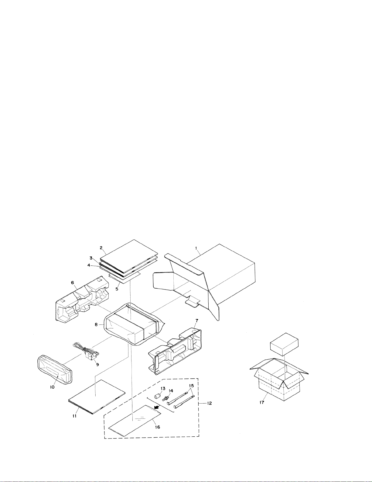
2. EXPLODED VIEWS AND PARTS LIST
2.1 PACKING
Page 3

3
KEH-P1010R,P1013R
NOTE
Parts marked by “*” are generally unavailable because they are not in our Master Spare Parts List.
Mark No. Description Part No. Mark No. Description Part No.
1 Carton CZH5577
2 Owner’s Manual CZR2940
3 Installation Manual CZR2941
* 4 Warranty Card CRY1157
* 5 Passport CRY1013
6 Protector CHP1623
7 Protector CHP1622
8 Polyethylene Bag CZE2903
9 Cord Assy CZD2977
10 Case Assy CXB3520
11 Owner’s Manual CZR2942
* 12 Accessory Assy CEA2397
13 Bush CNV3930
14 Screw CBA1002
15 Handle CNC5395
16 Polyethylene Bag E36-615
17 Contain Box CZH5578
KEH-P1013R/XM/EW
Mark No. Description Part No. Mark No. Description Part No.
1 Carton CZH5579
2 Owner’s Manual CZR2940
3 Installation Manual CZR2941
* 4 Warranty Card CRY1157
* 5 Passport CRY1013
6 Protector CHP1623
7 Protector CHP1622
8 Polyethylene Bag CZE2903
9 Cord Assy CZD2977
10 Case Assy CXB3520
11 Owner’s Manual CZR2942
* 12 Accessory Assy CEA2397
13 Bush CNV3930
14 Screw CBA1002
15 Handle CNC5395
16 Polyethylene Bag E36-615
17 Contain Box CZH5580
Owner's Manual,Installation Manual
Part No.
CZR2940
CZR2941
CZR2942
English, Spanish, German
English, Spanish, German, French, Italian, Dutch
French, Italian, Dutch
Language
PACKING SECTION PARTS LIST
KEH-P1010R/XM/EW
Page 4
4
KEH-P1010R,P1013R
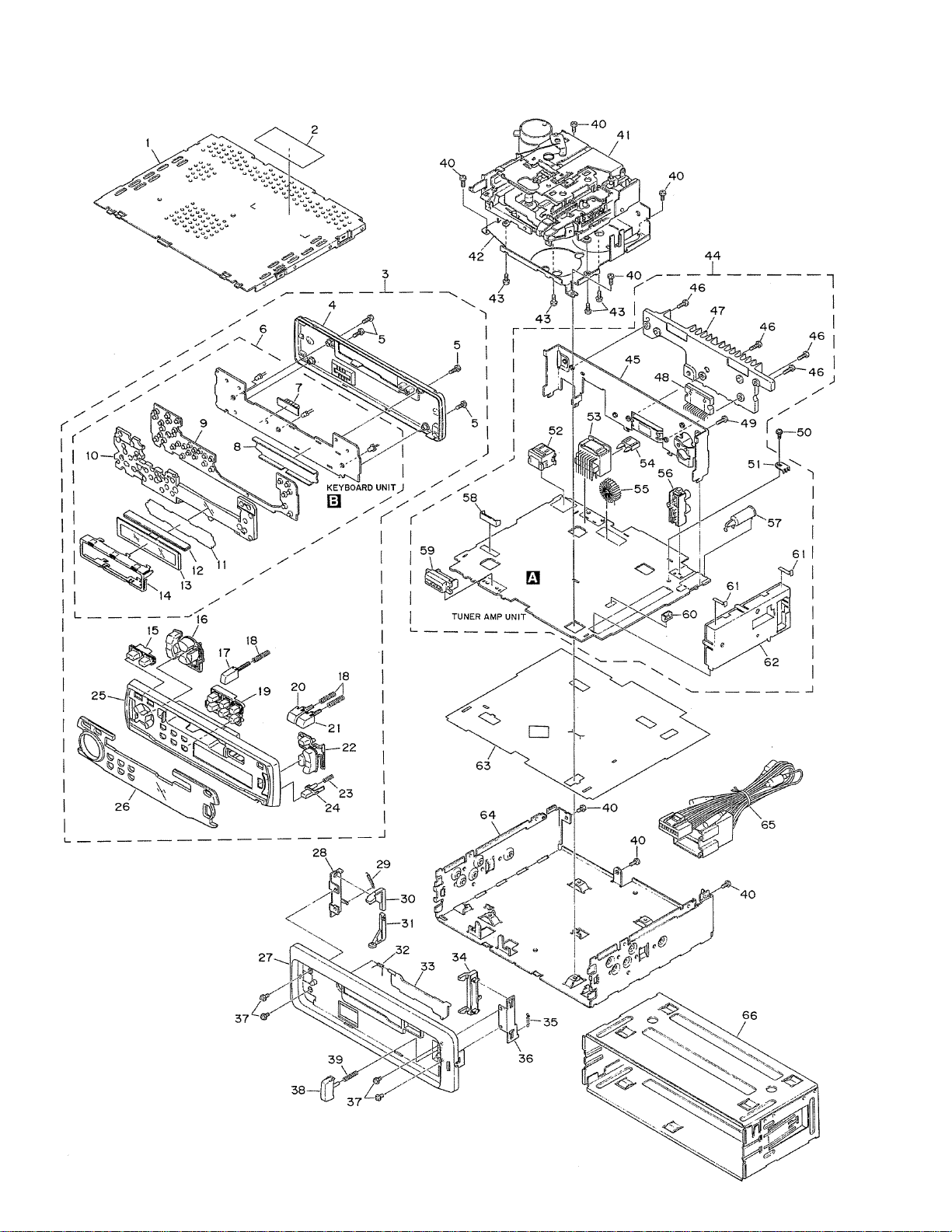
2.2 EXTERIOR
Page 5

5
KEH-P1010R,P1013R
3
4
6
25
26
27
33
64
Grille Unit
Cover
Keyboard Unit
Grille
Plate Assy
Panel
Door
Chassis
CZX5512
CZN6753
CZW5522
CZN6746
CZX5507
CZN6756
CAT2109
CZN6736
CZX5513
CZN6754
CZW5521
CZN6747
CZX5508
CZN6757
CAT2108
CZN6737
1 Case CZN6739
* 2 Label CZA5543
3 Grille Unit
See Contrast table(2)
4 Cover
See Contrast table(2)
5 Screw BPZ20P100FZK
6 Keyboard Unit
See Contrast table(2)
7 Connector(CN900) CKS3580
8 Holder CZN6759
9 Rubber CZN6744
10 Lighting Conductor CZN6758
11 Sheet CZN6760
12 Connector CZN6745
13 LCD(LCD900) CZA5541
14 Holder CZN6743
15 Button (SOURCE) CZA5535
16 Button (CROSS) CZA5532
17 Button (EJECT) CZA5531
18 Spring CZB2976
19 Button (1-6) CZA5533
20 Button (REW) CZA5530
21 Button (FF) CZA5529
22 Button (EQ) CZA5534
23 Spring CZB2977
24 Button CAC5789
25 Grille
See Contrast table(2)
26 Plate Assy
See Contrast table(2)
27 Panel
See Contrast table(2)
28 Bracket CNC6135
29 Spring CBH1834
30 Arm CNV4692
31 Arm CNV4693
32 Spring CBH2126
33 Door
See Contrast table(2)
34 Arm CNV4728
35 Spring CBH1835
36 Bracket CNC6791
37 Screw IMS20P030FZK
38 Button CAC4836
39 Spring CBH1996
40 Screw BSZ26P060FMC
41 Mechanism CZX5514
42 Bracket CZN6738
43 Screw BMZ26P040FMC
44 Tuner Amp Unit CZW5519
45 Panel CZN6741
46 Screw BSZ26P100FMC
47 Heat Sink CZN6740
48 IC(IC500) TA8277H
49 Screw BPZ26P100FZK
50 Screw ISS26P055FUC
51 Terminal(G1) CKF1059
52 Connector(CN600) CKS3408
53 Connector(CN200) CZK2943
54 Fuse(10A) CEK1208
55 Choke Coil (L700) CTH1221
56 Pin Jack(CN700) CKB1041
57 Antenna Jack(CN100) CKX1056
58 Plag (CN300) CZK2946
59 Connector(CN800) CKS3581
60 Plug (CN350) CZK2945
61 Plate CZN6730
62 FM/AM Tuner Unit CHX1442
63 Insulator CZN6742
64 Chassis
See Contrast table(2)
65 Cord Assy CZD2977
66 Holder Unit CXB6681
Mark No. Description Part No. Mark No. Description Part No.
(1)EXTERIOR SECTION PARTS LIST
KEH-P1010R/XM/EW and KEH-P1013R/XM/EW have the same construction except for the following:
(2)CONTRAST TABLE
Mark No.
Symbol and Description
KEH-P1010R/XM/EW
KEH-P1013R/XM/EW
Part No.
Page 6
6
KEH-P1010R,P1013R
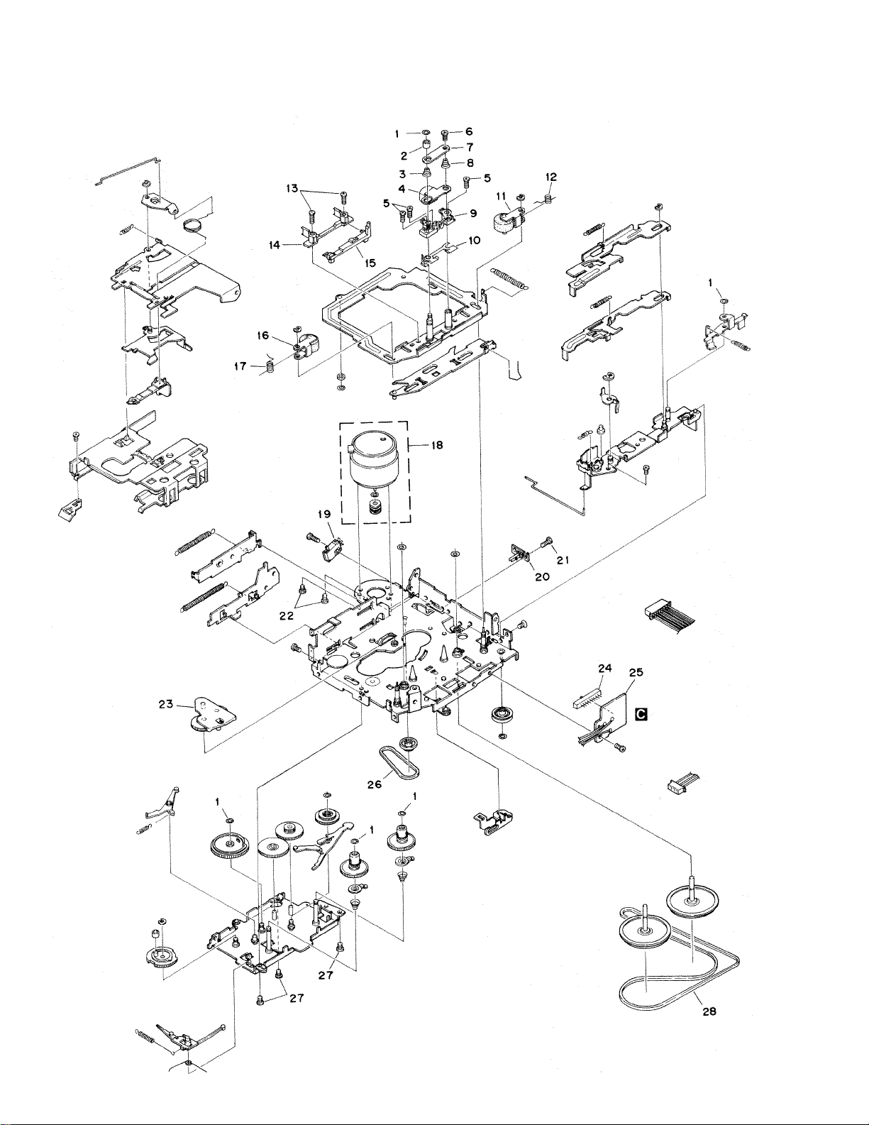
2.3 CASSETTE MECHANISM
Page 7

7
KEH-P1010R,P1013R
1 Washer 1-0036-5024
2 Roller 1-0363-3018
3 Spring 1-0036-4011
4 Head 1-0036-7123
5 Screw 1-0138-5002
6 Screw 2-1012-0040-C2
7 Plate 1-0036-1015
8 Spring 1-0036-4010
9 Arm 10138-2005-3
10 Shim 1-0138-1006
11 Pinch Arm (F) Assy 1-0036-6014
12 Spring 1-0363-4003
13 Screw 2-1032-0070-C2
14 Tape Guide 1-0038-2018
15 Link 1-0363-2006
16 Pinch Arm (R) Assy 1-0036-6013
17 Spring 1-0363-4004
18 Motor Assy (M1) X-0363-7006
19 Power Switch (S1) 1-0363-7005
20 Mute Switch (S2) 1-0363-7001
21 Screw 213317040-C2
22 Screw 2-1032-0025-C2
23 Arm Assy X-0363-6003
24 Slide Switch (S3) 1-0363-7002
25 SW PWB 1-0363-7008
26 Belt 1-0036-5018
27 Screw 213820030-C2
28 Belt 1-0036-5004
Mark No. Description Part No.
CASSETTE MECHANISM SECTION PARTS LIST
NOTE
For the cassette mechanism, only the parts listde here are available as spare parts.
The others (not shown in the list)cannot be supplied.
Page 8
8
KEH-P1010R,P1013R
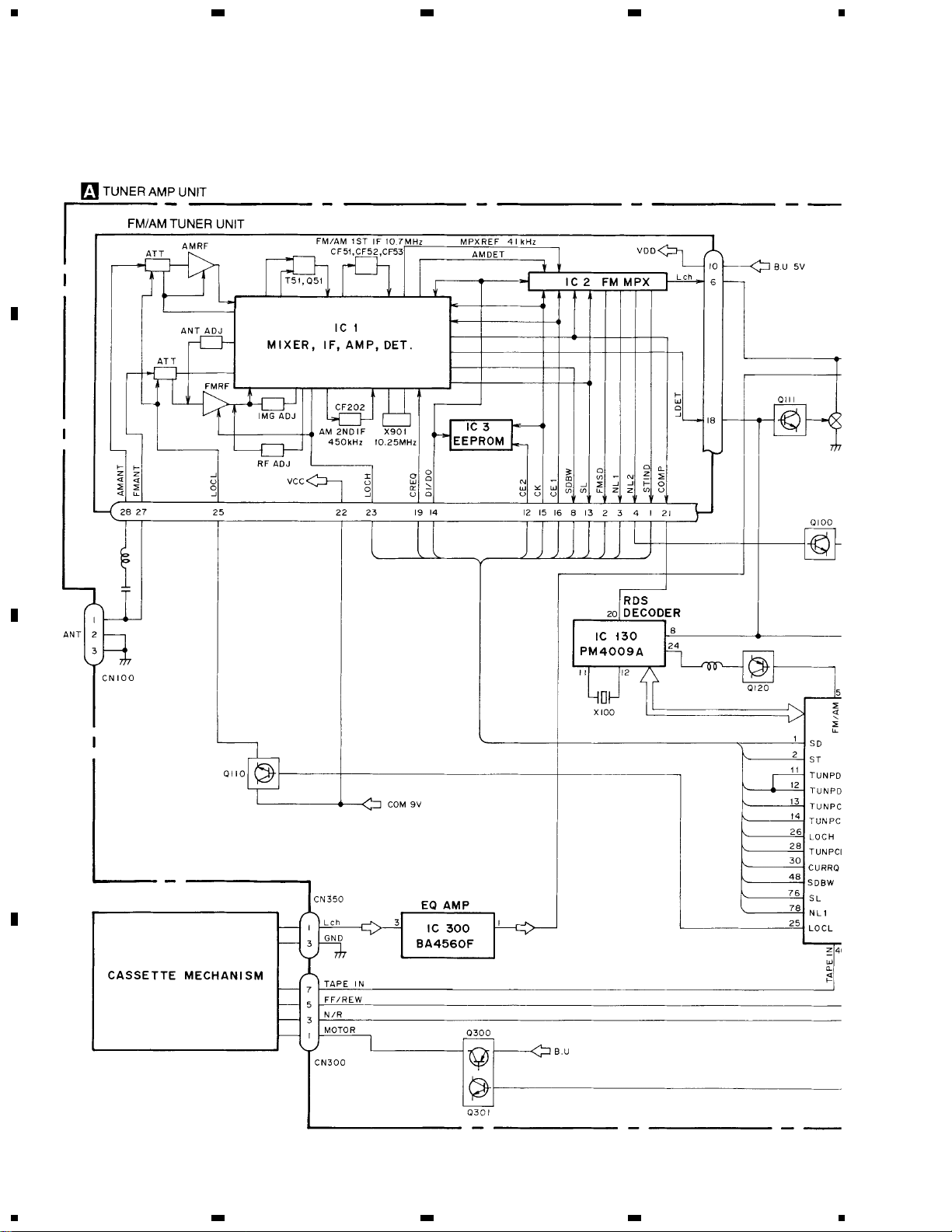
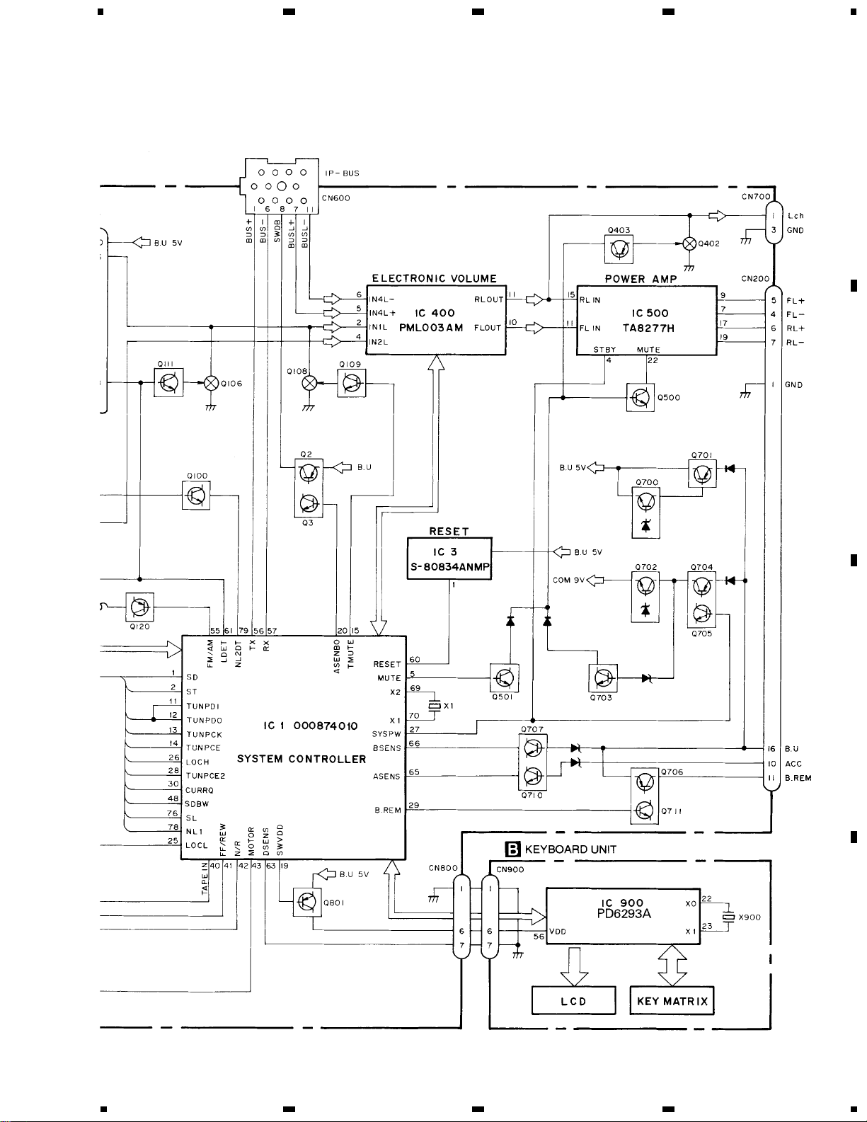
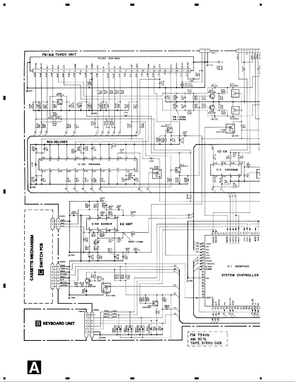
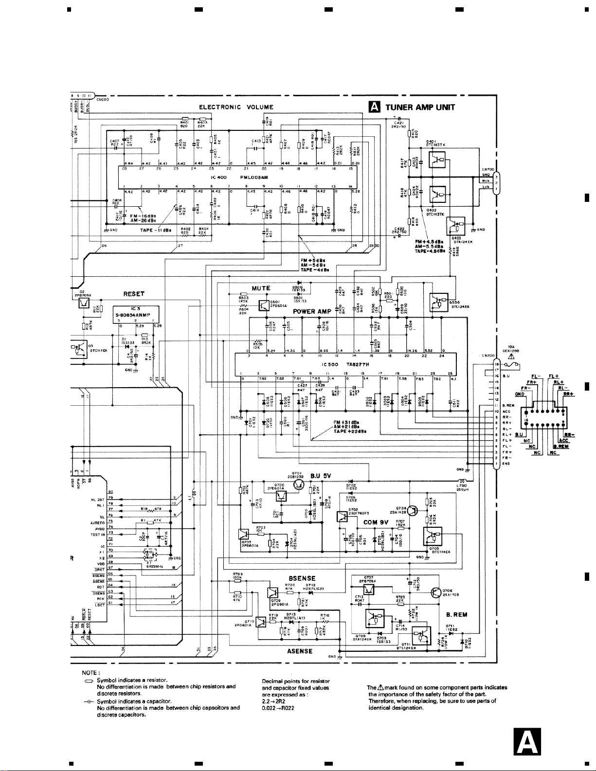
3. BLOCK DIAGRAM AND SCHEMATIC DIAGRAM
3.1 BLOCK DIAGRAM
1
23
4
1234
D
C
B
A
Page 9
9
KEH-P1010R,P1013R
5
6
78
5
6
78
D
C
B
A
Page 10
10
KEH-P1010R,P1013R
3.2 OVERALL CONNECTION DIAGRAM
1
23
4
1
234
D
C
B
A
Page 11
11
KEH-P1010R,P1013R
5
6
78
5
6
7
8
D
C
B
A
Page 12
12
KEH-P1010R,P1013R
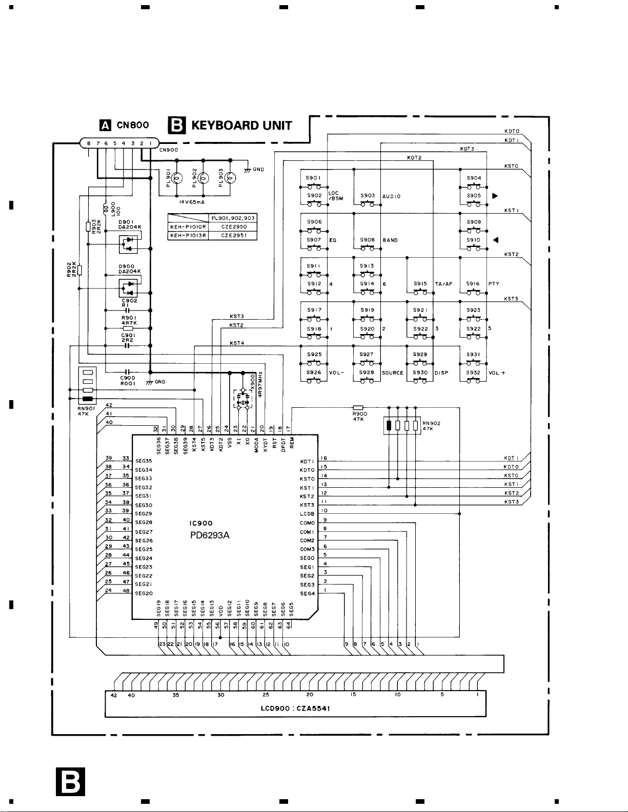
3.3 KEYBOARD UNIT
1
23
4
1234
D
C
B
A
Page 13

13
KEH-P1010R,P1013R
3.4 CASSETTE MECHANISM
1
23
4
1
234
D
C
B
A
Page 14

14
KEH-P1010R,P1013R
4. PCB CONNECTION DIAGRAM
4.1 TUNER AMP UNIT
A
Capacitor
Connector
P.C.Board
Chip Part
SIDE A
SIDE B
NOTE FOR PCB DIAGRAMS
1. The parts mounted on this PCB
include all necessary parts for
several destination.
For further information for
respective destinations, be
sure to check with the
schematic diagram.
1
23
4
1
234
D
C
B
A
Page 15

15
KEH-P1010R,P1013R
A
SIDE A
5
6
78
5
6
78
D
C
B
A
Page 16

16
KEH-P1010R,P1013R
1
23
4
1
234
D
C
B
A
TUNER AMP UNIT
Page 17

17
KEH-P1010R,P1013R
SIDE B
5
6
78
5
6
78
D
C
B
A
Page 18

18
KEH-P1010R,P1013R
4.2 KEYBOARD UNIT
1
23
4
1
234
D
C
B
A
Page 19

19
KEH-P1010R,P1013R
SIDE B
SIDE A
5
6
78
5
6
7
8
D
C
B
A
Page 20

20
KEH-P1010R,P1013R
4.3 CASSETTE MECHANISM
1
23
4
1
234
D
C
B
A
Page 21

21
KEH-P1010R,P1013R
5. ELECTRICAL PARTS LIST
NOTES:
Parts whose parts numbers are omitted are subject to being not supplied.
The part numbers shown below indicate chip components.
Chip Resistor
RS1/_S___J,RS1/__S___J
Chip Capacitor (except for CQS.....)
CKS....., CCS....., CSZS.....
Unit Number :CZW5519
Unit Name :Tuner Amp Unit
MISCELLANEOUS
IC 1 IC 000874010
IC 2 IC CA0008AM
IC 3 IC S-80834ANMP
IC 130 IC PM4009A
IC 300 IC BA4560F
IC 400 IC PML003AM
IC 500 IC TA8277H
Q 2 Transistor 2PB709A
Q 3 Transistor DTC114EK
Q 100 Transistor 2PD601A
Q 105 Transistor 2SD1865
Q 106 Transistor 2SD1865
Q 107 Transistor DTC143TK
Q 108 Transistor DTC143TK
Q 109 Transistor DTC114EK
Q 110 Transistor 2PD601A
Q 111 Transistor 2PD601A
Q 120 Transistor DTA124EK
Q 300 Transistor 2SB1238
Q 301 Transistor DTC114EK
Q 401 Transistor DTC143TK
Q 402 Transistor DTC143TK
Q 403 Transistor DTA124EK
Q 500 Transistor DTC124EK
Q 501 Transistor 2PD601A
Q 700 Transistor 2PD601A
Q 701 Transistor 2SB1238
Q 702 Transistor 2SD1760F5
Q 703 Transistor 2PD601A
Q 704 Transistor 2SA1428
Q 705 Transistor DTC114EK
Q 706 Transistor 2SA1703
Q 707 Transistor 2PB709A
Q 708 Transistor DTA124EK
Q 709 Transistor 2PD601A
Q 710 Transistor 2PD601A
Q 711 Transistor DTC124EK
Q 801 Transistor 2PB709A
D 1 Diode 1SS133
D 300 Diode 11ES2
D 301 Diode 1SS133
D 500 Diode 1SS133
D 501 Diode 1SS133
D 502 Diode 11ES2
D 503 Diode 11ES2
D 504 Diode 11ES2
D 505 Diode 11ES2
D 506 Diode 11ES2
D 507 Diode 11ES2
D 508 Diode 11ES2
D 509 Diode 11ES2
D 700 Diode 11ES2
D 701 Diode 11ES2
D 702 Diode 11ES2
D 703 Diode HZS6L(B2)
D 704 Diode HZS9L(A2)
D 705 Diode HZS9L(B3)
D 706 Diode 11ES2
D 709 Diode 1SS133
D 710 Diode 11ES2
D 711 Diode 11ES2
D 712 Diode HZS7L(C2)
D 713 Diode HZS7L(A1)
D 800 Diode DA204K
D 801 Diode DA204K
D 802 Diode DA204K
D 803 Diode MTZJ6R8(B)
L 1 Ferri-Inductor LAU2R2K
L 3 Ferri-Inductor LAU2R2K
L 100 Ferri-Inductor LAU4R7K
L 101 Ferri-Inductor LAU1R0M
L 102 Inductor LAU100K
L 103 Ferri-Inductor LAU1R0M
L 104 Ferri-Inductor LAU101K
L 700 Choke Coil 250uH CTH1221
=====Circuit Symbol and No.===Part Name Part No.
--- ------ ------------------------------------------ -------------------------
=====Circuit Symbol and No.===Part Name Part No.
--- ------ ------------------------------------------ -------------------------
Page 22

22
KEH-P1010R,P1013R
L 801 Inductor LAU100K
G 1 Terminal CKF1059
X 1 Ceramic Resonator 6.29MHz CSS1310
X 100 Crystal Resonator 3.648MHz CSS1447
JC 101 RS1/16S0R0J
TU 100 FM/AM Tuner Unit CHX1442
DSP
100 Surge Protector DSP-200-A11F
RESISTORS
R 1 RS1/16S473J
R 3 RS1/16S102J
R 4 RS1/16S102J
R 5 RS1/16S473J
R 6 RS1/16S473J
R 7 RD1/4PU102J
R 8 RS1/16S101J
R 9 RS1/16S101J
R 10 RD1/4PU620J
R 11 RS1/16S223J
R 12 RS1/16S472J
R 13 RS1/16S822J
R 14 RD1/4PU102J
R 15 RD1/4PU222J
R 18 RD1/4PU473J
R 101 RS1/16S474J
R 102 RS1/16S681J
R 103 RS1/16S153J
R 104 RS1/16S681J
R 105 RS1/16S473J
R 106 RS1/16S681J
R 107 RS1/16S473J
R 108 RS1/16S681J
R 109 RS1/16S473J
R 110 RD1/4PU102J
R 111 RS1/16S681J
R 112 RS1/16S103J
R 113 RS1/16S681J
R 114 RS1/16S681J
R 115 RS1/16S681J
R 116 RD1/4PU681J
R 117 RS1/16S681J
R 118 RS1/16S473J
R 119 RD1/4PU473J
R 120 RS1/16S393J
R 121 RS1/16S472J
R 122 RS1/16S473J
R 123 RS1/16S473J
R 124 RS1/16S222J
R 125 RS1/16S222J
R 126 RS1/16S224J
R 127 RD1/4PU162J
R 128 RD1/4PU162J
R 129 RS1/16S272J
R 130 RS1/16S272J
R 131 RS1/16S224J
R 132 RS1/16S224J
R 133 RS1/16S223J
R 134 RS1/16S223J
R 135 RS1/16S222J
R 136 RS1/16S222J
R 137 RD1/4PU103J
R 140 RD1/4PU473J
R 141 RS1/16S225J
R 142 RD1/4PU102J
R 143 RS1/16S102J
R 144 RS1/16S102J
R 145 RS1/16S102J
R 146 RD1/4PU681J
R 147 RS1/16S0R0J
R 301 RS1/16S473J
R 302 RS1/16S473J
R 303 RS1/16S330J
R 304 RS1/16S330J
R 305 RS1/16S153J
R 306 RS1/16S153J
R 307 RS1/16S564J
R 308 RS1/16S564J
R 309 RS1/16S102J
R 310 RS1/16S102J
R 311 RS1/16S103J
R 312 RS1/16S103J
R 313 RS1/16S103J
R 314 RD1/2PM102J
R 315 RD1/4PU104J
R 316 RD1/4PU104J
R 317 RD1/4PU104J
R 318 RD1/4PU1R5J
R 319 RD1/4PU1R5J
R 320 RS1/16S101J
R 401 RS1/16S821J
R 402 RD1/4PU821J
R 403 RS1/16S223J
R 404 RD1/4PU223J
R 405 RS1/16S102J
R 406 RD1/4PU102J
R 407 RS1/16S0R0J
R 408 RS1/16S0R0J
R 409 RS1/16S0R0J
R 410 RS1/16S0R0J
=====Circuit Symbol and No.===Part Name Part No.
--- ------ ------------------------------------------ -------------------------
=====Circuit Symbol and No.===Part Name Part No.
--- ------ ------------------------------------------ -------------------------
Page 23

23
KEH-P1010R,P1013R
R 411 RD1/4PU222J
R 413 RD1/4PU222J
R 415 RS1/16S821J
R 416 RS1/16S821J
R 417 RS1/16S473J
R 418 RS1/16S473J
R 419 RD1/4PU562J
R 421 RS1/16S472J
R 422 RS1/16S472J
R 500 RS1/16S101J
R 501 RS1/16S221J
R 502 RS1/16S103J
R 503 RS1/16S152J
R 504 RD1/4PU223J
R 505 RD1/4PU103J
R 506 RS1/16S153J
R 701 RS1/16S223J
R 702 RS1/16S472J
R 703 RS1/16S103J
R 704 RS1/16S223J
R 705 RS1/16S223J
R 706 RS1/16S102J
R 707 RS1/16S122J
R 708 RS1/16S0R0J
R 709 RS1/16S104J
R 710 RS1/16S473J
R 716 RD1/4PU102J
R 717 RS1/16S472J
R 718 RS1/16S473J
R 719 RS1/16S223J
R 720 RS1/16S473J
R 721 RS1/16S473J
R 722 RD1/2PM102J
R 723 RS1/16S223J
R 724 RD1/2PM102J
R 801 RS1/16S222J
R 802 RS1/16S222J
R 803 RS1/16S222J
R 804 RD1/4PU473J
R 805 RD1/4PU222J
R 806 RS1/16S223J
R 807 RD1/4PU222J
CAPACITORS
C 1 CEAL4R7M16
C 2 CCSRCH101J50
C 3 CKSRYB102K50
C 4 CEAL2R2M50
C 5 CKSRYB104K25
C 101 CKSRYB103K50
C 102 CKSRYB472K50
C 103 CKSRYB473K25
C 104 CEAL101M10
C 105 CKSRYB182K50
C 106 CKSRYB223K25
C 107 CKSRYB223K25
C 108 CKSRYB223K25
C 109 CKSRYB103K50
C 110 CKSRYB103K50
C 111 CEAL2R2M50
C 112 CEAL2R2M50
C 113 CKSRYB103K50
C 114 CEAL101M10
C 115 CKSRYB472K50
C 116 CKSRYB222K50
C 117 CKSRYB222K50
C 118 CKSRYB473K25
C 119 CCSRCH101J50
C 120 CEAL220M10
C 121 CKSRYB104K25
C 122 CEAL220M10
C 123 CKSRYB104K25
C 124 CCSRCH471J50
C 125 CCSRCH471J50
C 126 CKSRYB104K25
C 127 CCSRCH270J50
C 128 CCSRCH270J50
C 301 CCSRCH471J50
C 303 CKSRYB102K50
C 304 CKSRYB102K50
C 305 CEAL101M10
C 306 CEAL101M10
C 307 CKSRYB103K50
C 308 CKSRYB103K50
C 309 CCSRCH101J50
C 310 CCSRCH101J50
C 311 CEAL330M10
C 312 CEAL100M16
C 313 CKSRYB103K50
C 401 CKSRYB105K10
C 402 CKSRYB105K10
C 403 CKSRYB105K10
C 404 CKSRYB105K10
C 405 CKSRYB224K10
C 406 CKSRYB224K10
C 407 CKSRYB224K10
C 408 CKSRYB224K10
C 409 CKSRYB104K25
C 410 CEAL470M10
=====Circuit Symbol and No.===Part Name Part No.
--- ------ ------------------------------------------ -------------------------
=====Circuit Symbol and No.===Part Name Part No.
--- ------ ------------------------------------------ -------------------------
Page 24

24
KEH-P1010R,P1013R
C 411 CEAL100M16
C 413 CKSRYB105K10
C 414 CKSRYB105K10
C 415 CKSRYB103K50
C 416 CKSRYB103K50
C 417 CKSRYB472K50
C 418 CKSRYB472K50
C 419 CKSRYB103K50
C 420 CKSRYB103K50
C 421 CEAL2R2M50
C 422 CEAL2R2M50
C 423 CKSRYB222K50
C 424 CKSRYB222K50
C 427 CKSRYB474K10
C 428 CKSRYB474K10
C 429 CKSRYB474K10
C 430 CKSRYB474K10
C 431 CKSRYB474K10
C 432 CKSRYB474K10
C 433 CKSRYB474K10
C 434 CKSRYB474K10
C 500 CKSRYB104K25
C 501 3300µF/16V CCH1018
C 502 CKSRYB474K10
C 503 CKSRYB474K10
C 504 CKSRYB105K10
C 505 CKSRYB105K10
C 506 CKSRYB473K25
C 508 CEAL100M16
C 509 CEAL330M10
C 511 CKSRYB224K10
C 700 CEA471M16
C 701 CKSRYB103K50
C 703 CEAL470M10
C 704 CEAL101M10
C 705 CKSRYB103K50
C 706 CEAL101M10
C 709 CKSRYB102K50
C 712 CEAL3R3M50
C 713 CKSRYB473K25
C 714 CEALR10M50
C 801 CCSRCH101J50
C 803 CCSRCH101J50
Unit Number :CZW5522(KEH-P1010R/XM/EW)
:CZW5521(KEH-P1013R/XM/EW)
Unit Name :Keyboard Unit
MISCELLANEOUS
IC 900 IC PD6293A
D 900 Diode DA204K
D 901 Diode DA204K
L 900 Ferri-Inductor LAU101K
X 900 Ceramic Resonator 4.97MHz CSS1422
PL 901 Lamp 14V 65mA See Contrast table
PL 902 Lamp 14V 65mA See Contrast table
PL 903 Lamp 14V 65mA See Contrast table
RN 901 RAB4C473J
RN 902 RAB4C473J
LCD
900 LCD CZA5541
RESISTORS
R 900 RS1/16S473J
R 901 RS1/16S472J
R 902 RS1/16S222J
R 903 RS1/16S222J
CAPACITORS
C 900 CKSRYB102K50
C 901 CKSQYB225K10
C 902 CKSRYB104K25
Unit Number :
Unit Name :Switch PCB
S 3 Slide Switch(FWD/REV) 1-0363-7002
Miscellaneous Parts List
S 1 Switch(TAPE/TUN) 1-0363-7005
S 2 Switch(Mute) 1-0363-7001
M 1 Motor Assy X-0363-7006
HD 1 Head 1-0036-7123
=====Circuit Symbol and No.===Part Name Part No.
--- ------ ------------------------------------------ -------------------------
=====Circuit Symbol and No.===Part Name Part No.
--- ------ ------------------------------------------ -------------------------
KEH-P1010R/XM/EW and KEH-P1013R/XM/EW have the same construction except for the following:
CONTRAST TABLE of KEYBOARD UNIT
Symbol and Description
PL 901
PL 902
PL 903
CZE2950
CZE2950
CZE2950
CZE2951
CZE2951
CZE2951
KEH-P1010R/XM/EW
KEH-P1013R/XM/EW
Part No.
Page 25

25
KEH-P1010R,P1013R
6. ADJUSTMENT
There is no information to be shown in this chapter.
Page 26

26
KEH-P1010R,P1013R
7. GENERAL INFORMATION
7.1 DIAGNOSIS
7.1.1 DISASSEMBLY
Removing the Upper Case(not shown)
1.Remove the Upper Case.
Removing the Cassette Mechanism Module(Fig.1)
Remove the four screws and then remove the
Cassette Mechanism.
Remove the Grille Assy(Fig.1)
Remove the two screws.
Disconnect the two stoppers and then remove
the Grille Assy.
Removing the Tuner Amp Unit(Fig.2)
Remove the three screws.
Remove the screw.
Unbend the five claws and then remove
the Tuner Amp Unit.
Fig. 1
Fig. 2
Page 27

27
KEH-P1010R,P1013R
7.1.2 CONNECTOR FUNCTION DESCRIPTION
Page 28

28
KEH-P1010R,P1013R
BA4560F CA0008AM S-80834ANMP
TB2118F
TA8277H
TAB
GND2
STBY
VCC2
RIP
IN1
IN2
PRE-GND
IN4
IN3
AUX IN
OUT3(+)OUT3(+)
GND3
OUT3(-)
VCC1
OUT4(+)
MUTE
OUT4(-)
GND4
CRIP OUT
1 2 3 4 5 6 7 8 910111213141516171819202122232425
OUT2(-)
OUT2(+)
OUT1(-)
GND1
OUT1(+)
+
–
+
–
+
–
+
–
+
–
+
–
+
–
+
–
7.2 PARTS
7.2.1 IC
Page 29

29
KEH-P1010R,P1013R
* PD6293A
IC's marked by * are MOS type.
Be careful in handling them because they are very liable to be
damaged by electrostatic induction
Page 30

30
KEH-P1010R,P1013R
Pin No. Pin Name I/O Format Function and Operation
1 SD I SD signal input
2 ST I FM stereo input
3 ADPW O A/D converter power supply control output
4 AVSS GND
5 MUTE O C System mute output
6 NC Not used
7 AVREF1 O C A/D converter reference voltage terminal
8 KYDT I Display data input
9 DPDT O C Key data output
10 NC Not used
11 TUNPDI I PLL IC data input
12 TUNPDO O C PLL IC data output
13 TUNPCK O C PLL IC clock output
14 TUNPCE O C PLL IC chip enable output
15 TMUTE O C Tuner mute output
16-18 NC Not used
19 SWVDD O C Grille chip enable output
20 ASENBO O C Slave power supply control output
21 IPPW O C Power supply control output for IP BUS interface IC
22 VST O C Strobe pulse output for electronic volume
23 VCK O C Clock output for electronic volume
24 VDT O C data output for electronic volume
25 LOCK O C Local L output
26 LOCH O C Local H output
27 SYSPW O C System power output
28 TUNPCE2 O C EEPROM chip enable output
29 BREM O C System power ON/OFF output
30 CURRQ O C Tuner voltage FIX output
31,32 NC Not used
33 VSS GND
34-39 NC Not used
40 TAPE IN I TAPE pack-in detection input
41 FF/REW I FF/REW detection input
42 N/R I Cassette mechanism tape direction input
43 MOTOR O C MOTOR power supply control output
44 NC C Not used
45 PEE O C Beep tone output
46 NC Not used
47 RDS57K I RDS 57kHz pulse count input
48 SDBW I SD input at NF
49-54 NC Not used
55 FM/ AM O C FM/AM band select pin “H” : AM “L” : FM
56 TX O C IP BUS data output
57 RX I IP BUS data input
58 NC Not used
59 RDSLK I RDS LK input
60 RESET I Reset input
61 IDET I PLL lock detect input
62 RCK I RDS clock input
63 DSENS I Grille detach sense input
64 RDT I RDS data input
65 ASENS I ACC power sense input
66 BSENS I Back up power sense input
67 DRST O C RDS reset output
68 VDD Power supply
69 X2 Crystal oscillator connection pin
70 X1 Crystal oscillator connection pin
71 IC (GND)
72 XT2 Not used
73 TESTIN I Test program mode input
74 AVDD S/D converter power supply terminal
75 AVREF0 I S/D converter reference voltage terminal
76 SL I Signal level input
77 NC I Not used
78 NL1 I RDS noise level input 1
79 NL2DT I RDS noise level input 2
80 NC Not used
Pin Functions(000874010)
Format Meaning
C C MOS
Page 31

31
KEH-P1010R,P1013R
* 000874010
- FM/AM Tuner Unit
Page 32

32
KEH-P1010R,P1013R
7.2.2 DISPLAY
CZA5541
Page 33

33
KEH-P1010R,P1013R
7.3 OPERATIONAL FLOW CHART
Page 34

34
KEH-P1010R,P1013R
8. OPERATIONS AND SPECIFICATIONS
Key Finder
Head Unit
/
/
DISPLAY button
SOURCE button
EJECT button
Cassette door
buttons
LOCAL/BSM button
BAND button
AUDIO button
buttons
TA/AF button
PTY button
Detach button
EQ button
Buttons 1–6
+/– buttons
Page 35

35
KEH-P1010R,P1013R
Basic Operation
To Listen to Music
The following explains the initial operations required before you can listen to music.
Note:
• Loading a cassette in this product.
1.
Select the desired source (e.g. Tuner).
Each press of the SOURCE button selects the desired source in the following order:
Tuner Cassette player Multi-CD player External Unit
Note:
• External Unit refers to a Pioneer product (such as one available in the future) that, although incom-
patible as a source, enables control of basic functions by this product. Only one External Unit can
be controlled by this product.
• In the following cases, the sound source will not change:
* When a product corresponding to each source is not connected to this product.
* When no tape is set in this product.
* When no magazine is set in the Multi-CD player.
• When this product’s blue/white lead is connected to the car’s Auto-antenna relay control terminal,
the car’s Auto-antenna extends when this product’s source is switched ON. To retract the antenna,
switch the source OFF.
2. Raise or lower the volume.
3. Turn the source OFF.
Hold for 1 second
Each press changes the Source ...
Basic Operation
Basic Operation of Tuner
This product’s AF function can be switched ON and OFF. AF should be switched OFF
for normal tuning operations.
Manual and Seek Tuning
• You can select the tuning method by changing the length
of time you press the button.
Manual Tuning (step by step) 0.5 seconds or less
Seek Tuning 0.5 seconds or more
Note:
• If you continue pressing the button for longer than 0.5 seconds, you can skip
broadcast stations. Seek Tuning starts as soon as you release the button.
• Stereo indicator “” lights when a stereo station is selected.
Preset Tuning
• You can memorize broadcast stations in buttons
1 through 6 for easy, one-touch station recall.
Preset station recall 2 seconds or less
Broadcast station preset memory 2 seconds or more
Note:
• Up to 12 FM stations (6 each in F1 (FM1) and F2 (FM2)) and
6 MW/LW stations can be stored in memory.
Band
F1 (FM1) F2 (FM2)
MW/LW
Preset Number Indicator
Band Indicator
Frequency Indicator
/
Page 36

36
KEH-P1010R,P1013R
Basic Operation of Multi-CD Player
This product can control a Multi-CD player (sold separately).
Basic Operation
Track Search and Fast Forward/Reverse
• You can select between Track Search or Fast
Forward/Reverse by pressing the button
for a different length of time.
Track Search 0.5 seconds or less
Fast Forward/Reverse Continue pressing
Disc Number Search (for 6-Disc, 12-Disc types)
• You can select discs directly with the 1 to 6 buttons. Just press the number
corresponding to the disc you want to listen to.
Note:
• When a 12-Disc Multi-CD Player is connected and you want to select disc 7 to 12, press the 1 to 6
buttons for 2 seconds.
Note:
• The Multi-CD Player may perform a preparatory operation, such as verifying the presence of a
disc or reading disc information, when the power is turned ON or a new disc is selected for play-
back. “READY” is displayed.
• If the Multi-CD Player cannot operate properly, an error message such as “ERROR-14” is dis-
played. Refer to the Multi-CD Player owner’s manual.
• If there are no discs in the Multi-CD Player magazine, “NO DISC” is displayed.
• You can not operate the 50-Disc Type Multi-CD Player with this product.
Play Time Indicator
Switching the Display
Each press of the DISPLAY button changes the display in
the following order:
Playback mode (Play Time) Disc and Track Number
Basic Operation of Cassette Player
Fast Forward/Rewind
• To select Fast Forward, press the button for the same direction as
the direction indicator.
• To select Rewind, press the button for the opposite direction as the
direction indicator.
Note:
• To release Fast Forward/Rewind, lightly press the or button located on the
opposite side of the one you pressed to Fast Forward or Rewind.
Eject
Note:
• The Tape function can be turned ON/OFF with
the cassette tape remaining in this product.
Direction Indicator
Cassette Loading Slot
Direction Change
• To change the
direction, press
the and
buttons at the
same time.
/
Page 37

37
KEH-P1010R,P1013R
1*
2*
4*
3*
5*
Connect leads of the
same color to each
other.
Cap (1*)
When not using this terminal,
do not remove the cap.
ISO connector
Yellow (2*)
Toterminal always supplied
with power regardless of
ignition switch position.
Red (4*)
Toelectric terminal controlled
by ignition switch (12 V DC)
ON/OFF.
Yellow (3*)
Back-up
(or accessory)
Red (5*)
Accessory
(or back-up)
Black (ground)
Tovehicle (metal) body.
Note:
In some vehicles, the ISO connector may be
divided into two. In this case, be sure to
connect to both connectors.
Blue/white
(7*)
Blue/white
(6*)
The pin position of the
ISO connector will differ
depends on the type of
vehicle. Connect 6*
and 7* when Pin 5 is an
antenna control type.
In another type of
vehicle, never connect
6* and 7*.
Blue/white
Tosystem control terminal
of the power amp (max. 300 mA 12 V
DC).
ToAuto-antenna relay control
terminal (max. 300 mA12 V DC).
Note:
Depending on the kind of vehicle, the function
of 3* and 5* may be different. In this case, be
sure to connect 2* to 5* and 4* to 3*.
Speaker leads
White
White/black
Gray
Gray/black
: Front left
: Front left
: Front right
: Front right
Green
Green/blackVV
iolet
iolet/black
: Rear left
: Rear left
: Rear right
: Rear right
Multi-CD player
(sold separately)
Connecting cords
with RCA pin plugs
(sold separately)
System remote control
Rear speaker
Perform these connections when using a
different amp (sold separately).
Power amp
(sold separately)
Rear speaker
This Product
IP-BUS input (Blue)
Antenna jack
Fuse
Rear output
IP-BUS cable
Page 38

KEH-P1010R,P1013R
Specifications
General
Power source .......... 14.4 V DC (10.8 – 15.1 V allowable)
Grounding system ........................................ Negative type
Max. current consumption ........................................ 8.5 A
Dimensions
(mounting size) ...... 178 (W) × 50 (H) × 155 (D) mm
(front face) .............. 188 (W) × 58 (H) × 19 (D) mm
Weight
Buckup current
......................................................................
.....................................................
1.2 kg
4.3 mA
Amplifier
Maximum power output ...................................... 45 W × 4
Continuous power output .................................... 25 W × 4
(DIN45324, +B = 14.4 V)
Load impedance .......................... 4 Ω (4 – 8 Ω allowable)
Preout maximum output level/output impedance
.................................................................. 2.2 V /1 kΩ
Equalizer (3 band equalizer)
(Low) .............................................................. ±12 dB
(Mid) .............................................................. ±12 dB
(High) ............................................................ ±12 dB
Loudness contour
(Low) .................. +3.5 dB (100 Hz), +3 dB (10 kHz)
(Mid) ................ +10 dB (100 Hz), +6.5 dB (10 kHz)
(High) ................ +11 dB (100 Hz), +11 dB (10 kHz)
(volume: –30 dB)
Cassette player
Tape
........................ Compact cassette tape (C-30 – C-90)
Tape speed
................
Fast forward/rewinding time .... Approx. 100 sec. for C-60
Wow & flutter
.......................................... 0.13% (WRMS)
Frequency response
...................... 30 – 16,000 Hz (±3 dB)
Stereo separation ...................................................... 45 dB
Signal-to-noise ratio
.................... 41 dB (IEC-A network)
FM tuner
Frequency range ...................................... 87.5 – 108 MHz
Usable sensitivity ...................................................... 9 dBf
(0.77 µV/75 Ω, mono, S/N: 30 dB)
50 dB quieting sensitivity ........................................ 15 dBf
(1.5 µV/75 Ω, mono)
Signal-to-noise ratio ...................... 70 dB (IEC-A network)
Distortion .......................... 0.3% (at 65 dBf, 1 kHz, stereo)
Frequency response ...................... 30 – 15,000 Hz (±3 dB)
Stereo separation .......................... 40 dB (at 65 dBf, 1 kHz)
MW tuner
Frequency range ........................ 531 – 1,602 kHz (9 kHz)
Usable sensitivity .............................. 18 µV (S/N: 20 dB)
Selectivity .................................................. 50 dB (±9 kHz)
LW tuner
Frequency range ........................................ 153 – 281 kHz
Usable sensitivity .............................. 30 µV (S/N: 20 dB)
Selectivity .................................................. 50 dB (±9 kHz)
Note:
• Specifications and the design are subject to possible modification without notice due to improvements.
4.76 cm/sec.(+0.14cm/sec.,-0.05cm/sec.)
 Loading...