

Page 1
PIONEER ELECTRONIC CORPORATION 4-1, Meguro 1-Chome, Meguro-ku, Tokyo 153-8654, Japan
PIONEER ELECTRONICS SERVICE INC. P.O.Box 1760, Long Beach, CA 90801-1760 U.S.A.
PIONEER ELECTRONIC [EUROPE] N.V. Haven 1087 Keetberglaan 1, 9120 Melsele, Belgium
PIONEER ELECTRONICS ASIACENTRE PTE.LTD. 253 Alexandra Road, #04-01, Singapore 159936
C PIONEER ELECTRONIC CORPORATION 1999
K-ZZB. MAY 1999 Printed in Japan
ORDER NO.
CRT2343
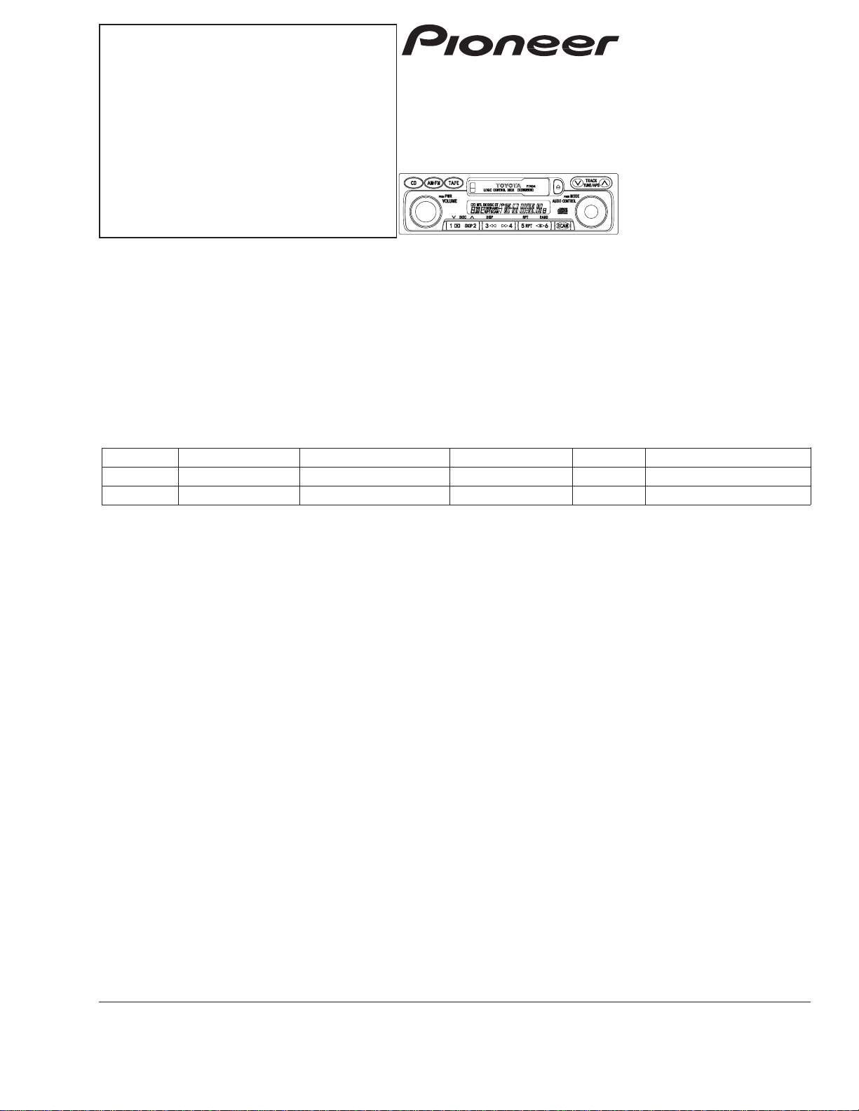
MULTI CD CONTROL FM/AM CASSETTE DECK
KEH-M2096ZT ES
KEH-M2196ZT ES
NOTE:
- The cassette mechanism employed in this model is one of 2L series.
- See the separate manual CX-529 (CRT1507) for the cassette mechanism description.
- Dolby noise reduction manufactured under license from Dolby Laboratories Licensing Corporation.
"Dolby" and the double-D symbol are trademarks of Dolby Laboratories Licensing Corporation.
KEH-M2096ZT/ES
TOYOTA
VEHICLE DESTINATION PRODUCED AFTER PART No. ID No. PIONEER MODEL No.
CAMRY MIDDLE EAST July 1999 86120-06100 P7404 KEH-M2096ZT/ES
CAMRY MIDDLE EAST July 1999 86120-06090 P7405 KEH-M2196ZT/ES
CONTENTS
1. SAFETY INFORMATION............................................2
2. EXPLODED VIEWS AND PARTS LIST ......................3
3. BLOCK DIAGRAM AND SCHEMATIC DIAGRAM ....8
4. PCB CONNECTION DIAGRAM................................22
5. ELECTRICAL PARTS LIST........................................31
6. ADJUSTMENT.........................................................39
7. GENERAL INFORMATION.......................................41
7.1 DIAGNOSIS .......................................................41
7.1.1 TEST MODE .............................................41
7.1.2 SELF-DIAGNOSTIC FUNCTION ..............42
7.1.3 DISASSEMBLY.........................................46
7.1.4 CONNECTOR FUNCTION DESCRIPTION ......47
7.2 PARTS ................................................................48
7.2.1 IC...............................................................48
7.2.2 DISPLAY ...................................................50
7.3 SYSTEM BLOCK DIAGRAM .............................51
8. OPERATIONS AND SPECIFICATIONS....................52
Page 2

2
KEH-M2096ZT,M2196ZT
1. SAFETY INFORMATION
This service manual is intended for qualified service technicians; it is not meant for the casual do-it-yourselfer.
Qualified technicians have the necessary test equipment and tools, and have been trained to properly and safely repair
complex products such as those covered by this manual.
Improperly performed repairs can adversely affect the safety and reliability of the product and may void the warranty.
If you are not qualified to perform the repair of this product properly and safely; you should not risk trying to do so
and refer the repair to a qualified service technician.
- Service Precautions
1. During disassembly, be sure to turn the power off
since an internal IC might be destroyed when a
connector is plugged or unplugged.
2. Whenever the amplifier may be put into operation, a
heat sink should be mounted. ICs and transistors
may be damaged if the amplifier should be put into
operation without mounting any heat sink.
3. When operating with large output power, the heat
sink becomes very hot. Be careful not to touch it.
Page 3
3
KEH-M2096ZT,M2196ZT
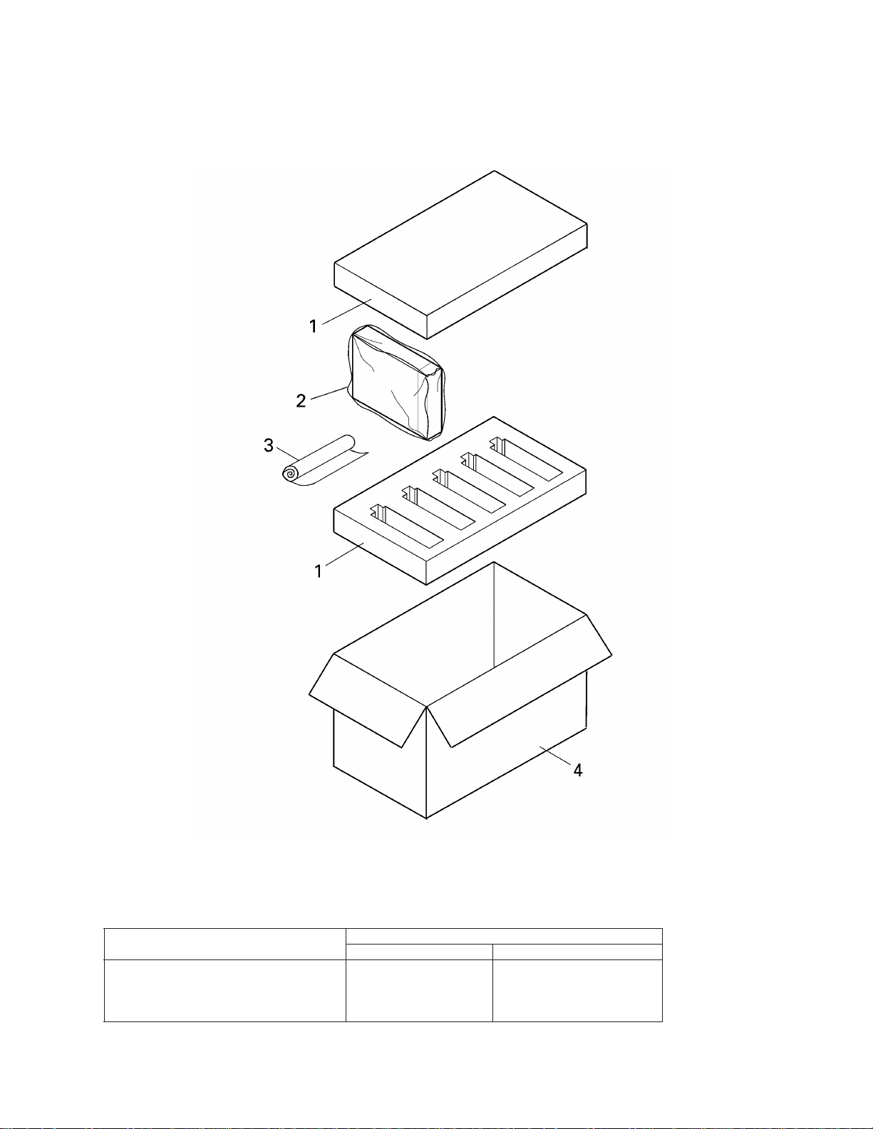
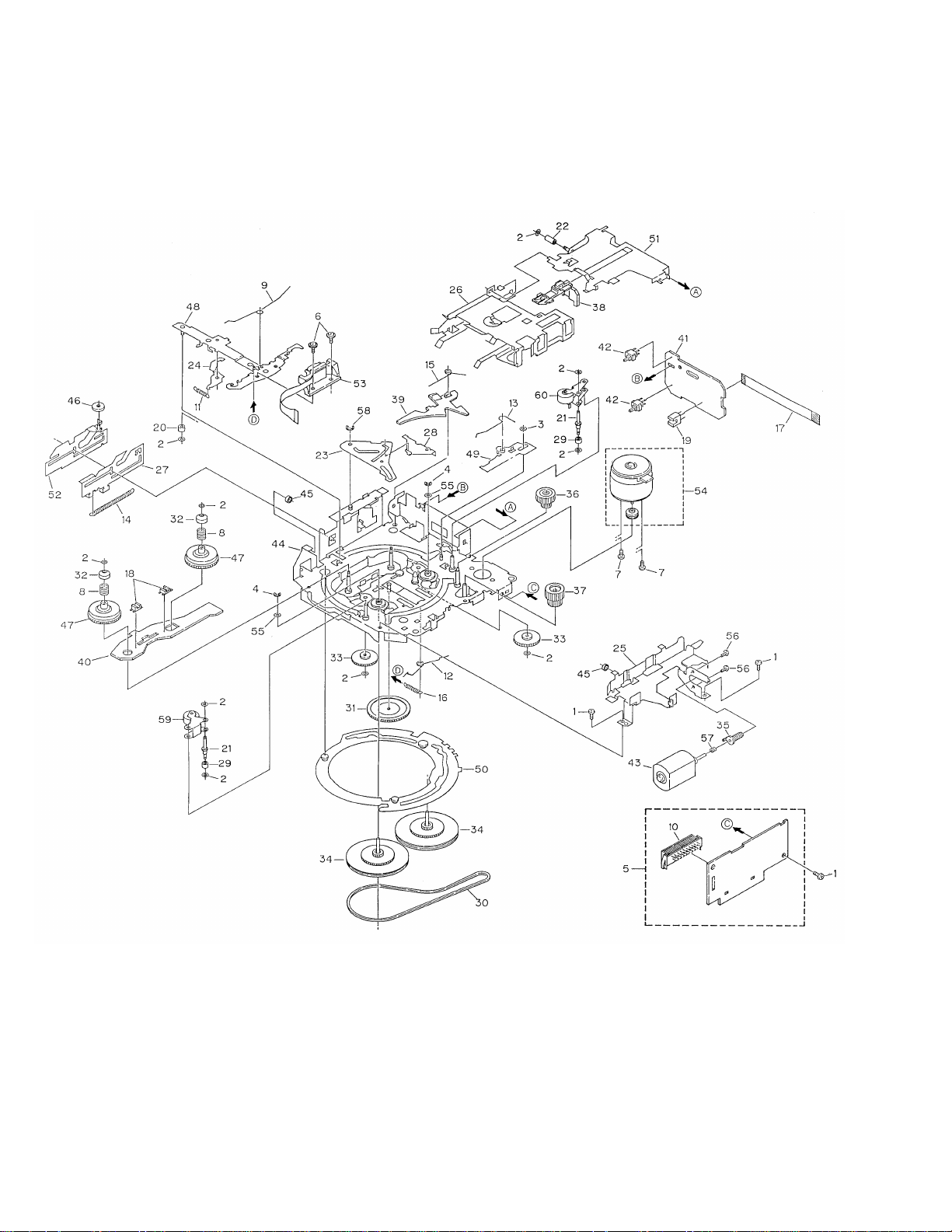
2. EXPLODED VIEWS AND PARTS LIST
2.1 PACKING
NOTE:
- Parts marked by “*” are generally unavailable because they are not in our Master Spare Parts List.
- Screws adjacent to
∇ mark on the product are used for disassembly.
Part No.
Mark No. Description KEH-M2096ZT/ES KEH-M2196ZT/ES
1 Protector CHP2159 CHP2159
2 Polyethylene Bag CEG-162 CEG-162
3 Cover CEG1057 CEG1057
4 Contain Box CHL3798 CHL3799
Page 4
4
KEH-M2096ZT,M2196ZT
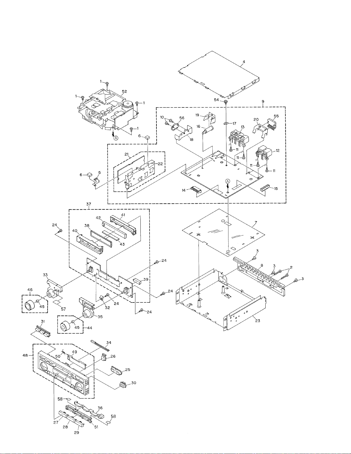
2.2 EXTERIOR
Page 5
5
KEH-M2096ZT,M2196ZT
(1) EXTERIOR SECTION PARTS LIST
Mark No. Description Part No.
Mark No. Description Part No.
1 Screw BMZ26P050FMC
2 Screw BMZ26P180FMC
3 Screw BMZ30P060FMC
4 Case CNB2460
5 Holder CNC7121
* 6 Cushion CNM5281
7 Insulator CNM6079
8 Heat Sink CNR1510
9 Main Unit
See Contrast table(2)
10 Screw BMZ30P050FMC
11 Screw CBA1339
12 Connector(CN302) CKM1306
13 Connector(CN301) CKM1307
14 Plug(CN304) CKS3537
15 Connector(CN571) CKS3568
16 Antenna Jack(CN601) CKX1006
17 Holder(CN303) CNC2218
* 18 Holder CNC6066
19 Holder CNC7523
20 Holder CNC8105
21 Tuner Unit
See Contrast table(2)
22 Holder CNC6122
23 Chassis Unit CXB3977
24 Screw BPZ26P100FMC
25 Button( , ) CAC5914
26 Button( ) CAC5915
27 Button(1,2) CAC5916
28 Button(3,4) CAC5917
29 Button(5,6) CAC5918
30 Button(SCAN) CAC5919
31 Button(CD,AM/FM,TAPE)
See Contrast table(2)
32 Holder CNC8133
33 Lighting Conductor CNV5647
34 Lighting Conductor CNV5657
35 Lighting Conductor CNV5725
36 Lighting Conductor CNV5726
37 Keyboard Unit
See Contrast table(2)
38 LCD(LCD901) CAW1564
39 Socket(CN901) CKS3550
40 Holder CNC8103
41 Holder CNV5644
42 Lighting Conductor CNV5645
43 Connector CNV5646
44 Knob Unit
(AUDIO CONTROL) CXB3360
45 Spring CBL-108
46 Knob Unit(VOLUME) CXB3359
47 •••••
48 Grille Unit
See Contrast table(2)
49 Door See Contrast table(2)
50 Spring CBH1371
51 Holder Unit CXB4360
52
Cassette Mechanism ModuleEXK3870
53 •••••
54 Screw IMS30P050FMC
55 IC(IC404) TDA7385
56 IC(IC381) PA2024A
57 Spacer CNM6468
58 Spacer CNM6549
(2) CONTRAST TABLE
KEH-M2096ZT/ES and KEH-M2196ZT/ES are constructed the same except for the following:
Part No.
Mark No. Description KEH-M2096ZT/ES KEH-M2196ZT/ES
9 Main Unit CWM6480 CWM6482
21 Tuner Unit CWE1426 CWE1459
31 Button(CD,AM/FM,TAPE) CAC5920 CAC6092
37 Keyboard Unit CWM6481 CWM6483
48 Grille Unit CXB4193 CXB4194
49 Door CAT2056 CAT2057
Page 6
6
KEH-M2096ZT,M2196ZT
2.2 CASSETTE MECHANISM MODULE
Page 7

7
KEH-M2096ZT,M2196ZT
1 Screw BSZ20P040FMC
2 Washer CBF1037
3 Washer CBF1038
4 Washer CBG1003
5 Deck Unit EWM1016
6 Screw EBA1028
7 Screw EBA1037
8 Spring EBH1531
9 Spring EBH1589
10 Plug(CN251) CKS3540
11 Spring EBH1515
12 Spring EBH1587
13 Spring EBH1517
14 Spring EBH1518
15 Spring EBH1519
16 Spring EBH1537
17 Wire EDD1020
18 Photo-interrupter
(EGN2,3) EGN1006
19 Photo-interrupter
(EGN1) EGN1005
20 Roller ENR1031
21 Shaft ELA1362
22 Roller ELA1348
23 Arm ENC1490
24 Arm ENC1397
25 Guide ENC1519
26 Holder ENC1516
27 Lever ENC1448
28 Arm ENC1488
29 Roller ENR1023
30 Belt ENT1027
31 Gear ENV1347
32 Collar ENV1508
33 Gear ENV1350
34 Flywheel ENV1500
35 Worm Gear ENV1439
36 Worm Wheel ENV1440
37 Gear ENR1037
38 Lever ENV1533
39 Arm ENV1525
40 Gathering PCB ENX1037
41 Gathering PCB ENX1042
42 Switch(S1,S2) ESG1004
43 Motor Unit(M2) EXA1382
44 Chassis Unit EXA1559
45 Tube ENM1039
46 Roller ENR1027
47 Reel Unit EXA1560
48 Head Base Unit EXA1434
49 Lever Unit EXA1438
50 Gear Unit EXA1545
51 Frame Unit EXA1476
52 Lever Unit EXA1439
53 Head Assy(HD1) EXA1506
54 Motor Unit(M1) EXA1499
55 Washer HBF-179
56 Screw BMZ20P022FMC
57 Spring EBH1545
58 Washer YE20FUC
59 Pinch Roller Unit EXA1533
60 Pinch Roller Unit EXA1532
Mark No. Description Part No. Mark No. Description Part No.
- CASSETTE MECHANISM MODULE SECTION PARTS LIST
Page 8
8
KEH-M2096ZT,M2196ZT
A
1
234
B
C
D
12
34
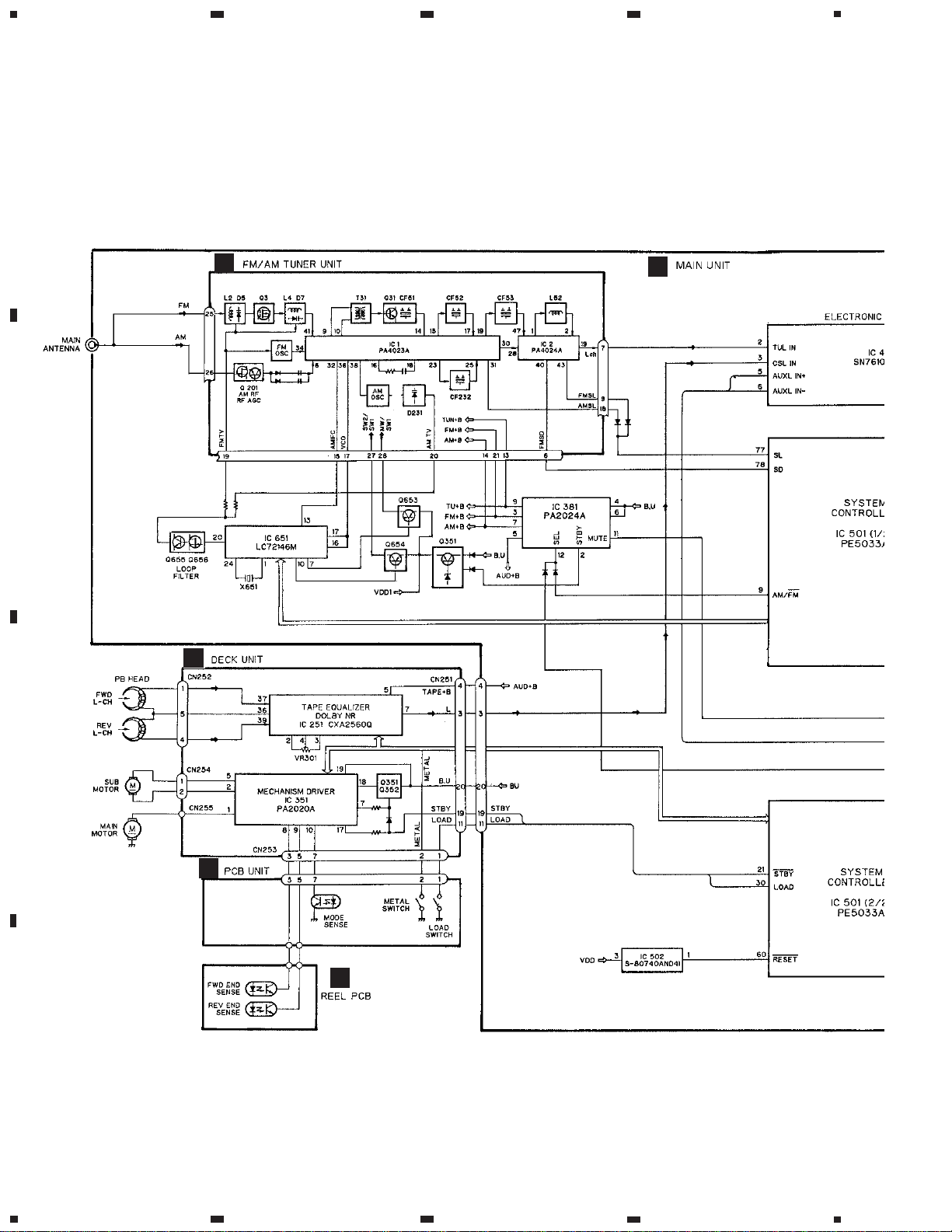
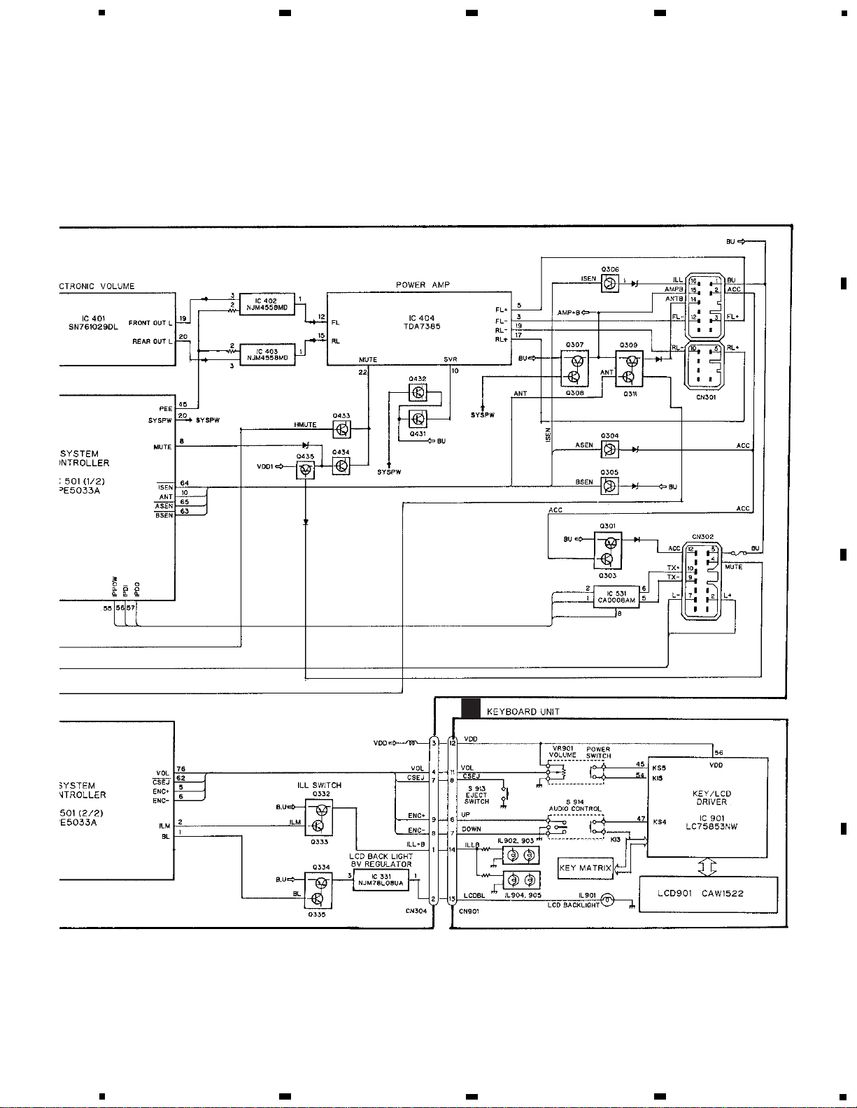
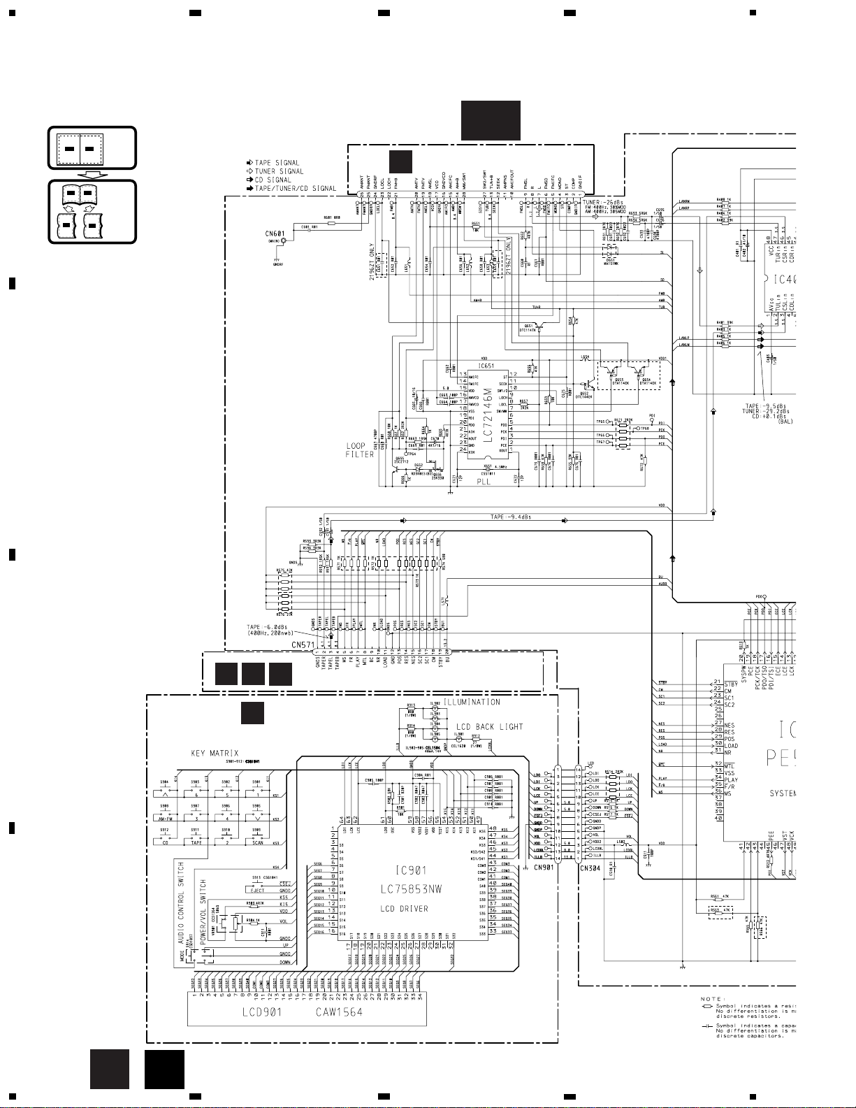
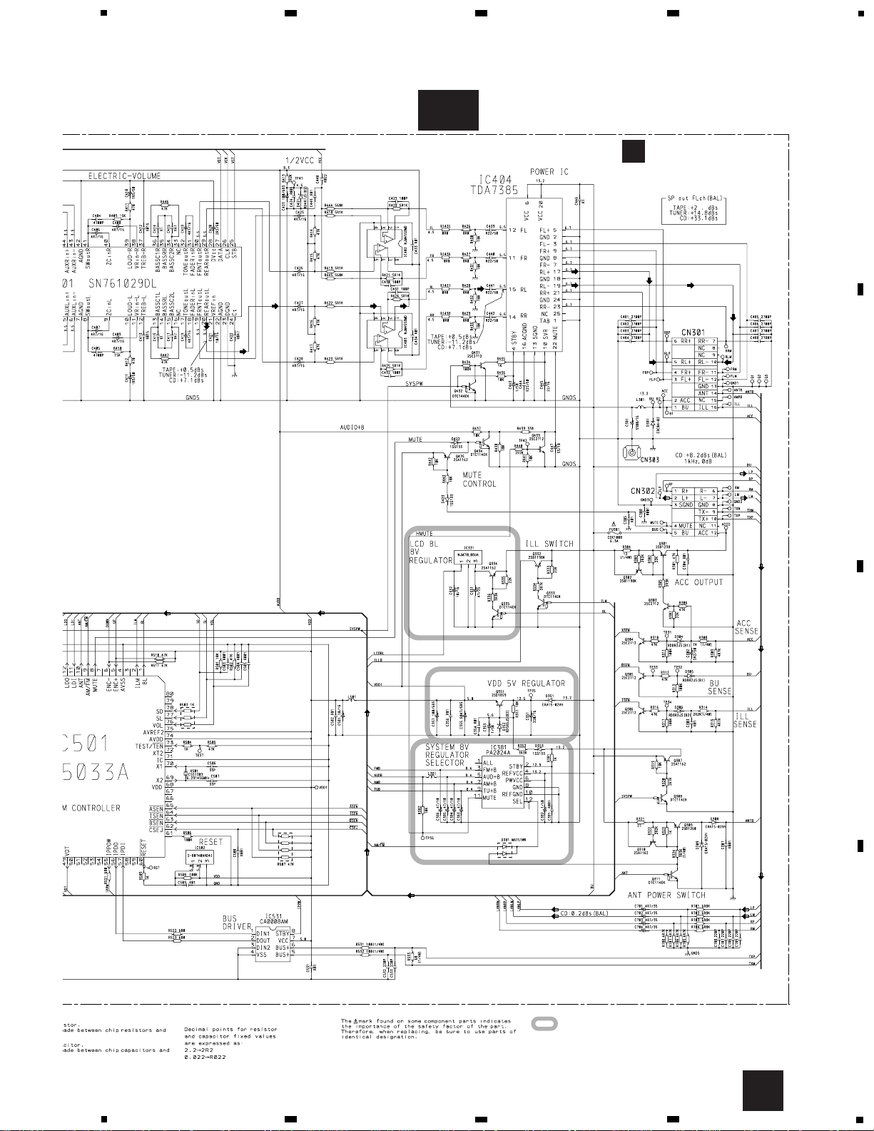
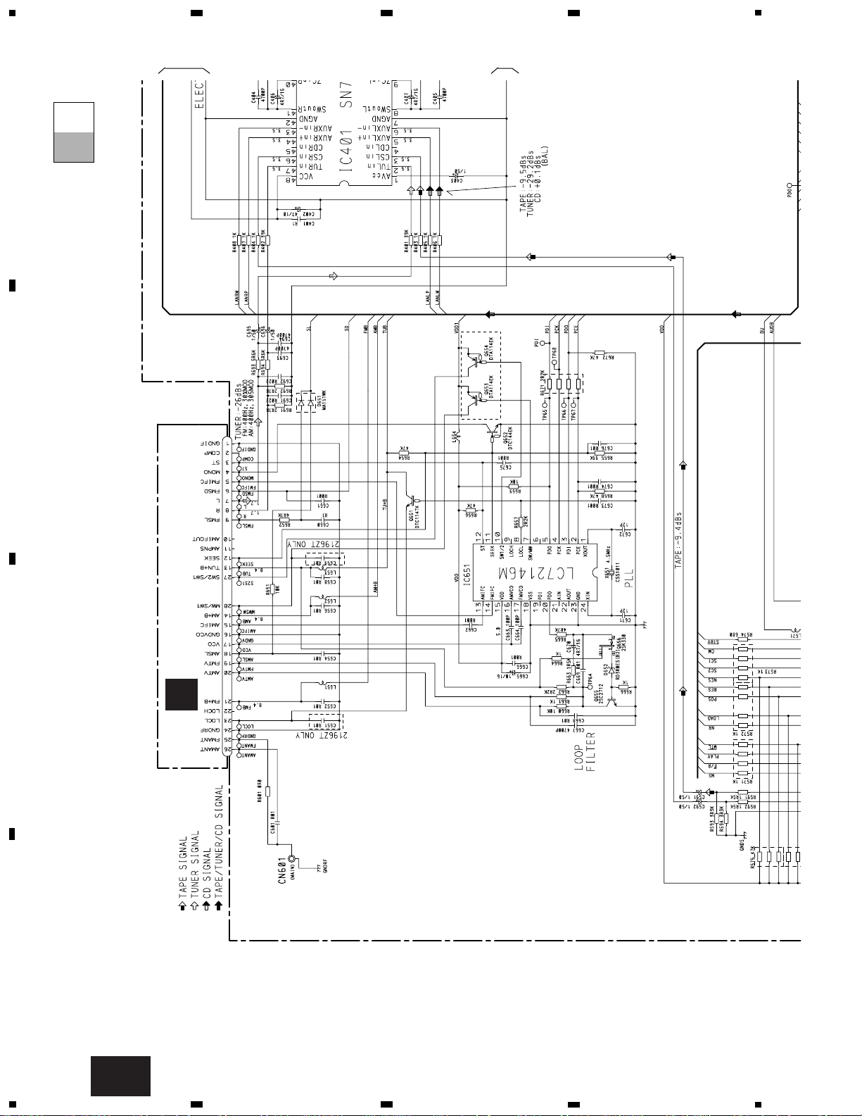
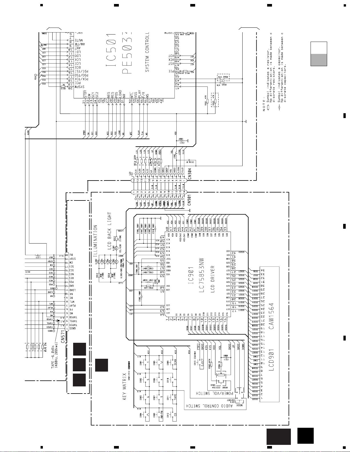
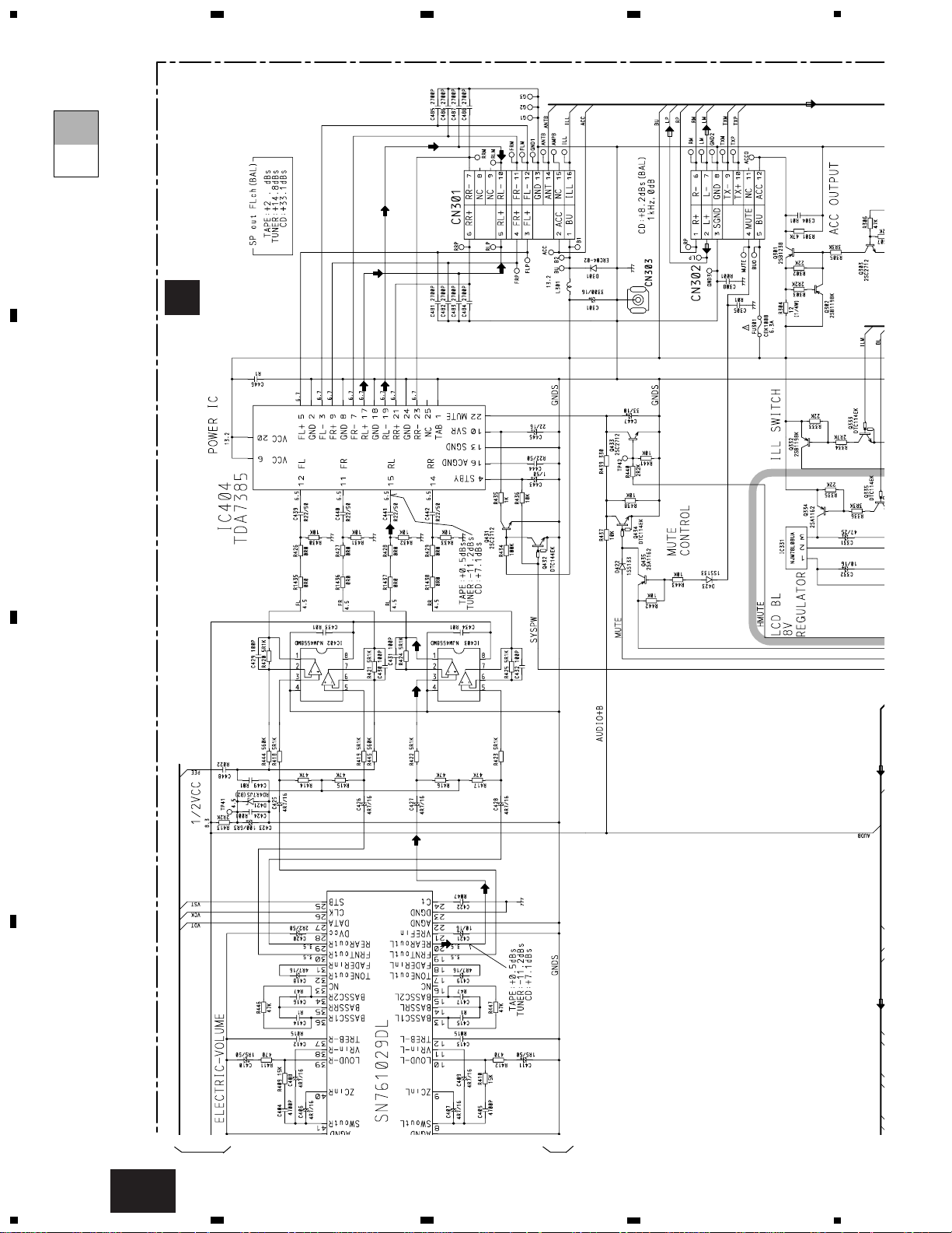
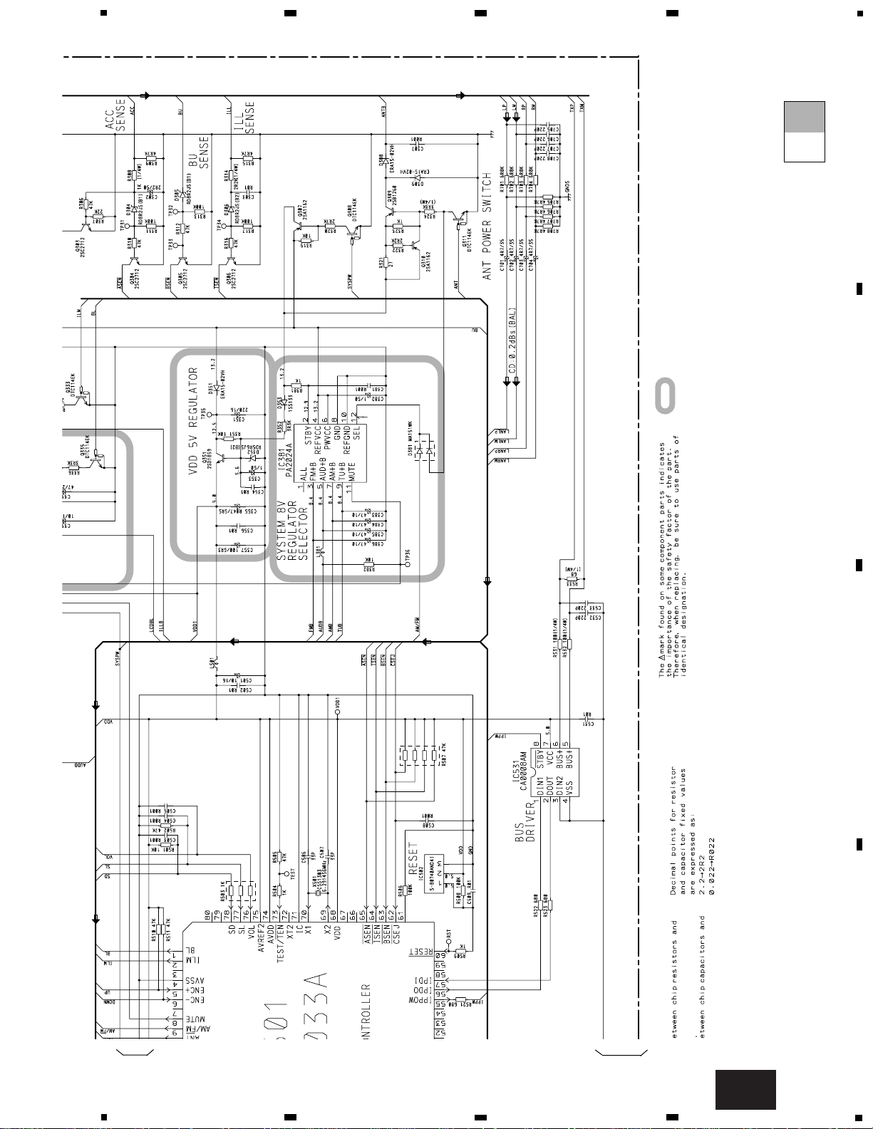
3. BLOCK DIAGRAM AND SCHEMATIC DIAGRAM
3.1 BLOCK DIAGRAM
A
B
D
E
F
Page 9
9
KEH-M2096ZT,M2196ZT
5
6
7
8
A
B
C
D
5
6
7
8
C
Page 10
MODEL
MODEL
MODEL
2096ZT ONLY
2196ZT ONLY
2196ZT ONLY
C
KEYBOARD UNIT
B
TUNER UNIT
F
CASSETTE MECHANISM MODULE
ED
ANTENNA JACK
10
KEH-M2096ZT,M2196ZT
A
1
234
B
C
D
12
34
A-a A-b
A-a
A-b
A-b
A-a
Large size
SCH diagram
Guide page
Detailed page
A
C
3.2 OVERALL CONNECTION DIAGRAM(GUIDE PAGE)
Note: When ordering service parts, be sure to refer to “EXPLODED VIEWS AND PARTS LIST” or “ELECTRICAL PARTS
LIST”.
A-a
Page 11
6
5
FM:0V
AM,SW:4.5V
TAPE,CD:11.5V
: The power supply is shown with the marked box.
A
MAIN UNIT
11
KEH-M2096ZT,M2196ZT
5
6
7
8
A
B
C
D
5
6
7
8
A-b
A
Page 12
12
KEH-M2096ZT,M2196ZT
A
1
234
B
C
D
12
34
2196ZT ONLY
B
TUNER UNIT
ANTENNA JACK
A-a
A-a
A-b
1
2
Page 13
13
KEH-M2096ZT,M2196ZT
5
6
7
8
A
B
C
D
5
6
7
8
MODEL
MODEL
MODEL
2096ZT ONLY
2196ZT ONLY
C
KEYBOARD UNIT
F
CASSETTE MECHANISM MODULE
ED
A-a
A-a
A-b
C
3
4
Page 14
14
KEH-M2096ZT,M2196ZT
A
1
234
B
C
D
12
34
6
5
A
MAIN UNIT
A-a
A-b
A-b
1
2
Page 15
15
KEH-M2096ZT,M2196ZT
5
6
7
8
A
B
C
D
5
6
7
8
FM:0V
AM,SW:4.5V
TAPE,CD:11.5V
: The power supply is shown with the marked box.
A-a
A-b
A-b
3
4
Page 16
16
KEH-M2096ZT,M2196ZT
A
1
234
B
C
D
12
34
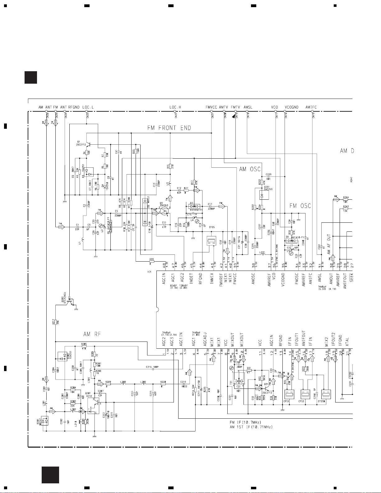
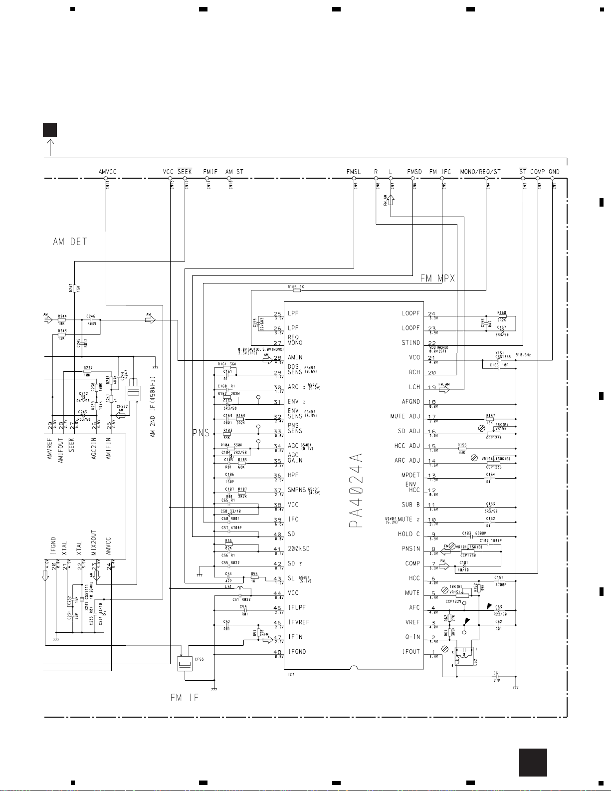
3.3 TUNER UNIT
B
- CWE1426 (KEH-M2096ZT/ES)
PA4023B
B
TUNER UNIT
Page 17
17
KEH-M2096ZT,M2196ZT
5
6
7
8
A
B
C
D
5
6
7
8
B
A
Page 18

18
KEH-M2096ZT,M2196ZT
A
1
234
B
C
D
12
34
B
- CWE1459 (KEH-M2196ZT/ES)
B
TUNER UNIT
Page 19

19
KEH-M2096ZT,M2196ZT
5
6
7
8
A
B
C
D
5
6
7
8
B
A
Page 20

Fwd-R
Fwd-L
Rev-R
Rev-L
20
KEH-M2096ZT,M2196ZT
A
1
234
B
C
D
12
34
3.4 CASSETTE MECHANISM MODULE
D
DECK UNIT
Page 21

21
KEH-M2096ZT,M2196ZT
5
6
7
8
A
B
C
D
5
6
7
8
.
EXA1499
EXA1382
SWITCHES:
PCB UNIT
S1:LOAD SWITCH..........EJECT-PLAY
S2:70µs SWITCH............ON-OFF
The underlined indicates the switch position.
E
PCB UNIT
F
REEL PCB
Page 22

22
KEH-M2096ZT,M2196ZT
A
1
234
B
C
D
12
34
A
Main
Antenna
Sub
Antenna
MAIN UNIT
4. PCB CONNECTION DIAGRAM
4.1 MAIN UNIT
NOTE FOR PCB DIAGRAMS
1. The parts mounted on this PCB
include all necessary parts for
several destination.
For further information for
respective destinations, be sure
to check with the schematic
diagram.
2. Viewpoint of PCB diagrams
Capacitor
Connector
P.C.Board
Chip Part
SIDE A
SIDE B
A
B
Page 23

23
KEH-M2096ZT,M2196ZT
5
6
7
8
A
B
C
D
5
6
7
8
CN901
D
A
CN251
C
SIDE A
Page 24

24
KEH-M2096ZT,M2196ZT
A
1
234
B
C
D
12
34
A
A
MAIN UNIT
Page 25

25
KEH-M2096ZT,M2196ZT
5
6
7
8
A
B
C
D
5
6
7
8
A
SIDE B
Page 26

26
KEH-M2096ZT,M2196ZT
A
1
234
B
C
D
12
34
4.2 TUNER UNIT
B
SIDE A
TUNER UNIT
A
B
Page 27

27
KEH-M2096ZT,M2196ZT
1
2
3
4
A
B
C
D
1
2
3
4
B
SIDE B
TUNER UNIT
B
Page 28

CD
AM.FM
TAPE
VOLUME
1
2
3
4
5
6 SCAN
AUDIO
CONTROL
EJECT
KEH-M2096ZT,M2196ZT
A
1
234
B
C
D
12
34
4.3 KEYBOARD UNIT
C
C
KEYBOARD UNIT
28
CN304
A
SIDE B
SIDE A
KEYBOARD UNIT
C
Page 29

A CN602
29
KEH-M2096ZT,M2196ZT
1
2
3
4
A
B
C
D
1
2
3
4
D
D
DECK UNIT
4.4 CASSETTE MECHANISM MODULE
CN571
IC,Q ADJ
VR302
IC351
IC251
Q351
Q352
VR301
HEAD
ASSY
E
M1
M2
E
A
SIDE A
SIDE B
DECK UNIT
D
Page 30

30
KEH-M2096ZT,M2196ZT
A
1
234
B
C
D
12
34
E
PCB UNIT
E
PCB UNIT
F
REEL PCB
FED
SIDE A
SIDE B
CN253
Page 31

31
KEH-M2096ZT,M2196ZT
D 651 Chip Diode MA151WK
D 652 Diode RD3R0ES(B2)
L 301 Coil CTH1191
L 381 Ferri-Inductor LAU4R7K
L 501 Ferri-Inductor LAU150K
L 502 Ferri-Inductor LAU150K
L 571 Inductor LFEA4R7J
L 651 Ferri-Inductor LAU4R7K
L 652 Ferri-Inductor LAU470K
L 653 Ferri-Inductor LAU4R7K
L 654 Ferri-Inductor LAU150K
X 501 Radiator 6.291456MHz CSS1303
X 651 Crystal Resonator 4.5MHz CSS1011
FU 301 Fuse 6.3A CEK1008
Tuner Unit(KEH-M2096ZT/ES) CWE1426
Tuner Unit(KEH-M2196ZT/ES CWE1459
RESISTORS
R 301 RS1/10S473J
R 302 RS1/10S223J
R 303 RS1/10S222J
R 304 RD1/4PU120J
R 305 RS1/10S332J
R 306 RS1/10S473J
R 307 RS1/10S223J
R 308 RD1/4PU102J
R 309 RS1/10S472J
R 310 RS1/10S473J
R 311 RS1/10S104J
R 312 RS1/10S473J
R 313 RS1/10S104J
R 314 RD1/4PU222J
R 315 RS1/10S472J
R 316 RS1/10S473J
R 317 RS1/10S104J
R 319 RS1/10S103J
R 320 RS1/10S272J
R 321 RS1/10S270J
R 322 RS1/10S222J
R 323 RS1/10S102J
R 324 RD1/4PU332J
R 333 RS1/10S223J
R 334 RS1/10S272J
R 335 RS1/10S223J
R 336 RS1/10S332J
R 351 RS1/10S103J
R 352 RS1/10S332J
R 381 RS1/10S102J
R 382 RS1/10S103J
R 401 RS1/10S393J
R 402 RS1/10S393J
R 403 RS1/10S102J
R 404 RS1/10S102J
5. ELECTRICAL PARTS LIST
NOTE:
- Parts whose parts numbers are omitted are subject to being not supplied.
- The part numbers shown below indicate chip components.
Chip Resistor
RS1/_S___J,RS1/__S___J
Chip Capacitor (except for CQS.....)
CKS....., CCS....., CSZS.....
Unit Number: CWM6480(KEH-M2096ZT/ES)
Unit Number: CWM6482(KEH-M2196ZT/ES)
Unit Name : Main Unit
MISCELLANEOUS
IC 331 IC NJM78L08UA
IC 381 IC PA2024A
IC 401 IC SN761029DL
IC 402 IC NJM4558MD
IC 403 IC NJM4558MD
IC 404 IC TDA7385
IC 501 IC PE5033A
IC 502 IC S-80740AND4I
IC 531 IC CA0008AM
IC 651 IC LC72146M
Q 301 Transistor 2SB1238
Q 302 Transistor 2SB1198K
Q 303 Chip Transistor 2SC2712
Q 304 Chip Transistor 2SC2712
Q 305 Chip Transistor 2SC2712
Q 306 Chip Transistor 2SC2712
Q 307 Transistor 2SA1162
Q 308 Transistor DTC114EK
Q 309 Transistor 2SB1260
Q 310 Transistor 2SA1162
Q 311 Transistor DTC114EK
Q 332 Transistor 2SB1198K
Q 333 Transistor DTC114EK
Q 334 Transistor 2SA1162
Q 335 Transistor DTC114EK
Q 351 Transistor 2SD1859
Q 431 Chip Transistor 2SC2712
Q 432 Transistor DTC144EK
Q 433 Chip Transistor 2SC2712
Q 434 Transistor DTC114EK
Q 435 Transistor 2SA1162
Q 651 Transistor DTC114TK
Q 652 Transistor DTC144EK
Q 653 Transistor(KEH-M2196ZT/ES) DTC144EK
Q 654 Transistor(KEH-M2196ZT/ES) DTC144EK
Q 655 Chip Transistor 2SC2712
Q 656 Transistor 2SK330
D 301 Diode ERC04-02
D 304 Diode RD8R2JS(B1)
D 305 Diode RD8R2JS(B1)
D 306 Diode RD8R2JS(B2)
D 308 Diode ERA15-02VH
D 309 Diode ERA15-02VH
D 351 Diode ERA15-02VH
D 352 Diode RD5R6JS(B2)
D 353 Diode 1SS133
D 381 Chip Diode MA151WK
D 421 Diode RD4R7JS(B2)
D 422 Diode 1SS133
D 423 Diode 1SS133
=====Circuit Symbol and No.===Part Name Part No.
--- ------ ------------------------------------------ -------------------------
=====Circuit Symbol and No.===Part Name Part No.
--- ------ ------------------------------------------ -------------------------
A
Page 32

32
KEH-M2096ZT,M2196ZT
R 405 RS1/10S102J
R 406 RS1/10S102J
R 407 RS1/10S102J
R 408 RS1/10S102J
R 409 RS1/10S153J
R 410 RS1/10S153J
R 411 RS1/10S471J
R 412 RS1/10S471J
R 413 RS1/10S222J
R 414 RS1/10S473J
R 415 RS1/10S473J
R 416 RS1/10S473J
R 417 RS1/10S473J
R 418 RS1/10S512J
R 419 RS1/10S512J
R 420 RS1/10S512J
R 421 RS1/10S512J
R 422 RS1/10S512J
R 423 RS1/10S512J
R 424 RS1/10S512J
R 425 RS1/10S512J
R 426 RS1/10S0R0J
R 427 RS1/10S0R0J
R 428 RS1/10S0R0J
R 429 RS1/10S0R0J
R 430 RS1/10S103J
R 431 RS1/10S103J
R 432 RS1/10S103J
R 433 RS1/10S103J
R 434 RS1/10S104J
R 435 RS1/10S102J
R 436 RS1/10S103J
R 437 RS1/10S103J
R 438 RS1/10S103J
R 439 RS1/10S331J
R 440 RS1/10S222J
R 441 RS1/10S103J
R 442 RS1/10S103J
R 443 RS1/10S103J
R 444 RS1/10S564J
R 445 RS1/10S564J
R 446 RS1/10S473J
R 447 RS1/10S473J
R 501 RS1/10S103J
R 502 RS1/10S473J
R 503 RA3C102J
R 504 RS1/10S102J
R 505 RS1/10S473J
R 506 RS1/10S104J
R 507 RA4C473J
R 508 RS1/10S104J
R 509 RS1/10S102J
R 510 RS1/10S473J
R 511 RS1/10S473J
R 512 RS1/10S472J
R 513 RS1/10S102J
R 514 RA4C222J
R 515 RS1/10S102J
R 516 RS1/10S102J
R 517 RS1/10S102J
R 521 RS1/10S681J
R 522 RS1/10S681J
R 523 RS1/10S681J
R 531 RD1/4PU101J
R 532 RD1/4PU101J
R 533 RD1/4PU680J
R 561 RS1/10S473J
R 563 (KEH-M2096ZT/ES) RS1/10S473J
R 565 RS1/10S473J
R 566 (KEH-M2196ZT/ES) RS1/10S473J
R 571 RA4C102J
R 572 RA4C102J
R 573 RA4C102J
R 574 RS1/10S681J
R 575 RA3C473J
R 576 RA3C273J
R 591 RS1/10S152J
R 592 RS1/10S152J
R 593 RS1/10S332J
R 594 RS1/10S332J
R 601 RS1/10S0R0J
R 651 RS1/10S103J
R 652 RS1/10S472J
R 654 RS1/10S473J
R 655 RS1/10S333J
R 656 RS1/10S473J
R 657 RS1/10S222J
R 658 RS1/10S473J
R 659 RS1/10S103J
R 660 RS1/10S103J
R 661 RS1/10S102J
R 662 RS1/10S222J
R 663 RS1/10S152J
R 664 RS1/10S102J
R 665 RS1/10S472J
R 666 RS1/10S102J
R 671 RA4C222J
R 672 RS1/10S473J
R 691 RS1/10S272J
R 692 RS1/10S272J
R 693 RS1/10S562J
R 694 RS1/10S562J
R 701 RS1/10S682J
R 702 RS1/10S682J
R 703 RS1/10S682J
R 704 RS1/10S682J
R 705 RS1/10S472J
R 706 RS1/10S472J
R 707 RS1/10S472J
R 708 RS1/10S472J
R 1435 RS1/8S0R0J
R 1436 RS1/8S0R0J
R 1437 RS1/8S0R0J
R 1438 RS1/8S0R0J
CAPACITORS
C 301 3300µF/16V CCH1177
C 302 CEJA2R2M50
C 303 CKSQYB103K50
C 304 CKSQYB103K50
C 305 CKSQYB103K50
C 307 CKSQYB102K50
C 308 CKSQYB102K50
C 331 CEJA470M25
C 332 CEJA100M16
C 351 CEAS221M16
C 353 CEJA1R0M50
C 354 CKSQYB103K50
C 355 0.047F/5.5V CCL1040
C 356 CKSQYB103K50
C 357 CEJA101M6R3
=====Circuit Symbol and No.===Part Name Part No.
--- ------ ------------------------------------------ -------------------------
=====Circuit Symbol and No.===Part Name Part No.
--- ------ ------------------------------------------ -------------------------
Page 33

33
KEH-M2096ZT,M2196ZT
C 381 CKSQYB102K50
C 382 CEJA1R0M50
C 383 CEAS470M10
C 384 CEAS470M10
C 385 CEAS470M10
C 386 CEAS470M10
C 401 CKSQYB104K16
C 402 CEJA470M10
C 403 CEJA1R0M50
C 404 CKSQYB472K50
C 405 CKSQYB472K50
C 406 CEJANP4R7M16
C 407 CEJANP4R7M16
C 408 CEJANP4R7M16
C 409 CEJANP4R7M16
C 410 CEJA1R5M50
C 411 CEJA1R5M50
C 412 CKSQYB153K25
C 413 CKSQYB153K25
C 414 CKSQYB104K16
C 415 CKSQYB104K16
C 416 CKSQYB474K16
C 417 CKSQYB474K16
C 418 CEJANP4R7M16
C 419 CEJANP4R7M16
C 420 CEJA2R2M50
C 421 CEJA100M16
C 422 CKSQYB473K16
C 423 CEJA101M6R3
C 424 CKSQYB102K50
C 425 CEJANP4R7M16
C 426 CEJANP4R7M16
C 427 CEJANP4R7M16
C 428 CEJANP4R7M16
C 429 CCSQCH101J50
C 430 CCSQCH101J50
C 431 CCSQCH101J50
C 432 CCSQCH101J50
C 433 CKSQYB103K50
C 434 CKSQYB103K50
C 439 CFTLA224J50
C 440 CFTLA224J50
C 441 CFTNA224J50
C 442 CFTNA224J50
C 443 CEHAS1R0M50
C 444 CFTNA224J50
C 445 CEHAS220M16
C 446 CKSQYB104K16
C 447 CEJA330M10
C 448 CKSQYB223K25
C 449 CKSQYB103K50
C 481 CKSQYB272K50
C 482 CKSQYB272K50
C 483 CKSQYB272K50
C 484 CKSQYB272K50
C 485 CKSQYB272K50
C 486 CKSQYB272K50
C 487 CKSQYB272K50
C 488 CKSQYB272K50
C 501 CEJA100M16
C 502 CKSQYB103K50
C 503 CKSQYB102K50
C 504 CKSQYB102K50
C 505 CKSQYB102K50
C 506 CCSQCH330J50
C 507 CCSQCH330J50
C 508 CKSQYB102K50
C 509 CKSQYB103K50
C 510 CKSQYB104K16
C 511 CCSQCH101J50
C 531 CKSQYB103K50
C 532 CKSQYB221K50
C 533 CKSQYB221K50
C 591 CEJA1R0M50
C 592 CEJA1R0M50
C 601 CKSYB103K50
C 651 (KEH-M2196ZT/ES) CKSQYB103K50
C 652 CKSQYB103K50
C 654 CKSQYB103K50
C 656 CKSQYB103K50
C 658 CKSQYB103K50
C 659 (KEH-M2196ZT/ES) CKSQYB103K50
C 660 CKSQYB104K16
C 661 CKSQYB102K50
C 662 CKSQYB102K50
C 663 CCSQCH101J50
C 664 CCSQCH101J50
C 665 CEJA100M16
C 666 CKSQYB102K50
C 667 CKSQYB472K50
C 668 CGCYX103K25
C 669 CKSQYB103K50
C 670 4.7µF/16V CCH1165
C 671 CCSQCH120J50
C 672 CCSQCH120J50
C 673 CKSQYB102K50
C 674 CKSQYB102K50
C 675 CKSQYB102K50
C 676 CKSQYB103K50
C 691 CKSQYB223K25
C 692 CKSQYB223K25
C 693 CKSQYB472K50
C 694 CKSQYB472K50
C 695 CEJA1R0M50
C 696 CEJA1R0M50
C 701 CEJA4R7M35
C 702 CEJA4R7M35
C 703 CEJA4R7M35
C 704 CEJA4R7M35
C 705 CKSQYB221K50
C 706 CKSQYB221K50
C 707 CKSQYB221K50
C 708 CKSQYB221K50
Unit Number: CWM6481
Unit Name : Keyboard Unit
MISCELLANEOUS
IC 901 IC LC75853NW
S 901 Switch CSG1041
S 902 Switch CSG1041
S 903 Switch CSG1041
S 904 Switch CSG1041
S 905 Switch CSG1041
S 906 Switch CSG1041
S 907 Switch CSG1041
S 908 Switch CSG1041
S 909 Switch CSG1041
S 910 Switch CSG1041
S 911 Switch CSG1041
S 912 Switch CSG1041
S 913 Switch CSG1041
S 914 Switch CSD1037
IL 901 Lamp CEL1620
IL 902 Lamp 40mA 14V CEL1504
IL 903 Lamp 40mA 14V CEL1504
IL 904 Lamp 40mA 14V CEL1504
IL 905 Lamp 40mA 14V CEL1504
VR 901 Volume 50kΩ(B) CCS1264
LCD 901 LCD CAW1564
=====Circuit Symbol and No.===Part Name Part No.
--- ------ ------------------------------------------ -------------------------
=====Circuit Symbol and No.===Part Name Part No.
--- ------ ------------------------------------------ -------------------------
C
Page 34

34
KEH-M2096ZT,M2196ZT
=====Circuit Symbol and No.===Part Name Part No.
--- ------ ------------------------------------------ -------------------------
=====Circuit Symbol and No.===Part Name Part No.
--- ------ ------------------------------------------ -------------------------
RESISTORS
R 901 RS1/16S103J
R 902 RS1/16S683J
R 903 RS1/10S472J
R 904 RS1/10S102J
R 912 RS1/8S270J
R 913 RS1/8S0R0J
R 914 RS1/8S0R0J
CAPACITORS
C 901 CKSRYB821K50
C 902 CKSRYB473K16
C 903 CKSRYB473K16
C 904 CKSRYB103K50
C 905 CCSRCH101J50
C 906 CKSRYB102K50
C 907 CKSRYB102K50
C 908 CKSRYB102K50
C 909 CKSRYB102K50
C 910 CKSRYB102K50
C 911 CKSQYB102K50
Unit Number : CWE1426(KEH-M2096ZT/ES)
Unit Name : Tuner Unit
MISCELLANEOUS
IC 1 IC PA4023B
IC 2 IC PA4024A
Q 1 Transistor 2SC2712
Q 3 FET 3SK263
Q 31 Transistor 2SC2712
Q 201 Transistor FC12
Q 203 Transistor DTC124EU
D 3 Diode 1SV251
D 4 Diode 1SV250
D 5 Diode KV1410-F1
D 6 Diode MA157
D 7 Diode KV1410-F1
D 8 Diode KV1410-F1
D 201 Diode MA157
D 202 Diode 1SV251
D 231 Diode SVC253
L 1 Inductor LCTBR12K2125
L 2 Coil CTC1145
L 3 Inductor LCTB4R7K2125
L 4 Coil CTC1131
L 5 Coil CTC1147
L 51 Ferri-Inductor LAU150K
L 52 Coil CTC1136
L 201 Ferri-Inductor LAU4R7K
L 202 Ferri-Inductor LAU330K
L 203 Inductor CTF1371
L 208 Inductor LAU390K
L 209 Ferri-Inductor LAU680K
L 210 Coil CTB1103
L 231 Inductor LAU3R3J
T 31 Coil CTE1116
CF 25 Ceramic Filter CTF1290
CF 51 Ceramic Filter CTF1290
CF 52 Ceramic Filter CTF1290
CF 53 Ceramic Filter CTF1290
CF 230 Crystal Filter CTF1262
CF 232 Ceramic Filter CTF1348
X 151 Resonator 918.5Hz CSS1365
X 231 Crystal Resonator 10.26MHz CSS1111
VR 101 Semi-fixed 15kΩ(B) CCP1230
VR 151 Semi-fixed 10kΩ(B) CCP1229
VR 154 Semi-fixed 150kΩ(B) CCP1236
VR 156 Semi-fixed 68kΩ(B) CCP1234
AR 1 Surge Protector DSP-201M
RESISTORS
R 3 RS1/16S223J
R 4 RS1/16S101J
R 5 RS1/16S181J
R 6 RS1/16S101J
R 7 RS1/10S331J
R 8 RS1/16S473J
R 9 RS1/16S473J
R 10 RS1/16S223J
R 11 RS1/16S124J
R 12 RS1/16S474J
R 15 RS1/16S271J
R 16 RS1/16S104J
R 17 RS1/16S473J
R 18 RS1/16S473J
R 19 RS1/16S154J
R 27 RS1/16S0R0J
R 31 RS1/16S470J
R 32 RS1/16S912J
R 33 RS1/16S912J
R 34 RS1/16S331J
R 35 RS1/16S331J
R 39 RS1/16S0R0J
R 51 RS1/16S331J
R 55 RS1/16S102J
R 56 RS1/16S823J
R 61 RS1/16S392J
R 62 RS1/16S273J
R 103 RS1/16S333J
R 104 RS1/16S334J
R 105 RS1/16S683J
R 107 RS1/16S222J
R 152 RS1/16S393J
R 155 RS1/16S563J
R 157 RS1/10S183J
R 160 RS1/16S222J
R 161 RS1/16S563J
R 162 RS1/16S225J
R 163 RS1/16S222J
R 165 RS1/16S102J
R 202 RS1/16S223J
R 203 RS1/16S225J
R 204 RS1/16S103J
R 205 RS1/16S471J
R 206 RS1/16S220J
R 207 RS1/16S101J
R 208 RS1/16S102J
R 209 RS1/16S0R0J
R 214 RS1/16S563J
R 215 RS1/16S473J
R 217 RS1/16S393J
R 220 RS1/10S0R0J
R 231 RS1/16S242J
R 232 RS1/16S473J
R 233 RS1/16S0R0J
R 234 RS1/16S0R0J
R 237 RS1/16S103J
R 238 RS1/16S104J
R 239 RS1/16S104J
R 240 RS1/16S472J
R 241 RS1/16S202J
B
Page 35

35
KEH-M2096ZT,M2196ZT
R 243 RS1/16S123J
R 244 RS1/16S103J
R 247 RS1/10S153J
CAPACITORS
C 1 CCSRCH220J50
C 2 CKSRYB222K50
C 3 CCSRCH6R0D50
C 5 CKSRYB222K50
C 6 CKSQYB473K16
C 7 CKSQYB473K16
C 8 CKSQYB104K16
C 9 CCSRCJ3R0C50
C 10 CEJA1R0M50
C 11 CCSRCH470J50
C 12 CCSRCH820J50
C 13 CKSRYB222K50
C 14 CCSRCH4R0C50
C 15 CCSRCH7R0D50
C 16 CCSRCH120J50
C 17 CKSRYB222K50
C 18 CKSRYB103K25
C 19 CKSRYB222K50
C 20 CKSRYB222K50
C 21 CEJA100M16
C 22 CCSRRH100D50
C 23 CCSRRH120J50
C 24 CKSRYB103K25
C 30 CCSRRH201J50
C 31 CKSRYB103K25
C 32 CKSQYB473K16
C 33 CCSRCK2R0C50
C 35 CCSRCH270J50
C 36 CCSRCH120J50
C 40 CKSRYB222K50
C 41 CKSQYB104K16
C 51 CKSRYB223K25
C 52 CKSRYB103K25
C 54 CCSRCH470J50
C 55 CKSQYB223K25
C 56 CKSQYB104K16
C 57 CKSRYB472K50
C 58 CEJA330M10
C 59 CKSRYB103K25
C 60 CKSRYB102K50
C 61 CCSRCH270J50
C 62 CKSRYB103K25
C 63 CEJAR22M50
C 65 CKSQYB104K16
C 101 CEJANP100M10
C 102 CKSRYB182K50
C 103 CKSQYB682K50
C 104 CEJA2R2M50
C 105 CKSRYB103K25
C 106 CCSRCH151J50
C 107 CKSRYB103K25
C 151 CKSRYB472K50
C 152 CKSQYB104K16
C 153 CEJA3R3M50
C 154 CKSQYB104K16
C 157 CEJA3R3M50
C 158 CKSYB474K16
C 159 CEJA220M6R3
C 160 CKSQYB104K16
C 161 CKSQYB104K16
C 162 CEJA3R3M50
C 163 CKSRYB102K50
C 165 CCSRCH100D50
C 201 CKSRYB103K25
C 202 CCSRCH100D50
C 203 CKSRYB332K50
C 204 CKSQYB473K16
C 205 CKSQYB473K16
C 206 CKSQYB103K25
C 207 CCSRCH120J50
C 211 CCSRCH560J50
C 212 CEJA101M10
C 213 CKSRYB103K25
C 215 CCSRCH680J50
C 216 CCSRCH101J50
C 217 CEJAR47M50
C 219 CKSRYB223K25
C 220 CKSRYB103K25
C 221 CKSRYB103K25
C 230 CKSQYB104K16
C 231 CCSRCH330J50
C 232 CCSRCH150J50
C 233 CKSRYB103K25
C 234 CEJA330M10
C 235 CKSRYB332K50
C 236 CKSQYB473K16
C 237 CCSRTH180J50
C 239 CKSRYB103K25
C 240 CKSYB104K16
C 241 CKSQYB104K16
C 242 CEJAR47M50
C 243 CEJAR33M50
C 244 CKSQYB473K16
C 245 CKSQYB123K25
C 246 CKSQYB393K25
C 250 CCSRCJ3R0C50
Unit Number: CWE1459(KEH-M2196ZT/ES)
Unit Name : Tuner Unit
MISCELLANEOUS
IC 1 IC PA4023B
IC 2 IC PA4024A
Q 1 Transistor 2SC2712
Q 3 FET 3SK263
Q 31 Transistor 2SC2712
Q 201 Transistor FC12
Q 203 Transistor DTC124EU
Q 204 Transistor DTC124EU
Q 205 Transistor DTC124EU
Q 206 Transistor 2SC4116
Q 231 Transistor 2SC4116
D 3 Diode 1SV251
D 4 Diode 1SV250
D 5 Diode KV1410-F1
D 6 Diode MA157
D 7 Diode KV1410-F1
D 8 Diode KV1410-F1
D 201 Diode MA157
D 202 Diode 1SV251
D 203 Diode MA141WA
D 204 Diode MA110
D 205 Diode MA110
D 231 Diode KV1590(12)
L 1 Inductor LCTBR12K2125
L 2 Coil CTC1145
=====Circuit Symbol and No.===Part Name Part No.
--- ------ ------------------------------------------ -------------------------
=====Circuit Symbol and No.===Part Name Part No.
--- ------ ------------------------------------------ -------------------------
B
Page 36

36
KEH-M2096ZT,M2196ZT
L 3 Inductor LCTB4R7K2125
L 4 Coil CTC1131
L 5 Coil CTC1147
L 51 Ferri-Inductor LAU150K
L 52 Coil CTC1136
L 201 Inductor LAU3R3K
L 202 Ferri-Inductor LAU4R7K
L 203 Inductor CTF1371
L 205 Inductor LCTB3R3K2125
L 206 Inductor LCTB4R7K2125
L 207 Inductor LCTB120K2125
L 208 Inductor LAU180K
L 209 Inductor LAU120K
L 210 Coil CTB1103
T 31 Coil CTE1116
T 231 Coil CTB1106
CF 25 Ceramic Filter CTF1290
CF 51 Ceramic Filter CTF1290
CF 52 Ceramic Filter CTF1290
CF 53 Ceramic Filter CTF1290
CF 230 Crystal Filter CTF1262
CF 232 Ceramic Filter CTF1348
X 151 Resonator 918.5Hz CSS1365
X 231 Crystal Resonator 10.26MHz CSS1111
VR 101 Semi-fixed 15kΩ(B) CCP1230
VR 151 Semi-fixed 15kΩ(B) CCP1229
VR 154 Semi-fixed 150kΩ(B) CCP1236
VR 156 Semi-fixed 68kΩ(B) CCP1234
AR 1 Surge Protector DSP-201M
RESISTORS
R 3 RS1/16S223J
R 4 RS1/16S101J
R 5 RS1/16S181J
R 6 RS1/16S101J
R 7 RS1/10S331J
R 8 RS1/16S473J
R 9 RS1/16S473J
R 10 RS1/16S223J
R 11 RS1/16S124J
R 12 RS1/16S474J
R 15 RS1/16S271J
R 16 RS1/16S104J
R 17 RS1/16S473J
R 18 RS1/16S473J
R 19 RS1/16S154J
R 27 RS1/16S0R0J
R 31 RS1/16S470J
R 32 RS1/16S912J
R 33 RS1/16S912J
R 34 RS1/16S331J
R 35 RS1/16S331J
R 39 RS1/16S0R0J
R 51 RS1/16S331J
R 55 RS1/16S102J
R 56 RS1/16S823J
R 61 RS1/16S392J
R 62 RS1/16S273J
R 103 RS1/16S333J
R 104 RS1/16S334J
R 105 RS1/16S683J
R 107 RS1/16S222J
R 152 RS1/16S393J
R 155 RS1/16S563J
R 157 RS1/10S203J
R 160 RS1/16S222J
R 161 RS1/16S563J
R 162 RS1/16S225J
R 163 RS1/16S222J
R 165 RS1/16S102J
R 201 RS1/16S471J
R 202 RS1/16S182J
R 204 RS1/16S103J
R 205 RS1/16S471J
R 206 RS1/16S220J
R 207 RS1/16S162J
R 208 RS1/16S0R0J
R 210 RS1/16S104J
R 211 RS1/16S103J
R 212 RS1/16S104J
R 213 RS1/16S103J
R 214 RS1/16S563J
R 215 RS1/16S473J
R 216 RS1/16S104J
R 217 RS1/16S393J
R 231 RS1/16S242J
R 232 RS1/16S473J
R 234 RS1/16S473J
R 235 RS1/16S472J
R 237 RS1/16S103J
R 238 RS1/16S104J
R 239 RS1/16S104J
R 240 RS1/16S472J
R 241 RS1/16S202J
R 243 RS1/16S123J
R 244 RS1/16S103J
R 247 RS1/10S153J
R 248 RS1/16S473J
R 249 RS1/16S0R0J
CAPACITORS
C 1 CCSRCH220J50
C 2 CKSRYB222K50
C 3 CCSRCH6R0D50
C 5 CKSRYB222K50
C 6 CKSQYB473K16
C 7 CKSQYB473K16
C 8 CKSQYB104K16
C 9 CCSRCJ3R0C50
C 10 CEJA1R0M50
C 11 CCSRCH470J50
C 12 CCSRCH820J50
C 13 CKSRYB222K50
C 14 CCSRCH4R0C50
C 15 CCSRCH7R0D50
C 16 CCSRCH120J50
C 17 CKSRYB222K50
C 18 CKSRYB103K25
C 19 CKSRYB222K50
C 20 CKSRYB222K50
C 21 CEJA100M16
C 22 CCSRRH100D50
C 23 CCSRRH120J50
C 24 CKSRYB103K25
C 30 CCSRRH201J50
C 31 CKSRYB103K25
C 32 CKSQYB473K16
C 33 CCSRCK2R0C50
C 35 CCSRCH270J50
C 36 CCSRCH120J50
C 40 CKSRYB222K50
=====Circuit Symbol and No.===Part Name Part No.
--- ------ ------------------------------------------ -------------------------
=====Circuit Symbol and No.===Part Name Part No.
--- ------ ------------------------------------------ -------------------------
Page 37

37
KEH-M2096ZT,M2196ZT
C 41 CKSQYB104K16
C 51 CKSRYB223K25
C 52 CKSRYB103K25
C 54 CCSRCH470J50
C 55 CKSQYB223K25
C 56 CKSQYB104K16
C 57 CKSRYB472K50
C 58 CEJA330M10
C 59 CKSRYB103K25
C 60 CKSRYB102K50
C 61 CCSRCH270J50
C 62 CKSRYB103K25
C 63 CEJAR22M50
C 65 CKSQYB104K16
C 101 CEJANP100M10
C 102 CKSRYB182K50
C 103 CKSQYB682K50
C 104 CEJA2R2M50
C 105 CKSRYB103K25
C 106 CCSRCH151J50
C 107 CKSRYB103K25
C 151 CKSRYB472K50
C 152 CKSQYB104K16
C 153 CEJA3R3M50
C 154 CKSQYB104K16
C 157 CEJA3R3M50
C 158 CKSYB474K16
C 159 CEJA220M6R3
C 160 CKSQYB104K16
C 161 CKSQYB104K16
C 162 CEJA3R3M50
C 163 CKSRYB102K50
C 165 CCSRCH100D50
C 201 CKSRYB103K25
C 202 CCSRCH180J50
C 203 CKSRYB332K50
C 204 CKSQYB473K16
C 205 CKSQYB473K16
C 206 CKSQYB103K25
C 207 CCSRCH120J50
C 208 CCSRCH180J50
C 209 CCSRCH470J50
C 210 CCSRCH470J50
C 211 CCSRCH270J50
C 212 CEJA101M10
C 213 CKSRYB103K25
C 215 CCSRCH470J50
C 216 CCSRCH100D50
C 217 CEJAR47M50
C 218 CKSRYB102K50
C 219 CCSRCH101J50
C 220 CKSRYB103K25
C 221 CKSRYB103K25
C 222 CCSRCH180J50
C 230 CKSQYB104K16
C 231 CCSRCH330J50
C 232 CCSRCH150J50
C 233 CKSRYB103K25
C 234 CEJA330M10
C 235 CKSRYB332K50
C 236 CKSQYB473K16
C 237 CCSRCH8R0D50
C 238 CCSRCH181J50
C 239 CKSRYB103K25
C 240 CKLSR104K16
C 241 CKSQYB104K16
C 242 CEJAR47M50
C 243 CEJAR33M50
C 244 CKSQYB473K16
C 245 CKSQYB123K25
C 246 CKSQYB393K25
C 250 CCSRCJ3R0C50
Unit Number : EWM1016
Unit Name : Deck Unit
MISCELLANEOUS
IC 251 IC CXA2560Q
IC 351 IC PA2020A
Q 351 Transistor 2SB1260
Q 352 Transistor 2SC4102
D 351 Diode 1SS355
VR 301 Semi-fixed 33kΩ(B) CCP1280
VR 302 Semi-fixed 33kΩ(B) CCP1280
RESISTORS
R 255 RS1/16S221J
R 256 RS1/16S221J
R 257 RS1/16S102J
R 258 RS1/16S102J
R 271 RS1/16S102J
R 272 RS1/16S102J
R 273 RS1/16S102J
R 281 RS1/8S0R0J
R 282 RS1/8S0R0J
R 283 RS1/8S0R0J
R 284 RS1/8S0R0J
R 285 RS1/16S0R0J
R 286 RS1/16S0R0J
R 287 RS1/8S0R0J
R 290 RS1/8S0R0J
R 301 RS1/16S183J
R 322 RS1/16S102J
R 351 RS1/16S102J
R 352 RS1/16S102J
R 353 RS1/16S102J
R 354 RS1/16S102J
R 355 RS1/10S274J
R 356 RS1/10S202J
R 357 RS1/10S472J
R 358 RS1/10S103J
R 359 RS1/10S103J
R 360 RS1/10S102J
R 361 RS1/10S622J
R 362 RS1/8S181J
R 373 RS1/8S0R0J
R 374 RS1/8S0R0J
R 375 RS1/8S0R0J
R 401 RS1/16S472J
R 402 RS1/16S163J
R 403 RS1/16S823J
CAPACITORS
C 251 CKSRYB331K50
C 252 CKSRYB331K50
C 253 CKSRYB331K50
C 254 CKSRYB331K50
C 255 CKSRYB103K25
C 256 CKSRYB103K25
C 272 CKSQYB104K16
C 273 CEJA220M16
C 301 CKSYB104K50
C 302 CKSYB104K50
=====Circuit Symbol and No.===Part Name Part No.
--- ------ ------------------------------------------ -------------------------
=====Circuit Symbol and No.===Part Name Part No.
--- ------ ------------------------------------------ -------------------------
D
Page 38

38
KEH-M2096ZT,M2196ZT
C 309 CKSQYB104K16
C 310 CKSQYB104K16
C 313 CCSQCH101K50
C 351 CKSYB224K25
C 352 CKSQYB392K50
C 353 CKSQYB103K50
C 354 CKSQYB103K50
C 355 CKSYB104K50
C 356 CKSQYB103K50
C 401 CKSQYB334K16
C 402 CKSQYB472K50
C 403 CKSQYB683K16
Unit Number :
Unit Name : PCB Unit
S 1 Switch(LOAD) ESG1004
S 2 Switch(70µS) ESG1004
EGN 1 Photo-Interrupter EGN1005
Unit Number :
Unit Name : Reel PCB
EGN 2 Photo-Interrupter EGN1006
EGN 3 Photo-Interrupter EGN1006
MISCELLANEOUS
M 1 Motor Unit(MAIN) EXA1499
M 2 Motor Unit(SUB) EXA1382
HD 1 Head Assy EXA1506
=====Circuit Symbol and No.===Part Name Part No.
--- ------ ------------------------------------------ -------------------------
E
F
Page 39

39
KEH-M2096ZT,M2196ZT
FM SSG
Stereo
Modulator
50Ω(37.5Ω)
Antenna Plug
Dummy Antenna
50Ω(75Ω)
MAIN UNIT
TUNER UNIT
4kΩ
4kΩ
+13.2V
Antenna
Jack (Main)
mV Meter (1)
Oscilloscope
DC Regulated
Power Supply
DECK UNIT
DC V
Meter(1)
Center
Meter
Pin 19
TUNER UNIT (BOTTOM VIEW)
C63
TUNER UNIT (TOP VIEW)
L2
L5
T31
Pin1
Pin13
Pin14
Pin26
L4
VR156
DECK UNIT
RR–
RR+
RL+
RL–
GND
ACC
VR154
VR101
L52
VR151
BUP
VR301
VR302
CN251
Pin2
Pin3
R-CHL-CH
GGD1019
mV
Meter(2)
T231
DC V
Meter(2)
Pin 6
DC V
Meter(3)
Pin 20
L52
6. ADJUSTMENT
- Connection Diagram
Page 40

40
KEH-M2096ZT,M2196ZT
FM ADJUSTMENT
NOTE:Before proceeding to further adjustments after switching power ON, let the tuner run for ten minutes to allow
the circuits to stabilize.
Modulation M : MONO MOD., 400Hz, 30%(22.5kHz Dev.)
S : STEREO MOD., 1kHz, L or R=30%(20.25+7.5kHz Dev.)
FM SSG Displayed Adjustment Adjustment Method
No. Frequency(MHz) Level(dBf) Frequency(MHz) Point (Switch Position)
TUN Volt 1 ••••• ••••• 108.0 L5 DC V Meter(1) : 6.5V
Center 1 98.1 M 65-85 98.1 L52 Center Meter : 0
ANT 1 89.9 M 5-15 89.9 L2 mV Meter(1) : Maximum
RF 1 89.9 M 5-15 89.9 L4 mV Meter(1) : Maximum
IFT 1 98.1 M 5-15 98.1 T31 mV Meter(1) : Maximum
(STEREO MODE)
Sepa- 1 98.1 S 65 98.1 VR101 mV Meter(1) : Separation
ration Maximum
ARC 1 98.1 S 40 98.1 VR154 mV Meter(1) : Separation 5dB
Inter- 1 98.1 M 65 98.1 ••••• mV Meter(1) : AdB
station 2 98.1 M -∞ 98.1 VR151 mV Meter(1) : -20dB
Noise
(STEREO MODE)
Search 1 98.1 M 27 98.1 VR156 DC V Meter(2) : More than 3.5V
(STEREO MODE)
SW2 ADJUSTMENT (KEH-M2196ZT/ES)
AM SSG Displayed Adjustment Adjustment Method
No. Frequency(MHz) Level(dBf) Frequency(MHz) Point (Switch Position)
TUN Volt 1 ••••• ••••• 21.975 T231 DC V Meter(3) : 6.0V
DOLBY B NR ADJUSTMENT
No. Test Tape Adjustment Point Adjustment Method
(Switch Position)
1 ACT-150 VR301(Lch),VR302(Rch) mV Meter(2) : –6dBs±1dB
(400Hz,200nwb/m) (DOLBY NR Switch : OFF)
Page 41

41
KEH-M2096ZT,M2196ZT
7. GENERAL INFORMATION
7.1 DIAGNOSIS
7.1.1 TEST MODE
Test mode is to be operated only when AVC-LAN CD changer is connected to this product.
- Flow Chart
1
CD player select
RPT
Display
<Regulator OFF>
Carriage shifted
inwards while
this key is pressed
<Close spindle>
(Rough)
CD
Carriage move
or T. jump
6
TRACK
RPT
SCAN
SCAN
SCAN
SCAN
SCAN
RAND
RPT
<Close focus>
Power
OFF
AGC
AGC display
select
*1
Carriage move
or T. jump
*5
*3
*2
Display
<Regulator ON>
Regulator ON
Power
OFF
Power
OFF
Power
OFF
Display
Display
example
Carriage shifted
outwards while
this key is pressed
<Close tracking>
Carriage shifted
inwards while
this key is pressed
Carriage shifted
outwards while
this key is pressed
Press the [CD] key three times,
while holding down the [1] and
[6] keys simultaneously.Diagnosis mode
*2
Normal focus close 00 only.
*3
Normal display Focus gain Track gain
*5
In the case of 100TRK jump and C.MOVE mode only.
*1
Press the DISP Key for change the display.
CD test mode
Press the [TRACK ] and [CD]
keys simultaneously.
CD
1-01
CD
1'50
*1
CD
1-11
CD
11'11
*1
CD
1-
CD
0'00
*1
CD
1-
CD
'
Press the [CD] key two times.
TRACK
TRACK
TRACK
DISC
<Close tracking>
TRACK TRACK
DISC
T.Jump mode
serect
*4
RAND
Single
4TRK
10TRK
32TRK
100TRK
C.MOVE
*4
Page 42

42
KEH-M2096ZT,M2196ZT
7.1.2 SELF-DIAGNOSTIC FUNCTION
Normal
mode
System Check mode
The system runs a self-diagnosis and displays the
results (diagnostic codes).
•Max. 6 Diagnostic codes for each physical address (for
each connected device)
•Displays the current status (past errors not displayed)
Diagnosis Memory mode
The system displays historical operational errors
recorded for each physical address (for each device)
during normal operation in the past.
•Max. 6 Diagnostic codes for each physical address (for
each connected device)
LAN CHECK mode
The system displays the physical address of each
device connected to AVC-LAN.
•The device's own physical address is included.
Diagnosis Memory Clear
The system clears Diagnosis
Memory (the codes).
•After completing clearing, the
system goes to LAN CHECK mode.
6Memory Clear
Complete clearing
(automatic)
2End Diagnosis
3Go to System Check 4Return to LAN CHECK
5Go to Diagnosis Memory 4Return to LAN CHECK
2End Diagnosis
1Go to Diagnosis
2End Diagnosis
- Flowchart and Functions
- Operation Specifications
KEH-M2096ZT/ES . KEH-M2196ZT/ES
1Go to Diagnosis Press the CD key three times,
while holding down CH1 and CH6.
2End Diagnosis CD key (Press and hold for 1.7 seconds.)
ACC OFF/ON
3Go to System Check CH1
4Return to LAN CHECK CH6
5Go to Diagnosis Memory CH2
6Memory Clear CH5 (Press and hold for 1.7 seconds.)
•Page up TUNE +
•Page down TUNE –
Page 43

43
KEH-M2096ZT,M2196ZT
1 0123456789ABCDEF
1
3
2
Display
1—123
Serial No. Physical address
Example:2—190
II
The second device
connected is
an “audio H/U.”
1Device groups
1 : Controllers
2 : Video output devices
3 : Audio output devices
4 : Audio processing devices
5 : Information output devices
6 : Vehicle devices
- Physical Address Assignment
M.DISP
computer
AV
machine
1DIN
-TV
EMV
CD-ROM
navigation
Audio
ECU
Audio
H/U
Rear seatTVDisplay
with SW
Rear
control
SW
CD-CH
commander
MD-CH
commander
0
8
1-8
A-F
1 0123456789ABCDEF
2
Navigation
computer
ATIS FM
multiple
TV tuner CD-CH
with
video
0
1-F
1 0123456789ABCDEF
3
Radio Cassette
Radio/cas-
sette
without CH
controller
CD-P CD-CH MD-P MD-CH DAT DCC
TEL
ECU
0
8
1-7
9-F
1 0123456789ABCDEF
4
Equalizer
DSP
H. W
AMP
0
1-F
1 0123456789ABCDEF
5
GPS
receiver
ATIS
decoder
FM
multiplex
decoder
CD-CH
MD-CH
CD-ROM
-CH
MD-ROM
-CH
0
1-F
1 0123456789ABCDEF
6
A/C
computer
Body
computer
0
1-F
Page 44

44
KEH-M2096ZT,M2196ZT
1
2
- Assignment of Diagnostic Codes
Display
1— 12
Serial No. Diagnostic code
Example: 3—D2
II
The third content of Diagnosis is
"No response to periodical
communications."
NOTES:
*1 Instruction to check for an error
in periodical communications is
interrupted.
- Items corresponding each model
<During Diagnosis Memory mode>
• KEH-M2096ZT/ES
• KEH-M2196ZT/ES
D1, D2, D4, FF, 50
<During System Check mode>
• KEH-M2096ZT/ES
• KEH-M2196ZT/ES
No Diagnostic code assigned 00
Common Diagnostic code
among devices
Diagnostic code specific to a particular device Diagnostic code for
communications
NO
ERR
+B error
ACC
error
MUTE
error
Micropro-
cessor
error
ROM
error
RAM
error
AM tuner
error
FM tuner
error
TV tuner
error
Cassette
deck
error
Cassette
deck EJT
failure
Tape entan-
gled in the
cassette
deck
Dirt in
cassette
deck
head
Broken
cassette
deck belt
CD deck
or CD-CH
error
CD, CH
EJT
failure
Dirt, scar
and upside-
down in
CD, CH
Detected
P.U tem-
perature
in CD, CH
Detected
overcur-
rent in
CD, CH
CH
tray errorCHelevator
error
CD, CH
clamp
error
MD deck
or MD-CH
error
MD, CHrMD, CHrMD, CHrMD, CHrMD, CH
recording
function
error
CHrMD, CH
r
Amplifier
error
DSP
error
EQ error
LCD
error
Switch
error
Antenna
error
Main
antenna
error
Sub
antenna
errorTVantenna
error
Antenna
selector
error
AUDIO
ECU
error
No response
to commu-
nications
Commu-
nications
failure
No response
to periodical
communica-
tions
*1
No response
to Diagnosis
0123456789ABCDEF
0
1
2
3
4
5
6
7
8
9
A
B
C
D/E
F
Page 45

45
KEH-M2096ZT,M2196ZT
LAN-CHECK mode System Check mode Diagnosis Memory mode
Beep
Display
• The system displays the physical address of each
device connected to AVC-LAN in sequence from
the lowest address.
Example: 1 — 1E0
Serial No. Physical address
(CD commander)
• When changing to another mode
Lighting "SYS" is displayed.
• After completing System Check
Displays a physical address.
••Identifies the device.
Example: H 150
Physical address (1DIN-TV)
Distinguishes from LAN-CHECK.
Displays a Diagnostic code.
••Identifies the type of error.
Example: 1 — d2
Serial No. Diagnostic code
(no response to periodical
communications)
Max. 6 for each physical address
Displays an auxiliary code
••Identifies the device involved in the error.
Example: 1 — 360
Serial No. Physical address (CD-CH)
1DIN-TV has recorded an error indicating there
is no response to periodical communications
in CD-CH.
1 — ———
When there is no physical address:
Displays a physical address.
The next lowest physical address
• When there is no Diagnostic code after completion
of System Check
00
The system changes as shown above, as this unit
does not include System Check.
• The system beeps three times
when changing to another mode.
• The system beeps once every time
a physical address is displayed.
• When changing to another mode
Lighting "CODE" is displayed.
• Then, "Latest periodical communications
number" is displayed.
••Elapsed time at the current point is displayed.
Example:
1F
Elapsed time (31 minutes)
• The system displays a number from 00 to
FF (increases a digit every minute).
• When 256 minutes are reached, the system
returns to 00.
• Displays the details of Diagnosis.
Displays a physical address.
(Same as the left.)
Displays a periodical communications
number.
••Displays the time when the error occurred.
Example: 1 — 02
Serial No. Elapsed time (2 minutes)
Displays Diagnostic code. (Same as the left.)
Displays an auxiliary code. (Same as the left.)
Displays a physical address.
• When there is no Diagnostic data:
00
• The system beeps three times
when changing to another mode.
• The system beeps once every time
a physical address is displayed.
• The system beeps three times
when starting up Diagnosis.
- Go to Diagnosis (Beep and Display)
Page 46

46
KEH-M2096ZT,M2196ZT
- Remove the Main Unit(Fig.2)
Remove the screw.
Unbend the tabs at two locations
indicated by arrow until straight.
Remove the main unit.
- Remove the Heat Sink(Fig.1)
Remove the three screws.
Remove the two screws and heat sink.
Fig.2
Heat Sink
Fig.1
7.1.3 DISASSEMBLY
- Remove the Cassette Mechanism Module(not shown)
1. Remove the four screws.
2.Remove the connector and then remove the cassette mechanism module.
-
Remove the Grille Assy(not shown)
1. Disengage the stopper at four locations indicated remove the grille assy.
Main Unit
Page 47

47
KEH-M2096ZT,M2196ZT
7.1.4 CONNECTOR FUNCTION DESCRIPTION
+B
MUT
ACC
NC
TX+
TX-
SGND
GND
L+
L-
R- R+
+B
ACC
ILL
NC
ANT
GND
FL+FL-
FR+
FR-
RL+
RR+
RL-NCNC
RR-
ANTENNA
JACK
Page 48

7.2 PARTS
7.2.1 IC
- Pin Functions(PE5033A)
Pin No. Pin Name I/O Format Function and Operation
1 BL O C Back light control output
2 ILM O C Illumination control output
3 NC Not used
4 AVSS GND
5 ENC+ I Rotary encoder +Data input
6 ENC- I Rotary encoder -Data input
7 NC Not used
8 MUTE O C System mute output
9 AM/fm O C AM/FM select output
10 ANT O C Antenna control output
11 LDI I Key/LCD driver serial data input
12 LDO O C Key/LCD driver serial data output
13 LCK O C Key/LCD driver serial clock output
14 LCE O C Key/LCD driver chip select output
15 ECE O C ROM chip select output
16 PDI/TSI I PLL IC serial data input
17 PDO/TSO O C PLL IC serial data output
18 PCK/TCK O C PLL IC serial clock output
19 PCE O C PLL IC chip select output
20 SYSPW O C System power control output
21 stby O C Cassette mechanism stand-by control output
22 CM O C Cassette mechanism capstan motor control output
23 SC1 O C Cassette mechanism sub motor control output 1
24 SC2 O C Cassette mechanism sub motor control output 2
25,26 NC Not used
27 NES I Cassette mechanism normal end sense input
28 RES I Cassette mechanism reverse end sense input
29 POS I Cassette mechanism position sense input
30 LOAD I Cassette mechanism loading detection input
31 NR O C Cassette mechanism noise reduction output
32 mtl I Cassette mechanism tape select input
33 NC Not used
34 PLAY O C Tape MS filter select output
35 f/R O C Cassette mechanism normal/reverse select output
36 MS I Cassette mechanism MS sense input
37 LED O N LED control output
38–40 NC Not used
41–43 MODEL I Model select input
44 NC Not used
45 PEE O C Beep tone output
46 NC Not used
47 VST O C Strobe pulse output for electronic volume
48 VCK O C Clock output for electronic volume
49 VDT O C Data output for electronic volume
50–54 NC Not used
55 IPPOW O C IE-BUS power control output
56 IPDO O C IE-BUS driver data output
57 IPDI I IE-BUS driver data input
58,59 NC Not used
60 reset I Reset input
61 NC Open
62 csej I Cassette eject switch input
63 bsen I Back up sense input
64 isen I Illumination sense input
65 asen I ACC sense input
48
KEH-M2096ZT,M2196ZT
Page 49

49
KEH-M2096ZT,M2196ZT
Pin No. Pin Name I/O Format Function and Operation
66,67 NC Not used
68 VDD Power supply
69 X2 O Oscillator output
70 X1 I Oscillator input
71 IC Connect to GND
72 NC Not used
73 TEST/ten I Test mode/Test mode enable input
74 AVDD A/D converter analog power supply
75 AVREF2 A/D converter standard voltage
76 VOL I A/D input for VOL
77 SL I Signal level input from tuner
78 SD I SD input from tuner
79,80 NC Not used
80
1
20
21 40
41
60
61
*PE5033A
IC's marked by* are MOS type.
Be careful in handling them because they are very
liable to be damaged by electrostatic induction.
Format Meaning
C C MOS
N N channel open drain
Page 50

50
KEH-M2096ZT,M2196ZT
7.2.2 DISPLAY
- CAW1522
SEGMENT
SEG 1
SEG 2
SEG 3
SEG 4
SEG 5
SEG 6
SEG 7
SEG 8
SEG 9
COM 1
COM 2
COM 3
SEG 10
SEG 11
SEG 12
SEG 13
SEG 14
SEG 15
SEG 16
SEG 17
SEG 18
SEG 19
SEG 20
SEG 21
SEG 22
SEG 23
SEG 24
SEG 25
SEG 26
SEG 27
SEG 28
SEG 29
SEG 30
SEG 31
COM 1
COM 2
COM 3
COMMON
Page 51

51
KEH-M2096ZT,M2196ZT
7.3 SYSTEM BLOCK DIAGRAM
FR
FL RR
RL
FOUR SPEAKERS
MAIN UNIT
MUSIC CD
AUDIO SYSTEM
SINGLE-CD
CDS-1096ZT/ES
ANT
AVC-LAN
EXPANSION
CONNECTOR
Page 52

52
KEH-M2096ZT,M2196ZT
8. OPERATIONS AND SPECIFICATIONS
8.1 OPERATIONS
- KEH-M2096ZT/ES
Listening to the Radio
Band
Power
Volume
Scan,Preset Scan
Tuning
Preset
Fader
Bass
Treble
Balance
Listening to the Tape
FF
REW
Eject
Auto Program Search
Dolby B NR
Program
Repeat
Blank Skip
Fader
Bass
Treble
Balance
Multi-CD Control
CD Select
Track Select
Fast UP/Down
Random Play
Disk Random
Disc Repeat
Track Repeat
Disc Scan
Track Scan
Display Change
Power
Volume
Power
Volume
Fader
Bass
Treble
Balance
Disc Select
Page 53

53
KEH-M2096ZT,M2196ZT
- KEH-M2196ZT/ES
Listening to the Radio
Band
Power
Volume
Scan,Preset Scan
Tuning
Preset
Fader
Bass
Treble
Balance
Listening to the Tape
FF
REW
Eject
Auto Program Search
Dolby B NR
Program
Repeat
Blank Skip
Fader
Bass
Treble
Balance
Multi-CD Control
CD Select
Track Select
Fast UP/Down
Random Play
Disk Random
Disc Repeat
Track Repeat
Disc Scan
Track Scan
Display Change
Power
Volume
Power
Volume
Fader
Bass
Treble
Balance
Disc Select
Page 54

KEH-M2096ZT,M2196ZT
8.2 SPECIFICATIONS
Power source...............................................13.2V±0.2V DC
Grounding system........................................Negative type
Dimensions...............................180(W)
x50(H)x165(D)mm
Weight......................................................................1.210kg
Amplifier
Maximum power output ...............................20W or more
Tone controls(bass) ........................................±9dB(100Hz)
(treble) ....................................±10dB(10kHz)
Loudness Contour .............5±3dB(100Hz),2.5±3dB(10kHz)
Tape
Tape ................................Compact cassette tape(C30-C90)
Tape speed ......4.76 cm/sec.(+0.14 cm/sec.,-0.05 cm/sec.)
Crosstalk........................................................40dB or more
Separation.....................................................35dB or more
S/N .................................................................48dB or more
Distortion.............................................................3% or less
FM tuner
Frequency...................................................87.5–108.0 MHz
S/N .................................................................50dB or more
Distortion..........................................................2.0% or less
IF interference (KEH-M2096ZT/ES)..............84dB or more
IF interference (KEH-M2196ZT/ES)..............82dB or more
Image interference........................................46dB or more
AM tuner
Frequency ......................................................531–1602 kHz
Selectivity .........................................55dB or more(±9kHz)
S/N .................................................................40dB or more
Distortion..........................................................2.0% or less
IF interference (KEH-M2096ZT/ES)..............50dB or more
IF interference (KEH-M2196ZT/ES)..............40dB or more
Image interference........................................50dB or more
SW1 (KEH-M2196ZT/ES)
Frequency.................................................2.940–7.735 MHz
S/N .................................................................40dB or more
Distortion..........................................................2.0% or less
IF interference ...............................................50dB or more
Image interference........................................50dB or more
SW2 (KEH-M2196ZT/ES)
Frequency...............................................9.500–21.975 MHz
S/N .................................................................40dB or more
Distortion..........................................................2.0% or less
IF interference .....................................50dB or more (2nd)
Image interference..............................50dB or more (2nd)
 Loading...