

Page 1

GM-X404
BRIDGEABLE FOUR-CHANNEL
POWER AMPLIFIER
Thank you for purchasing this PIONEER product. It
is designed to give you many years of enjoyment.
PIONEER SUGGESTS USING A PROFESSIONAL
INSTALLER DUE TO THE COMPLEXITY OF THIS
PRODUCT
Please read all instructions and WARNINGS in this
manual before attempting operation. Should you
have any questions contact your nearest Pioneer
authorized dealer or installation specialist.
Important
The serial number of this amplifier is written on
the bottom of this unit. For your own security
and convenience, write it down on the enclosed
warranty card. Keep the card handy for future
reference.
AMPLIFICATEUR DE PUISSANCE
PONTABLE A QUATRE VOIES
Nous vous remercions sincèrement pour l’achat de
ce produit PIONEER. Cet équipement a été conçu
pour vous donner une entière satisfaction durand de
longues années.
PIONEER RECOMMANDE D’UTILISER UN TECHNICIEN DE MONTAGE PROFESSIONNEL EN RAISON
DE LA COMPLEXITE DE CE PRODUIT.
Il est également recommandé de lire toutes les
instructions, et tous les AVERTISSEMENTS de ce
manuel avant d’opérer cet équipement. Si vous avez
des questions, contactez votre fournisseur Pioneer
autorisé le plus proche, ou votre spécialiste pour
l’installation.
Page 2

CONTENTS
Fig. 1 ~ Fig. 3 .................................. 3
Dear Customer................................. 4
Symbols ...................................... 5
WARNING ..................................... 5
Setting of this Unit ............................ 6
Connecting the Unit ........................... 7
Installation.................................... 10
Precautions................................... 11
Specifications ................................ 12
FRANÇAISENGLISH
TABLE DES MATIERES
Fig. 1 ~ Fig. 3 .................................. 3
Cher Client ................................... 13
Symboles .................................... 14
AVERTISSEMENT............................. 14
Réglage de cette unité ........................ 15
Comment connecter les unité ................. 16
Installation.................................... 20
Précautions................................... 21
Spécifications ................................ 21
2
Page 3
2
CH
INPUT SELECT
4
CH
INPUT LEVEL
LEVEL FREQ
BASSBOOST
0dB +12dB 40Hz 120Hz
LPF OFF HPF
INPUT LEVEL
OFF HPF
500mV
2V
400mV
500mV
2V
400mV
RCA
[2] [3]
[1]
[4]
[5] [6] [7] [4] [8]
[41]
[43]
[42]
+≠+
≠
+≠+
≠
+≠+
≠
+≠+
≠
[12]
[11]
[9]
[10]
[11]
[23]
[13]
[15]
[22]
[17]
[16]
[18]
[17]
[20]
[18]
[18]
[17]
[21]
[18]
[17]
[17] [17] [16]
[19]
[18][18]
[14]
[19]
3
Fig. 1
Fig. 3
Fig. 2
Page 4

Selecting fine audio equipment such as the unit you’ve just
purchased is only the start of your musical enjoyment. Now it’s
time to consider how you can maximize the fun and excitement
your equipment offers. This manufacturer and the Electronic
Industries Association’s Consumer Electronics Group want you
to get the most out of your equipment by playing it at a safe
level. One that lets the sound come through loud and clear
without annoying blaring or distortion—and, most importantly,
without affecting your sensitive hearing.
Sound can be deceiving. Over time your hearing “comfort
level” adapts to higher volumes of sound. So what sounds
“normal” can actually be loud and harmful to your hearing.
Guard against this by setting your equipment at a safe level
BEFORE your hearing adapts.
To establish a safe level:
• Start your volume control at a low setting.
• Slowly increase the sound until you can hear it comfortably
and clearly, and without distortion.
Once you have established a comfortable sound level:
• Set the dial and leave it there.
Taking a minute to do this now will help to prevent hearing
damage or loss in the future. After all, we want you listening for
a lifetime.
We Want You Listening For A Lifetime
Used wisely, your new sound equipment will provide a
lifetime of fun and enjoyment. Since hearing damage from loud
noise is often undetectable until it is too late, this manufacturer
and the Electronic Industries Association’s Consumer
Electronics Group recommend you avoid prolonged exposure
to excessive noise. This list of sound levels is included for your
protection.
Decible
Level Example
30 Quiet library, soft whispers
40 Living room, refrigerator, bedroom away from traffic
50 Light traffic, normal conversation, quiet office
60 Air conditioner at 20 feet, sewing machine
70 Vacuum cleaner, hair dryer, noisy restaurant
80 Average city traffic, garbage disposals, alarm clock at
two feet.
THE FOLLOWING NOISES CAN BE
DANGER OUS UNDER CONSTANT EXPOSURE
90 Subway, motorcycle, truck traffic, lawn mower
100 Garbage truck, chain saw, pneumatic drill
120 Rock band concert in front of speakers, thunderclap
140 Gunshot blast, jet plane
180 Rocket launching pad
Information courtesy of the Deafness Research Foundation.
4
Page 5

Symbols
The following two symbols are used in this
manual.
CAUTION
— never do this.
This symbol indicates dangerous
actions which must be avoided.
Note
— follow the instructions care-
fully.
This symbol indicates action which can
cause the equipment to fail if it is
wrongly performed.
WARNING
• For traffic safety and to maintain safe
driving conditions, keep the volume low
enough so that you can still hear normal
traffic sound.
• Check the connections of the power
supply and speakers if the fuse of the sold
separately special red battery wire [RD222] or the amplifier fuse blows. Detect
the cause and solve the problem, then
replace the fuse with another one of the
same size and rating.
• To prevent malfunction of the amplifier
and speakers, the protective circuit will
cut the power supply to the amplifier
(sound will stop) when an abnormal
condition occurs. In such a case, switch
the power of the system OFF, check
connection of the power supply and
speakers. Detect the cause and solve the
problem.
• Contact the dealer if you cannot detect
the cause.
• To prevent electric shock or short-circuit
during connection and installation, be
sure to disconnect the negative (–)
terminal of the battery beforehand.
• Always use the special red battery power
and ground wire [RD-222], which is sold
separately. Connect the special red
battery power wire directly to the car
battery and the black ground wire to the
car body. (The special red battery power
and ground wire [RD-222] are designed
so that the amplifier can be connected
safely.)
• Confirm that no parts are behind the
panel when drilling a hole for installation
of the amplifier. Be sure to protect all
cables and important equipment such as
fuel lines, brake lines and the electrical
wiring from damage.
• To ensure proper heat dissipation of the
amplifier, take care of the following
during installation.
— Allow adequate space above the
amplifier for proper ventilation.
— Do not cover the amplifier with a floor
mat or carpet.
ENGLISH
5
Page 6

Setting of this Unit
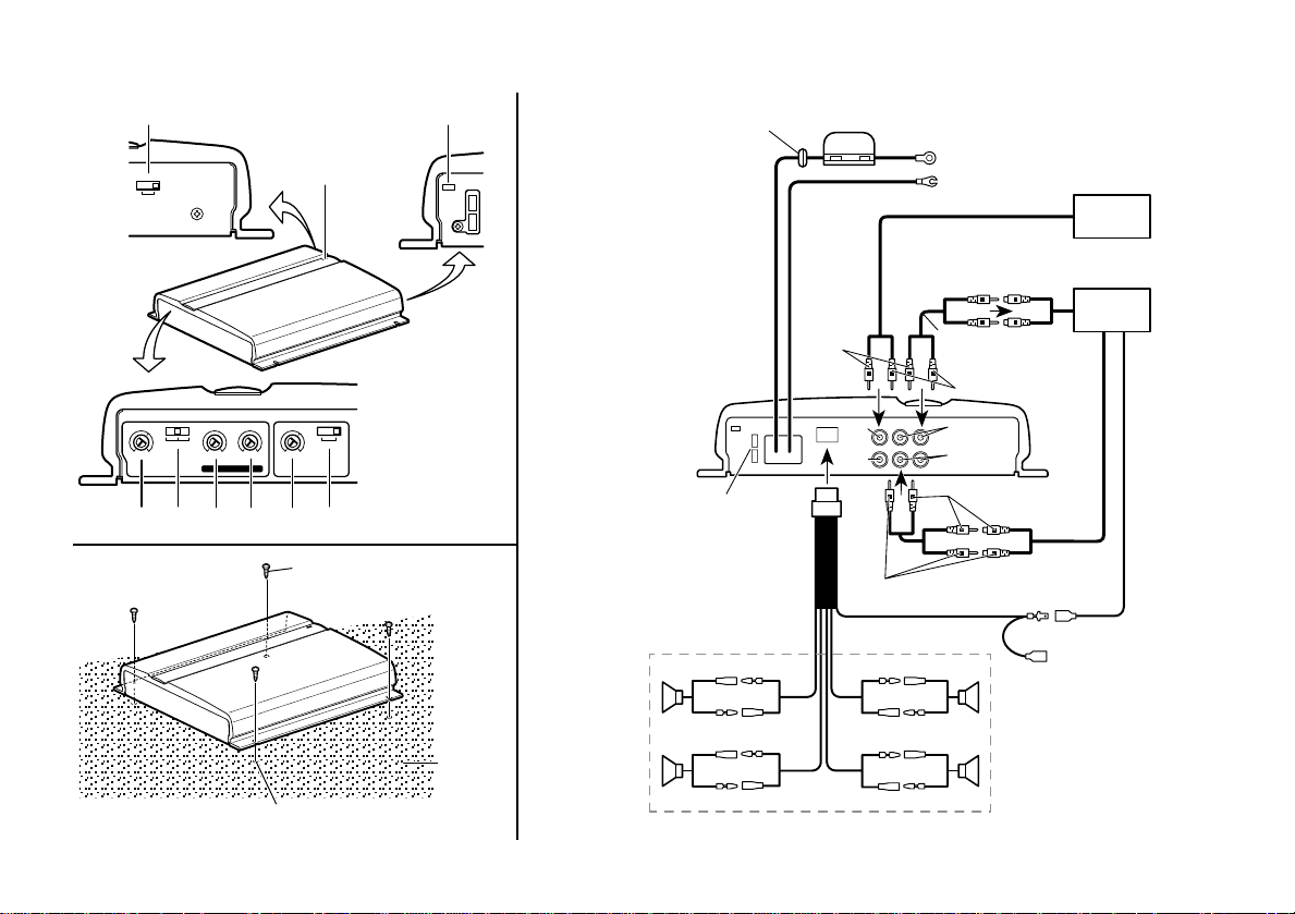
(Fig. 1)
[1] Power Indicator
The power indicator lights when the
power is switched on.
[2] RCA Input Select Switch
For two-channel input, slide this switch
to the left. For four-channel input, slide
this switch to the right.
[3] BFC (Beat Frequency Control) Switch
If you hear a beat while listening to an
AM broadcast with your car stereo,
change the BFC switch using a small
screwdriver.
[4] Input Level Adjustment
Adjusting the input level controls A and
B will help match the output of the car
stereo to the Pioneer amplifier. Input
level control A is used to adjust the
volume of speaker output A; Input level
control B is used to adjust the volume of
speaker ouput B. Normally, set the
switch to the “500 mV” position. If the
output is low even when the volume of
the car stereo is turned up, turn these
controls clockwise. If there is distortion
when the volume of the car stereo is
turned up, turn these controls clockwise.
• If you only use one input pin plug, set
the input level controls for speaker
outputs A and B to the same position.
• Set the input level control to 500mV
when this amplifier is connected to a
Pioneer car stereo with RCA output
jacks. If the sound is too low or distorts, adjust the input level control.
[5] Speaker Out A: LPF (Low-Pass Filter)/
HPF (High-Pass Filter) Select Switch
Set the LPF/HPF select switch as follows
according to the type of the speaker that
is connected to the speaker output
connector and the car stereo system:
LPF/HPF
Select
Switch
LPF
(left)
OFF
(center)
HPF
(right)
* Set the LPF/HPF select switch to the HPF
(right) position if you want to cut the verylow-frequency range because it is not
necessary for the speaker you use.
Audio frequency
range tobe output
Very-low-frequency
range
Very-low-frequency
range to highfrequency range
Low-frequency
range to highfrequency range
*
Speaker Type
Sub-woofer
Other than
sub-woofer
Other than
sub-woofer
[6] Speaker Out A: Bass Boost Level
Control
Bass boost level control can boost the
level around the frequency selected by
the bass boost frequency control to 0 to
12 dB.
[7] Speaker Out A: Bass Boost Frequency
Control
You can select a bass boost frequency
from 40 to 120 Hz with the bass boost
control.
• [6] [7] can be adjusted only when the
LPF/HPF select switch is set to a position
other than HPF .
[8] Speaker Out B: HPF (High-Pass Filter)
Select Switch
Set the HPF select switch as follows
according to the car stereo system and
the type of speaker connected to the
speaker output:
HPF
Select
Switch
OFF
(left)
HPF
(right)
* Set the LPF/HPF select switch to the HPF
(right) position if you want to cut the verylow-frequency range because it is not
necessary for the speaker you use.
Audio frequency
range to be output
Very-low-frequency
range to highfrequency range
Low-frequency
range to highfrequency range
*
Speaker Type
Sub-woofer
Other than
sub-woofer
6
Page 7
Connecting the Unit
CAUTION
• Remove the negative (–) terminal of the
battery to avoid the risk of short-circuit
and damage to the unit.
• Secure the wiring with cable clamps or
adhesive tape. To protect the wiring,
wrap adhesive tape around them where
they lie against metal parts.
• Do not route wires where they will get
hot, for example where the heater will
blow over them. If the insulation heats
up, it may become damaged, resulting in
a short-circuit through the vehicle body.
• Make sure that wires will not interfere
with moving parts of the vehicle, such as
the gearshift, handbrake or seat sliding
mechanism.
• Do not shorten any leads. Otherwise the
protection circuit may fail to work when it
should.
• Never feed power to other equipment by
cutting the insulation of the power supply
wire to tap from the wire. The current
capacity of the wire will be exceeded,
causing overheating.
• Always use the special red battery power
and ground wire [RD-222], which is sold
separately. Connect the special red
battery power cord directly to the car
battery and the black ground wire to the
car body. (The special red battery power
and ground wire [RD-222] are designed
so that the amplifier can be connected
safely.)
To prevent damage
• Do not ground the speaker wire directly
or connect a negative (–) wire for several
speakers.
• Speakers to be connected to the amplifier
should conform with the standards listed
below. Otherwise damage will be caused
to the speaker. The speaker impedance
must be 2 to 8 ohms.
Speaker
Channel Type
Four-
channel
Two-
channel
Threechannel
Speaker
output A
Threechannel
Speaker
output B
Sub-woofer
Other than Max. input:
sub-woofer Min. 60 W
Sub-woofer
Other than Max. input:
sub-woofer Min. 140 W
Sub-woofer
Other than Max. input:
sub-woofer Min. 60 W
Sub-woofer
Other than Max. input:
sub-woofer Min. 140 W
Power
Nominal input:
Min. 30 W
Nominal input:
Min. 70 W
Nominal input:
Min. 30 W
Nominal input:
Min. 70 W
If many units are connected
ENGLISH
• If you let the car engine idle for a long
time with the car stereo on, the battery
may go dead. Turn the car stereo off
when the engine is idling.
• If the blue lead of the amplifier is connected to the power terminal through the
ignition switch (12 VDC), the amplifier will
always be on when the ignition is on—
regardless of whether the car stereo is on
or off. Because of this, the battery could
go dead if you let the engine idle.
• This unit is for vehicles with a 12-volt
battery and negative grounding. Before
installing it in a recreational vehicle, truck,
or bus, check the battery voltage.
• Install and route the separately sold
special red battery wire [RD-222] as
faraway as possible from the speaker
wires. Install and route the separately
sold special red battery wire and ground
wire [RD-222], speaker wires, and the
amplifier as faraway as possible from the
antenna, antenna cable and tuner.
(Fig. 2)
[9] Special red battery wire [RD-222]
(sold separately)
After making all other connections
at the amplifier, connect the battery
lead terminal of the amplifier to the
positive (+) terminal of the battery.
[10] Ground wire (black) [RD-222]
(sold separately)
Connect to metal body or chassis.
[11] Fuse (Special red battery power wire:
30 A, Amplifier: 25 A)
7
Page 8

[12] Grommet
POWER
terminal
Terminal
screw
Special red
battery wire [RD-222]
(sold separately)
GND
terminal
Ground wire
(black) [RD-222]
(sold separately)
Terminal
screw
Fuse
(30 A)
Insert the
O-ring rubber
grommet into
the vehicle body.
Drill an 8-mm
hole into the
vehicle body.
Interior of
the vehicle
Engine
compartment
Special red
battery wire [RD-222]
(sold separately)
After making all
other connections
at the amplifier,
connect the battery
lead terminal of the
amplifier to the
positive (+) terminal
of the battery.
[13] Amplifier with RCA input pin jacks
[14] RCA input
[15] Car stereo with RCA output pin jacks
[16] External Output
For details on how to connect to RCA
input jacks A and B, see the
“Connecting the Speakers and Input
wires” section.
If only input pin plug, do not connect
anything to RCA input jack B.
[17] White
[18] Red
[19] Connecting wires with RCA pin plugs
(sold separately)
[20] RCA input pin jack A, B
[21] RCA output pin jacks
[22] Blue
Connect the male terminal of this wire
to the blue wire of the car stereo
(system control terminal). The female
terminal can be connected to the auto-
antenna relay control terminal.
If the car stereo does not have a
system remote control terminal,
connect the male terminal to the power
terminal through the ignition switch.
[23] Speaker output terminal
See the “Connecting the Speakers and
Input wires” section for speaker con-
nection instructions.
8
Connecting the Power Terminal
• Always use the special red battery power
and ground wire [RD-222], which is sold
separately. Connect the special red
battery power cord directly to the car
battery and the black ground wire to the
car body. (The special red battery power
and ground wire [RD-222] are designed
so that the amplifier can be connected
safely.)
Pass the special red battery wire from the
engine compartment to the interior of the
vehicle.
Fig. 4
Connect the special red battery wire to the
POWER terminal (+), and the black ground
wire to the GND terminal (–).
Fig. 5 Fig. 6
• Securely fasten the special red battery
wire and the ground wires with terminal
screws.
Connecting the Speakers and Input
wires
The speaker output mode can be fourchannel, three-channel (stereo + mono) or
two-channel (stereo, mono). To connect the
speaker wires to suit the mode. Connect the
speakers according to figures on following
pages.
Page 9

2
CH
INPUT SELECT
4
CH
L
R
R
L
R
L
R
L
+
+≠+
≠
≠≠
+
≠≠
+
≠
++
[24]
[25]
[36]
[37]
[28]
[29]
[30]
[17]
[32]
[18]
[21]
[2]
[31]
[30]
[29]
[28]
[35]
[18]
[16]
[16]
[17]
[19]
[33]
[34]
2
CH
INPUT SELECT
4
CH
L
R
+
+≠+
≠
≠≠
+
≠≠
++
≠≠
++
R
L
R
L
R
L
[24]
[25]
[26]
[27]
[28]
[32]
[17]
[29]
[30]
[18]
[21]
[33]
[34]
[2]
[31]
[35]
[30]
[29]
[28]
[18]
[16]
[17]
[16]
[19]
Four-channel mode (Fig. 7)
[2] RCA Input Select Switch
For two-channel input, slide this switch
to the left. For four-channel input, slide
this switch to the right.
[16] Output (Front/Rear)
If only one input pin plug is used, do not
connect anything to RCA input jack B.
[17] White
[18] Red
[19] Connecting wires with RCA pin plugs
(sold separately)
[21] RCA output pin jacks
[24] Speaker out B: Speaker (right)
[25] Speaker out B: Speaker (left)
[26] Speaker out A: Speaker (left)
[27] Speaker out A: Speaker (right)
Fig. 7
[28] Black cover
[29] Black stripe
[30] Green cover
[31] Green stripe
[32] To RCA input pin jacks
[33] RCA input pin jack A
[34] RCA input pin jack B
Fig. 8
• Connect the front or rear output pin plugs
to jacks [33] or [34], according to your
system.
[35] If only one input pin plug is used, do not
connect anything to RCA input jack B.
Three-channel mode (Fig. 8)
[2] RCA Input Select Switch
For two-channel input, slide this switch
to the left. For four-channel input, slide
this switch to the right.
[16] Output (Front/Rear)
If only one input pin plug is used, do not
connect anything to RCA input jack B.
[17] White
[18] Red
[19] Connecting wires with RCA pin plugs
(sold separately)
[24] Speaker out B: Speaker (right)
[25] Speaker out B: Speaker (left)
[28] Black cover
[29] Black stripe
[30] Green cover
[31] Green stripe
[32] To RCA input pin jacks
[33] RCA input pin jack A
[34] RCA input pin jack B
• Connect the front or rear output pin plugs
to jacks [33] or [34], according to your
system.
[35] If only one input pin plug is used, do not
connect anything to RCA input jack B.
[36] No connection
[37] Speaker out A: Speaker (mono)
ENGLISH
9
Page 10

2
CH
INPUT SELECT
4
CH
L
R
R
L
R
L
+
+
≠≠
≠
+
≠≠
+
≠
++
[36]
[40]
[36]
[40]
[30]
[31]
[17][18]
[19]
[16]
[36]
[2]
[29]
[30]
[33]
[17]
[21]
[28]
[32]
[18]
[28]
[29]
2
CH
INPUT SELECT
4
CH
L
R
+
≠
≠
+
+
+
+
≠
≠
≠
+
≠
R
L
R
L
[36]
[38]
[36]
[39]
[30]
[31]
[17][18]
[19]
[16]
[36]
[2]
[30]
[28]
[29]
[33]
[21]
[32]
[17]
[18]
10
Two-channel mode (stereo) (Fig. 9)
[2] RCA Input Select Switch
Slide this switch to the left.
[16] Output
[17] White
[18] Red
[19] Connecting wires with RCA pin plugs
(sold separately)
[21] RCA output pin jacks
[28] Black cover
[29] Black stripe
[30] Green cover
[31] Green stripe
[32] To RCA input pin jacks
[33] RCA input pin jack A
[36] No connection
[38] Speaker (right)
[39] Speaker (left)
Two-channel mode (mono) (Fig. 10)
Fig. 9
[2] RCA Input Select Switch
Slide this switch to the left.
[16] Output
[17] White
[18] Red
[19] Connecting wires with RCA pin plugs
(sold separately)
[21] RCA output pin jacks
[28] Black cover
[29] Black stripe
[30] Green cover
[31] Green stripe
[32] To RCA input pin jacks
[33] RCA input pin jack A
[36] No connection
[40] Speaker (mono)
Fig. 10
Installation
CAUTION
• Do not install in:
— Places where it could injure the driver
or passengers if the vehicle stops
suddenly.
— Places where it may interfere with the
driver, such as on the floor in front of
the driver’s seat.
• Make sure that wires are not caught in the
sliding mechanism of the seats, resulting
in a short-circuit.
• Confirm that no parts are behind the
panel when drilling a hole for installation
of the amplifier. Protect all cables and
important equipment such as fuel lines,
brake lines and the electrical wiring from
damage.
• Install tapping screws in such a way that
the screw tip does not touch any wire.
This is important to prevent wires from
being cut by vibration of the car, which
can result in fire.
• To ensure proper installation, use the
supplied parts in the manner specified. If
any parts other than the supplied ones
are used, they may damage internal parts
of the amplifier, or they may become
loose and the amplifier may shut down.
Page 11

To prevent malfunction
• To ensure proper heat dissipation of the
amplifier, take care of the following
during installation.
— Allow adequate space above the
amplifier for proper ventilation.
— Do not cover the amplifier with a floor
mat or carpet.
• Do not install the amplifier near a door
where it may get wet with rain.
• Do not install the amplifier on unstable
places such as the spare tire board.
• The rigidity for installation differs with the
car model and installation location.
Secure the amplifier at a sufficiently rigid
location.
• Make temporary connections first and
check that the amplifier and the system
operate properly.
• After installing the amplifier, confirm that
the spare tire, jack and tools can be taken
out smoothly.
Example of installation on the floor
mat or on the chassis
1.Place the amplifier where it is to be
installed. Insert the supplied tapping
screws (4 × 18 mm) into the screw holes.
Push on the screws with a screwdriver so
they make marks where the installation
holes are to go.
2.Drill 2.5-mm diameter holes at the point
marked, and install the amplifier, either
on the carpet or directly on the chassis.
(Fig. 3)
[41] Tapping-screws (4 × 18 mm)
[42] Drill a 2.5-mm-diameter hole
[43] Floor mat or chassis
Precautions
In case of trouble
When the unit does not operate
properly, contact your dealer or the
nearest authorized PIONEER Service
Station.
In the United States please call 1-800421-1404 for product information or your
nearest service center or 1-800-228-7221
for information on parts.
ENGLISH
11
Page 12

Specifications
Power source ..................14.4 V DC (10.8 — 15.6 V allowable)
Grounding system ......................................Negative type
Current consumption ..............18 A (at continuous power, 4Ω)
Average current drawn* ...............5.5 A (4Ω for four channels)
10 A (4Ω for two channel)
Fuse ..................................................................25 A
Dimensions ...........................206 (W) × 50 (H) × 270 (D) mm
[8-1/8 (W) × 2 (H) × 10-5/8 (D) in.]
Weight .............2.9 kg (3.3 lbs.) (Leads for wiring not included)
Maximum power output................60 W × 4/140 W × 2 (EIAJ)
Continuous power output
..............30 W × 4 (at 14.4V, 4Ω, 20 — 20,000 Hz, 0.08% THD)
70 W × 2 (at 14.4V, 4Ω, 20 — 20,000 Hz, 0.8% THD)
35 W × 4 (at 14.4V, 2Ω, 20 — 20,000 Hz, 0.8% THD)
20 W × 4 (at 12V, 4Ω, 20 — 20,000 Hz, 0.08% THD)
50 W × 2 (at 12V, 4Ω, 20 — 20,000 Hz, 0.8% THD)
25 W × 4 (at 12V, 2Ω, 20 — 20,000 Hz, 0.8% THD)
Load impedance...............................4Ω (2 — 8Ω allowable)
Frequency response .................10 — 50,000 Hz (+0 dB, –1 dB)
Signal-to-noise ratio .......................108 dB (IHF – A network)
Separation.................................................65 dB (1 kHz)
Low pass filter ...............................Cut off frequency: 80Hz
Cut off slope: –18 dB/oct
High pass filter ..............................Cut off frequency: 80 Hz
Cut off slope: –12 dB/oct
Bass boost .................................Frequency: 4 0 — 120 Hz
Gain: 0 — 12 dB
Input level / impedance...............................0.4 — 2 V/22 kΩ
These specifications were determined and are presented in
accordance with specification standards established by the Ad
Hoc Committee of Car Stereo Manufacturers.
Note:
Specifications and the design are subject to possible modification
without notice due to improvements.
*Average current drawn
The average current drawn is nearly the maximum current drawn
by this unit when an audio signal is input. Use this value when
working out total current drawn by multiple power amplifiers.
12
Page 13

Cher Client :
La sélection d’un équipement audio de qualité comme l’unité
que vous venez d’acheter n’est que le début de votre plaisir musical.
Maintenant, il est temps de penser à la manière de profiter au
maximum des plaisirs que vous offre votre équipement. Ce fabricant
et le Groupe “Consumer Electronics Group” de l’Association des
Industries Electroniques veut que vous profitiez au maximum de
votre équipement en l’utilisation à un niveau sûr. Un niveau qui
permet au son d’être fort et clair, sans beuglement ennuyant ou
distorsion — et, ce qui est plus important, sans affecter votre ouïe
sensible.
Le son peut être décevant. Avec le temps, le “niveau de confort”
de votre ouïe s’adapte aux volumes sonores plus élevés. Ainsi, les
sons “normaux” peuvent en fait être forts et affecter votre ouïe.
Protégez-vous contre cela en réglant votre équipement à un niveau
sûr AVANT l’adaptation de votre ouïe.
Pour établir un niveau sûr :
• Démarrer votre commande de volume à un réglage bas.
• Augmentez lentement le son jusqu’à ce que vous l’entendiez
confortablement et clairement, sans distorsion.
Lorsque vous avez établi un niveau sonore confortable :
• Réglez le cadran et laissez-le tel quel.
En prenant une minute pour faire cela, vous pourrez éviter des
dommages ou des pertes de sensibilités d’écoute dans le futur.
Après tout, nous voulons que vous écoutiez pendant toute votre vie.
Nous voulons que vous écoutiez pendant toute
votre vie
Utilisé avec sagesse, votre nouvel équipement sonore sera une source de
plaisir pendant toute votre vie. Comme les dommages de l’ouïe provenant
d’un bruit fort ne sont souvent détectables que lorsqu’il est trop tard, ce
fabricant et le Groupe “Consumer Electronics Group” de l’Association des
Industries Electroniques vous recommandent d’éviter toute exposition
prolongée à un bruit excessif. Cette liste de niveaux sonores est incluse
pour votre protection.
Niveau de
Décibels Exemple
30 Bibliothèque tranquille, chuchotement
40 Salon, réfrigérateur, chambre à distance de la circulation
50 Circulation légère, conversation normale, bureau tranquille
60 Climatiseur à 20 pieds, machine à coudre
70 Aspirateur, sèche-cheveux, restaurant bruyant
80 Circulation moyenne en ville, évacuateurs de déchets, réveils à
LES BRUITS SUIVANTS PEUVENT ETRE DANGEREUX
DANS LE CAS D’UNE EXPOSITION CONSTANTE
90 Métro, motocyclette, circulation de camion, tondeuse à gazon
100 Collecteurs de poubelle, scie à chaîne, perceuse pneumatique
120 Concert de groupe rock devant les haut-parleurs, coup de
140 Coup de pistolet, avion à réaction
180 Aire de lancement d’une fusée
Ces informations ont été gracieusement fournies par la Fondation de la Recherche
pour les Sourds.
deux pieds.
tonnerre
ENGLISH
FRANÇAIS
13
Page 14

Symboles
Les deux symboles suivants sont utilisés
dans ce manuel.
PRECAUTION
— Ne jamais exécuter cette
opération.
Ce symbole indique des actions dangereuses qui doivent être évitée à tout
prix.
Note
— Suivre les instructions
soigneusement.
Ce symbole indique une action qui
peut causer un défaut de l’équipement
au cas où elle est exécutée de manière
erronée.
AVERTISSEMENT
• Pour une bonne sécurité de la conduite et
pour une conduite appropriée de la
voiture, maintenir le volume à un bas
niveau de telle manière que l’on puisse
encore entendre le son normal du trafic.
• Vérifier les connexions de l’alimentation
et des haut-parleurs, si le fusible du fil de
la batterie rouge spécial [RD-222] ou de
l’amplificateur est grillé. Détecter la cause
du problème et l’éliminer, puis remplacer
le fusible avec un autre fusible de même
dimension et valeur nominale.
• Pour éviter un mauvais fonctionnement à
l’amplificateur et aux haut-parleurs, le
circuit de protection interrompra l’alimentation à l’amplificateur (le son s’interrompra dans ce cas) lorsqu’une condition
anormale se produit. Dans tel un cas,
commuter l’alimentation du système à la
position “OFF” (arrêt), puis vérifier la
connexion de l’alimentation et des hautparleurs. Détecter la cause et résoudre le
problème.
• Consulter le fournisseur si on ne peut pas
détecter la cause du problème.
• Pour éviter toute secousse électrique ou
court-circuit durant la connexion et
l’installation, s’assurer de débrancher la
borne négative (–) de la batterie d’avance.
• Toujours utiliser les câbles de la batterie
rouge spécial et les câbles de masse [RD222], qui est vendu séparément.
Connecter les câbles de la batterie rouge
spécial directement à la batterie de la
voiture et les câbles de masse à la carrosserie de la voiture. (Les câbles de la
batterie rouge spécial et les câbles de
masse [RD-222] est conçu de telle
manière que l’amplificateur puisse être
connecté sûrement).
• Confirmer qu’aucune pièce n’est mise en
position derrière le panneau lorsque l’on
perce un trou pour l’installation de
l’amplificateur. Protéger tous les câbles et
pièces importantes telles que durites de
carburant, conduites de frein et faisceau
de câblage de l’alimentation contre un
endommagement.
• Pour assurer une dissipation de chaleur
appropriée de l’amplificateur, prendre
soin des points suivants durant l’installation.
— Laisser un espace approprié sur la
partie supérieure de l’amplificateur et
sur sa partie supérieure pour obtenir
une ventilation appropriée.
— Ne pas recouvrir l’amplificateur avec
un tapis ou une moquette.
14
Page 15

Réglage de cette unité
(Fig. 1)
[1] Indicateur d’alimentation
Cet indicateur s’allume quand l’alimentation est en fonction.
[2] Sélecteur d’entrée RCA
Pour l’entrée à deux canaux, déplacer ce
sélecteur à gauche. Pour l’entrée à quatre
canaux, déplacer ce sélecteur à droite.
[3] Interrupteur BFC (Commande de
fréquence de battement)
Si l’on entend un battement pendant
que l’on écoute une transmission AM
avec le stéréo de la voiture, changer
l’interrupteur BFC en utilisant un petit
tournevis.
[4] Réglage du niveau d’entrée
Le réglage des commandes A et B de
niveau d’entrée permettra d’apparier la
sortie du stéréo de voiture à l’amplificateur Pioneer. La commande A du niveau
d’entrée s’utilise pour régler le volume de
la sortie A de haut-parleur, tandis que la
commande B du niveau d’entrée s’utilise
pour régler le volume de la sortie B de
haut-parleur. Régler normalement le
commutateur sur la position “500 mV”.
Si la sortie est basse même lorsque le
volume du stéréo de la voiture est augmenté, tourner ces commandes dans le
sens des aiguilles d’une montre. S’il y a
une distorsion lorsque le volume du
stéréo de voiture est augmenté, tourner
ces commandes dans le sens contraire
des aiguilles d’une montre.
• Si l’on utilise seulement une fiche à
broches d’entrée, régler la commande
du niveau d’entrée pour les sorties A et
B du haut-parleur à la même position.
• Régler la commande de niveau
d’entrée à la valeur de 500 mV lorsque
cet amplificateur est connecté à un
stéréo pour voiture Pioneer avec des
Prises jack à broches de sortie RCA. Si
le son est trop bas ou est déformé,
régler la commande du niveau
d’entrée.
[5] Sortie de haut-parleur A: Sélecteur LPF
(Filtre passe-bas)/HPF (Filtre passe-haut)
Régler le sélecteur LPF/HPF de la
manière suivante, selon le type de hautparleur connecté au connecteur de sortie
du haut-parleur et au système stéréo de
la voiture:
Sélec-
LPF/HPF
(gauche)
(centre)
(droite)
* Régler le sélecteur LPF/HPF sur la position
Plage de fréquence
teur
OFF
HPF
audio devant être
émise
LPF
Plage de très basse
fréquence
Plage de très basse
fréquence à plage
de haute fréquence
Plage de basse
fréquence à plage
de haute fréquence
*
HPF (droite) si l’on désire couper la gamme
des fréquences très basses, car elle n’est
pas nécessaire pour le haut-parleur en
usage.
Type
haut-
parleur
Sub-woofer
Autre que
sub-woofer
Autre que
sub-woofer
[6] Sortie de haut-parleur A: Commande du
niveau de boost des basses
La commande du niveau de boost des
basses peut renforcer le niveau autour
de la fréquence sélectionée par la
commande de fréquence de boost des
basses sur une valeur de 0 à 12 dB.
[7] Sortie de haut-parleur A: Commande de
fréquence de boost des basses
On peut sélectionner une fréquence de
boost des basses de 40 à 120 Hz avec la
commande de boost des basses.
• [6] [7] Peut être réglé seulement lorsque
le sélecteur LPF/HPF est réglé à la position autre que celle HPF.
[8] Sortie de haut-parleur B : Sélecteur HPF
(Filtre passe-haut)
Régler le sélecteur HPF de la manière
suivante, selon le système stéréo de la
voiture et le type de haut-parleur connecté à la sortie du haut-parleur:
Sélec-
(gauche)
(droite)
* Régler le sélecteur LPF/HPF sur la position
Plage de fréquence
teur
HPF
OFF
HPF
audio devant être
émise
Plage de très basse
fréquence à plage
de haute fréquence
Plage de basse
fréquence à plage
de haute fréquence
*
HPF (droite) si l’on désire couper la gamme
des fréquences très basses, car elle n’est
pas nécessaire pour le haut-parleur en
usage.
Type
haut-parleur
Sub-woofer
Autre que
sub-woofer
ENGLISH
FRANÇAIS
15
Page 16

Comment connecter les
unités
PRECAUTION
• Enlever la borne négative (–) de la batterie pour éviter tous risque de courtcircuit et pour éviter un endommagement
à l’unité.
• Fixer le câblage au moyen des attaches
de câble ou une bande adhésive. Pour
protéger le câblage, enrouler la bande
adhésive autour des câbles à l’endroit où
ceux-ci sont placés en contact contre les
pièces métalliques.
• Ne pas acheminer les câbles aux
emplacements pouvant se réchauffer, par
exemple là où le dispositif de chauffage
les chauffera. Si l’isolement se réchauffe,
il pourrait s’endommager, ceci pouvant
résulter en un court-circuit à la carrosserie
du véhicule.
• S’assurer que les câbles ne soient pas en
contact avec des pièces mobiles du
véhicule, tel que levier de changement de
vitesses, frein à main ou mécanisme à
coulisse du siège.
• Ne pas court-circuiter les câbles. Sinon,
le circuit de protection risque de ne pas
fonctionner.
• Ne jamais alimenter un autre appareil en
coupant l’isolation du fil d’alimentation
pour brancher dans le fil. L’intensité de
courant du fil sera dépassée provoquant
ainsi une surchauffe.
• Toujours utiliser les câbles de la batterie
rouge spécial et les câbles de masse [RD222], qui est vendu séparément.
Connecter les câbles de la batterie rouge
spécial directement à la batterie de la
voiture et les câbles de masse à la carrosserie de la voiture. (Les câbles de la
batterie rouge spécial et les câbles de
masse [RD-222] est conçu de telle
manière que l’amplificateur puisse être
connecté sûrement).
Pour éviter tout endommagement
• Ne pas mettre à la masse le fil du hautparleur directement ou connecter un fil
négatif (–) pour plusieurs haut-parleurs.
• Les haut-parleurs devant être connectés à
l’amplificateur devraient se conformer
aux normes comme indiqué ci-après.
Dans le cas contraire, un endommagement sera causé au haut-parleur.
L’impédance de haut-parleur doit être de
2 à 8 ohms.
Haut-parleur
Canal Type
Quatre
canaux
Deux
canaux
Trois
canaux
Sortie haut-
parleur A
Trois
canaux
Sortie haut-
parleur B
Sub-woofer
Autre que Entrée maximum:
sub-woofer Min. 60 W
Sub-woofer
Autre que Entrée maximum:
sub-woofer Min. 140 W
Sub-woofer
Autre que Entrée maximum:
sub-woofer Min. 60 W
Sub-woofer
Autre que Entrée maximum:
sub-woofer Min. 140 W
Alimentation
Entrée nominale:
Min. 30 W
Entrée nominale:
Min. 70 W
Entrée nominale:
Min. 30 W
Entrée nominale:
Min. 70 W
16
Page 17

Au cas où un grand nombre
d’unités sont connectées
• Si on laisse le moteur de la voiture
marcher au ralenti pendant une longue
période de temps avec le stéréo de la
voiture activé, la batterie pourrait s’épuiser. Désactiver le stéréo de la voiture
lorsque le moteur marche au ralenti.
• Si le fil bleu de l’amplificateur est connecté à la borne d’alimentation à travers le
commutateur de l’allumage (12 V, C.C.),
l’amplificateur sera toujours activé
lorsque l’allumage est activé, indépendamment du fait que le stéréo de la
voiture est activé ou désactivé. A cause
de cette condition, la batterie pourrait
s’épuiser si l’on laisse le moteur marcher
au ralenti.
• Cet appareil est destiné aux véhicules
avec une batterie de 12 V, à masse
négative. Avant de l’installer dans un
véhicule de loisir, un camion ou un car,
vérifier la tension de la batterie.
• Installer et acheminer le fil de la batterie
rouge spécial vendu séparément [RD-222]
aussi loin que possible des fils de hautparleur. Installer et acheminer le fil de la
batterie rouge spécial vendu séparément
et le fil de masse [RD-222], les fils de
haut-parleur, et l’amplificateur aussi loin
que possible de l’antenne, du câble de
l’antenne et du syntonisateur.
(Fig. 2)
[9] Fil de la batterie rouge special [RD-222]
(vendu séparément)
Après que toutes les autres connexions
aient été faites à l’amplificateur, connecter la borne du fil de la batterie de
l’amplificateur à la borne positive (+)
de la batterie.
[10] Fil de masse (noir) [RD-222]
(vendu séparément)
Connecter à la carrosserie métallique
ou au châssis.
[11] Fusible (Fil de la batterie rouge special:
30A, Amplificateur: 25A )
[12] Canon isolant
[13] Amplificateur avec jacks à broches
d’entrée RCA
[14] Entrée RCA
[15] Stéréo de la voiture avec prises jack de
goupille de sortie RCA
[16] Sortie externe
Pour les détails sur la méthode de
connexion aux prises jack d’entrée
RCA A et B, voir la section “Comment
connecter les haut-parleurs et les fils
d’entrée”.
Si l’on utilise seulement une fiche à
broches d’entrée, ne rien connecter au
prise jack d’entrée B de RCA.
[17] Blanc
[18] Rouge
[19] En connectant les fils avec les fiches de
goupille RCA (vendu séparément)
[20] Prise jack à broches d’entrée A, B RCA
[21] Prises jack à broches de sortie RCA
[22] Bleu
Connecter la borne mâle de ce fil au fil
bleu stéréo pour voiture (borne de
commande du système). La borne
femelle peut être connectée à la borne
de commande du relais d’antenna
automatique.
Si le stéréo de la voiture ne présente
pas de borne de télécommande du
système, connecter la borne mâle à la
borne d’alimentation à travers le
commutateur d’allumage.
[23] Borne de sortie du haut-parleur.
Voir la section “Comment connecter le
haut-parleurs et les fils d’entrée” pour
les instructions sur la connexion du
haut-parleur.
ENGLISH
FRANÇAIS
17
Page 18

Comment connecter la borne
2
CH
INPUT SELECT
4
CH
L
R
R
L
R
L
R
L
+
+≠+
≠
≠≠
+
≠≠
+
≠
++
[24]
[25]
[36]
[37]
[28]
[29]
[30]
[17]
[32]
[18]
[21]
[2]
[31]
[30]
[29]
[28]
[35]
[18]
[16]
[16]
[17]
[19]
[33]
[34]
2
CH
INPUT SELECT
4
CH
L
R
+
+≠+
≠
≠≠
+
≠≠
++
≠≠
++
R
L
R
L
R
L
[24]
[25]
[26]
[27]
[28]
[32]
[17]
[29]
[30]
[18]
[21]
[33]
[34]
[2]
[31]
[35]
[30]
[29]
[28]
[18]
[16]
[17]
[16]
[19]
Fil de la batteriè
rouge spécial [RD-222]
(vendu séparément)
Borne POWER
(alimentation)
Vis de
la borne
Borne GND
(masse)
Fil de la masse
[RD-222] (vendu
séparément)
Vis de
la borne
Fusible
(30 A)
Insérer le
canon isolant
en caoutchouc
du joint torique
dans le corps
du véhicule.
Percer un
trou de
8-mm à
travers la
carrosserie
du véhicule.
Intérieur du
véhicule
Compartiment du
moteur
Fil de la batterie
rouge spécial [RD-222]
(vendu séparément)
Après avoir effectué
toutes les autres
connexions à
l’amplificateur,
connecter la borne
du fil de la batterie
de l’amplificateur à
la borne positive (+)
de la batterie.
d’alimentation
• Toujours utiliser les câbles de la batterie
rouge spécial et les câbles de masse [RD222], qui est vendu séparément.
Connecter les câbles de la batterie rouge
spécial directement à la batterie de la
voiture et les câbles de masse à la carrosserie de la voiture. (Les câbles de la
batterie rouge spécial et les câbles de
masse [RD-222] est conçu de telle
manière que l’amplificateur puisse être
connecté sûrement).
Passer le fil de la batterie rouge spécial à
partir du compartiment du moteur à l’intérieur du véhicule.
Connecter le fil de la batterie rouge spécial
à la borne POWER (alimentation) (+), et le
fil de masse, à la borne GND (masse) (–).
18
Fig. 5 Fig. 6
Fig. 7
• Serrer sûrement le fil de la batterie rouge
spécial et les fils de la masse avec les vis
de borne.
Comment connecter les hautparleurs et les fils d’entrée
Le mode de sortie du haut-parleur peut être
de quatre canaux, trois canaux (stéréo +
mono) ou, deux canaux (stéréo, mono).
Pour connecter les fils du haut-parleur afin
de correspondre au mode. Connecter les
haut-parleurs selon la figure ci-après.
Fig. 4
Fig. 8
Page 19

2
CH
INPUT SELECT
4
CH
L
R
R
L
R
L
+
+
≠≠
≠
+
≠≠
+
≠
++
[36]
[40]
[36]
[40]
[30]
[31]
[17][18]
[19]
[16]
[36]
[2]
[29]
[30]
[33]
[17]
[21]
[28]
[32]
[18]
[28]
[29]
2
CH
INPUT SELECT
4
CH
L
R
+
≠
≠
+
+
+
+
≠
≠
≠
+
≠
R
L
R
L
[36]
[38]
[36]
[39]
[30]
[31]
[17][18]
[19]
[16]
[36]
[2]
[30]
[28]
[29]
[33]
[21]
[32]
[17]
[18]
Mode à quatre canaux (Fig. 7)
[2] Sélecteur d’entrée RCA
Pour l’entrée à deux canaux, déplacer
ce sélecteur à gauche. Pour l’entrée à
quatre canaux, déplacer ce sélecteur à
droite.
[16] Sortie (avant/arrière)
Si l’on utilise seulement une fiche à
broches d’entrée, ne rien connecter au
Prise jack d’entrée B de RCA.
[17] Blanc
[18] Rouge
[19] En connectant les fils avec les fiches de
goupille RCA (vendu séparément)
[21] Prises jack à broches de sortie RCA
[24] Sortie haut-parleur B: haut-parleur
(droite)
[25] Sortie haut-parleur B: haut-parleur
(gauche)
[26] Sortie haut-parleur A: haut-parleur
(gauche)
[27] Sortie haut-parleur A: haut-parleur
(droite)
[28] Couvercle noir
[29] Bande noire
[30] Couvercle vert
[31] Bande verte
[32] A jacks à broches d’entrée
[33] Prises jack à broches d’entrée A
[34] Prises jack à broches d’entrée B
• Connecter les fiches à broches de sortie
avant ou arrière aux prises jack [33] ou
[34], selon le type de système.
[35] Si l’on utilise seulement une fiche à
broches d’entrée, ne rien connecter au
jack d’entrée B de RCA.
Mode à trois canaux (Fig. 8)
[2] Sélecteur d’entrée RCA
Pour l’entrée à deux canaux, déplacer
ce sélecteur à gauche. Pour l’entrée à
quatre canaux, déplacer ce sélecteur à
droite.
[16] Sortie (avant/arrière)
Si l’on utilise seulement une fiche à
broches d’entrée, ne rien connecter au
prise jack d’entrée B de RCA.
[17] Blanc
[18] Rouge
[19] En connectant les fils avec les fiches de
goupille RCA (vendu séparément)
[24] Sortie haut-parleur B: haut-parleur
(droite)
[25] Sortie haut-parleur B: haut-parleur
(gauche)
[28] Couvercle noir
[29] Bande noire
[30] Couvercle vert
[31] Bande verte
[32] A jacks à broches d’entrée
[33] Prises jack à broches d’entrée A
[34] Prises jack à broches d’entrée B
• Connecter les fiches à broches de sortie
avant ou arrière aux prises jack [33] ou
[34], selon le type de système.
[35] Si l’on utilise seulement une fiche à
broches d’entrée, ne rien connecter au
prise jack d’entrée B de RCA.
[36] Aucune connexion
[37] Sortie haut-parleur A: haut-parleur
(mono)
ENGLISH
FRANÇAIS
Fig. 9
Fig. 10
19
Page 20

Mode à deux canaux (stéréo) (Fig. 9)
[2] Sélecteur d’entrée RCA
Déplacer ce sélecteur à gauche.
[16] Sortie
[17] Blanc
[18] Rouge
[19] En connectant les fils avec les fiches de
goupille RCA (vendu séparément)
[21] Prises jack à broches de sortie RCA
[28] Couvercle noir
[29] Bande noire
[30] Couvercle vert
[31] Bande verte
[32] A jacks à broches d’entrée
[33] Prises jack à broches d’entrée A
[36] Aucune connexion
[38] Haut-parleur (droite)
[39] Haut-parleur (gauche)
Mode à deux canaux (mono) (Fig. 10)
[2] Sélecteur d’entrée RCA
Déplacer ce sélecteur à gauche.
[16] Sortie
[17] Blanc
[18] Rouge
[19] En connectant les fils avec les fiches de
goupille RCA (vendu séparément)
[21] Prises jack à broches de sortie RCA
[28] Couvercle noir
[29] Bande noire
[30] Couvercle vert
[31] Bande verte
[32] A jacks à broches d’entrée
[33] Prises jack à broches d’entrée A
[36] Aucune connexion
[40] Haut-parleur (mono)
Installation
PRECAUTION
• Ne pas installer dans des:
— Emplacements où il pourrait blesser le
conducteur ou les passagers si le
véhicule s’arrête brusquement.
— Emplacements où il pourrait déranger
le conducteur, tel que plancher vers
l’avant du siège du conducteur.
• S’assurer que les câbles ne puissent pas
être enchevêtrés dans le mécanisme à
coulisse du siège, ceci pouvant résulter
en un court-circuit.
• Confirmer qu’aucune pièce n’est mise en
position derrière le panneau lorsque l’on
perce un trou pour l’installation de
l’amplificateur. Veiller à bien protéger
tous les câbles et pièces importantes
telles que durites de carburant, conduites
de frein et faisceau de câblage de l’alimentation contre un endommagement.
• Installer les vis auto-serrantes de telle
manière que le bout des vis ne touche
pas aux fils. Cette précaution est importante pour éviter que les câbles ne soient
coupés par les vibrations de la voiture,
ceci pouvant résulter en un incendie.
• Pour assurer une installation appropriée,
utiliser les pièces fournies selon la
manière spécifiée. Si une pièce quelconque autre que celles fournies est utilisée, elle pourrait endommager les pièces
internes de l’unité, ou elle pourrait rester
desserrée et l’unité pourrait se détacher.
Pour éviter un mauvais fonctionnement
• Pour assurer une dissipation de chaleur
appropriée de l’amplificateur, observer
les points suivants durant l’installation.
— Laisser un espace approprié sur la
partie supérieure de l’amplificateur et
sur sa partie supérieure pour obtenir
une ventilation appropriée.
— Ne pas recouvrir l’amplificateur avec
un tapis ou une moquette.
• Ne pas installer l’amplificateur près d’une
porte où il pourrait être exposé à la pluie.
• Ne pas installer l’amplificateur sur des
endroits instables tels que planche de
pneu de rechange.
• La rigidité pour l’installation varie selon le
modèle de voiture et l’emplacement
d’installation.
Fixer l’amplificateur sur un emplacement
suffisamment rigide.
• Effectuer tout d’abord les connexions et
vérifier si l’amplificateur et le système
fonctionnent de manière appropriée.
• Après avoir installé l’amplificateur, confirmer que le pneu de rechange, le cric et
les outils peuvent être retirés facilement.
20
Page 21

Exemple de montage sur l’essuiepieds ou le châssis
1.Placer l’amplificateur là où il doit être
installé. Insérer les vis à taraudage
fournies (4 × 18 mm) dans les trous de vis.
Pousser les vis avec un tournevis, pour
qu’ils fassent des marques, là où les trous
d’installation doivent être positionnés.
2.Perforer des trous de 2,5 mm de diamètre
au point marqué, et installer l’amplificateur, soit sur la moquette, soit directement sur le châssis.
(Fig. 3)
[41] Vis à taraudage fournies (4 × 18 mm)
[42] Percer des trous de 2,5 mm
[43] Tapis de sol ou châssis
Précautions
En cas de problème
Lorsque l’unité ne fonctionne pas correctement, contactez votre revendeur ou
la Station de Service PIONEER la plus
proche.
Aux Etats-Unis, prière de contacter le
No. de téléphone 1-800-421-1404 pour
obtenir des informations sur le produit,
ou bien le centre du service le plus
proche ou le numéro 1-800-228-7221
pour les informations sur les pièces.
Spécifications
Alimentation .................................................CC 14,4 V (10,8 — 15,6 V admissible)
Mise à la masse...........................................................................Type négatif
Consommation courante ......................................18 A (à l a puissance continue, 4Ω)
Consommation électrique moyenne* ............................5,5 A (4Ω pour quatre canaux)
10 A (4Ω pour deux canaux)
Fusible...............................................................................................25 A
Dimensions ............................................................206 (L) × 50 (H) × 270 (P) mm
Poids ...................................................................2,9 kg (cordons non compris)
Puissance de sortie maximum.........................................60 W × 4/140 W × 2 (EIAJ)
Puissance de sortie continue.............30 W × 4 (à 14,4 V, 4 Ω, 20 — 20.000 Hz, 0,08% THD)
70 W × 2 (à 14,4 V, 4 Ω, 20 — 20.000 Hz, 0,8% THD)
35 W × 4 (à 14,4 V, 2 Ω, 20 — 20.000 Hz, 0,8% THD)
20 W × 4 (à 12 V, 4 Ω, 20 — 20.000 Hz, 0,08% THD)
50 W × 2 (à 12 V, 4 Ω, 20 — 20.000 Hz, 0,8% THD)
25 W × 4 (à 12 V, 2 Ω, 20 — 20.000 Hz, 0,8% THD)
Impédance de charge .....................................................4 Ω (2 — 8 Ω admissible)
Réponse en fréquence ..............................................1 0 — 50.000 Hz (+0 dB, –1 dB)
Rapport signal-bruit.........................................................108 dB (réseau IHF – A)
Diaphonie.................................................................................65 dB (1 kHz)
Filtre de passe-bas ....................................................Fréquence de coupure: 80Hz
Pente de coupure: –18 dB/oct
Filtre de passe-haut ..................................................Fréquence de coupure: 80 Hz
Pente de coupure: –12 dB/oct
Boost des basses ........................................................Fréquence: 40 — 120 Hz
Gain: 0 — 12 dB
Niveau de entrée / impédance ......................................................0,4 — 2 V/22 kΩ
Remarque:
Suite aux améliorations apportées à ces équipements, leurs caractéristiques et leur conception sont sujettes à modification sans préàvis.
*Consommation électrique moyenne
La consommation électrique moyenne est presque la consommation maximum de cette
unité, quand un signal audio est introduit. Utiliser cette valeur en cas de consommation
totale par des amplificateurs de puissance multiples.
ENGLISH
FRANÇAIS
21
Page 22

4-1, Meguro 1 chome, Meguro-ku, TOKYO, 153, JAPAN
PIONEER ELECTRONICS (USA) INC.
P.O. Box 1760, Long Beach, California 90801, U.S.A.
TEL: (800) 421-1404
PIONEER ELECTRONIC (EUROPE) N.V.
Haven 1087 Keetberglaan 1, 9120 Melsele, Belgium
TEL: 03/750.05.11
PIONEER ELECTRONICS AUSTRALIA PTY. LTD.
178-184 Boundary Road, Braeside, Victoria 3195, Australia
TEL: (03) 580-9911
PIONEER ELECTRONICS OF CANADA, INC.
300 Allstate Parkway Markham, Ontario L3R 0P2, Canada
TEL: (416) 479-4411
PIONEER ELECTRONICS DE MEXICO S.A. DE C.V.
Augusto Rodin No. 128 PB COL.
San Juan Mixcoac Mexico D.F. CP. 03730
TEL: 52-5-598-3950
<94J01A0K01>
Published by Pioneer Electronic Corporation.
Copyright 1994 by Pioneer Electronic Corporation.
All rights reserved.
Publication de Pioneer Electronic Corporation.
© 1994 Pioneer Electronic Corporation.
Tous droits de reproduction et de traduction reservés.
Printed in U.S.A.
Imprimé au U.S.A.
<HRD0002-A> XH/UC
 Loading...