

Pioneer GMX-374 Service manual
PIONEER CORPORATION 4-1, Meguro 1-Chome, Meguro-ku, Tokyo 153-8654, Japan
PIONEER ELECTRONICS (USA) INC. P.O.Box 1760, Long Beach, CA 90801-1760 U.S.A.
PIONEER EUROPE NV Haven 1087 Keetberglaan 1, 9120 Melsele, Belgium
PIONEER ELECTRONICS ASIACENTRE PTE.LTD. 253 Alexandra Road, #04-01, Singapore 159936
C PIONEER CORPORATION 2002
K-ZZY. NOV. 2002 Printed in Japan
BRIDGEABLE FOUR-CHANNEL POWER AMPLIFIER
GM-X374XR/UC,XR/EW,XR/ES
For details, refer to "Important symbols for good services".
ORDER NO.
CRT3007
BRIDGEABLE
4-CH POWER AMPLIFIER
FUSE 25A
25
GM-X374/XR/UC
2
1
234
12
34
F
E
D
C
B
A
GM-X374/XR/UC
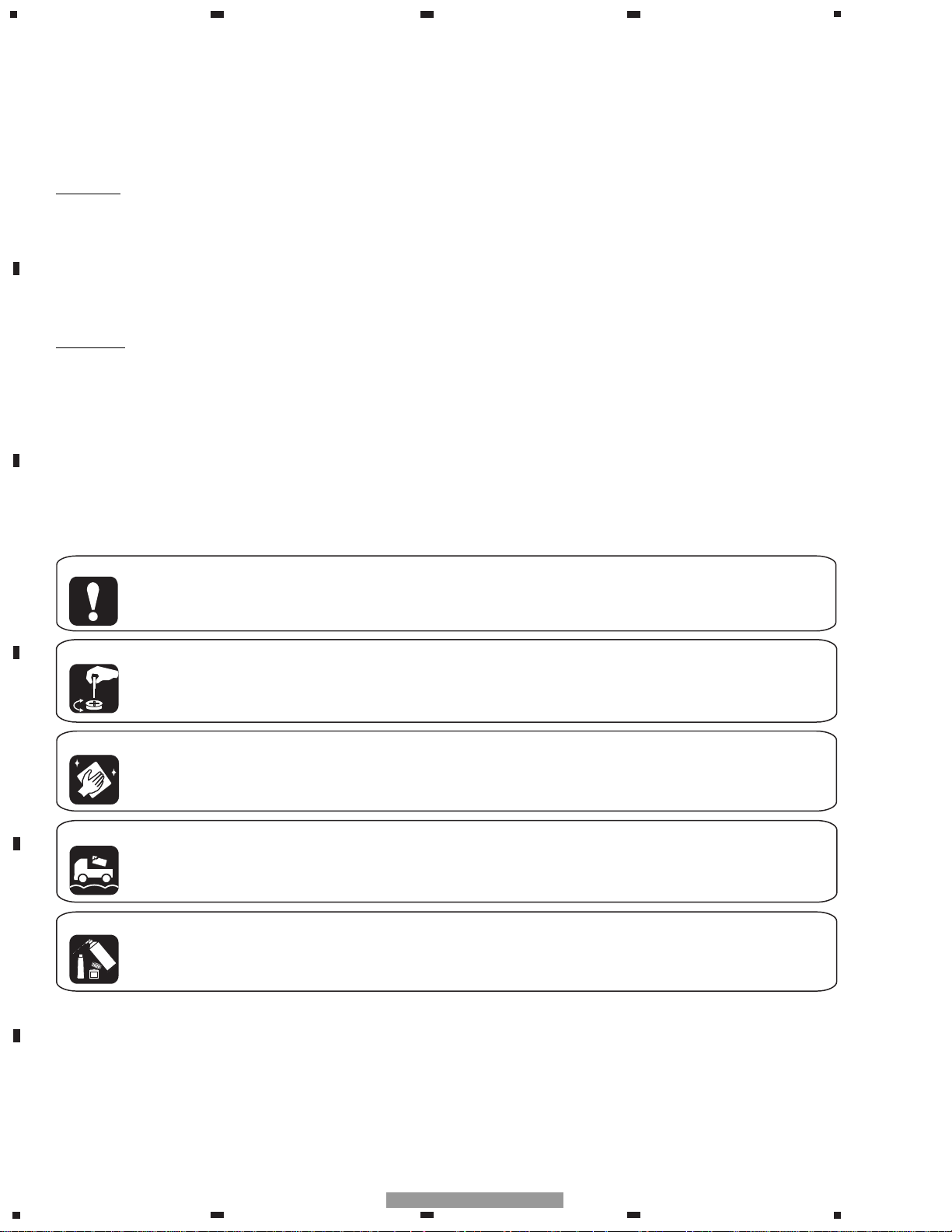
[ Important symbols for good services ]
In this manual, the symbols shown-below indicate that adjustments, settings or cleaning should be made securely.
When you find the procedures bearing any of the symbols, be sure to fulfill them:
2. Adjustments
To keep the original performances of the product, optimum adjustments or specification confirmation is indispensable.
In accordance with the procedures or instructions described in this manual, adjustments should be performed.
3. Cleaning
For optical pickups, tape-deck heads, lenses and mirrors used in projection monitors, and other parts requiring cleaning,
proper cleaning should be performed to restore their performances.
5. Lubricants, glues, and replacement parts
Appropriately applying grease or glue can maintain the product performances. But improper lubrication or applying
glue may lead to failures or troubles in the product. By following the instructions in this manual, be sure to apply the
prescribed grease or glue to proper portions by the appropriate amount.For replacement parts or tools, the prescribed
ones should be used.
4. Shipping mode and shipping screws
To protect the product from damages or failures that may be caused during transit, the shipping mode should be set or
the shipping screws should be installed before shipping out in accordance with this manual, if necessary.
1. Product safety
You should conform to the regulations governing the product (safety, radio and noise, and other regulations), and
should keep the safety during servicing by following the safety instructions described in this manual.
CAUTION
This service manual is intended for qualified service technicians; it is not meant for the casual do-it-yourselfer.
Qualified technicians have the necessary test equipment and tools, and have been trained to properly and safely repair
complex products such as those covered by this manual.
Improperly performed repairs can adversely affect the safety and reliability of the product and may void the warranty.
If you are not qualified to perform the repair of this product properly and safely, you should not risk trying to do so
and refer the repair to a qualified service technician.
W
ARNING
This product contains lead in solder and certain electrical parts contain chemicals which are known to the state of
California to cause cancer, birth defects or other reproductive harm.
Health & Safety Code Section 25249.6 - Proposition 65
SAFETY INFORMATION
- GM-X374/XR/UC

3
5
6
7
8
F
E
D
C
B
A
5
6
7
8
GM-X374/XR/UC
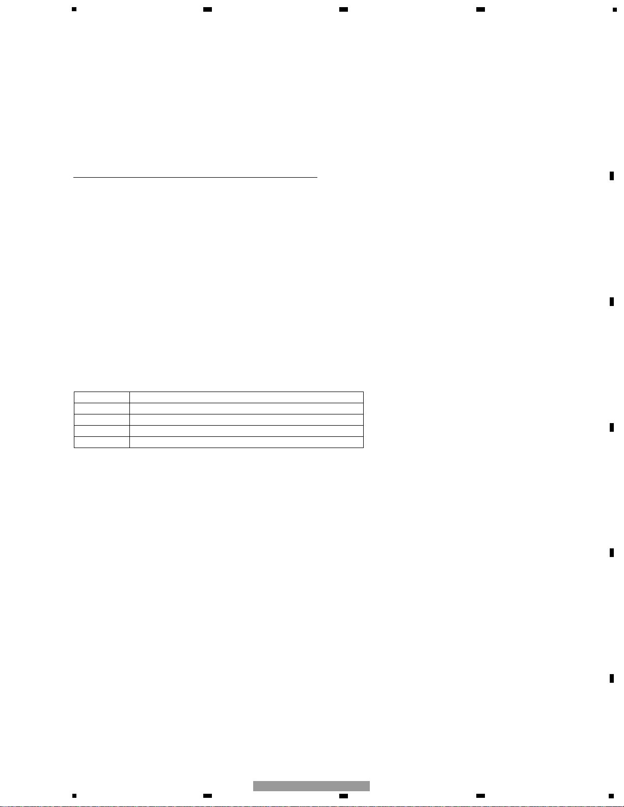
1. SPECIFICATIONS
Power source.............................................................................................................. 14.4 V DC (10.8 — 15.1 V allowable)
Grounding system ............................................................................................................................................ Negative type
Current consumption ........................................................................................................ 19.2 A (at continuous power, 4 Ω)
Average current drawn* .......................................................................................................... 6.7 A (4 Ω for four channels)
10.9 A (4 Ω for two channels)
Fuse .................................................................................................................................................................................. 30 A
Dimensions ........................................................................................................................ 265 (W) × 50 (H) × 237 (D) mm
[10-1/2 (W) × 2 (H) × 9-3/8 (D) in]
Weight ........................................................................................................ 2.8 kg (6.2 lbs) (Leads for wiring not included)
Maximum power output ...................................................................................................................... 70 W × 4 / 200 W × 2
Continuous power output .......................................................... 35 W × 4 (at 14.4 V, 4 Ω, 20 — 20,000 Hz, 0.08% THD)
100 W × 2 (at 14.4 V, 4 Ω, 20 — 20,000 Hz, 0.8% THD)
50 W × 4 (at 14.4 V, 2 Ω, 20 — 20,000 Hz, 0.8% THD)
Load impedance ............................................................................................................................ 4 Ω (2 — 8 Ω allowable)
(Bridge connection: 4 — 8 Ω allowable)
Frequency response ............................................................................................................ 10 — 45,000 Hz (+0 dB, –1 dB)
Signal-to-noise ratio ...................................................................................................................... 100 dB (IHF–A network)
Distortion ............................................................................................................................................ 0.008% (10 W, 1 kHz)
Separation ........................................................................................................................................................ 65 dB (1 kHz)
Low pass filter ................................................................................................................................ Cut off frequency: 80 Hz
Cut off slope: –12 dB/oct
High pass filter .............................................................................................................................. Cut off frequency: 80 Hz
Cut off slope: –12 dB/oct
Maximum input level/impedance .................................................................................... RCA: 6.5 V/22 kΩ (0.2 — 6.5 V)
Speaker: 26 V/40 kΩ (0.8 — 26 V)
Note:
• Specifications and the design are subject to possible modification without notice
due to improvements.
*Average current drawn
• The average current drawn is nearly the maximum current drawn by this unit
when an audio signal is input. Use this value when working out total current
drawn by multiple power amplifiers.
Backup current ................................................................................................................................................. 3.0 mA or less
CONTENTS
SAFETY INFORMATION ............................................2
1. SPECIFICATIONS........................................................3
2. EXPLODED VIEWS AND PARTS LIST.......................4
2.1 PACKING...............................................................4
2.2 EXTERIOR.............................................................6
3. SCHEMATIC DIAGRAM .............................................8
3.1 OVERALL CONNECTION DIAGRAM(GUIDE PAGE)....8
4. PCB CONNECTION DIAGRAM ................................14
4.1 AMP UNIT...........................................................14
5. ELECTRICAL PARTS LIST ........................................18
6. ADJUSTMENT..........................................................20
7. GENERAL INFORMATION .......................................21
7.1 DIAGNOSIS ........................................................21
7.1.1 DISASSEMBLY .........................................21
7.1.2 CONNECTOR FUNCTION DESCRIPTION.......22
7.2 IC ........................................................................23
8. OPERATIONS............................................................24
4
1
234
12
34
F
E
D
C
B
A
GM-X374/XR/UC
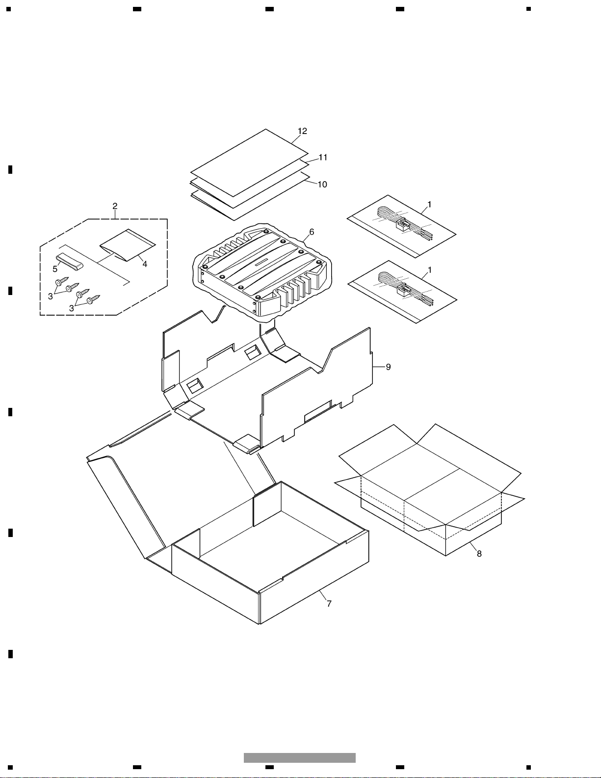
2. EXPLODED VIEWS AND PARTS LIST
2.1 PACKING
5
5
6
7
8
F
E
D
C
B
A
5
6
7
8
GM-X374/XR/UC
1 Cord HDE0044
2 Screw Assy HEA0058
3 Screw BYC40P180FZK
4 Polyethylene Bag HEG0011
5 Cover HNS0101
6 Polyethylene Bag HEG0013
7 Carton HHG0354
8 Contain Box HHL0354
9 Protector HHP0169
10 Owner’s Manual(UC) HRD0219
Owner’s Manual(EW) HRD0221
Owner’s Manual(ES) HRD0224
11 Owner’s Manual(ES) HRD0225
* 12 Warranty Card HRY1157
- PACKING SECTION PARTS LIST
Mark No. Description Part No.
NOTE:
- Parts marked by “*” are generally unavailable because they are not in our Master Spare Parts List.
- Screws adjacent to ∇ mark on the product are used for disassembly.
- For the applying amount of lubricants or glue, follow the instructions in this manual.
( In the case of no amount instructions, apply as you think it appropriate.)
- Owner's Manual
Part No. Language
HRD0219 English, French
HRD0221 English, French, Spanish, German, Italian, Dutch
HRD0224 English, Spanish
HRD0225 Portuguese(B), Arabic
6
1
234
12
34
F
E
D
C
B
A
GM-X374/XR/UC
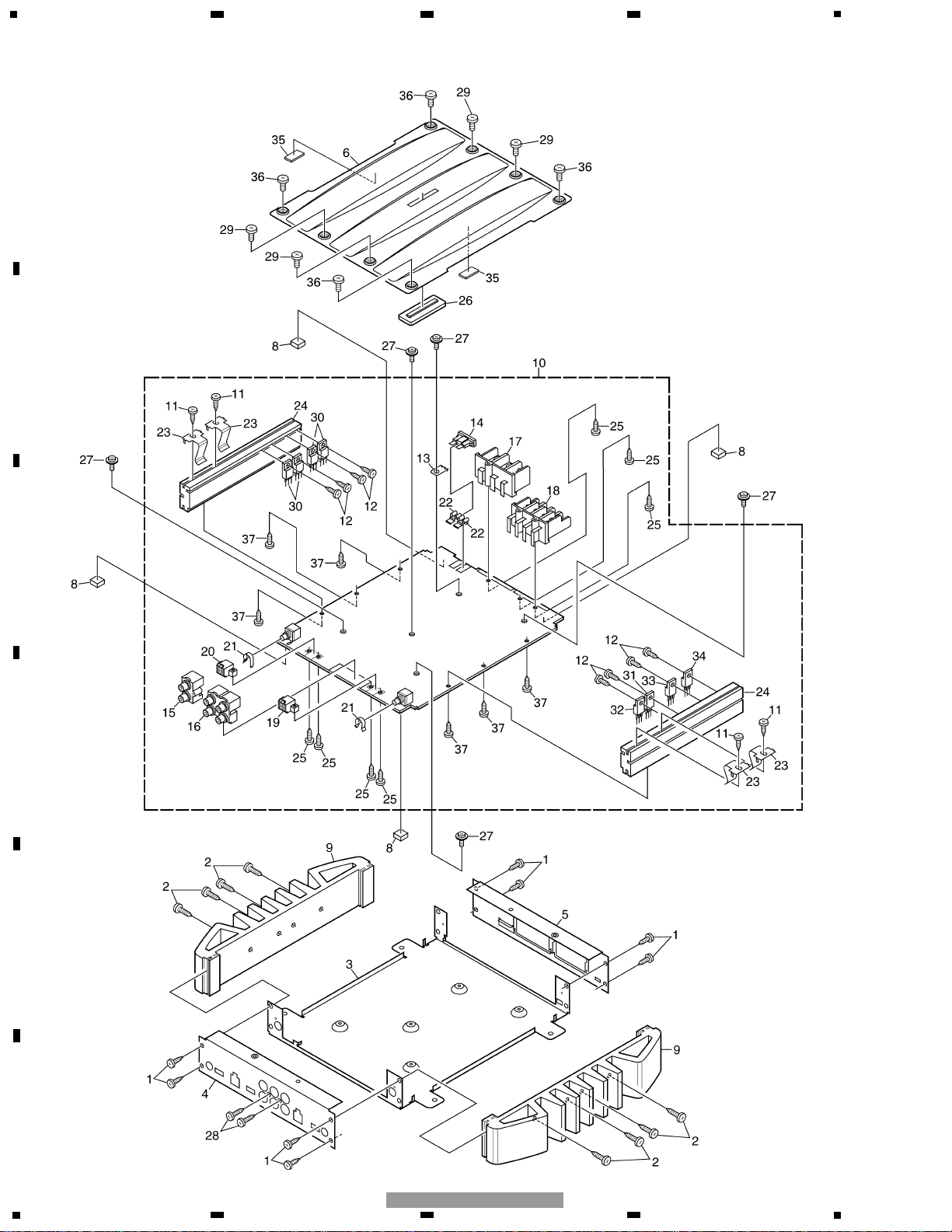
2.2 EXTERIOR

7
5
6
7
8
F
E
D
C
B
A
5
6
7
8
GM-X374/XR/UC
1 Screw BBZ30P060FZK
2 Screw BBZ30P160FZK
3 Chassis HNA0014
4 Panel HNB0188
5 Panel HNB0193
6 Case HNB0195
7 Spacer HNM0006
8 Spacer HNM0124
9 Heat Sink HNR0232
10 Amp Unit(UC) HWH0208
Amp Unit(EW) HWH0209
Amp Unit(ES) HWH0210
11 Screw BBZ30P050FZK
12 Screw BBZ30P080FMC
13 Terminal(CN604) CKF1059
14 Fuse(30A) HEK0030
15 Pin Jack(CN802) HKB0020
16 Pin Jack(CN801) HKB0021
17 Terminal(CN601) HKE0048
18 Terminal(CN851) HKE0052
19 Connector(CN803) HKM1077
20 Connector(CN804) HKM1077
21 Clip HNC0054
22 Holder HNC0082
23 Clip HNC0145
24 Heat Sink HNR0233
25 Screw PPZ30P100FZK
26 Light Pipe Unit HXA0391
27 Screw ISS30P055FUC
28 Screw PPZ30P100FZK
29 Screw HBA0029
30 FET(Q612,613,614,615) STP60NF06FP
31 Transistor(Q660) 2SD2395
32 Transistor(Q661) 2SB1566
33 Diode(D611) FML22R
34 Diode(D612) FML22S
35 Cushion HNM6623
36 Screw HBA0030
37 Screw BBZ30P060FZK
- EXTERIOR SECTION PARTS LIST
Mark No. Description Part No.
8
1
234
12
34
F
E
D
C
B
A
GM-X374/XR/UC
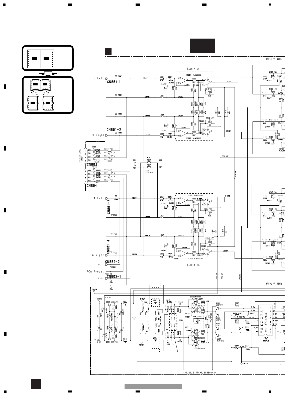
E
EW, ES ONLY
EW, ES ONLY
GAIN = 1
GAIN = -12dB
GAIN = 1
75µH
75µH
INPUT
SELECT
A
AMP UNIT
A-a
A-a A-b
A-a
A-b
A-b
A-a
Large size
SCH diagram
Guide page
Detailed page
UC ONLY
UC ONLY
BEADS CORE
(EW, ES ONLY)
BEADS CORE
(EW, ES ONLY)
3. SCHEMATIC DIAGRAM
3.1 OVERALL CONNECTION DIAGRAM(GUIDE PAGE)
A
 Loading...