

Page 1
GM-5400T/XJ/UC
BRIDGEABLE TWO-CHANNEL POWER AMPLIFIER
ORDER NO.
CRT4251
GM-5400T
GM-5400T
GM-5400T
/XJ/EW5
/XJ/ES
/XJ/UC
For details, refer to "Important Check Points for Good Servicing".
PIONEER CORPORATION 4-1, Meguro 1-chome, Meguro-ku, Tokyo 153-8654, Japan
PIONEER ELECTRONICS (USA) INC. P.O. Box 1760, Long Beach, CA 90801-1760, U.S.A.
PIONEER EUROPE NV Haven 1087, Keetberglaan 1, 9120 Melsele, Belgium
PIONEER ELECTRONICS ASIACENTRE PTE. LTD. 253 Alexandra Road, #04-01, Singapore 159936
PIONEER CORPORATION 2008
K-ZZZ. NOV. 2008 Printed in Japan
Page 2

1234
SAFETY INFORMATION
CAUTION
A
This service manual is intended for qualified service technicians; it is not meant for the casual do-it-yourselfer.
Qualified technicians have the necessary test equipment and tools, and have been trained to properly and safety repair
complex products such as those covered by this manual.
Improperly performed repairs can adversely affect the safety and reliability of the product and may void the warranty.
If you are not qualified to perform the repair of this product properly and safety, you should not risk trying to do so
and refer the repair to a qualified service technician.
WARNING
This product contains certain electrical parts contain chemicals which are known to the State of
California to cause cancer, birth defects or other reproductive harm.
Health & Safety Code Section 25249.6 - Proposition 65
B
Where in a manufacturer’s service documentation, for example in circuit diagrams or lists
of components, a symbol is used to indicate that a specific component shall be replaced only
by the component specified in that documentation for safety reasons, the following symbol shall
be used:
C
D
E
F
2
1234
GM-5400T/XJ/UC
Page 3
5 678
[Important Check Points for Good Servicing]
In this manual, procedures that must be performed during repairs are marked with the below symbol.
Please be sure to confirm and follow these procedures.
1. Product safety
Please conform to product regulations (such as safety and radiation regulations), and maintain a safe servicing environment by
following the safety instructions described in this manual.
1 Use specified parts for repair.
Use genuine parts. Be sure to use important parts for safety.
2 Do not perform modifications without proper instructions.
Please follow the specified safety methods when modification(addition/change of parts) is required due to interferences such as
radio/TV interference and foreign noise.
3 Make sure the soldering of repaired locations is properly performed.
When you solder while repairing, please be sure that there are no cold solder and other debris.
Soldering should be finished with the proper quantity. (Refer to the example)
4 Make sure the screws are tightly fastened.
Please be sure that all screws are fastened, and that there are no loose screws.
5 Make sure each connectors are correctly inserted.
Please be sure that all connectors are inserted, and that there are no imperfect insertion.
6 Make sure the wiring cables are set to their original state.
Please replace the wiring and cables to the original state after repairs.
In addition, be sure that there are no pinched wires, etc.
7 Make sure screws and soldering scraps do not remain inside the product.
Please check that neither solder debris nor screws remain inside the product.
8 There should be no semi-broken wires, scratches, melting, etc. on the coating of the power cord.
Damaged power cords may lead to fire accidents, so please be sure that there are no damages.
If you find a damaged power cord, please exchange it with a suitable one.
9 There should be no spark traces or similar marks on the power plug.
When spark traces or similar marks are found on the power supply plug, please check the connection and advise on secure
connections and suitable usage. Please exchange the power cord if necessary.
a Safe environment should be secured during servicing.
When you perform repairs, please pay attention to static electricity, furniture, household articles, etc. in order to prevent injuries.
Please pay attention to your surroundings and repair safely.
A
B
C
D
2. Adjustments
To keep the original performance of the products, optimum adjustments and confirmation of characteristics within specification.
Adjustments should be performed in accordance with the procedures/instructions described in this manual.
3. Lubricants, Glues, and Replacement parts
Use grease and adhesives that are equal to the specified substance.
Make sure the proper amount is applied.
4. Cleaning
For parts that require cleaning, such as optical pickups, tape deck heads, lenses and mirrors used in projection monitors, proper
cleaning should be performed to restore their performances.
5. Shipping mode and Shipping screws
To protect products from damages or failures during transit, the shipping mode should be set or the shipping screws should be
installed before shipment. Please be sure to follow this method especially if it is specified in this manual.
56
GM-5400T/XJ/UC
E
F
7
8
3
Page 4

1234
CONTENTS
SAFETY INFORMATION..................................................................................................................................... 2
1. SERVICE PRECAUTIONS............................................................................................................................... 5
A
B
1.1 SERVICE PRECAUTIONS ........................................................................................................................ 5
1.2 NOTES ON SOLDERING .......................................................................................................................... 5
2. SPECIFICATIONS............................................................................................................................................ 6
2.1 SPECIFICATIONS ..................................................................................................................................... 6
2.2 PANEL FACILITIES.................................................................................................................................... 8
2.3 CONNECTION DIAGRAM ......................................................................................................................... 9
3. BASIC ITEMS FOR SERVICE........................................................................................................................ 10
3.1 CHECK POINTS AFTER SERVICING..................................................................................................... 10
4. BLOCK DIAGRAM.......................................................................................................................................... 10
5. DIAGNOSIS.................................................................................................................................................... 10
5.1 CONNECTOR FUNCTION DESCRIPTION............................................................................................. 10
6. SERVICE MODE ............................................................................................................................................ 10
7. DISASSEMBLY ...............................................................................................................................................11
8. EACH SETTING AND ADJUSTMENT ............................................................................................................11
9. EXPLODED VIEWS AND PARTS LIST.......................................................................................................... 12
9.1 PACKING ................................................................................................................................................. 12
9.2 EXTERIOR............................................................................................................................................... 14
10. SCHEMATIC DIAGRAM............................................................................................................................... 16
10.1 AMP UNIT(GUIDE PAGE) ..................................................................................................................... 16
11. PCB CONNECTION DIAGRAM.................................................................................................................... 22
11.1 AMP UNIT .............................................................................................................................................. 22
12. ELECTRICAL PARTS LIST.......................................................................................................................... 26
C
D
E
F
4
1234
GM-5400T/XJ/UC
Page 5

5 678
1. SERVICE PRECAUTIONS
1.1 SERVICE PRECAUTIONS
1. You should conform to the regulations governing the product (safety, radio and noise, and other
regulations), and should keep the safety during servicing by following the safety instructions
described in this manual.
2. Be careful in handling ICs. Some ICs such as MOS type are so fragile that they can be damaged by
electrostatic induction.
A
B
1.2 NOTES ON SOLDERING
For environmental protection, lead-free solder is used on the printed circuit boards mounted in this unit.
Be sure to use lead-free solder and a soldering iron that can meet specifications for use with lead-free solders for repairs
accompanied by reworking of soldering.
Compared with conventional eutectic solders, lead-free solders have higher melting points, by approximately 40 C.
Therefore, for lead-free soldering, the tip temperature of a soldering iron must be set to around 373 C in general, although
the temperature depends on the heat capacity of the PC board on which reworking is required and the weight of the tip of
the soldering iron.
Compared with eutectic solders, lead-free solders have higher bond strengths but slower wetting times and higher melting
temperatures (hard to melt/easy to harden).
The following lead-free solders are available as service parts:
Parts numbers of lead-free solder:
GYP1006 1.0 in dia.
GYP1007 0.6 in dia.
GYP1008 0.3 in dia.
C
D
E
56
GM-5400T/XJ/UC
F
7
8
5
Page 6
1234
2. SPECIFICATIONS
2.1 SPECIFICATIONS
A
GM-5400T/XJ/UC
Power source..........................14.4 V DC (10.8 V to 15.1 V
allowable)
Grounding system................ Negative type
Current consumption .......... 30 A (at continuous power,
4 ? )
B
C
D
E
Average current drawn....... 10 A (4
19 A (4
Fuse ......................................... 30 A × 2
Backup current ..................... 0.03 mA or less
Dimensions (W × H × D) ... 265 mm × 62 mm × 346
mm
(10-3/8 in. ×2-1/2 in. × 1 ft.
2 in.)
Weight ..................................... 3.8 kg (Leads for wiring not
included)
Maximum power output ...... 250 W × 2 (4
(4
Continuous power output .. 125 W × 2 (at 14.4 V, 4
Hz to 20 kHz 0.2% THD)
380 W × 1 (at 14.4 V, 4
Hz to 20 kHz 0.8% THD)
190 W × 2 (at 14.4 V, 2
Hz to 20 kHz 0.8% THD)
Load impedance ................... 4
(Bridge connection: 4
Frequency response............ 10 Hz to 50 kHz (+0 dB, –1
dB)
Signal-to-noise ratio............. 95 dB (IHF-A network)
Distortion .................................0.03 % (10 W, 1 kHz)
Separation .............................. 70 dB (1 kHz)
Low pass filter:
Cut off frequency.......... 80 Hz
Cut off slope...................–12 dB/oct
Bass boost:
Frequency....................... 50 Hz
Level................................. 0 dB/6 dB/12 dB
Gain control:
RCA ................................. 200 mV to 6.5 V
Speaker ........................... 0.8 V to 26 V
Maximum input level / impedance:
RCA ................................. 6.5 V / 22 k
Speaker ........................... 26 V / 90 k
for two channels)
for one channel)
)/760W×1
)
,20
(2 to 8 allowable)
to 8
allowable)
,20
,20
CEA2006 Specifications
Power output ......................... 125 W RMS × 2 Channels
(at 14.4 V, 4
THD+N)
380 W RMS × 1 Channels
(at 14.4 V, 4
1 % THD+N)
190 W RMS × 2 Channels
(at 14.4 V, 2
THD+N)
S/N ratio .................................. 75 dBA (reference: 1 W into
4
)
and 1%
BRIDGE and
and 1%
Notes
• Specifications and the design are subject to
modifications without notice due to improvements.
• The average current drawn is nearly the maximum current drawn by this unit when an
audio signal is input. Use this value when
working out total current drawn by multiple
power amplifiers.
F
6
1234
GM-5400T/XJ/UC
Page 7
5 678
GM-5400T/XJ/EW5, GM-5400T/XJ/ES
Power source..........................14.4 V DC (10.8 V to 15.1 V
allowable)
Grounding system................. Negative type
Current consumption .......... 30 A (at continuous power,
4
)
Average current drawn....... 10 A (4
19 A (4
Fuse ........................................ 30 A × 2
Backup current ..................... 0.03 mA or less
Dimensions (W × H × D) ... 265 mm × 62 mm × 346
mm
Weight ..................................... 3.8 kg(Leads for wiring not
included)
Maximum power output ...... 250 W × 2 (4
(4
Continuous power output .. 125 W × 2 (at 14.4 V, 4
Hz to 20 kHz 0.2% THD)
380 W × 1 (at 14.4 V, 4
Hz to 20 kHz 0.8% THD)
190 W × 2 (at 14.4 V, 2
Hz to 20 kHz 0.8% THD)
Load impedance ................... 4
(Bridge connection: 4
Frequency response............ 10 Hz to 50 kHz (+0 dB, –1
dB)
Signal-to-noise ratio............. 95 dB (IEC -A network)
Distortion .................................0.03 % (10 W, 1 kHz)
Separation .............................. 70 dB (1 kHz)
Low pass filter:
Cut off frequency.......... 80 Hz
Cut off slope...................–12 dB/oct
Bass boost:
Frequency...................... 50 Hz
Level................................ 0 dB/6 dB/12 dB
Gain control:
RCA ................................. 200 mV to 6.5 V
Speaker ........................... 0.8 V to 26 V
Maximum input level / impedance:
RCA ................................. 6.5 V / 22 k
Speaker ........................... 26 V / 90 k
Notes
• Specifications and the design are subject to
modifications without notice due to improvements.
• The average current drawn is nearly the maxi-
mum current drawn by this unit when an
audio signal is input. Use this value when
for two channels)
for one channel)
) / 760 W × 1
)
(2 to 8 allowable)
to 8
allowable)
,20
,20
,20
A
working out total current drawn by multiple
power amplifiers.
B
C
D
E
56
GM-5400T/XJ/UC
F
7
8
7
Page 8
1234
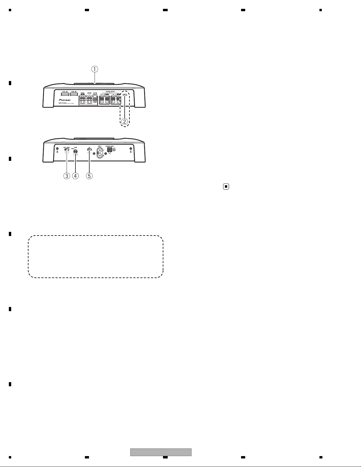
2.2 PANEL FACILITIES
A
What ’s what
NORMAL position. For use with an RCA
equipped Pioneer car stereo, with max.
Front side
output of 4 V or more, adjust level to
match that of the car stereo output.
• If you hear too much noise when using
the speaker input terminals, turn the
gain control to higher level.
5 LPF (low-pass filter) switch
B
Rear side
(EW5, ES)
Switch the settings based on the connected
speaker.
• When the Subwoofer is connected:
Select ON . This eliminates high range
frequency and outputs low range frequency.
• When the full range speaker is connected:
Select OFF. OFF outputs the entire fre-
To adjust the switch, use a flathead screwdri-
C
ver if needed.
quency range.
1 Power indicator
The power indicator lights up to indicate
power ON.
(EW5, ES)
2 BFC (beat frequency control) switch
Located front side the unit. If beats are audible while listening to MW/LW broadcasts via
car stereo, change the BFC switch using a
D
small flathead screwdriver.
3 BASS BOOST (bass boost level control)
switch
You can select a bass boost level from 0 dB,
6 dB and 12 dB.
4 GAIN (gain) control
If output remains low, even when the car
E
stereo volume is turned up, turn controls to
lower level. If distortion occurs when the car
stereo volume is turned up, turn these controls to higher level.
• For use with an RCA equipped car stereo
(standard output of 500 mV), set to the
F
8
1234
GM-5400T/XJ/UC
Page 9
5 678
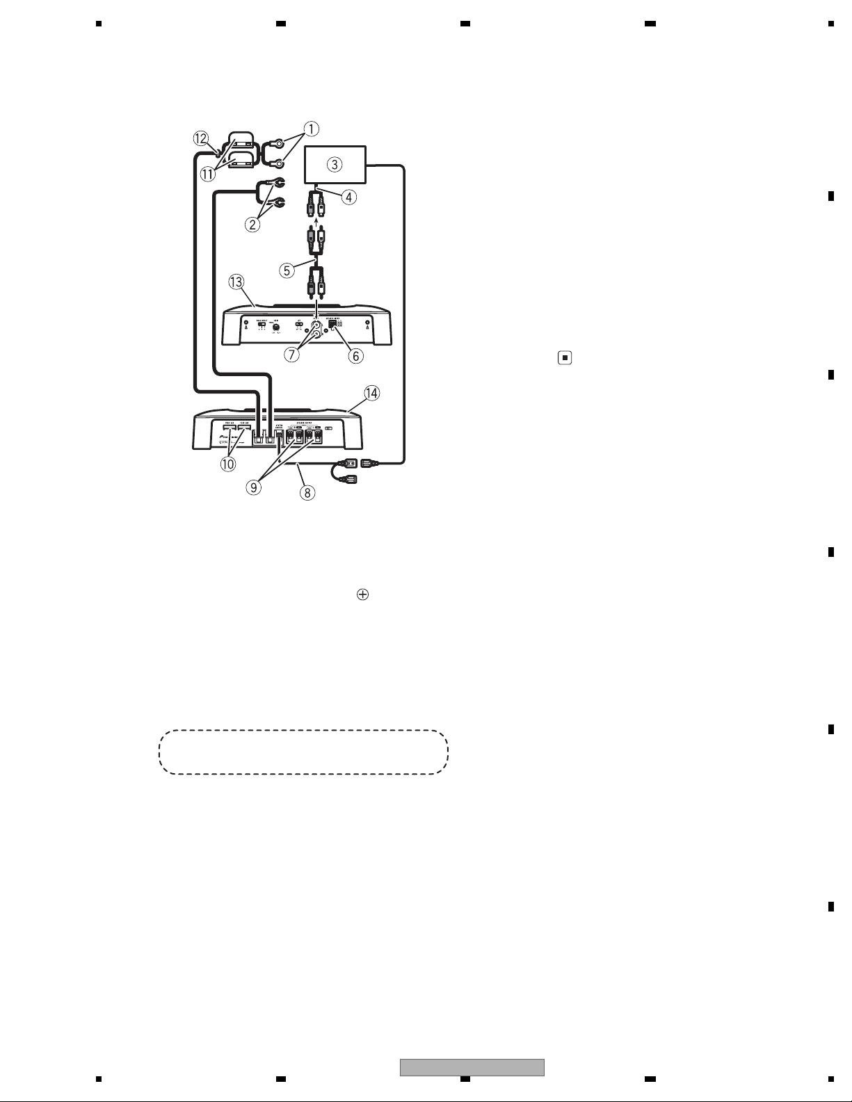
2.3 CONNECTION DIAGRAM
8 System remote control wire (sold separately)
Connect male terminal of this wire to the system remote control terminal of the car stereo
(SYSTEM REMOTE CONTROL ). The female
terminal can be connected to the auto-antenna relay control terminal. If the car stereo
lacks a system remote control terminal, connect the male terminal to the power terminal
via the ignition switch.
9 Speaker output terminals
a Fuse (30 A) × 2
b Fuse (30 A) × 2
c Grommet
d Rear side
e Front side
A
B
C
1 Special red battery wire
RD-223 (sold separately)
After completing all other amplifier connections, finally connect the battery wire terminal
of the amplifier to the positive (
) battery
terminal.
2 Ground wire (Black)
RD-223 (sold separately)
Connect to metal body or chassis.
3 Car stereo with RCA output jacks (sold sepa-
rately)
4 External output
If only one input plug is used, do not connect
anything to RCA input jack B.
(ES)
5 Connecting wire with RCA pin plugs (sold se-
parately)
6 Speaker input terminal
7 RCA input jack
D
E
56
GM-5400T/XJ/UC
F
7
8
9
Page 10

1234
3. BASIC ITEMS FOR SERVICE
3.1 CHECK POINTS AFTER SERVICING
A
To keep the product quality after servicing, please confirm following check points.
1 Confirm whether the customer complain has
been solved.
2 Check the output sound. Audio and operations must be normal.
B
See the table below for the items to be checked regarding video and audio:
Item to be checked regarding audio
Distortion
Noise
Volume too low
Volume too high
Volume fluctuating
Sound interrupted
demrifnocebotmetIserudecorP.oN
The customer complain must not be
reappeared.
Audio and operations must be normal.
retfaecnaraeppastinotridrosehctarcsoNkcehcecnaraeppA3
receiving it for service.
C
4. BLOCK DIAGRAM
There is not information to be shown in this chapter.
5. DIAGNOSIS
5.1 CONNECTOR FUNCTION DESCRIPTION
D
E
F
6. SERVICE MODE
10
1234
There is not information to be shown in this chapter.
GM-5400T/XJ/UC
Page 11

7. DISASSEMBLY
-
Removing the Chassis (Fig.1)
Remove the two screws.
1
Remove the six screws
2
and then remove the Chassis.
5 678
Chassis
2
2
A
2
-
Removing the Amp Unit (Fig.2)
Remove the twenty four screws
1
and then remove the Chassis.
Amp Unit
1
2
2
1 1
1
1
1
1
B
2
Fig.1
1
1
1
1
C
1
1
1
1
1
1
1
1
1
1
1
1
1
1
1
Fig.2
D
Bonding Position
GYL1006
8. EACH SETTING AND ADJUSTMENT
56
There is not information to be shown in this chapter.
GM-5400T/XJ/UC
E
F
7
8
11
Page 12

1234
N
9. EXPLODED VIEWS AND PARTS LIST
OTES : Parts marked by " * " are generally unavailable because they are not in our Master Spare Parts List.
The > mark found on some component parts indicates the importance of the safety factor of the part.
A
Therefore, when replacing, be sure to use parts of identical designation.
Screw adjacent to mark on the product are used for disassembly.
For the applying amount of lubricants or glue, follow the instructions in this manual.
(In the case of no amount instructions,apply as you think it appropriate.)
9.1 PACKING
B
""
C
D
E
F
12
1234
GM-5400T/XJ/UC
Page 13

5 678
(1) PACKING SECTION PARTS LIST
No. Description Part No.
Mark No. Description Part No.
* 1-1 Caution Card See Contrast table (2)
* 1-2 Warranty Card See Contrast table (2)
1-3 Owner's Manual See Contrast table (2)
2 Cord Assy CZD5517
3 Polyethylene Bag CZE2962
4 Polyethylene Bag See Contrast table (2)
Mark
5 Unit Box See Contrast table (2)
6 Contain Box See Contrast table (2)
7 Cushion CZH6698
8 Screw Assy CEA5330
9 Screw BYC40P180FTB
* 10 Polyethylene Sheet CNM4338
(2) CONTRAST TABLE
GM-5400T/XJ/UC, GM-5400T/XJ/EW5 and GM-5400T/XJ/ES are constructed the same except for the following:
Mark No. Description GM-5400T/XJ/UC GM-5400T/XJ/EW5 GM-5400T/XJ/ES
* 1-1 Caution Card CZR5560 Not used Not used
* 1-2 Warranty Card CRY1276 CRY1279 Not used
1-3 Owner's Manual CZR5552 CZR5551 CZR5553
4 Polyethylene Bag CEG1351 *CZE2987 *CZE2987
5 Unit Box CZH6684 CZH6682 CZH6686
6 Contain Box CZH6685 CZH6683 CZH6687
Owner's Manual,Installation Manual
Part No. Language
A
B
CZR5552 English, French, Spanish(Espanol)
CZR5551 English, Spanish(Espanol), German, French, Italian, Dutch, Russian
CZR5553 English, Spanish(Espanol), Portuguese(B), Arabic
C
D
E
56
GM-5400T/XJ/UC
F
7
8
13
Page 14

1234
9.2 EXTERIOR
A
B
A
C
B
D
B
E
A
F
14
1234
GM-5400T/XJ/UC
Page 15

5 678
(1) EXTERIOR SECTION PARTS LIST
Mark No. Description Part No.
1 Screw BBZ30P100FTC
2 Screw BBZ30P120FTC
* 3 Screw See Contrast table (2)
4 Screw BSZ26P060FTB
5 Screw BSZ30P060FTB
6 Holder See Contrast table (2)
7 Plate CZN8435
8 Plate CZN8438
9 Spacer CZN8440
10 Chassis CZN8441
11 Amp Unit See Contrast table (2)
12 Screw BBZ30P080FTB
13 Screw BBZ30P100FTC
> 14 Fuse(30 A) CEK1330
15 Pin Jack(JA101) CKB1068
16 Terminal(JA801) CKE1055
17 Terminal(JA501) CKE1057
18 Terminal(JA502) CKE1057
19 Terminal(JA802) CND2458
20 Terminal(JA803) CND2458
21 Terminal(JA804) CND2458
22 Terminal(JA805) CND2458
* 23 Bas Bar(1) CZN8425
* 24 Bas Bar(5) CZN8429
* 25 Bas Bar(3) CZN8427
26 Holder CZN8430
* 27 Heat Sink CZN8432
No. Description Part No.
Mark
* 28 Heat Sink CZN8433
29 Sheet CZN8443
30 Screw PPZ30P100FNN
31 Case Unit See Contrast table (2)
32 Screw BBZ30H060FTB
* 33 Heat Sink See Contrast table (2)
34 Plate Assy See Contrast table (2)
35 Nut See Contrast table (2)
36 Screw PPZ30P100FTB
* 37 Washer See Contrast table (2)
38 Transistor(Q515,516) KTC3114
39 Transistor(Q523,524,525,526) 2SC5358
40 Transistor(Q527,528,529,530) 2SA1986
41 Transistor(Q805,806,807,808,809,810) FKV550N
42 Transistor(Q811) KTC2026
43 Transistor(Q812) KTA1046
44 Thermistor(TH701,702) CCX1057
45 Diode(D801) FML22S
46 Diode(D802) FML22R
47 Socket(J1) CKM1463
* 48 Seal CAN3984
49 Screw BBZ30P080FTB
50 Screw PPZ30P100FTB
51 Plate CZN8417
52 Earth Terminal(KN801) CZK2969
53 Screw PBZ30P120FTB
A
B
C
(2) CONTRAST TABLE
GM-5400T/XJ/UC, GM-5400T/XJ/EW5 and GM-5400T/XJ/ES are constructed the same except for the following:
Mark No. Description GM-5400T/XJ/UC GM-5400T/XJ/EW5 GM-5400T/XJ/ES
* 3 Screw BMZ40P250FTB Not used Not used
6 Holder CNV8522 Not used Not used
7 Plate CZN8435 CZN8435 CZN8435
11 Amp Unit CZW5578 CZW5577 CZW5577
31 Case Unit CZX6645 CZX6644 CZX6646
* 33 Heat Sink CZN8444 CZN8416 CZN8416
34 Plate Assy CZX6639 CZX6638 CZX6639
35 Nut NB40FTB Not used Not used
* 37 Washer WB45FTB Not used Not used
D
E
F
56
GM-5400T/XJ/UC
7
8
15
Page 16

1234
10. SCHEMATIC DIAGRAM
10.1 AMP UNIT(GUIDE PAGE)
A
Note: When ordering service parts, be sure to refer to " EXPLODED VIEWS AND PARTS LIST" or
"ELECTRICAL PARTS LIST".
A-a A-b
A-a
A-b
Large size
SCH diagram
Guide page
NOTE :
For resistors and capacitors in the circuit diagrams, their resistance values or
capacitance values are expressed in codes:
Ex. *Resistors
Code Practical value
123 12 k ohms
103 10 k ohms
A-a
*Capacitors
Code Practical value
103 0.01 uF
101/10 100 uF/10 V
A-b
Detailed page
A-a
B
C
D
E
D-D converter output voltage (VH)-1 + 36.5 + 3 V Sp out : 1 kHz, 1 W
D-D converter output voltage (VD)-1 + 44.5 + 3 V Sp out : 1 kHz, 1 W
D-D converter output voltage (VH)-2 + 36.5 + 5 V Rg=1 kohm Referred value
D-D converter output voltage (VD)-2 + 34.5 + 5 V Rg=1 kohm Referred value
- 36.5 + 3 V
- 44.5 + 3 V
- 39.5 + 5 V
- 36.5 + 5 V
F
A
16
1234
GM-5400T/XJ/UC
Page 17

5 678
A
A-b
NM : No Mount
The > mark found on some component parts indicates
the importance of the safety factor of the part.
Therefore, when replacing, be sure to use parts of
identical designation.
A
AMP UNIT
B
BFC
C
D
EW5,ES
E
>
56
GM-5400T/XJ/UC
>
F
A
7
8
17
Page 18

1234
A
AMP UNIT
A
B
C
A-a A-b
D
E
F
A-b
18
The > mark found on some component parts indicates
the importance of the safety factor of the part.
Therefore, when replacing, be sure to use parts of
NM : No Mount
identical designation.
GM-5400T/XJ/UC
1234
Page 19

5 678
>
>
A
B
C
EW5,ES
BFC
A-a A-b
D
E
56
GM-5400T/XJ/UC
F
A-b
7
8
19
Page 20

A
B
1234
A-b
C
*Capacitors
Code Practical value
103 0.01 uF
A-bA-a
D
For resistors and capacitors in the circuit diagrams, their resistance values or
capacitance values are expressed in codes:
NOTE :
E
101/10 100 uF/10 V
Ex. *Resistors
Code Practical value
123 12 k ohms
103 10 k ohms
F
A-a
20
1234
GM-5400T/XJ/UC
Page 21

5 678
A-b
A
B
C
- 36.5 + 3 V
- 44.5 + 3 V
- 39.5 + 5 V
- 36.5 + 5 V
A-bA-a
D
E
56
GM-5400T/XJ/UC
D-D converter output voltage (VH)-1 + 36.5 + 3 V Sp out : 1 kHz, 1 W
D-D converter output voltage (VD)-1 + 44.5 + 3 V Sp out : 1 kHz, 1 W
D-D converter output voltage (VH)-2 + 36.5 + 5 V Rg=1 kohm Referred value
D-D converter output voltage (VD)-2 + 34.5 + 5 V Rg=1 kohm Referred value
F
A-a
7
8
21
Page 22

1234
11. PCB CONNECTION DIAGRAM
11.1 AMP UNIT
A
B
C
NOTE FOR PCB DIAGRAMS
1.The parts mounted on this PCB
include all necessary parts for
several destination.
For further information for
respective destinations, be sure
to check with the schematic dia gram.
2.Viewpoint of PCB diagrams
Connector
P.C.Board
Capacitor
Chip Part
SIDE A
SIDE B
AMP UNIT
A
D
E
F
22
A
GM-5400T/XJ/UC
1234
Page 23

5 678
SIDE A
A
B
C
D
E
FRONT
F
56
GM-5400T/XJ/UC
A
7
8
23
Page 24

1234
A
AMP UNIT
A
B
C
D
E
F
A
24
1234
GM-5400T/XJ/UC
Page 25

5 678
SIDE B
A
B
C
D
E
F
56
GM-5400T/XJ/UC
A
7
8
25
Page 26

1234
12. ELECTRICAL PARTS LIST
NOTE:
A
Parts whose parts numbers are omitted are subject to being not supplied.
The part numbers shown below indicate chip components.
Chip Resistor
RS1/_S___J,RS1/__S___J
Chip Capacitor (except for CQS.....)
CKS....., CCS....., CSZS.....
The > mark found on some component parts indicates the importance of the safety factor of the part.
Therefore, when replacing, be sure to use parts of identical designation.
Meaning of the figures and others in the parentheses in the parts list.
B
Example) IC 301 is on the point (face A, 91 of x-axis, and 111 of y-axis) of the corresponding
PC board.
IC 301 (A, 91, 111) IC NJM2068V
The expression of the unit in this manual is shown by u instead of µ. Please do not make a mistake.
Circuit Symbol and No. Part No.
A
Unit Number : CZW5578(UC)
Unit Number : CZW5577(EW5,ES)
C
Unit Name : Amp Unit
MISCELLANEOUS
IC 101 IC NJM2068MD
IC 102 IC NJM2068MD
IC 301 IC NJM4558MD
IC 701 IC NJM4558MD
IC 801 IC UPC494GS
IC 901 IC NJM4558MD
IC 902 IC NJM4558MD
D
Q 301 Transistor KRC285S
Q 302 Transistor KRC285S
Q 501 Transistor 2SA1037K
Q 502 Transistor 2SA1037K
Q 503 Transistor 2SC2412K
Q 504 Transistor 2SC2412K
Q 505 Transistor 2SA1037K
Q 506 Transistor 2SA1037K
Q 507 Transistor 2SC2412K
Q 508 Transistor 2SC2412K
Q 509 Transistor 2SC2412K
E
Q 510 Transistor 2SC2412K
Q 511 Transistor 2SA1038S
Q 512 Transistor 2SA1038S
Q 513 Transistor 2SC2389S
Q 514 Transistor 2SC2389S
Q 515 Transistor KTC3114
Q 516 Transistor KTC3114
Q 517 Transistor KTD600K
Q 518 Transistor KTD600K
Q 519 Transistor KTB631K
F
Q 520 Transistor KTB631K
Q 521 Transistor KTC3911S
Q 522 Transistor KTC3911S
26
1234
Circuit Symbol and No. Part No.
Q 523 Transistor 2SC5358
Q 524 Transistor 2SC5358
Q 525 Transistor 2SC5358
Q 526 Transistor 2SC5358
Q 527 Transistor 2SA1986
Q 528 Transistor 2SA1986
Q 529 Transistor 2SA1986
Q 530 Transistor 2SA1986
Q 701 Transistor 2SC2412K
Q 702 Transistor 2SC2412K
Q 703 Transistor KTA1504S
Q 704 Transistor KTC3875S
Q 705 Transistor KN2907AS
Q 706 Transistor KTA1504S
Q 707 Transistor KTC3875S
Q 708 Transistor 2SA1037K
Q 709 Transistor KTA1504S
Q 710 Transistor KTC3875S
Q 711 Transistor KTC3875S
Q 712 Transistor 2SA1037K
Q 750 Transistor KRA102S
Q 801 Transistor 2SC2411K
Q 802 Transistor 2SA1036K
Q 803 Transistor 2SA1036K
Q 804 Transistor 2SC2411K
Q 805 Transistor FKV550N
Q 806 Transistor FKV550N
Q 807 Transistor FKV550N
Q 808 Transistor FKV550N
Q 809 Transistor FKV550N
Q 810 Transistor FKV550N
Q 811 Transistor KTC2026
Q 812 Transistor KTA1046
D 101 Diode 1SS355
D 102 Diode 1SS355
D 103 Diode 1SS355
D 104 Diode 1SS355
D 105 Diode 1SS355
D 106 Diode 1SS355
D 107 Diode 1SS355
GM-5400T/XJ/UC
Page 27

5 678
Circuit Symbol and No. Part No.
D 108 Diode 1SS355
D 501 Diode KDS4148U
D 502 Diode KDS4148U
D 503 Diode KDS4148U
D 504 Diode KDS4148U
D 505 Diode MA111
D 506 Diode MA111
D 701 Diode UDZS7R5(B)
D 702 Diode UDZS16(B)
D 703 Diode KDS4148U
D 704 Diode KDZ8R2V(Y)
D 705 Diode KDS4148U
D 706 Diode KDS4148U
D 707 Diode KDS4148U
D 708 Diode UDZS3R6(B)
D 709 Diode KDS4148U
D 710 Diode KDS4148U
D 711 Diode KDS4148U
D 751 Diode UDZS6R8(B)
D 752 Diode UDZS4R7(B)
D 801 Diode FML22S
D 802 Diode FML22R
D 803 Diode EP05FA20
D 804 Diode EP05FA20
D 805 Diode MTZJ16(B)
D 806 Diode MTZJ16(B)
D 841 Diode RM4Z-LFJ4
D 842 LED NHSB046AT
L 801 Choke Coil 45 uH CZT2939
L 802 Choke Coil 105 uH CZT2938
L 803 Choke Coil 105 uH CZT2938
T 801 Transformer CZT2940
TH701 Thermistor CCX1057
TH702 Thermistor CCX1057
TH703 Posistor CZC2982
S 301 Switch(OFF/LPF) CZS2928
S 801 Switch(BFC)(EW5,ES) CZS2927
S 901 Switch(OFF/6dB/12dB) CZS2929
VR301 Variable Resistor 10 kohm CZC2975
RESISTORS
R 101 RS1/16S471J
R 102 RS1/16S471J
R 103 RS1/16S223J
R 104 RS1/16S223J
R 105 10 kohm CCN1152
R 106 10 kohm CCN1152
R 107 10 kohm CCN1152
R 108 10 kohm CCN1152
R 109 10 kohm CCN1152
R 110 10 kohm CCN1152
R 111 10 kohm CCN1152
R 112 10 kohm CCN1152
R 113 RS1/16S0R0J
R 114 RS1/16S0R0J
R 115 RS1/16S0R0J
R 116 RS1/16S0R0J
R 117 RS1/16S103J
R 118 RS1/16S103J
R 121 RS1/8S683J
56
R 122 RS1/8S683J
R 123 RS1/10S2R2J
R 124 RS1/10S2R2J
R 301 RS1/16S222J
R 302 RS1/16S222J
R 303 RS1/16S103J
R 304 RS1/16S103J
R 305 RS1/16S912J
R 306 RS1/16S912J
R 307 RS1/16S912J
R 308 RS1/16S912J
R 309 RS1/16S222J
R 310 RS1/16S222J
R 311 RS1/16S560J
R 312 RS1/16S560J
R 313 RS1/16S103J
R 314 RS1/16S103J
R 501 RS1/16S103J
R 502 RS1/16S103J
R 503 RS1/16S473J
R 504 RS1/16S473J
R 505 RS1/16S331J
R 506 RS1/16S331J
R 507 RS1/16S331J
R 508 RS1/16S331J
R 509 RS1/16S681J
R 510 RS1/16S681J
R 511 RS1/16S681J
R 512 RS1/16S681J
R 513 RS1/16S361J
R 514 RS1/16S361J
R 515 RS1/10S433J
R 516 RS1/10S433J
R 517 RD1/2PM223J
R 518 RD1/2PM223J
R 519 RS1/8S101J
R 520 RS1/8S101J
R 521 RS1/16S121J
R 522 RS1/16S121J
R 523 RS1/16S182J
R 524 RS1/16S182J
R 525 RS1/16S681J
R 526 RS1/16S681J
R 527 RS1/16S181J
R 528 RS1/16S181J
R 529 RS1/16S100J
R 530 RS1/16S100J
R 531 RS1/16S100J
R 532 RS1/16S100J
R 533 0.1 ohm(3 W) CZC2973
R 534 0.1 ohm(3 W) CZC2973
R 535 0.1 ohm(3 W) CZC2973
R 536 0.1 ohm(3 W) CZC2973
R 537 RS1/16S473J
R 538 RS1/16S473J
R 539 RD1/2PM100J
R 540 RD1/2PM100J
R 541 RS1/16S473J
R 542 RS1/16S473J
R 543 RS1/16S564J
GM-5400T/XJ/UC
Circuit Symbol and No. Part No.
7
8
A
B
C
D
E
F
27
Page 28

1234
Circuit Symbol and No. Part No.
R 544 RS1/16S564J
Circuit Symbol and No. Part No.
R 753 RS1/16S182J
R 547 RD1/2PM100J
R 548 RD1/2PM100J
A
R 549 RD1/2PM100J
R 550 RD1/2PM100J
R 551 RD1/2PM100J
R 552 RD1/2PM100J
R 553 RD1/2PM100J
R 554 RD1/2PM100J
R 555 0.1 ohm(3 W) CZC2973
R 556 0.1 ohm(3 W) CZC2973
R 557 0.1 ohm(3 W) CZC2973
R 558 0.1 ohm(3 W) CZC2973
R 559 RS1/16S473J
B
R 560 RS1/16S473J
R 561 RS1/16S221J
R 562 RS1/16S221J
R 701 2.2 kohm(1/4 W) CZC2980
R 702 RS1/16S473J
R 703 RS1/16S103J
R 704 RS1/16S103J
R 705 RS1/16S332J
R 706 RS1/16S472J
R 707 RS1/16S222J
R 708 RS1/16S472J
C
R 709 560 ohm(1/4 W) CZC2981
R 754 RS1/16S202J
R 756 RS1/16S334J
R 757 RS1/16S103J
R 758 RS1/16S103J
R 801 RS1/16S153J
R 802 (EW5,ES) RS1/16S105J
R 803 RS1/16S332J
R 804 RS1/16S332J
R 805 RS1/16S472J
R 806 RS1/16S472J
R 807 RS1/16S472J
R 808 RS1/16S473J
R 809 RS1/16S102J
R 810 RS1/16S153J
R 811 RS1/16S124J
R 812 RS1/16S103J
R 813 RD1/2PM121J
R 814 RD1/2PM121J
R 815 RD1/2PM121J
R 817 RD1/2PM121J
R 818 RD1/2PM121J
R 819 RD1/2PM121J
R 820 RS1/16S472J
R 821 RS1/16S472J
R 822 RD1/2PM220J
R 710 RS1/16S393J
R 711 RS1/16S393J
R 712 RS1/16S153J
R 713 RS1/16S102J
R 714 RS1/16S103J
R 715 RS1/16S152J
R 716 RS1/16S332J
R 717 RS1/16S101J
R 718 RS1/16S103J
D
R 719 RS1/16S103J
R 720 RS1/16S223J
R 721 RS1/16S472J
R 722 RS1/16S223J
R 723 RS1/10S222J
R 724 RS1/16S183J
R 725 RS1/16S102J
R 726 RS1/16S153J
R 727 RS1/10S221J
R 728 RS1/16S223J
R 729 RS1/16S103J
E
R 730 RS1/16S123J
R 731 RS1/16S273J
R 732 RS1/16S123J
R 733 RS1/16S682J
R 734 RS1/16S163J
R 735 RS1/16S123J
R 736 RS1/16S102J
R 737 RS1/16S331J
R 738 RS1/16S473J
R 742 RS1/16S334J
F
R 743 RS1/16S472J
R 750 RS1/16S513J
R 751 RS1/16S473J
R 752 RS1/16S332J
28
1234
R 823 RD1/2PM220J
R 824 RD1/2PM220J
R 827 RD1/2PM391J
R 828 RD1/2PM391J
R 831 10 kohm(1/4 W) CZC2979
R 832 10 kohm(1/4 W) CZC2979
R 833 RS1/16S102J
R 834 RS1/16S132J
R 901 RS1/16S182J
R 902 RS1/16S182J
R 903 RS1/16S104J
R 904 RS1/16S104J
R 905 RS1/16S132J
R 906 RS1/16S132J
R 907 RS1/16S221J
R 908 RS1/16S221J
R 909 RS1/16S331J
R 910 RS1/16S331J
R 911 RS1/16S273J
R 912 RS1/16S273J
CAPACITORS
C 101 CCSRCH471J50
C 102 CCSRCH471J50
C 105 CCSRCH470J50
C 106 CCSRCH470J50
C 107 CCSRCH470J50
C 108 CCSRCH470J50
C 109 CFTLA223J50
C 110 CFTLA223J50
C 111 CEAT330M16
C 112 CEAT330M16
C 113 CCSRCH221J50
GM-5400T/XJ/UC
Page 29

5 678
Circuit Symbol and No. Part No.
C 114 CCSRCH221J50
C 305 CFTLA274J50
C 306 CFTLA274J50
C 307 CFTLA154J50
C 308 CFTLA154J50
C 501 CEAT101M16
C 502 CEAT101M16
C 503 CCSRCH680J50
C 504 CCSRCH680J50
Circuit Symbol and No. Part No.
C 820 2 200 uF/50 V CZC2976
C 821 2 200 uF/50 V CZC2976
C 822 2 200 uF/50 V CZC2976
C 823 CEAT470M25
C 824 CEAT470M25
C 825 CEAT470M25
C 826 CEAT470M25
C 827 CKSRYB333K50
C 828 CKSRYB333K50
A
C 505 CCSRCH471J50
C 506 CCSRCH471J50
C 507 CEAT101M16
C 508 CEAT101M16
C 509 CCSRCH150J50
C 510 CCSRCH150J50
C 511 CCSRCH220J50
C 512 CCSRCH220J50
C 513 CCSRCH220J50
C 514 CCSRCH220J50
C 515 CFTLA223J50
C 516 CFTLA223J50
C 517 CCSRCH220J50
C 518 CCSRCH220J50
C 519 CCSRCH220J50
C 520 CCSRCH220J50
C 521 CCSRCH220J50
C 522 CCSRCH220J50
C 523 CCSRCH220J50
C 524 CCSRCH220J50
C 525 CKSRYB333K50
C 526 CKSRYB333K50
C 527 CQMA102J50
C 528 CQMA102J50
C 531 CKSRYB103K50
C 831 CCSRCH222J50
C 841 CFTLA224J50
C 843 CCSQCH103J50
C 901 CFTLA273J50
C 902 CFTLA273J50
C903 CEANP4R7M50
C904 CEANP4R7M50
C 905 CFTLA224J50
C 906 CFTLA224J50
B
C
C 532 CKSRYB103K50
C 702 CKSRYB103K50
C 703 CEJQ100M50
C 704 CEAT101M16
C 705 CEANP470M16
C 706 CKSRYB104K50
C 707 CEJQ220M16
C 708 CEJQ220M16
C 709 CEAT331M25
C 710 CKSRYB103K50
C 711 CEAT221M16
C 801 CCSRCH102J50
C 802 CEAT101M16
C 803 CKSRYB103K50
C 804 CKSQYB225K10
C 805 CEAT221M16
C 806 CFTLA564J50
C 807 CKSRYB224K16
C 808 CKSRYB472K50
C 809 CKSRYB472K50
C 810 3 300 uF/16 V CZC2977
C 811 3 300 uF/16 V CZC2977
C 812 CCSRCH222J50
C 815 CEAT221M50
C 816 CEAT221M50
D
E
F
C 819 2 200 uF/50 V CZC2976
56
GM-5400T/XJ/UC
7
8
29
 Loading...