

Page 1

PIONEER CORPORATION 4-1, Meguro 1-chome, Meguro-ku, Tokyo 153-8654, Japan
PIONEER ELECTRONICS (USA) INC. P.O. Box 1760, Long Beach, CA 90801-1760, U.S.A.
PIONEER EUROPE NV Haven 1087, Keetberglaan 1, 9120 Melsele, Belgium
PIONEER ELECTRONICS ASIACENTRE PTE. LTD. 253 Alexandra Road, #04-01, Singapore 159936
PIONEER CORPORATION 2009
GM-3400T/XJUC
BRIDGEABLE TWO-CHANNEL POWER AMPLIFIER
ORDER NO.
CRT4513
GM-3400T
GM-3400T
GM-3400T
/XJEW5
/XJES
/XJUC
For details, refer to "Important Check Points for Good Servicing".
K-ZZZ. DEC. 2009 Printed in Japan
Page 2

1234
1234
C
D
F
A
B
E
SAFETY INFORMATION
CAUTION
Where in a manufacturer’s service documentation, for example in circuit diagrams or lists
of components, a symbol is used to indicate that a specific component shall be replaced only
by the component specified in that documentation for safety reasons, the following symbol shall
be used:
This service manual is intended for qualified service technicians; it is not meant for the casual do-it-yourselfer.
Qualified technicians have the necessary test equipment and tools, and have been trained to properly and safely repair
complex products such as those covered by this manual.
Improperly performed repairs can adversely affect the safety and reliability of the product and may void the warranty.
If you are not qualified to perform the repair of this product properly and safely, you should not risk trying to do so
and refer the repair to a qualified service technician.
WARNING
This product may contain a chemical known to the State of California to cause cancer, or birth defects or
other reproductive harm.
Health & Safety Code Section 25249.6 - Proposition 65
2
GM-3400T/XJUC
Page 3
5 678
56
7
8
C
D
F
A
B
E
[Important Check Points for Good Servicing]
In this manual, procedures that must be performed during repairs are marked with the below symbol.
Please be sure to confirm and follow these procedures.
1. Product safety
Please conform to product regulations (such as safety and radiation regulations), and maintain a safe servicing environment by
following the safety instructions described in this manual.
1 Use specified parts for repair.
Use genuine parts. Be sure to use important parts for safety.
2 Do not perform modifications without proper instructions.
Please follow the specified safety methods when modification(addition/change of parts) is required due to interferences such as
radio/TV interference and foreign noise.
3 Make sure the soldering of repaired locations is properly performed.
When you solder while repairing, please be sure that there are no cold solder and other debris.
Soldering should be finished with the proper quantity. (Refer to the example)
4 Make sure the screws are tightly fastened.
Please be sure that all screws are fastened, and that there are no loose screws.
5 Make sure each connectors are correctly inserted.
Please be sure that all connectors are inserted, and that there are no imperfect insertion.
6 Make sure the wiring cables are set to their original state.
Please replace the wiring and cables to the original state after repairs.
In addition, be sure that there are no pinched wires, etc.
7 Make sure screws and soldering scraps do not remain inside the product.
Please check that neither solder debris nor screws remain inside the product.
8 There should be no semi-broken wires, scratches, melting, etc. on the coating of the power cord.
Damaged power cords may lead to fire accidents, so please be sure that there are no damages.
If you find a damaged power cord, please exchange it with a suitable one.
9 There should be no spark traces or similar marks on the power plug.
When spark traces or similar marks are found on the power supply plug, please check the connection and advise on secure
connections and suitable usage. Please exchange the power cord if necessary.
a Safe environment should be secured during servicing.
When you perform repairs, please pay attention to static electricity, furniture, household articles, etc. in order to prevent injuries.
Please pay attention to your surroundings and repair safely.
2. Adjustments
To keep the original performance of the products, optimum adjustments and confirmation of characteristics within specification.
Adjustments should be performed in accordance with the procedures/instructions described in this manual.
4. Cleaning
For parts that require cleaning, such as optical pickups, tape deck heads, lenses and mirrors used in projection monitors, proper
cleaning should be performed to restore their performances.
3. Lubricants, Glues, and Replacement parts
Use grease and adhesives that are equal to the specified substance.
Make sure the proper amount is applied.
5. Shipping mode and Shipping screws
To protect products from damages or failures during transit, the shipping mode should be set or the shipping screws should be
installed before shipment. Please be sure to follow this method especially if it is specified in this manual.
GM-3400T/XJUC
3
Page 4

1234
1234
C
D
F
A
B
E
CONTENTS
SAFETY INFORMATION ..................................................................................................................................... 2
1. SERVICE PRECAUTIONS ............................................................................................................................... 5
1.1 SERVICE PRECAUTIONS......................................................................................................................... 5
1.2 NOTES ON SOLDERING .......................................................................................................................... 7
2. SPECIFICATIONS ............................................................................................................................................ 8
2.1 SPECIFICATIONS...................................................................................................................................... 8
2.2 PANEL FACILITIES .................................................................................................................................. 10
2.3 CONNECTION DIAGRAM ....................................................................................................................... 11
3. BASIC ITEMS FOR SERVICE........................................................................................................................ 12
3.1 CHECK POINTS AFTER SERVICING..................................................................................................... 12
3.2 JIGS LIST ................................................................................................................................................ 12
4. BLOCK DIAGRAM.......................................................................................................................................... 12
5. DIAGNOSIS.................................................................................................................................................... 13
5.1 CONNECTOR FUNCTION DESCRIPTION............................................................................................. 13
6. SERVICE MODE ............................................................................................................................................ 13
7. DISASSEMBLY............................................................................................................................................... 14
8. EACH SETTING AND ADJUSTMENT ........................................................................................................... 15
9. EXPLODED VIEWS AND PARTS LIST.......................................................................................................... 16
9.1 PACKING ................................................................................................................................................. 16
9.2 EXTERIOR............................................................................................................................................... 18
10. SCHEMATIC DIAGRAM ............................................................................................................................... 20
10.1 AMP UNIT(GUIDE PAGE)...................................................................................................................... 20
11. PCB CONNECTION DIAGRAM ................................................................................................................... 26
11.1 AMP UNIT.............................................................................................................................................. 26
12. ELECTRICAL PARTS LIST .......................................................................................................................... 30
4
GM-3400T/XJUC
Page 5
5 678
56
7
8
C
D
F
A
B
E
1. You should conform to the regulations governing the product (safety, radio and noise, and other regulations),
and should keep the safety during servicing by following the safety instructions described in this manual.
2. Be careful in handling ICs. Some ICs such as MOS type are so fragile that they can be damaged by electrostatic
induction.
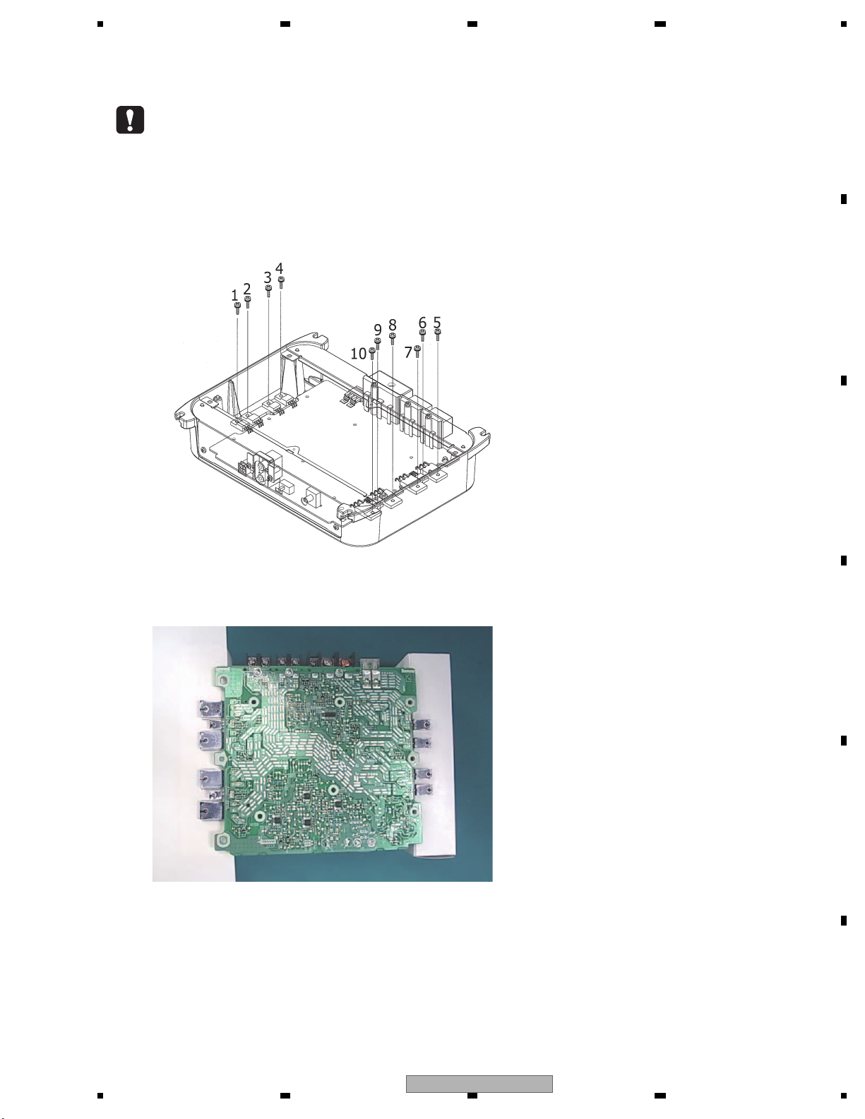
3. When you tighten the screws No. 1 to 10, tightly hold a transistor or a diode to be fixed to prevent the part from
turning by the force of tightening the screw.
(If the part turned, a stress will be applied to the solder and may cause a failure such as a solder crack.)
4. When you replace a part fixed to the heatsink (Q515, Q516, Q517,Q518, Q519, Q520, Q803, Q804, D821 and D822),
adjust the position of the part according to the following.
Put the Amp Unit on blocks.
1. SERVICE PRECAUTIONS
1.1 SERVICE PRECAUTIONS
GM-3400T/XJUC
5
Page 6
1234
1234
C
D
F
A
B
E
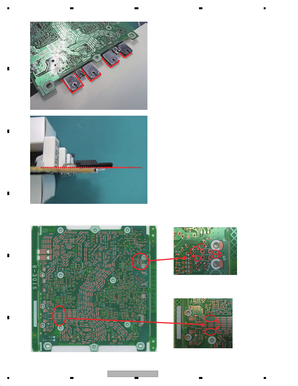
Put a paper between the block and the Amp Unit,
and outline transistors and diodes.
Put a part to replace in the outline.
Align the bottom of a transistor or a diode with the
top of the PC board, and solder it.
Apply grease, GEM1057 to the back of the part.
5. Silk-prints of "L" and "R" on the Amp Unit are printed wrongly each other. ("L" should be "R", and "R" should be "L".)
6
GM-3400T/XJUC
Page 7

5 678
56
7
8
C
D
F
A
B
E
For environmental protection, lead-free solder is used on the printed circuit boards mounted in this unit.
Be sure to use lead-free solder and a soldering iron that can meet specifications for use with lead-free solders for repairs
accompanied by reworking of soldering.
Compared with conventional eutectic solders, lead-free solders have higher melting points, by approximately 40 C.
Therefore, for lead-free soldering, the tip temperature of a soldering iron must be set to around 373 C in general, although
the temperature depends on the heat capacity of the PC board on which reworking is required and the weight of the tip of
the soldering iron.
Compared with eutectic solders, lead-free solders have higher bond strengths but slower wetting times and higher melting
temperatures (hard to melt/easy to harden).
The following lead-free solders are available as service parts:
Parts numbers of lead-free solder:
GYP1006 1.0 in dia.
GYP1007 0.6 in dia.
GYP1008 0.3 in dia.
1.2 NOTES ON SOLDERING
GM-3400T/XJUC
7
Page 8

1234
1234
C
D
F
A
B
E
2. SPECIFICATIONS
Power source...........................14.4 V DC (10.8 V to 15.1 V
allowable)
Grounding system................. Negative type
Current consumption .......... 15 A (at continuous power,
4 ohm)
Average current drawn........ 4 A (4 ohm for two channels)
7.8 A (4 ohm for one channel)
Fuse ......................................... 25 A × 1
Dimensions (W × H × D) ...263 mm × 61 mm × 206
mm(10-3/8 in. × 2-3/8 in. ×
8-1/8 in.)
Weight ..................................... 2 kg (4.4 lbs)
(Leads for wiring not in-
cluded)
Maximum power output ...... 120 W × 2 (4 ohm)
/ 350 W × 1 (4 ohm)
Continuous power output ..60 W × 2 (at 14.4 V, 4 ohm
, 20 Hz to 20 kHz 0.2% THD)
175 W × 1 (at 14.4 V, 4 ohm
, 20 Hz to 20 kHz 0.8% THD)
85 W × 2 (at 14.4 V, 2 ohm
, 20 Hz to 20 kHz 0.8% THD)
Load impedance ................... 4 ohm (2 ohm to 8 ohm allowable)
(Bridge connection: 4 ohm to 8
ohm allowable)
Frequency response............ 10 Hz to 50 kHz (+0 d B,
–1
dB)
Signal-to-noise ratio............ 95 dB (IHF-A network)
Distortion ................................ 0.01 % (10 W, 1 kHz)
Separation .............................. 70 dB (1 kHz)
Low pass filter:
Cut off frequency......... 80 Hz
Cut off slope.................. –12 dB/oct
Gain control:
RCA ................................. 200 mV to 6.5 V
Speaker ........................... 0.8 V to 26 V
Maximum input level / impedance:
RCA .................................. 6.5 V / 22 k ohm
Speaker ............................ 26 V / 9 0 k ohm
CEA2006 Specifications
Power output .......................... 60 W RMS × 2 Channels (at
14.4 V, 4 ohm and
1 % THD
+N)
175 W RMS × 1 Channels
(at 14.4 V, 4 ohm BRIDGE and
1 % THD+N)
85 W RMS × 2 Channels (at
14.4 V, 2 ohm and
1 % THD
+N)
S/N ratio .................................. 75 dBA (reference: 1 W into
4 ohm)
Notes
• Specifications and the design are subject to
modifications without notice due to improvements.
• The average current drawn is nearly the maximum current drawn by this unit when an
audio signal is input. Use this value when
working out total current drawn by multiple
power amplifiers.
Backup current ......................0.1 mA or less
GM-3400T/XJUC
2.1 SPECIFICATIONS
8
GM-3400T/XJUC
Page 9

5 678
56
7
8
C
D
F
A
B
E
GM-3400T/XJEW5, GM-3400T/XJES
Power source..........................14.4 V DC (10.8 V to 15.1 V
allowable)
Grounding system................. Negative type
Current consumption .......... 15 A (at continuous power,
4 ohm)
Average current drawn........ 4 A (4 ohm for two channels)
7.8 A (4 ohm for one channel)
Backup current ....................... 0.1 mA or less
Fuse ......................................... 25 A × 1
Dimensions (W × H × D) ...263 mm × 61 mm × 206
mm
Weight ..................................... 2 kg (Leads forwiring not in-
cluded)
Maximum power output ....... 120 W × 2 (4 ohm)
/ 350 W × 1(4 ohm)
Continuous power output ... 60 W × 2 (at 14.4 V, 4 ohm)
, 20 Hz to 20 kHz 0.2% THD)
175 W × 1 (at 14.4 V, 4 ohm)
, 20 Hz to 20 kHz 0.8% THD)
85 W × 2 (at 14.4 V, 2 ohm)
, 20 Hz to 20 kHz 0.8% THD)
Load impedance ................... 4 ohm (2 ohm to 8 ohm allowable)
(Bridge connection: 4 ohm to 8
ohm allowable)
Frequency response............. 10 Hz to 50 kHz (+0 d B, –1
dB)
Signal-to-noise ratio............ 95 dB (IEC-A network)
Distortion ................................ 0.01 % (10 W, 1 kHz)
Separation ............................. 70 dB (1 kHz)
Low pass filter:
Cut off frequency......... 80 Hz
Cut off slope.................. –12 dB/oct
Gain control:
RCA ................................ 200 mV to 6.5 V
Speaker .......................... 0.8 V to 26 V
Maximum input level / impedance:
RCA ................................ 6.5 V / 22 k ohm
Speaker .......................... 26 V / 9 0 k ohm
Notes
• Specifications and the design are subject to
modifications without notice due to improvements.
• The average current drawn is nearly the maximum current drawn by this unit when an
audio signal is input. Use this value when
working out total current drawn by multiple
power amplifiers.
GM-3400T/XJUC
9
Page 10
1234
1234
C
D
F
A
B
E
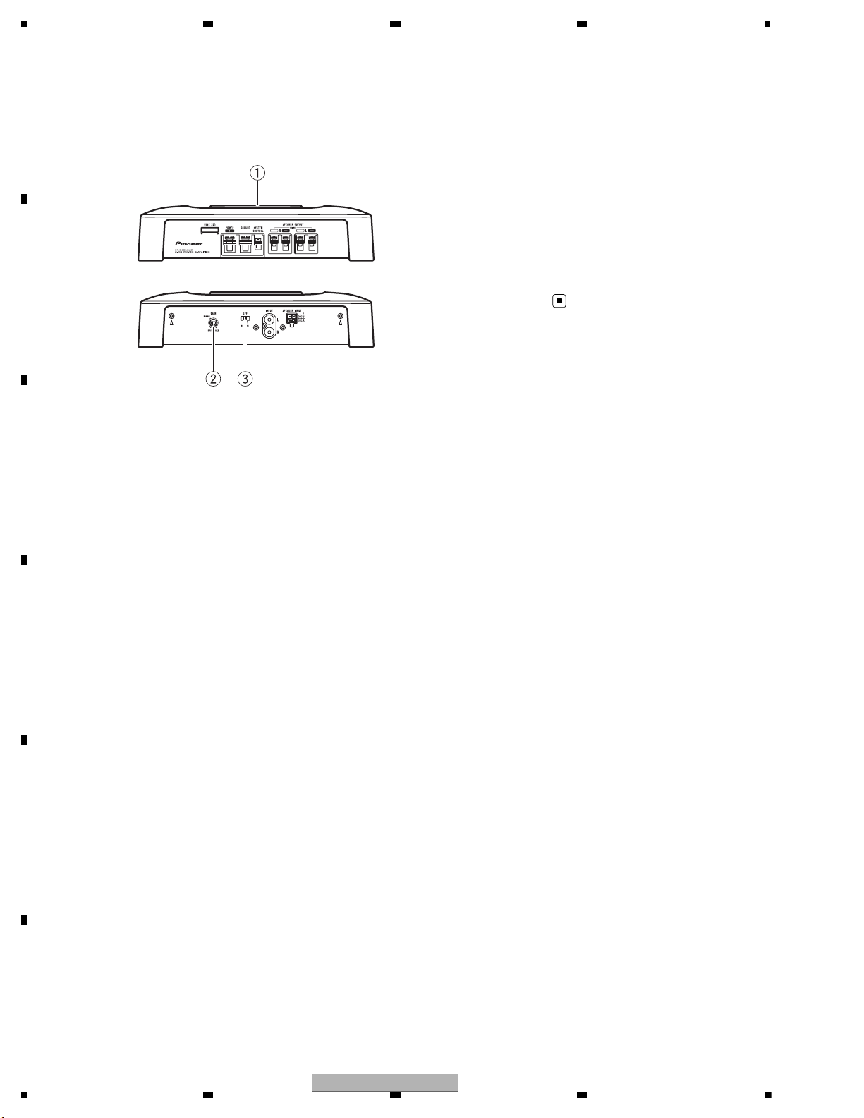
2.2 PANEL FACILITIES
What ’s what
Front side
Rear side
To adjust the switch, use a flathead screwdriver if needed.
1 Power indicator
The power indicator lights up to indicate
power ON.
2 GAIN (gain) control
If output remains low, even when the car
stereo volume is turned up, turn controls to
lower level. If distortion occurs when the car
stereo volume is turned up, turn these controls to higher level.
• For use with an RCA equipped car stereo
(standard output of 500 mV), set to the
NORMAL position. For use with an RCA
equipped Pioneer car stereo, with max.
output of 4 V or more, adjust level to
match that of the car stereo output.
• If you hear too much noise when using
the speaker input terminals, turn the
gain control to higher level.
3 LPF (low-pass filter) switch
Switch the settings based on the connected
speaker.
• When the Subwoofer is connected:
Select ON . This eliminates high range
frequency and outputs low range frequency.
• When the full range speaker is connected:
Select OFF . OFF outputs the entire frequency range.
10
GM-3400T/XJUC
Page 11

5 678
56
7
8
C
D
F
A
B
E
Connection diagram
1 Special red battery wire
RD-223 (sold separately)
After completing all other amplifier connections, finally connect the battery wire terminal
of the amplifier to the positive (
) battery
terminal.
2 Ground wire (Black)
RD-223 (sold separately)
Connect to metal body or chassis.
3 Car stereo with RCA output jacks (sold sepa-
rately)
4 External output
5 Connecting wire with RCA pin plugs (sold se-
parately)
6 Speaker input terminal
7 RCA input jack
8 System remote control wire (sold separately)
Connect male terminal of this wire to the system remote control terminal of the car stereo
(SYSTEM REMOTE CONTROL ). The female
terminal can be connected to the auto-antenna relay control terminal. If the car stereo
lacks a system remote control terminal, connect the male terminal to the power terminal
via the ignition switch.
9 Speaker output terminals
Please see the following section for speaker
connection instructions. Refer to Connections
when using the speaker input wire.
a Fuse (25 A) × 1
b Fuse (30 A) × 2
c Grommet
d Rear side
e Front side
2.3 CONNECTION DIAGRAM
GM-3400T/XJUC
11
Page 12

1234
1234
C
D
F
A
B
E
3. BASIC ITEMS FOR SERVICE
To keep the product quality after servicing, please confirm following check points.
demrifnoc eb ot metIserudecorP.oN
1 Confirm whether the customer complain has
been solved.
The customer complain must not be
reappeared.
Audio and operations must be normal.
2 Check the output sound. Audio and operations must be normal.
retfa ecnaraeppa sti no trid ro sehctarcs oNkcehc ecnaraeppA3
receiving it for service.
See the table below for the items to be checked regarding audio:
Item to be checked regarding audio
Distortion
Noise
Volume too low
Volume too high
Volume fluctuating
Sound interrupted
- Lubricants and Glues List
Name
Grease
Bond
Grease No.
GEM1057
GYL1006
Remarks
Applying to Heatsink
Applying to choke coil, resistor and capacitor
N
G
s
3.1 CHECK POINTS AFTER SERVICING
3.2 JIGS LIST
ame
4. BLOCK DIAGRAM
rease No.
There is not information to be shown in this chapter.
mark
12
GM-3400T/XJUC
Page 13

5 678
56
7
8
C
D
F
A
B
E
5. DIAGNOSIS
5.1 CONNECTOR FUNCTION DESCRIPTION
6. SERVICE MODE
There is not information to be shown in this chapter.
GM-3400T/XJUC
13
Page 14

1234
1234
C
D
F
A
B
E
7. DISASSEMBLY
1
1
2
- Removing the Case (Fig.1)
Remove the four screws
and then remove the Case.
Fig.1
3
1
1
1
1
1
2
2
2
2
2
1
2
2
2
2
2
3
3
3
3
3
3
3
3
Case
- Removing the Amp Unit (Fig.2)
Remove the eight screws
and then remove the Amp Unit.
Remove the two screws.
Amp Unit
Fig.2
Remove the ten screws.
When you tighten the screws indicated
by Arrow 2, tightly hold a transistor or
a diode to be fixed to prevent the part
from turning by the force of tightening
the screw.
(If the part turned, a stress will be
applied to the solder and may cause a
failure such as a solder crack.)
14
GM-3400T/XJUC
Page 15

5 678
56
7
8
C
D
F
A
B
E
Bonding Position
1
GYL1006
1
1
1
1
1
8. EACH SETTING AND ADJUSTMENT
There is not information to be shown in this chapter.
1
1
1
GM-3400T/XJUC
15
Page 16

1234
1234
C
D
F
A
B
E
9. EXPLODED VIEWS AND PARTS LIST
NOTES : Parts marked by " * " are generally unavailable because they are not in our Master Spare Parts List.
The > mark found on some component parts indicates the importance of the safety factor of the part.
Therefore, when replacing, be sure to use parts of identical designation.
Screw adjacent to mark on the product are used for disassembly.
For the applying amount of lubricants or glue, follow the instructions in this manual.
(In the case of no amount instructions,apply as you think it appropriate.)
""
9.1 PACKING
16
GM-3400T/XJUC
Page 17

5 678
56
7
8
C
D
F
A
B
E
(1) PACKING SECTION PARTS LIST
Mark
Mark No. Description Part No.
1 Cushion CZH6698
* 2 Polyethylene Bag CEG1250
* 3 Warranty Card
4 Cord Assy CZD5517
* 5 Polyethylene Bag
6Unit Box
See Contrast table(2)
See Contrast table(2)
See Contrast table(2)
No. Description Part No.
7 Contain Box CZH6703
8 •••••
9 Owner's Manual
10 Screw Assy CEA5330
11 Screw BYC40P180FTB
* 12 Polyethyene Seet CNM4338
See Contrast table(2)
(2) CONTRAST TABLE
GM-3400T/XJUC, GM-3400T/XJEW5 and GM-3400T/XJES are constructed the same except for the following:
Mark No. Description GM-3400T/XJUC GM-3400T/XJEW5 GM-3400T/XJES
* 3 Warranty Card CRY1276 CRY1279 Not used
* 5 Polyethylene Bag CZE2992 CZE2991 CZE2991
6 Unit Box CZH6702 CZH6700
7
9 Owner's Manual CZR5552 CZR5551 CZR5553
Contain Box
CZH6703 CZH6701 CZH6705
CZH6704
Owner's Manual,Installation Manual
Part No. Language
CZR5551 English, Spanish(Espanol), German, French, Italian, Dutch, Russian
CZR5552 English, French, Spanish(Espanol)
CZR5553 English, Spanish(Espanol), Portuguese(B), Arabic
GM-3400T/XJUC
17
Page 18

1234
1234
C
D
F
A
B
E
9.2 EXTERIOR
18
GM-3400T/XJUC
Page 19

5 678
56
7
8
C
D
F
A
B
E
(1) EXTERIOR SECTION PARTS LIST
Mark No. Description Part No.
> 1 Fuse(25 A) CEK1329
2 Screw PBH26P120FTC
3 Screw BBZ30P080FTB
4 Screw BBZ30P080FTC
5 Screw BBZ30P080FTC
Mark No. Description Part No.
9 Panel F (2CH) CZN8458
10 Panel R (2CH) CZN8459
11 Amp Unit
See Contrast table (2)
12 Holder CZN8430
13 Screw PPZ30P100FNN
6 Screw BSZ30P060FTB
7 Screw PPZ30P100FTB
14 Screw PPZ30P100FTB
15 Case Unit
See Contrast table (2)
8 Chassis (Botom) CZN8457
(2) CONTRAST TABLE
GM-3400T/XJUC, GM-3400T/XJEW5 and GM-3400T/XJES are constructed the same except for the following:
Mark No. Description GM-3400T/XJUC GM-3400T/XJEW5 GM-3400T/XJES
11 Amp Unit CZW5581 CZW5581 CZW5582
15 Case Unit CZX6655 CZX6654 CZX6654
GM-3400T/XJUC
19
Page 20

1234
1234
C
D
F
A
B
E
10. SCHEMATIC DIAGRAM
A
A-a
A-a A-b
A-a
A-b
A-b
A-a
Large size
SCH diagram
Guide page
Detailed page
Note: When ordering service parts, be sure to refer to " EXPLODED VIEWS AND PARTS LIST" or
"ELECTRICAL PARTS LIST".
IC301
1
A_OUT2A_-IN3A_+IN4V-
5
B_+IN6B_-IN
8
V+
7
B_OUT
R103
22K
R104
22K
C101
470P
C102
470P
C103
47P
C10747P
C108 47P
C104
47P
R805
4.7K
R806
4.7K
C805
0.0047
C806
0.0047
C822
0.001
C823
0.001
C820
NM
R311
56
R312
C832
NM
C833
NM
C812
0.033
C811
0.033
C821
NM
D110
1SS355
D112
1SS355
D111
1SS355
D109
1SS355
JA101
CKB1068-B
JA103
CKM1463-A
1
L+
2
R+
3
L-
4
R-
R809
1/2W
22
R810
1/2W
22
R820
NM
R821
1/2W
22
R822
1/2W
22
R807
1/2W
120
R808
1/2W
120
R823
1/2W
NM
R824
1/2W
NM
Q803
FKV550N
G
S
D
Q804
FKV550N
G
S
D
C810
3300/16
105
D101
1SS355
D105
1SS355
D103
1SS355
D107
1SS355
D102
1SS355
D106
1SS355
D104
1SS355
D108
1SS355
VR301
10K
TP6
TP7
TP8
TP9
TP10
TP26
TP27
TP28
TP29
TP30
TP31
TP32
TP33
TP34TP35
TP36
TP37
TP38TP39
TP40
TP41
TP42
TP43
TP44
TP45
TP46
TP47
TP48
TP49
TP51
TP50
TP56
TP57
TP58
TP59
TP60TP61
C113
NM
C114
NM
TP52
TP53
TP54
TP55
D821
FML-22S
D822
FML-22R
R812
11K
R813
27K
Q802
KTA1504S
OYG
Q801
KTA1504S
OYG
R827
1/2W10
R828
1/2W10
C824
3300/35
105
C825
3300/35
105
D806
MTZJ16B
D805
MTZJ16B
R825
NM
R826
NM
R711
100
R125
NM
R126
NM
R127
NM
R128
NM
C123
NM
C124
NM
C125
NM
C126
NM
TH7
47
R119
1/4W
470
R120
1/4W
470
R121
51K
1/4W
R122
51K
1/4W
R123
51K
1/4W
R124
51K
1/4W
R803
3.3K
R804
3.3K
E1
E2
C2
Vcc
OPC
Ref
2IN-
2IN+
R101
NM
R829
1/2W
3.3K
R830
1/2W
3.3K
R305
68K
R306
68K
R307
68K
R308
68K
C304
0.022
C303
0.022
C302
0.039
C301
0.039
R831
NM
L802
NM
R113
NM
R114
NM
C119
NM
Q823
KTC3875S
Q824
KTC3875S
R310
2.2K
R309
2.2K
KN802
NM
*L803
BL02RN1R3N1A
*L804
BL02RN1R3N1A
R11110K
0.25%
R10910K
0.25%
R10710K
0.25%
R10510K
0.25%
R112 10K
0.25%
R110 10K
0.25%
R108 10K
0.25%
R106 10K
0.25%
S301
00221461
Q822
KTC9015
ABC
EC
B
Q821
KTC9014
ABCD
EC
B
IC101NJM4565M-D
1
AOUTPUT2A-INPUT3A+INPUT
4
V-
5
B+INPUT
6
B-INPUT
8
V+7BOUTPUT
IC102
1
AOUTPUT2A-INPUT3A+INPUT
4
V-
5
B+INPUT
6
B-INPUT
8
V+7BOUTPUT
C115
10/25
C117
10/25
C118
10/25
C116
10/25
C105
NM
R833
3.9K
R834
3.3K
Q825
KTC9014
ABCD
R832
1/4W
100
R835
0
T801
C831
220/35
C830
220/35
C112
10/25
C111
10/25
R836
1/2W
NM
R837
1/2W
NM
R838
1/2W
NM
R839
1/2W
NM
R313
130K
R314
130K
C827
22/25
C826
22/25
C106 0.0047
C828
47/16
C829
47/16
*JW123
*JW122
*JW124
*JW126
10:5
Lch
Rch
SP LEVEL INPUT
OFF
LPF
OFF
LPF
MI
LPFBUFFER/ISO.AMP
+15V
-15V
+VH
-VH
+VD
-VD
RCA INPUT
LPF OFF
GAIN
MODEL L803 L804 JW122 JW123 JW124 JW126
GM-3400T/XJEW5
GM-3400T/XJUC
GM-3400T/XJES
NJM4565M-D
NJM4558MD
0 dB / 0 dB
0 dB
-31.5 dB ~
VD VH 15 V
1 W +27.8 V +28.0 V +15.1 V
OUTPUT -27.8 V -27.9 V -15.2 V
10.1 AMP UNIT(GUIDE PAGE)
20
GM-3400T/XJUC
Page 21

5 678
56
7
8
C
D
F
A
B
E
A
A-b
R801 15K
R311
56
R312
56
R521
1.1K
R523
4.7K
R525
2.2K
R526
2.2K
R522
1.1K
R524
4.7K
C529
NM
C534
NM
C532
NM
C531
NM
C533
NM
C528
NM
C530
NM
R54147K
D501
MA111
R54247K
D502
MA111
R545
47K
R546
47K
C801 0.001
C709
0.01
R815 47K
R814 1K
C701
NM
C538
0.033
C537
0.033
KN801
CZK2969-A-T
Q522
KTC3911S
GL
Q521
KTC3911S
GL
R544
560K
R543
560K
JA804
CND2458-A
JA805
CND2458-A
C541
3216
NM
C542
3216
NM
C803
3216
NM
Q515
KTC3114A
Q516
KTC3114A
R730
16K
R729
6.8K
R728
12K
VR301
10K
TP1
TP2
TP3
TP4
TP5
TP11
TP12
TP13
TP14
TP15
TP16
TP17
TP18
TP20
TP24
TP26
TP27
TP60TP61
TP66TP67
TP68
TP69
TP70TP71TP72TP73
TP74TP75
TP77
TP78TP79
TP81
TP82
TP83
TP84
TP85
TP86
TP87
TP88
TP89
TP90
TP91
TP92
TP93
TP94
TP95
TP96
TP97
TP19
C5390.001C5400.001
JA801
CKE1055-A
1
+B
2
GND
3
REM
JA501
CKE1057-A
1
L-
2
L+
JA502
CKE1057-A
1
R-
2
R+
Q511
2SA1038S
Q512
2SA1038S
Q514
2SC2389S
Q513
2SC2389S
R701
1/4W
2.2K
R722
100
R714
10K
R713
330K
C702 0.001
R812
11K
R813
27K
R712
22K
R704
4.7K
R705
2.2K
Q703
KN2907AS
D804
1A4-E
D803
1A4-E
C802
0.01
2012
C804
0.22
IC501
1
A_OUT
2
A_-IN3A_+IN
4
V-
5
B_+IN6B_-IN
8
V+7B_OUT
R509
15K
R511
15K
R510
15K
R512
15K
R516
47K
R518
47K
R515
47K
R517
47K
R504
270
R503
270
D706
1SS133
C525
0.001
C526
0.001
R519
1/4W
120
R528
1/4W
120
R527
1/4W
120
R520
1/4W
120
R537
2W
0.1
R539
2W
0.1
R540
2W
0.1
R538
2W
0.1
R547
1/4W
10
R548
1/4W
10
R717
47
Q712
DTA124EKA
C535
NM
C536
NM
R706
NM
R707
NM
R711
100
R709
2.2K
D705
NHSB046AT
R702
7.5K
R716
1K
R715
220
C708
0.01
Q302
2SC2412K
R
Q301
2SC2412K
R
R301
10K
R302
10K
C527
NM
Q517
2SD2439
OP
Q519
2SB1588
OP
Q518
2SD2439
OP
Q520
2SB1588
OP
R720
NM
C704
NM
R723
47K
R724
22K
L801
36uH
K000225700
R726
33K
TH701
470
R507
1/4W
560
R513
1/4W
560
R514
1/4W
560
R508
1/4W
560
D702
1SS133
Q702
2SC2412K
R
Q705
2SC2412K
R
Q710
2SC2412K
R
Q711
2SC2412K
R
Q713
2SC2412K
R
IC801KIA494AF
1
1IN+
2
1IN-
3
FEEDBACK
4
DTC
5
CT
6
RT
7
GND
8C19
E1
10
E2
11
C2
12
Vcc
13
OPC
14
Ref
15
2IN-
16
2IN+
Q709
2SA1037AK
R
R725
330
R727
2.2K
TH702
10K
R703
2.2K
1/4W
R721
1/2W
4.7K
D701
MTZJ7.5B
C711
NM
C513
NM
C515
NM
C514
NM
C516
NM
C508
68P
C507
68P
R505
22K
2012
R506
22K
2012
R310
2.2K
R309
2.2K
C706
0.22
C521
0.22
C524
0.22
C522
0.22
C523
0.22
C543
NM
C544
NM
R733
1/4W
100
R732
2.7K
Q714
2SA1037AKR
S301
C503
100/10
C504
100/10
D707
HZS3A2TD-E
R708
22K
D708
1SS133
D709
1SS133
R802
NM
R734
NM
C707
22/25
C703
100/16
C710
220/6.3
C712
NM
C807 220/6.3
R502
10K
R501
10K
C502
33P
C501
33P
C505
68P
C506
68P
C517
10P
C520
10P
C518
10P
C519
10P
R529
22
3216
R531
22
3216
R532
22
3216
R530
22
3216
R534
47K
R533
47K
R535
47K
R536
47K
R731
6.8K
R710
3.9K
D711
1SS133
D710
1SS133
C512
10P
C511
10P
C510
10P
C509
10P
OFF
LPF
OFF
LPF
MIN MAX
SP OUTPUT
LPF OFF
FUSE (25A)
GAIN
BLUE LED
NJM2068MD
A
AMP UNIT
Symbol indicates a resistor.
No differentiation is made between chip resistors and
discrete resistors.
NOTE :
Symbol indicates a capacitor.
No differentiation is made between chip capacitors and
discrete capacitors.
NM : No Mount
The > mark found on some component parts indicates
the importance of the safety factor of the part.
Therefore, when replacing, be sure to use parts of
identical designation.
>
-31.5 dB ~ -2.2 dB
Silk-prints of "L" and "R" on the Amp Unit
are printed wrongly each other.
("L" should be "R", and "R" should be "L".)
+29 dB
-9.3 dB
GM-3400T/XJUC
21
Page 22

1234
1234
C
D
F
A
B
E
A-a A-b
A-b
R311
56
R312
56
R521
1.1K
R523
4.7K
R525
2.2K
R526
2.2K
R522
1.1K
R524
4.7K
C529
NM
C534
NM
C532
NM
C531
NM
C533
NM
C528
NM
C530
NM
R54147K
D501
MA111
R54247K
D502
MA111
R545
47K
R546
47K
C538
0.033
C537
0.033
Q522
KTC3911S
GL
Q521
KTC3911S
GL
R544
560K
R543
560K
C541
3216
NM
C542
3216
NM
Q515
KTC3114A
Q516
KTC3114A
TP66TP67
TP68
TP69
TP70TP71TP72TP73
TP74TP75
TP77
TP78TP79
TP81
TP82
TP83
TP84
TP85
TP86
TP87
TP88
TP89
TP90
TP91
TP92
TP93
TP94
TP95
TP96
TP97
C5390.001C5400.001
JA501
CKE1057-A
1
L-2L+
JA502
CKE1057-A
1
R-2R+
Q511
2SA1038S
Q512
2SA1038S
Q514
2SC2389S
Q513
2SC2389S
IC501
1
A_OUT
2
A_-IN
3
A_+IN
4
V-
5
B_+IN
6
B_-IN
8
V+
7
B_OUT
R509
15K
R511
15K
R510
15K
R512
15K
R516
47K
R518
47K
R515
47K
R517
47K
R504
270
R503
270
C525
0.001
C526
0.001
R519
1/4W
120
R528
1/4W
120
R527
1/4W
120
R520
1/4W
120
R537
2W
0.1
R539
2W
0.1
R540
2W
0.1
R538
2W
0.1
R547
1/4W
10
R548
1/4W
10
Q712
DTA124EKA
C535
NM
C536
NM
R706
NM
R707
NM
Q302
2SC2412K
R
Q301
2SC2412K
R
R301
10K
R302
10K
C527
NM
Q517
2SD2439
OP
Q519
2SB1588
OP
Q518
2SD2439
OP
Q520
2SB1588
OP
R507
1/4W
560
R513
1/4W
560
R514
1/4W
560
R508
1/4W
560
C513
NM
C515
NM
C514
NM
C516
NM
C508
68P
C507
68P
R505
22K
2012
R506
22K
2012
C521
0.22
C524
0.22
C522
0.22
C523
0.22
C543
NM
C544
NM
C503
100/10
C504
100/10
D708
1SS133
D709
1SS133
R734
NM
C712
NM
R502
10K
R501
10K
C502
33P
C501
33P
C505
68P
C506
68P
C517
10P
C520
10P
C518
10P
C519
10P
R529223216
R531223216
R532223216
R530223216
R534
47K
R533
47K
R535
47K
R536
47K
C512
10P
C511
10P
C510
10P
C509
10P
MIN MAX
SP OUTPUT
NJM2068MD
A
AMP UNIT
Silk-prints of "L" and "R" on the Amp Unit
are printed wrongly each other.
("L" should be "R", and "R" should be "L".)
+29 dB
-9.3 dB
22
GM-3400T/XJUC
Page 23

5 678
56
7
8
C
D
F
A
B
E
A-a A-b
A-b
R801 15KNMC801 0.001
C709
0.01
R815 47K
R814 1K
C701
NM
KN801
CZK2969-A-T
JA804
CND2458-A
JA805
CND2458-A
C803
3216
NM
R730
16K
R729
6.8K
R728
12K
TP1
TP2
TP3
TP4
TP5
TP11
TP12
TP13
TP14
TP15
TP16
TP17
TP18
TP20
TP24
TP19
JA801
CKE1055-A
1+B2
GND3REM
R701
1/4W
2.2K
R722
100
R714
10K
R713
330K
C702 0.001
R712
22K
R704
4.7K
R705
2.2K
Q703
KN2907AS
D804
1A4-E
D803
1A4-E
C802
0.01
2012
C804
0.22
D706
1SS133
R52
1/4W
120
R717
47
R709
2.2K
D705
NHSB046AT
R702
7.5K
R7161KR715
220
C708
0.01
R720
NM
C704
NM
R723
47K
R724
22K
L801
36uH
K000225700
R726
33K
TH701
470
R50
1/4W
560
D702
1SS133
Q702
2SC2412K
R
Q705
2SC2412K
R
Q710
2SC2412K
R
Q711
2SC2412K
R
Q713
2SC2412K
R
IC801KIA494AF
1
1IN+21IN-3FEEDBACK
4
DTC5CT6RT7GND8C1
9
E110E211C2
12
Vcc13OPC14Ref152IN-162IN+
Q709
2SA1037AK
R
R725
330
R727
2.2K
TH702
10K
R703
2.2K
1/4W
R721
1/2W
4.7K
D701
MTZJ7.5B
C711
NM
C706
0.22
C52
0.22
R733
1/4W
100
R732
2.7K
Q714
2SA1037AKR
D707
HZS3A2TD-E
R708
22K
D708
1SS133
D709
1SS133
R802
NM
R734
NM
C707
22/25
C703
100/16
C710
220/6.3
C712
NM
C807 220/6.3
R731
6.8K
R710
3.9K
D711
1SS133
D710
1SS133
FUSE (25A)
BLUE LED
Symbol indicates a resistor.
No differentiation is made between chip resistors and
discrete resistors.
NOTE :
Symbol indicates a capacitor.
No differentiation is made between chip capacitors and
discrete capacitors.
NM : No Mount
The > mark found on some component parts indicates
the importance of the safety factor of the part.
Therefore, when replacing, be sure to use parts of
identical designation.
>
GM-3400T/XJUC
23
Page 24

1234
1234
C
D
F
A
B
E
A-bA-a
A-a
A-b
IC301
1
A_OUT
2
A_-IN
3
A_+IN
4
V-
5
B_+IN
6
B_-IN
8
V+
7
B_OUT
R103
22K
R104
22K
C101
470P
C102
470P
C103
47P
C10747P
C108 47P
C104
47P
R311
56
R312
56
C812
0.033
C811
0.033
D110
1SS355
D112
1SS355
D111
1SS355
D109
1SS355
JA101
CKB1068-B
JA103
CKM1463-A
1
L+2R+3L-4R-
D101
1SS355
D105
1SS355
D103
1SS355
D107
1SS355
D102
1SS355
D106
1SS355
D104
1SS355
D108
1SS355
VR301
10K
TP36
TP37
TP38
TP40
TP41
TP42
TP43
TP44
TP45
TP46
TP47
TP48
TP49
TP51
TP50
TP56
TP57
TP58
TP59
TP60TP61
C113
NM
C114
NM
TP52
TP53
TP54
TP55
R827
Q712
DTA124EKA
R706
NM
R707
NM
R125
NM
R126
NM
R127
NM
R128
NM
R
1
R
1
C123
NM
C124
NM
C125
NM
C126
NM
R119
1/4W
470
R120
1/4W
470
R121
51K
1/4W
R122
51K
1/4W
R123
51K
1/4W
R124
51K
1/4W
R101
NM
R305
68K
R306
68K
R307
68K
R308
68K
C304
0.022
C303
0.022
C302
0.039
C301
0.039
R831
NM
L802
NM
R113
NM
R114
NM
C119
NM
R310
2.2K
R309
2.2K
KN802
NM
R11110K
0.25%
R10910K
0.25%
R10710K
0.25%
R10510K
0.25%
R112 10K
0.25%
R110 10K
0.25%
R108 10K
0.25%
R106 10K
0.25%
S301
00221461
IC101NJM4565M-D
1
AOUTPUT
2
A-INPUT
3
A+INPUT
4
V-
5
B+INPUT
6
B-INPUT
8
V+
7
BOUTPUT
IC102
1
AOUTPUT
2
A-INPUT
3
A+INPUT
4
V-
5
B+INPUT
6
B-INPUT
8
V+
7
BOUTPUT
C115
10/25
C117
10/25
C118
10/25
C116
10/25
C105
NM
D708
1SS133
D709
C112
10/25
C111
10/25
R313
130K
R314
130K
C106 0.0047
Lch
Rch
SP LEVEL INPUT
OFF
LPF
OFF
LPF
MIN MAX
LPFBUFFER/ISO.AMP
+15V
+VD
RCA INPUT
LPF OFF
GAIN
NJM4565M-D
NJM4558MD
0 dB / 0 dB
0 dB
-31.5 dB ~ -2.2 dB
VD VH 15 V
1 W +27.8 V +28.0 V +15.1 V
OUTPUT -27.8 V -27.9 V -15.2 V
-9.3 d
24
GM-3400T/XJUC
Page 25

5 678
56
7
8
C
D
F
A
B
E
A-a
A-b
A-bA-a
R805
4.7K
R806
4.7K
C805
0.0047
C806
0.0047
C822
0.001
C823
0.001
C820
NM
R815 47K
C832NMC833
NM
C821
NM
R809
1/2W
22
R810
1/2W
22
R820
NM
R821
1/2W
22
R822
1/2W
22
R807
1/2W
120
R808
1/2W
120
R823
1/2W
NM
R824
1/2W
NM
Q803
FKV550N
G
S
D
Q804
FKV550N
G
S
D
C810
3300/16
105
TP6
TP7
TP8
TP9
TP10
TP26
TP27
TP28
TP29
TP30
TP31
TP32
TP33
TP34TP35
TP38TP39
D821
FML-22S
D822
FML-22R
R812
11K
R813
27K
Q802
KTA1504S
OYG
Q801
KTA1504S
OYG
R827
1/2W10
R828
1/2W10
C824
3300/35
105
C825
3300/35
105
D806
MTZJ16B
D805
MTZJ16B
R825
NM
R826
NM
R711
100
R709
2.2K
TH701
470
R803
3.3K
R804
3.3K
IC801KIA494AF
1
1IN+21IN-3FEEDBACK
4
DTC5CT6RT7GND8C1
9
E110E211C2
12
Vcc13OPC14Ref152IN-162IN+
R829
1/2W
3.3K
R830
1/2W
3.3K
Q823
KTC3875S
Q824
KTC3875S
Q714
2SA1037AKR
*L803
BL02RN1R3N1A
*L804
BL02RN1R3N1A
Q822
KTC9015
ABC
EC
B
Q821
KTC9014
ABCD
EC
B
R708
22K
D708
1SS133
D709
R833
3.9K
R834
3.3K
Q825
KTC9014
ABCD
R832
1/4W
100
R835
0
T801
C831
220/35
C830
220/35
C807 220/6.3
R836
1/2W
NM
R837
1/2W
NM
R838
1/2W
NM
R839
1/2W
NM
C827
22/25
C826
22/25
C828
47/16
C829
47/16
R710
*JW123
*JW122
*JW124
*JW126
10:5
+15V
-15V
+VH
-VH
+VD
-VD
MODEL L803 L804 JW122 JW123 JW124 JW126
GM-3400T/XJEW5
GM-3400T/XJUC
GM-3400T/XJES
GM-3400T/XJUC
25
Page 26

1234
1234
C
D
F
A
B
E
11. PCB CONNECTION DIAGRAM
A
A
AMP UNIT
Capacitor
Connector
P.C.Board
Chip Part
SIDE B
SIDE A
NOTE FOR PCB DIAGRAMS
1.The parts mounted on this PCB
include all necessary parts for
several destination.
For further information for
respective destinations, be sure
to check with the schematic dia gram.
2.Viewpoint of PCB diagrams
FRONT
11.1 AMP UNIT
26
GM-3400T/XJUC
Page 27

5 678
56
7
8
C
D
F
A
B
E
A
SIDE A
GM-3400T/XJUC
27
Page 28

1234
1234
C
D
F
A
B
E
A
A
AMP UNIT
28
GM-3400T/XJUC
Page 29

5 678
56
7
8
C
D
F
A
B
E
A
SIDE B
Silk-prints of "L" and "R" on the Amp Unit
are printed wrongly each other.
("L" should be "R", and "R" should be "L".)
GM-3400T/XJUC
29
Page 30

1234
1234
C
D
F
A
B
E
12. ELECTRICAL PARTS LIST
NOTE:
Parts whose parts numbers are omitted are subject to being not supplied.
The part numbers shown below indicate chip components.
Chip Resistor
RS1/_S___J,RS1/__S___J
Chip Capacitor (except for CQS.....)
CKS....., CCS....., CSZS.....
The > mark found on some component parts indicates the importance of the safety factor of the part.
Therefore, when replacing, be sure to use parts of identical designation.
Meaning of the figures and others in the parentheses in the parts list.
Example) IC 301 is on the point (face A, 91 of x-axis, and 111 of y-axis) of the corresponding
PC board.
IC 301 (A, 91, 111) IC NJM2068V
Circuit Symbol and No. Part No.
Unit Number : CZW5581(UC,EW5)
Unit Number : CZW5582(ES)
Unit Name : Amp Unit
A
Unit Number : CZW5581(UC,EW5)
Unit Number : CZW5582(ES)
Unit Name : Amp Unit
MISCELLANEOUS
IC 101 IC NJM4565MD
IC 102 IC NJM4565MD
IC 301 IC NJM4558MD
IC 501 IC NJM2068MD
IC 801 IC KIA494AF
Q 301 Transistor 2SC2412K
Q 302 Transistor 2SC2412K
Q 511 Transistor 2SA1038S
Q 512 Transistor 2SA1038S
Q 513 Transistor 2SC2389S
Q 514 Transistor 2SC2389S
Q 515 Transistor KTC3114
Q 516 Transistor KTC3114
Q 517 Transistor 2SD2439
Q 518 Transistor 2SD2439
Q 519 Transistor 2SB1588
Q 520 Transistor 2SB1588
Q 521 Transistor KTC3911S
Q 522 Transistor KTC3911S
Q 702 Transistor 2SC2412K
Q 703 Transistor KN2907AS
Q 705 Transistor 2SC2412K
Q 709 Transistor 2SA1037K
Q 710 Transistor 2SC2412K
Q 711 Transistor 2SC2412K
Q 712 Chip Digital Transistor DTA124EKA
Q 713 Transistor 2SC2412K
Circuit Symbol and No. Part No.
Q 714 Transistor 2SA1037K
Q 801 Transistor KTA1504S
Q 802 Transistor KTA1504S
Q 803 Transistor FKV550N
Q 804 Transistor FKV550N
Q 821 Transistor KTC9014
Q 822 Transistor KTC9015
Q 823 Transistor KTC3875S
Q 824 Transistor KTC3875S
Q 825 Transistor KTC9014
D 101 Diode 1SS355
D 102 Diode 1SS355
D 103 Diode 1SS355
D 104 Diode 1SS355
D 105 Diode 1SS355
D 106 Diode 1SS355
D 107 Diode 1SS355
D 108 Diode 1SS355
D 109 Diode 1SS355
D 110 Diode 1SS355
D 111 Diode 1SS355
D 112 Diode 1SS355
D 501 Diode 1SS355
D 502 Diode 1SS355
D 701 Diode MTZJ7R5(B)
D 702 Diode 1SS133
D 705 Chip LED NHSB046AT
D 706 Diode 1SS133
D 707 Diode HZS3L(A2)
D 708 Diode 1SS133
D 709 Diode 1SS133
D 803 Diode 1A4-E
D 804 Diode 1A4-E
D 805 Diode MTZJ16(B)
D 806 Diode MTZJ16(B)
D 821 Diode FML22S
D 822 Diode FML22R
L 801 Choke Coil 36 uH CZT2944
L 803 Coil(ES) CZT2945
L 804 Coil(ES) CZT2945
T 801 Transformer CZT2946
30
GM-3400T/XJUC
Page 31

5 678
56
7
8
C
D
F
A
B
E
Circuit Symbol and No. Part No.
TH701 Posistor CZC2982
TH702 Thermistor CZC2994
Circuit Symbol and No. Part No.
R 518 RS1/16S473J
R 519 120 ohm CZC2986
R 520 120 ohm CZC2986
S 301 Switch(LPF-OFF) CZS2928
VR301 Variable Resistor 10 kohm CZC2975
JA101 Pin Jack CKB1068
JA103 Socket CKM1463
JA501 Terminal CKE1057
R 521 RS1/16S112J
R 522 RS1/16S112J
R 523 RS1/16S472J
R 524 RS1/16S472J
R 525 RS1/16S222J
JA502 Terminal CKE1057
JA801 Terminal CKE1055
R 526 RS1/16S222J
R 527 120 ohm CZC2986
JA804 Terminal CND2458
JA805 Terminal CND2458
KN801 Terminal CZK2969
R 528 120 ohm CZC2986
R 529 RS1/8S220J
R 530 RS1/8S220J
RESISTORS
R 531 RS1/8S220J
R 532 RS1/8S220J
R 103 RS1/16S223J
R 104 RS1/16S223J
R 105 10 kohm CCN1152
R 106 10 kohm CCN1152
R 107 10 kohm CCN1152
R 533 RS1/16S473J
R 534 RS1/16S473J
R 535 RS1/16S473J
R 536 RS1/16S473J
R 537 0.1 ohm CZC2974
R 108 10 kohm CCN1152
R 109 10 kohm CCN1152
R 110 10 kohm CCN1152
R 111 10 kohm CCN1152
R 112 10 kohm CCN1152
R 538 0.1 ohm CZC2974
R 539 0.1 ohm CZC2974
R 540 0.1 ohm CZC2974
R 541 RS1/16S473J
R 542 RS1/16S473J
R 119 470 ohm CZC2987
R 120 470 ohm CZC2987
R 121 51 kohm CZC2988
R 122 51 kohm CZC2988
R 123 51 kohm CZC2988
R 543 RS1/16S564J
R 544 RS1/16S564J
R 545 RS1/16S473J
R 546 RS1/16S473J
R 547 10 ohm CZC2984
R 124 51 kohm CZC2988
R 301 RS1/16S103J
R 302 RS1/16S103J
R 305 RS1/16S683J
R 306 RS1/16S683J
R 548 10 ohm CZC2984
R 701 2.2 kohm CZC2980
R 702 RS1/16S752J
R 703 2.2 kohm CZC2980
R 704 RS1/16S472J
R 307 RS1/16S683J
R 308 RS1/16S683J
R 309 RS1/16S222J
R 310 RS1/16S222J
R 311 RS1/16S560J
R 705 RS1/16S222J
R 708 RS1/16S223J
R 709 RS1/16S222J
R 710 RS1/16S392J
R 711 RS1/16S101J
R 312 RS1/16S560J
R 313 RS1/16S134J
R 314 RS1/16S134J
R 501 RS1/16S103J
R 502 RS1/16S103J
R 712 RS1/16S223J
R 713 RS1/16S334J
R 714 RS1/16S103J
R 715 RS1/16S221J
R 716 RS1/16S102J
R 503 RS1/16S271J
R 504 RS1/16S271J
R 505 RS1/10S223J
R 506 RS1/10S223J
R 507 560 ohm CZC2981
R 717 RS1/16S470J
R 721 RD1/2PM472J
R 722 RS1/16S101J
R 723 RS1/16S473J
R 724 RS1/16S223J
R 508 560 ohm CZC2981
R 509 RS1/16S153J
R 510 RS1/16S153J
R 511 RS1/16S153J
R 512 RS1/16S153J
R 725 RS1/16S331J
R 726 RS1/16S333J
R 727 RS1/16S222J
R 728 RS1/16S123J
R 729 RS1/16S682J
R 513 560 ohm CZC2981
R 514 560 ohm CZC2981
R 515 RS1/16S473J
R 516 RS1/16S473J
R 517 RS1/16S473J
R 730 RS1/16S163J
R 731 RS1/16S682J
R 732 RS1/16S272J
R 733 100 ohm CZC2985
R 801 RS1/16S153J
GM-3400T/XJUC
31
Page 32

1234
1234
C
D
F
A
B
E
Circuit Symbol and No. Part No.
R 803 RS1/16S332J
R 804 RS1/16S332J
R 805 RS1/16S472J
R 806 RS1/16S472J
R 807 RD1/2PM121J
R 808 RD1/2PM121J
R 809 RD1/2PM220J
R 810 RD1/2PM220J
R 812 RS1/16S113J
R 813 RS1/16S273J
Circuit Symbol and No. Part No.
C 537 CKSRYB333K50
C 538 CKSRYB333K50
C 539 CQMA102J50
C 540 CQMA102J50
C 702 CKSRYB102K50
C 703 100 uF/16 V CZC2991
C 706 CKSRYB224K16
C 707 22 uF/25 V CZC2989
C 708 CKSRYB103K50
C 709 CKSRYB103K50
R 814 RS1/16S102J
R 815 RS1/16S473J
R 821 RD1/2PM220J
R 822 RD1/2PM220J
R 827 RD1/2PM100J
R 828 RD1/2PM100J
R 829 RD1/2PM332J
R 830 RD1/2PM332J
R 832 100 ohm CZC2985
R 833 RS1/16S392J
R 834 RS1/16S332J
R 835 RS1/16S0R0J
CAPACITORS
C 101 CCSRCH471J50
C 102 CCSRCH471J50
C 103 CCSRCH470J50
C 104 CCSRCH470J50
C 106 CQMA472J50
C 107 CCSRCH470J50
C 108 CCSRCH470J50
C 111 CEAT100M50
C 112 CEAT100M50
C 115 CEAT100M50
C 710 220 uF/6.3 V CZC2992
C 801 CCSRCH102J50
C 802 CKSQYB103K50
C 804 CFTLA224J50
C 805 CKSRYB472K50
C 806 CKSRYB472K50
C 807 220 uF/6.3 V CZC2992
C 810 3 300 uF/16 V CZC2977
C 811 CKSRYB333K50
C 812 CKSRYB333K50
C 822 CCSRCH102J50
C 823 CCSRCH102J50
C 824 3 300 uF/35 V CZC2978
C 825 3 300 uF/35 V CZC2978
C 826 22 uF/25 V CZC2989
C 827 22 uF/25 V CZC2989
C 828 47 uF/16 V CZC2990
C 829 47 uF/16 V CZC2990
C 830 220 uF/35 V CZC2993
C 831 220 uF/35 V CZC2993
C 116 CEAT100M50
C 117 CEAT100M50
C 118 CEAT100M50
C 301 CFTLA393J50
C 302 CFTLA393J50
C 303 CKSRYB223K50
C 304 CKSRYB223K50
C 501 CCSRCH330J50
C 502 CCSRCH330J50
C 503 CEAT101M10
C 504 CEAT101M10
C 505 CCSRCH680J50
C 506 CCSRCH680J50
C 507 CCSRCH680J50
C 508 CCSRCH680J50
C 517 CCSRCH100D50
C 518 CCSRCH100D50
C 519 CCSRCH100D50
C 520 CCSRCH100D50
C 521 CKSRYB224K16
C 522 CKSRYB224K16
C 523 CKSRYB224K16
C 524 CKSRYB224K16
C 525 CKSRYB102K50
C 526 CKSRYB102K50
32
GM-3400T/XJUC
 Loading...