

PIONEER GEX-P7000TV Service Manual
PIONEER ELECTRONIC CORPORATION 4-1, Meguro 1-Chome, Meguro-ku, Tokyo 153-8654, Japan
PIONEER ELECTRONICS SERVICE INC. P.O.Box 1760, Long Beach, CA 90801-1760 U.S.A.
PIONEER ELECTRONIC [EUROPE] N.V. Haven 1087 Keetberglaan 1, 9120 Melsele, Belgium
PIONEER ELECTRONICS ASIACENTRE PTE.LTD. 253 Alexandra Road, #04-01, Singapore 159936
C PIONEER ELECTRONIC CORPORATION 1999
K-ZZS. APR.1999 Printed in Japan
ORDER NO.
CRT2385
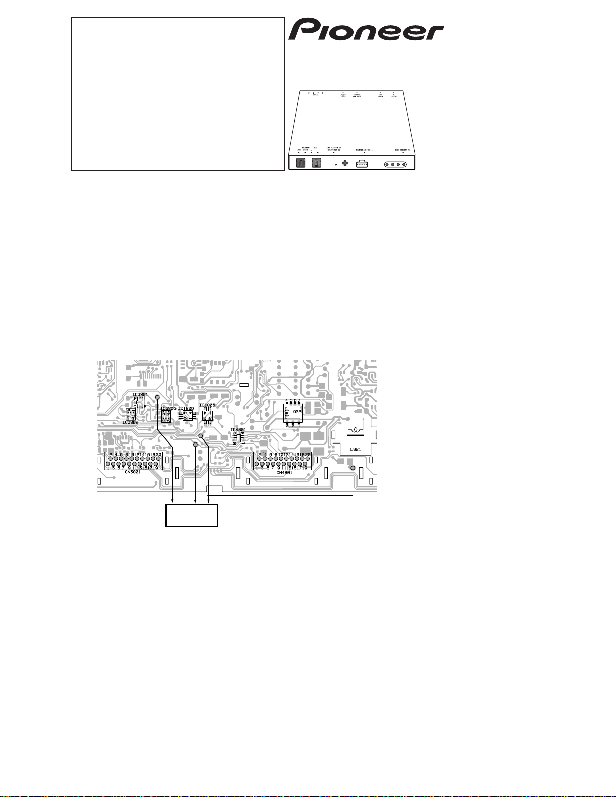
HIDE-AWAY TV TUNER
GEX-P7000TV UC,ES
GEX-P7000TVP/EW
CONTENTS
1. SAFETY INFORMATION ............................................2
2. EXPLODED VIEWS AND PARTS LIST.......................2
3. BLOCK DIAGRAM AND SCHEMATIC DIAGRAM .....6
4. PCB CONNECTION DIAGRAM ................................23
5. ELECTRICAL PARTS LIST ........................................28
6. ADJUSTMENT..........................................................46
7. GENERAL INFORMATION .......................................49
7.1 IC ........................................................................49
7.2 CIRCUIT DESCRIPTION......................................58
8. OPERATIONS AND SPECIFICATIONS.....................60
GEX-P7000TVP EW,ES
- This product is a hide-away tuner, and cannot operate by itself. When operating this unit for servicing, switch to the
FM modulator mode with the slide switch located on the bottom plate.
- To receive the remote control data , connect the remote sensor , as shown below:
GND
DSEN
REM
5V
Remote
sensor
2
GEX-P7000TV,P7000TVP
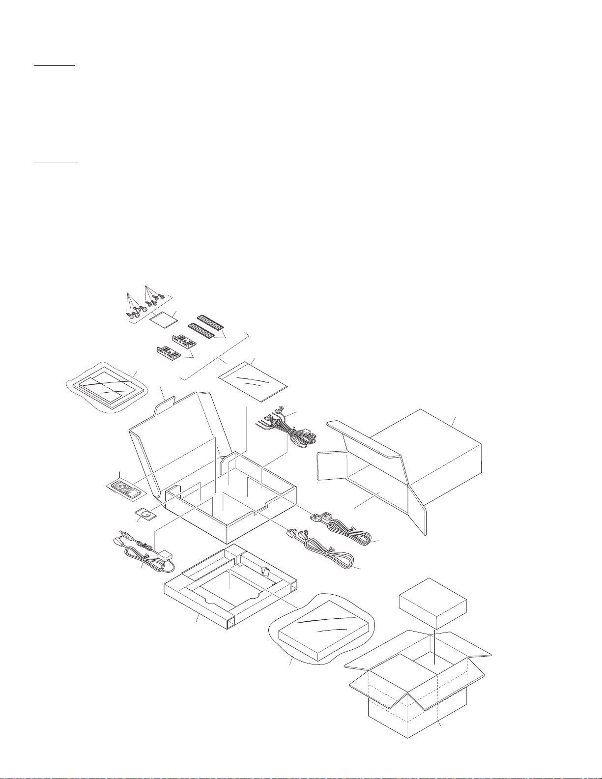
2. EXPLODED VIEWS AND PARTS LIST
2.1 PACKING
15
13
14
16
11
10
2
4
3
5
12
1
7
18
17
9
8
6
1. SAFETY INFORMATION(GEX-P7000TV/UC)
CAUTION
This service manual is intended for qualified service technicians; it is not meant for the casual do-it-yourselfer.
Qualified technicians have the necessary test equipment and tools, and have been trained to properly and safely repair
complex products such as those covered by this manual.
Improperly performed repairs can adversely affect the safety and reliability of the product and may void the warranty.
If you are not qualified to perform the repair of this product properly and safely; you should not risk trying to do so
and refer the repair to a qualified service technician.
W
ARNING
This product contains lead in solder and certain electrical parts contain chemicals which are known to the state of
California to cause cancer, birth defects or other reproductive harm.
Health & Safety Code Section 25249.6 - Proposition 65
3
GEX-P7000TV,P7000TVP
* 1-1 Card See Contrast table(2)
1-2 Owner’s Manual See Contrast table(2)
1-3 Installation Manual See Contrast table(2)
1-4 Polyethylene Bag See Contrast table(2)
1-5 Warranty Card See Contrast table(2)
1-6 Owner’s Manual See Contrast table(2)
2 Cord Assy CDE6094
3 Cord Assy CDE5880
4 Cord Assy CDE5906
5 Antenna Select Unit CWM5606
6 Screw BNC40P120FZK
7 Polyethylene Bag CEG1158
8 Screw HMF40P080FZK
* 9 Polyethylene Bag CEG1101
10 Remote Control Unit CXB4141
11 Polyethylene Bag
See Contrast table(2)
12 Battery CEX1030
13 Carton
See Contrast table(2)
14 Sub Carton CHG3796
15 Contain Box
See Contrast table(2)
16 Protector CHP2158
17 Angle(x2) CNB2351
18 Fastener(x2) CNM3728
Mark No. Description Part No. Mark No. Description Part No.
(1) PACKING SECTION PARTS LIST
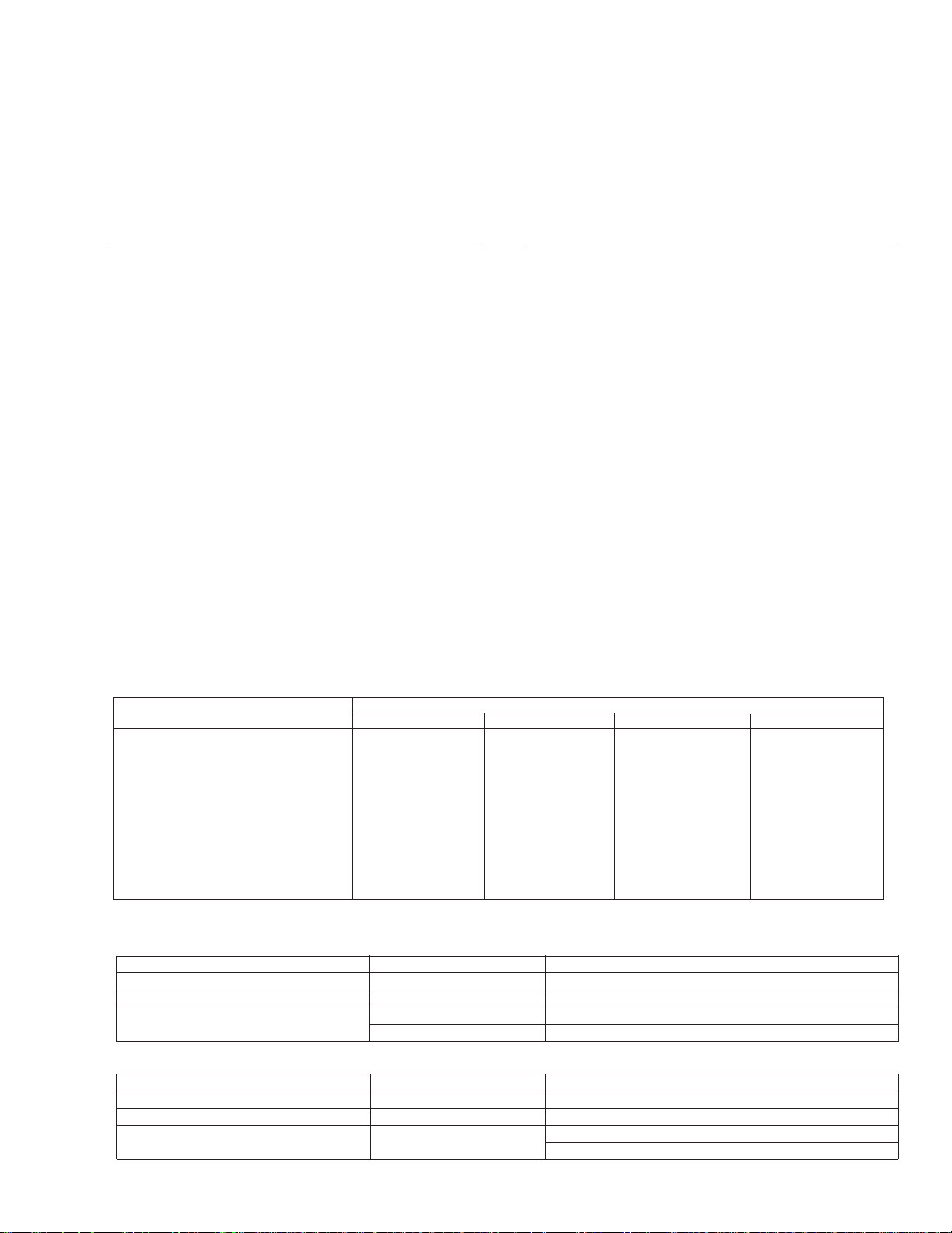
NOTE:
- Parts marked by “*” are generally unavailable because they are not in our Master Spare Parts List.
- Screws adjacent to ∇ mark on the product are used for disassembly.
- Owner’s Manual
Model Part No. Language
GEX-P7000TV/UC CRD3021 English, French
GEX-P7000TV/ES,P7000TVP/ES CRD3048, CRD3046 English, Spanish
GEX-P7000TVP/EW CRD3023 English, Spanish, German
CRD3024 French, Italian, Dutch
- Installation Manual
Model Part No. Language
GEX-P7000TV/UC CRD3022 English, French
GEX-P7000TV/ES,P7000TVP/ES CRD3049, CRD3047 English, Spanish
GEX-P7000TVP/EW CRD3026 English, Spanish, German,
French, Italian, Dutch
Part No.
Mark No. Symbol and Description GEX-P7000TV/UC GEX-P7000TV/ES GEX-P7000TVP/EW GEX-P7000TVP/ES
* 1-1 Card ARY1048 Not used Not used Not used
1-2 Owner’s Manual CRD3021 CRD3048 CRD3023 CRD3046
1-3 Installation Manual CRD3022 CRD3049 CRD3026 CRD3047
1-4 Polyethylene Bag CEG1116 Not used CEG1116 Not used
1-5 Warranty Card Not used Not used CRY1087 Not used
1-6 Owner’s Manual Not used Not used CRD3024 Not used
11 Polyethylene Bag CEG1173 CEG-162 CEG-162 CEG-162
13 Carton CHG3794 CHG3795 CHG3793 CHG3792
15 Contain Box CHL3794 CHL3795 CHL3793 CHL3792
(2) CONTRAST TABLE
GEX-P7000TV/UC, GEX-P7000TV/ES, GEX-P7000TVP/EW and GEX-P7000TVP/ES are constructed the
same except for the following:
4
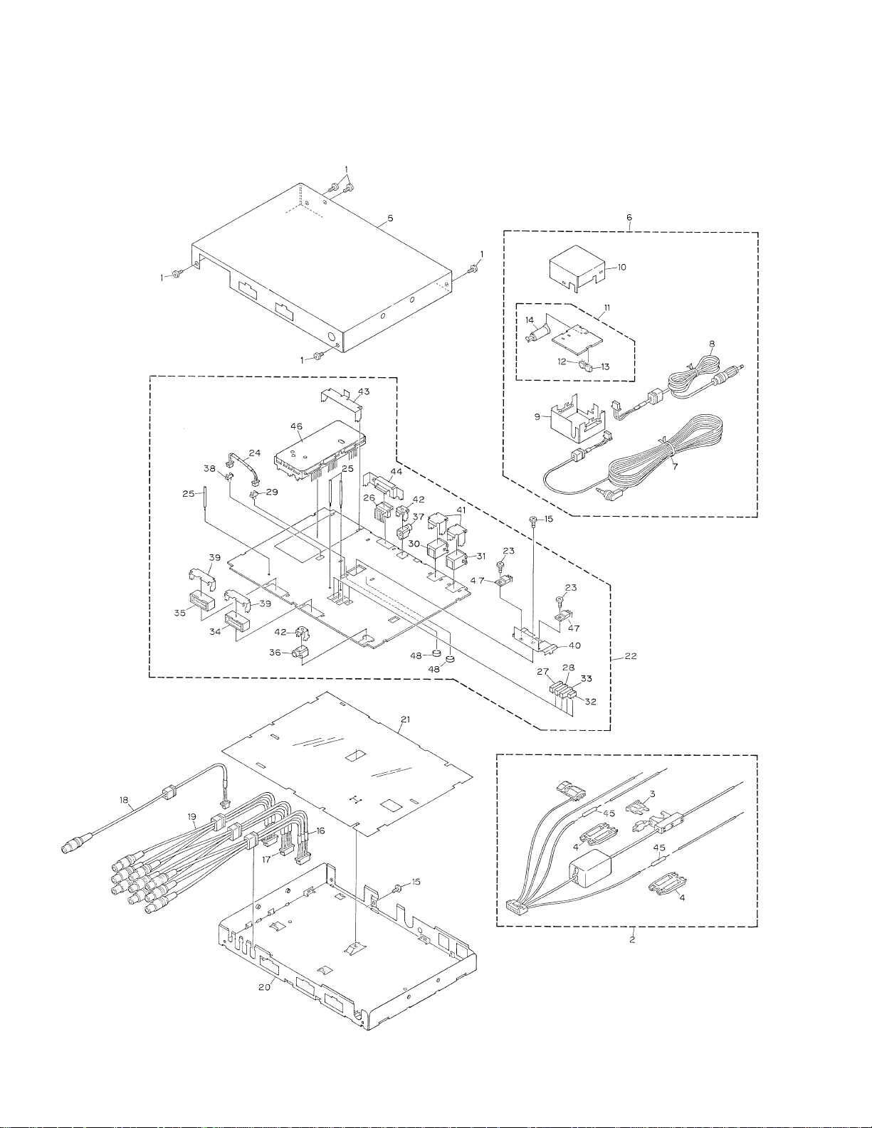
GEX-P7000TV,P7000TVP
2.2 EXTERIOR
5
GEX-P7000TV,P7000TVP
1 Screw BSZ30P060FZK
2 Cord Assy CDE6094
3 Fuse(4A) CEK1001
4 Cap CNS1472
5 Case
See Contrast table(2)
6 Antenna Select Assy CWM5606
7 Cord CDE5482
8 Antenna Cable CDH1207
9 Chassis CNA1555
10 Case CNB1764
11 Antenna Select Unit CWX2200
12 Plug(CN502) CKS1222
13 Plug(CN501) CKS2812
14 Antenna Jack(CN503) CKX1006
15 Screw BSZ30P060FMC
16 Cord Assy CDE5872
17 Cord Assy CDE5873
18 Cord CDE5878
19 Cord Assy CDE5879
20 Chassis CNA2151
21 Insulator CNM6162
22 TV Modulator Unit
See Contrast table(2)
23 Screw BMZ26P060FUC
24 Cord
See Contrast table(2)
25 Clamper CEF1008
26 Plug(CN901) CKS-462
27 Plug(CN802) CKS-570
28 Plug(CN803) CKS2717
29 Connector(CN1001)
See Contrast table(2)
30 Connector(CN651) CKS3409
31 Connector(CN652) CKS3414
32 Connector(CN801) CKS3582
33 Connector(CN804) CKS3586
34 Connector(CN4801) CKS3644
35 Connector(CN3801) CKS3645
36 Jack(CN501) CKS3727
37 Connector(CN721) CKS4124
38 Connector(CN1002)
See Contrast table(2)
39 Holder CNC7047
40 Holder CNC7634
41 Holder CNC7838
42 Holder CNC8205
43 Holder CNC8207
44 Holder CNC8208
45 Resistor RS1/2P102JL
46 TV Front End
See Contrast table(2)
47 Transistor(Q930,935) 2SD2396
48 Spacer CNM6437
(1) EXTERIOR SECTION PARTS LIST
Mark No. Description Part No. Mark No. Description Part No.
Part No.
Mark No. Symbol and Description GEX-P7000TV/UC GEX-P7000TV/ES GEX-P7000TVP/EW GEX-P7000TVP/ES
5 Case CNB2439 CNB2439 CNB2437 CNB2437
22 TV Modulator Unit CWM6345 CWM6510 CWM6346 CWM6511
24 Cord CDE6010 CDE6010 Not used Not used
29 Connector(CN1001) CKS3124 CKS3124 Not used Not used
38 Connector(CN1002) CKS4198 CKS4198 Not used Not used
46 TV Front End CWB1085 CWB1085 CWB1086 CWB1086
(2) CONTRAST TABLE
GEX-P7000TV/UC, GEX-P7000TV/ES, GEX-P7000TVP/EW and GEX-P7000TVP/ES are constructed the
same except for the following:
6
GEX-P7000TV,P7000TVP
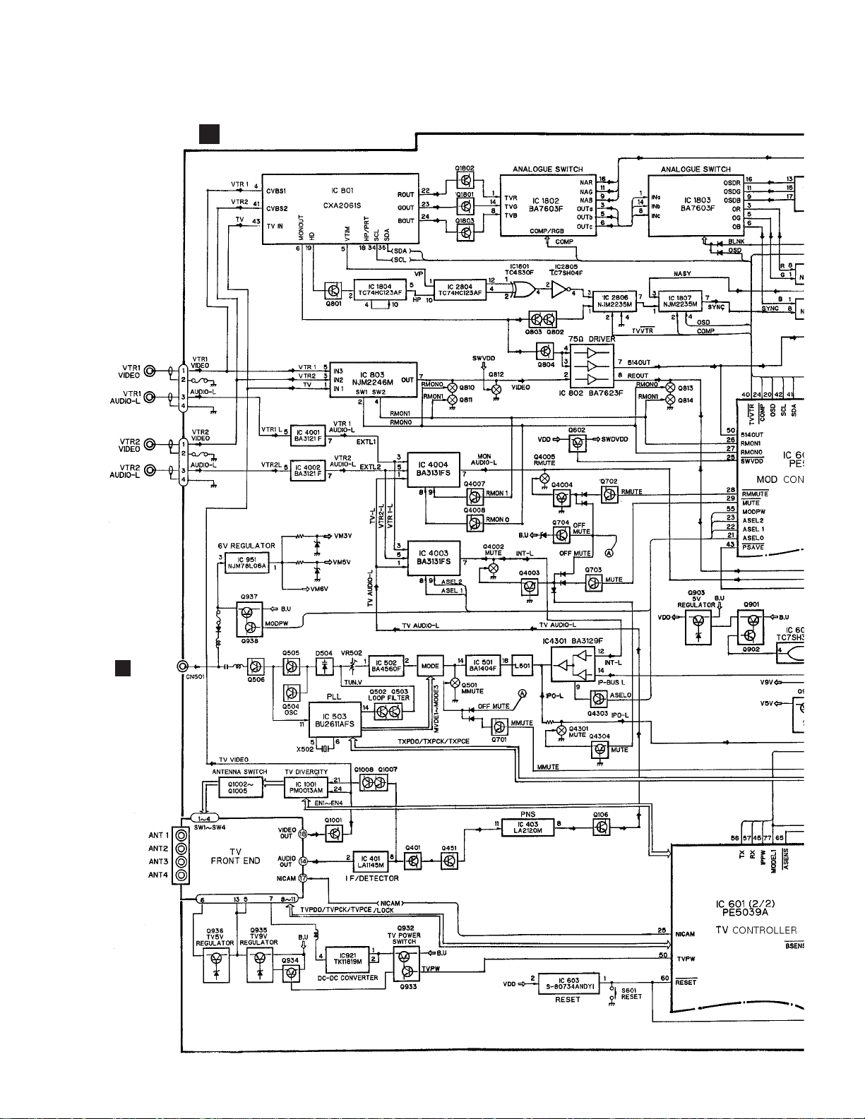
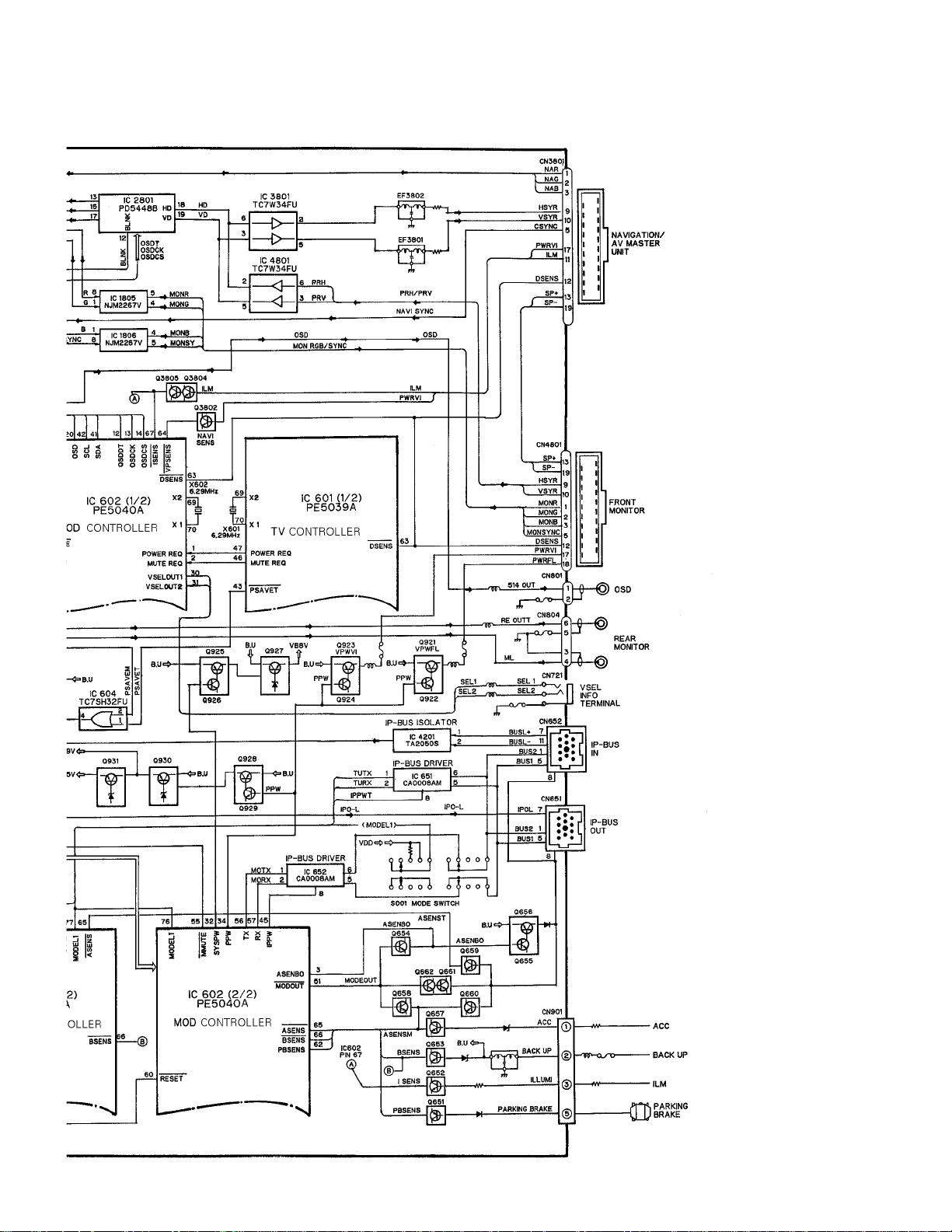
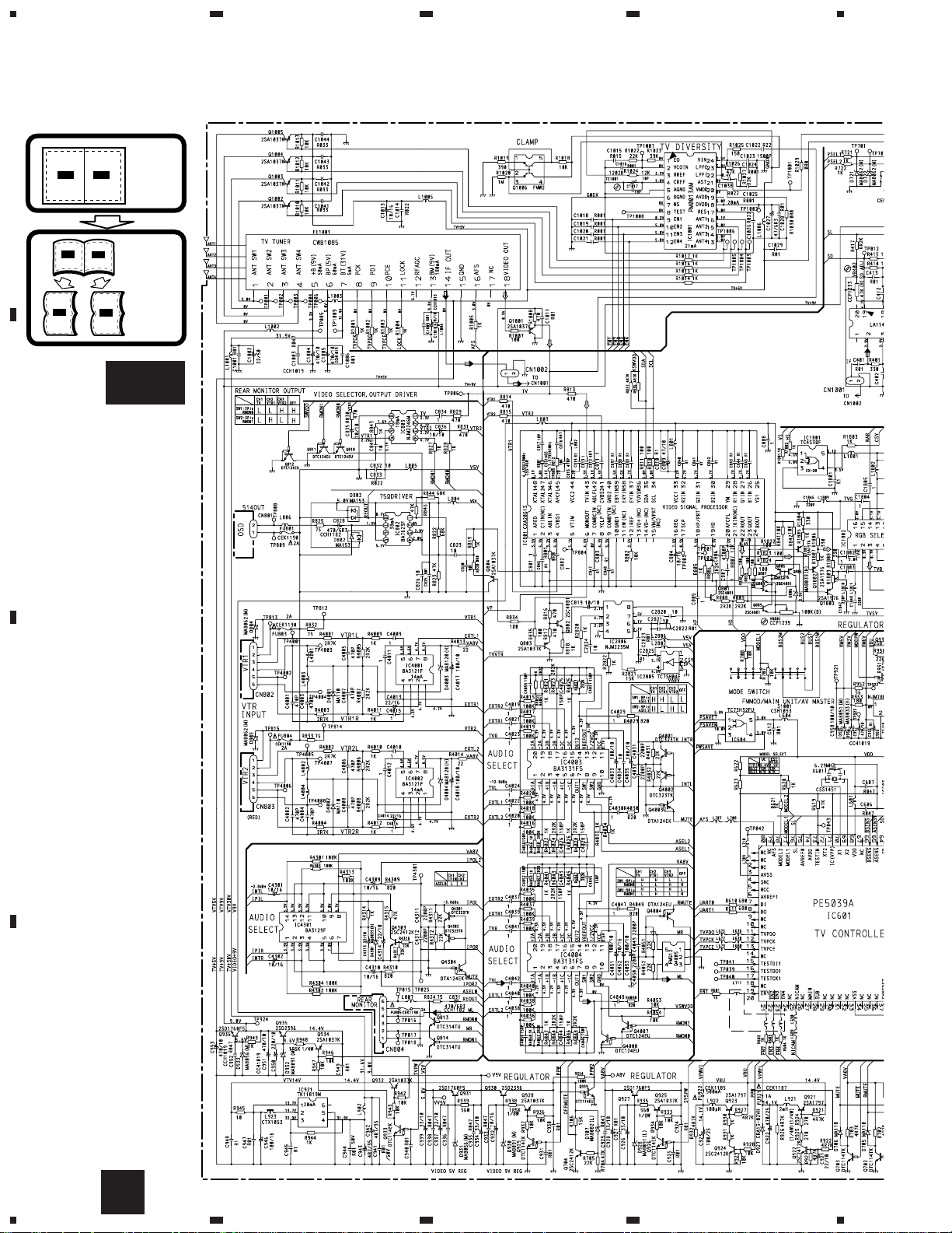
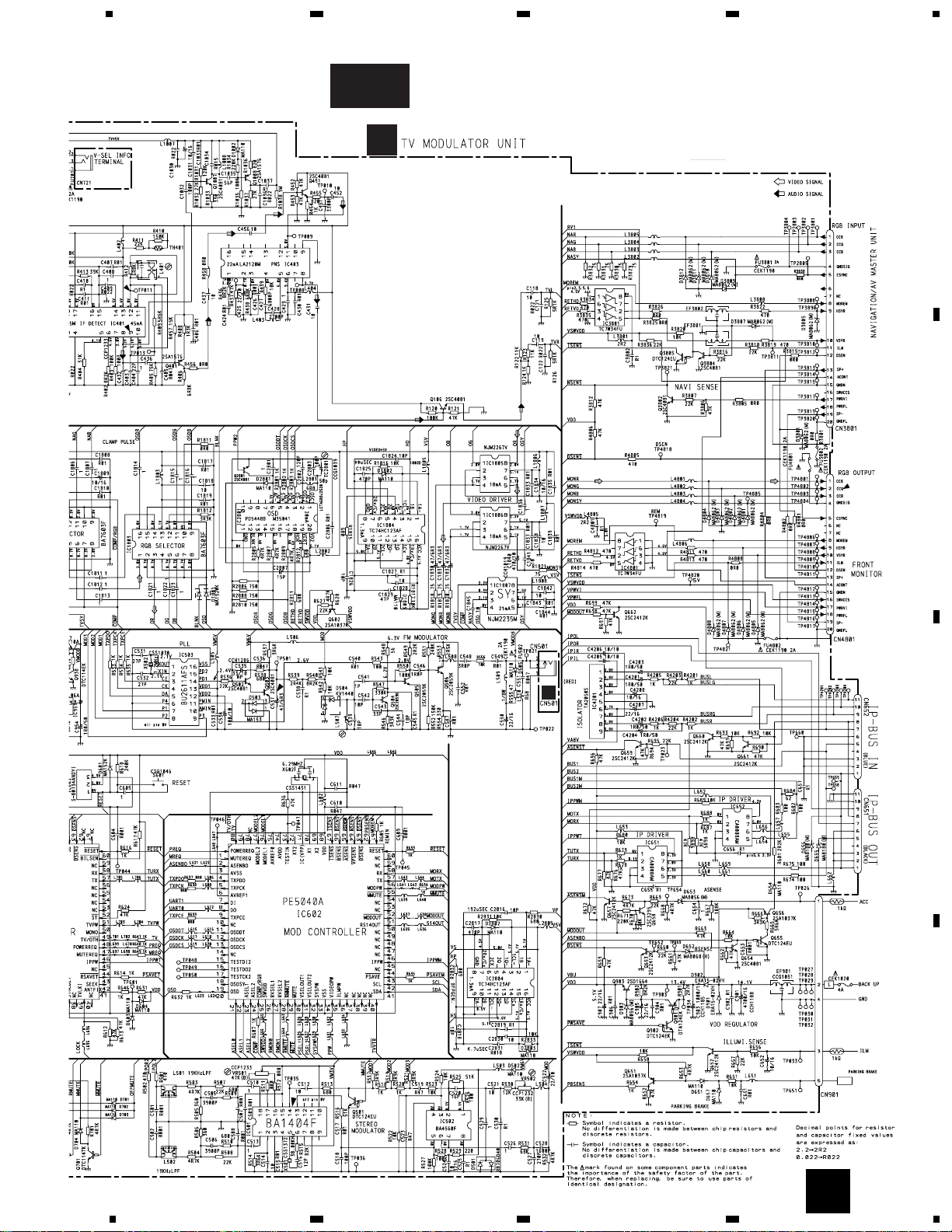
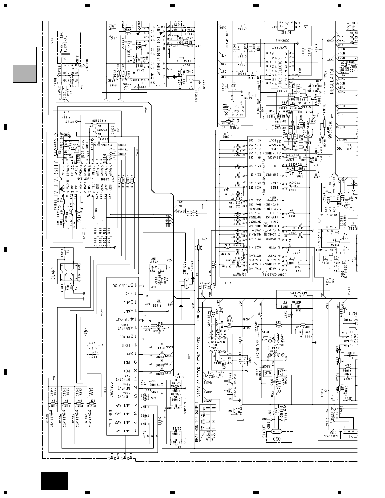
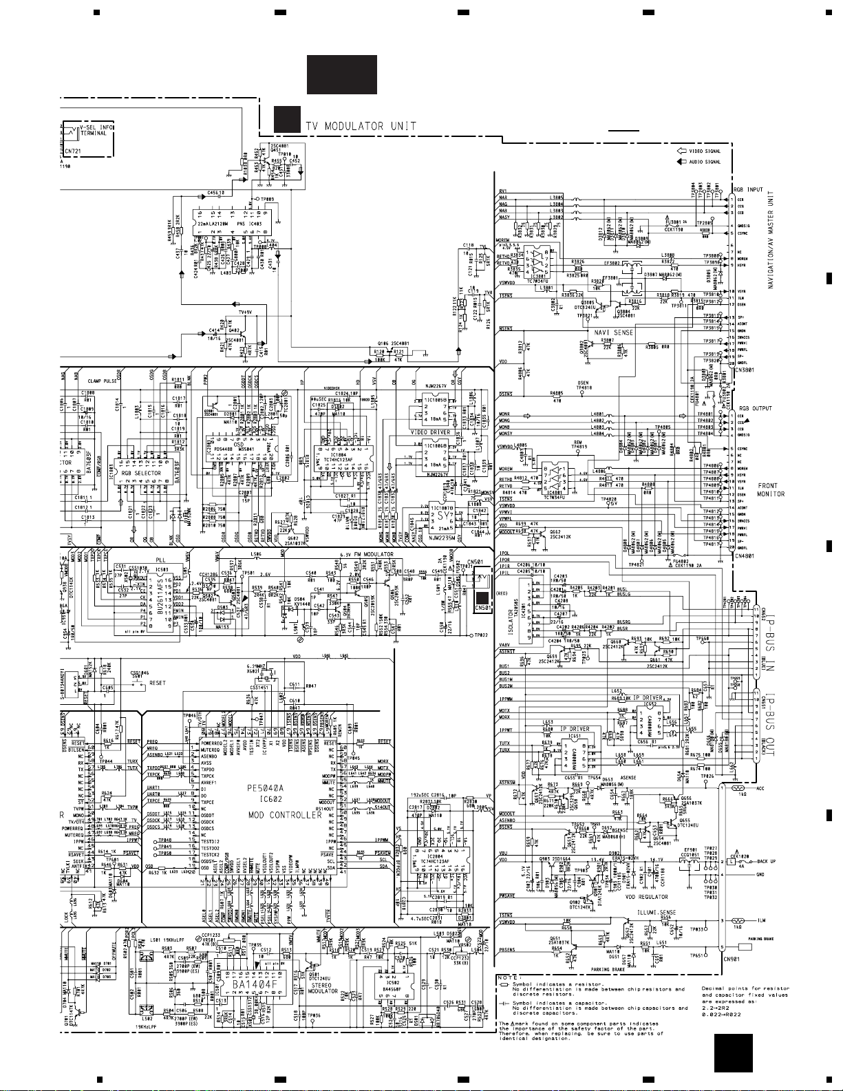
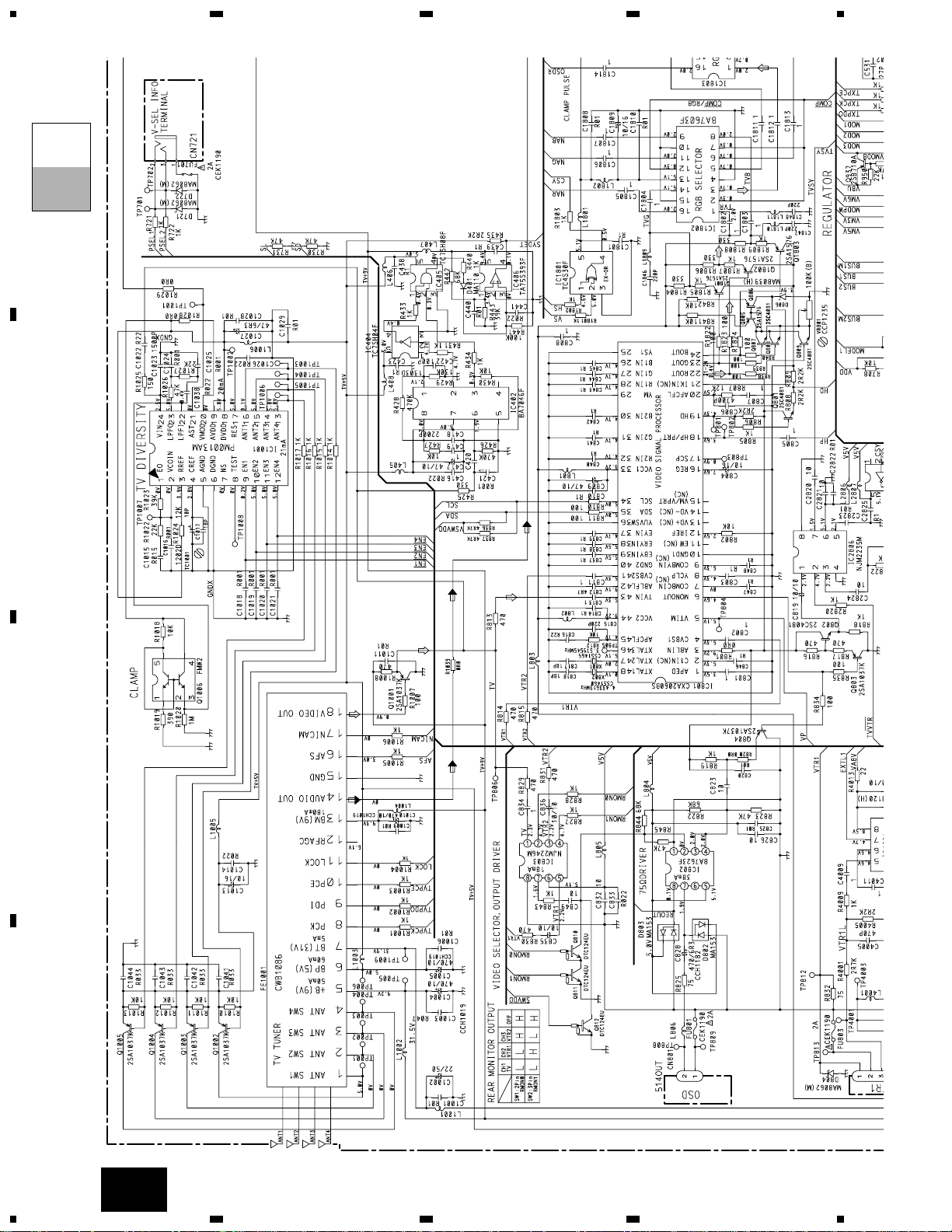
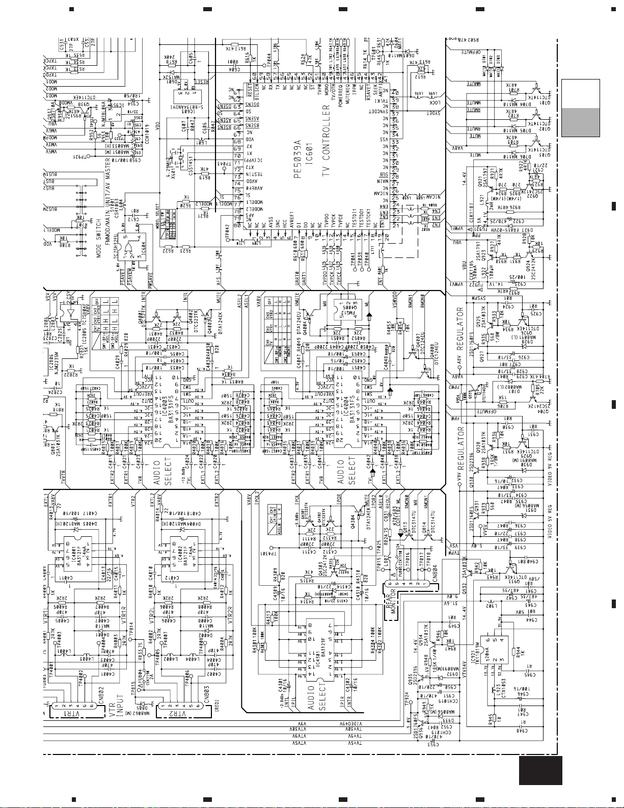
3. BLOCK DIAGRAM AND SCHEMATIC DIAGRAM
3.1 BLOCK DIAGRAM(GEX-P7000TV)
B
CN501
A
TV MODULATOR UNIT
7
GEX-P7000TV,P7000TVP
8
GEX-P7000TV,P7000TVP
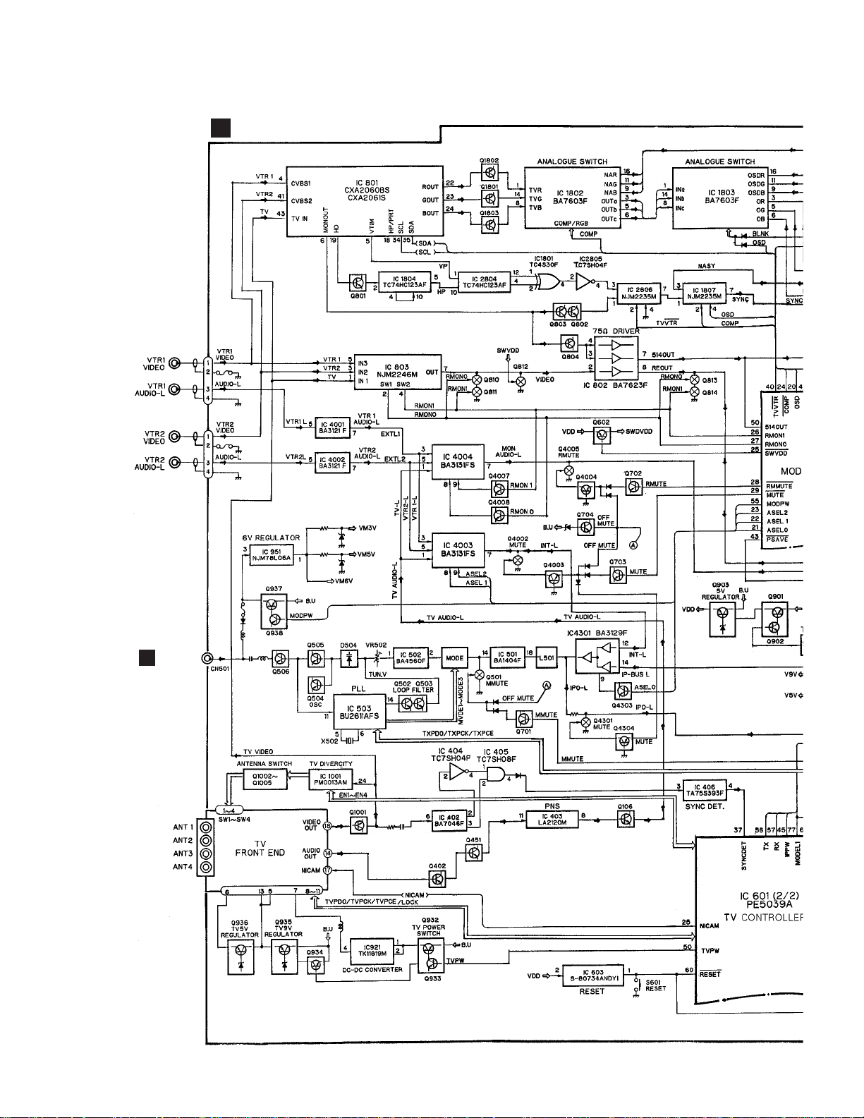
3.2 BLOCK DIAGRAM(GEX-P7000TVP)
B
CN501
A
TV MODULATOR UNIT
9
GEX-P7000TV,P7000TVP
10
GEX-P7000TV,P7000TVP
1
23
4
1234
D
C
B
A
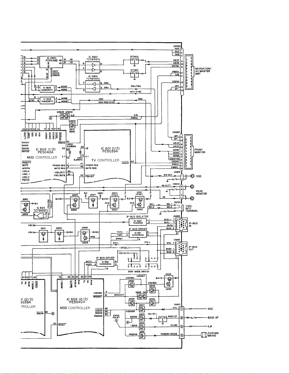
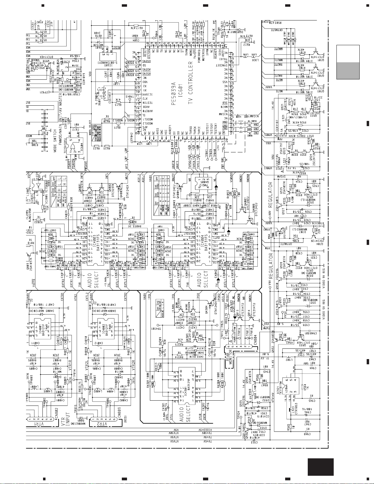
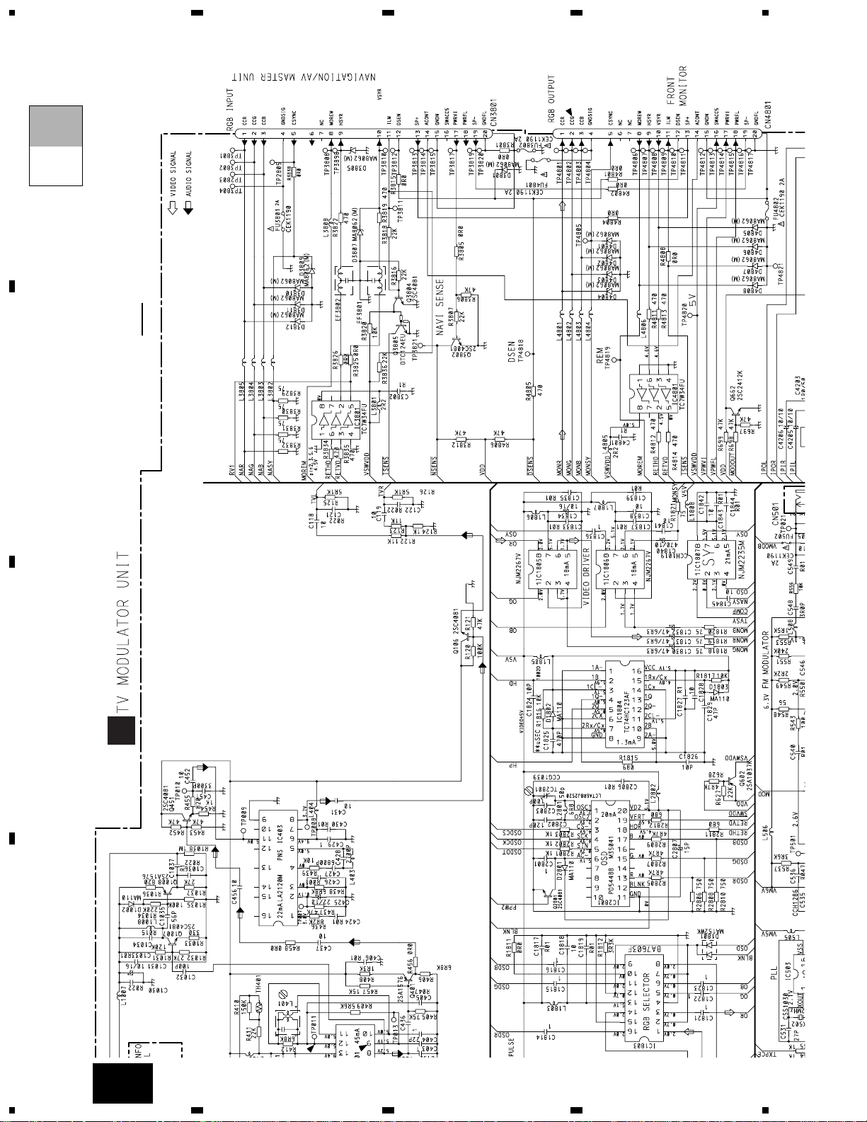
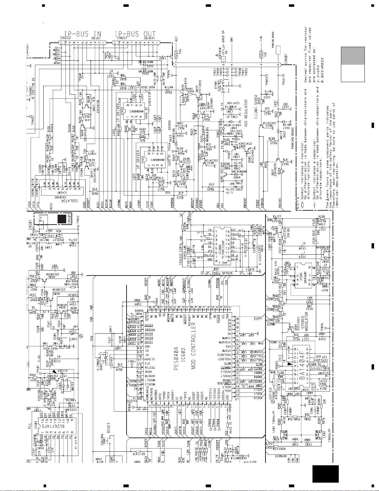
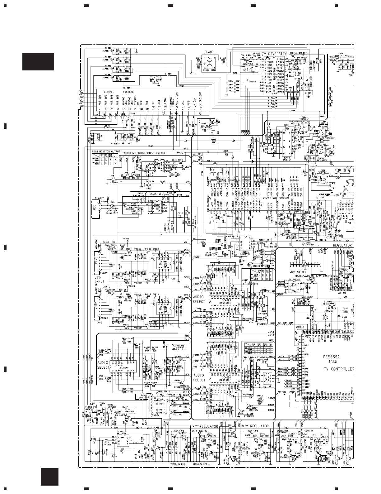
3.3 OVERALL CONNECTION DIAGRAM(GUIDE PAGE)(GEX-P7000TV)
Note: When ordering service parts, be sure to refer to “EXPLODED VIEWS AND PARTS LIST” or “ELECTRICAL
PARTS LIST”.
A
A-aA-a A-b A-b
A-aA-a
A-b A-b
A-b A-b
A-a A-a
Large size
SCH diagram
Guide page
Detailed page
A-a
11
GEX-P7000TV,P7000TVP
5
6
78
5
6
7
8
D
C
B
A
A
B
A
GND
SWITCH:
S1001:MODE SWITCH......FMMOD-MAIN UNIT-AV MASTER
The underlined indicates the switch position.
A-b
12
GEX-P7000TV,P7000TVP
1
23
4
1234
D
C
B
A
A-a
A-a
A-b
13
GEX-P7000TV,P7000TVP
5
6
78
5
6
78
D
C
B
A
A-a
A-a
A-b
14
GEX-P7000TV,P7000TVP
1
23
4
1234
D
C
B
A
A-b
A
GND
SWITCH:
S1001:MODE SWITCH......FMMOD-MAIN UNIT-AV MASTER
The underlined indicates the switch position.
A-a
A-b
15
GEX-P7000TV,P7000TVP
5
6
78
5
6
78
D
C
B
A
A-b
B
GND
A-a
A-b
16
GEX-P7000TV,P7000TVP
1
23
4
1234
D
C
B
A
3.4 OVERALL CONNECTION DIAGRAM(GUIDE PAGE)(GEX-P7000TVP)
A-a
A
17
GEX-P7000TV,P7000TVP
5
6
78
5
6
78
D
C
B
A
A-b
A
B
GND
SWITCH:
S1001:MODE SWITCH......FMMOD-MAIN UNIT-AV MASTER
The underlined indicates the switch position.
A
18
GEX-P7000TV,P7000TVP
1
23
4
1234
D
C
B
A
A-a
A-a
A-b
19
GEX-P7000TV,P7000TVP
5
6
78
5
6
78
D
C
B
A
A-a
A-a
A-b
 Loading...