

Page 1

FH-P80BT
English Español Deutsch Français Italiano Nederlands
MANUEL D’INSTALLATION
INSTALLATION MANUAL
Pycckий
Page 2
Contents Connecting the units
Connecting the units ............................ 2
Power cable connection .................................. 4
Connecting to separately sold power amp ...............
Installation ............................................. 8
Before installing this unit ............................... 8
Installation with the holder
and side bracket ........................................ 8
Installation using the screw holes
on the side of the unit ............................... 9
Installing the microphone ............................. 10
When installing the microphone
on the sun visor .........................................10
When installing the microphone
on the steering column ........................... 10
Adjusting the microphone angle .................. 11
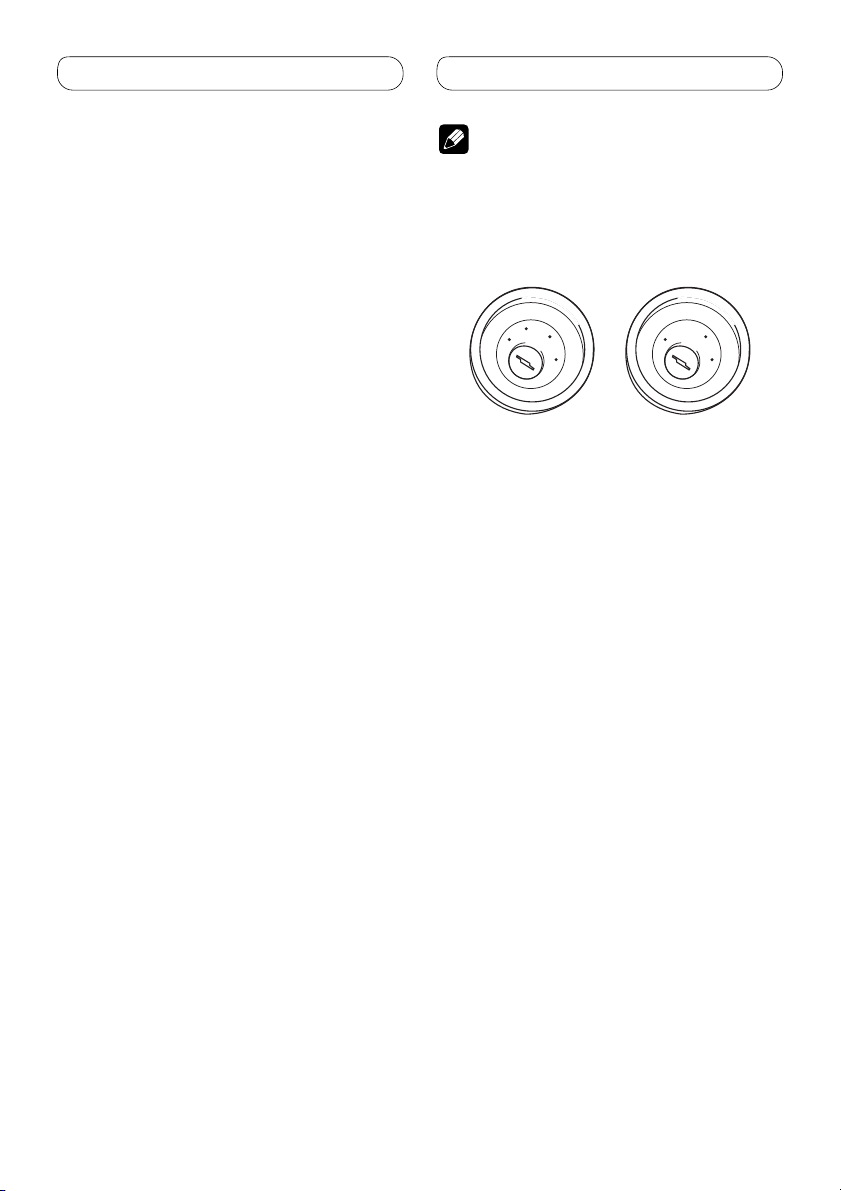
Note
• When this unit is installed in a vehicle without
6
ACC (accessory) position on the ignition switch,
red cable must be wired to the terminal that can
detect the operation of the ignition key. Otherwise,
battery drain may result.
C
C
A
O
F
N
F
O
ACC position
S
T
A
R
T
No ACC position
• Use this unit in other than the following
conditions could result in fire or malfunction.
— Vehicles with a 12-volt battery and negative
grounding.
— Speakers with 50 W (output value) and 4 ohm
to 8 ohm (impedance value).
• To prevent short-circuit, overheating or
malfunction, be sure to follow the directions
below.
— Disconnect the negative terminal of the
battery before installation.
— Secure the wiring with cable clamps or
adhesive tape. To protect the wiring, wrap
adhesive tape around them where they lie
against metal parts.
— Place all cables away from moving parts, such
as gear shift and seat rails.
— Place all cables away from hot places, such as
near the heater outlet.
— Do not pass the yellow cable through a hole
into the engine compartment to connect to a
battery.
— Cover any disconnected cable connectors with
insulating tape.
— Do not shorten any cables.
— Never cut the insulation of the power cable of
this unit in order to share the power to other
equipment. Current capacity of the cable is
limited.
— Use a fuse of the rating prescribed.
— Never wire the speaker negative cable directly
to ground.
— Never band together multiple speaker’s
negative cables.
O
F
N
F
O
S
T
A
R
T
2
Page 3

Connecting the units
• Control signal is output through blue/white cable
when this unit is powered on. Connect it to an
external power amp’s system remote control or
the vehicle’s auto-antenna relay control terminal
(max. 300 mA, 12 V DC). If the vehicle is equipped
with a glass antenna, connect it to the antenna
booster power supply terminal.
• Never connect blue/white cable to external power
amp’s power terminal. Also, never connect
it to the power terminal of the auto antenna.
Otherwise, battery drain or malfunction may
result.
• IP-BUS connectors are color-coded. Be sure to
connect connectors of the same color.
• Black cable is ground. This cable and other
product’s ground cable (especially, high-current
products such as power amp) must be wired
separately. Otherwise, fire or malfunction may
result if they are accidentally detached.
English
3
Page 4

Connecting the units
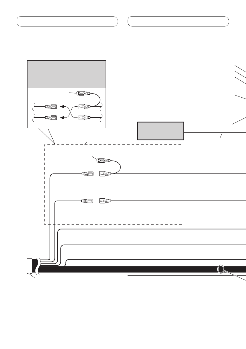
Power cable connection
Note
Depending on the kind of vehicle,
the function of 3* and 5* may be
different. In this case, be sure to
connect 2* to 5* and 4* to 3*.
1*
3* 2*
4*5*
Connect leads of the same
color to each other.
Cap (1*)
Do not remove cap if
this terminal is not in
use.
Yellow (3*)
Back-up (or
accessory)
Red (5*)
Accessory (or
back-up)
Orange/white
Connect to lighting switch terminal.
Multi-CD player
(sold separately)
Yellow (2*)
Connect to the constant
12 V supply terminal.
Red (4*)
Connect to terminal controlled by
ignition switch (12 V DC).
Front output
Rear output
Subwoofer output
Antenna jack
IP-BUS input (Blue)
IP-BUS cable
Black (chassis ground)
Connect to a clean, paint-free metal location.
ISO connector
Note
In some vehicles, the ISO connector
may be divided into two. In this case,
be sure to connect to both connectors.
Yellow/black
If you use an equipment with Mute
function, wire this lead to the Audio
Mute lead on that equipment. If not,
keep the Audio Mute lead free of any
connections.
4
Page 5
Connecting the units
English
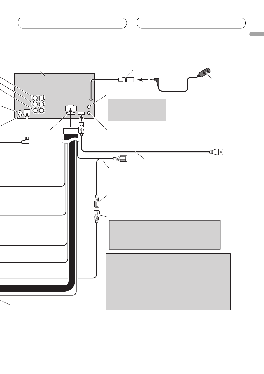
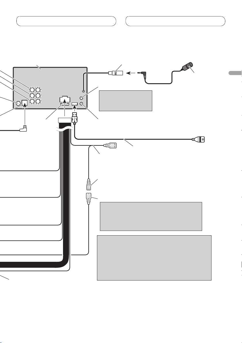
This product
Fuse (10 A)
14 cm
AUX jack (3.5 ø)
Use a stereo mini
plug cable to connect
with auxiliary device.
Wired remote input
Hard-wired remote control adaptor can
be connected (sold separately).
Blue/white
Connect to system control terminal of the
power amp (max. 300 mA 12 V DC).
Blue/white (7*)
Connect to auto-antenna relay control
terminal (max. 300 mA 12 V DC).
Blue/white (6*)
The pin position of the ISO connector will differ
depends on the type of vehicle. Connect 6* and
7* when Pin 5 is an antenna control type. In
another type of vehicle, never connect 6* and 7*.
Microphone input
4 m
USB cable
Connect to separately sold USB device.
1.5 m
Microphone
Speaker leads
White: Front left
White/black: Front left
Gray: Front right
Gray/black: Front right
Green: Rear left or subwoofer
Green/black: Rear left or subwoofer
Violet: Rear right or subwoofer
Violet/black: Rear right or subwoofer
Notes
• Change the initial setting of this unit (refer to the
operation manual). The subwoofer output of this
unit is monaural.
• When using a subwoofer of 70 W (2 Ω), be sure to
connect with Violet and Violet/black leads of this
unit. Do not connect anything with Green and
Green/black leads.
5
Page 6
Connecting the units
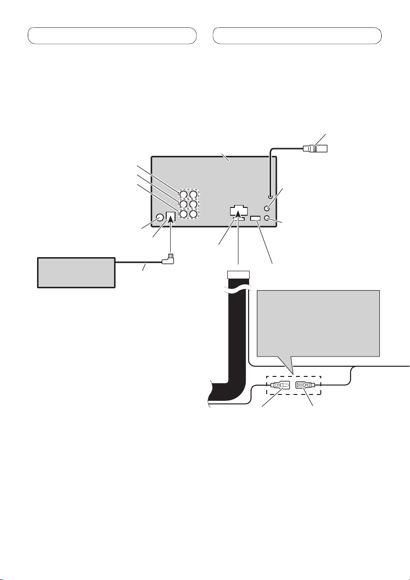
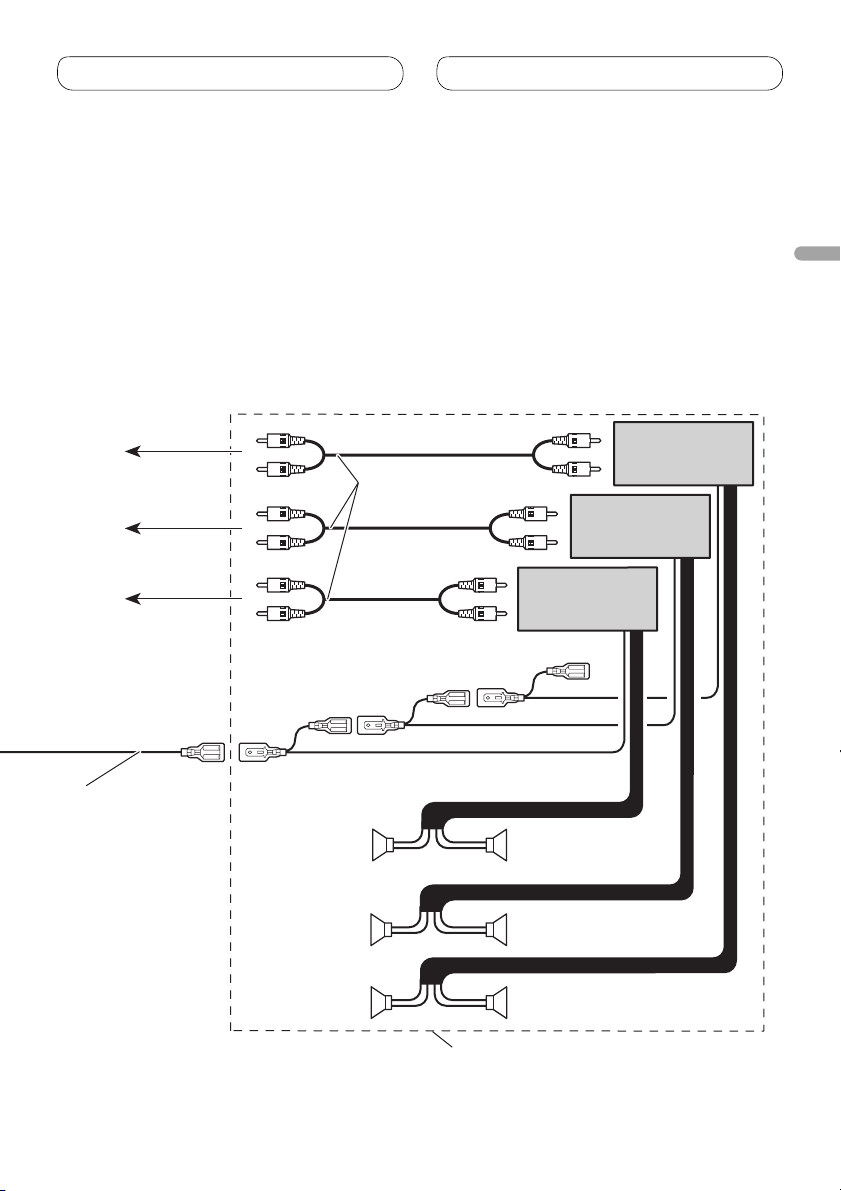
Connecting to separately sold power amp
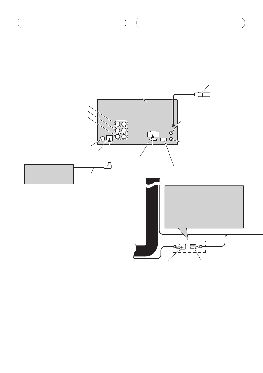
This product
Front output
Rear output
Subwoofer output
Microphone input
(Refer to page 4 to 5.)
14 cm
AUX jack (3.5 ø)
(Refer to page 4 to 5.)
Antenna jack
IP-BUS input (Blue)
Multi-CD player
(sold separately)
IP-BUS cable
Refer to page 4 to 5.
Fuse (10 A)
Refer to page 4 to 5.
The pin position of the ISO
connector will differ depends on
the type of vehicle. Connect 6*
and 7* when Pin 5 is an antenna
control type. In another type of
vehicle, never connect 6* and 7*.
Blue/white (6*)
Wired remote input
Hard-wired remote control
adaptor can be connected
(sold separately).
Blue/white (7*)
Connect to auto-antenna
relay control terminal
(max. 300 mA 12 V DC).
6
Page 7
Connecting the units
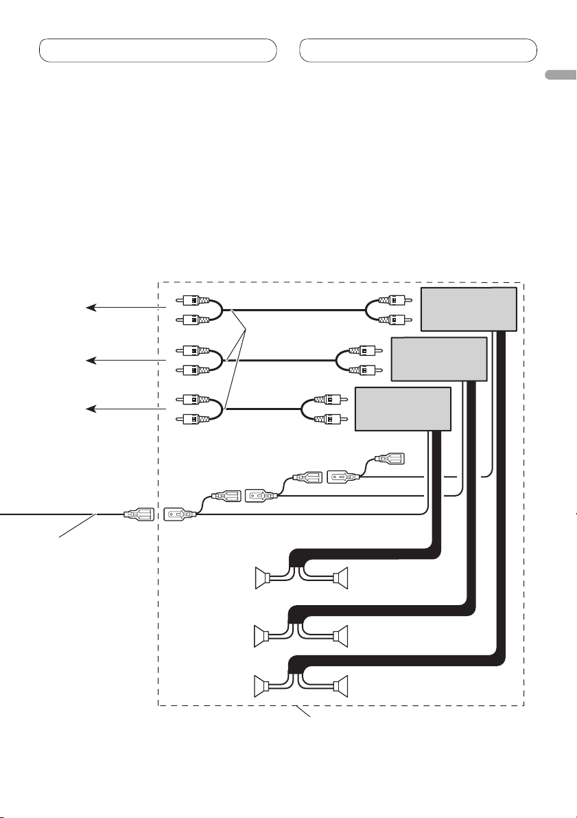
To subwoofer
output
To rear output
To front output
Connect with RCA cables
(sold separately)
English
Power amp
(sold separately)
Power amp
(sold separately)
Power amp
(sold separately)
Blue/white
Connect to system
control terminal of
the power amp (max.
300 mA 12 V DC).
System remote control
Front speaker
Rear speaker
Subwoofer
Front speaker
Rear speaker
Subwoofer
Perform these connections when using
the optional amplifier.
7
Page 8
Installation
Note
• Check all connections and systems before final
installation.
• Do not use unauthorized parts. The use of
unauthorized parts may cause malfunctions.
• Consult with your dealer if installation requires
drilling of holes or other modifications of the
vehicle.
• Do not install this unit where:
— it may interfere with operation of the vehicle.
— it may cause injury to a passenger as a result
of a sudden stop.
• Do not install the display where it may (i) obstruct
the driver’s vision, (ii) impair the performance of
any of the vehicle’s operating systems or safety
features, including air bags, hazard lamp buttons
or (iii) impair the driver’s ability to safely operate
the vehicle.
• The semiconductor laser will be damaged if it
overheats. Install this unit away from hot places
such as near the heater outlet.
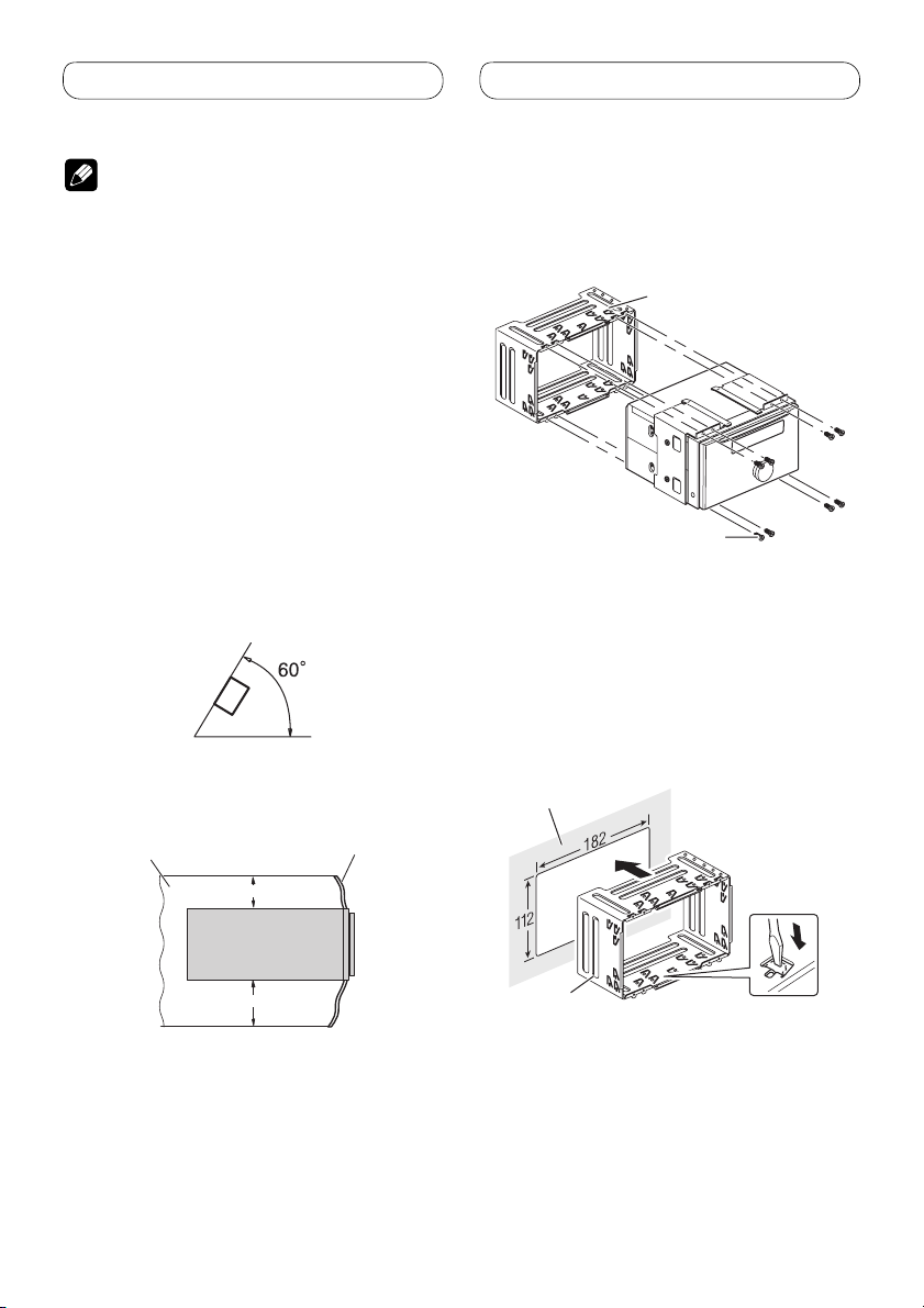
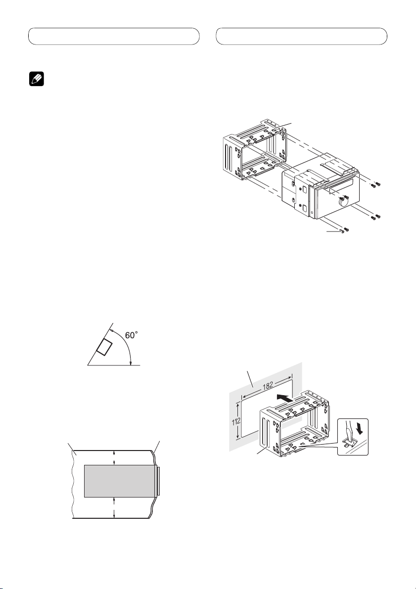
• Optimum performance is obtained when the unit
is installed at an angle of less than 60°.
• When installing, to ensure proper heat dispersal
when using this unit, make sure you leave ample
space behind the rear panel and wrap any loose
cables so they are not blocking the vents.
Leave ample space
Dashboard
Before installing this unit
•
Remove the holder.
Loosen the screws (3 × 6 mm) to remove the
holder.
Holder
Screw (3 × 6 mm)
Installation with the holder
and side bracket
1. Install the holder into the dashboard.
After inserting the holder into the dashboard,
select and bend the tabs appropriate to the
thickness of the dashboard material. (Install
this unit as firmly as possible using the top
and bottom tabs. To secure this unit, bend the
tabs 90 degrees.)
Dashboard
5cm
10cm
Holder
8
Page 9
Installation
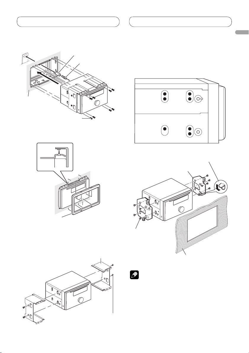
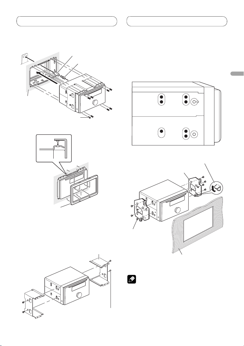
2. Install this unit and fasten the screws.
Rubber bush
Double-ended screw
Dashboard
Screw (3 × 6 mm)
3. Attach the trim ring.
2. Fastening the unit to the factory
radio-mounting bracket.
Position the unit so that its screw holes are
aligned with the screw holes of the bracket,
and tighten the screws at 3 or 4 locations on
each side.
If the pawl gets in the way,
bend it down.
Factory radio
mounting bracket
English
Trim ring
Installation using the screw
holes on the side of the unit
1. Remove the side brackets.
Side bracket
Screw for fixing the side
bracket (5 × 8 mm)
Binding screw or
flush surface screw
Be sure to use the
screws supplied
with this unit.
Dashboard or console
Note
In some types of vehicles, discrepancy may
occur between the unit and the dashboard. If this
happens, use the supplied frame to fill the gap.
9
Page 10
Installation
Installing the microphone
Installation notes
Install the microphone in a position and
orientation that will enable it to pick up the
voice of the person operating the system.
CAUTION
It is extremely dangerous to allow the
microphone lead to become wound around
the steering column or gearstick. Be sure to
install the unit in such a way that it will not
obstruct driving.
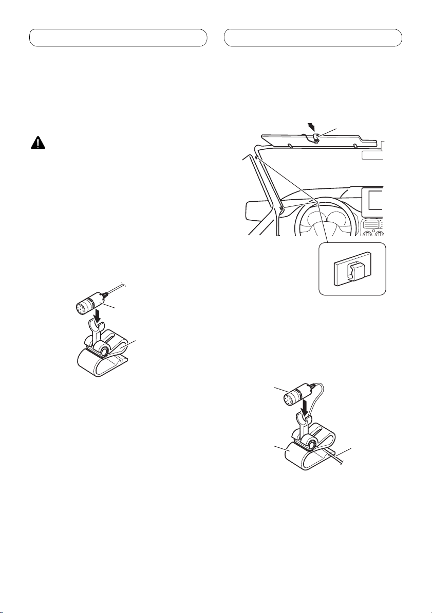
When installing the microphone
on the sun visor
1. Install the microphone on the
microphone clip.
Microphone
Microphone clip
2. Install the microphone clip on the sun
visor.
With the sun visor up, install the microphone
clip. (Lowering the sun visor reduces the
recognition rate for voice operations.)
Microphone clip
Clamps
Use clamps to secure
the lead where necessary
inside the vehicle.
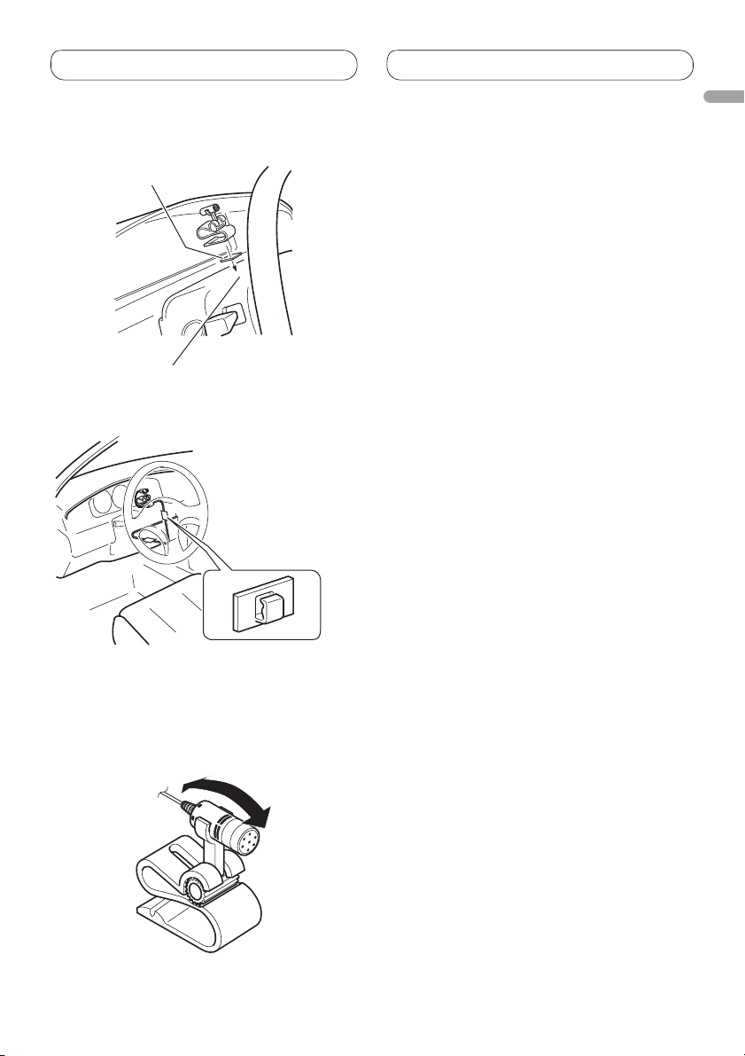
When installing the microphone
on the steering column
1. Install the microphone on the
microphone clip.
10
Microphone
Microphone clip
Fit the microphone
lead into the groove.
Page 11
Installation
2. Install the microphone clip on the
steering column.
Double-sided tape
Install the microphone clip on the
rear side of the steering column.
Clamps
Use clamps to secure
the lead where
necessary inside the
vehicle.
English
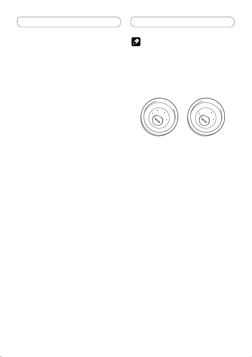
Adjusting the microphone
angle
The microphone angle can be adjusted by
moving forward or backward the microphone
clip angle.
11
Page 12
Contenido
Conexión de las unidades
Conexión de las unidades ................... 2
Conexión del cable de alimentación .............. 4
Conexión al amplificador de potencia
vendido separadamente
......................................
Instalación .............................................. 8
Antes de instalar esta unidad ........................ 8
Instalación con el sujetador y
ménsula lateral ........................................... 8
Instalación con agujeros de tornillo
en el lado de la unidad............................... 9
Instalación del micróphono .......................... 10
Cuando instale el micrófono en la visera .....10
Cuando instale el micrófono en la base
del volante ................................................. 10
Ajuste del ángulo del micrófono .................. 11
Nota
• Cuando se instale esta unidad en un vehículo
6
sin la posición ACC (accesorio) en el interruptor
de encendido, se debe conectar el cable rojo al
terminal que puede detectar la operación de la
llave de encendido.
De lo contrario, la batería puede descargarse.
C
C
A
O
F
N
F
O
Posición ACC
S
T
A
R
T
Sin posición ACC
• El uso de esta unidad en condiciones diferentes
de las siguientes podría causar un fuego o fallo de
funcionamiento.
— Vehículos con una batería de 12 voltios y
puesta a tierra negativa.
— Altavoz con 50 W (valor de salida) y de 4 a 8
ohmios (valor de impedancia).
• Para prevenir cortocircuitos, sobrecalentamiento
o fallo de funcionamiento, asegúrese de seguir las
instrucciones a continuación.
— Desenchufe el terminal negativo de la batería
antes de la instalación.
— Fije el cableado con abrazaderas de cable o
con cinta adhesiva. Para proteger el cableado,
envuélvalo con cinta adhesiva donde el
cableado se apoya sobre piezas metálicas.
— Posicione todos los cables alejados de las
piezas móviles, como el cambio de marchas y
rieles de los asientos.
— Posicione todos los cables alejados de
lugares calientes como cerca de la salida del
calentador.
— No pase el cable amarillo a través de un
agujero en el compartimiento del motor para
conectar la batería.
— Cubra cualquier conector de cable
desconectado con cinta de aislamiento.
— No acorte ningún cable.
— No corte nunca el aislamiento del cable de
alimentación de esta unidad para compartir
la energía con otro equipo. La capacidad de
corriente del cable es limitada.
— Utilice un fusible con la capacidad
especificada.
— No conecte nunca el cable negativo de altavoz
directamente a la puesta a tierra.
— No junte nunca múltiples cables negativos de
altavoz.
O
F
N
F
O
S
T
A
R
T
2
Page 13

Conexión de las unidades
• La señal de control se emite a través del cable
azul/blanco cuando se enciende esta unidad.
Conéctelo a un terminal de control de sistema de
amplificador de potencia externo o al terminal de
control de relé de antena automática del vehículo
(máx. 300 mA, 12 V CC). Si el vehículo está
equipado con una antena de vidrio, conéctelo al
terminal de suministro de potencia de refuerzo de
la antena.
• No conecte nunca el cable azul/blanco al
terminal de alimentación de un amplificador
de potencia externo. Igualmente, no conéctelo
nunca al terminal de alimentación de la antena
automática.
De lo contrario, puede ocurrir la descarga de la
batería o un fallo de funcionamiento.
• Los conectores IP-BUS están codificados en
colores. Asegúrese de conectar los conectores del
mismo color.
• El cable negro es para la puesta a tierra. Se debe
conectar este cable y el cable de puesta a tierra
de otro producto (especialmente de productos de
alta corriente como un amplificador de potencia)
separadamente. De lo contrario, puede ocurrir un
fuego o fallo de funcionamiento si los cables se
sueltan accidentalmente.
Español
3
Page 14
Conexión de las unidades
Conexión del cable de alimentación
Nota
Dependiendo del tipo de vehículo, la
función de 3* y 5* puede ser
diferente. En este caso, asegúrese de
conectar 2* a 5* y 4* a 3*.
1*
3* 2*
4*5*
Conecte los hilos del mismo
color a cada otro.
Tapa (1*)
No quite la tapa
cuando no se utiliza
este terminal.
Amarillo (3*)
Reserva
(o accesorio)
Rojo (5*)
Accesorio
(o reserva)
Rojo (4*)
Conecte al terminal controlado por del
interruptor de encendido (12 V CC).
Anaranjado/blanco
Conecte al terminal de interruptor de iluminación.
Reproductor de
Multi-CD (vendido
separadamente)
Amarillo (2*)
Conecte el terminal de suministro
de 12 V constante.
Salida delantera
Salida trasera
Salida de altavoz de subgrave
Toma de antena
Entrada IP-BUS (Azul)
Cable IP-BUS
Negro (masa de la carrocería)
Conecte a un punto de metal limpio, libre de pintura.
Conector ISO
Nota
En algunos vehículos, puede que el
conector ISO esté dividido en dos. En
este caso, asegúrese de conectar a
ambos conectores.
Amarillo/negro
Si se utiliza un equipo con función de
silenciamiento, conecte este conductor
con el conductor de silenciamiento de
audio en tal equipo. Si no, mantenga el
enmudecimiento de audio libre de
cualquier conexión.
4
Page 15
Conexión de las unidades
Este producto
Fusible (10 A)
14 cm
Jack AUX (3.5 ø)
Utilice un cable con
clavija mini estéreo
con el equipo auxiliar.
Entrada remota cableada
Se puede conectar el adaptador de control
remoto cableado (vendido separadamente).
Azul/blanco
Conecte al terminal de control de sistema del
amplificador de potencia (máx. 300 mA 12 V CC).
Azul/blanco (7*)
Conecte al terminal de control de relé de
antena automática (máx. 300 mA 12 V CC).
Azul/blanco (6*)
La posición de los contactos del conector ISO
difiere dependiendo del tipo del vehículo. Conecte
6* y 7* cuando el contacto 5 es del tipo de control
de antena. En otros tipos de vehículo, no conecte
nunca 6* y 7*.
Entrada del micrófono
4 m
Cable USB
Conecte al dispositivo USB vendido
separamente.
1,5 m
Micrófono
Español
Notas
• Cambie el ajuste inicial de esta unidad (refiérase al
manual de operación). La salida de altavoz de
subgraves de esta unidad es monofónica.
• Cuando utilice un altavoz de subgraves de 70 W
(2 Ω), asegúrese de conectarlo con los hilos Violeta
y Violeta/negro de esta unidad. No conecte nada
Hilos de altavoz
Blanco: Izquierda delantera
Blanco/negro: Izquierda delantera
Gris: Derecha delantera
Gris/negro: Derecha delantera
Verde: Izquierda trasera o altavoz de subgraves
Verde/negro: Izquierda trasera o altavoz de subgraves
Violeta: Derecha trasera o altavoz de subgraves
Violeta/negro: Derecha trasera o altavoz de subgraves
con los hilos Verde y Verde/negro.
5
Page 16
Conexión de las unidades
Conexión al amplificador de potencia vendido separadamente
Entrada del micrófono
(Consulta la página 4 a 5.)
Este producto
Salida delantera
Salida trasera
Salida de altavoz de subgrave
14 cm
Jack AUX (3.5 ø)
(Consulta la página 4 a 5.)
Toma de antena
Entrada IP-BUS (Azul)
Reproductor de
Multi-CD (vendido
separadamente)
Fusible (10 A)
Cable IP-BUS
Consulta la página 4 a 5.
Consulta la página 4 a 5.
La posición de los contactos del
conector ISO difiere dependiendo
del tipo del vehículo. Conecte 6* y
7* cuando el contacto 5 es del tipo
de control de antena. En otros
tipos de vehículo, no conecte
nunca 6* y 7*.
Azul/blanco (6*)
Entrada remota cableada
Se puede conectar el
adaptador de control remoto
cableado (vendido
separadamente).
Azul/blanco (7*)
Conecte al terminal de control
de relé de antena automática
(máx. 300 mA 12 V CC).
6
Page 17
Conexión de las unidades
A la salida del
altavoz de
subgraves
A la salida trasera
A la salida delantera
Conecte los cables RCA
(vendidos separadamente)
Español
Amplificador de
potencia (vendido
separadamente)
Amplificador de
potencia (vendido
separadamente)
Amplificador de
potencia (vendido
separadamente)
Azul/blanco
Conecte al terminal de
control de sistema del
amplificador de
potencia (máx. 300 mA
12 V CC).
Control remoto de sistema
Altavoz delantero
Altavoz trasero
Altavoz de
subgraves
Altavoz delantero
Altavoz trasero
Altavoz de
subgraves
Realice estas conexiones cuando utilice
el amplificador opcional.
7
Page 18
Instalación
Nota
• Verifique todas las conexiones y sistemas antes
de la instalación final.
• No utilice piezas no autorizadas. El uso de
piezas no autorizadas puede causar un fallo de
funcionamiento.
• Consulte su revendedor si se requiere taladrar
agujeros o hacer otras modificaciones del
vehículo para la instalación.
• No instale esta unidad donde:
— pueda interferir con la operación del vehículo.
— pueda causar lesiones a un pasajero en el caso
de una parada brusca.
• No instale el display en un lugar que (i) pueda
obstaculizar la visión del conductor, (ii) pueda
alterar el funcionamiento de los sistemas
operativos o los dispositivos de seguridad del
vehículo, en particular las bolsas de aire y los
botones de luces de seguridad o (iii) pueda
afectar la capacidad del conductor para manejar
el vehículo de manera segura.
• El láser semiconductor se dañará si se
sobrecalienta. Instale esta unidad alejada de
lugares calientes como cerca de la salida del
calentador.
• Se obtiene el rendimiento óptimo cuando se
instala la unidad en un ángulo inferior a 60°.
• Cuando instale, para asegurar la dispersión
apropiada del calor durante el uso de esta unidad,
asegúrese de dejar un amplio espacio por detrás
del panel trasero y enrolle cualesquiera cables
sueltos de modo que no bloque en las aberturas de
ventilación.
Deje un amplio espacio
Tablero de
instrumentos
Antes de instalar esta unidad
•
Saque el sujetador.
Afloje los tornillos (3 × 6 mm) para sacar el
sujetador.
Sujetador
Tornillo (3 × 6 mm)
Instalación con el sujetador y
ménsula lateral
1. Instale el sujetador en el tablero de
instrumentos.
Después de insertar el sujetador en el tablero
de instrumentos, seleccione y doble las
lengüetas de acuerdo con el espesor del
material del tablero de instrumentos. (Instale
esta unidad lo más firme posible utilizando
las lengüetas superior e inferior. Para fijar
esta unidad, doble las lengüetas 90 grados.)
Tablero de
instrumentos
5cm
10cm
Sujetador
8
Page 19
Instalación
2. Instale esta unidad y apriete los
tornillos.
Buje de caucho
Prisionero
Tablero de
instrumentos
Tornillo (3 × 6 mm)
3. Fije el anillo de compensación.
Anillo de
compensación
2. Fijación de la unidad a la ménsula de
montaje de radio de fábrica.
Posicione la unidad de modo que los agujeros
de tornillo se alineen con los agujeros de
tornillo de la ménsula y, a continuación,
apriete los tornillos en 3 ó 4 puntos en cada
lado.
Español
Si el trinquete se pone en el
camino, dóblelo hacia abajo.
Ménsula de montaje
de radio de fábrica
Instalación con agujeros
de tornillo en el lado de la
unidad
1. Saque las ménsulas laterales.
Ménsula lateral
Tornillo para fijar la ménsula
lateral (5 × 8 mm)
Tornillo de apriete
o tornillo de cabeza
embutida
Asegúrese de
utilizar los tornillos
suministrados con
esta unidad.
Tablero de instrumentos
o consola
Nota
En algunos tipos de vehículos, puede que ocurra
una discrepancia entre la unidad y el tablero de
instrumentos. Si esto ocurre, utilice el bastidor
suministrador para llenar el huelgo.
9
Page 20

Instalación
Instalación del micróphono
Notas acerca de la instalación
Instale el micrófono en una posición u
orientatión que permita captar bien las voces de
la persona que utilice el sistema mediante voz.
PRECAUCIÓN
Es peligrosísimo dejar que el cable del
micrófono se enrolle en la base del volante
o en la palanca de cambios. Asegúrese de
instalar la unidad de forma que ésta no sea
un obstáculo para la conducción.
Cuando instale el micrófono
en la visera
1. Instale el micrófono en la presilla de
micrófono.
Micrófono
Presilla de micrófono
2. Instale la presilla de micrófono en la
visera.
Con la visera hacia arriba,instale la presilla
del micrófono. (Al bajar la visera se reduce
la capacidad de reconocimiento para las
operaciones mediante voz).
Presilla de micrófono
Abrazaderas
Utilice abrazaderas
para asegurar el cable
en el interior del
vehículo donde sea
necesario.
Cuando instale el micrófono
en la base del volante
1. Instale el micrófono en la presilla de
micrófono.
10
Micrófono
Presilla de
micrófono
Fije el cable del
micrófono en la
ranura.
Page 21

Instalación
2. Instale la presilla de micrófono en la
base del volante.
Cinta con adhesivo de doble cara
Instale la presilla del micrófono en
el lado trasero de la base del volante.
Abrazaderas
Utilice abrazaderas
para asegurar el
cable en el interior
del vehículo donde
sea necesario.
Español
Ajuste del ángulo del
micrófono
Se puede ajustar del micrófono moviendo
el ángulo de la presilla del micrófono hacia
delante o hacia atrás.
11
Page 22
Inhalt
Anschließen der Geräte
Anschließen der Geräte ....................... 2
Anschluss des Stromkabels .......................... 4
Anschluss an einen getrennt erhältlichen
Leistungsverstärker
........................................
Einbauverfahren .................................... 8
Vor der Installation dieses Geräts .................. 8
Installation mit der Halterung und
Seitenhalterung ......................................... 8
Installation mit Hilfe der Schraubenlöcher
an den Seiten des Geräts ......................... 9
Einbau des Mikrofons ................................... 10
Befestigung des Mikrofons an der
Sonnenblende ...........................................10
Befestigung des Mikrofons an der
Lenksäule .................................................. 10
Einstellung des Mikrofonwinkels ................. 11
Hinweise
• Wenn dieses Gerät in einem Auto eingebaut wird,
6
as auf dem Zündschalter keine ACC (Zubehör)Position hat, sollte die rote Leitung des Geräts
an eine Klemme angeschlossen werden, die die
Position des Zündschalters erfassen kann.
Anderenfalls kann die Autobatterie entleert
werden.
C
C
A
O
F
N
F
O
ACC-Position
S
T
A
R
T
O
Keine A
• Wenn das Gerät nicht unter den folgenden
Bedingungen eingebaut wird, kann ein Brand
oder eine Funktionsstörung auftreten.
— Fahrzeuge mit einer 12-Volt-Batterie und
negativer Erdung.
— Lautsprecher mit 50 W (Ausgangsleistung)
und 4 bis 8 Ohm (Impedanz).
• Um Kurzschlüsse, eine Überhitzung oder
Funktionsstörung zu verhindern, befolgen Sie bitte
die folgenden Hinweise:
— Trennen Sie die negative Klemme der Batterie
vor dem Einbau ab.
— Sichern Sie die Leitungen mit Kabelklemmen
oder Klebeband. Zum Schutz der Leitungen
sollten sie an Stellen, wo sie Metallteile
berühren, mit Klebeband umwickelt werden.
— Verlegen Sie alle Leitungen so, dass keine
beweglichen Teile, wie die Gangschaltung und
die Sitzschienen, berühren.
— Verlegen Sie alle Kabel so, dass sie von heißen
Stellen, wie etwa der Heizungsauslassöffnung
entfernt sind.
— Führen Sie die gelbe Leitung zum Anschluss
an die Batterie nicht durch ein Loch in den
Motorraum ein.
— Umwickeln Sie abgetrennte Leitungen mit
Isolierband.
— Verkürzen Sie keine Kabel.
— Führen Sie niemals anderen Geräten
Strom zu, indem Sie die Isolierung der
Stromversorgungsleitung dieses Geräts
durchschneiden und davon Strom abzapfen.
Die Strombelastbarkeit der Leitung ist
begrenzt.
— Verwenden Sie eine Sicherung mit dem
vorgeschriebenen Nennwert.
F
F
CC-Position
O
N
S
T
A
R
T
2
Page 23

Anschließen der Geräte
— Schließen Sie das negative Lautsprecherkabel
nie direkt an die Erdung an.
— Bündeln Sie nie die negativen Kabeln
mehrerer Lautsprecher.
• Das Steuersignal wird über das blaue/
weiße Kabel ausgegeben, wenn dieses
Geräts eingeschaltet wird. Schließen Sie
es an eine System-Fernbedienung eines
externen Leistungsverstärkers oder an die
Autoantennenrelais-Steuerungsklemme
des Fahrzeugs an (max. 300 mA, 12 V
Gleichspannung). Wenn das Fahrzeug
mit einer Fensterantenne ausgestattet ist,
schließen Sie es an die AntennenverstärkerStromversorgungsklemme an.
• Schließen Sie das blaue/weiße Kabel nie an
die Leistungsklemme des Verstärkers an.
Außerdem darf das blaue/weiße Kabel nicht
an die Leistungsklemme der Auto-Antenne
angeschlossen werden. Ein solcher Anschluss
könnte zu einer Belastung der Batterie führen und
Funktionsstörungen verursachen.
• Die IP-BUS-Leitungen sind farbcodiert. Achten
Sie immer darauf, Leitungen derselben Farbe
miteinander zu verbinden.
• Das schwarze Kabel ist das Erdungskabel. Dieses
Kabel ist getrennt von der Erde von HochstromGeräten, wie z. B. Leistungsverstärkern, zu
erden. Anderenfalls besteht die Gefahr einer
Beschädigung der Geräte oder eines Brandes,
falls die Erdungsstelle versehentlich abgetrennt
wird.
Deutsch
3
Page 24

Anschließen der Geräte
Anschluss des Stromkabels
Hinweis
Je nach Art des Fahrzeugs besitzen
3* und 5* u. U. unterschiedliche
Funktionen. Verbinden Sie in einem
solchen Fall 2* mit 5* und 4* mit 3*.
1*
3* 2*
4*5*
Verbinden Sie Leitungen
derselben Farbe miteinander.
Kappe (1*)
Wenn dieser Steckverbinder
nicht verwendet wird,
lassen Sie die Kappe
aufgesetzt.
Gelb (3*)
Reserve
(oder Zubehör)
Rot (5*)
Zubehör
(oder Reserve)
Rot (4*)
An eine Stromversorgung anschließen,
(12 V Gleichspannung), die mit dem
Zündschloss ein-/ausgeschaltet wird.
Orangefarben/weiß
An die Lichtschalterklemme anschließen.
Ausgang für vorderen Zusatzlautsprecher
Ausgang für hintere Zusatzlautsprecher
Multi-CD-Player
(getrennt erhältlich)
Gelb (2*)
An eine Stromversorgung anschließen,
die immer Gleichstrom von 12 V führt.
Subwoofer-Ausgang
Antennebuchse
IP-BUS-Eingang (Blau)
IP-BUS-Kabel
Schwarz (Erdung)
An ein sauberes Metallteil anschließen, das von Farbe frei ist.
ISO-Anschluss
Hinweis
Bei einigen Fahrzeugen kann der
ISO-Steckverbinder in zwei Hälften geteilt
sein. In diesem Fall ist der Anschluss
unbedingt an beiden Steckverbindern
vorzunehmen.
Gelb/schwarz
Falls Sie ein Gerät mit Stummschaltfunktion
(Mute) verwenden, verdrahten Sie dieses Kabel
mit der Audio Mute-Leitung am entsprechenden
Gerät. Andernfalls die Audio Mute-Leitung frei
von Anschlüssen lassen.
4
Page 25

Anschließen der Geräte
Dieses Produkt
Sicherung
(10 A)
14 cm
AUX-Buchse (3.5 ø)
Zur Verbindung mit
Zusatzausrüstung
verwenden Sie ein
Stereo-Ministeckerkabel.
Buchse für die verdrahtete Fernbedienung
Hier kann ein Drahtfernbedienungsadapter
(getrennt erhältlich) angeschlossen werden.
Blau/weiß
An den Systemsteuerungs-Anschluss des
Leistungsverstärkers (max. 300 mA, 12 V
Gleichspannung) anschließen.
Blau/weiß (7*)
An die die Autoantennenrelais-Steuerungsklemme
anschließen (max. 300 mA, 12 V Gleichspannung).
Blau/weiß (6*)
Die Pin-Position des ISO-Anschlusses hängt vom
Fahrzeugtyp ab. 6* und 7* anschließen, wenn es
sich bei Pin 5 um einen Antennensteuerungstyp
handelt. Bei einem anderen Fahrzeugtyp 6* und
7* niemals anschließen.
Mikrofoneingang
4 m
USB-Kabel
Für den Anschluss an das separat
erhältliche USB-Gerät.
1,5 m
Mikrofon
Deutsch
Hinweise
• Ändern Sie die Grundeinstellung dieses Geräts (siehe
Bedienungsanleitung). Der Subwoofer-Ausgang dieses
Geräts ist Mono.
• Bei Verwendung eines Subwoofers von 70 W (2 Ω)
achten Sie darauf, den Anschluss an die violetten und
violetten/schwarzen Leitungen dieses Geräts
Lautsprecherzuleitungen
Weiß: Vorne links
Weiß/Schwarz: Vorne links
Grau: Vorne rechts
Grau/Schwarz: Vorne rechts
Grün: Hinten links oder Subwoofer
Grün/Schwarz: Hinten links oder Subwoofer
Violett: Hinten rechts oder Subwoofer
Violett/Schwarz: Hinten rechts oder Subwoofer
herzustellen. Stellen Sie keinen Anschluss mit den
grünen und grünen/schwarzen Leitungen her.
5
Page 26

Anschließen der Geräte
Anschluss an einen getrennt erhältlichen Leistungsverstärker
Mikrofoneingang
(Siehe Seite 4 und 5.)
14 cm
AUX-Buchse (3.5 ø)
(Siehe Seite 4 und 5.)
Buchse für die verdrahtete
Fernbedienung
Hier kann ein
Drahtfernbedienungsadapter
(getrennt erhältlich)
angeschlossen werden.
Siehe Seite 4 und 5.
Die Pin-Position des
ISO-Anschlusses hängt vom
Fahrzeugtyp ab. 6* und 7*
anschließen, wenn es sich bei Pin 5
um einen Antennensteuerungstyp
handelt. Bei einem anderen
Fahrzeugtyp 6* und 7* niemals
anschließen.
Ausgang für vorderen
Zusatzlautsprecher
Ausgang für hintere
Zusatzlautsprecher
Subwoofer-Ausgang
Antennebuchse
IP-BUS-Eingang (Blau)
Multi-CD-Player
(getrennt erhältlich)
Dieses Produkt
Sicherung (10 A)
IP-BUS-Kabel
Siehe Seite 4 und 5.
Blau/weiß (6*)
Blau/weiß (7*)
An die die
AutoantennenrelaisSteuerungsklemme
anschließen (max. 300 mA,
12 V Gleichspannung).
6
Page 27

Anschließen der Geräte
Zum
Subwoofer-Ausgang
Zum hinteren
Ausgang
Zum vorderen
Ausgang
Mit RCA-Kabeln verbinden
(getrennt erhältlich)
Deutsch
Leistungsverstärker
(getrennt erhältlich)
Leistungsverstärker
(getrennt erhältlich)
Leistungsverstärker
(getrennt erhältlich)
Blau/weiß
An den
SystemsteuerungsAnschluss des
Leistungsverstärkers
(max. 300 mA, 12 V
Gleichspannung)
anschließen.
System-Fernbedienung
Vorderer
Lautsprecher
Hinterer
Lautsprecher
Subwoofer
Vorderer
Lautsprecher
Hinterer
Lautsprecher
Subwoofer
Bei Gebrauch des optionalen Verstärkers
diese Anschlüsse vornehmen.
7
Page 28

Einbauverfahren
Hinweise
• Überprüfen Sie alle Anschlüsse und Systeme,
bevor Sie das Gerät endgültig einbauen.
• Verwenden Sie keine unautorisierten Teile. Die
Verwendung von unautorisierten Teilen kann zu
Funktionsstörungen führen.
• Wenden Sie sich an Ihren Fachhändler, wenn zum
Einbau des Geräts Löcher gebohrt oder andere
Veränderungen an Ihrem Auto vorgenommen
wenden müssen.
• Bauen Sie das Gerät nicht an einer Stelle ein, wo:
— es den Fahrer beim Fahren behindert.
— es den Beifahrer bei plötzlichem Bremsen
verletzen kann.
• Bringen Sie das Display nicht an Orten an, wo
es (i) die Sicht des Fahrers behindern, (ii) die
Funktionen des Fahrzeugbetriebssystems oder
der Sicherheitseinrichtungen, einschließlich der
Airbags und Warnblinkanlagenschalter stören,
oder (iii) die Fähigkeit des Fahrers zur sicheren
Lenkung des Fahrzeugs beeinträchtigen kann.
• Der Halbleiterlaser wird bei Überhitzung
beschädigt. Bauen Sie das Gerät daher nicht an
einer Stelle ein, wo es heiß wird, z. B. in der Nähe
einer Heizungsauslassöffnung.
• Die optimale Leistung wird erzielt, wenn der
Einbauwinkel nicht mehr als 60° beträgt.
• Damit die bei Betrieb dieses Geräts entwickelte
Wärme richtig abgeleitet werdenkann, sorgen Sie
beim Einbau dafür, dass ausreichend Platz hinter
der Rückwand bleibt, und wickeln Sie lockere
Kabel so, dass diesekeine Öffnungen blockieren
können.
Reichlich Platz lassen
Armaturenbrett
Vor der Installation dieses Geräts
• Entfernen Sie die Halterung.
Lockern Sie die Schrauben (3 × 6 mm), um
die Halterung zu entfernen.
Halterung
Schraube (3 × 6 mm)
Installation mit der Halterung
und Seitenhalterung
1. Setzen Sie die Halterung in das
Armaturenbrett ein.
Nachdem Sie die Halterung in das
Armaturenbrett eingeführt haben, wählen und
verbiegen Sie die Laschen, die für die Dicke
des Armaturenbrettmaterials geeignet sind.
(Setzen Sie dieses Gerät so fest wie möglich
mit Hilfe der oberen und unteren Laschen ein.
Um dieses Gerät zu sichern, verbiegen Sie die
Laschen um 90 Grad.)
Armaturenbrett
5cm
10cm
Halterung
8
Page 29

Einbauverfahren
2. Setzen Sie dieses Gerät ein, und
ziehen Sie die Schrauben fest.
Gummibuchse
Doppelschraube
Armaturenbrett
Schraube (3 × 6 mm)
3. Befestigen Sie den Trimmring.
2. Befestigen Sie das Gerät an der
Radiomontagehalterung vom Werk.
Positionieren Sie das Gerät so, dass seine
Schraubenlöcher auf die Schraubenlöcher
der Halterung ausgerichtet sind, und ziehen
Sie die Schrauben an 3 oder 4 Stellen auf
jeder Seite fest.
Deutsch
Falls die Klinke im Wege sein sollte,
biegen Sie sie nach unten.
Radiomontagehalterung
vom Werk
Trimmring
Installation mit Hilfe der
Schraubenlöcher an den
Seiten des Geräts
1. Entfernen Sie die Seitenhalterungen.
Seitenhalterung
Schraube zum Befestigen der
Seitenhalterung (5 × 8 mm)
Klemmschraube oder
Senkschraube
Verwenden Sie
nur die mit diesem
Gerät mitgelieferten
Scrauben.
Armaturenbrett oder
Konsole
Hinweis
Bei einigen Fahrzeugen kann eine Abweichung
zwischen diesem Gerät und dem Armaturenbrett
auftreten. Falls dies der Fall ist, verwenden Sie den
mitgelieferten Rahmen, um den Spalt zu füllen.
9
Page 30

Einbauverfahren
Einbau des Mikrofons
Hinweise zum Einbau
Das Mikrofon an einem geeigneten Platz
anbringen und so ausrichten, dass es die
Stimme der Person, die das System über
Sprache steuert, gut aufnimmt.
VORSICHTSMASSNAHMEN
Es ist äußerst gefährlich, das Mikrofonkabel
um die Lenksäule oder den Gangschalthebel
zu wickeln. Beim Einbau unbedingt darauf
achten, dass das Gerät den Fahrer nicht
behindert.
Befestigung des Mikrofons an
der Sonnenblende
1. Das Mikrofon im Mikrofonklemmhalter
befestigen.
Mikrofon
Mikrofonklemmhalter
2. Den Mikrofonklemmhalter an der
Sonnenblende anklemmen.
Die Sonnenblende hochklappen und den
Mikrofonklemmhalter anklemmen. (Ein
Herunterklappen der Sonnenblendeverringert
die Empfangsempfindlichkeit des Mikrofons
bei der sprachgesteuerten Bedienung.)
Mikrofonklemmhalter
Kabelklemmen
Das Mikrofonkabel
mit Kabelklemmen im
Fahrzeuginnenraum
verlegen.
Befestigung des Mikrofons an
der Lenksäule
1. Das Mikrofon im Mikrofonklemmhalter
befestigen.
10
Mikrofon
Mikrofonklemmhalter
Das Mikrofonkabel in
die Kerbe einpassen.
Page 31

Einbauverfahren
2. Das Mikrofon an der Lenksäule
befestigen.
Doppelseitiger Klebestreifen
Den Mikrofonklemmhalter an der
Rückseite der Lenksäule befestigen.
Kabelklemmen
Das Mikrofonkabel
mit Kabelklemmen im
Fahrzeuginnenraum
verlegen.
Einstellung des
Mikrofonwinkels
Der Mikrofonwinkel kann durch Verändern
des Mikrofonklemmhalterwinkels eingestellt
werden.
Deutsch
11
Page 32

Table des matières
Connexions des appareils
Connexions des appareils ................... 2
Raccordement du câble d’alimentation ........ 4
Raccordement à un amplificateur de
puissance séparé
............................................
Installation ............................................. 8
Avant d’installer cet appareil ......................... 8
Installation en utilisant le support principal
et le support latéral ................................... 8
Installation à l’aide des perçages sur
le côté de l’appareil ................................... 9
Installation du microphone .......................... 10
Installation du microphone
sur le pare-soleil ........................................10
Installation du microphone sur la colonne
de direction ............................................... 10
Ajustement de l’angle du microphone ....... 11
Remarque
• Si cet appareil est installé dans un véhicule sans
6
position ACC (accessoire) sur le commutateur
d’allumage, le câble rouge doit être connecté
à une borne qui peut détecter la position du
commutateur d’allumage. Sinon, la batterie risque
de se décharger.
C
C
A
O
F
N
F
O
Position ACC
S
T
A
R
T
Pas de p
• Utiliser cet appareil dans d’autres conditions
que les conditions suivantes peut entraîner un
incendie ou un mauvais fonctionnement.
— Véhicule avec une batterie de 12 volts et une
mise à la masse négative.
— Enceintes de 50 W (valeur de sortie) et de 4
ohms à 8 ohms (valeur d’impédance).
• Pour éviter tout court-circuit, surchauffe ou
mauvais fonctionnement, assurez-vous de suivre
les instructions ci-dessous.
— Déconnectez la borne négative de la batterie
avant l’installation.
— Fixez solidement les câbles avec des serre-
câbles ou du ruban adhésif. Pour protéger
le câblage, entourez-le de ruban adhésif à
l’endroit où il est en contact avec des pièces
métalliques.
— Tenez tous les câbles à l’écart des parties
mobiles, telles que le levier de vitesse et les
rails des sièges.
— Tenez tous les câbles à l’écart des endroits
chauds, tels que les sorties du chauffage.
— Ne faites pas passer le câble jaune par un
trou dans le compartiment du moteur pour le
connecter à la batterie.
— Recouvrez tous les câbles non connectés avec
du ruban isolant.
— Ne raccourcissez aucun câble.
— Ne coupez jamais l’isolant du câble
d’alimentation de cet appareil afin partager
l’alimentation avec un autre appareil. La
capacité électrique du câble est limitée.
— Utilisez un fusible de la valeur donnée.
— Ne connectez jamais le câble négatif des
enceintes directement à la masse.
— N’attachez jamais ensemble plusieurs câbles
négatifs de plusieurs enceintes.
F
F
O
osition ACC
O
N
S
T
A
R
T
2
Page 33

Connexions des appareils
• Le signal de commande est sorti par le câble
bleu/blanc quand cet appareil est sous
tension. Connectez-le à la télécommande
d’un système d’amplification extérieur ou à la
prise de commande du contrôle de relais de
l’antenne automatique (max. 300 mA, 12 V CC).
Si le véhicule est équipée d’une antenne de
vitre, connectez-la à la prise d’alimentation de
l’amplificateur d’antenne.
• Ne connectez jamais le câble bleu/blanc à la prise
d’alimentation d’un amplificateur extérieur. Et
ne le connectez pas à la prise d’alimentation de
l’antenne automatique. Sinon, la batterie risque
de se décharger ou un mauvais fonctionnement
peut se produire.
• Les connecteurs IP-BUS sont codés par couleur.
Assurez-vous de connecter les connecteurs de
même couleur.
• Le câble noir est pour la masse. Ce câble et
les câbles de masse des autres produits (en
particulier les appareils à haute intensité tels
que les amplificateurs) doivent être câblés
séparément. Sinon, ils peuvent entraîner un
incendie ou un mauvais fonctionnement s’ils se
détachent.
Français
3
Page 34

Connexions des appareils
Raccordement du câble d’alimentation
Remarque
En fonction du type de véhicule, la
fonction de 3* et de 5* peut différer.
Sans ce cas, assurez-vous de
connecter 2* à 5* et 4* à 3*.
1*
3* 2*
4*5*
Connectez les câbles de la même
couleur les uns aux autres.
Capuchon (1*)
Ne retirez pas le
capuchon si cette prise
n’est pas utilisée.
Jaune (3*)
Secours
(ou accessoire)
Rouge (5*)
Accessoire
(ou secours)
Jaune (2*)
Connectez à une prise
d’alimentation constante 12 V.
Rouge (4*)
Connectez à une prise commandée par
le commutateur d’allumage (12 V CC).
Orange/blanc
Connectez à la prise du commutateur d’éclairage.
Lecteur de CD
à chargeur
(vendu séparément)
Sortie avant
Sortie arrière
Sortie du caisson de grave
Prise d’antenne
Entrée IP-BUS (Bleu)
Câble IP-BUS
Noire (masse au châssis)
Connectez à une section métallique propre et sans peinture.
Connecteur ISO
Remarque
Dans certains véhicule, le connecteur
ISO peut être divisé en deux. Dans ce
cas, assurez-vous de faire la connexion
aux deux connecteurs.
Jaune/noir
Si vous utilisez un appareil muni d’une
fonction de mise en sourdine, connectez
ce conducteur au conducteur de
sourdine audio de cet appareil. Sinon,
laisser le fil de mise en sourdine audio
sans aucune connexion.
4
Page 35

Connexions des appareils
Cet appareil
Fusible (10 A)
14 cm
Prise AUX (3.5 ø)
Utilisez un câble à fiches
stéréo mini pour raccorder
un appareil auxiliaire.
Entrée de télécommande câblée
Un adaptateur de télécommande câblée
peut être connecté (vendu séparément).
Bleu/blanc
Connectez à la prise de commande du système de
l’amplificateur de puissance (max. 300 mA 12 V CC).
Bleu/blanc (7*)
Connectez à la prise du contrôle de relais de
l’antenne automatique (max. 300 mA, 12 V CC).
Bleu/blanc (6*)
La position des broches du connecteur ISO diffère
en fonction du type de véhicule. Connectez 6* et
7* quand la broche 5 correspond à la commande
de l’antenne. Dans les autres cas, ne connectez
jamais 6* et 7*.
Entrée microphone
4 m
Câble USB
Connectez-le à un périphérique USB
vendu séparément.
1,5 m
Microphone
Français
Remarques
• Change le réglage initial de cet appareil
(reportez-vous aux mode d’emploi). La sortie de
caisson de grave de cet appareil est monophonique.
• Lors de l’utilisation d’un caisson de grave de 70 W
(2 Ω), assurez-vous de le raccorder aux câbles Violet
et Violet/noir de cet appareil. Ne connectez rien aux
Câbles d’enceinte
Blanc: Avant gauche
Blanc/noir: Avant gauche
Gris: Avant droit
Gris/noir: Avant droit
Vert: Arrière gauche ou caisson de grave
Vert/noir: Arrière gauche ou caisson de grave
Violet: Arrière droit ou caisson de grave
Violet/noir: Arrière droit ou caisson de grave
câbles Vert et Vert/noir.
5
Page 36

Connexions des appareils
Raccordement à un amplificateur de puissance séparé
Entrée microphone
(Reportez-vous aux pages 4 et 5.)
14 cm
Prise AUX (3.5 ø)
(Reportez-vous aux pages
4 et 5.)
Entrée de télécommande câblée
Un adaptateur de
télécommande câblée peut être
connecté (vendu séparément).
Reportez-vous aux pages 4 et 5.
La position des broches du
connecteur ISO diffère en fonction
du type de véhicule. Connectez 6*
et 7* quand la broche 5
correspond à la commande de
l’antenne. Dans les autres cas, ne
connectez jamais 6* et 7*.
Sortie avant
Sortie arrière
Sortie du caisson de grave
Prise d’antenne
Entrée IP-BUS (Bleu)
Lecteur de CD
à chargeur
(vendu séparément)
Cet appareil
Fusible (10 A)
Câble IP-BUS
Reportez-vous aux pages 4 et 5.
Bleu/blanc (6*)
Bleu/blanc (7*)
Connectez à la prise du
contrôle de relais de
l’antenne automatique
(max. 300 mA, 12 V CC).
6
Page 37

Connexions des appareils
À la sortie du
caisson de grave
À la sortie arrière
À la sortie avant
Connectez aux câbles cinch
(RCA) (vendus séparément)
Amplificateur de
puissance (vendu
séparément)
Amplificateur de
puissance (vendu
séparément)
Amplificateur de
puissance (vendu
séparément)
Français
Bleu/blanc
Connectez à la prise de
commande du système
de l’amplificateur de
puissance (max. 300 mA
12 V CC).
Télécommande du système
Enceinte avant
Enceinte arrière
Caisson de grave
Enceinte avant
Enceinte arrière
Caisson de grave
Réalisez ces connexions lors de l’utilisation
de l’amplificateur en option.
7
Page 38

Installation
Remarque
• Vérifiez toutes les connexions et tous les systèmes
avant l’installation finale.
• N’utilisez aucune pièce non autorisée. L’utilisation
de pièces non autorisées peut causer un mauvais
fonctionnement.
• Consultez votre revendeur si l’installation
nécessite que vous perciez des trous ou effectuiez
d’autres modifications du véhicule.
• N’installez pas l’appareil dans un endroit où:
— il peut gêner la conduite du véhicule.
— il peut causer des blessures à un passager à la
suite d’un arrêt brutal.
• N’installez pas l’écran là où il peut (i) gêner la
vision du conducteur, (ii) faire entrave aur le
bon fonctionnement des commandes ou des
dispositifs de sécurité du véhicule, incluant les
airbags, les commandes des signaux de détresse,
ou (iii) réduire la capacité du conducteur à utiliser
le véhicule en sécurité.
• Le laser à semi-conducteur sera endommagé en
cas de surchauffe. Installez cet appareil à l’écart
des endroits chauds tels que près de la sortie du
chauffage.
• Des performances optimales peuvent être
obtenues quand l’appareil est installé avec un
angle de moins de 60°.
• Lors de l’installation de l’appareil, laissez
suffisamment d’espace derrière le panneau arrière
pour permettre une dissipation correcte de la
chaleur et pliez tout câble gênant de façon qu’il
n’obstrue pas les orifices de ventilation.
Laissez suffisamment
d’espace
Tableau de bord
Avant d’installer cet appareil
•
Retirez le support principal.
Dévissez les vis (3 × 6 mm) pour retirer le
support principal.
Support principal
Vis (3 × 6 mm)
Installation en utilisant
le support principal et le
support latéral
1. Installez le support principal dans le
tableau de bord.
Après avoir inséré le support dans le tableau
de bord, sélectionnez et tordez les languettes
appropriées en fonction de l’épaisseur du
tableau de bord. (Installez cet appareil aussi
solidement que possible en utilisant les
languettes supérieures et inférieures. Pour
fixer cet appareil, tordez les languettes à 90
degrés.)
Tableau de bord
5cm
Support principal
10cm
8
Page 39

Installation
2. Installez ce appareil et vissez les vis.
Bague en caoutchouc
Vis à deux têtes
Tableau de bord
Vis (3 × 6 mm)
3. Attachez la plaque de garniture.
2. Fixation de l’appareil sur les supports
de montage d’origine de la voiture.
Positionnez l’appareil de façon que ses
perçages soient alignés avec les perçages
du support et vissez des vis à 3 ou 4
emplacements de chaque côté.
Si la languette est gênante,
Support de
montage d’origine
tordez-la vers bas.
Français
Plaque de garniture
Installation à l’aide des
perçages sur le côté de
l’appareil
1. Retirez les supports latéraux.
Support latéral
Vis pour la fixation du support
latéral (5 × 8 mm)
Vis de pression ou vis
à tête plate
Assurez-vous d’utiliser
les vis fournies avec
cet appareil
Tableau de bord ou
console
Remarque
Dans certains types de véhicules, il peut y avoir un
écart entre l’appareil et le tableau de bord. Si cela
se produit, utilisez le cadre fourni pour remplir
l’espace.
9
Page 40

Installation
Installation du microphone
Remarques sur l’installation
Installez et orientez le microphone à un endroit
où il pourra bien capter la voix de la personne
qui commande le système par la voix.
ATTENTION
Une situation très dangereuse pourrait se
présenter si le fil du microphone devait
s’enrouler autour de la colonne de direction
ou du levier de vitesses. Veillez à cheminer le
fil de manière qu’il ne fasse pas obstacle à la
conduite.
Installation du microphone
sur le pare-soleil
1. Fixez le microphone sur l’attache
fournie.
Microphone
Attache
2. Fixez l’attache du microphone sur le
pare-soleil.
Le pare-soleil étant relevé, fixez l’attache du
microphone. (Le taux de reconnaissance
vocale diminue quand le pare-soleil est
abaissé.)
Attache de microphone
Serre-fils
A utiliser pour fixer le fil
conducteur aux endroits
nécessaires dans le
véhicule.
Installation du microphone
sur la colonne de direction
1. Fixez le microphone sur l’attache
fournie.
10
Microphone
Attache
Cheminez le fil du
microphone dans
la rainure.
Page 41

Installation
2. Fixez l’attache du microphone sur la
colonne de direction.
Bande adhésive double face
Installez l’attache de microphone sur
l’arrière de la colonne de direction.
Serre-fils
A utiliser pour fixer
le fil conducteur aux
endroits nécessaires
dans le véhicule.
Ajustement de l’angle du
microphone
L’angle du microphone peut être ajusté en
déplaçant vers l’avant ou l’arrière l’angle de
l’attache du microphone.
Français
11
Page 42

Indice
Collegamento delle unità
Collegamento delle unità .................... 2
Collegamento del cavo di alimentazione ...... 4
Collegamento ad un amplificatore
di potenza venduto separatamente
...........
Installazione ........................................... 8
Prima d’installare l’apparecchio ................... 8
Installazione nel supporto con
le staffe laterali .......................................... 8
Installazione mediante i fori per
vite laterali dell’apparecchio .................... 9
Installazione del microfono .......................... 10
Quando si installa il microfono
sull’aletta parasole ...................................10
Quando si installa il microfono sulla
colonna dello sterzo ................................. 10
Regolazione dell’angolo del microfono ....... 11
2
Nota
• Qualora l’unità venga installata in un veicolo la
6
cui chiavetta di accensione è sprovvista della
posizione ACC (accessori), il cavo rosso deve
essere collegato al terminale in grado di rilevare il
funzionamento della chiavetta stessa.
In caso contrario la batteria si scaricherebbe.
C
C
A
O
F
N
F
O
Posizione ACC
S
T
A
R
T
Assenza di posizione ACC
• L’impiego dell’unità in condizioni diverse
dalle seguenti potrebbe dar luogo a incendi o
malfunzionamenti:
— Veicoli provvisti di batteria da 12 V con messa
a terra sul negativo.
— Altoparlanti da 50 W (uscita) e da 4 ohm a
8 ohm (impedenza).
• Per impedire il verificarsi di cortocircuiti, di
surriscaldamento o di malfunzionamenti
raccomandiamo di osservare le seguenti
istruzioni.
— Prima di procedere con l’installazione
scollegate il terminale negativo della batteria.
— Bloccate i cavi con apposite fascette o con
del nastro adesivo. Per proteggere i cavi che
scorrono contro le parti metalliche del veicolo
avvolgeteli inoltre con del nastro adesivo.
— Allontanate tutti i cavi da qualsiasi parte in
movimento quali, ad esempio, la leva del
cambio e le guide dei sedili.
— Allontanate tutti i cavi da punti ad elevata
temperatura quali, ad esempio, gli effusori del
sistema di riscaldamento del veicolo.
— Per collegare il cavo giallo alla batteria non
fatelo passare per un foro ricavato nella
struttura di separazione dal vano del motore.
— Proteggete con del nastro adesivo tutti i
connettori non usati.
— Non accorciate alcun cavo di collegamento.
— Non tagliate la guaina d’isolamento del cavo
di alimentazione di questa unità in modo
da prelevare corrente per alimentare altri
apparecchi. La capacità di corrente di questo
cavo è infatti limitata.
— Usate solo un fusibile della capacità prescritta.
— Non collegate mai direttamente a terra il cavo
negativo degli altoparlanti.
— Non raggruppate fra loro il cavo negativo di
più altoparlanti.
O
F
N
F
O
S
T
A
R
T
Page 43

Collegamento delle unità
• Quando l’unità è accesa il segnale di controllo
è posto in uscita attraverso il cavo blu/bianco.
Collegatelo al telecomando di un amplificatore
di potenza esterno o al terminale di controllo del
relé dell’antenna automatica del veicolo (massimo
300 mA e 12 V CC). Se il veicolo è provvisto di
un’antenna a vetro collegatela al terminale di
alimentazione del relativo booster.
• Non collegate il cavo blu/bianco al terminale
di alimentazione dell’amplificatore di potenza
esterno. Non collegatelo inoltre al terminale di
alimentazione dell’antenna.
In caso contrario la batteria si scaricherebbe
oppure si potrebbero verificare dei
malfunzionamenti.
• I connettori IP-BUS sono codificati a colore. È
pertanto necessario collegarli a connettori dello
stesso colore.
• Il cavo nero va usato solo per la messa a terra.
Questo cavo e il cavo di messa a terra di altri
apparecchi (in particolare quelli ad alta corrente
quali gli amplificatori di potenza) devono essere
collegati separatamente.
In caso contrario, qualora si scolleghino
accidentalmente, si potrebbero verificare incendi
o malfunzionamenti.
3
Italiano
Page 44

Collegamento delle unità
Collegamento del cavo di alimentazione
Nota
In funzione del tipo di veicolo le
funzione di 3* e di 5* potrebbe
differire. In tal caso collegare 2* a 5*
e 4* a 3*.
1*
3* 2*
4*5*
Collegare fra loro i cavi
di uguale colore.
Capocorda (1*)
Non deve essere rimosso
quando non si impiega
questo connettore.
Giallo (3*)
Retromarcia
(o accessorio)
Rosso (5*)
Accessorio
(o retromarcia)
Giallo (2*)
Da collegare al terminale
costantemente alimentato a 12 V.
Rosso (4*)
Da collegare al terminale controllato
dalla chiavetta di accensione (12 V CC).
Arancione/bianco
Collegare al terminale dell’interruttore d’illuminazione.
Multilettore CD
(venduto a parte)
Uscita anteriore
Uscita posteriore
Uscita del subwoofer
Presa d’antenna
Ingresso IP-BUS (Blu)
Cavo IP-BUS
Nero (messa a terra sulla carrozzeria)
Da collegare in un punto metallico pulito e non verniciato.
Connettore ISO
Nota
In alcuni veicoli il connettore ISO
potrebbe essere separato in due.
In tal caso è necessario collegare
entrambi.
Giallo/nero
Questo cavo deve essere collegato al
cavo di silenziamento audio
dell’apparecchio provvisto della funzione
di silenziamento, qualora sia
effettivamente utilizzato. In caso
contrario, non collegare affatto il cavo di
selinziamento audio.
4
Page 45

Collegamento delle unità
Questo apparecchio
Fusibile (10 A)
14 cm
Presa AUX (3.5 ø)
Per il collegamento
all’apparecchio ausiliario
utilizzate un cavo con
spina stereo mini.
Ingresso del telecomando a filo
Qui si collega l’adattatore del
telecomando a filo (venduto a parte).
Blu/bianco
Da collegare al terminale di controllo di sistema
dell’amplificatore di potenza (massimo 300 mA 12 V CC).
Blu/bianco (7*)
Da collegare al terminale di controllo del relé
dell’antenna automatica (massimo 300 mA 12 V CC)
Blu/bianco (6*)
La posizione dei contatti del connettore ISO può
differire in funzione del tipo di veicolo. Collegare
6* e 7* qualora il contatto 5 sia del tipo per
controllo dell’antenna. In altri tipi di veicolo 6* e
7* non devo mai essere collegati.
Ingresso microfono
4 m
Cavo USB
Da collegare a una periferica USB
acquistata a parte.
1,5 m
Microfono
Italiano
Note
• Cambiare l’impostazione iniziale di questa unità (far
riferimento al manuale d’istruzioni per l’uso).
L’uscita subwoofer di questa unità è di tipo mono.
• Se s’impiega un subwoofer da 70 W (2 Ω) è
necessario collegarlo con i cavi viola e viola/nero di
questa unità. Nulla deve invece essere collegato con
Cavi altoparlanti
Bianco: Anteriore sinistro
Bianco/nero: Anteriore sinistro
Grigio: Anteriore destro
Grigio/nero: Anteriore destro
Verde: Posteriore sinistro o subwoofer
Verde/nero: Posteriore sinistro o subwoofer
Viola: Posteriore destro o subwoofer
Viola/nero: Posteriore destro o subwoofer
i cavi verde e verde/nero.
5
Page 46

Collegamento delle unità
Collegamento ad un amplificatore di potenza venduto
separatamente
Ingresso microfono
(Consultare le pagine 4 e 5.)
Questo apparecchio
Uscita anteriore
Uscita posteriore
Uscita del subwoofer
14 cm
Presa AUX (3.5 ø)
(Consultare le pagine 4 e 5.)
Presa d’antenna
Multilettore CD
(venduto a parte)
Ingresso IP-BUS (Blu)
Cavo IP-BUS
Consultare le pagine 4 e 5.
Fusibile (10 A)
Consultare le pagine 4 e 5.
La posizione dei contatti del
connettore ISO può differire in
funzione del tipo di veicolo.
Collegare 6* e 7* qualora il
contatto 5 sia del tipo per
controllo dell’antenna. In altri tipi
di veicolo 6* e 7* non devo mai
essere collegati.
Blu/bianco (6*)
Ingresso del telecomando a filo
Qui si collega l’adattatore del
telecomando a filo (venduto a
parte).
Blu/bianco (7*)
Da collegare al terminale di
controllo del relé
dell’antenna automatica
(massimo 300 mA 12 V CC).
6
Page 47

Collegamento delle unità
All’uscita
subwoofer
All’uscita posteriore
All’uscita anteriore
Da collegare ai cavi RCA
(venduti a parte)
Amplificatore di
potenza (venduto
a parte)
Amplificatore di
potenza (venduto
a parte)
Amplificatore di
potenza (venduto
a parte)
Blu/bianco
Da collegare al
terminale di controllo
di sistema
dell’amplificatore di
potenza (massimo
300 mA 12 V CC).
Telecomando del sistema
Diffusore anteriore
Diffusore posteriore
Subwoofer
Diffusore anteriore
Diffusore posteriore
Subwoofer
Questi collegamenti devono essere eseguiti
quando s’impiega l’amplificatore opzionale.
Italiano
7
Page 48

Installazione
Nota
• Prima dell’installazione finale vi raccomandiamo
di verificare tutti i sistemi coinvolti e le relative
connessioni.
• Non fate mai uso di parti non autorizzate. Esse
potrebbero infatti dar luogo a malfunzionamenti.
• Qualora l’installazione richieda l’esecuzione di fori
oppure di modifiche al veicolo, rivolgetevi innanzi
tutto al vostro rivenditore.
• Non installate questa unità ove:
— possa interferire con la guida del veicolo.
— possa causare il ferimento dei passeggeri in
caso di brusca frenata.
• Non installare il display in ubicazioni in cui
potrebbe (i) limitare la visuale del guidatore, (ii)
limitare le prestazioni dei sistemi operativi o delle
funzionalità di sicurezza del veicolo, inclusi gli air
bag, i tasti per le luci di emergenza o (iii) limitare
l’abilità del guidatore a controllare il veicolo in
modo sicuro.
• Il laser a semiconduttore si potrebbe danneggiare
in caso di surriscaldamento. Installate pertanto
l’unità lontano dai punti ad elevata temperatura
quali, ad esempio, gli effusori del sistema di
riscaldamento del veicolo.
• Le prestazioni migliori si ottengono quando
s’installa l’unità secondo un angolo di ampiezza
inferiore a 60°.
Prima d’installare l’apparecchio
•
Rimuovere il supporto.
Per rimuoverlo è necessario allentare le viti da
3 × 6 mm.
Supporto
Vite (3 × 6 mm)
Installazione nel supporto con
le staffe laterali
1. Inserire il supporto nel cruscotto.
Dopo avere inserito il supporto nel cruscotto
si devono piegare le linguette più appropriate
allo spessore di quest’ultimo (esso deve
essere installato quanto più saldamente
possibile usando le linguette superiori e
inferiori. Per rendere salda l’installazione le
linguette devono essere piegate di 90 gradi).
Cruscotto
• Per assicurare un’adeguata dispersione del calore
dell’apparecchio nel corso del suo utilizzo, durante
l’installazione si raccomanda di lasciare ampio
spazio dietro il pannello posteriore e di avvolgere i
cavi allentati affinché non ostruiscano le bocche di
ventilazione.
Lasciare ampio spazio
5cm
10cm
Cruscotto
8
Supporto
Page 49

Installazione
2. Installare l’apparecchio e serrare le
viti.
Bussola di gomma
Doppia vite
Cruscotto
Vite (3 × 6 mm)
3. Applicare il bordo di rifinitura.
2. Fissaggio dell’apparecchio alle staffe
d’installazione radio predisposte in
fabbrica.
Posizionare l’apparecchio in modo che i fori
per vite risultino allineati a quelli della staffa,
serrando quindi tre o quattro viti per lato.
Se il dente di arresto risulta d’
ostacolo lo si può piegare in basso.
Staffa d’installazione radio
predisposta in fabbrica
Bordo di rifinitura
Installazione mediante i fori per
vite laterali dell’apparecchio
1. Rimuovere le staffe laterali.
Staffa laterale
Vite da 5 × 8 mm per il fissaggio
della staffa laterale
Vite di pressione o vite
piatta
Si devono usare
esclusivamente le le
viti fornite in dotazione
all’apparecchio.
Cruscotto o console
Nota
In alcuni veicoli si potrebbe creare uno spazio
vuoto tra l’apparecchio e il cruscotto. In tal caso
per chiuderlo si suggerisce di usare la cornice
fornita in dotazione.
Italiano
9
Page 50

Installazione
Installazione del microfono
Note sull’installazione
Installare il microfono in una posizione e con
un orientamento che permettano una buona
captazione della voce della persona che
controlla il sistema di navigazione tramite la
voce.
PRECAUZIONE
È estremamente pericoloso lasciare che il
cavo del microfono si impigli nella colonna
dello sterzo o nella leva del cambio.
Assicurarsi di installare l’unità in modo tale
da non ostacolare la guida.
Quando si installa il
microfono sull’aletta parasole
1. Installare il microfono sul gancio
microfono.
Microfono
Gancio microfono
2. Installare il gancio microfono
sull’aletta parasole.
Installare il gancio microfono tenendo l’aletta
parasole alzata. (Alzando l’aletta parasole
si riduce il tasso di riconoscimento delle
operazioni tramite voce.)
Gancio microfono
Morsetti
Usare i morsetti per
fissare il cavo nei punti
necessari all’interno del
veicolo.
Quando si installa il microfono
sulla colonna dello sterzo
1. Installare il microfono sul gancio
microfono.
10
Microfono
Gancio microfono
Far passare il cavo
del microfono nella
scanalatura.
Page 51

Installazione
2. Installare il gancio microfono sulla
colonna dello sterzo.
Nastro biadesivo
Installare il gancio microfono sul
retro della colonna dello sterzo.
Morsetti
Usare i morsetti
per fissare il cavo
nei punti necessari
all’interno del veicolo.
Regolazione dell’angolo del
microfono
L’angolo del microfono è regolabile ruotando
all’indietro o in avanti l’angolo del gancio
microfono.
Italiano
11
Page 52

Inhoud
Aansluiten van de toestellen
Aansluiten van de toestellen .............. 2
Aansluiten van de stroomdraad .................... 4
Aansluiten op een los verkrijgbare
eindversterker
.................................................. 6
Installeren ............................................... 8
Voor u dit toestel gaat installeren .................. 8
Installatie met de houder en de zijbeugels ... 8
Installatie met behulp van de schroefgaten
in de zijkant van het toestel ...................... 9
Bevestigen van de microfoon ...................... 10
Bevestigen van de microfoon
op de zonneklep ........................................10
Bevestigen van de microfoon
op de stuurkolom ..................................... 10
Instellen van de hoek van de microfoon ..... 11
2
Opmerking
• Wanneer dit toestel geïnstalleerd is in een
voertuig zonder ACC (accessoire) stand op
het contactslot, moet de rode draad worden
verbonden met een aansluiting die de stand van
de contactsleutel kan herkennen. Anders kan de
accu leeglopen.
C
C
A
O
F
N
F
O
S
T
A
R
T
O
F
N
F
O
S
T
A
R
T
ACC stand
• Gebruik van dit toestel onder andere dan de
volgende omstandigheden kan leiden tot brand of
storingen.
— Voertuigen met een negatief geaarde 12 V
accu.
— Luidsprekers van 50 W (uitgangsvermogen) en
4 Ohm tot 8 Ohm (impedantie).
• Om kortsluiting, oververhitting of andere
storingen te voorkomen moet u de onderstaande
instructies opvolgen.
— Koppel de negatieve pool van de accu los voor
u begint met de installatie.
— Zet alle bedrading vast met kabelklemmen of
isolatieband. Ter bescherming van de
bedrading dient u deze te omwikkelen met
isolatieband waar de bedrading met metalen
onderdelen in aanraking komt.
— Houd alle bedrading uit de buurt van
bewegende onderdelen, zoals de
versnellingspook en de stoelenrails.
— Houd de bedrading uit de buurt van zeer
warme plekken, zoals bij een
verwarmingsrooster.
— Leid de gele draad niet door een gat naar het
motorcompartiment om aan te sluiten op de
accu.
— Plak eventuele losse aansluitingen,
draadeinden of stekkers netjes af met
isolatieband.
— Maak de kabels niet korter.
— Tap in geen geval de stroomkabel voor dit
toestel af om andere apparatuur van stroom
te voorzien. Het vermogen van de draad is
beperkt.
— Gebruik een zekering met het voorgeschreven
vermogen.
— Sluit de negatieve luidsprekerdraden in geen
geval direct op aarde aan.
— Bundel de negatieve luidsprekerdraden in
geen geval samen.
Geen ACC stand
Page 53

Aansluiten van de toestellen
• Via de blauw/witte draad wordt een stuursignaal
geproduceerd wanneer dit toestel is ingeschakeld.
Verbind deze met de systeemafstandsbediening
van een externe eindversterker, of met de
stuuraansluiting voor het relais van de antenne
van het voertuig (max. 300 mA, 12 V
gelijkstroom). Als het voertuig een ruitantenne
heeft, dient u deze draad te verbinden met de
stroomaansluiting van de
antennesignaalversterker (booster).
• Verbind de blauw/witte draad in geen geval met
de stroomaansluiting van een externe
eindversterker. Verbind deze draad ook in geen
geval met de stroomaansluiting zelf van de
antenne van de auto. Doet u dit toch, dan kan de
accu leeglopen of kunnen zich andere storingen
voordoen.
• IP-BUS stekkers zijn kleurgecodeerd. Let erop
dat u alleen stekkers van dezelfde kleur op elkaar
aansluit.
• De zwarte draad is de aarding. Deze draad en de
aardingen van andere apparatuur (in het bijzonder
producten met een hoog vermogen, zoals een
eindversterker), moeten onafhankelijk van elkaar
worden aangesloten. Doet u dit niet, dan kan er
brand ontstaan of kunnen zich storingen
voordoen wanneer de bedrading onbedoeld los
raakt.
Nederlands
3
Page 54

Aansluiten van de toestellen
Aansluiten van de stroomdraad
Opmerking
Afhankelijk van het soort voertuig is het
mogelijk dat de functies van 3* en 5*
verschillen. Let er in een dergelijk geval
op dat u 2* op 5* en 4* op 3* aansluit.
1*
3* 2*
4*5*
Sluit in het algemeen draden van
dezelfde kleur op elkaar aan.
Dop (1*)
Laat het dopje zitten
wanneer de aansluiting
niet wordt gebruikt.
Geel (3*)
Back-up
(of accessoire)
Rood (5*)
Accessoire
(of back-up)
Geel (2*)
Verbinden met de continue
12 V stroomaansluiting.
Rood (4*)
Verbinden met een elektrische aansluiting
die aangestuurd wordt via het contactslot
(12 V gelijkstroom).
Oranje/wit
Verbinden met de aansluiting van de verlichtingsschakelaar.
Voor-uitgang
Achter-uitgang
Subwoofer uitgang
Antenne-aansluiting
IP-BUS ingangsaansluiting
(Blauw)
Multi CD-wisselaar
(los verkrijgbaar)
IP-BUS-kabel
Zwart (chassis aarde)
Aansluiten op een schone, blank metalen plek.
ISO stekker
Opmerking
In sommige voertuigen kan de ISO
stekker in twee stukken gedeeld zijn.
Sluit in een dergelijk geval beide
stekkers aan.
Geel/zwart
Als u apparatuur met een zg. Mute
functie (geluid uit/dempen) gebruikt,
dient u deze draad te verbinden met de
audio-dempingsdraad van de
betreffende apparatuur. Maakt u
daarvan geen gebruik, laat de Audio
Mute dempingsaansluniting dan vrij,
zonder hierop iets aan te sluiten.
4
Page 55

Aansluiten van de toestellen
Dit product
Zekering (10 A)
14 cm
AUX aansluiting (3.5 ø)
Gebruik een kabel met
een stereo ministekker
voor het aansluiten van
externe apparatuur.
Afstandsbediening met draad
Er kan een adapter voor een afstandsbediening met
draad worden aangesloten (los verkrijgbaar).
Blauw/wit
Verbinden met de systeembedieningsaansluiting van
de eindversterker (max. 300 mA 12 V gelijkstroom).
Blauw/wit (7*)
Verbinden met de stuuraansluiting van het relais
van de antenne van het voertuig (max. 300 mA
12 V gelijkstroom).
Blauw/wit (6*)
De penposities van de ISO stekker hangen mede
af van het type voertuig. Sluit 6* en 7* aan
wanneer pen 5 de antenne aanstuurt. In andere
typen voertuigen hoeft u 6* en 7* helemaal niet
aan te sluiten.
Microfoon ingangsaansluiting
4 m
USB kabel
Sluit deze aan op een los verkrijgbaar
USB apparaat.
1,5 m
Microfoon
Opmerkingen
• Verander de basisinstelling van dit toestel (zie
• Bij gebruik van een subwoofer van 70 W (2 Ω),
Luidsprekerdraden
Wit: Links voor
Wit/zwart: Links voor
Grijs: Rechts voor
Grijs/zwart: Rechts voor
Groen: Links achte of subwoofer
Groen/zwarte: Links achte of subwoofer
Paars: Rechts achter of subwoofer
Paars/zwarte: Rechts achter of subwoofer
Nederlands
bladzijde de Gebruiksaanwijzing). De subwoofer
weergave van dit toestel is in mono.
moet u erop letten dat u de aansluiting verricht met
de paarse en paars/zwarte draden van dit toestel.
Sluit niets aan op de groene en groen/zwarte
draden.
5
Page 56

Aansluiten van de toestellen
Aansluiten op een los verkrijgbare eindversterker
Microfoon ingangsaansluiting
(Zie bladzijde 4 t/m 5.)
Dit product
Voor-uitgang
Achter-uitgang
Subwoofer uitgang
14 cm
AUX aansluiting (3.5 ø)
(Zie bladzijde 4 t/m 5.)
Antenne-aansluiting
IP-BUS ingangsaansluiting
(Blauw)
Multi CD-wisselaar
(los verkrijgbaar)
IP-BUS-kabel
Zie bladzijde 4 t/m 5.
Zekering (10 A)
Zie bladzijde 4 t/m 5.
De penposities van de ISO stekker
hangen mede af van het type
voertuig. Sluit 6* en 7* aan
wanneer pen 5 de antenne
aanstuurt. In andere typen
voertuigen hoeft u 6* en 7*
helemaal niet aan te sluiten.
Blauw/wit (6*)
Afstandsbediening met draad
Er kan een adapter voor een
afstandsbediening met draad
worden aangesloten (los
verkrijgbaar).
Blauw/wit (7*)
Verbinden met de
stuuraansluiting van het
relais van de antenne van het
voertuig (max. 300 mA 12 V
gelijkstroom).
6
Page 57

Aansluiten van de toestellen
Naar de subwoofer
uitgang
Naar de
achter-uitgang
Naar de
voor-uitgang
Aansluiten met RCA
(tulpstekker) kabels
(los verkrijgbaar)
Eindversterker
(los verkrijgbaar)
Eindversterker
(los verkrijgbaar)
Eindversterker
(los verkrijgbaar)
Blauw/wit
Verbinden met de
systeembedieningsaan
sluiting van de
eindversterker (max.
300 mA 12 V
gelijkstroom).
Systeemafstandsbediening
Voor-luidspreker
Achter-luidspreker
Subwoofer
Voor-luidspreker
Achter-luidspreker
Subwoofer
Voer deze verbindingen uit wanneer u
de los verkrijgbare versterker gebruikt.
Nederlands
7
Page 58

Installeren
Opmerking
• Controleer alle aansluitingen en systemen voor de
uiteindelijke installatie.
• Gebruik geen ongeautoriseerde onderdelen.
Gebruik van niet-goedgekeurde onderdelen kan
leiden tot storingen.
• Raadpleeg uw dealer als u voor de installatie
gaten moet boren of andere wijzigingen aan het
voertuig zelf moet aanbrengen.
• Installeer dit toestel in geen geval op een locatie
waar:
— het de besturing van het voertuig kan
hinderen.
— het een passagier zou kunnen verwonden bij
een noodstop.
• Monteer het display niet op plaatsen waar
het display (i) het zicht van de bestuurder
kan hinderen, (ii) de prestaties van het
bedieningssysteem of veiligheidsmaatregelen van
de auto, zoals de airbags of knipperlichten, kan
belemmeren of (iii) de bestuurder kan hinderen
bij het veilig bedienen van het voertuig.
• De halfgeleider laser zal kapot gaan als deze
oververhit raakt. Installeer dit toestel niet in de
buurt van zeer warme plekken, zoals bij een
verwarmingsrooster.
• De optimale prestaties worden verkregen
wanneer het toestel geïnstalleerd wordt onder een
hoek van minder dan 60º.
Voor u dit toestel gaat installeren
• Verwijder de houder.
Maak de schroeven (3 × 6 mm) los om de
houder te kunnen verwijderen.
Houder
Schroef (3 × 6 mm)
Installatie met de houder en
de zijbeugels
1. Installeer de houder in het dashboard.
Nadat u de houder in het dashboard heeft
gestoken, moet u de lipjes die overeenkomen
met de dikte van het dashboard ombuigen.
(Gebruik zoveel mogelijk van deze lipjes aan
alle kanten om het toestel zo stevig mogelijk
te kunnen monteren. Hiertoe dient u de lipjs
90 graden om te buigen.)
Dashboard
• Om verzekerd te kunnen zijn van voldoende
ventilatie bij gebruik van dit toestel, dient u er
bij de installatie voor te zorgen dat u achter het
achterpaneel en rondom het toestel voldoende
ruimte vrij laat, en dient u eventuele losse
bedrading samen te bundelen zodat deze de
ventilatie-openingen niet kan blokkeren.
Laat voldoende ruimte vrij
Dashboard
5cm
10cm
8
Houder
Page 59

Installeren
2. Installeer dit toestel en draai de
schroeven vast.
Rubber tussenstuk
Dubbele schroef
Dashboard
Schroef (3 × 6 mm)
3. Bevestig de afwerkingsrand.
2. Bevestigen van het toestel aan de
in de fabriek gemonteerde radiobevestigingsbeugel.
Plaats het toestel zo dat de schroefgaten in
het toestel in lijn liggen met de schroefgaten
in de beugel en draai aan elke kant de
schroeven op 3 of 4 plekken vast.
Buig de pal naar beneden als
deze in de weg zit.
In de fabriek gemonteerde
radio-bevestigingsbeugel
Afwerkingsrand
Installatie met behulp van de
schroefgaten in de zijkant van
het toestel
1. Verwijder de zijbeugels.
Zijbeugel
Schroef voor het bevestigen
van de zijbeugel (5 × 8 mm)
Bevestigingsschroef of
schroef met platte kop
U moet de schroeven
gebruiken die
meegeleverd worden
met dit toestel.
Dashboard of console
Opmerking
Bij sommige typen voertuigen kan er ruimte zitten
tussen het toestel en het dashboard. Als dit het
geval is, kunt u het meegeleverde frame gebruiken
om de ruimte op te vullen.
Nederlands
9
Page 60

Installeren
Bevestigen van de microfoon
Opmerkingen betreffende de
plaats voor de microfoon
Monteer de microfoon op een plaats en in de
richting waarin deze het stemgeluid van de
persoon die het systeem via spraak bedient
goed kan opvangen.
BELANGRIJK
Wanneer de microfoondraad zich rond de
stuurkolom of de versnellingspook wikkelt,
ontstaat een bijzonder gevaarlijke situatie.
Let er bij het aanbrengen van de microfoon op
dat u op geen enkele wijze gehinderd wordt
bij de normale besturing van de auto.
Bevestigen van de microfoon
op de zonneklep
1. Monteer de microfoon in de
microfoonclip.
Microfoon
Microfoonclip
2. Monteer de microfoonclip op de
zonneklep.
Bevestig de microfoonclip op de
omhooggeklapte zonneklep. (Bij het
omlaagklappen van de zonneklep zal het
stemherkenningsvermogen van de microfoon
afnemen.)
Microfoonclip
Klemmen
Gebruik de klemmenom
de draad op de vereiste
plaatsen tegen het
interieur van de auto te
bevestigen.
Bevestigen van de microfoon
op de stuurkolom
1. Monteer de microfoon in de
microfoonclip.
10
Microfoon
Microfoonclip
Laat de
microfoondraad
via de groef lopen.
Page 61

Installeren
2. Bevestig de microfoonclip op de
stuurkolom.
Dubbelzijdig plakband
Bevestig de microfoonclip op de
bovenkant van de stuurkolom.
Klemmen
Gebruik de klemmen
om de draad op de
vereiste plaatsen
tegen het interieur van
de auto te bevestigen.
Instellen van de hoek van de
microfoon
De hoek van de microfoon kan worden
ingesteld door de microfoon op de
microfoonclip naar voren of naar achteren te
kantelen.
Nederlands
11
Page 62

Содержание
Подключение устройств
Подключение устройств ................. 2
Соединения силовых кабелей ................ 4
Соединение с усилителем мощности, который
продается отдельно ............................................
Установка ........................................... 8
Перед установкой данного
устройства ........................................... 8
Установка с держателем и боковым
кронштейном ....................................... 8
Установите, используя винтовые
отверстия на стороне устройства ...... 9
Установка микрофона ............................ 10
Когда микрофон установлен на
солнцезащитном козырьке ............... 10
Когда микрофон установлен на
рулевой колонке ............................... 10
Регулировка угла наклона
микрофона ......................................... 11
Примечание
• Когда данное устройство устанавливается
6
в транспортном средстве без ACC
(вспомогательные приборы) положения на
замке зажигания, красный кабель должен быть
подключен к клемме, которая может обнаружить
работу замка зажигания. Иначе, в результате
батарея может разрядиться.
C
C
A
O
F
N
F
O
S
T
A
R
T
АСС положение
• Использование данного устройства в иных,
чем следующие условия, может привести к
возгоранию или неправильному срабатыванию.
— Автомобиль батареей с 12-вольт и
отрицательным заземлением.
— Динамики с 50 Вт (выходная величина) и от 4
ОМ до 8 ОМ (полное сопротивление).
• Чтобы предотвратить короткое замыкание,
перегрев или неправильное срабатывание
убедитесь, что следуете указаниям ниже.
— Отсоедините
пред установкой.
— Закрепите провода кабельными зажимами
или липкой лентой. Для защиты проводов
следует обмотать их липкой летной в
тех местах, где они соприкасаются с
металлическими частями.
— Прокладывайте все кабели вдали от
двигающихся частей, таких как рычаг
переключения коробки передач или
направляющая для выдвижения сиденья.
— Прокладывайте все
горячих мест, таких как рядом с выпуском
нагревателя.
— Не пропускайте желтый кабель через
отверстие в моторном отсеке, для того чтобы
подключить его к батарее.
— Защитите все неподключенные кабели
разъемами с изоляционной лентой.
— Не укорачивайте какие-либо кабели.
— Никогда не обрезайте изоляцию питающего
кабеля данного устройства, чтобы
питание на другое оборудование. Пропускная
способность кабеля ограничена.
— Используйте плавкий предохранитель
заданного номинала.
— Никогда не подключайте отрицательный
кабель динамика напрямую к заземлению.
отрицательную клемму батареи
кабели вдали от
O
F
N
F
O
S
T
A
R
T
АСС положение нет
подключить
2
Page 63

Подключение устройств
— Никогда не связывайте вместе различные
отрицательные кабели динамиков.
• Контрольный сигнал выходит по сине/белому
кабелю, когда данное устройство подключено
к электропитанию. Подключите его к системе
дистанционного управления внешнего усилителя
мощности или к клемме управляющего реле
автомобильной антенны (макс. 300 мА, 12 В
пост. ток). Если автомобиль снабжен стеклянной
антенной, подключите её к
антенного усилителя.
• Никогда не подключайте сине/белый кабель
к питающему терминалу внешнего усилителя
мощности. Так же, никогда не подключайте его к
питающему терминалу автомобильной антенны.
Иначе, в результате батарея разрядится или
будет происходить неправильное срабатывание.
• IP-BUS соединители с цветовым кодированием.
Будьте уверены, что соединяете соединители
одинакового цвета среди
цветовым кодированием.
• Черный кабель – заземление. Этот кабель и
кабели заземления других изделий (особенно,
сильноточные изделия, такие как усилитель
мощности) должны быть проложены раздельно.
Иначе, в результате может произойти возгорание
или неправильное срабатывание, если они
внезапно отсоединятся.
питающему терминалу
соединителей с
Pycckий
3
Page 64

Подключение устройств
Соединения силовых кабелей
Примечание
В зависимости от типа автомобиля
функции 3* и 5* могут быть
различными. В этом случае, убедитесь,
что 2* подключили к 5* и 4* к 3*.
1*
3* 2*
4*5*
Соедините провода одинакового
цвета друг с другом.
Колпачок (1*)
Не снимайте колпачок,
если клемма не
используется.
Желтый (3*)
Разрывный (или
вспомогательный)
Красный (5*)
Вспомогательный
(или разрывный)
Желтый (2*)
Подключите к клемме
постоянно подающей 12 В.
Красный (4*)
Подключите к клемме,
контролируемой замком зажигания
(12 В пост. ток).
Оранжевый/белый
Подключить к клемме выключателя освещения.
Выход низкочастотного динамика
Разъем для подключения
Многодисковый
проигрыватель
(продается отдельно)
Передний выход
Задний выход
Гнездо антенны
IP-BUS (голубой)
Кабель IP-BUS
Черный (заземление на массу)
Подключите к чистому, неокрашенному металлическому участку.
ISO разъем
Примечание
В некоторых автомобилях ISO
разъем может быть разделен на
два. В этом случае убедитесь, что
подключили оба разъема.
Желтый/черный
Если вы пользуетесь устройством,
на котором предусмотрена функция
отключения звука, подключите
данный провод к проводу
отключения звука на устройстве. В
противном случае, не подключайте
провод отключения звука к другим
соединениям.
4
Page 65

Подключение устройств
Данное устройство
14 см
Плавкий
предохранитель
(10 A)
Синий/белый
Подключите к клемме системы контроля
усилителя мощности (макс. 300 мА 12 В пост. ток).
Провода динамиков
Белый: Передний левый
Белый/черный: Передний левый
Серый: Передний правый
Серый/черный: Передний правый
Зеленый: Задний левый или низкочастотный динамик
Зеленый/черный: Задний левый или низкочастотный динамик
Фиолетовый: Задний правый или низкочастотный динамик
Фиолетовый/черный: Задний правый или низкочастотный динамик
Входной сигнал микрофона
Гнездо AUX (3.5 ø)
Используйте стереокабель с
мини-штекером для
подключения вспомогательной
аппаратуры.
Дистанционный монтажный вход
Адаптер жестко смонтированного
дистанционного управления может быть
подключен (продается отдельно).
USB кабель
Подключить к отдельно
продающемуся устройству USB.
Синий/белый (7*)
Подключите к клемме управления реле
автомобильной антенны (макс. 300 мА 12 В пост. ток).
Синий/белый (6*)
Расположение штырей ISO разъема может
быть различным в зависимости от типа
автомобиля. Соедините 6* и 7* когда штырь
5 это штырь типа управления антенны. В
других типах автомобилей никогда не
соединяйте 6* и 7*.
Примечание
• Измените исходные настройки данного
устройства (См. Руководство по эксплуатации).
Низкочастотный динамик данного устройства
обеспечивает монофонический выходной сигнал.
• Когда используется Низкочастотный динамик
70 Вт (2 Ω), будьте уверены, что соединили
Фиолетовый провод с Фиолетово/Черным
проводом данного устройства. Ничего не
соединяйте с Зеленым проводом и Зелено/
Черным проводом.
4 м
1,5
Микрофон
м
Pycckий
5
Page 66

Подключение устройств
Соединение с усилителем мощности, который продается
отдельно
Входной сигнал микрофона
(Ссылка на страницы 4, 5.)
Данное устройство
Передний выход
Задний выход
Выход низкочастотного
динамика
14 см
Гнездо AUX
(Ссылка на страницы 4, 5.)
Гнездо антенны
Разъем для подключения
IP-BUS (голубой)
Многодисковый
проигрыватель
(продается отдельно)
Ссылка на страницы 4, 5.
Кабель IP-BUS
Плавкий
предохранитель
(10 A)
Синий/белый (6*)
Дистанционный монтажный вход
Адаптер жестко смонтированного
дистанционного управления может
быть подключен (продается
отдельно).
Ссылка на страницы 4, 5.
Расположение штырей ISO
разъема может быть различным
в зависимости от типа
автомобиля. Соедините 6* и 7*
когда штырь 5 это штырь типа
управления антенны. В других
типах автомобилей никогда не
соединяйте 6* и 7*.
Синий/белый (7*)
Подключите к клемме
управления реле
автомобильной антенны
(макс. 300 мА 12 В пост.
ток).
6
Page 67

Подключение устройств
К выходу
низкочастотного
динамика
К заднему
выходу
К переднему
выходу
Соедините с кабелями RCA
(продаются отдельно)
Усилитель мощности
(продается отдельно)
Усилитель мощности
(продается отдельно)
Усилитель мощности
(продается отдельно)
Синий/белый
Подключите к
клемме системы
контроля усилителя
мощности
(макс. 300 мА 12 В
пост. ток).
Система дистанционного управления
Передний
динамик
Задний динамик
Низкочастотный
динамик
Выполните данные подключения, когда используется усилитель,
который не входит в состав обязательного оборудования.
Передний
динамик
Задний динамик
Низкочастотный
динамик
Pycckий
7
Page 68

Установка
Примечания
• Проверьте все соединения и системы перед
окончательной установкой.
• Не используйте неразрешенные части.
Использование неразрешенных частей может
стать причиной неисправной работы.
• Проконсультируйтесь с вашим дилером, если
установка требует просверливания отверстий
или других модификаций вашего транспортного
средства.
• Не устанавливайте устройство там, где:
— оно может служить препятствием работы
транспортного средства.
может стать причиной повреждения
— оно
пассажира в результате внезапной остановки.
• Не устанавливайте экран там, где он может (i)
помешать водительскому обзору, (ii) ухудшать
работу какой-нибудь системы управления
транспортного средства или приспособления
безопасности, включая воздушные подушки,
кнопки огней безопасности или (iii) снижать
возможность водителя безопасно управлять
транспортным средством.
• Полупроводниковый лазер будет поврежден,
он перегреется. Устанавливайте данное
если
устройство вдали от горячих мест, таких как
рядом с выпуском нагревателя.
• Оптимальное изображение не получается, когда
устройство установлено под углом меньше чем 60°.
• При установке, после подтверждения
подходящего рассеивания тепла при
использовании этого устройства, пожалуйста,
удостоверьтесь, что вы оставляете просторное
место позади задней панели и, пожалуйста,
сверните любые неприкрепленные кабели
так, чтобы они не смогли заблокировать
вентиляционное отверстие.
Оставить просторное
место
Пeрeдняя панель
Перед установкой данного
устройства
•
Удалите держатель
Ослабьте винты (3 × 6 мм), чтобы удалить
держатель
Держатель
Винт (3 × 6 мм)
Установка с держателем и
боковым кронштейном
1. Установите держатель в
приборную панель.
После установки держателя в приборную
панель, выберите и согните петли,
соответствующие толщине материала
приборной панели. (Установите
данное устройство как можно жестко,
используя верхние и нижние петли.
Чтобы обеспечить надежность установки
устройства, согните петли под 90
градусов.)
Приборная панель
5см
Держатель
10см
8
Page 69

Установка
2. Установите данное устройство и
затяните винты.
Резиновый вкладыш
Двусторонний винт
Приборная
панель
Винт (3 × 6 мм)
3. Прикрепите декоративное кольцо
2. Закрепление устройства с
фабричным радиомонтажным
кронштейном.
Установите устройство так, чтобы
его винтовые отверстия совпадали с
винтовыми отверстиями кронштейна,
и затяните винты в 3 или 4 местах на
каждой стороне.
Если защелка мешает,
согните её вниз.
Фабричный радиомонтажный
кронштейн
Декоративное
кольцо
Установите, используя винтовые
отверстия на стороне устройства
1. Удалите боковые кронштейны.
Боковой кронштейн
Винт для закрепления бокового
кронштейна (5 × 8 мм)
Зажимной винт
или винт с плоской
головкой
Будьте уверены, что
используете винты,
поставляемые с
данным устройством.
Приборная панель или
консоль
Примечание
В некоторых моделях транспортных средств
может произойти несоответствие между
устройством и приборной панелью. Если это
произойдет, используйте поставляемую рамку,
чтобы заполнить зазор.
Pycckий
9
Page 70

Установка
Установка микрофона
Замечания по установке
Установите микрофон в позицию и
ориентируйте его так, чтобы он мог
улавливать голос человека, который
оперирует системой.
ОСТОРОЖНО
Чрезвычайно опасно позволять проводам
микрофона обвиваться вокруг рулевой
колонки или рычага передач. Убедитесь, что
установили устройство таким образом, что
оно не будет затруднять движение.
Когда микрофон
установлен на
солнцезащитном козырьке
1. Установка микрофона на
микрофонном зажиме.
Микрофон
Микрофонный
зажим
2. Установка микрофонного зажима
на солнцезащитном козырьке.
Наверху солнцезащитного козырька
установите микрофонный зажим.
(Опускание солнцезащитного козырька
уменьшает степень узнавания
оперирующего голоса.)
Микрофонный зажим
Скобы
Используйте скобы для
крепления проводов
внутри машины, где это
необходимо.
Когда микрофон
установлен на рулевой
колонке
1. Установка микрофона на
микрофонном зажиме.
10
Микрофон
Микрофонный
зажим
Поместите
провод
микрофона в
канавку.
Page 71

Установка
2. Установка микрофонного зажима
на рулевой колонке.
Двусторонняя лента
Установите микрофонный зажим на
задней стороне рулевой колонки.
Скобы
Используйте скобы
для крепления
проводов внутри
машины, где это
необходимо.
Регулировка угла наклона
микрофона
Угол наклона микрофона может
регулироваться движением вперед или
назад микрофонного зажима.
Pycckий
11
Page 72

PIONEER CORPORATION
4-1, MEGURO 1-CHOME, MEGURO-KU
TOKYO 153-8654, JAPAN
Корпорация Пайонир
4-1, Мегуро1-Чоме, Мегуро-ку,Токио
153-8654, Япония
PIONEER ELECTRONICS (USA) INC.
P.O. Box 1540, Long Beach, California 90801-1540, U.S.A.
TEL: (800) 421-1404
PIONEER EUROPE NV
Haven 1087, Keetberglaan 1, B-9120 Melsele, Belgium
TEL: (0) 3/570.05.11
PIONEER ELECTRONICS ASIACENTRE PTE. LTD.
253 Alexandra Road, #04-01, Singapore 159936
TEL: 65-6472-7555
PIONEER ELECTRONICS AUSTRALIA PTY. LTD.
178-184 Boundary Road, Braeside, Victoria 3195, Australia
TEL: (03) 9586-6300
PIONEER ELECTRONICS OF CANADA, INC.
300 Allstate Parkway, Markham, Ontario L3R 0P2, Canada
TEL: 1-877-283-5901
TEL: 905-479-4411
PIONEER ELECTRONICS DE MEXICO, S.A. de C.V.
Blvd.Manuel Avila Camacho 138 10 piso
Col.Lomas de Chapultepec, Mexico, D.F. 11000
TEL: 55-9178-4270
先鋒股份有限公司
總公司: 台北市中山北路二段44號13樓
電話: (02) 2521-3588
先鋒電子(香港)有限公司
香港九龍尖沙咀海港城世界商業中心
9樓901-6室
電話: (0852) 2848-6488
Published by Pioneer Corporation.
Copyright © 2007 by Pioneer Corporation.
All rights reserved.
Publié par Pioneer Corporation. Copyright
© 2007 par Pioneer Corporation. Tous
droits réservés.
<KOKNX> <07L00000>
Printed in Malaysia
Imprimé en Malaisie
<CZR5522-A> EW
 Loading...