

Page 1
FM/AM
DIGITAL
SYNTHESIZER
TUNER
Fr99X
you
Thank
Please read
will know
finished reading
place
ln accordance with
fering
models
HE, HEZ,
NEZ
WE, WB,
S. S/G, SS AC
D, D/G
R, R/G
KU, KC
YP,
HB
NOTES:
o
The
t
These
KU model,
the
differ from
same.
for
buying this
through these operating instructions
how to
operate
the instructions,
for future
areas, the following
with
Models
YB, HP,
model
design of
reference.
differing
NE,
a.c. 220
WP
a.c.220-240 volts
AC 20, 220,
AC 110-120, 220-240
AC 20
a.c. 240
names are
operating
and
the
the
actual
WARNINGI
DO NOT
EXPOSE
THIS
Pioneer
your
product.
model
put
power
the
electrical specifications.
110, 120, 220,240
volts
instructions
they can
power
ro
and voltage
model names are used
Line
ru
volts
ry
volts
2zl0
ru
volts
stamped
APPLIANCE
on the
are
be used
plug
and
one,
the
pneverur
prepared
for
the
operating
FIRE
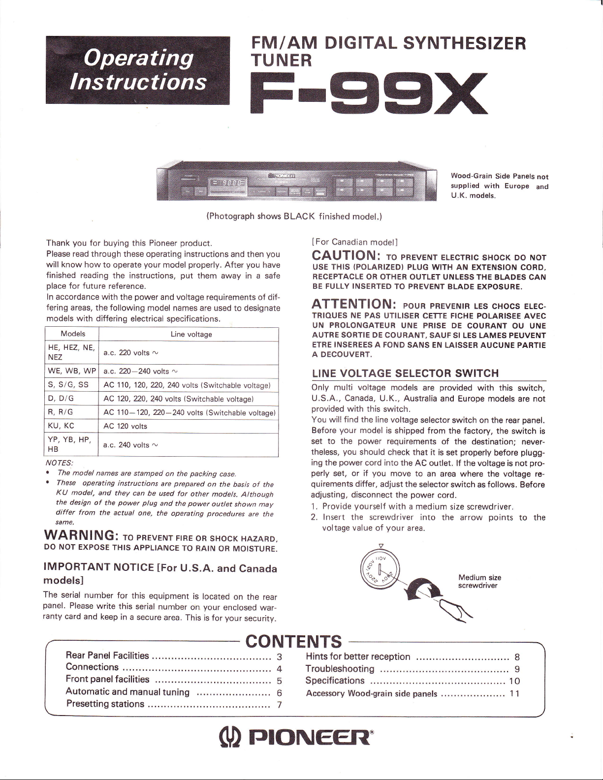
(Photograph
and then
properly.
voltage
volts
(Switchable
volts
packing
other
power
TO RAIN
After
them away in a safe
requirements of dif-
to designate
(Switchable
voltage)
(Switchable
case.
on the
basis of the
models.
Atthough
outlet
shown may
procedures
oR
sHocK HAZARD,
OR MOISTURE.
shows BLACK finished
IFor
you
you
have
CAUTION:
USE THIS
RECEPTACLE
BE FULLY
ATTENTION:
TRIOUES
UN
AUTRE SORTIE DE
ETRE
A DECOUVERT,
LINE
voltage)
voltage)
are the
Only
U.S.A., Canada,
provided
You will find the line voltage
Before
set to
theless,
ing
perly
quirements
adjusting,
1.
2. lnsert the screwdriver
model.)
Canadian
PROLONGATEUR
INSEREES
model]
(POLARIZED)
OR OTHER
INSERTED
NE
PAS
A FOND
VOLTAGE
multi voltage
with this
your
model
power
the
you
should check that
power
the
set, or if
Provide
voltage value of
cord into the
you
differ,
disconnect
yourself
Wood-Grain
supplied
U.K.
pREvENr
ro
PLUG WITH
OUTLET UNLESS THE BLADES
TO PREVENT
pouR
UTILISER CETTE FICHE
UNE PRISE DE
COURANT,
SANS EN
ELEcrRrc
AN EXTENSION CORD,
BLADE EXPOSURE.
pREVENTR
SAUF SI LES LAMES PEUVENT
LAISSER AUCUNE PARTIE
SELECTOR SWITCH
models
U.K., Australia
switch.
is
shipped from the
requirements
move to
adjust the
the
with a medium
provided
are
and Europe models
selector switch on the rear
of the
it is
set
AC outlet.
selector
power
lf the voltage is not
an area where the voltage re-
switch as follows. Before
cord.
size
into the
your
area.
0
Panels
Side
with Europe
models.
sHocK oo Nor
CAN
LEs cHocs ELEc-
POLARISEE AVEC
COURANT
with this
factory, the switch is
destination; never-
properly
arrow
before
screwdriver.
points
OU
switch,
are
panel.
plugg-
to the
UNE
pro-
not
and
not
IMPORTANT
modelsl
The
serial
panel.
ranty
number
Please
write
card
and
keep
Rear
Panel
Connections
panelfacilities
Front
Automatic
Presetting
NOTICE
for
this
this serial
in a
secure
Facilities
and
manual
stations
U.S.A.
[For
equipment
number
area. This
tuning
and
is located
your
on
is
for
(D
Canada
on the rear
enclosed
your
war-
security.
CONTENTS
Hints
3
Troubleshooting..........
4
Specifications .............
5
Accessory
6
7
rrloNEER'
for
better reception
Wood-grain
.............................
panels
side
.............. I
............
1
.... 11
8
O
Page 2
SAFETY
READ INSTRUCTIONS
operatihg instructions should be
appliance is operated.
RETAIN
INSTRUCTIONS - The
tions
should be
HEED
WARNING - All warnings
and in the
operdting
to.
FOLLOW
INSTRUCTIONS
inslructions
WATER AND MOISTURE The
not be
bathtub, washbowl, kitchen
wet basement, or near a swimming
LOCATION
stable location.
WALL
should not be mounted to a wall or
VENTILATION
that its location
its
should not be situated
similar surtace that may block the venlilation
ings;
bookcase
air through the ventilation
HEAT
heat sources
stoves,
that
POWER
nected
ed
appliance.
POWER-CORD
should be routed
walked
against
at
where they
POLARIZATION
vided
following
with a
having one blade wider
will lit into
satety
tully into
plug
to replace
sa{ety
CLEANING
with a
clean with furnature wax,
other volatile liquids
cabinel.
should be
used near
The appliance should be installed
-
OR CEILING MOUNTING - The
proper
ventilation. For example. the appliance
placed
or,
or cabinet that may impede the flow of
The appliance should be sitoated
or other appliances
produce
SOURCES
power
to a
in
the operating instructions or as marked
PROTECTION
on or
them,
plugs,
convenience receptacles,
exit
polarized power plug,
with a
instructions. This
polarized
the
feature.
the outlet,
should still fail
your
purpose
The
-
polishing
INSTRUCTIONS
All the safety and
retained for luture relerence.
instructions
All
-
followed.
water - for
sink,
The appliance should be
position
or
does not interfere with
bed, sota, rug,
on a
in a built-in installation, such as a
openings.
radiators,
such as
heat.
-
pinched
paying panicular
from
lf
-
alternating current line
power
you
lJ
obsolete outlet. Do not defeat
of the
appliance should be
cloth or a soft dry
(including
The appliance
supply only of the type describ-
Power-supply
-
so that they are not likely to be
by items
the appliance.
your purchased product
product
than the other). This
outlet only one way. This is a
unabie
are
reversing
try
fit,
to
contact
polarized
benzine, insecticides
since they may corrode the
read
before the
operating instruc-
on the appliance
should be adhered
operating and use
appliance should
example, near a
laundry
tub, in a
pool,
etc.
in a
appliance
ceiling.
situated so
open-
from
away
heat registers,
ampliliers)
should be con
on the
cords
placed
upon
attention
to cords
point
the
and
pro-
is
please
read
is
equ;pped
(a
plug
plug
plug
plug
inseft
to
the
plug.
the
lJ the
your
electrician
plug.
cleaned only
Never
cloth.
POWER
LINES
located
NONUSE PERIODS
pliance
left unused for a long
OBJECT AND LIOUID ENTRY
taken so that objects do not fall
spilled into the enclosure
DAMAGE REOUIRING
should
center
.
power-supply
The
damaged; or
.
Objects have
appliance;
the
.
The appliance has been
.
The appliance does
or exhibits
.
The appliance has been
damaged.
SERVICING
or
or
the
the
or
the appliance beyond
operating
tact the nearest Pioneer authorized setuice center.
CFOUND NG
ELECTROOE
re
nreoo'
mera wsrer
I
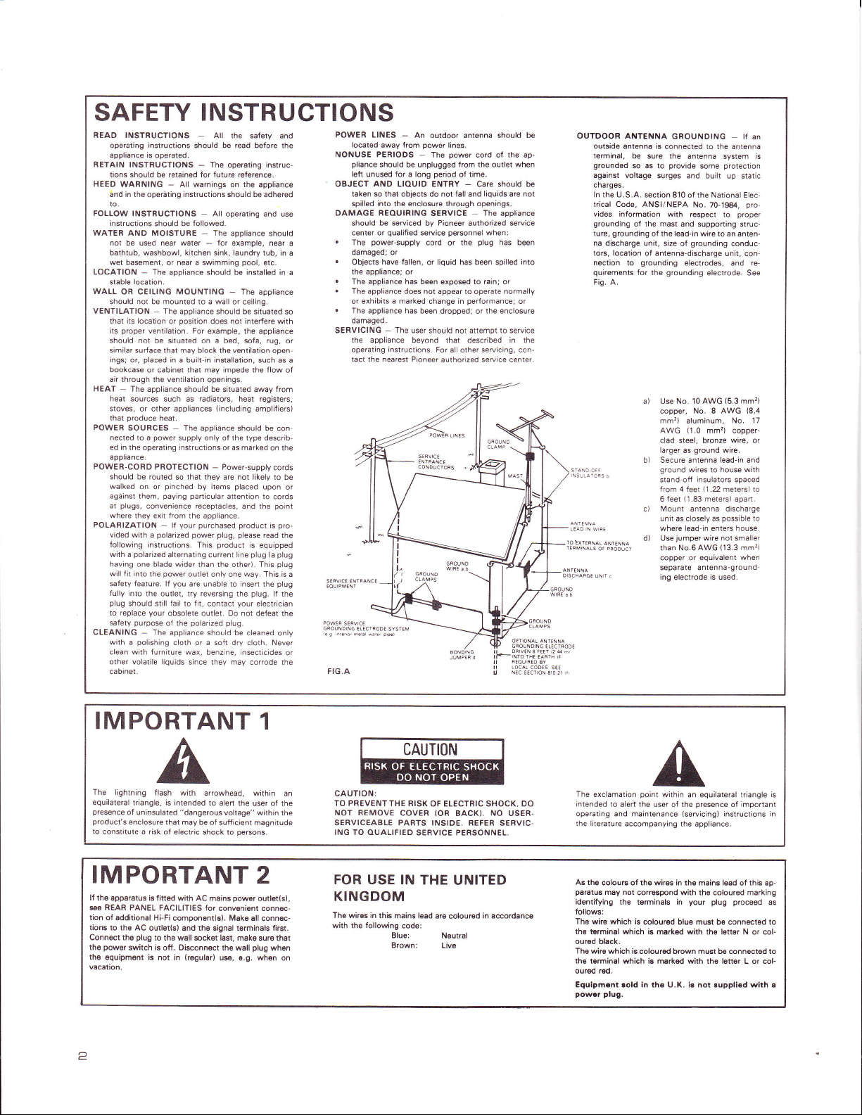
FIG.A
An outdoor antenna should be
-
power
away trom
should
be seruiced
qualified
or
lallen,
or
a marked
The user should
-
instruclions.
SYSI€M
orFl
lines.
The
be unplugged from
period
through
SERVICE
Pioneer
by
personnel
service
cord
or
or liquid has been spilled into
exposed
not appear to operate
change in
dropped; or
that
For
power
cord ot the ap-
the
of time.
Care should be
-
liquids are not
and
openings.
The
authorized setuice
when:
plug
the
to rain; or
performance;
the enclosure
attempt to seruice
not
described in the
seaicing,
all other
oullel
appliance
has been
normally
when
or
con-
OUTDOOR
ANTENNA
outside antenna is
lerminal,
be sure the
grounded
so as to
against voltage
charges.
ln
the U.S.A. section
trical Code, ANSI/NEPA
vides information with
grounding
of the mast and
grounding
ture,
na discharge unit,
tors, location
nection to
quirements
Fis. A.
of antenna-discharge unit,
grounding
lor
a) Use No.
b) Secure antenna lead-in and
ci
d) Use
GROUNDING
connected to the antenna
antenna system
provide
surges and built
ol the lead-in wi.e to an anten-
the
some
810 of the National Elec-
No.
respect to
supporting struc-
grounding
size of
electrodes,
grounding
10 AWG
copper, No,8
mm,)
aluminum,
(1.0
AWG
clad steel, bronze
larger
ground
as
ground
wires to
stand-off insulators spaced
from 4 {eet
(1.83
6 feet
Mount
antenna
unit as closely as
where lead in enters house.
jumper
AwG
than No.6
copper or equivalent
separate antenna-ground
ing
electrode
-
protection
up static
70-1S4,
proper
conduc
and
electrode. See
(5.3
AWG
No. 17
mm'?) copper-
wire,
wire.
house
(1.22
meters) to
meters) apaft.
discharge
possible
not
wire
smaller
(13.3
when
is used.
lf an
con
mm?)
with
mm'l)
is
pro-
re-
(8.4
or
to
IMPORTANT
The
lightning flash
equilateral triangle,
presence
of uninsulated
product's
enclosure
to constitute
with arrowhead,
is intended
"dangerous
that may be o{ sufficient
a risk
of electric shock to
to alen the user
IMPORTANT
lf the
apparatus is titted
e€ REAR PANEL
tion
of sdditional Hi-Fi
tions to the AC
Connect the
pow€r
the
th€
squipm€nt is not in
vacation.
2
switch is oft. Disconnect
with AC mains
FACILITIES for
component(s), Mako all connec-
outl€r(sl 8nd the signal terminals fi6t.
plug
to ths wsll
sck€t
(regulsr)
1
within
magnitude
persons.
of the
within the
voltage"
2
power
ourler(s),
conv€nisnt connec-
last,
make sure thal
plug
th€ wall
ue, a,g. whan
when
CAUTION
an
on
CAUTIONI
TO PREVENT THE NISK
NOT REMOVE
SERVICEABLE PARTS INSIDE, BEFER
ING TO OUALIFIED SERVICE PERSONNEL.
FOR USE IN
OF ELECTRIC SHOCK, DO
(OR
COVER
THE
BACK).
UNITED
NO
KINGDOM
The wires in this
with th€ lollowing code:
mains lead
Elue:
Brown:
are colour€d
N€utral
Live
in sccordance
USER.
SERVIC,
The
exclamation
intended
operating and maintenance
the literature
As the
paratus
id€ntifying
follows:
The wire which
th€ torminal which is marked with
oursd black.
The
wir€ which is coloursd brown must be connecled to
th€
tsrminal which is marked with the l€tter L or col-
ourd red,
Equipmcnt sold in tho U.K. is not
powrr
point
within an equilateral triangle is
to aleit rhe
accompanying the
colouE of the wires in the mains l€ad
may not
corraspond with the coloured marking
the tsrminals in
is colourod blue must be conntrted to
plug.
user of the
(seruicingi
presence
instructions in
appliance.
your plug proceed
l6nsr N
th€
euppliod
of important
of
this
or col-
wlth a
ap-
as
Page 3
REAR PANEL
FACILITIES
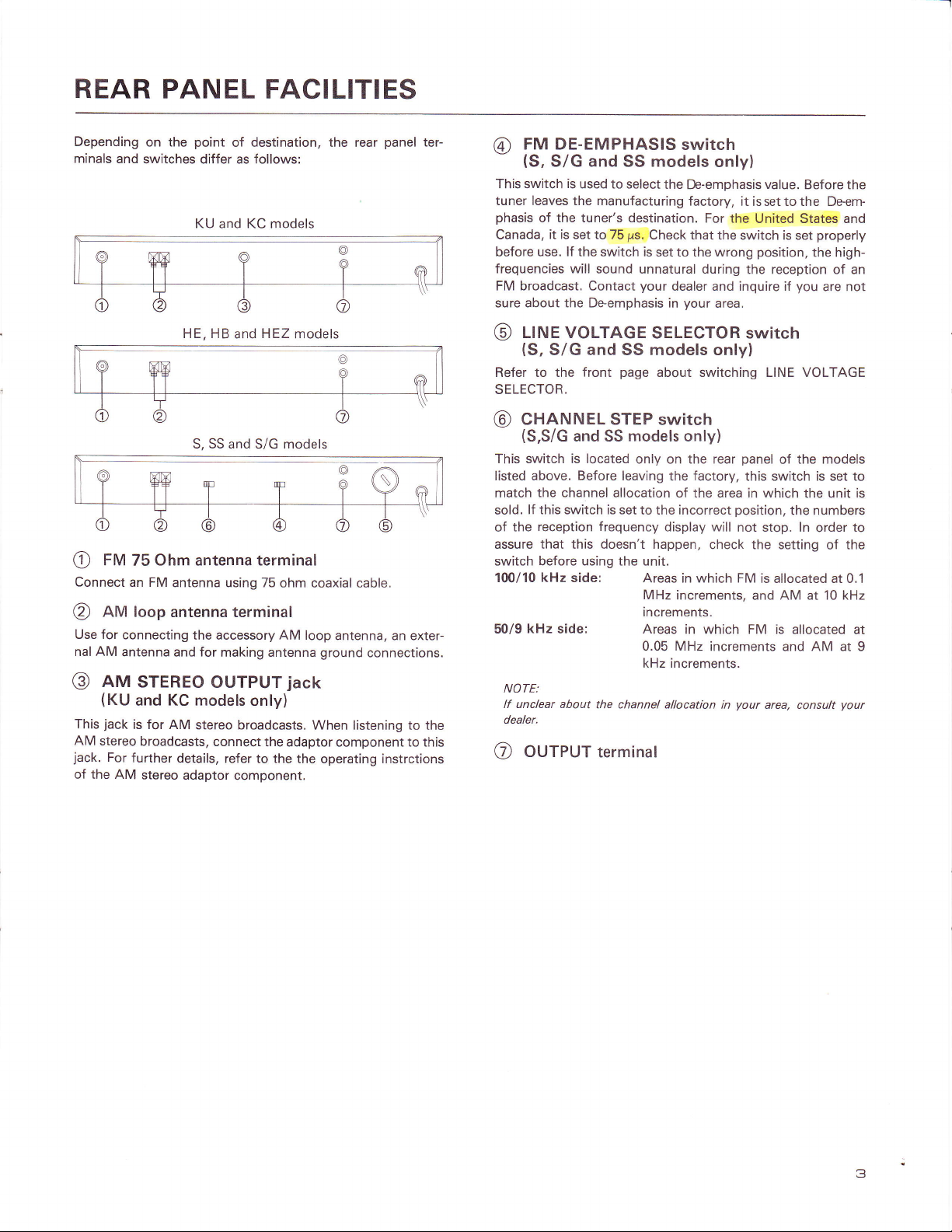
Depending
minals and
e
Connect
@
Use for
nal AM
@
This
AM
jack.
of the AM
on the
switches differ as follows:
FM
75
an FM
AfU loop antenna terminal
connecting
antenna and for
aru
STEREo
(KU
and
jack
is for AM
stereo
broadcasts,
For
further details,
stereo
point
KU and KC models
HE, HB
S, SS and S/G models
Ohm
antenna
antenna using 75
the accessory
ouTpUT
KC models
stereo
connect
adaptor
of destination, the rear
panel
andHEZ models
terminal
ohm coaxial cable.
AM
loop
antenna, an exter-
making antenna
ground
connections.
jack
only)
broadcasts. When listening to the
the adaptor component to this
refer to the
component.
the operating instrctions
ter-
FM DE-EMPHASIS
@
(S,
S/G and
This switch
tuner leaves the manufacturing
phasis
Canada,
before use. lf the switch is
frequencies will
FM broadcast.
sure about the Deemphasis in
@
Refer to the
SELECTOR.
@
This switch is located
listed above.
match
sold.
the
of
assure that this doesn't happen,
switch before using the unit.
100/10 kHz side:
50/9
NOTE:
lf unclear about
dealer.
@
is
of the tuner's destination.
it is set to 75
llrue voLTAGE
(S,
S/G and SS models only)
cHnruruEL STEP
(S,S/G
kHz
OUTPUT
and SS
the channel
lf this switch is
reception frequency
side: Areas
SS
used to select
ps.
sound unnatural during
Contact
page
front
models
Before
leaving
allocation of the area in which
set to the incorrect
the channel allocation in
terminal
switch
models
the
De-emphasis value. Before the
factory,
Check that
set to the wrong
your
dealer and inquire if
your
SELECToR switch
about switching LINE VOLTAGE
switch
only)
only on the rear
the
display will
Areas in which FM
MHz
increments, and AM
increments.
in which FM is
MHz
0.05
kHz increments.
only)
it is set to the Deem-
For the
factory,
United States and
the switch is set
position,
properly
the high-
the reception of an
you
area.
panel
this switch is set to
position,
not stop. ln
check the setting
the models
of
the
the numbers
order
is allocated at 0.1
at
allocated at
increments and AM at 9
your
area, consult
are not
unit is
the
of
10 kHz
your
to
3
Page 4
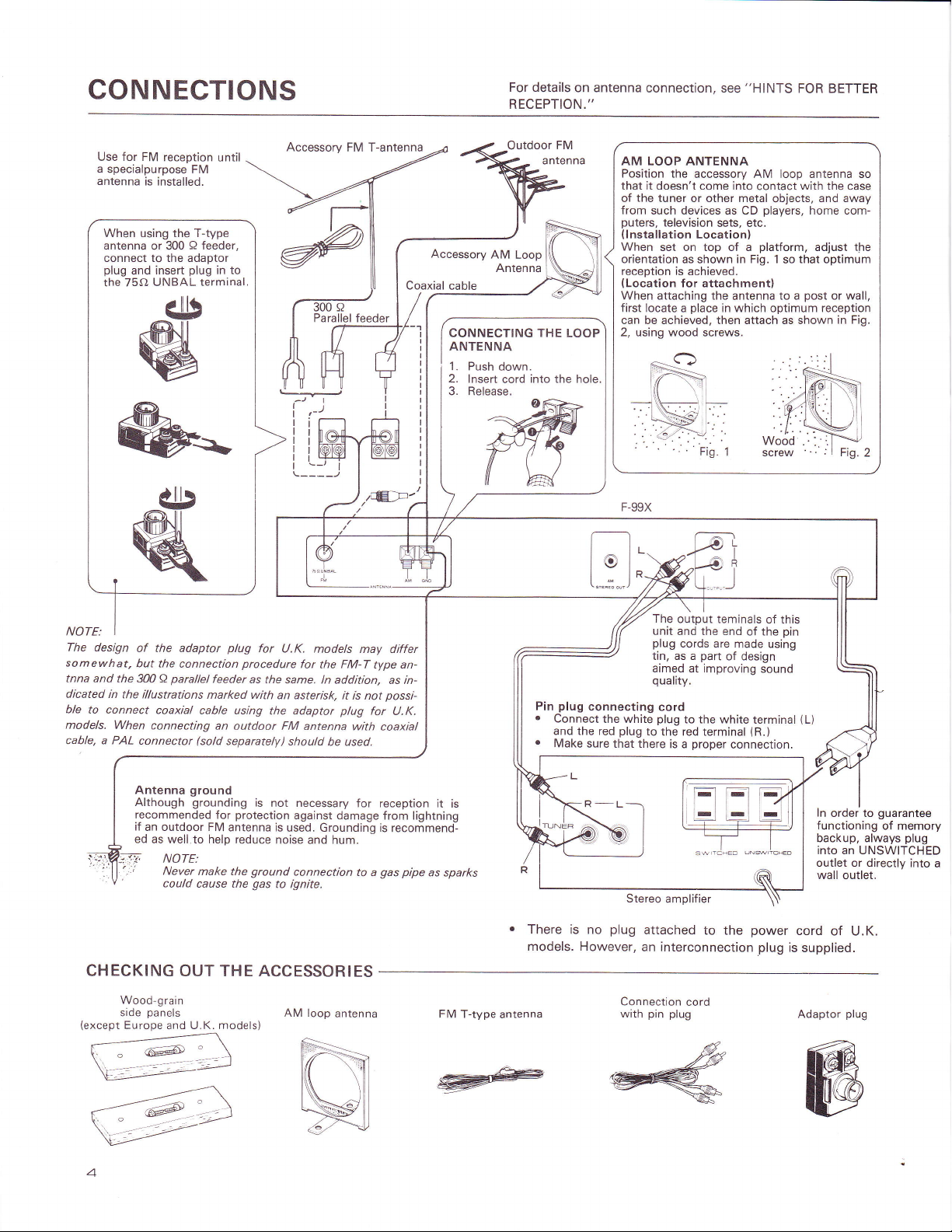
CONNECTIONS
For details
RECEPTION."
on antenna
connection, see
"HINTS
FOR BETTER
Use for FM
a
specialpurpose
antenna
When using the T-type
antenna
connect to the adaptor
plug
the 75O
reception
is installed.
Q
or 300
plug
insert
and
UNBAL terminal.
FM
until
feeder,
in to
Accessory
arallel
FM T-antenna
Coaxial cable
feeder
/E:F'
Accessory
AM
Loop
Antenna
CONNECTING THE
ANTENNA
1.
Push down.
2.
lnsert
cord
Reiease.
3.
LOOP
into the hole.
AM LOOP ANTENNA
Position the
that it doesn't come into
the
of
from
puters,
(lnstallation
When
orientation
reception is
(Location
When attaching the
first locate a
can be achieved, then attach as shown
2, using wood
accessory AM loop antenna so
tuner or other metal
such devices as CD
television
Location)
set on top of a
as shown
achieved.
for attachment)
place
screws.
Fig.
contact
players,
sets, etc.
platform,
in Fig. 1
antenna
in which optimum reception
1
HI
with the
objects,
that optimum
so
to a
case
and away
home com-
adjust the
post
or wall,
in Fig.
NOTE,
I
The design
somewhat,
tnna and
dicated
ble
models.
cable, a PAL
the 300 a
in
the illustrations
to connect
When
il,
t:,
CHECKING
Wood-grain
side
(except
Europe
of the adaptor
but the
connection
parallel
coaxial
connecting
connector
Antenna
Although
recommended
if
an outdoor FM
ed
as well.to help reduce
NOTE:
Never
could
plug
feeder
marked with
cable using
an
outdoor
(sold
separately)
ground
grounding
for
antenna is
make the
cause the
for
procedure
as the
is
protection
ground
gas
OUT THE ACCESSORIES
panels
U.K. models)
and
U.K.
models may differ
for
FM-T
the
same. ln addition,
an asterisk,
the adaptor
FM
should
not necessary
against damage
used. Grounding is
noise
connection
to ignite.
AM loop
it is not
plug
antenna
be used.
and hum.
antenna
type an-
as in-
possi-
for U.K.
with coaxial
for reception
from lightning
recommend-
pipe
gas
to
a
it is
as sparks
FM T-type
plug
Pin
.
Connect
and the red
.
Make
.
There is no
models. However,
antenna
The
unit
plug
tin, as a
aimed at improving
quality.
connecting
the white
plug
Stereo
plug
to
attached
sure that there
an interconnection
Connection
pin plug
with
output teminals
and the end
cords are
part
of design
cord
plug
to the white
the red terminal
proper
is a
amplifier
to the
cord
of
of the
made using
sound
terminal
(R.)
connection.
power
plug
this
pin
1L)
ln
order to
functioning
backup, always
into an UNSWITCHED
outlet or directly
wall outlet.
cord
of U.K.
is
supplied.
Adaptor
plug
guarantee
of memory
plug
into
a
@#<ffi
4
Page 5

FRONT
PANEL
FACILITIES
eOWeR
@
When
this
switch is set
dicator lights
circuits. The
transformer's
tion, the
connected
the
long
@
@
These
bands.
FM:
AM:
@
unit's
to
power
outlet when
period
of
POWER
fUruCflON
are
used to select
Push to
Push
to receive AM
Frequency
This shows
received
and the AM
@
in digital
SlCrunL
This indicates
antenna
elements
@
This
@
This lights
an FM
@
These
switch
quency
tion broadcasting
orientation.
light
rru
NARROW
light
to indicate FM
rru
STEREO
when
broadcast.
fUrulruG
are used
"("
to locate
and
the right half
switch
to
the
up, and
unit's POWER
secondary and so
power
power
circuitry will work
outlet. Disconnect the
you
time.
position,
ON
is
supplied to the tuner's
even at
long
as
plan
geared
switch is
do not
indicator
switches
either the FM
receive FM band broadcasts.
band broadcasts.
display
the frequency
form.The FM
band by kHz.
of the
station currently being
band is indicated
indicator
the
strength
etc.
up.
of the signal
so that a maximum
indicator
reception
in the
indicator
a stereo
program
has been
switch
to locate stations.
a station
of this switch
on a higher frequency.
Push
broadcasting
the
POWER in-
to
selecting
the
STAND-BY
power
as the
power
to
use the unit for
AM
or
broadcasting
received. Adjust
the indicator
of
narrow mode.
picked
the left half
on
a
")"
to locate
main
the
posi-
cord
from
cord
by MHz,
up during
of this
lower fre-
a sta-
vlnruunl
@
SEARcH/MUTE-oFF
switch/indicator
This switch is
For MANUAL
ing.
is
a
light. The MUTE function
the signal
is some
tion
AUTO
using
ing is recommended.
MUTING
Muting is incorporated
that can be heard when
It may not be
muting
the
station itself is
muting.
FM WIDE
@
This switch is used
tween WIDE
lights, and FM reception
FM WIDE:
FM NARROW:
sranoN
@
This
switch is
Mode 1
tained when
NOTE:
Changing
ance itself.
SfnflON
@
for
Use
preset
stations.
preset
to
used to
from
a station
distance
tuning. ln
possible
circuit is
distant. lf
Muting
switch/indicator
and NARROW.
MoDE
used
(1
8)
or Mode
-
the
switch
position
the
CALL switcheslindicators
presetting
These
a total of 16
select either AUTO
tuning.
press
the switch;
is
OFF during
is
comparatively weak,
away, reception
such
cases, the use
to eliminate FM
a
station is
to tune in
activated
does
not function
to change
if the signal
perform
so,
the FM reception
When
is
set to WIDE.
Permits
tion FM reception.
Use if interference
ing stations
reception.
switch/indicator
to set
the
STATION
(9
2
16).
-
pressed
is
of this
switch has
of desired stations
STATION
AM
CALL switches
FM
and
MANUAL
or
the indicator will
MANUAL
or if the sta-
may
not be
of MANUAL
inter-station
not tuned in
the desired
tuning without
for
AM reception.
pressed,
quality,
high
present
is
Mode 2
and the indicator
no effect
and for reception
stations.
is weak
from
CALL
(9
on tuner
accurately.
station when
the indicator
low distor-
during FM
switches
-
can be used
tun-
tuning.
possible
tun-
noise
or if the
using
mode
be-
neighbor-
16)
is
ob-
is
lit.
perform-
of
lf
to
UeUORY
@
This
is
used
depressed,
the frequency
switch
while
switch/indicator
to memorize
the
MEMORY indicator
of any station,
the MEMORY
stations.
press
indicator
When
will light.
the
STATION
is lighting
the switch is
To
memorize
CALL
up.
Page 6

AUTOMATIC AND MANUAL
TUNING
o
Check that all terminals are
switching on the unit.
o
Before
starting to use the unit,
on the stereo amplifier
AUTO
The
desired
SEARCH
electronic
station
Turn
on the
tuning
circuit inside
automatically.
POWER of the
properly
to TUNER.
stereo amplifier.
Select
your
desired
broadcasting band
using the FUNCTION switches.
Check
switch is OFF.
OFF.)
that the MANUAL SEARCH
(The
upper indicator
Press the TUNING switches
for
higher
a
lower frequency as
or
desired.
connected
turn the FUNCTION switch
the unit will
search for
before
your
unit and a
is
"<"
or
")"
MANUAL
TUNING
Turn on the POWER of
stereo amplifier.
Select
using
Press the MANUAL
3
(The
4 Use
frequency of
For step-by-step searching,
release
and
the TUNING switch
keep
up when
light
NOTE:
The SIGNAL indicator
distances or when signals
long
received in
your
desired
the FUNCTION switches.
upper
indicator
the TUNING switches
your
it immediately. For continuous
pressed.
the desired station is tuned
will not function for broadcasts
MANUAL TUNING, muting will not operate.
unit
the
broadcasting
SEARCH switch.
light
up.)
to locate
desired station.
press
the TUNING switch once
rapid scanning
The SIGNAL
in best.
are weak-
When
an
a
and
band
the
indicator
received over
FM broadcast is
will
The frequency will change rapidly
scanning. The
AUTO
SEARCH will stop
automatically when the desired station
located
light
up.
NOTE:
When
over long distances
manual
AUTO
the
tuning is
Caution with
o
o
.
this is a highly sensitive
Since
operation
ticularly
at
the search operation
cause
When using
search operation stops
the AM loop antenna
that only
the
for reception.
For very
stations.
powerful,
station,
weak stations, use
the
and
SEARCH
recommended.
SIGNAL
is in use, reception may not be
when
or
signals
Auto-Search:
mechanism, the frequency search
may stop even with
night. Also, frequency
Auto-Search to
be sure
to
stop.
preset
too frequently, changing
may be of help
nearby stations are
to reposition the antenna
the manual tuning
indicator will
are weak. At these times
weak foreign broadcasts,
noise in large cities
AM stations, if
in reducing its sensitivity so
received. After
the frequency
the
to its best
mode
during
possible
may
position
tuning in
position
preset
to
is
paralso
of
6
Page 7

PRESETTING
STATIONS
PRESETTING
1
Turn
on the POWER
a
stereo
2
Select band
3 Tune
r
See
tion
.
See
reception
4 Press
When
Not
in desired
the AUTO
using
Auto
the MANUAL
using
the
select
Mode
presetting
lit
amplifier.
of station
station.
SEARCH
Search.
SEARCH
Manual
STATION
1
or Mode
using
Mode
switch
section
Search.
1
STATION
to be
for
information
section
MODE
2.
of the unit and
memorized.
on recep-
for information
switch
CALL
switches
on
to
NOTE:
STATION
stations in
8 and AM
TION
CALL switches
any
stations
MODE
switch
RECEPTION
1 Turn
on the POWER
a
stereo
2 Press
which
(When
form
Tuning can be
the above
the desired
Station
procedure.
may be used
(2)
or
into I
acts as
preset
through
order,
USING
amplifier.
the
STATTON
necessary,
Mode
performed
simply
FM
16. ln
FIJNCTION
the
PRESET
switch
station
do
not
selection
and accurately
to
fl
)
stations
in
the second
switch as
TUNING
of the
CALL
has been
neglect
preset
FM
switches I
case,
well.
unit and
switch
preset.
to
as well.)
by following
and AM
through
the STA-
into
per-
presetting
When
Lit
I
*jJ.l:
L
{-
^<r
--?5ff1
v*l
Press
5 When
MEMORY
r
The
Memory
6 Press
is lit.
Memory
16
AM
contains
be entered
you
Press
and FM
which
.
Perforrn presetting
dicator
.
lf
the
possible.
presetting.
7
Repeat
switches
Up
to
you
lf
accidently
which
tion
will
using
station
switch.
indicator
the
STATION
wish
during
indicator
the Memory
steps
2
1
through 16.
stations
preset
a
information.
instead.
Mode
2
STATION
is
tuned
lights.
preset
to
the time
goes
to 6 to
may be
station into
it will
CALL
the
that
presetting
out,
switch
preset
memorized.
a
STATION
be erased
CALL
switches
press
in,
switch into
station.
the Memory
is
no longer
again
to
stations
CALL switch
and
the new
the
in-
perform
into
sta-
NOTES:
.
Preset
the POWER
cord is
.
lt is
cord
time.
function
that
to 3
.
lf a
Last
.
When
on,
previously
r
When
switch is
the
be received
stations
not
disconnected.
recommended
when
the unit
The
electrical
powere.d
is
the
unit will
days.
preset
station
station
the POWER
the last
FUNCTION
station received
turned
power
pressed,
again.
will
be retained
is switched
that
is not
circuit
by a BACK-|JP
preset
retain
has been
memory
switch
off will
is
ON. if
the last
switch
in
OFF as long
you
being used
the MEMORy
disconnect
for long
controlling
stations for
erased,
reset
pressed
is
before
be received
the FUNCTION
station
received
previously
was
when
pOWER
the
as
qOWER
the
periods
the
MEMORy
CONDENSER
period
a
to
the
again.
it.
power
turn
power
selector
before
pressed
of up
of
so
was
will
Page 8

HINTS FOR BETTER
RECEPTION
EXTERNAL
The main
broadcast
quality
of
purpose
multi-element
should
be used.
CONNECTIONS USING COAXIAL
As illustrated.
to the
supplied adaptor
ing
of the cable does not contact the inside filament. Then,
sert the
A-UNBAL).
CONNECTIONS
FM ANTENNA
advantage of FM
signal. ln
FM
broadcasts, it is recommended"that
FM
antenna be
(3
prepare
adaptor
to
oder
installed.
element, 5 element,
the
ends of
plug.
plug
into
AM is the
over
fully
benefit
ln weak signal areas, a
the
coaxial cable and
Take
care that the outside
the antenna
USING 3OO
quality
from the high signal
7
element) antenna
CABLE
input
terminal
A
PARALLEL
FEEDER
Prepare
tor
as short as
metal
lnsert the
A-UNBAL).
EXTERNAL
lf it is not
changing the
indoor
INDOOR
Use a
AM
ing,
OUTDOOR
lf reception
indoor
outside and fixed in
the ends
plug
as shown
possible
objects, coiling
adaptor
AM ANTENNA
possible
orientation of
antenna, or an outdoor antenna should be installed.
AM ANTENNA
vinyl
coated wire
antenna terminal and affix the
as high
antenna is used, a vinyl
NOTE:
Do not detach
door AM antenna-
possible.
as
AM ANTENNA
quality
the AM loop antenna when using
parallel
the
of
in the illustration
and
it,
plug
to obtain adequante AM reception even by
(5
is
not
place.
feeder and attach to the adap-
page
on
avoid letting it
piling
or
into
-
improved
excess length on the
the antenna input terminal
the AM loop
6 m) and
other end to the
coated
4. Keep
into
come
antenna, a separate
connect one end
sufficiently
wire
should be
an
contact
even
indoor
of the
a special-
attach
webb-
length
the
wall
or ceil-
when an
installed
an
or
in-
(75
with
floor.
(75
to the
out-
FM outdoor antenna
o
l.Prepare
2.Attach
External AM antenna connections
KU, KC,
When
coaxial cable as illustrated below.
.
strip off
to expose the core.
(except
the
HB
Press
the
outer
prepared
model)
S, SS and
casing
cable to the
S/G
models.
(except
',tJ':od*J1fir"::?:""XTt
fold 6ack the
or
adaptor
plug provided.
{frq
Be sure to
remove
this
pin
when
usrng
coaxial
cable.
,":rffi
inner core.
HB
model)
webbing.
T,:?T"lii,l?1"'
l-K tnis stit.
ilrt
"Ns
Orient the
optimum
loop antenna
reception.
for
Page 9

TROU
BLESHOOTING
you
lf
tion
used
nearest authorized Pioneer
your
think
is to
as well
unit is malfunctioning.
blame. Alternatively,
as any other
Symptom
(POWER
power
No
switch
at
ON)
No
sound
Static
Sound
distortion
Stereo
received
broadcasts
in stereo.
not
take
the time to check
may lie outside
the
problem
electrical appliances.
service
station.
.
r
e
connection loose?
.
days?
.
ls the
frequencV?
.
Has
connection loose?
On the FM band
.
ls
and not
the
.
Are the
.
Static from other
automobiles)
(radio
buildings
On the AM band
o
Poor
.
ls
with tuner?
.
Are the
.
Static Jrom
(fluorescent
a
Are
a
ls the
power
Has the
Have
any of the
nected
or incorrectly
Has the
antenna been disconnected
power
Has
the
(Station
properly
station
the antenna
the
cord of the
extended or is the
wrong direction?
signals weak
or multipath reflection
waves
beamed off mountains
not
and
positioning
accessory AM loop
signals weak
other electrical appliances
lights
the signals
frequency
out the
the
unit. Make a
lf the trouble
is not
Trouble
cord been disconnected?
output cords been
connected?
switch been left
memory has
tuned in
disconnected
been
T-antenna
antenna facing in
and reception
appliances
received directly.)
of AM loop
antenna in
reception
and
/motors)
weak, with insufficient
tuned in
properly?
discon-
or
o{f for several
been lost.)
to the
or is the
still folded up
poor?
(particularly
and tall
antenna?
contact
poor?
points
below. ln
point
remedied even
is
the
correct
?
input?
of
checking
after checking
.
Reconnect
.
Connect them
minals
.
connect the
o
Reprogram
o
Tune
.
Connect
.
Extend the
change the
reception
.
Substitute
FM
T-antenna.
.
Try varying
antenna
substituting
standard
possible
.
Change the
best
.
Separate
tuner.
o
Fix
an
antenna.
Switch off
away.as
a
Change to
antenna
a
Tune
many cases.
the other
power
the
properly
on the
amplifier.
antenna
station memory
in the
station correctly.
the antenna
two ends
direction
is
obtained.
an FM
the
height and
or use
an
a 75-ohm
cable
and fixing it
from
the street.
direction
reception is
loop
antenna as far
AM
outdoor
other appliances
possible
a multi-element
in station
accurately.
carelessness
or incorrect
stereo components
points
the
Remedy
properly.
properly.
of the antenna and/or
of the
outdoor antenna for
FM
of
obtained.
antenna
from
below,
cord
to the
TUNER ter-
antenna until best
direction
outdoor
coaxial cable for
antenna
as far away
the
antenna
possible
as
ground
or
or keep
the tuner when in
outdoor FM
contact
the
the
of
the
until
the
as far
opera-
being
your
as
from
use.
I
Page 10

SPECIFICATION
FM Tuner
Frequency
(except
(SandS/G
Usable
NARROW
50dB
NAR
50dB
NARROW.
Sensitivity
NAR ROW
Signal-to-Noise
Section
range
and
S
Sensitivity
Ouieting
ROW
Ouieting
(D
models)
S/G
87.5MHz
models)
.... ..
10,8d8f,
Sensitivity
,
.
Mono; 12.8dBf, lH
Stereo;34.8
Sensitivity
.
Mono; 15.3dBf, IHF
(KU
dBf, IHF
(except
Stereo;35.9d8f,
lN)
Mono; o]5
Ratio . . . .
Mono; 94dB
SSMHzto
IHF
model)
IHF
Stereo;
Stereo;87dB
(DlN)
Signal-to-Noise
Distortion
WIDE ...
R ROW
NA
CaptureRatio.
Alternate Channel Selectivity
NARROW
Stereo Separation
WIDE
Frequency
Ratio
(at
80dBf
)
Response
Mono;0.015%(100H2)
Stereo;
Mono; 0.09%
Stereo;
....0.8d8(WIDE)
.....BbdB(400kHz)
....65d8(1kHz)
55dB
(20H2
dB
]3.3
lmageResponseRatio .
F Response Ratio
I
AMSuppressionRatio
SpuriousResponseRatio.
SubcarrierProductRatio.
Muting
Antenna lnput .
Threshold .
. . 25.2d9f
to 108MHz
108MHz
(0.95
pvlTSAl
(1
F
.2
l75A)
ttY
(15
pVl75O)
KU model) . , . .
(1.6
pVl75O)
(17
pYl75A].
pY
l75d}
pVl75{L
20
(at
80dBf)
(at
80dBf)
Mono;76dB
Stereo; 73dB
0.0095%
0.O2%
O.O2Y.
O.O2%o
O.O7%
(20H2
(1kHz)
(6kHz)
(100H2)
(1
(1OkHz)
0.5%
to 10kHz)
15kHz)
to
(1
(1
kHz)
kHz)
kHz)
....70dB
100d8
.
..,..70dB
..80dB
...60dB
(5
s.V/754)
unbalanced
75O
Tuner
AM
Frequency
Sensitivity
Section
range
(except
(HB
model)
(l
H F, Loop antenna) 150
model). .530kHz
HB
531kHz
1
to
600kHz
to 1602kHz
pVlm
Selectivity .,..18dB
Signal-to-NoiseRatio
lmageResponseRatio.
Response Ratio
lF
Antenna
Audio Section
(
Output
Miscellaneous
Power
Level/
(100%
FM
(30%
AM
Requirements
model
HE
model
HB
KU and
and
S, SS
AC
mpedance)
I
MOD)
MOD)
KC models
S/G
1 1 Ol12Ol22Ol240V
FIXED
FIXED
. . . a,c.
. . a.c. 240
.
models
220Volts
. . . .
(switchable)
PowerConsumption....
......50d8
....40d8
LoopAntenna
..,
650mV/900o
150mV/900O
-,
Volts
-,
AC 120V,
. . 60dB
50/60H2
50/60H2
60Hz
50/60H2
20W
' '
'.
o'":]:l'':l*::
12-5l16
(9lb
15oz)
1oz)
mm
mm
. 1
:::*:#di:
(only
Dimensions
Weight
(without package)
Except
Europe and
Only
Furnished
FM
T-type
Loop Antenna
AM
Connection
AdaptorPlug.
Wood-Grain
Operati
ng I
Europe and
Europe
and U.K.
Parts
Antenna
Cord
Side
nstructio
;.:ffJi
x
U.K.
models
2-1
l2(Hl
models)
x 63.5(H)
x2-112(H\
.
. . .
Europe and
18(W)
420(W)
16-9/16(W)
modles
U.K.
Pin Plugs . . .. . .
with
Panel(except
ns
x
312(D)
x
12'5116(D)in
x 312(D)
x
4.5kg
4.1k9(9lb
........'l
U.K.models)
in
1
1
2
1
NOTE:
Specifications
without
notice.
design subiect
and
possible
to
modification
Page 11

ACCESSORY
panels
Side
When
items:
o
Use
stallation.
.
Do
o
When
the
lnsta
(1)
Use
(two
made
and
Using
l2l
moved,
the accessory
the
(3)
There
wood-grain
When tightening,
tioned
NOTE:
Avoid
wo od-
not supplied with Europe
the
not remove
side
panels
side
only the screws
any screws
repacking
panels
this unit
first.
are used,
accompanying
llation
your
fingernail,
on each side)
of the
(B)
together.
the holes from which
attach the wood-grain
wood-grain
is a
certain amount
side
evenly with respect
overtightening
g
ra in
side
panels.
etc., to remove the four
on the sides of the unit. The rivets
(A)
pair
screws.
pattern
panels
make
as this may damage
and
Be sure to install
WOOD.GRAIN
and U.K.
please
abide by the following
the side
attached to this
(for
storage or shipment), remove
(B);
be sure to remove
plastic
the
panels
side
is
on the
outside.
play
of
in the
before
they are tigfrtened
sure that
they are flush and
to the front
the
models.
panels
unit.
plastic
both
rivets were re-
to the unit with
panels
the
position
panel
and cabinet.
cabinet and the
for
rivets
so that
of the
down.
posi-
SIDE PANELS
Wood-grain
panel
side
-
in-
are
(A)
6-
4
(B)
Front
panel
={
(A)
Screw
Wood-grain
panel
side
il
Page 12

-fif
PICINEEFI
PICINEEFI
PIONEEFI
PIC,NEEFI
<
85HOOY7DO7
ELECTFICINIC CCIFIPCIFIATICIN 4-1,
ELECTIICINICA
ELECTFIGINIC
ELECTFIGINICA
lNc, P.O. Box
IUCiAI
IEUFICIPEI
AUATHALIA PTY. LTEI.
TEL:
N.V. Keetbengla6n 1,2740
[AOo]
1760,
421-1404,
174-l84
Long Beech, Celifonnia 9OAOI U.S.A.
Meguno 1-chome, Mesuno-ku, Tokyo 153,
237-O4?4
IEOOI
Bevenen,
Boundany
Belgium TEL: 03/775.2El.0E}
Flosd,
Bnereside, Victonia 3195, Austnalia
Japan
 Loading...