

Page 1
DJ EFFECTOR
BOÎTE D’EFFETS DJ
DJ-EFFEKTGERÄT
REALIZZATORE DI EFFETTI DJ
DJ-EFFECTOR
UNIDAD DE EFECTOS PARA DJ
EFX-1000
Operating Instructions
Mode d’emploi
Bedienungsanleitung
Istruzioni per l’uso
Gebruiksaanwijzing
Manual de instrucciones
Page 2
IMPORTANT
CAUTION
RISK OF ELECTRIC SHOCK
DO NOT OPEN
The lightning flash with arrowhead symbol,
within an equilateral triangle, is intended to
alert the user to the presence of uninsulated
"dangerous voltage" within the product's
enclosure that may be of sufficient
magnitude to constitute a risk of electric
shock to persons.
CAUTION:
TO PREVENT THE RISK OF ELECTRIC
SHOCK, DO NOT REMOVE COVER (OR
BACK). NO USER-SERVICEABLE PARTS
INSIDE. REFER SERVICING TO QUALIFIED
SERVICE PERSONNEL.
The exclamation point within an equilateral
triangle is intended to alert the user to the
presence of important operating and
maintenance (servicing) instructions in the
literature accompanying the appliance.
D3-4-2-1-1_En-A
IMPORTANT
ATTENTION
DANGER D´ELECTROCUTION
NE PAS OUVRIR
Ce symbole de l’éclair, placé dans un
triangle équilatéral, a pour but d’attirer
l’attention de l’utilisateur sur la présence, à
l’intérieur du coffret de l’appareil, de
“tensions dangereuses” non isolées d’une
grandeur suffisante pour représenter un
risque d’électrocution pour les êtres
humains.
ATTENTION:
POUR ÉVITER TOUT RISQUE
D’ÉLECTROCUTION, NE PAS ENLEVER LE
COUVERCLE (NI LE PANNEAU ARRIÈRE).
AUCUNE PIÈCE RÉPARABLE PAR
L’UTILISATEUR NE SE TROUVE À
L’INTÉRIEUR. CONFIER TOUT ENTRETIEN À
UN PERSONNEL QUALIFIÉ UNIQUEMENT.
Ce point d’exclamation, placé dans un
triangle équilatéral, a pour but d’attirer
l’attention de l’utilisateur sur la présence,
dans les documents qui accompagnent
l’appareil, d’explications importantes du
point de vue de l’exploitation ou de
l’entretien.
D3-4-2-1-1_Fr
WICHTIG
CAUTION
RISK OF ELECTRIC SHOCK
DO NOT OPEN
Das Blitzsymbol in einem Dreieck weist den
Benutzer darauf hin, dass eine
Berührungsgefahr mit nicht isolierten Teilen
im Geräteinneren, die eine gefährliche
Spannung führen, besteht. Die Spannung
kann so hoch sein, dass sie die Gefahr eines
elektrischen Schlages birgt.
ACHTUNG:
UM SICH NICHT DER GEFAHR EINES
ELEKTRISCHEN SCHLAGES AUSZUSETZEN,
DÜRFEN SIE NICHT DEN DECKEL (ODER
DIE RÜCKSEITE) ENTFERNEN. IM
GERÄTEINNEREN BEFINDEN SICH KEINE
VOM BENUTZER REPARIERBAREN TEILE.
ÜBERLASSEN SIE REPARATUREN DEM
QUALIFIZIERTEN KUNDENDIENST.
Ein Ausrufezeichen in einem Dreieck weist
den Benutzer auf wichtige Bedienungs- und
Wartungsanweisungen in den Dokumenten
hin, die dem Gerät beiliegen.
D3-4-2-1-1_Ge
IMPORTANTE
CAUTION
RISK OF ELECTRIC SHOCK
DO NOT OPEN
Il simbolo del lampo con terminale a forma
di freccia situato all’interno di un triangolo
equilatero serve ad avvisare l’utilizzatore
della presenza di una “tensione pericolosa”
non isolata nella struttura del prodotto che
potrebbe essere di un’intensità tale da
provocare scosse elettriche all’utilizzatore.
ATTENZIONE:
PER EVITARE IL RISCHIO DI SCOSSE
ELETTRICHE, NON RIMUOVERE IL
COPERCHIO (O IL RETRO). NON CI SONO
PARTI INTERNE LA CUI MANUTENZIONE
POSSA ESSERE EFFETTUATA
DALL’UTENTE. IN CASO DI NECESSITÀ,
RIVOLGERSI ESCLUSIVAMENTE A
PERSONALE DI SERVIZIO QUALIFICATO.
Il punto esclamativo in un triangolo
equilatero serve ad avvisare l’utilizzatore
della presenza di importanti istruzioni di
funzionamento e manutenzione riportate nel
libretto allegato al prodotto.
D3-4-2-1-1_It
BELANGRIJK
CAUTION
RISK OF ELECTRIC SHOCK
DO NOT OPEN
De lichtflash met pijlpuntsymbool in een
gelijkzijdige driehoek is bedoeld om de
aandacht van de gebruikers te trekken op
een niet geïsoleerde “gevaarlijke spanning”
in het toestel, welke voldoende kan zijn om
bij aanraking een elektrische shock te
veroorzaken.
WAARSCHUWING:
OM HET GEVAAR VOOR EEN ELEKTRISCHE
SHOCK TE VOORKOMEN, DEKSEL (OF RUG)
NIET VERWIJDEREN. AAN DE BINNENZIJDE
BEVINDEN ZICH GEEN ELEMENTEN DIE
DOOR DE GEBRUIKER KUNNEN BEDIEND
WORDEN. ENKEL DOOR GEKWALIFICEERD
PERSONEEL TE BEDIENEN.
Het uitroepteken in een gelijkzijdige
driehoek is bedoeld om de aandacht van de
gebruiker te trekken op de aanwezigheid van
belangrijke bedienings- en
onderhoudsinstructies in de handleiding bij
dit toestel.
D3-4-2-1-1_Du
IMPORTANTE
CAUTION
RISK OF ELECTRIC SHOCK
DO NOT OPEN
La luz intermitente com el símbolo de punta
de flecha dentro un triángulo equilátero.
Está convenido para avisar el usuario de la
presencia de “voltaje peligrosa” no aislada
dentro el producto que podría constituir un
peligro de choque eléctrico para las
personas.
Replacement and mounting of an AC plug on the power supply cord of this unit should be performed only by qualified
service personnel.
IMPORTANT
FOR USE IN THE UNITED
KINGDOM
The wires in this mains lead are coloured in
accordance with the following code:
Blue : Neutral
Brown : Live
If the plug provided is unsuitable for your socket
outlets, the plug must be cut off and a suitable plug
fitted.
ATE NCI ÓN:
PARA PREVENIR EL PELIGRO DE CHOQUE
ELÉCTRICO NO REMOVER LA TAPA NI LAS
PARTES DENTRO NO UTILIZADAS,
LLAMAR UNA PERSONA CUALIFICADA
The cut-off plug should be disposed of and must
not be inserted into any 13 amp socket as this can
result in electric shock. The plug or adaptor or the
distribution panel should be provided with 5 A fuse.
As the colours of the wires in the mains lead of this
appliance may not correspond with coloured
markings identifying the terminals in your plug,
proceed as follows ;
The wire which is coloured blue must be connected
to the terminal which is marked with the letter N or
coloured black.
The wire which is coloured brown must be
connected to the terminal which is marked with the
letter L or coloured red.
2
<DRB1368>
El punto exclamativo dentro un triángulo
equilátero convenido para avisar el usuário
de la presencia de importantes instruciones
sobre el funcionamento y la manutención
en la libreta que acompaña el aparato.
D3-4-2-1-1_Sp
Do not connect either wire to the earth terminal of a
three pin plug.
NOTE
After replacing or changing a fuse, the fuse cover in
the plug must be replaced with a fuse cover which
corresponds to the colour of the insert in the base
of the plug or the word that is embossed on the
base of the plug, and the appliance must not be
used without a fuse cover. If lost replacement fuse
covers can be obtained from your dealer.
Only 5 A fuses approved by B.S.I or A.S.T.A to
B.S.1362 should be used.
D3-4-2-1-2-2_En
WARNING
This equipment is not waterproof. To prevent a fire
or shock hazard, do not place any container filed
with liquid near this equipment (such as a vase or
flower pot) or expose it to dripping, splashing, rain
or moisture.
AVERTISSEMENT
Cet appareil n’est pas étanche. Pour éviter les
risques d’incendie et de décharge électrique, ne
placez près de lui un récipient rempli d’eau, tel
qu’un vase ou un pot de fleurs, et ne l’exposez pas
à des gouttes d’eau, des éclaboussures, de la pluie
ou de l’humidité.
WARNUNG
Dieses Gerät ist nicht wasserdicht. Zur Vermeidung
der Gefahr von Brand und Stromschlag keine
Behälter mit Flüssigkeiten (z.B. Blumenvasen und
-töpfe) in die Nähe des Gerätes bringen und dieses
vor Tropfwasser, Spritzwasser, Regen und Nässe
schützen.
ATTENZIONE
Questo apparecchio non è impermeabile. Per
prevenire pericoli di incendi o folgorazioni, non
posizionare nelle vicinanze di questo apparecchio
contenitori pieni di liquidi (quali vasi da fiori, o
simili), e non esporre l’apparecchio a sgocciolii,
schizzi, pioggia o umidità.
WAARSCHUWING
Dit apparaat is niet waterdicht. Om brand of een
elektrische schok te voorkomen, mag u geen
voorwerp dat vloeistof bevat in de buurt van het
apparaat zetten (bijvoorbeeld een bloemenvaas) of
het apparaat op andere wijze blootstellen aan
waterdruppels, opspattend water, regen of vocht.
ADVERTENCIA
Este aparato no es impermeable. Para evitar el
riesgo de incendio y de descargas eléctricas, no
ponga ningún recipiente lleno de líquido (como
pueda ser un vaso o un florero) cerca del aparato ni
lo exponga a goteo, salpicaduras, lluvia o
humedad.
WARNING
Before plugging in for the first time, read the following
section carefully.
The voltage of the available power supply differs
according to country or region. Be sure that the
power supply voltage of the area where this unit
will be used meets the required voltage (e.g., 230V
or 120V) written on the rear panel.
AVERTISSEMENT
Avant de brancher l’appareil pour la première, lisez
attentivement la section suivante.
La tension de l’alimentation électrique disponible
varie selon le pays ou la région. Assurez-vous que
la tension du secteur de la région où l’appareil sera
utilisé correspond à la tension requise (par ex. 230
V ou 120 V), indiquée sur le panneau arrière.
D3-4-2-1-4_A_Fr
WARNUNG
Vor dem erstmaligen Anschluss des Gerätes an das
Stromnetz bitte den folgenden Hinweis sorgfältig
beachten.
Die Netzspannung ist je nach Land verschieden. Vor
der Inbetriebnahme des Gerätes sicherstellen, dass
die örtliche Netzspannung mit der auf dem
Typenschild an der Rückwand des Gerätes
angegebenen Nennspannung (z.B. 230 V oder 120 V)
übereinstimmt.
ATTENZIONE
Prima di collegare per la prima volta l’apparecchio alla
sorgente di alimentazione leggere attentamente la
sezione che segue.
La tensione della sorgente di elettricità differisce
da Paese a Paese e da regione a regione. Verificare
che la tensione di rete della zona in cui si intende
utilizzare l’apparecchio sia quella corretta, come
indicato sul pannello posteriore dell’apparecchio
stesso (ad es.: 230 V o 120 V).
WAARSCHUWING
Lees zorgvuldig de volgende informatie voordat u de
stekker de eerste maal in het stopcontact steekt.
De bedrijfsspanning van het apparaat verschilt
afhankelijk van het land waar het apparaat wordt
verkocht. Zorg dat de netspanning in het land waar
het apparaat wordt gebruikt overeenkomt met de
bedrijfsspanning (bijv. 230 V of 120 V) aangegeven
op de achterkant van het apparaat.
ADVERTENCIA
Antes de enchufar el aparato a la corriente, lea la
sección siguiente con mucha atención.
La tensión de la red eléctrica es distinta según el
país o región. Asegúrese de que la tensión de la
alimentación de la localidad donde se proponga
utilizar este aparato corresponda a la tensión
necesaria (es decir, 230 V ó 120 V) indicada en el
panel posterior.
D3-4-2-1-3_A_En
D3-4-2-1-3_A_Fr
D3-4-2-1-3_A_Ge
D3-4-2-1-3_A_It
D3-4-2-1-3_A_Du
D3-4-2-1-3_A_Sp
D3-4-2-1-4_A_En
D3-4-2-1-4_A_Ge
D3-4-2-1-4_A_It
D3-4-2-1-4_A_Du
D3-4-2-1-4_A_Sp
Page 3
j
If the AC plug of this unit does not match the AC
outlet you want to use, the plug must be removed
and appropriate one fitted. Replacement and
mounting of an AC plug on the power supply cord of
this unit should be performed only by qualified
service personnel. If connected to an AC outlet, the
cut-off plug can cause severe electrical shock. Make
sure it is properly disposed of after removal.
The equipment should be disconnected by removing
the mains plug from the wall socket when left
unused for a long period of time (for example, when
on vacation).
Si la fiche d’alimentation secteur de cet appareil ne
convient pas à la prise secteur à utiliser, la fiche doit
être remplacée par une appropriée.
Ce remplacement et la fixation d’une fiche secteur
sur le cordon d’alimentation de cet appareil doivent
être effectués par un personnel de service qualifié.
En cas de branchement sur une prise secteur, la
fiche de coupure peut provoquer une sérieuse
décharge électrique. Assurez-vous qu’elle est
éliminée correctement après sa dépose.
L’appareil doit être déconnecté en débranchant sa
fiche secteur au niveau de la prise murale si vous
prévoyez une période prolongée de non utilisation
(par exemple avant un départ en vacances).
Falls der Netzstecker des Netzkabels dieses Gerätes
nicht in die Zusatzsteckdose einer anderen
Komponente passt, muss er gegen einen
Netzstecker der geeigneten Ausführung
ausgewechselt werden. Ein derartiger Austausch des
Netzsteckers muss vom Kundendienstpersonal
vorgenommen werden. Wenn der vom Netzkabel
abgeschnittene ursprüngliche Netzstecker in eine
Netzsteckdose eingesteckt wird, besteht akute
Stromschlaggefahr! Daher ist unbedingt dafür zu
sorgen, dass der abgeschnittene Netzstecker sofort
vorschriftsmäßig entsorgt wird.
Vor einem längeren Nichtgebrauch des Gerätes,
beispielsweise während des Urlaubs, sollte der
Netzstecker aus der Netzsteckdose gezogen werden,
um das Gerät vollständig vom Netz zu trennen.
Se la spina del cavo di alimentazione di questo
apparecchio non si adatta alla presa di corrente
alternata di rete nella quale si intende inserire la
spina stessa, questa deve essere sostituita con una
adatta allo scopo. La sostituzione della spina del
cavo di alimentazione deve essere effettuata
solamente da personale di servizio qualificato. Dopo
la sostituzione, la vecchia spina, tagliata dal cavo di
alimentazione, deve essere adeguatamente
eliminata per evitare possibili scosse o folgorazioni
dovute all’accidentale inserimento della spina stessa
in una presa di corrente sotto tensione.
Se si pensa di non utilizzare l’apparecchio per un
relativamente lungo periodo di tempo (ad esempio,
durante una vacanza), staccare la spina del cavo di
alimentazione dalla presa di corrente alternata di
rete.
Als de netstekker van dit apparaat niet geschikt is
voor het stopcontact dat u wilt gebruiken, moet u de
stekker verwijderen en een geschikte stekker
aanbrengen. Laat het vervangen en aanbrengen van
een nieuwe netstekker over aan vakkundig
onderhoudspersoneel. Als de verwijderde stekker
per ongeluk in een stopcontact zou worden
gestoken, kan dit resulteren in een ernstige
elektrische schok. Zorg er daarom voor dat de oude
stekker na het verwijderen op de juiste wijze wordt
weggegooid.
Haal de stekker van het netsnoer uit het stopcontact
wanneer u het apparaat geruime tijd niet denkt te
gebruiken (bijv. wanneer u op vakantie gaat).
Si la clavija del cable de alimentación de CA de este
aparato no se adapta a la toma de corriente de CA
que usted desea utilizar, deberá cambiar la clavija
por otra que se adapte apropiadamente. El
reemplazo y montaje de una clavija del cable de
alimentación de CA sólo deberá realizarlos personal
de servicio técnico cualificado. Si se enchufa la
clavija cortada a una toma de corriente de CA,
puede causar fuertes descargas eléctricas.
Asegúrese de que se tira de la forma apropiada
después de haberla extraído.
El aparato deberá desconectarse desenchufando la
clavija de la alimentación de la toma de corriente
cuando no se proponga utilizarlo durante mucho
tiempo (por ejemplo, antes de irse de vacaciones).
D3-4-2-2-1a_A_En
D3-4-2-2-1a_A_Fr
D3-4-2-2-1a_A_Ge
D3-4-2-2-1a_A_It
D3-4-2-2-1a_A_Du
D3-4-2-2-1a_A_Sp
CAUTION
The POWER switch on this unit will not completely
shut off all power from the AC outlet. Since the
power cord serves as the main disconnect device for
the unit, you will need to unplug it from the AC outlet
to shut down all power. Therefore, make sure the
unit has been installed so that the power cord can
be easily unplugged from the AC outlet in case of an
accident. To avoid fire hazard, the power cord should
also be unplugged from the AC outlet when left
unused for a long period of time (for example, when
on vacation).
ATTENTION
L’interrupteur POWER de cet appareil ne coupe pas
complètement celui-ci de sa prise secteur. Comme
le cordon d’alimentation fait office de dispositif de
déconnexion du secteur, il devra être débranché au
niveau de la prise secteur pour que l’appareil soit
complètement hors tension. Par conséquent, veillez
à installer l’appareil de telle manière que son cordon
d’alimentation puisse être facilement débranché de
la prise secteur en cas d’accident. Pour éviter tout
risque d’incendie, le cordon d’alimentation sera
débranché au niveau de la prise secteur si vous
prévoyez une période prolongée de non utilisation
(par exemple avant un départ en vacances).
ACHTUNG
Der POWER-Schalter dieses Gerätes trennt das
Gerät nicht vollständig vom Stromnetz. Um das
Gerät vollständig vom Netz zu trennen, muss der
Netzstecker aus der Netzsteckdose gezogen werden.
Daher sollte das Gerät so aufgestellt werden, dass
stets ein unbehinderter Zugang zur Netzsteckdose
gewährleistet ist, damit der Netzstecker in einer
Notsituation sofort abgezogen werden kann. Um
Brandgefahr auszuschließen, sollte der Netzstecker
vor einem längeren Nichtgebrauch des Gerätes,
beispielsweise während des Urlaubs, grundsätzlich
von der Netzsteckdose getrennt werden.
AVVERTENZA
L’interruttore principale (POWER) dell’apparecchio
non stacca completamente il flusso di corrente
elettrica dalla presa di corrente alternata di rete. Dal
momento che il cavo di alimentazione costituisce
l’unico dispositivo di distacco dell’apparecchio dalla
sorgente di alimentazione, il cavo stesso deve essere
staccato dalla presa di corrente alternata di rete per
sospendere completamente qualsiasi flusso di
corrente. Verificare quindi che l’apparecchio sia stato
installato in modo da poter procedere con facilità al
distacco del cavo di alimentazione dalla presa di
corrente, in caso di necessità. Per prevenire pericoli
di incendi, inoltre, il cavo di alimentazione deve
essere staccato dalla presa di corrente alternata di
rete se si pensa di non utilizzare l’apparecchio per
periodi di tempo relativamente lunghi (ad esempio,
durante una vacanza).
LET OP
De POWER schakelaar van dit apparaat koppelt het
apparaat niet volledig los van het lichtnet. Aangezien
er na het uitschakelen van het apparaat nog een
kleine hoeveelheid stroom blijft lopen, moet u de
stekker uit het stopcontact halen om het apparaat
volledig van het lichtnet los te koppelen. Plaats het
apparaat zodanig dat de stekker in een noodgeval
gemakkelijk uit het stopcontact kan worden gehaald.
Om brand te voorkomen, moet u de stekker uit het
stopcontact halen wanneer u het apparaat langere
tijd niet denkt te gebruiken (bijv. wanneer u op
vakantie gaat).
PRECAUCIÓN
El interruptor de la alimentación POWER de este
aparato no corta por completo toda la alimentación
de la toma de corriente de CA. Puesto que el cable
de alimentación hace las funciones de dispositivo de
desconexión de la corriente para el aparato, para
desconectar toda la alimentación del aparato deberá
desenchufar el cable de la toma de corriente de CA.
Por lo tanto, asegúrese de instalar el aparato de
modo que el cable de alimentación pueda
desenchufarse con facilidad de la toma de corriente
de CA en caso de un accidente. Para evitar correr el
peligro de incendio, el cable de alimentación
también deberá desenchufarse de la toma de
corriente de CA cuando no se tenga la intención de
utilizarlo durante mucho tiempo seguido (por
ejemplo, antes de irse de vacaciones).
D3-4-2-2-2a_A_En
D3-4-2-2-2a_A_Fr
D3-4-2-2-2a_A_Ge
D3-4-2-2-2a_A_It
D3-4-2-2-2a_A_Du
D3-4-2-2-2a_A_Sp
VENTILATION CAUTION
When installing this unit, make sure to leave space
around the unit for ventilation to improve heat
radiation (at least 5 cm at rear, and 5 cm at each
side).
WARNING
Slots and openings in the cabinet are provided for
ventilation to ensure reliable operation of the
product, and to protect it from overheating. To
prevent fire hazard, the openings should never be
blocked or covered with items (such as newspapers,
table-cloths, curtains) or by operating the
equipment on thick carpet or a bed.
PRÉCAUTION DE VENTILATION
Lors de l’installation de l’appareil, veillez à laisser
un espace suffisant autour de ses parois de manière
à améliorer la dissipation de chaleur (au moins 5 cm
à l’arrière et 5 cm de chaque côté).
AVERTISSEMENT
Les fentes et ouvertures du coffret sont prévues
pour la ventilation, pour assurer un fonctionnement
stable de l’appareil et pour éviter sa surchauffe.
Pour éviter les risques d’incendie, ne bouchez
amais les ouvertures et ne les recouvrez pas
d’objets, tels que journaux, nappes ou rideaux, et
n’utilisez pas l’appareil posé sur un tapis épais ou
un lit.
VORSICHTSHINWEIS ZUR BELÜFTUNG
Bei der Aufstellung dieses Gerätes muss für einen
ausreichenden Freiraum gesorgt werden, um eine
einwandfreie Wärmeabfuhr zu gewährleisten
(mindestens 5 cm hinter dem Gerät und jeweils 5
cm an der Seite des Gerätes).
WARNUNG
Im Gerätegehäuse sind Ventilationsschlitze und
andere Öffnungen vorgesehen, die dazu dienen,
eine Überhitzung des Gerätes zu verhindern und
einen zuverlässigen Betrieb zu gewährleisten. Um
Brandgefahr auszuschließen, dürfen diese
Öffnungen auf keinen Fall blockiert oder mit
Gegenständen (z.B. Zeitungen, Tischdecken und
Gardinen) abgedeckt werden, und das Gerät darf
beim Betrieb nicht auf einem dicken Teppich oder
Bett aufgestellt sein.
AVVERTENZA PER LA VENTILAZIONE
Installare l’apparecchio avendo cura di lasciare un
certo spazio all’intorno dello stesso per consentire
una adeguata circolazione dell’aria e migliorare la
dispersione del calore (almeno 5 cm sul retro, e 5
cm su ciascuno dei lati).
ATTENZIONE
L’apparecchio è dotato di un certo numero di
fessure e di aperture per la ventilazione, allo scopo
di garantirne un funzionamento affidabile, e per
proteggerlo dal surriscaldamento. Per prevenire
possibili pericoli di incendi le aperture non devono
mai venire bloccate o coperte con oggetti vari (quali
giornali, tovaglie, tende o tendaggi, ecc.), e
l’apparecchio non deve essere utilizzato
appoggiandolo su tappeti spessi o sul letto.
D3-4-2-1-7b_A_En
D3-4-2-1-7b_A_Fr
D3-4-2-1-7b_A_Ge
D3-4-2-1-7b_A_It
BELANGRIJKE INFORMATIE BETREFFENDE
DE VENTILATIE
Let er bij het installeren van het apparaat op dat er
voldoende vrije ruimte rondom het apparaat is om
een goede doorstroming van lucht te waarborgen
(tenminste 5 cm achter en 5 cm aan de zijkanten
van het apparaat).
WAARSCHUWING
De gleuven en openingen in de behuizing van het
apparaat zijn aangebracht voor de ventilatie, zodat
een betrouwbare werking van het apparaat wordt
verkregen en oververhitting wordt voorkomen. Om
brand te voorkomen, moet u ervoor zorgen dat
deze openingen nooit geblokkeerd worden of dat
ze afgedekt worden door voorwerpen (kranten,
tafelkleed, gordijn e.d.) of door gebruik van het
apparaat op een dik tapijt of een bed.
PRECAUCIÓN PARA LA VENTILACIÓN
Cuando instale este aparato, asegúrese de dejar
espacio en torno al mismo para la ventilación con el
fin de mejorar la disipación de calor (por lo menos 5
cm detrás, y 5 cm en cada lado).
ADVERTENCIA
Las ranuras y aberturas de la caja del aparato sirven
para su ventilación para poder asegurar un
funcionamiento fiable del aparato y para protegerlo
contra sobrecalentamiento. Para evitar el peligro de
incendio, las aberturas nunca deberán taparse ni
cubrirse con nada (como por ejemplo, periódicos,
manteles, cortinas) ni ponerse en funcionamiento el
aparato sobre una alfombra gruesas o una cama.
D3-4-2-1-7b_A_Du
D3-4-2-1-7b_A_Sp
English
Français
Deutsch
Italiano
Nederlands
Español
3
<DRB1368>
Page 4
Operating Environment
T
T
T
T
T
Operating environment temperature and humidity:
+5 ºC – +35 ºC (+41 ºF – +95 ºF); less than 85 %RH
(cooling vents not blocked)
Do not install this unit in a poorly ventilated area, or in
locations exposed to high humidity or direct sunlight (or
strong artificial light)
D3-4-2-1-7c_A_En
Milieu de fonctionnement
empérature et humidité du milieu de fonctionnement :
De +5 à +35ºC (de +41 à +95ºF); Humidité relative
inférieure à 85% (orifices de ventilation non obstrués)
N’installez pas l’appareil dans un endroit mal ventilé ou
un lieu soumis à une forte humidité ou en plein soleil
(ou à une forte lumière artificielle).
D3-4-2-1-7c_A_Fr
Betriebsumgebung
Betriebstemperatur und Betriebsluftfeuchtigkeit:
5 ºC bis 35 ºC, 85 % rel. Feuchte max.
(Ventilationsschlitze nicht blockiert)
Eine Aufstellung dieses Gerät an einem unzureichend
belüfteten, sehr feuchten oder heißen Ort ist zu
vermeiden, und das Gerät darf weder direkter
Sonneneinstrahlung noch starken Kunstlichtquellen
ausgesetzt werden.
D3-4-2-1-7c_A_Ge
Condizioni ambientali di funzionamento
Gamma ideale della temperatura ed umidità
dell’ambiente di funzionamento:
da +5 a +35 °C, umidità relativa inferiore all ‘85%
(fessure di ventilazione non bloccate)
Non installare l’apparecchio in luoghi poco ventilati, o
in luoghi esposti ad alte umidità o alla diretta luce del
sole (o a sorgenti di luce artificiale molto forti).
D3-4-2-1-7c_A_It
Gebruiksomgeving
emperatuur en vochtigheidsgraad op de plaats van
gebruik:
+5° – +35°C, minder dan 85% RH (ventilatieopeningen
niet afgedekt)
Zet het apparaat niet op een slecht geventileerde plaats
en stel het apparaat ook niet bloot aan hoge
vochtigheid of direct zonlicht (of sterke kunstmatige
verlichting).
D3-4-2-1-7c_A_Du
Entorno de funcionamiento
emperatura y humedad del entorno de funcionamiento
+5 – +35°C; menos del 85% de humedad relativa
(rejillas de refrigeración no obstruidas)
No instale este aparato en un lugar mal ventilado, ni en
lugares expuestos a alta humedad o a la luz directa del
sol (o de otra luz artificial potente).
When using this product follow the instructions
written on the underside of the unit, which
concern rated voltage, etc.
Lorsque vous utilisez ce produit, respectez les
instructions inscrites sur le fond à propos de la
tension nominale et d’autres paramètres.
Beim Gebrauch dieses Gerätes unbedingt die
Anweisungen bezüglich der Nennspannung usw.
auf dem Aufkleber befolgen, der sich an der
Unterseite des Gerätes befindet.
Per il corretto uso di questo apparecchio
attenersi alle istruzioni indicate sulla parte
inferiore dell’apparecchio stesso, e concernenti
la tensione nominale ed altre caratteristiche
tecniche.
Neem bij gebruik van dit apparaat de informatie
die aan de onderkant van het apparaat staat in
acht (nominale spanning enz.).
Cuando emplee este producto, siga las
instrucciones escritas en la parte inferior de la
unidad, relacionadas con la tensión nominal, etc.
D3-4-2-1-7c_A_Sp
D3-4-2-2-4_En
D3-4-2-2-4_Fr
D3-4-2-2-4_Ge
D3-4-2-2-4_It
D3-4-2-2-4_Du
D3-4-2-2-4_Sp
WARNING
To prevent a fire hazard, do not place any naked
flame sources (such as a lighted candle) on the
equipment.
AVERTISSEMENT
Pour éviter les risques d’incendie, ne placez aucune
flamme nue (telle qu’une bougie allumée) sur
l’appareil.
WARNUNG
Keine Quellen offener Flammen (z.B. eine
brennende Kerze) auf dieses Gerät stellen.
ATTENZIONE
Per evitare il pericolo di incendi, non posizionare
sull’apparecchio dispositivi con fiamme vive (ad
esempio una candela accesa, o simili).
WAARSCHUWING
Om brand te voorkomen, mag u geen open vuur
(zoals een brandende kaars) op de apparatuur
zetten.
ADVERTENCIA
Para evitar el peligro de incendio, no ponga nada
con fuego encendido (como pueda ser una vela)
encima del aparato.
D3-4-2-1-7a_A_En
D3-4-2-1-7a_A_Fr
D3-4-2-1-7a_A_Ge
D3-4-2-1-7a_A_It
D3-4-2-1-7a_A_Du
D3-4-2-1-7a_A_Sp
This product complies with the Low Voltage Directive
(73/23/EEC, amended by 93/68/EEC), EMC Directives
(89/336/EEC, amended by 92/31/EEC and
93/68/EEC).
D3-4-2-1-9a_En
Ce produit est conforme à la directive relative aux
appareils basse tension (73/23/CEE), à la directive
CE relative à la compatibilité electromagnétique
(89/336/CEE, amendements 92/31/CEE et
93/68/CEE).
D3-4-2-1-9a_Fr
Dieses Produkt entspricht den
Niederspannungsrichtlinien (73/23/EEC, geändert
durch 93/68/EEC), den EMV-Richtlinien (89/336/EEC,
D3-4-2-1-9a
geändert durch 92/31/EEC und 93/68/EEC).
_Ge
Questo prodotto è conforme alla direttiva sul basso
voltaggio (73/23/CEE emendata 93/68/CEE), direttive
EMC 89/338/CEE, emendata 92/31/CEE e 93/68/CEE.
D3-4-2-1-9a_It
Dit product voldoet aan de laagspanningsrichtlijn
(73/23/EEG, gewijzigd bij 93/68/EEG), EMCrichtlijnen (89/336/EEG, gewijzigd bij 92/31/EEG en
93/68/EEG).
D3-4-2-1-9a_Du
Este producto cumple con la Directiva de Bajo
Voltaje (73/23/ CE, correcto por la 93/68/CE),
Directivas EMC (89/336/CE, correcto por la 92/31/CE
y la 93/68/CE) .
D3-4-2-1-9a_Sp
POWER-CORD CAUTION
Handle the power cord by the plug. Do not pull out the
plug by tugging the cord and never touch the power
cord when your hands are wet as this could cause a
short circuit or electric shock. Do not place the unit, a
piece of furniture, etc., on the power cord, or pinch the
cord. Never make a knot in the cord or tie it with other
cords. The power cords should be routed such that they
are not likely to be stepped on. A damaged power cord
can cause a fire or give you an electrical shock. Check
the power cord once in a while. When you find it
damaged, ask your nearest PIONEER authorized
service center or your dealer for a replacement.
S002_En
NOTE IMPORTANTE SUR LE CABLE
D’ALIMENTATION
enir le câble d’alimentation par la fiche. Ne pas
débrancher la prise en tirant sur le câble et ne pas
toucher le câble avec les mains mouillées. Cela risque
de provoquer un court-circuit ou un choc électrique. Ne
pas poser l’appareil ou un meuble sur le câble. Ne pas
pincer le câble. Ne pas faire de noeud avec le câble ou
l’attacher à d’autres câbles. Les câbles d’alimentation
doivent être posés de façon à ne pas être écrasés. Un
câble abîmé peut provoquer un risque d’incendie ou un
choc électrique. Vérifier le câble d’alimentation de
temps en temps. Contacter le service après-vente
PIONEER le plus proche ou le revendeur pour un
remplacement.
S002_Fr
VORSICHT MIT DEM NETZKABEL
Fassen Sie das Netzkabel immer am Stecker. Ziehen Sie
nicht am Kabel selbst, und fassen Sie das Netzkabel
niemals mit nassen Händen an, da dies einen
Kurzschluss oder elektrischen Schlag verursachen
kann. Stellen Sie nicht das Gerät, Möbelstücke o.ä. auf
das Netzkabel; sehen Sie auch zu, dass es nicht
eingeklemmt wird. Machen Sie niemals einen Knoten
in das Netzkabel, und binden Sie es nicht mit anderen
Kabeln. Das Netzkabel sollte so gelegt werden, dass
niemand darauf tritt. Ein beschädigtes Netzkabel kann
einen Brand oder elektrischen Schlag verursachen.
Prüfen Sie das Netzkabel von Zeit zu Zeit. Sollte es
beschädigt sein, wenden Sie sich an Ihre nächste
autorisierte PIONEER-Kundendienststelle oder Ihren
Händler, um es zu ersetzen.
S002_Ge
AVVERTIMENTO RIGUARDANTE IL FILO DI
ALIMENTAZIONE
Prendete sempre il filo di alimentazione per la spina.
Non tiratelo mai agendo per il filo stesso e non toccate
mai il filo con le mani bagnati, perchè questo potrebbe
causare cortocircuiti o scosse elettriche. Non collocate
l’unità, oppure dei mobili sopra il filo di alimentazione e
controllate che lo stesso non sia premuto. Non
annodate mai il filo di alimentazione nè collegatelo con
altri fili. I fili di alimentazione devono essere collocati in
tal modo che non saranno calpestati. Un filo di
alimentazione danneggiato potrebbe causare incendi o
scosse elettriche. Controllate il filo di alimentazione
regolarmente. Quando localizzate un eventuale danno,
rivolgetevi al più vicino centro assistenza autorizzato
della PIONEER oppure al vostro rivenditore per la
sostituzione del filo di alimentazione.
S002_It
WAARSCHUWING NETSNOER
Pak het netsnoer beet bij de stekker. Trek de stekker er
niet uit door aan het snoer te trekken en trek nooit aan
het netsnoer met natte handen aangezien dit
kortsluiting of een elektrische schok tot gevolg kan
hebben. Plaats geen toestel, meubelstuk o.i.d. op het
netsnoer, en klem het niet vast. Maak er nooit een
knoop in en en verbind het evenmin met andere
snoeren. De netsnoeren dienen zo te worden geleid dat
er niet per ongeluk iemand op gaat staan. Een
beschadigd netsnoer kan brand of een elektrische
schok veroorzaken. Kontroleer het netsnoer af en toe.
Wanneer u de indruk krijgt dat het beschadigd is, dient
u bij uw dichtstbijzijnde erkende PIONEER
onderhoudscentrum of uw dealer een nieuw snoer te
kopen.
S002_Du
PRECAUCIONES CONCERNIENTES A LA
MANIPULACIÓN DEL CABLE DE
ALIMENTACIÓN
ome el cable de alimentación por la clavija. No
extraiga la clavija tirando del cable. Nunca toque el
cable de alimentación cuando sus manos estén
mojadas, ya que esto podría causar cortocircuitos o
descargas eléctricas. No coloque la unidad, algún
mueble, etc., sobre el cable de alimentación. Asegúrese
de no hacer nudos en el cable ni de unirlo a otros
cables. Los cables de alimentación deberán ser
dispuestos de tal forma que la probabilidad de que
sean pisados sea mínima. Una cable de alimentación
dañado podrá causar incendios o descargas eléctricas.
Revise el cable de alimentación está dañado, solicite el
reemplazo del mismo al centro de servicio autorizado
PIONEER más cercano, o a su distribuidor.
S002_Sp
4
<DRB1368>
Page 5
Thank you for buying this Pioneer product.
Please read through these operating instructions so you will know
how to operate your model properly. After you have finished
reading the instructions, put them away in a safe place for future
reference.
In some countries or regions, the shape of the power plug and
power outlet may sometimes differ from that shown in the
explanatory drawings. However the method of connecting and
operating the unit is the same. K015 En
FEATURES
CONTENTS
FEATURES ................................................................... 5
CONFIRM ACCESSORIES ........................................... 5
QUICK OPERATION GUIDE
USING BEAT EFFECTS [BPM MODE] ........................ 6
USING BEAT EFFECTS [RHYTHM MODE] ................ 7
USING THE DIGITAL JOG BREAK ............................. 8
USING JOG MEMORY PLAY ...................................... 8
English
1 High-Fidelity Sound
The high-fidelity design features a 24-bit A/D and D/A
converter (96 kHz sampling) and 32-bit DSP, allowing the
addition of effects without lowering the original sound
quality; a relay bypass function has also been adopted.
2 3-Band Beat Effector
1) Beat effects [BPM mode]
Equipped with the same automatic BPM counter/beat
effector made popular by the EFX-500. Allows effect
processing on single selected bands in synch with the track
tempo (BPM), for greater expressive possibilities than with
conventional all-band effecters.
2) Beat effects [RHYTHM mode]
This industry-first rhythm effector lets you apply effects in
synch with the rhythm you input yourself.
With the expression of a far wider range of unique effects
compared to previous beat effectors, you have the potential
for a new level of DJ performance.
3 Digital Jog Break Function
The Jog dial allows real-time control of effect sounds. Up to
eight seconds of Jog function can be stored in memory for
automated replay. Up to 49 effects can be demonstrated in
combination with the beat effector.
4 MIDI IN/OUT Function
External MIDI signals (control signals and timing clock
signals) can be used to control the effector, and as a
medium for using the effector to control a sequencer or
other component.
BEFORE USE
CONNECTIONS............................................................ 9
Connection Panel ................................................... 9
Basic Connections ............................................... 10
EFFECTS ..................................................................... 12
Beat Effects .......................................................... 12
Digital Jog Break ................................................. 14
Effect Parameters ................................................ 15
CONTROLS AND FUNCTIONS ................................. 16
Control Panel ....................................................... 16
OPERATIONS
OPERATIONS ............................................................. 19
Adjusting Input Level .......................................... 19
Adjusting Effect Output Level ............................ 19
Selecting Signal Flow ......................................... 19
Selecting Foot Switch Operation ....................... 19
Selecting the Level Meter Display ..................... 19
Digital Link Function ........................................... 19
Bypass Function .................................................. 19
Beat Effects [BPM mode] .................................... 20
Beat Effects [RYHTHM mode] ............................ 21
Digital Jog Break ................................................. 22
Jog Memory ......................................................... 22
MIDI SETTINGS
MIDI SETTINGS ......................................................... 23
Synchronizing an external sequencer to an
audio signal, or using EFX-1000 operation
data to operate an external sequencer ............. 23
To synchronize beat effects to external
sequencer, or use an external sequencer to
operate the EFX-1000 .......................................... 23
MIDI Implementation Chart ................................ 24
Control Change (CC) Table ................................. 24
Program Change .................................................. 26
About Rhythm Effects ......................................... 26
Snapshot .............................................................. 26
5 Digital Link Function
A variety of functions can be performed by using the
dedicated digital link cable to connect this unit to a Pioneer
DJ mixer (DJM-1000) with digital link support.
6 Digital IN/OUT
Equipped with digital IN/OUT connectors with 24-bit/96 kHz
sampling, allowing use in studio track creation and other
applications where high sound quality is demanded.
OTHER
TROUBLESHOOTING ................................................ 27
SPECIFICATIONS ....................................................... 28
BLOCK DIAGRAM .................................................... 160
CONFIRM ACCESSORIES
Operating Instructions........................................................... 1
Digital link cable ..................................................................... 1
Power cord ............................................................................. 1
5
<DRB1368>
Page 6
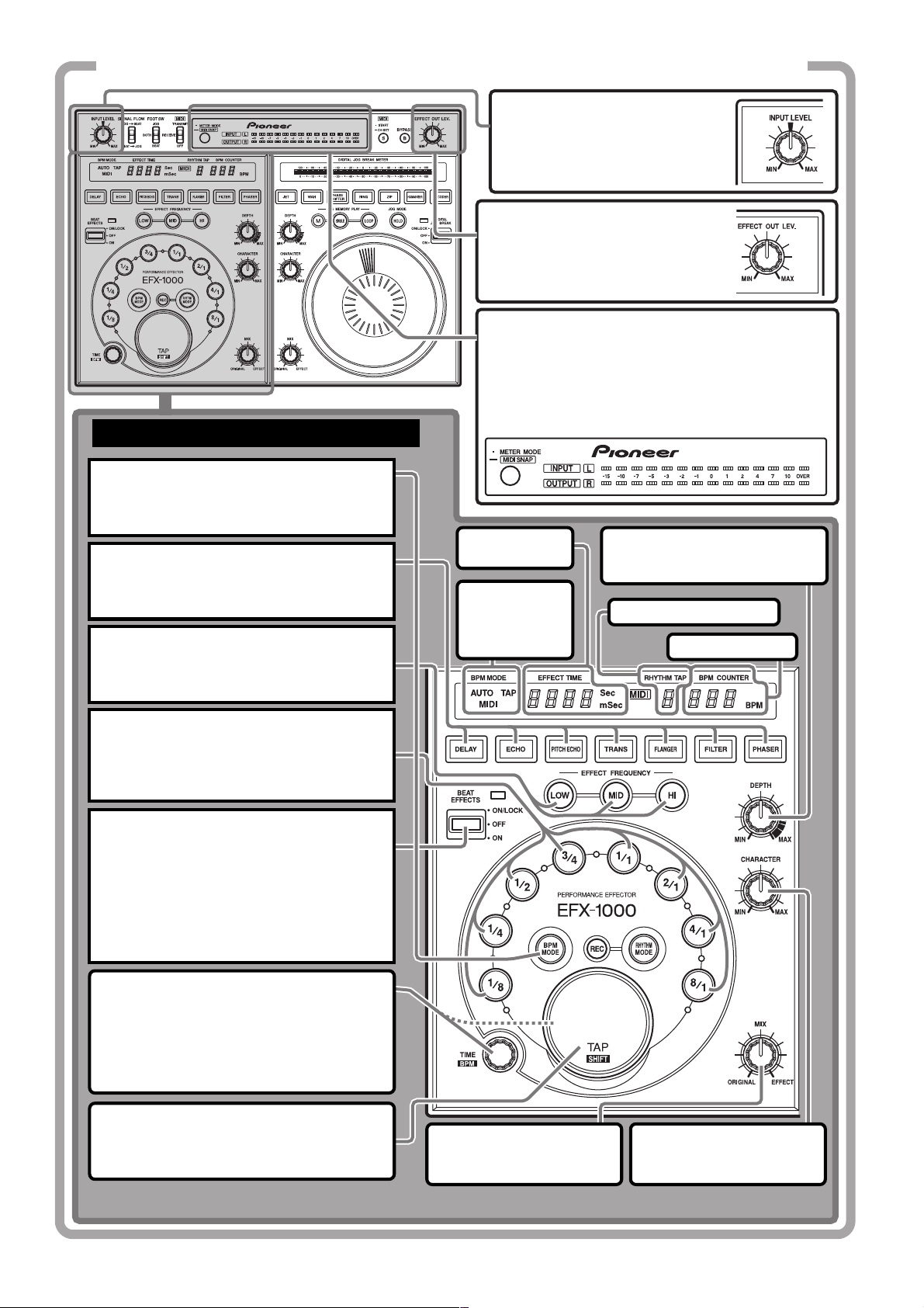
QUICK OPERATION GUIDE (1/3)
Adjusting the input level
Input signals to the input
connectors, and adjust the
INPUT LEVEL dial.
Adjusting effect output level
Rotate the EFFECT OUT LEV. dial to
adjust the effect output level.
Changing the level meter display mode
Each time the METER MODE button is pressed, the
level meter display alternates as follows:
÷ INPUT, OUTPUT light: Input and output monaural
display.
÷ INPUT, L, R light: Input stereo display.
USING BEAT EFFECTS [BPM MODE]
1. Select the BPM measurement mode.
Press the BPM MODE button so that the
button lights together with the desired mode
indicator (AUTO/MIDI/TAP).
2. Select effect type.
Press the DELAY, ECHO, PITCH ECHO,
TRANS, FLANGER, FILTER or PHASER button
and the pressed button starts to flash.
3. Select the sound range for the effect.
Press the button of the frequency (LOW, MID,
HI) you wish to affect by the beat effect and
the corresponding indicator lights.
OUTPUT, L, R
÷
EFFECT TIME
display
BPM
measurement
mode
indicators
light: Output stereo display.
DEPTH dial
Sets the parameter 1 of each
effect.
RHYTHM TAP display
BPM COUNTER
4. Select the beat with which the effect is
to be synchronized.
Press a beat select button (1/8, 1/4, 1/2, 3/4,
1/1, 2/1, 4/1 or 8/1) to light the desired button.
5. Apply an effect.
Press the lever towards you (ON position) to
start operation; release it and it returns to
the center position (OFF position). In the
center position (OFF position), the original
sound is not affected. Press the lever away
from you to lock it in position so that the
beat effect is applied also when the lever is
released.
TIME/BPM dial
Set the desired effect time as in step 4.
Turn the TIME/BPM dial while holding down
the TAP/SHIFT button to make the desired
BPM setting. When also the BPM MODE
button is held down, BPM can be set in 0.1
increments.
TAP/SHIFT button
BPM can be manually adjusted by adjusting
the beat (quarter notes) and hitting this key
two times or more.
MIX dial
Adjusts the balance between
the original sound and effects.
CHARACTER dial
Sets the parameter 2 of each
effect.
6
<DRB1368>
Page 7
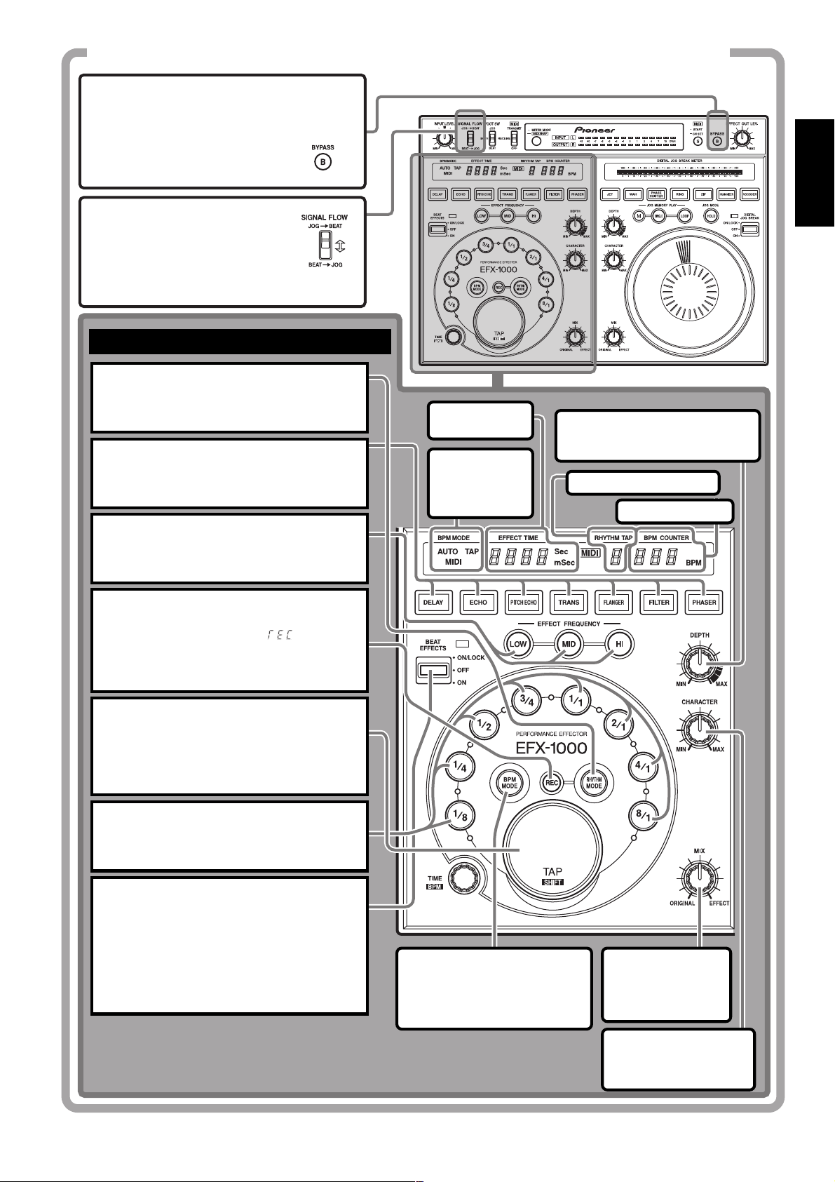
QUICK OPERATION GUIDE (2/3)
BYPASS button
When the button is pressed (button
indicator flashes), the signal entering
the input connectors is output
directly (without modification) to the
output connectors.
SIGNAL FLOW switch
Selects the order in which signals
are passed through the electronic
sections (from beat effect to digital
jog break, or vice versa).
USING BEAT EFFECTS [RHYTHM MODE]
1. Select the rhythm input mode.
Press the RHYTHM MODE button so that the
button indicator lights.
2. Select effect type.
Press the DELAY, ECHO, PITCH ECHO, TRANS,
FLANGER, FILTER or PHASER button and the
pressed button starts to flash.
3. Select the sound range for the effect.
Press the button of the frequency (LOW, MID,
HI) you wish to affect by the rhythm effect and
the corresponding indicator lights.
EFFECT
TIME display
BPM
measurement
mode
indicators
DEPTH dial
Sets the parameter 1 of each
effect.
RHYTHM TAP display
BPM COUNTER
English
4. Set to REC mode.
¶ When the REC button is pressed, the
BPM display indicates “
¶ If no rhythm has been input, the unit
will automatically enter the REC mode
in step 1.
”.
5. Input the rhythm.
Tap your finger on the TAP button to input the
desired rhythm. As you input the rhythm, the
rhythm will be calculated and displayed on the
RHYTHM TAP display (up to 8 taps with tap
interval of 2 seconds or less).
6. Select the overall rhythm time.
The pressed beat select button will light, and
the overall rhythm time will be set at the
multiple corresponding to the pressed button.
7. Apply an effect.
Press the lever towards you (ON position) to
start operation; release it and it returns to the
center position (OFF position). In the center
position (OFF position), the original sound is
not affected. Press the lever away from you to
lock it in position so that the rhythm effect is
applied also when the lever is released.
BPM MODE button
When the BPM MODE button is
pressed while in the rhythm
mode, the mode changes to
the beat effect BPM mode.
MIX dial
Adjusts the balance
between the original
sound and effects.
CHARACTER dial
Sets the parameter 2 of
each effect.
<DRB1368>
7
Page 8
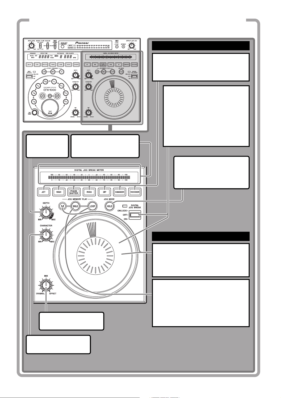
QUICK OPERATION GUIDE (3/3)
USING THE DIGITAL JOG BREAK
1. Select the desired effect.
Press the desired effect button, JET, WAH,
PHASE SHIFTER, RING, ZIP, HUMANIZER or
VOCODER to flash the corresponding button.
2. Apply the desired effect.
Turn the Jog dial either while pressing the
lever towards you or pressing it away
from you (ON position). As the Jog dial is
turned, parameters change gradually and
the selected effect is applied. When the
dial rotation is stopped, the parameter
returns to normal.
When the lever is pressed towards you,
releasing it causes it to automatically
DEPTH dial
Sets the parameter
1 of each effect.
DIGITAL JOG BREAK METER
Indicates the amount of control
exercised by the Jog dial.
return to the center (OFF position).
MIX dial
Adjusts the balance between
the original sound and effects.
HOLD button
When this button is pressed so that
the button indicator lights, effects
produced with the Jog dial will
continue even when your hand is
removed from the dial.
USING JOG MEMORY PLAY
1. Hold the Jog memory button (M)
depressed while rotating the Jog dial.
Effect changes produced with the Jog dial will be
stored in memory (maximum 8 seconds). When
storage is completed, the SINGLE and LOOP
buttons light.
2. Press the SINGLE button or LOOP
button
÷ When the SINGLE button is pressed, the
stored Jog-dial effect change will be replayed
one time only.
÷ When the LOOP button is pressed, the stored
Jog-dial effect change will be replayed
repeatedly. Press the button once more to stop
the effect.
CHARACTER dial
Sets the parameter 2 of each
effect.
8
<DRB1368>
Page 9
CONNECTIONS
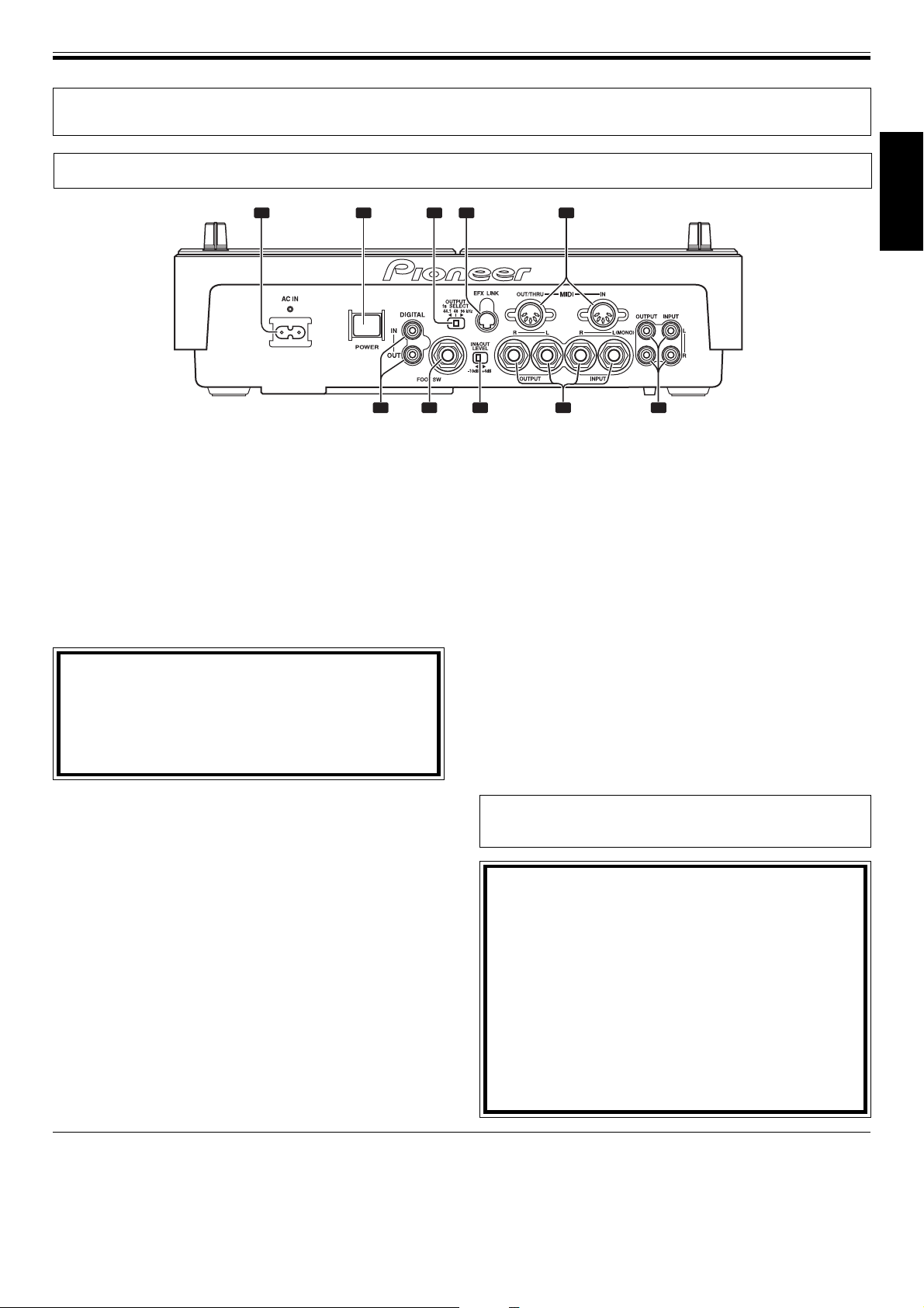
Connection Panel
BEFORE USE (CONNECTIONS)
2 3 4 51
6 7 8 9 10
1 Power input socket (AC IN)
Use the provided power cord to connect this socket to an
AC outlet.
2 POWER switch
3 Digital OUTPUT fs SELSECT switch
Use to change the digital output frequency sampling rate
(fs) (44.1kHz/48kHz/96kHz).
4 Link input/output connector (EFX LINK)
When the accessory digital link cable is used to connect
this connector to the DJ-mixer DJM-1000 (with digital link
support), digital link functions can be used, permitting a
variety of new functions.
CAUTION:
The EFX LINK connector is designed to be connected
via the provided digital link cable ONLY to a component
equipped with the designated digital link function.
The unit may be damaged if this connector is
mistakenly connected to any other component.
5. MIDI input/output connectors (MIDI OUT/THRU,
MIDI IN)
Use to connect the effector to a MIDI component (see page 23).
6 Digital input/output connectors (DIGITAL IN,
DIGITAL OUT)
Use to connect the effector to a component provided with
coaxial digital input/output connectors.
7 Foot switch jack (FOOT SW)
Can be connected to a ON/OFF type foot switch with 6.3mm
phone plug to allow ON/OFF control of effects.
Foot switches are available in several types, including
press-ON, press-OFF, and latching-type ON/OFF.
8 Input/output gain select switch (IN&OUT LEVEL)
Use to select the input/output gain (–10dB / +4dB).
9 Audio INPUT/OUTPUT jacks
Uses 6.3mm phones plug. For monaural inputs, connect L
input channel only for output on both L and R channels.
Audio inputs are throughput (output) even when the unit’s
power is turned OFF.
10 Audio INPUT/OUTPUT jacks
INPUT/OUTPUT connectors using RCA pin jacks.
Audio inputs are throughput (output) even when the unit’s
power is turned OFF.
7
Before making or changing the connections,
switch off the power switch and disconnect the
power cord from the AC outlet. This precaution
should also be taken when changing the IN & OUT
LEVEL switch and DIGITAL fs SELECT switch.
÷ When connections are made to the phone jack inputs
and a monaural signal cable is connected to the L
(MONO) terminal, inputs can be made to both the L and
R channels.
÷ After all other connections are made, connect the power
cord to a household wall outlet or to the auxiliary AC
power takeoff on your amplifier.
See page 23 for instructions on how to
use the MIDI terminals.
CAUTION:
Do not make any connections that may create signal
loops as this will cause circuit oscillations which
could damage the speakers.
[Example of connections that must not be
performed]
¶ Do not connect the output of the DJ Mixer to the
input terminal of the Effector and the output of the
Effector to the input terminal of the same mixer.
¶ Do not connect the SEND output of the DJ Mixer to
the input terminal of the Effector and the output of
the Effector to the input terminal of the DJ Mixer
(except for the RETURN terminal).
English
Installation Location
÷ Avoid mounting on top of amplifiers, near spotlights, or
other heat-emitting components and appliances;
extended exposure to heat can cause damage to the
effector itself.
÷ Install this unit as far as possible away from tuners and TV
sets. A unit installed in close proximity to such equipment
may cause noise or degradation of the picture.
Cleaning the unit
To clean the unit wipe with a polishing or a soft, dry cloth.
For stubborn dirt, moisten a soft cloth with a weak solution
of neutral detergent (diluted in five to six parts water),
wring the cloth well, and wipe away the dirt. Use a dry cloth
to wipe the surface dry. Do not use volatile liquids such as
benzene or thinner which will damage to the unit.
<DRB1368>
9
Page 10
BEFORE USE (CONNECTIONS)
Basic Connections
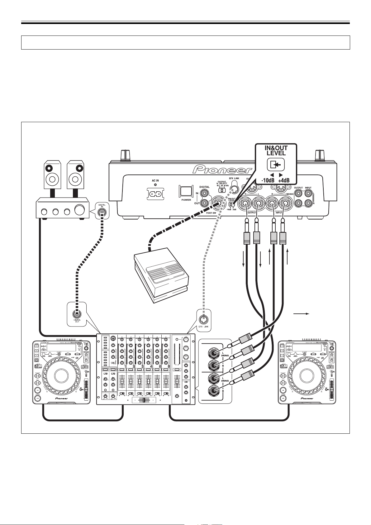
Before making or changing the connections, switch off the power switch and disconnect the power cord from the AC outlet.
1. Connecting the SEND/RETURN Terminals on the
DJ Mixer (on DJ mixer provided with SEND and
RETURN terminals)
÷ Make connections using cables with 1/4-inch/6.3 mm in
diameter phone plugs.
÷ Set the DJ mixer so that the SEND and RETURN
terminals can be used.
Effector EFX-1000
Stereo Amplifier
÷ If the DJ mixer supports digital link, it can be connected
to the EFX LINK connector using the provided digital link
cable to eliminate the need for connection by an analog
6.3mm phone plug cable (audio signals transmitted over
the digital link cable are in digital format).
÷ Set the IN & OUT LEVEL switch on the Effector
to the [–10 dB] position.
FOOT SW
OUTPUT
INPUT
EFX LINK
Accessory
digital
Foot switch
link cable
(pedal switch)
: Signal flow
MASTER OUT
DJ CD Player DJ CD Player
CH-1
DJ Mixer
SEND
SEND 1
–26 +6
RETURN
RETURN 1
CH-2
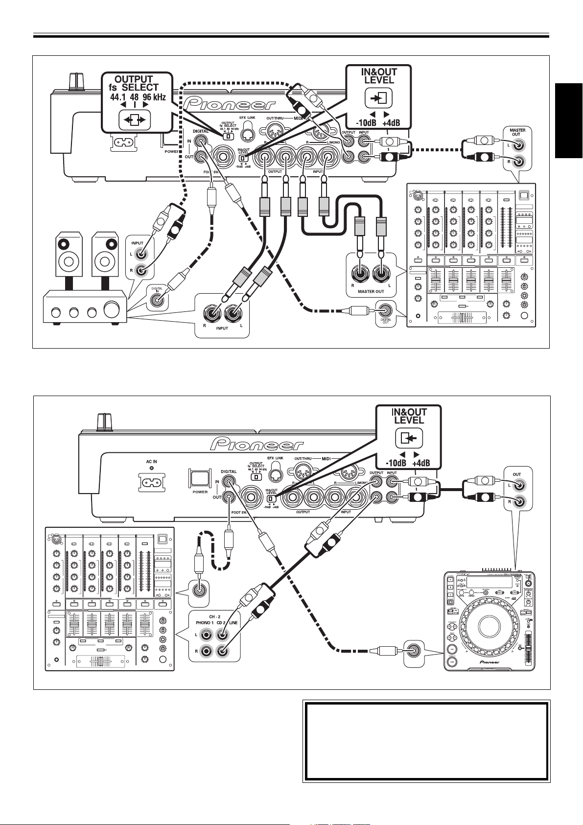
2. Connecting a DJ Mixer and an Audio Amplifier
(on DJ mixer not provided with SEND and
RETURN terminals)
÷ Connect using cables with phone plugs (1/4-inch/6.3 mm
in diameter) or RCA pin plugs.
10
<DRB1368>
÷ When making connections, do not connect both RCA pin
plug cables and phones plug cables for the same
connection function (use either one or the other, not
both). Also, if you wish to use analog connections, do
not also make connections to the digital connectors
(digital signals are given priority when connected).
¶ For digital connections, use RCA pin-plug coaxial cables.
Set the OUTPUT fs SELECT switch in accordance with
the connected component.
Page 11
BEFORE USE (CONNECTIONS)
Effector EFX-1000
Stereo Amplifier
OUTPUT
L
R
÷ Set the IN & OUT LEVEL switch
on the Effector to the [+4 dB]
position.
MASTER OUT
L
R
L
R
English
INPUT
INPUT
L
R
MASTER OUT
DIGITAL OUT
DJ Mixer
3. Connecting a DJ CD Player and a DJ Mixer (this
connection applies effects only to the sound of
the DJ CD player on channel 2)
Effector EFX-1000
DIGITAL OUT
DIGITAL
DIGITAL
IN
IN
L
R
DIGITAL
IN
¶ Connect the units using a cable with RCA pin plugs.
¶ For digital connections, use RCA pin-plug coaxial cables.
÷ Set the IN & OUT
LEVEL switch on the
Effector to the [–10 dB]
position.
AUDIO OUT
L
R
INPUT
L
OUTPUT
R
DIGITAL OUT
L
R
DJ Mixer
4. Connecting the power cord
÷ After all other connections are completed, insert the
power cord’s plug into a wall power outlet or the
auxiliary power outlet of an amplifier.
DIGITAL
OUT
DJ CD Player
CAUTION:
Signal inputs are handled in a specific order of
priority:
EFX LINK > digital inputs > analog inputs
When EFX LINK signals are input, digital signals are
not output.
<DRB1368>
11
Page 12
EFFECTS (Beat Effects)
EFFECTS
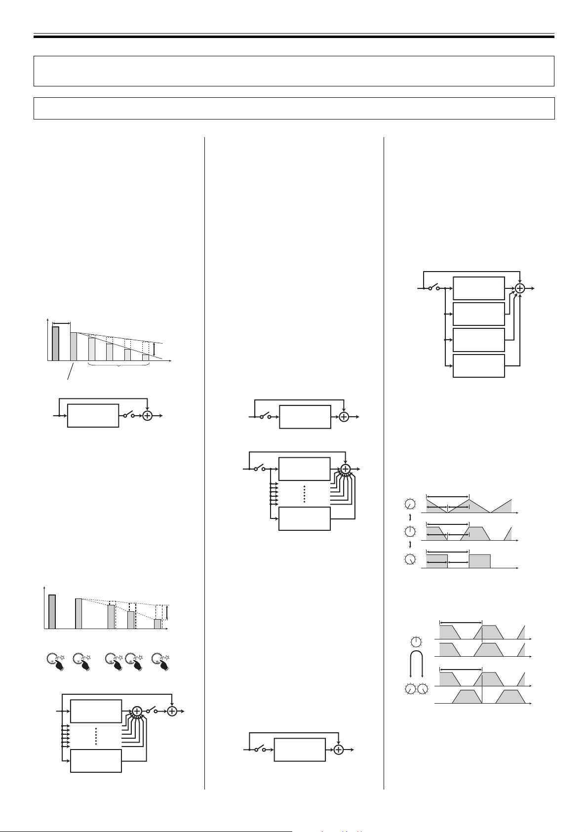
Beat Effects
1. DELAY effect
Adds delay sound to the original sound.
[BPM mode]
A delay sound is added to the original
sound at the value set with the TIME dial.
÷ The DEPTH dial can be used to adjust
the feedback level. Feedback means to
input the delay sound back into the
delay input. This control allows the
amount of the feedback to be adjusted
(near the [MAX] setting, the sound level
rises).
÷ The CHARACTER dial can be used to
adjust the amount of filter applied to the
feedback sound.
÷ The MIX dial can be used to adjust the
levels of the original and delay sounds.
TIME
Sound level
Original
sound
Delay sound
Delay block
Feedback
[RHYTHM mode]
A delay sound set with the TAP button
(TAP delay sound) is added to the original
sound (Max 8-TAP).
÷ The DEPTH dial can be used to adjust
the TAP delay level (near the [MAX]
setting the sound volume will rise).
÷ The CHARACTER dial can be used to
adjust the amount of filter applied to the
TAP delay sound.
÷ The MIX dial can be used to adjust the
levels of the original and TAP delay
sounds.
Sound level
Original
Delay
sound
sound
TAP 0 TAP 1 TAP 2 TAP 3 TAP 4
TAP 1 delay
block
TAP 8 delay
block
Delay
sound
Delay
sound
DEPTH
Delay
sound
Time
DEPTH
Time
2. ECHO effect
Adds delay sound to the original sound.
[BPM mode]
A delay sound is added to the original
sound at the value set with the TIME dial.
[RHYTHM mode]
Adds TAP delay sound to the original
sound (Max 8-TAP).
Difference from the DELAY effect:
÷ Even if the BEAT EFFECTS lever switch
is moved from [ON] to [OFF], the
feedback sound or TAP delay sound will
continue.
÷ In the BPM mode, if the DEPTH dial is
set to [MAX] and the BEAT EFFECTS
lever switch is moved from [ON] to
[OFF], a hold-delay effect will be
produced without attenuating the
feedback sound (near the [MAX] setting,
the sound level rises).
In the RHYTHM mode, when the switch
is turned [OFF] the effect will end with
the final TAP delay sound for the
original sound.
BPM mode
Echo block
RHYTHM mode
TAP 1 echo
block
TAP 8 echo
block
3. PITCH ECHO effect
Changes the pitch of the delay sound, and
applies the effect to the original sound.
In the same way as for the ECHO effect, the
effect sound is maintained even if the BEAT
EFFECTS lever switch is set from [ON] to
[OFF].
[BPM mode]
Changes the pitch of the delay sound set
with the TIME dial, and applies the effect to
the original sound.
÷ The DEPTH dial can be used to adjust
the feedback level.
÷ The CHARACTER dial can be used to
adjust the pitch of the delay sound.
÷ The MIX dial can be used to adjust the
levels of the original and pitch echo
sounds.
Pitch echo
block
[RHYTHM mode]
Changes the pitch of the TAP delay sound,
and applies the effect to the original sound
(Max 4-TAP).
÷ The DEPTH dial can be used to adjust
the TAP delay level (near the [MAX]
setting the sound volume will rise
somewhat).
÷ The CHARACTER dial can be used to
adjust the pitch of the TAP delay sound.
÷ The MIX dial can be used to adjust the
levels of the original and pitch echo
sounds.
TAP 1 pitch
echo block.
TAP 2 pitch
echo block.
TAP 3 pitch
echo block.
TAP 4 pitch
echo block.
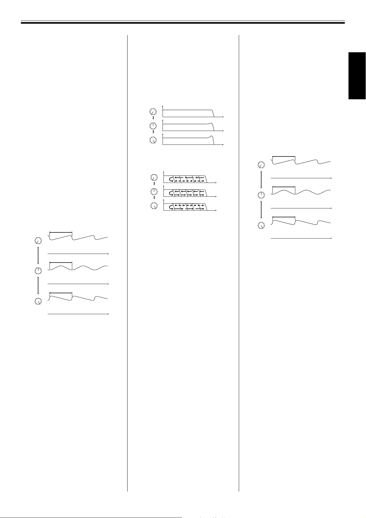
4. TRANS effect
Cuts the original sound intermittently.
[BPM mode]
Cuts the sound at the interval set by the
TIME dial (cuts latter half of the interval).
÷ The DEPTH dial can be used to adjust
the amount of shift when the sound is
cut.
DEPTH
MIN
DEPTH
DEPTH
÷ The CHARACTER dial can be used to
adjust the phase difference between L
and R channels.
CHARACTER
CHARACTER
÷ The MIX dial can be used to adjust the
levels of the original and trans sounds.
TIME
TIME
TIME
MAX
TIME
L-ch
R-ch
TIME
L-ch
MAXMIN
R-ch
Time
Time
Time
Time
Time
Time
Time
12
<DRB1368>
Page 13
EFFECTS (Beat Effects)
[RHYTHM mode]
Cuts the original sound in synch with the
TAP rhythm (Max 8-TAP).
÷ The DEPTH dial can be used to adjust the
amount of shift when the sound is cut.
÷ The CHARACTER dial can be used to
adjust of phase difference between L
and R channels.
÷ The MIX dial can be used to adjust the
levels of the original and trans sounds.
5. FLANGER effect
By applying a time-shifted sound to the
original, the effect of an ascending or
descending jet plane (flange effect) is
produced.
[BPM mode]
Changes the frequency range to which the
flange effect is applied at the interval set by
the TIME dial.
÷ The DEPTH dial can be used to adjust
the strength of the flange effect by
changing the amount of resonance.
(When approaching the [MAX] setting,
the level of the sound increases.)
÷ The CHARACTER dial can be used to
adjust the cyclic changes in the flange
effect.
÷ The MIX dial can be used to adjust the
levels of the original and flanger sounds.
CHARACTER
MIN
CHARACTER
CHARACTER
[RHYTHM mode]
Changes the frequency subjected to flange
effect, in synch with the TAP rhythm.
÷ The DEPTH dial can be used to adjust
the strength of the flange effect by
changing the amount of resonance.
(When approaching the [MAX] setting,
the level of the sound increases.)
÷ The CHARACTER dial can be used to
adjust the cyclic changes in the flange
effect.
÷ The MIX dial can be used to adjust the
levels of the original and flanger sounds.
TIME
Flange effect change
TIME
Flange effect change
TIME
MAX
Flange effect change
Time
Time
Time
6. FILTER effect
A low-pass filter is applied to the original
sound to produce more muted sound.
[BPM mode]
The cutoff frequency of the low-pass filter
changes with the cycle set by the TIME dial.
÷ The DEPTH dial is used to change the
unique coloring of the sound by
adjusting the amount of resonance.
(When approaching the [MAX] setting,
the level of the sound increases.)
DEPTH
MIN
DEPTH
DEPTH
MAX
÷ The CHARACTER dial can be used to
vary the cutoff frequency of the cyclic
low-pass filter.
CHARACTER
MIN
CHARACTER
CHARACTER
MAX
÷ The MIX dial can be used to adjust the
levels of the original and filter sounds.
[RHYTHM mode]
Changes cutoff frequency of the low-pass
filter, in synch with the TAP rhythm (Max 8TAP).
÷ The DEPTH dial is used to change the
unique coloring of the sound by
adjusting the amount of resonance.
(When approaching the [MAX] setting,
the level of the sound increases.)
÷ The CHARACTER dial can be used to
vary the cutoff frequency of the cyclic
low-pass filter.
÷ The MIX dial can be used to adjust the
levels of the original and filter sounds.
7. PHASER effect
Causes a phase effect by applying a phaseshifted sound to the original sound.
[BPM mode]
Changes the frequency range to which the
phase effect is applied at the interval set by
the TIME dial.
÷ The DEPTH dial can be used to adjust
the strength of the phase effect by
changing the amount of resonance.
(When approaching the [MAX] setting,
the level of the sound increases.)
÷ The CHARACTER dial can be used to
adjust the cyclic changes in the phase
effect.
÷ The MIX dial can be used to adjust the
levels of the original and phaser
sounds.
CHARACTER
MIN
CHARACTER
CHARACTER
[RHYTHM mode]
Changes the frequency subjected to phase
effect, in sync with the TAP rhythm.
÷ The DEPTH dial can be used to adjust
the strength of the phase effect by
changing the amount of resonance.
(When approaching the [MAX] setting,
the level of the sound increases.)
÷ The CHARACTER dial can be used to
adjust the cyclic changes in the phase
effect.
÷ The MIX dial can be used to adjust the
levels of the original and phaser
sounds.
TIME
Phase effect change
TIME
Phase effect change
TIME
MAX
Phase effect change
Time
Time
Time
English
13
<DRB1368>
Page 14
EFFECTS (Digital Jog Break)
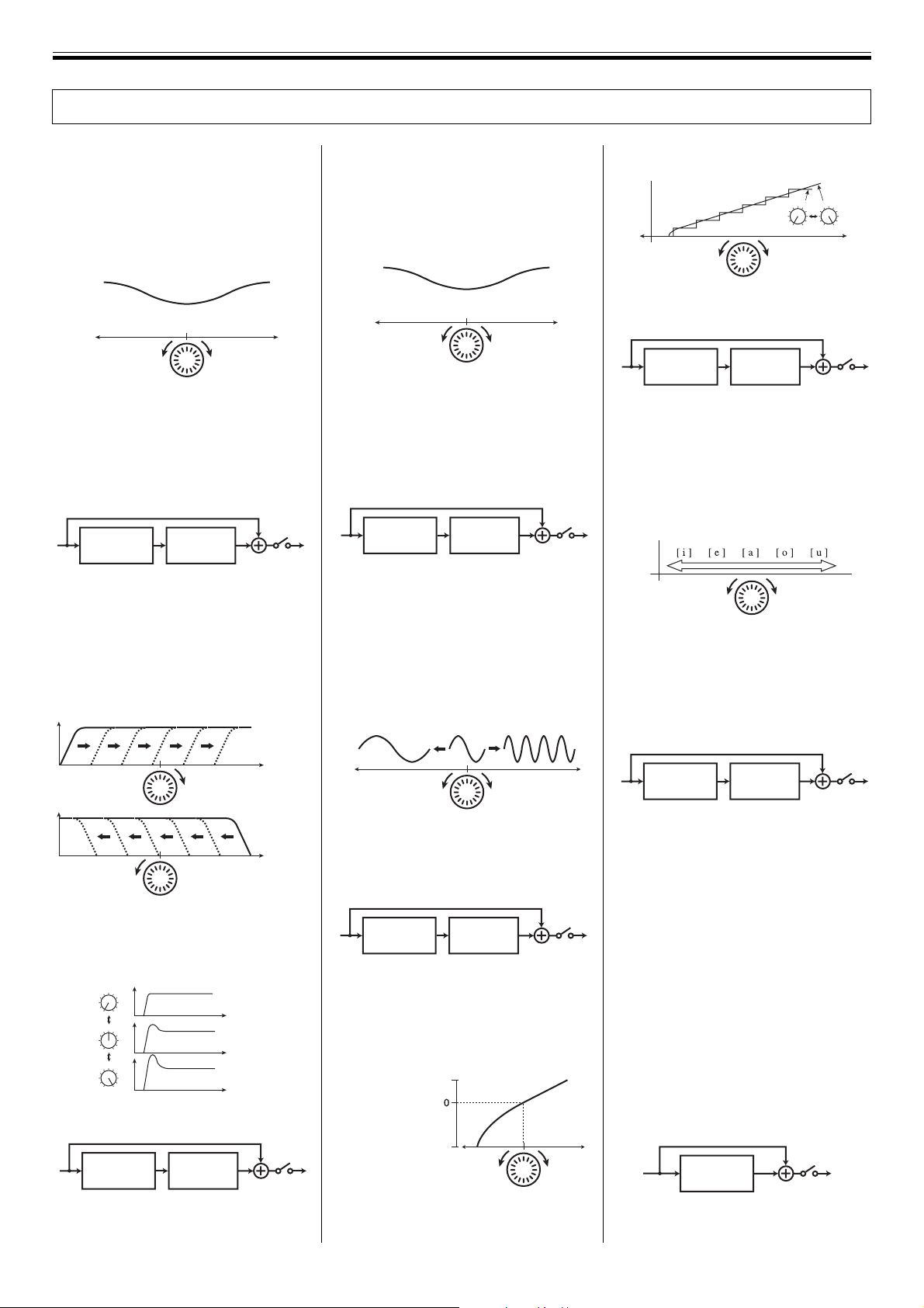
Digital Jog Break
1. JET effect
A time-shifted sound is applied to the
original, thus producing the effect of a jet
airplane ascending or descending (flange
effect).
÷ The Jog dial is used to change the
frequency range that is affected by the
flange effect.
Flange effect change
REV
Jog dial
FWD
÷ The amount of resonance is changed
using the DEPTH dial to emphasize the
flange effect. (When approaching the
[MAX] setting, the level of the sound
increases.)
÷ The CHARACTER dial can be used to
adjust the reverb effect.
Jet block
Reverb
block
÷ The MIX dial can be used to adjust the
levels of the jet + reverb sound and
original sound.
2. WAH effect
The filter’s cutoff frequency is shifted,
causing great change in the sound tone.
÷ The Jog dial is used to vary the filter’s
cutoff frequency.
3. PHASE SHIFTER effect
A phase-shifted sound is added to the
original, thus producing a phase shifter
effect.
÷ The Jog dial is used to change the
frequency range that is affected by the
phase effect.
Phase effect change
REV
Jog dial
FWD
÷ The amount of resonance is changed
using the DEPTH dial to emphasize the
phase effect. (When approaching the
[MAX] setting, the level of the sound
increases.)
÷ The CHARACTER dial can be used to
adjust the reverb effect.
Phase shifter
block
Reverb
block
÷ The MIX dial can be used to adjust the
levels of the phase shifter + reverb
sound and the original sound.
4. RING modulator effect
By modulating the original sound in the
shape of a sine wave, the resulting sound
coloration resembles a ringing bell.
÷ The Jog dial is used to vary the sine
wave frequency.
÷ The DEPTH dial can be used to adjust
the Jog dial’s variable range (step).
DEPTH
DEPTH
MIN
MAX
REV FWD
Jog dial
÷ The CHARACTER dial can be used to
adjust the reverb effect
Zip block
Reverb
block
÷ The MIX dial can be used to adjust the
levels of the zip+reverb and original
sounds.
6. HUMANIZER effect
The original sound is modified to resemble
the vowel sounds of the human voice.
÷ The Jog dial is used to vary the vowel
sound coloration.
REV FWD
Jog dial
÷ The DEPTH dial is used to change the
unique coloring of vowel sounds by
adjusting the amount of resonance.
(When approaching the [MAX] setting,
the level of the sound increases.)
÷ The CHARACTER dial can be used to
adjust the reverb effect.
Frequency
Jog dial
Frequency
Jog dial
÷ The DEPTH dial is used to change the
unique coloring of the sound by
adjusting the amount of resonance.
(When approaching the [MAX] setting,
the level of the sound increases.)
DEPTH
MIN
DEPTH
DEPTH
MAX
Frequency
Frequency
Frequency
÷ The CHARACTER dial can be used to
adjust the reverb effect.
Wah block
Reverb
block
÷ The MIX dial can be used to adjust the
levels of the wah + reverb sound and the
original sound.
REV
Jog dial
FWD
÷ The DEPTH dial can be used to adjust
the amplitude of the sine wave.
÷ The CHARACTER dial can be used to
adjust the reverb effect.
Ring block
Reverb
block
÷ The MIX dial can be used to adjust the
levels of the ring + reverb and original
sounds.
5. ZIP effect
The Jog dial is used to change the pitch.
Up (about 1 octave)
’
Pitch
Down
(about 15 octaves)
Original
‘
sound
REV
FWD
Jog dial
Humanizer
block
Reverb
block
÷ The MIX dial can be used to adjust the
levels of the humanizer + reverb and the
original sounds.
7. VOCODER effect
The input sound is replaced by an internally generated signal sound, producing a
mechanical sound effect.
÷ The Jog dial is used to change the
frequency of the internally generated
signal sound.
÷
The DEPTH dial can be used to vary the
internally generated sound from the basic
sound to a chord. (The sound more nearly
approximates the chord as the adjustment
approaches the [MAX] setting.)
÷ The CHARACTER dial can be used to
change chords codes. Selectable codes
include Minor (MIN), Minor7, 7, Major
(center position), Major7, Sus4, and Add9
(MAX).
Vocoder
block
÷ The MIX dial can be used to adjust the
levels of the vocoder and original sounds.
14
<DRB1368>
Page 15

Effect Parameters
Beat effect
EFFECTS (Effect Parameters)
DELAY
ECHO
PITCH
ECHO
TRANS
FLANGER
FILTER
PHASER
Parameter 0
(TIME)
BPM MODE
○○○○○○○○○○○○○○○○○○○○○○○○○○○○○○○○○○○○○○○○○○○○○○○○○○○○○○○○○○○
RHYTHM MODE
BPM MODE
○○○○○○○○○○○○○○○○○○○○○○○○○○○○○○○○○○○○○○○○○○○○○○○○○○○○○○○○○○○
RHYTHM MODE
BPM MODE
○○○○○○○○○○○○○○○○○○○○○○○○○○○○○○○○○○○○○○○○○○○○○○○○○○○○○○○○○○○
RHYTHM MODE
BPM MODE
○○○○○○○○○○○○○○○○○○○○○○○○○○○○○○○○○○○○○○○○○○○○○○○○○○○○○○○○○○○
RHYTHM MODE
BPM MODE
○○○○○○○○○○○○○○○○○○○○○○○○○○○○○○○○○○○○○○○○○○○○○○○○○○○○○○○○○○○
RHYTHM MODE
BPM MODE
○○○○○○○○○○○○○○○○○○○○○○○○○○○○○○○○○○○○○○○○○○○○○○○○○○○○○○○○○○○
RHYTHM MODE
BPM MODE
○○○○○○○○○○○○○○○○○○○○○○○○○○○○○○○○○○○○○○○○○○○○○○○○○○○○○○○○○○○
RHYTHM MODE
1~16000 [ms]
1~16000 [ms]*
1~16000 [ms]
1~16000 [ms]*
1~16000 [ms]
1~16000 [ms]*
10~16000 [ms]
10~16000 [ms]*
10~32000 [ms]
10~32000 [ms]*
10~32000 [ms]
10~32000 [ms]*
10~32000 [ms]
10~32000 [ms]*
Parameter 1
(DEPTH)
Feedback
(feedback level)
TAP gain
(TAP delay level)
Feedback
(feedback level)
TAP gain
(TAP delay level)
Feedback
(feedback level)
TAP gain
(TAP delay level)
Shape
(cut shift)
Shape
(cut shift)
Resonance
Resonance
Resonance
Resonance
Resonance
Resonance
Parameter 2
(CHARACTER)
Feedback filter
(Amount of
feedback filter)
TAP filter
(Amount of TAP
delay filter)
Feedback filter
(Amount of
feedback filter)
TAP filter
(Amount of TAP
delay filter)
Pitch
(delay sound pitch)
TAP Pitch
(TAP delay sound pitch)
Phase
(L/R-ch phase
difference)
Phase
(L/R-ch phase
difference)
LFO pattern
(change cyclic effect)
LFO pattern
(change cyclic effect)
LFO pattern
(change cyclic effect)
LFO pattern
(change cyclic effect)
LFO pattern
(change cyclic effect)
LFO pattern
(change cyclic effect)
Parameter 3
(MIX)
MIX
MIX
MIX
MIX
MIX
MIX
MIX
MIX
MIX
MIX
MIX
MIX
MIX
MIX
Comments
—
Max 8-TAP
—
Max 8-TAP
—
Max 4-TAP
—
Max 8-TAP
—
Max 8-TAP
—
Max 8-TAP
—
Max 8-TAP
* The effect time display in the rhythm mode shows the total time from the beginning to end of TAP
input. For this reason, the noted MIN time may be somewhat different from the effect time display.
English
Digital Jog Break
JET
WAH
PHASE SHIFTER
RING
ZIP
HUMANIZER
VOCODER
Parameter 0
(JOG)
Delay time
(amount of delay)
Frequency
(filter frequency)
Frequency
(filter coefficient)
Frequency
(sine wave frequency)
Pitch
(Scale)
Vowel
(vowel sound)
Oscillator frequency
(internally generated
sound frequency)
Parameter 1
(DEPTH)
Resonance
Resonance
Resonance
Amplitude
(sine-wave amplitude
Step
(ScaleÔLinear)
Resonance
Chord MIX
(chord MIX ratio)
Parameter 2
(CHARACTER)
Reverb
(reverberation effect)
Reverb
(reverberation effect)
Reverb
(reverberation effect)
Reverb
)
(reverberation effect)
Reverb
(reverberation effect)
Reverb
(reverberation effect)
Chord
Parameter 3
(MIX)
MIX
MIX
MIX
MIX
MIX
MIX
MIX
Comments
—
—
—
—
—
—
—
15
<DRB1368>
Page 16
BEFORE USE (CONTROLS AND FUNCTIONS)
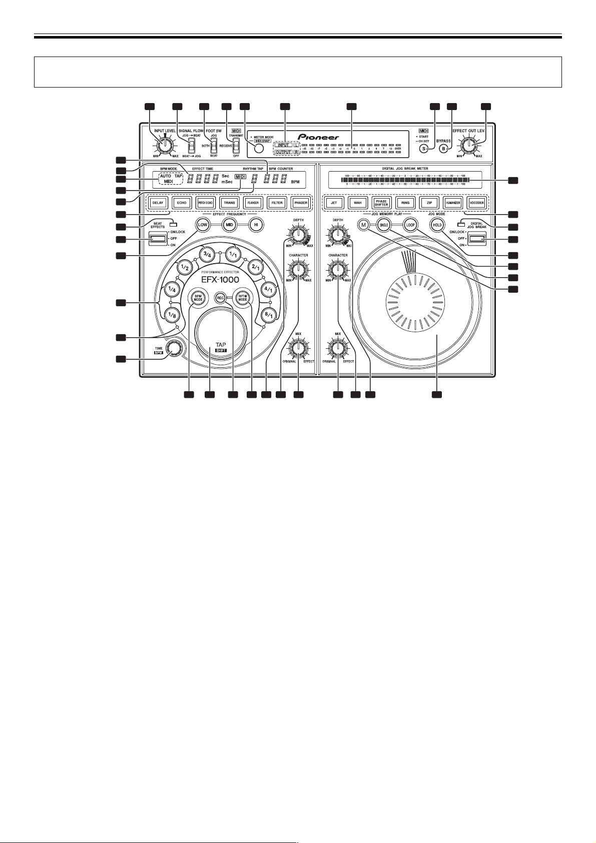
CONTROLS AND FUNCTIONS
1
Control Panel
11
12
13
14
15
16
17
18
19
20
2 3 4 6 7 8 9 10
5
41
40
39
38
37
36
35
34
21
22
23 24 25 26 27 28 29 30 31 32 33
1 INPUT LEVEL dial
Use to adjust the input level. Adjustment range is –∞ to
+9dB with analog inputs, and –∞ to 0dB with digital inputs.
2 SIGNAL FLOW switch
Use to select the order of signal flow between beat effect
and digital jog break sections.
JOG = BEAT:
Signals travel through the digital jog break section before
passing to the beat effect section.
BEAT = JOG:
Signals travel through the beat effect section before
passing to the digital jog break section.
3 Foot switch mode selector (FOOT SW)
Use to select which function is controlled (ON/OFF) by an
attached foot switch (pedal switch).
BEAT:
Attached foot switch controls beat effect function (ON/OFF).
JOG:
Attached foot switch controls digital jog break function
(ON/OFF).
BOTH:
Attached foot switch controls both beat effect function and
digital jog break function (ON/OFF).
4 MIDI mode select switch
Select MIDI communication between computer and other
instruments, etc.
TRANSMIT:
Acts as MIDI controller
RECEIVE:
Effector can be controlled by MIDI signals.
OFF:
Acts as effector (communication OFF)
5 METER MODE/MIDI SNAP button
[Use to switch the function of the level meter display.]
Each time the button is pressed, the level meter display
switches between input and output monaural display,
input stereo display, and output stereo display.
[MIDI Snapshot Mode]
When this button is held depressed with the MIDI mode set
to [TRANSMIT], a snapshot will be sent to the external MIDI
component.
6 Level meter mode display (INPUT, OUTPUT, L, R)
Input and output monaural display:
Both [INPUT] and [OUTPUT] indicators light.
Input stereo display:
[INPUT] and [L], [R] indicators light.
Output stereo display:
[OUTPUT] and [L], [R] indicators light.
7 Level meter display
8 MIDI START/CH SET button / indicator
[MIDI START]
If this button is pressed when MIDI mode is set to
[TRANSMIT], the MIDI start/stop signal is output.
Lights steadily with START, and goes out with STOP.
[MIDI channel setting (CH SET)]
If this button is held depressed when MIDI mode is set to
[TRANSMIT] or [RECEIVE], the MIDI indicator flashes and
the MIDI setting mode is enabled.
16
<DRB1368>
Page 17

BEFORE USE (CONTROLS AND FUNCTIONS)
9 BYPASS button / indicator
When this button is set to ON, the audio input connector
signals are fed directly to the output connectors, bypassing
the effector circuits.
When the audio input/output connectors are connected
directly in this way, the indicator flashes.
10 EFFECT OUT LEV. dial
When effects are set to ON, this dial can be used to control
the effect output level. Adjustment range is –∞ to +6dB.
Beat Effect section
11 BPM COUNTER display
Displays the beats-per-minute of the input source, or the
TAP input. The indicator flashes during automatic BPM
calculation. When power is first turned on, the counter will
flash [120 BPM].
12 EFFECT TIME display
Displays actual effect time.
When power is first turned on, defaults to [500 mSec].
13 BPM measurement mode display
(AUTO, MIDI, TAP).
Displays the BPM measurement mode.
20 Beat select buttons / indicators
(1/8, 1/4, 1/2, 3/4, 1/1, 2/1, 4/1, 8/1)
[During BPM mode]
When a BPM is measured automatically or input manually,
the beat select button [1/1] is selected by default. The effect
is synchronized automatically to the BPM, and the
corresponding effect time is displayed.
If a beat select button is then pressed, the effect is newly
synchronized to the corresponding multiple of the BPM (1/
8, 1/4, 1/2, 3/4, etc.), thus allowing one-touch change of the
BPM synchronization multiple. In turn, the selected beat
select button lights, thus showing to what multiple of the
actual BPM the effect is synchronized, as well as the
multiple of the time parameter.
[During RHYTHM mode]
When the rhythm input with the TAP button is established,
[1/1] is selected and a multiple of the rhythm can be
selected with the beat select buttons.
21 Beat effect beat-interval indicators
The indicators light to show the period of the effect time.
22 Beat effect TIME/BPM dial
When rotated the effect time selected with the beat select
buttons can be changed as desired.
If the dial is rotated while depressing the TAP button, the
BPM can be set as desired (BPM manual input).
English
14 MIDI display
Lights when handling MIDI data.
15 RHYTHM TAP display
Displays the tap count input in the rhythm mode.
16 Beat effect select button / indicator
(DELAY, ECHO, PITCH ECHO, TRANS, FLANGER,
FILTER, PHASER).
Use to select the beat effect. All buttons light, and selected
effect button flashes.
When power is turned ON, DELAY flashes.
17 BEAT EFFECTS indicator
Lights when beat effects are ON.
18 BEAT EFFECTS lever switch (OFF/ON/ON-LOCK)
Pull the lever toward you [ON] to output beat-effected
sounds.
In the middle position beat effects are [OFF]; push the lever
away from you to lock the lever in the [ON/LOCK] position
(effects are locked ON). When pulled to the [ON] position,
beat effects are output only while the lever is held; when
your finger is released, the lever returns to middle [OFF]
position.
23 BPM MODE button / indicator
Use to turn BPM mode ON, and to select tempo
measurement mode (AUTO/MIDI/TAP). During BPM mode,
the button lights.
If the TAP button is pressed (tapped) during BPM mode,
the mode switches to manual BPM measurement mode.
When power is first turned, the mode defaults to AUTO
measurement mode.
24 TAP/SHIFT button / indicator
[During BPM mode]
When this button is tapped, the BPM manual measurement
mode is selected, and the interval between two taps
(maximum interval 2 seconds) is measured; the
corresponding EFFECT TIME and BPM count is displayed,
and the beat select button [1/1] is selected.
If the TIME/BPM dial is rotated while pressing this button,
the BPM can be adjusted to an optional value (BPM manual
input).
[During RHYTHM mode]
When this button is tapped, the rhythm is input (maximum
tap interval 2 seconds, up to maximum rhythm count 8).
The beat select button [1/1] is selected.
[Tap indicator]
Lights during normal use; goes out only when TAP is
pressed.
19 EFFECT FREQUENCY select buttons (LOW/MID/HI)
Use to select the frequency band of the sounds to which
beat effects will be applied. The button of the selected band
will light.
When power is first turned ON, all three of the ranges LOW,
MID, and HI are selected. If all three range buttons are OFF,
no beat effects will be applied to sounds.
25 Rhythm REC button
Clears the currently input rhythm and allows input of a new
rhythm.
17
<DRB1368>
Page 18

BEFORE USE (CONTROLS AND FUNCTIONS)
26 RHYTHM MODE button / indicator
When this button is pressed, the RHYTHM mode is
selected, and the button lights.
27 Beat effect DEPTH dial
Allows adjustment of effect feedback and timing
parameters in accordance with the amount of rotation (see
page 15).
28 Beat effect CHARACTER dial
Allows adjustment of parameters other than those set with
the beat effect DEPTH dial (see page 15).
29 Beat effect MIX dial
Rotate to adjust the mixing balance of original and effect
sounds. When rotated fully to the [ORIGINAL] side, the
original (un-effected) sound will be output; as the dial is
rotated toward the [EFFECT] side, the effect sound is
amplified and the original sound decreases.
Digital Jog Break section
30 Digital jog break effect MIX dial
Rotate to adjust the mixing balance of original and effect
sounds. When rotated fully to the [ORIGINAL] side, the
original (un-effected) sound will be output; as the dial is
rotated toward the [EFFECT] side, the effect sound is
amplified and the original sound decreases.
31 Digital jog break effect CHARACTER dial
Allows adjustment of parameters other than those set with
the digital jog break DEPTH dial (see page 15).
32 Digital jog break DEPTH dial
Allows adjustment of effect feedback and timing
parameters in accordance with the amount of rotation (see
page 15).
33 Jog dial
Effect parameters change in response to the rotation of the
dial.
36 Jog memory LOOP play button / indicator
If the button is pressed while the button indicator is lighted,
the parameter change previously recorded in memory in
response to the Jog dial movement is reproduced (played
back repeatedly).
Press again to end Jog memory loop play.
Indicator lights when the jog operation is stored in
memory. Indicator flashes during jog memory loop play
(playback).
37 Jog HOLD button / indicator
When this button is pressed so that its indicator lights, the
effect produced when rotating the Jog dial is maintained
even if you remove your hand from the dial (when the hold
function is OFF, the effect returns to normal if your hand is
removed from the dial). When power is first turned on, the
button defaults to jog hold OFF (indicator is off).
38 DIGITAL JOG BREAK effect lever switch
(OFF/ON/ON-LOCK)
Pull the lever toward you [ON] to output effected sounds.
In the middle position effects are [OFF]; push the lever
away from you to lock the lever in the [ON/LOCK] position
(effects are locked ON). When pulled to the [ON] position,
effects are output only while the lever is held; when your
finger is released, the lever returns to middle [OFF]
position.
39 DIGITAL JOG BREAK effect indicator
Lights when digital jog break effect is ON.
40 Digital jog break effect selector buttons /
indicators (JET, WAH, PHASE SHIFTER, RING,
ZIP, HUMANIZER, VOCODER)
Press to select a desired digital jog break effect. All the
buttons light, and the select effect button flashes.
When power is turned ON, JET flashes.
41 DIGITAL JOG BREAK METER
During operation of the Jog dial, and during jog memory
play, this meter lights to display the corresponding
movement.
34 Jog memory button (M)
If the Jog dial is rotated while holding this button
depressed, the parameter change in response to the
movement is recorded to memory, to a maximum 8
seconds. Recording to memory is not possible during jog
memory play.
35 Jog memory SINGLE play button / indicator
If the button is pressed while the button indicator is lighted,
the parameter change previously recorded in memory in
response to the Jog dial movement is reproduced (played
back) one time only.
Indicator lights when the jog operation is stored in
memory. Indicator flashes during jog memory single play
(playback).
18
<DRB1368>
Page 19
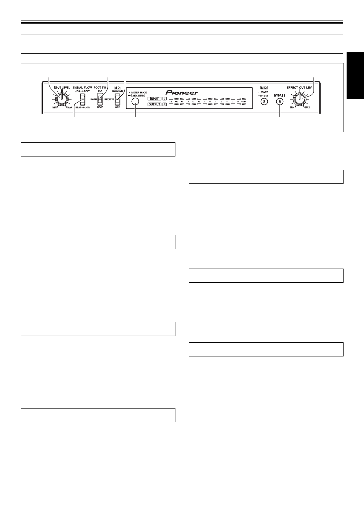
OPERATIONS
INPUT LEVEL FOOT SW MIDI (TRANSMIT/RECEIVE/OFF) EFFECT OUT LEV.
SIGNAL FLOW METER MODE BYPASS
OPERATIONS
English
Adjusting Input Level
Adjust the input level so that the sound is not distorted due
to an excessive input level.
7 Input signals to the input connectors, and rotate the
INPUT LEVEL dial to adjust the level.
¶ Use the METER MODE button to select “input stereo
display” (INPUT, L, R indicators light).
¶ If the proper adjustment cannot be obtained without
rotating the INPUT LEVEL dial to its extreme [MIN] or
[MAX] positions, try changing the position of the rear-panel
IN&OUT LEVEL switch (–10dB / +4dB).
Adjusting Effect Output Level
Adjusts the sound level of the effect applied to the input
sound signal by the beat effect and the digital jog break.
7 Input signals to the input connectors, and rotate the
EFFECT OUT LEV. dial to adjust the effect output level.
¶ Use the METER MODE button to select “output stereo
display” (OUTPUT, L, R indicators light).
¶
When both the BEAT EFFECTS lever switch and the DIGITAL
JOG BREAK lever switch are set to [OFF], the output level is
not changed by turning the EFFECT OUT LEV. dial.
Selecting Signal Flow
¶ When set to the [BEAT] position the foot switch operates to
turn beat effects ON/OFF.
* Use a commercially available switching-type foot switch
with 6.3 mm monaural phone plug.
Selecting the Level Meter Display
This unit’s level meter can be set to display the desired
mode.
7 Press the METER MODE button to select the desired
mode.
¶ Each time the METER MODE button is pressed, the display
switches alternately as follows:
[INPUT] and [OUTPUT] light:
= Input and output level are displayed in monaural.
[INPUT] and [L], [R] light:
= Input level is displayed in stereo.
[OUTPUT] and [L], [R] light:
= Output level is displayed in stereo.
Digital Link Function
Fader Effect Function
When the accessory digital link cable is used to connect
this unit to a DJ mixer (DJM-1000) with digital link support,
send/return connections are completed by a single digital
connection, thus enabling fader effect functions that allow
the DJ mixer’s fader to be used to perform digital jog break.
Select the order in which signal processing occurs (beat
effect or digital jog break)
7 Use the SIGNAL FLOW switch to select the signal
processing order:
¶ When set to the [JOG= BEAT] position, signals are
processed for digital jog break effects first, followed by beat
effects .
¶ When set to the [BEAT= JOG] position, signals are
processed for beat effects first, followed by digital jog break
effects.
Selecting Foot Switch Operation
This effector allows connection of an optional foot switch
(pedal switch) for ON/OFF control of beat effects and digital
jog break effects. Use the foot switch to select the way in
which the foot switch operates.
7 Set the FOOT SW switch to the desired operating
position:
¶ When set to the [JOG] position, the foot switch operates to
turn digital jog break effects ON/OFF.
¶ When set to the [BOTH] position, the foot switch operates to
turn both digital jog break effects and beat effects ON/OFF.
Bypass Function
This function allows signals to be output directly, without
passing through the effects processing circuitry.
7 Press the BYPASS button to make a direct link between
input and output.
¶ When the BYPASS button is pressed, the button flashes and
input signals are output directly, without passing through
the effector circuitry.
¶ When the BYPASS button is flashed, the unit’s controls will
have no effect on the input signals.
19
<DRB1368>
Page 20
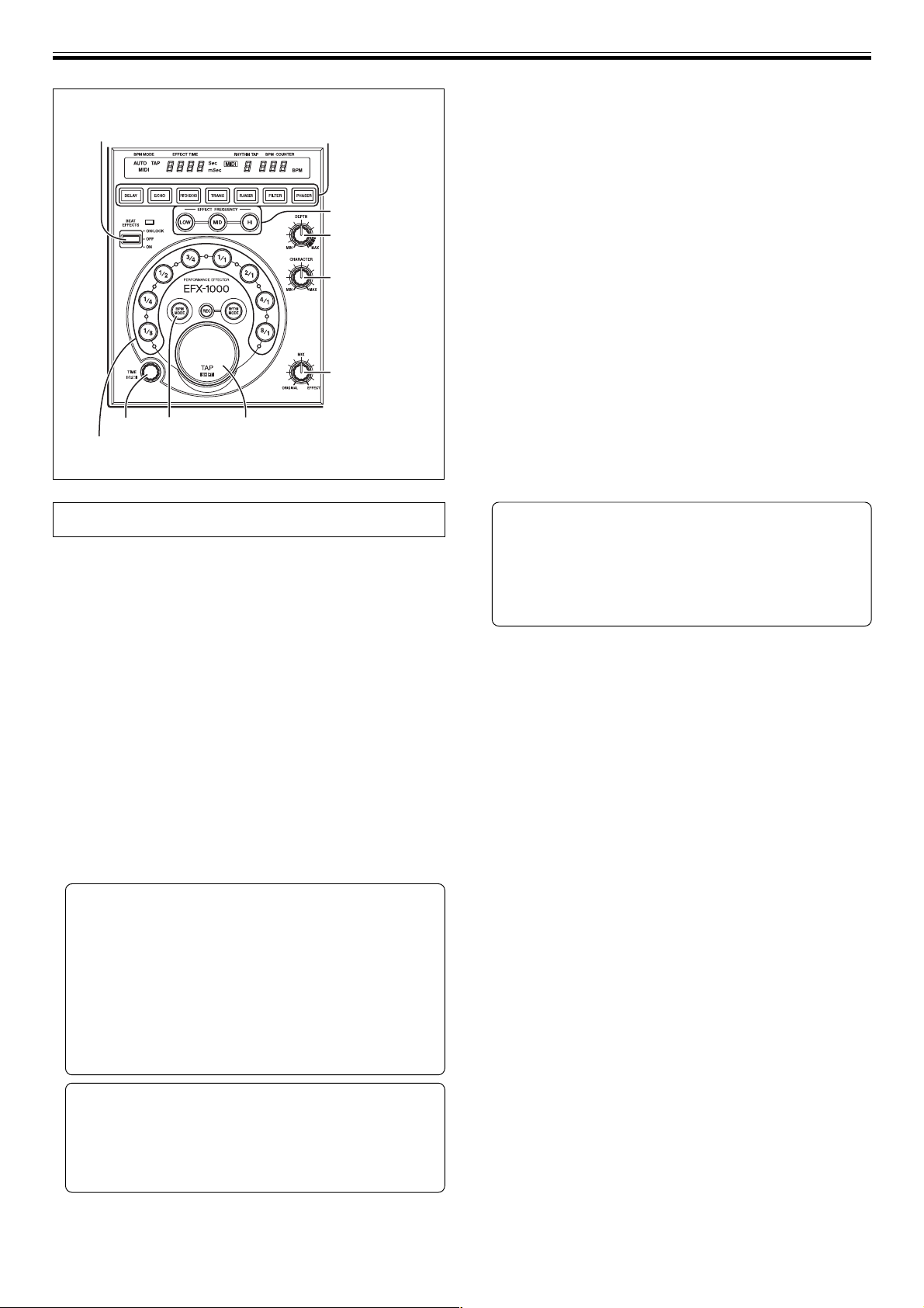
OPERATIONS (Beat Effects [BPM mode])
2) DELAY, ECHO, PITCH ECHO, TRANS,
5) BEAT EFFECTS
1) BPM MODE
TIME
4) 1/8, 1/4, 1/2, 3/4, 1/1, 2/1, 4/1, 8/1
(beat select)
FLANGER, FILTER, PHASER
(beat effect select)
3) EFFECT
FREQUENCY
LOW, MID, HI
DEPTH
CHARACTER
MIX
TAP
Beat Effects [BPM mode]
Since the beat effect time of the beat effect [BPM mode] can
be synchronized in real-time with the BPM (beats per
minute), you can easily generate effects in time with the
rhythm of a live performance.
2. Use the beat effect select buttons to select the desired
effect.
¶ Select from DELAY, ECHO, PITCH ECHO, TRANS,
FLANGER, FILTER, or PHASER.
¶ The selected effect button flashes.
¶ See pages 12, 13 regarding each effect.
3. Use the EFFECT FREQUENCY buttons (LOW, MID, HI) to
select the band to which the effect is to be applied.
¶ When a button is pressed, the button’s indicator will light.
¶ Each time a button is pressed, it alternates ON/OFF.
4. Press one beat select button to select the beat with
which the effect is to be synchronized.
¶ Select from 1/8, 1/4, 1/2, 3/4, 1/1, 2/1, 4/1, or 8/1.
¶ The selected beat button lights.
¶ When a beat select button is pressed, the corresponding
effect time is automatically set.
Example: when BPM is 120,
1/1 = 500 ms
3/4 = 375 ms
1/2 = 250 ms
¶ When the beat select button is pressed and the TAP button
is held down, BPM is automatically set from the effect time.
Manual Input of Effect Time Using the TIME Dial
Normally, the effect time is automatically set when a
beat select button is pressed. However, the effect time
can be set as desired using the TIME dial.
¶ When the effect time is changed, the beat select button
lights for the beat automatically set in correspondence to
the new effect time.
1. Press the BPM MODE button to select the BPM (beatsper-minute) measurement mode.
AUTO: BPM is measured automatically from the input music
source.
MIDI: BPM is measured automatically based on the MIDI timing
clock.
TAP: BPM is input manually by tapping on the TAP button.
¶ When power is first turned ON, the mode defaults to AUTO.
¶ The selected mode is shown by the BPM mode indicator.
¶ In the event the input signal cannot be counted properly,
the BPM COUNTER flashes.
¶ The measurement range in the AUTO mode is 70-180 BPM.
Correct measurement may not be possible depending on
the music track; in this event, input the tempo manually
using the TAP mode.
[Manual BPM input using the TAP button]
When the TAP button is tapped two or more times in
time with the beat (quarter notes), the average value
of the intervals is used to set BPM.
¶ When BPM is set to AUTO or MIDI mode, pressing the TAP
button changes the BPM measuring mode to the TAP mode,
and the unit measures the intervals at which the TAP button
is struck.
¶ When BPM is set with the TAP button, the beat select
button [1/1] is selected and the time of 1 beat (quarter
notes) is set to the effect time.
5. Pull the BEAT EFFECTS lever switch to ON to appy the
effect.
When pushed away from you to the [ON/LOCK] position:
The switch is locked on, so that the effect continues to be
applied even if you remove your hand from the lever. To stop
the effect, return the lever to the middle position [OFF].
When pulled toward you to the [ON] position:
The effect is applied only while the lever is pulled to the [ON]
position; when the lever is released, it returns automatically to
the middle [OFF] position. Use this function when you wish to
alternate rapidly between ON and OFF.
DEPTH dial
Set to the center center indent position for standard effect sounds.
For more information regarding the change in parameter 1 in
response to DEPTH dial rotation, see pages 12, 13, 15.
CHARACTER dial
Set to the center center indent position for standard effect sounds.
For more information regarding the change in parameter 2 in
response to CHARACTER dial rotation, see pages 12, 13, 15.
MIX dial
Use to adjust the mixing balance of original and effect sounds. Set
to the center indent position for standard effect sounds.
[Manual BPM input using the TIME dial]
BPM can be directly set by turning the TIME dial when
the TAP button is held down.
¶ BPM can be set in 0.1 increments by pressing the BPM MODE
button and turning the TIME dial while holding down the TAP
button. Only decimal values are shown at this time.
20
<DRB1368>
Page 21
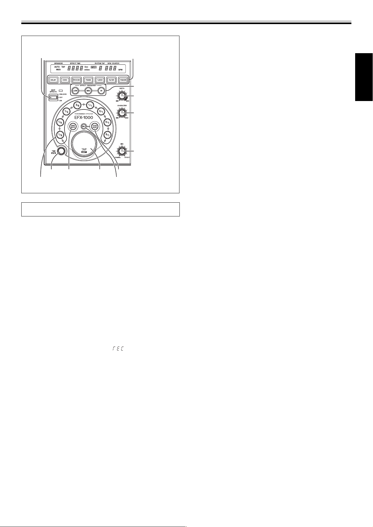
2) DELAY, ECHO, PITCH ECHO, TRANS,
7) BEAT EFFECTS
TIME
6) 1/8, 1/4, 1/2, 3/4, 1/1, 2/1, 4/1, 8/1
(beat select)
FLANGER, FILTER, PHASER
(beat effect select)
BPM MODE 1) RHYTHM MODE
5) TAP
3) EFFECT
FREQUENCY
LOW, MID, HI
DEPTH
CHARACTER
MIX
4) Rhythm REC
OPERATIONS (Beat Effects [RHYTHM mode])
6. Select one of the beat select buttons to establish the
overall time for the input rhythm.
¶ The overall time for the input rhythm will be multiplied in
response to the selected button.
¶ Select from 1/8, 1/4, 1/2, 3/4, 1/1, 2/1, 4/1, or 8/1.
¶ The selected beat button lights.
7. Pull the BEAT EFFECTS lever switch to ON to appy the
effect.
When pushed away from you to the [ON/LOCK] position:
The switch is locked on, so that the effect continues to be
applied even if you remove your hand from the lever. To stop
the effect, return the lever to the middle position [OFF].
When pulled toward you to the [ON] position:
The effect is applied only while the lever is pulled to the [ON]
position; when the lever is released, it returns automatically to
the middle [OFF] position. Use this function when you wish to
alternate rapidly between ON and OFF.
¶ If the Rhythm REC button is pressed during the rhythm
mode, the input rhythm will be cleared and rhythm input
mode is once again enabled.
DEPTH dial
Set to the center center indent position for standard effect sounds.
For more information regarding the change in parameter 1 in
response to DEPTH dial rotation, see pages 12, 13, 15.
English
Beat Effects [RHYTHM mode]
The beat effects [RHYTHM mode] function allows you to
create a variety of effects synchronized with your own
input rhythm.
1. Use the RHYTHM MODE button to set to rhythm mode.
¶ The RHYTHM MODE button lights.
2. Use the beat effect select buttons to select the desired
effect.
¶ Select from DELAY, ECHO, PITCH ECHO, TRANS,
FLANGER, FILTER, or PHASER.
¶ The selected effect button flashes.
¶ See pages 12, 13 regarding each effect.
3. Use the EFFECT FREQUENCY buttons (LOW, MID, HI) to
select the band to which the effect is to be applied.
¶ When a button is pressed, the button’s indicator will light.
¶ Each time a button is pressed, it alternates ON/OFF.
4. Press rhythm REC button to set to REC mode.
¶ The BPM display will indicate “ ”.
¶ If no rhythm has been input, the unit will automatically
enter the REC mode in step 1.
5. Input the desired rhythm using the TAP button.
¶ Input taps will be recognized as a tempo when occurring at
intervals of less than 2 seconds. Up to 8 taps can be input.
¶ The counted taps (RHYTHM TAP) will be shown in the
display.
¶ During rhythm input, the beat select button [1/1] will be
selected.
CHARACTER dial
Set to the center center indent position for standard effect sounds.
For more information regarding the change in parameter 2 in
response to CHARACTER dial rotation, see pages 12, 13, 15.
MIX dial
Use to adjust the mixing balance of original and effect sounds. Set
to the center indent position for standard effect sounds.
21
<DRB1368>
Page 22
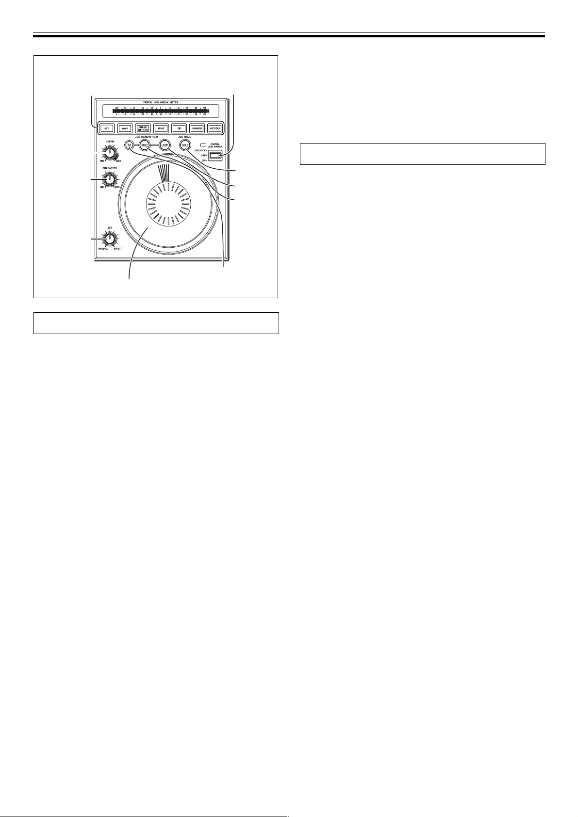
OPERATIONS (Digital Jog Break)
1) JET, WAH, PHASE SHIFTER,
RING, ZIP, HUMANIZER, VOCODER
(Jog effect select)
2) DIGITAL JOG BREAK
MIX dial
Use to adjust the mixing balance of original and effect sounds. Set
to the center indent position for standard effect sounds.
HOLD Function
When the HOLD button is pressed and lit, the effect generated by
the rotation of the Jog dial continues when the dial rotation stops.
DEPTH
CHARACTER
MIX
Jog memory (M)
Jog dial
HOLD
LOOP
SINGLE
Digital Jog Break
Since the digital jog break can continuously change the
parameters of each effect generated by rotating the Jog
dial, the effects can be controlled like a musical instrument.
Further, by using the jog memory function, the continuously
changing effect sound can be stored in memory, and later
played back by pressing one of the JOG MEMORY PLAY
buttons (SINGLE or LOOP).
1. Use the Jog effect select buttons to select the desired
effect.
¶ Select from JET, WAH, PHASE SHITER, RING, ZIP,
HUMANIZER, or VOCODER.
¶ The selected Jog effect button flashes.
¶ See page 14 regarding each effect.
2. Set the DIGITAL JOG BREAK lever switch to ON and
turn the Jog dial.
[DIGITAL JOG BREAK Lever switch operation]
When pushed away from you to the [ON/LOCK] position:
The switch is locked on, so that the effect continues to be
applied even if you remove your hand from the lever. To stop
the effect, return the lever to the middle position [OFF].
When pulled toward you to the [ON] position:
The effect is applied only while the lever is pulled to the [ON]
position; when the lever is released, it returns automatically to
the middle [OFF] position. Use this function when you wish to
alternate rapidly between ON and OFF.
¶ Parameter changes caused by rotating the Jog dial are
indicated on the DIGITAL JOG BREAK METER.
Jog Memory
Up to 8 seconds of the digital jog break’s jog dial
movement can be stored in memory, and the effect later
played back at a single touch.
1. Use the Jog effect select buttons to select the desired
effect.
¶ Select from JET, WAH, PHASE SHITER, RING, ZIP,
HUMANIZER, or VOCODER.
¶ The selected Jog effect button flashes.
¶ See page 14 regarding each effect.
2. Set the DIGITAL JOG BREAK lever switch to ON to
monitor the effect.
3. Turn the Jog dial while holding down the Jog memory
button (M).
Turning the Jog dial while the M button is held down starts
memory storage. Effects are stored continues for 8 seconds or
until the M button is released. The SINGLE or LOOP button
lights.
¶ When an effect has already been stored in memory
(SINGLE button and LOOP button are lighted), if a new
effect is stored in memory, the previously stored contents
will be overwritten and the effect data will be erased.
4. Press the SINGLE or LOOP button.
¶ When the SINGLE button is pressed, the button flashes and
the stored effect produced by the jog dial movement is
played back one time.
¶ When the LOOP button is pressed, the button flashes and
the stored effect produced by the jog dial movement is
played back repeatedly. Press the LOOP button once again
to stop the effect playback.
¶ Jog dial operation stored in memory can be reproduced
even when the type of effect is subsequently changed.
DEPTH dial
Set to the center center indent position for standard effect sounds.
For more information regarding the change in parameter 1 in
response to DEPTH dial rotation, see pages 14, 15.
CHARACTER dial
Set to the center center indent position for standard effect sounds.
For more information regarding the change in parameter 2 in
response to CHARACTER dial rotation, see pages 14, 15.
22
<DRB1368>
Page 23
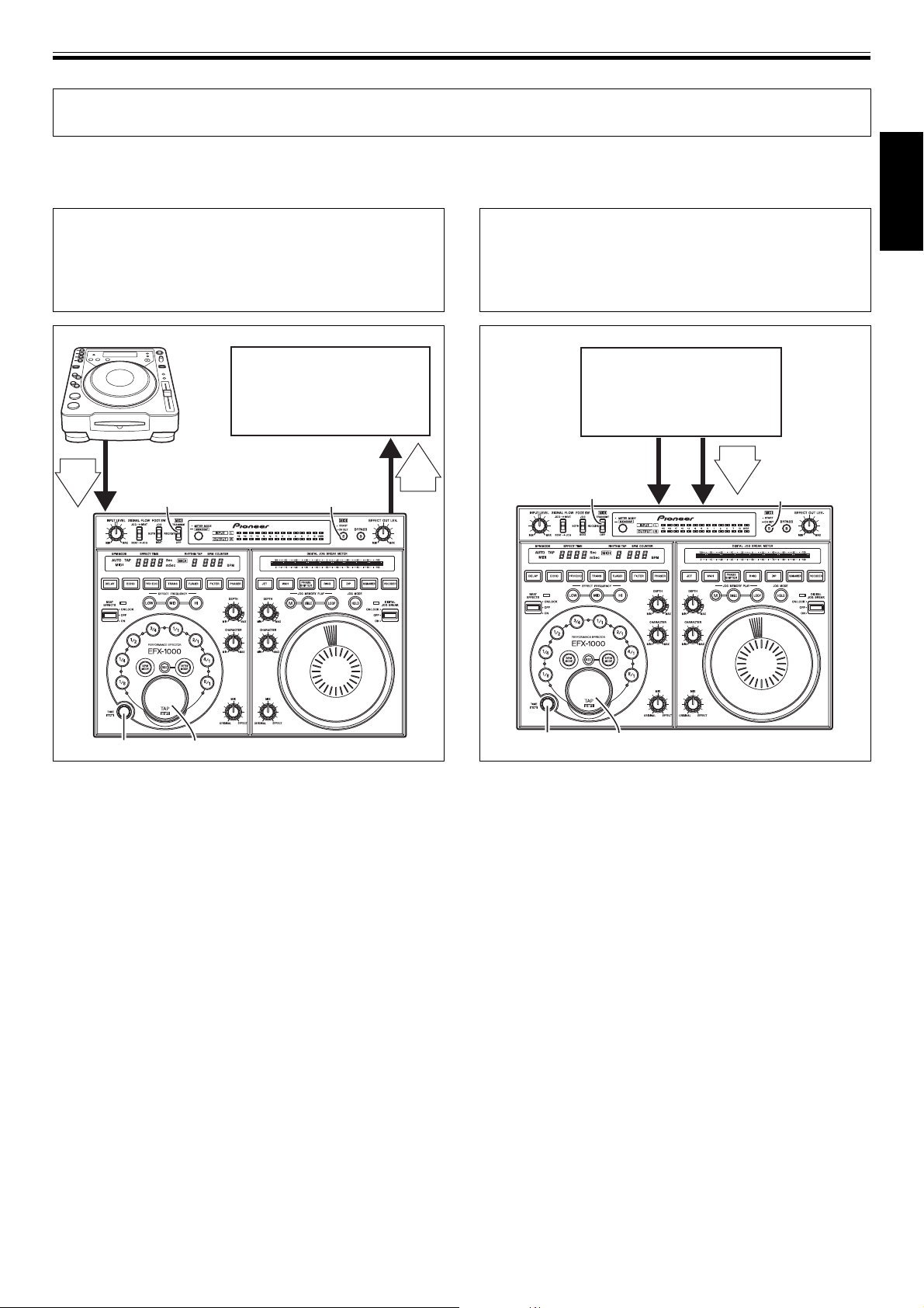
MIDI SETTINGS
MIDI SETTINGS
MIDI (Musical Instrument Digital Interface) is a standard protocol designed to allow exchange of information between electronic
instruments and/or computers. A MIDI cable is used to connect two appliances equipped with MIDI connectors, thus allowing data to be
exchanged between the two appliances. The EFX-1000 uses MIDI to send and receive operation and BPM data (timing clock).
Synchronizing an external
sequencer to an audio signal, or
using EFX-1000 operation data to
operate an external sequencer
DJ CD player
MIDI sequencer
OUT
BPM
=120
Audio
MIDI TRANSMIT/
RECEIVE/OFF
MIDI
MIDI START/
CH SET
OUTIN
IN
BPM
=120
To synchronize beat effects to
external sequencer, or use an
external sequencer to operate the
EFX-1000
MIDI sequencer
MIDI TRANSMIT/
RECEIVE/OFF
Audio
OUTOUT
MIDI
BPM
=120
MIDI START/
ININ
CH SET
English
TIME TAP
EFX-1000
1. Use a commercially available MIDI cable to connect the
EFX-1000’s MIDI OUT connector and the MIDI
sequencer’s MIDI IN connector.
¶ The MIDI sequencer’s sync mode should be set to slave.
¶ MIDI sequencers which do not support MIDI timing clock
cannot be synchronized.
2. Set MIDI switch to [TRANSMIT] position.
¶ Sync cannot be performed in the case of tracks whose BPM
values cannot be measured stably.
¶ Timing clock is also output for BPM values set by using the
TAP mode.
3. Press the MIDI START/CH SET button.
¶ MIDI timing clock output range is 40-250 BPM.
[Setting TRANSMIT MIDI channel]
The TRANSMIT channel can be set and recorded in memory
separately from the RECEIVE channel.
1. Set MIDI switch to [TRANSMIT] position.
2. In this condition, hold the MIDI START/CH SET button
depressed.
¶ The MIDI indicator will flash and the setting mode will be
enabled.
3. Rotate the TIME dial to select MIDI channel.
4. Press the MIDI START/CH SET button.
¶ The MIDI channel will be recorded, and the unit will leave
the setting mode.
NOTE:
It may not be possible to set BPM correctly with some tracks.
TIME TAP
EFX-1000
1. Use a commercially available MIDI cable to connect the
MIDI sequencer’s MIDI OUT connector to the EFX-1000’s
MIDI IN connector.
¶ Adjust controls for optimum instrument input/output levels.
¶ Set all effect switches to OFF.
¶ Set BYPASS switch to OFF.
2. Set the MIDI switch to the [RECEIVE] position.
¶ The MIDI OUT/THRU connector will throughput (output) the
same signal that was input.
3. Start the MIDI sequencer.
¶ Even during use of sequencer control, the EFX-1000 can be
controlled directly if desired, but depending on the volume,
the set parameter values may jump at the instant an
operation is performed, so caution is needed.
¶ The range that the MIDI timing clock can accept is 40-250
BPM.
[Setting the RECEIVE MIDI channel]
The RECEIVE channel can be set and recorded in memory
separately from the TRANSMIT channel.
1. Set MIDI switch to [RECEIVE] position.
2. In this condition, hold the MIDI START/CH SET button
depressed.
¶ The MIDI indicator will flash and the setting mode will be
enabled.
3. Rotate the TIME dial to select the MIDI channel, then
press the TAP button to confirm.
NOTE:
If the MIDI sequencer’s BPM is set in 0.1 units, it may not match the
BPM display on the EFX-1000.
<DRB1368>
23
Page 24
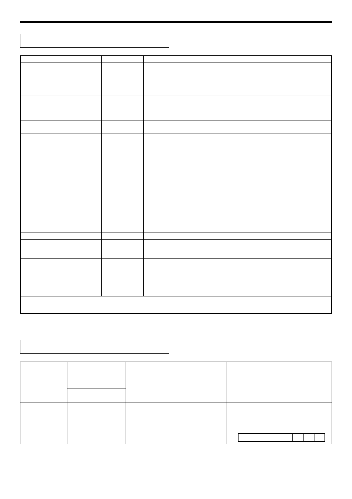
MIDI SETTINGS
MIDI Implementation Chart
Function
Basic channel: When power ON
Settable range
When power ON
Mode: Message
Replacement
Note number:
Sound range
Velocity: Note ON
Note OFF
After touch: By Key
By Channel
Pitch Bender:
12, 44
13, 45
16, 48
17, 49
64
66
Control change: 67
69
80
81
82
83
91
92
Program change: setting range
Exclusive:
Song position
Common: Song select
Tune
Real time: Clock
Command
Local ON/OFF
Other: All Note/OFF
Active sensing
Reset
Comments:
Transmit
1-16
1-16
Mode 3
✕
✕
✕
✕
✕
✕
✕
✕
‡
‡
‡
‡
‡
‡
‡
‡
‡
‡
‡
‡
‡
‡
‡
✕
✕
✕
✕
‡
‡
✕
✕
✕
✕
Receive
1-16
1-16
Mode 3
✕
✕
✕
✕
✕
✕
✕
✕
‡
‡
‡
‡
‡
‡
‡
‡
‡
‡
‡
‡
‡
‡
‡
✕
✕
✕
✕
‡
✕
✕
✕
✕
✕
Comments
Stored in memory
Beat select time parameter (MSB, LSB)
Time parameter (MSB, LSB)
JOG parameter (MSB, LSB)
Rhythm parameter 1 (MSB, LSB)
Effect ON/OFF
Frequency select
Rhythm parameter 2
Beat Operation Mode
VR parameter 1
VR parameter 2
VR parameter 3
VR parameter 4
VR parameter 5
VR parameter 6
Transmit: start/stop
Mode 1: Omni, ON, Poly Mode 2: Omni, ON, Mono ‡: Yes
Mode 3: Omni, OFF, Poly Mode 4: Omni, OFF, Mono ✕: No
Control Change (CC) Table
Function
Effect type
switching
Effect ON/OFF
24
<DRB1368>
EFX-1000 Operation
Signal flow change
Beat effect select
Digital jog break
Effect select
Beat effect (ON/OFF)
Digital jog break
Effect (ON/OFF)
Message
(Command)
ProgramChange
Hold 1
Format (Hex)
Cn pc
Bn 40 0b
Comments
See program change below.
Sets effect ON/OFF.
b: Effect ON/OFF (ON = 1)
Bit0 JOG
Bit1 BEAT
MSB LSB
000000
BEAT JOG
Page 25
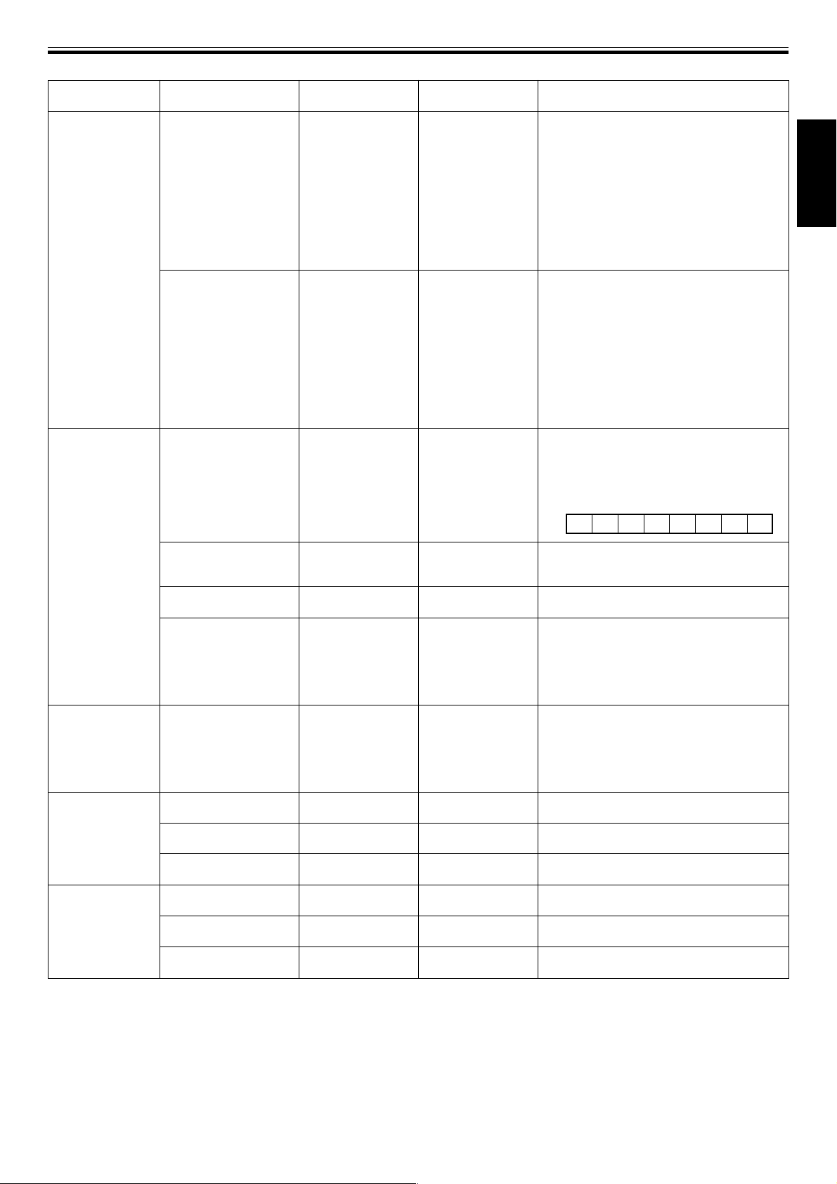
MIDI SETTINGS
Function
Effect time
operation
EFX-1000 Operation
Beat select
TIME dial
Effect frequency select
Message
(Command)
Effect Control 1
Effect Control 2
sostenuto
Format (Hex)
Bn 0c MSB
Bn 2c LSB
Bn 0d MSB
Bn 2d LSB
Bn 42 0b
Comments
Sets effect time.
Setting range (unit: mSec)
DELAY, ECHO, PITCH ECHO: 1-16000
TRANS: 10-16000
FLANGER, FILTER, PHASER: 5-16000
When 5-16000 are transmitted for FLANGER,
FILTER, or PHASER, EFX-1000 internally
multiplies value by x2, so as to operate at 10-
32000.
* On receive side, search is performed for
beginning of effect cycle.
Sets effect time.
Setting range (unit: mSec)
DELAY, ECHO, PITCH ECHO: 1-16000
TRANS: 10-16000
FLANGER, FILTER, PHASER: 5-16000
When 5-16000 are transmitted for FLANGER,
FILTER, or PHASER, EFX-1000 internally
multiplies value by x2, so as to operate at 10-
32000.
* On receive side, search is not performed
for beginning of effect cycle.
Sets frequency range subjected to effect
b: frequency range (ON = 1)
Bit0 LOW
Bit1 MID
Bit2 HI
MSB LSB
00000HIMID
LOW
English
Beat operation
Jog operation
Beat volume
Jog volume
Rhythm TAP
(rhythm time)
Rhythm TAP
(rhythm no.)
BPM mode SW
Rhythm mode SW
Rhythm REC
Jog dial
Beat effect DEPTH
Beat effect CHARACTER
Beat effect MIX
Digital jog break DEPTH
Digital jog break
CHARACTER
Digital jog break MIX
General Purpose
Controller 2
soft pedal
hold 2
General Purpose
Controller 1
Effect 1 Depth
General Purpose
Controller 5
General Purpose
Controller 6
Effect 2 Depth
General Purpose
Controller 7
General Purpose
Controller 8
Bn 11 MSB
Bn 31 LSB
Bn 43 dd
Bn 45 dd
Bn 10 MSB
Bn 30 LSB
Bn 5B dd
Bn 50 dd
Bn 51 dd
Bn 5C dd
Bn 52 dd
Bn 53 dd
Sets tap time interval for rhythm effect.
Setting range (unit: mSec)
1-2000
Sets tap number for rhythm effect.
Setting range: 1-8
Changes Beat operating mode.
1=BPM mode
2=Rhythm mode
During rhythm mode, if rhythm mode is set
again, the recorded rhythm effect will be
canceled and new rhythm data can be input.
Sets jog dial movement.
Setting range: 0-2160
Jog center position is considered 1080; when
dial is rotated clockwise, changes to
maximum 2160; when dial is rotated
counterclockwise, changes to minimum 0.
Sets beat DEPTH value.
Setting range: 0-127
Sets beat CHARACTER value.
Setting range: 0-127
Sets beat MIX value.
Setting range: 0-127
Sets Jog DEPTH value.
Setting range: 0-127
Sets jog CHARACTER value.
Setting range: 0-127
Sets jog MIX value.
Setting range: 0-127
25
<DRB1368>
Page 26
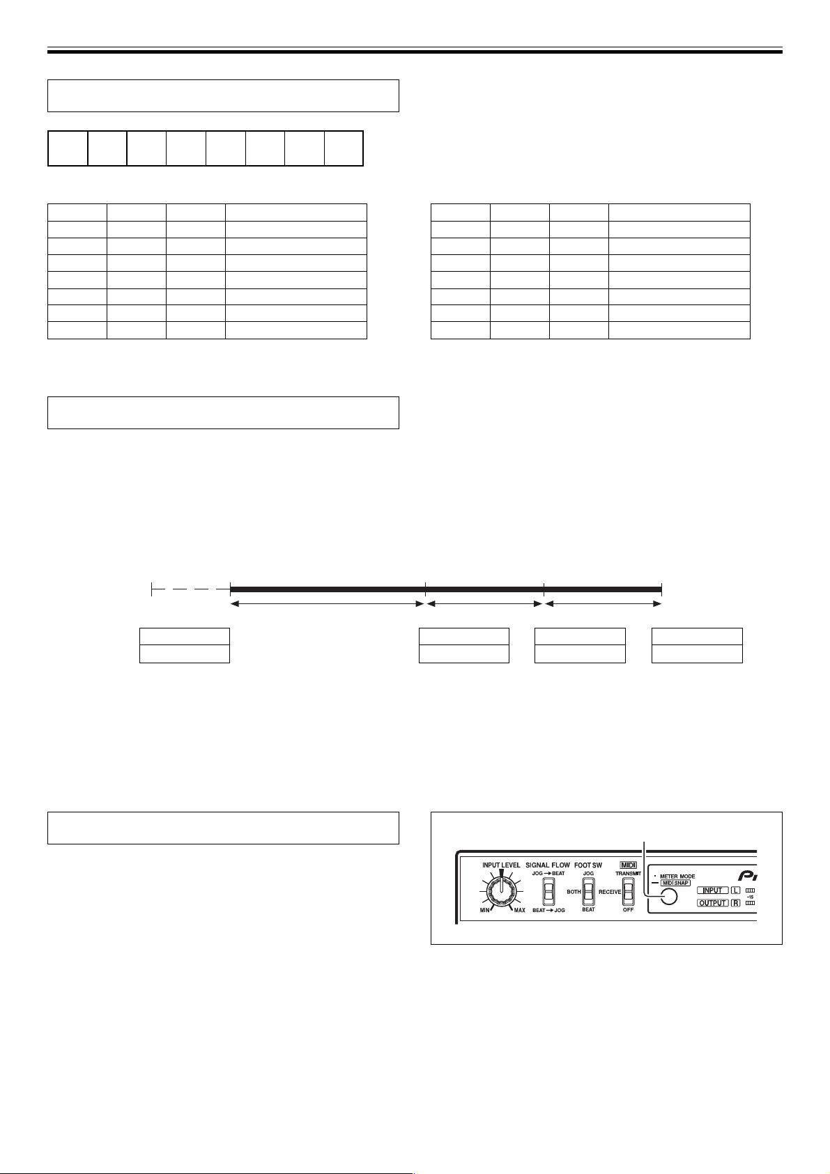
MIDI SETTINGS
Program Change
MSB LSB
SIGNAL
FLOW
0 JOG1BEAT2 BEAT0BEAT1 JOG2
JOG0
¶ SIGNAL FLOW
0 = BEAT EFFECTS = JOG BREAK
1 = JOG BREAK = BEAT EFFECTS
¶ BEAT EFFECTS
BEAT2
0
0
0
1
1
1
1
Use general purpose 8 for setting filters
BEAT1
0
1
1
0
0
1
1
BEAT0
1
0
1
0
1
0
1
DELAY
ECHO
PITCH ECHO
TRANS
FLANGER
FILTER
PHASER
¶ JOG BREAK
JOG2
0
0
0
1
1
1
1
JOG1
JOG0
0
1
1
0
0
1
1
1
0
1
0
1
0
1
JET
WAH
PHASE SHIFTER
RING
ZIP
HUMANIZER
VOCODER
About Rhythm Effects
(Example shown is 3 rhythms)
During TRANSMIT:
Each time rhythm TAP is struck, data is transmitted in the order rhythm parameter 2 (rhythm No.) and rhythm parameter 1
(rhythm time).
Effector operation
TAP TAP TAP TAPRHYTHM MODE button
time 1 time 2 time 3
MIDI data
Beat section
Rhythm mode
Rhythm No. 1
time 1
Rhythm No. 2
time 2
Rhythm No. 3
time 3
During RECEIVE:
¶ During beat effect, if beat operation mode (rhythm mode) is received, the rhythm effect function is enabled.
Thereafter, if the first time rhythm No. 1, time 1, rhythm No. 2, time 2, rhythm No. 3, time 3 are transmitted in that order,
the effector continues to operate in response to the received rhythm.
¶ During rhythm effect, if the beat operation mode (BPM mode) is transmitted, the function returns to beat effect.
Snapshot
Once the effector is set to a target value, a snapshot of that
state can be taken. When snapshot is used, all commands
for control change are transmitted at once.
When setting [TRANSMIT], hold the METER MODE/MIDI
SNAP button depressed to transmit the snapshot. When
this is done the MIDI indicator will flash.
METER MODE/MIDI SNAP
26
<DRB1368>
Page 27
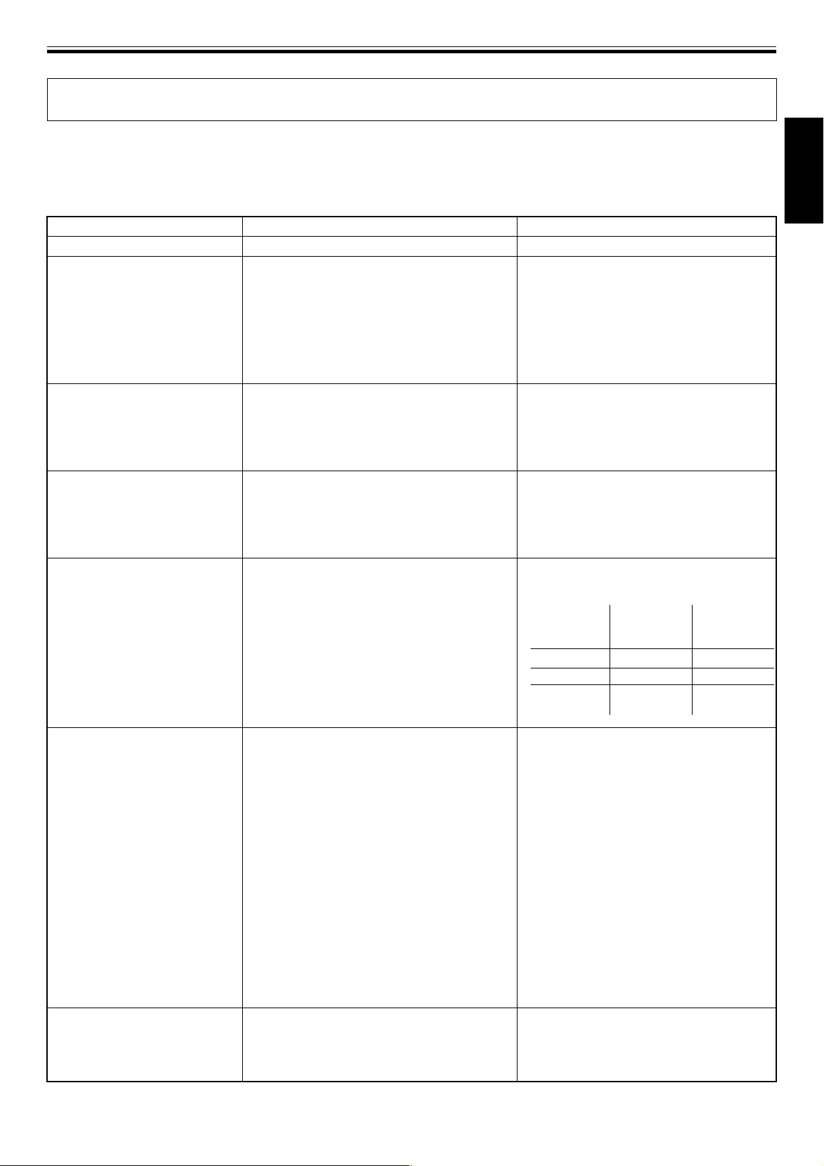
OTHER (TROUBLESHOOTING)
TROUBLESHOOTING
Incorrect operations are often mistaken for trouble and malfunctions. If you think there is something wrong with this
component, check the points below. Sometimes the trouble may originate from another component. Thus, also check the
other electrical appliances also in use.
If the trouble cannot be rectified even after checking the following items, contact your dealer or nearest PIONEER service
center.
Symptom Probably cause Remedy
No power
No sound, or too low
Analog inputs aren’t output
Digital signals aren’t output.
When set to BYPASS, analog
signals aren’t output.
÷ Power cord isn’t connected.
÷ Connection cords are loose or aren’t con-
nected properly.
÷ Connector terminals and plugs are dirty.
÷ Input level is set too low.
÷ Effect output level is set too low.
÷ A digital or EFX LINK input is connected.
When analog and digital inputs are connected
simultaneously, the digital input is given
priority.
÷ The DJ mixer (DJM-1000) connected by EFX
LINK has its effecter link set to ON (EFX LINK).
÷ EFX LINK is connected to DJ mixer (DJM-
1000) via digital link cable.
÷ The digital output fs setting does not match
the connected component.
÷ No analog inputs are connected.
Even if a digital input or EFX LINK is
connected, analog inputs are output as analog
during BYPASS mode.
÷ Connect power cord to outlet.
÷ Connect properly.
÷ Wipe away dirt and soil.
÷ Rotate INPUT LEVEL dial toward right
([MAX] direction).
÷ Try setting IN&OUT LEVEL switch to the
opposite position.
÷ Rotate EFFECT OUT LEV. dial toward right
([MAX] direction).
÷ Cancel the EFX LINK, and disconnect any
digital input with priority over analog
inputs.
The order of priority of inputs is:
EFX LINK > Digital input > Analog input.
÷ If EFX LINK is connected to DJ mixer (DJM-
1000) via digital link cable, ordinary digital
signals are not output.
Disconnect the digital link cable.
÷ Set the digital output fs to match the
connected component.
÷ Use analog signals for input. Or use digital
output. Outputs when BYPASS is selected
are as follows:
Input
connection
conditions
Analog only
Digital only
Analog &
digital
Analog output
Analog source
(no output)
Analog source
Digital output
Analog source
Digital source
Digital source
English
Effect sounds aren’t applied.
No effect sound is heard when
beat effects are applied.
÷ The lever switch is set to [OFF].
÷ MIX dial is set to [MIN].
÷ DEPTH dial is set to [MIN].
÷ EFFECT OUT LEV. dial is set to [MIN].
÷ BYPASS button is ON.
÷ EFFECT FREQUENCY indicators (HI, MID,
LOW) are all off (during use of TRANS,
FLANGER, FILTER, or PHASER effects).
÷ Some combinations of effects may have weak
results. Particularly, some combinations of
beat effects and digital jog break may sound
weak.
÷ EFFECT FREQUENCY indicators (HI, MID, LOW)
are all off (during use of DELAY, ECHO, PITCH
ECHO effects).
÷ Either hold lever switch in [ON] position, or
set to [ON/LOCK].
÷ Rotate MIX dial toward the right ([MAX]
direction).
÷ Rotate DEPTH dial toward the right ([MAX]
direction).
÷ Rotate EFFECT OUT LEV. dial toward the
right ([MAX] direction).
÷ If BYPASS indicator is flashed, no effects
will be output. Press BYPASS so that the
indicator goes out.
÷ If EFFECT FREQUENCY indicators are all off,
only the original sound will be output. Press
the button corresponding to the frequency
band to which you wish to apply effects (the
button’s indicator will light).
÷ Try setting SIGNAL FLOW switch to the
opposite position (reverse order of signal
processing for beat effects and digital jog
break).
÷ If EFFECT FREQUENCY indicators are all off,
no effect sound will be output. Press the
button corresponding to the frequency band
to which you wish to apply effects (the
button’s indicator will light).
27
<DRB1368>
Page 28

OTHER (SPECIFICATIONS)
Symptom Probably cause Remedy
When a foot switch is connected,
effects are applied even without
pressing the foot switch.
Effect sounds are distorted.
Can’t use EFX LINK function
Can’t use the BPM sync function.
Echo sounds are output
continuously
BPM doesn’t count tempo in
AUTO mode.
BPM count is strange.
MIDI sequencer isn’t
synchronized.
÷ Foot switch’s logic is reversed (the effector
applies effects when the foot switch is
depressed for LOW level).
÷ Input level is too high.
÷ Effect output level is too high.
÷ Effect settings are too high (When the DEPTH
dial is set near its [MAX] position, it may have
the effect of raising the volume level.)
÷ The digital link cable is not connected.
÷ The connected component is not supported.
÷ The DJ mixer’s settings are incorrect
÷ DJ mixer is not connected for EFX LINK.
÷ A DJ CD player with digital link support is not
connected to the DJ mixer.
÷ The BPM measurement mode is not set to
[AUTO].
÷ During echo effect, if DEPTH dial is set to
[MAX] and BEAT EFFECTS lever switch is
moved from [ON] to [OFF], the feedback
sound dies not attenuate, producing a hold
delay effect.
÷ Input level is too high, or too low.
÷ Some tracks have tempos that prevent them
from being measured automatically. (Automatic
measurement range is 70-180 BPM).
÷ The MIDI sequencer’s sync mode is not set to
“slave”.
÷ The connected MIDI sequencer is not
supported.
÷ Use a foot switch with logic matching that
of the effector.
÷ Rotate INPUT LEVEL dial toward left ([MIN]
direction).
÷ Try setting IN&OUT LEVEL switch to the
opposite position.
÷ Rotate EFFECT OUT LEV. dial toward left
([MIN] direction).
÷ Rotate DEPTH dial toward left ([MIN]
direction).
÷ Connect the digital link cable to a DJ mixer
(with digital link support)
÷ Set the DJ mixer for EFX LINK.
÷ Connect the DJ CD player and DJ mixer via
digital link.
÷ Set the DJ effector’s BPM mode to [AUTO].
÷ Rotate DEPTH dial toward the left ([MIN]
direction).
÷ Rotate INPUT LEVEL dial so that the input
level meter shows around 0 dB.
÷ Set to manual mode and input (TAP) the
tempo manually (P.20)
÷ Set MIDI sequencer’ s sync mode to
“slave.”
÷ A MIDI sequencer without MIDI timing
clock cannot be synchronized.
÷ This component may fail to operate properly due effects from static electricity or other causes. In this event, try
disconnecting the power cord and reconnecting it. If this doesn’t solve the problem, consult your dealer or nearest
Pioneer Service Station.
SPECIFICATIONS
1. General
Power supply .......................................... AC 220 V - 240 V, 50/60 Hz
Power consumption .................................................................... 16 W
Operating temperature ................................................ +5°C to +35°C
Relative humidity ...................... 5% to 85% (without condensation)
Weight ......................................................................................... 2.4 kg
Maximum external dimensions
.......................................................... 320 (W) x 234 (D) x 101 (H) mm
2. Audio Unit
Sampling rate ............................................................................ 96 kHz
A/D, D/A Resolution .................................................................. 24 bits
Frequency characteristics ......................................... 20 Hz to 22 kHz
S/N ratio ....................................................................................... 83 dB
Distortion ................................................................................... 0.02 %
Headroom .................................................................................... 19 dB
Input level ................................................... –10 dBV / +4 dBu (22 kΩ)
Output level ............................................................. –10 dBV / +4 dBu
(RCA pin jacks: 1 kΩ, Phone jacks: 1 kΩ)
*–10 dBV / +4 dBu is switchable.
3. Input/Output terminals
Audio line input terminal
RCA pin jacks ................................................................................. 2
Phone jacks (1/4-inch/6.3 mm in diameter) ................................ 2
Audio line output terminal
RCA pin jacks ................................................................................. 2
Phone jacks (1/4-inch/6.3 mm in diameter) ................................ 2
Digital input terminal
RCA pin jack ................................................................................... 1
Digital output terminal
RCA pin jack ................................................................................... 1
EFX LINK connector (mini-DIN) ........................................................ 1
MIDI input terminal (5-pin DIN) ......................................................... 1
MIDI output terminal (5-pin DIN) ...................................................... 1
4. Accessories
Operating instructions ....................................................................... 1
Digital link cable ................................................................................. 1
Power cord .......................................................................................... 1
NOTE:
Specifications and design are subject to possible modification
without notice.
28
<DRB1368>
Page 29
Nous vous remercions pour cet achat d’un produit Pioneer.
Nous vous demandons de lire soigneusement ce mode d’emploi; vous
serez ainsi à même de faire fonctionner l’appareil correctement. Après
avoir bien lu le mode d’emploi, le ranger dans un endroit sûr pour
pouvoir s’y référer ultérieurement.
Dans certains pays ou certaines régions, la forme de la fiche
d’alimentation et de la prise d’alimentation peut différer de celle qui
figure sur les schémas, mais les branchements et le fonctionnement
de l’appareil restent les mêmes. K015 Fr
CARACTÉRISTIQUES
1 Des sons de haute fidélité
La conception à haute fidélité comprend un convertisseur A/N
et N/A à 24 bits (échantillonnage de 96 kHz) et DSP (processeur de signal numérique) à 32 bits, ce qui permet
d’ajouter des effets sans abaisser la qualité du son original.
Une fonction de dérivation à relais a également été adoptée.
2 Effecteur de mesure à 3 bandes
1) Effets de mesure [mode BPM]
Équipé du compteur BPM /effecteur de mesure automatique,
rendu populaire par le EFX-500. Il autorise un traitement des
effets sur les bandes sélectionnées séparément en
synchronisation avec le tempo (BPM) du morceau. Vous avez
ainsi plus de possibilités d’expression qu’avec les effecteurs
conventionnels, agissant sur toutes les bandes.
2) Effets de mesure [mode RHYTHM]
Premier en son genre, cet effecteur rythmique vous permet
d’appliquer des effets en synchronisation avec le rythme
imposé par vous-même. Par l’expression d’une plage bien
plus large d’effets uniques qu’avec les effecteurs de mesures
antérieurs, vous pouvez atteindre un niveau inédit de
performances DJ.
3 Fonction Digital Job Break
La bague Jog autorise un contrôle des effets sonores en
temps réel. Vous pouvez conserver en mémoire jusqu’à 8
secondes de la fonction Jog en vue d’une relecture
automatique. Un maximum de 49 effets sont disponibles
en combinaison avec l’effecteur de mesure.
4 Fonction Entrée/Sortie MIDI
Des signaux MIDI externes (signaux de contrôle et signaux
d’horloge de synchronisation) sont utilisés pour contrôler
l’effecteur et comme moyen d’employer l’effecteur afin de
contrôler un séquenceur ou un autre composant.
TABLE DES MATIÈRES
CARACTÉRISTIQUES ................................................ 29
VÉRIFICATION DES ACCESSOIRES ........................ 29
GUIDE DE DÉMARRAGE RAPIDE
UTILISATION DES EFFETS DE MESURE
[MODE BPM] .............................................................. 30
UTILISATION DES EFFETS DE MESURE
[MODE RYTHME]....................................................... 31
UTILISATION DE LA COUPURE
A JOG NUMÉRIQUE ................................................. 32
UTILISATION DE LA LECTURE À MÉMOIRE JOG ......
AVANT L’UTILISATION
BRANCHEMENTS ...................................................... 33
Panneau de connexion ....................................... 33
Branchements de base ....................................... 34
LES EFFETS ACOUSTIQUES .................................... 36
Effets de mesure .................................................. 36
Coupure par Jog numérique .............................. 38
Paramètres des effets ......................................... 40
LES COMMANDES ET LEURS FONCTIONS ........... 41
Pupitre de commande ......................................... 41
MODES D’UTILISATION
MODES D’UTILISATION ........................................... 44
Réglage du niveau d’entrée ............................... 44
Réglage du niveau de sortie des effets ............. 44
Sélection du parcours des signaux ................... 44
Sélection du fonctionnement de la pédale ....... 44
Sélection d’affichage du décibelmètre.............. 44
Fonction de liaison numérique .......................... 44
Fonction Dérivation ............................................. 44
Effets de mesure [mode BPM] ........................... 45
Effets de mesure [mode RHYTHM].................... 46
Coupure à Jog numérique.................................. 47
Mémoire Jog ........................................................ 47
RÉGLAGES MIDI
RÉGLAGES MIDI ........................................................ 48
Synchronisation d’un séquenceur externe à un
signal audio, ou emploi des données du EFX-1000
pour contrôler un séquenceur externe ................ 48
Synchronisation des effets de mesure à un
séquence externe, ou emploi d’un séquenceur
externe pour contrôler le EFX-1000 ..................... 48
Tableau de mise en œuvre MIDI .......................... 49
Tableau de changement de contrôle (CC) ........ 49
Changement de programme .............................. 51
A propos des effets de rythme........................... 51
Instantané ............................................................. 51
32
Français
5 Fonction Digital Link
Diverses fonctions peuvent être exécutées en faisant appel au
câble de liaison numérique spécialisé afin de raccorder cet
appareil à un mixeur DJ Pioneer (DJM-1000) qui prend en
compte la liaison numérique.
6 Entrée/Sortie numérique
L’appareil est doté de connecteurs numériques IN/OUT
(entrée/sortie) à échantillonnage 24 bits/96 kHz, ce qui
autorise des utilisations pour créations en studio et
d’autres applications, exigeant des sons de haute qualité.
AUTRES INFORMATIONS
GUIDE DE DÉPANNAGE ........................................... 52
FICHE TECHNIQUE .................................................... 54
SCHÉMA DE CÂBLAGE........................................... 160
VÉRIFICATION DES
ACCESSOIRES
Mode d’emploi ....................................................................... 1
Câble de liaison numérique .................................................. 1
Cordon d’alimentation ......................................................... 1
29
<DRB1368>
Page 30
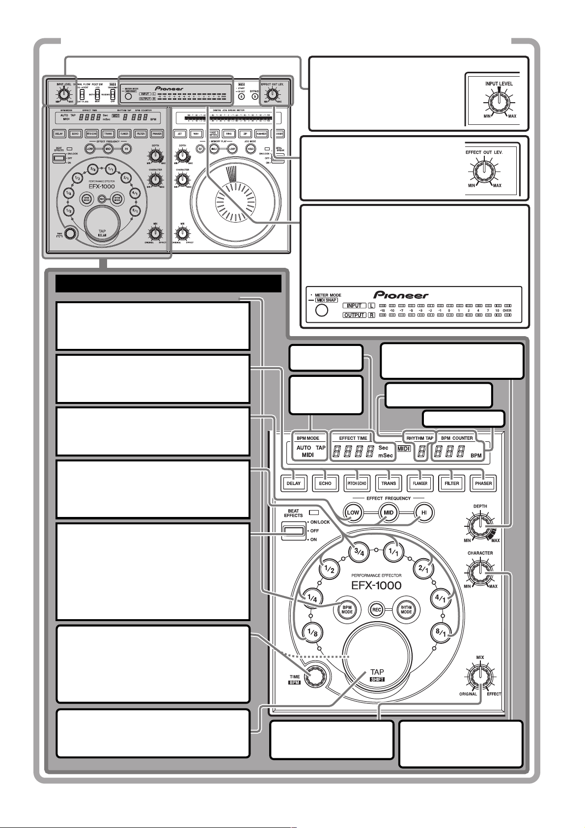
GUIDE DE DÉMARRAGE RAPIDE (1/3)
Réglage du niveau d’entrée
Fournissez des signaux aux
connecteurs d’entrée et ajustez
la bague INPUT LEVEL.
Réglage du niveau de sortie
d’effet
Tournez la bague EFFECT OUT LEV.
pour ajuster le niveau de sortie
d’effet.
Changement du mode d’affichage du décibelmètre
À chaque poussée sur le bouton METER MODE,
l’affichage du décibelmètre alterne comme suit:
÷ Allumage de INPUT, OUTPUT: affichage d’entrée et
de sortie monaurale.
÷ Allumage de INPUT, L, R: affichage d’entrée stéréo.
Allumage de OUTPUT, L, R
UTILISATION DES EFFETS DE MESURE [MODE BPM]
÷
1. Sélectionnez le mode de mesure BPM.
Appuyez sur la touche BPM MODE de sorte
qu’elle s’allume de même que le témoin de
mode souhaité (AUTO/MIDI/TAP).
Afficheur de
2. Sélectionnez le type d’effet.
Appuyez sur la touche DELAY, ECHO, PITCH
ECHO, TRANS, FLANGER, FILTRER ou
PHASER et la touche actionnée clignote.
durée d’effet
Voyants de
mode de
mesure BPM
3. Sélectionnez la plage sonore de l’effet.
Appuyez sur la touche de la fréquence (LOW,
MID, HI) qui doit être affectée par l’effet de
mesure et le témoin correspondant s’allume.
Bague de profondeur (DEPTH)
Elle définit le paramètre 1 de
chaque effet.
: affichage de sortie stéréo.
Afficheur RHYTHM
TAP
Compteur BPM
4. Sélectionnez la mesure avec laquelle
l’effet doit être synchronisé.
Appuyez sur un sélecteur de mesure (1/8, 1/4,
1/2, 3/4, 1/1, 2/1, 4/1 ou 8/1) et le témoin du
sélecteur actionné s’allume.
5. Appliquez un effet.
Déplacez le levier vers vous (position ON) pour
lancer l’opération; relâchez le levier et il revient
en position centrale (position OFF). Lorsque le
levier est en position centrale (position OFF), le
son original n’est pas affecté. Repoussez le
levier vers l’avant pour le verrouiller, de sorte
que l’effet de mesure soit appliqué également
lorsque le levier est relâché.
Bague TIME/BPM
Définissez la durée de l’effet désiré comme à
l’étape 4. Tournez la bague TIME/BPM tout en
maintenant la touche TAP/SHIFT enfoncée
pour effectuer le réglage BPM souhaité. Si la
touche BPM MODE est enfoncée également,
la valeur BPM peut se régler par palier de 0,1.
Touche TAP/SHIFT
Le réglage BPM peut être effectué manuellement en ajustant la mesure (les noires) et en
tapant cette touche deux fois ou plus.
Bague de mixage (MIX)
Pour régler l’équilibre entre
le son original et les effets.
Bague de caractère
(CHARACTER)
Pour régler le paramètre 2
de chaque effet.
30
<DRB1368>
Page 31

GUIDE DE DÉMARRAGE RAPIDE (2/3)
Touche de dérivation (BYPASS)
Lorsque cette touche est actionnée
(son témoin clignote), le signal
arrivant aux connecteurs d’entrée est
sorti directement (sans modification)
aux connecteurs de sortie.
Sélecteur de circulation des
signaux (SIGNAL FLOW)
Il sélectionne l’ordre dans lequel les
signaux sont passés par les circuits
électroniques (de l’effet de mesure
à la coupure à jog numérique, ou
vice versa).
UTILISATION DES EFFETS DE MESURE
[MODE RHYTHM]
1. Sélectionnez le mode d’entrée du
rythme.
Appuyez sur la touche RHYTHM MODE pour
que son témoin s’allume.
2. Sélectionnez le type d’effet.
Appuyez sur la touche DELAY, ECHO, PITCH
ECHO, TRANS, FLANGER, FILTRER ou
PHASER et la touche actionnée clignote.
3.
Sélectionnez la plage sonore de l’effet.
Appuyez sur la touche de la fréquence (LOW,
MID, HI) qui doit être affectée par l’effet de
mesure et le témoin correspondant s’allume.
4.
Réglez au mode REC.
¶ Lorsque la touche REC est actionnée,
l’affichage BPM indique “
¶ Si aucun rythme n’est saisi, l’appareil
passe automatiquement en mode REC à
l’étape 1.
5. Saisissez le rythme.
Tapez du doigt la touche TAP pour entrer le
rythme souhaité. Lorsque vous avez entré le
rythme, il sera calculé et affiché sur l’afficheur
RHYTHM TAP (jusqu’à 8 tapes à intervalle
rythmique de 2 secondes ou moins).
”.
Afficheur de
durée d’effet
Voyants de
mode de
mesure BPM
Français
Bague de profondeur (DEPTH)
Elle définit le paramètre 1 de
chaque effet.
Afficheur RHYTHM
TAP
Compteur BPM
6. Sélectionnez la durée d’ensemble du
rythme.
Le sélecteur de mesure actionné s’allume et la
durée d’ensemble du rythme est définie au
multiple, correspondant à la touche actionnée.
7. Appliquez un effet.
Déplacez le levier vers vous (position ON) pour
lancer l’opération; relâchez le levier et il revient
en position centrale (position OFF). Lorsque le
levier est en position centrale (position OFF), le
son original n’est pas affecté. Repoussez le
levier vers l’avant pour le verrouiller, de sorte
que l’effet de rythme soit appliqué également
lorsque le levier est relâché.
Touche BPM MODE
Si la touche BPM MODE est
actionnée en mode Rythme, le
mode change au mode d’effet de
mesure BPM.
Bague de mixage
(MIX)
Pour régler l’équilibre
entre le son original et
les effets.
Bague de caractère
(CHARACTER)
Pour régler le paramètre
2 de chaque effet.
31
<DRB1368>
Page 32

GUIDE DE DÉMARRAGE RAPIDE (3/3)
UTILISATION DE LA COUPURE A
JOG NUMÉRIQUE
1. Sélectionnez l’effet souhaité.
Appuyez sur la touche de l’effet souhaité (JET,
WAH, PHASE SHIFTER, RING, ZIP, HUMANIZER
ou VOCODER) de sorte que clignote le témoin de
la touche correspondante.
2. Appliquez l’effet souhaité.
Tournez la bague Jog soit en basculant le
levier vers vous, soit en le repoussant à
l’opposé (position ON). A mesure que la
bague Jog est tournée, les paramètres
changent progressivement et l’effet choisi
est appliqué. Lorsque cesse la rotation de
la bague, le paramètre revient à la valeur
normale.
Bague de profondeur
(DEPTH)
Elle définit le paramètre
1 de chaque effet.
Indicateur de coupure par
jog numérique
Il indique le degré de contrôle,
exercé par la bague Jog.
Lorsque le levier est basculé vers vous, il
reviendra automatiquement au centre
(position OFF) si vous le relâchez.
Touche de maintien (HOLD)
Lorsque cette touche est actionnée
et que son témoin est allumé, l’effet
produit par la bague Jog se
poursuivra, même si vous retirez la
main de la bague.
Bague de mixage (MIX)
Pour régler l’équilibre entre le
son original et les effets.
Bague de caractère
(CHARACTER)
Pour régler le paramètre 2 de chaque
effet.
UTILISATION DE LA LECTURE À
MÉMOIRE JOG
1. Maintenez la touche de mémoire Jog
(M) enfoncée pendant la rotation de la
bague Jog.
Les changements d’effet produits par la bague
Jog seront mémorisés (max. 8 secondes).
Lorsque la mémorisation est terminée, les
touches SINGLE et LOOP s’allument.
2. Appuyez sur la touche SINGLE ou la
touche LOOP.
÷ Si vous appuyez sur SINGLE, le changement
d’effet mémorisé par la bague Jog sera
restitué une fois seulement.
÷ Si vous appuyez sur LOOP, le changement
d’effet mémorisé par la bague Jog sera
restitué de façon répétée. Appuyez une
nouvelle fois sur la touche pour arrêter l’effet.
32
<DRB1368>
Page 33

BRANCHEMENTS
Panneau de connexion
AVANT L’UTILISATION (BRANCHEMENTS)
2 3 4 51
Français
6 7 8 9 10
1 Prise d’entrée secteur (AC IN)
Utilisez le cordon d’alimentation fourni pour raccorder
cette prise à une prise du secteur.
2 Interrupteur d’alimentation (POWER)
3Sélecteur fs de sortie numérique
(OUTPUT fs SELECT)
Il permet de changer la fréquence d’échantillonnage (fs) de
la sortie numérique (44,1 kHz/48 kHz/96 kHz).
4 Connecteur d’entrée/sortie de liaison (EFX LINK)
Lorsque le câble de liaison numérique fourni comme
accessoire est utilisé pour raccorder ce connecteur au
mixeur DJ DJM-1000 (acceptant la liaison numérique), les
fonctions de liaison numérique peuvent être utilisées, ce
qui élargit l’éventail à de nouvelles fonctions.
ATTENTION:
Le connecteur EFX LINK est conçu pour être raccordé
via le câble de liaison numérique fourni UNIQUEMENT
à un appareil doté de la fonction de liaison numérique
désignée.
Cet appareil peut subir des dégâts si ce connecteur est
raccordé par erreur à un autre composant.
5. Connecteurs d’entrée/sortie MIDI
(MIDI OUT/THRU, MIDI IN)
Ils permettent de raccorder l’effecteur à un composant
MIDI (voir page 48).
6 Connecteurs d’entrée/sortie numérique (DIGITAL
IN, DIGITAL OUT)
Ils permettent de raccorder l’effecteur à un composant,
muni de connecteurs d’entrée/sortie numérique coaxiaux.
7 Prise femelle pour pédale (FOOT SW)
Elle peut être raccordée à une pédale, munie d’une fiche
téléphonique de 6,3 mm, pour permettre la mise en/hors
service (ON/OFF) des effets.
Divers types de pédales sont disponibles, notamment
pression-ON, pression-OFF ou bascule-ON/OFF.
8Sélecteur de gain d’entrée/sortie (IN&OUT LEVEL)
Il permet de sélectionner le gain d’entrée/sortie (–10 dB/+4 dB).
9 Prises d’entrée/sortie audio (INPUT/OUTPUT)
Utilisez une fiche téléphonique de 6,3 mm. Pour les entrées
monaurales, raccordez le canal d’entrée L (gauche) seulement
pour une sortie sur les canaux L et R (gauche et droit).
Les entrées audio sont débitées (sorties) même si
l’alimentation électrique de l’appareil est coupée (OFF).
10 Prises d’entrée/sortie audio (INPUT/OUTPUT)
Connecteurs INPUT/OUTPUT utilisant des fiches à broches RCA.
Les entrées audio sont débitées (sorties) même si
l’alimentation électrique de l’appareil est coupée (OFF).
7
Avant d’effectuer les connexions ou de les changer,
coupez l’interrupteur d’alimentation et débranchez le
cordon d’alimentation au niveau de la prise secteur.
Cette précaution doit être respectée également
lorsque vous changez le sélecteur IN&OUT LEVEL et
le sélecteur OUTPUT fs SELECT.
÷ Si les connexions sont effectuées sur les entrées à fiche
téléphonique et qu’un câble de signal monaural est
raccordé sur la borne L (MONO), les entrées peuvent être
effectuées aux canaux L (gauche) et R (droit).
÷ Une fois que toutes les autres connexions sont terminées,
branchez le cordon d’alimentation sur une prise murale du
secteur ou sur la prise secteur auxiliaire de votre
amplificateur.
Reportez-vous à la page 48 en ce qui
concerne l’emploi des bornes MIDI.
ATTENTION:
N’effectuez aucune autre connexion, pouvant créer
des boucles de signaux, car ceci provoquerait des
oscillations de circuit qui risqueraient d’endommager
les enceintes.
[Exemple de connexions à exclure]
¶ Ne raccordez pas la sortie du Mixeur DJ sur la
borne d’entrée de l’Effecteur et la sortie de
l’Effecteur sur la borne d’entrée du même mixeur.
¶ Ne raccordez pas la sortie SEND du Mixeur DJ sur
la borne d’entrée de l’Effecteur et la sortie de
l’Effecteur sur la borne d’entrée du Mixeur DJ (sauf
pour la borne RETURN).
Emplacement d’installation
÷ Évitez de placer cet appareil sur un amplificateur, près de spots
d’éclairage ou d’autres composants ou dispositifs produisant de
la chaleur, car une exposition prolongée à la chaleur peut
entraîner des dégâts à l’effecteur proprement dit.
÷ Installez l’appareil aussi loin que possible de syntoniseurs ou de
récepteurs de télévision, car leur proximité peut entraîner des
parasites ou une dégradation de la qualité des images.
Nettoyage de l’appareil
Nettoyez l’appareil au moyen d’un chiffon de nettoyage ou un linge
doux et sec. Pour les taches plus tenaces, imprégnez un morceau de
tissu souple dans une solution à base de détergent neutre (diluée
dans 5 à 6 parts d’eau), essorez bien le tissu et enlevez la saleté.
Servez-vous ensuite d’un linge sec pour essuyer la surface. N’utilisez
pas de produits volatils, tels que benzène ou diluant chimique, qui
endommageraient la finition de l’appareil.
33
<DRB1368>
Page 34

AVANT L’UTILISATION (BRANCHEMENTS)
Branchements de base
Avant d’effectuer ou de changer les connexions, coupez l’interrupteur d’alimentation et débranchez le cordon au niveau de
la prise du secteur.
1. Branchement des bornes SEND/RETURN sur le
Mixeur DJ (sur un mixeur DJ muni de bornes
SEND et RETURN)
÷ Effectuez les branchements au moyen de câbles munis
de fiches téléphoniques de 1/4 pouce/6,3 mm de
diamètre.
÷ Réglez le Mixeur DJ de telle sorte que les bornes SEND
et RETURN puissent être utilisées.
Effecteur EFX-1000
÷ Si le mixeur DJ accepte une liaison numérique, il peut
être raccordé au connecteur EFX LINK au moyen du
câble de liaison numérique fourni; vous supprimez alors
le besoin d’une connexion par un câble analogique à
fiche téléphonique de 6,3 mm (les signaux audio
transmis par le câble de liaison numérique sont en
format numérique).
÷ Sur l’Effecteur, réglez le sélecteur IN & OUT
LEVEL à la position [–10 dB].
Amplificateur
stéréo
MASTER OUT
Interrupteur à
pédale
Mixeur DJ
FOOT SW
OUTPUT
EFX LINK
INPUT
Câble de
liaison
numérique
fourni
: Parcours du
signal
SEND
SEND 1
–26 +6
RETURN
RETURN 1
Lecteur CD DJ
CH-1
CH-2
2. Branchement d’un Mixeur DJ et d’un Amplificateur
audio (sur un mixeur DJ non muni de bornes SEND
et RETURN)
÷ Effectuez le branchement au moyen de fiches
téléphoniques (de 1/4 pouce/6,3 mm de diamètre) ou de
fiches à broches RCA.
Ne branchez pas à la fois des câbles à fiche à broches RCA et
÷
des câbles à fiches téléphoniques pour la même fonction de
34
<DRB1368>
Lecteur CD DJ
connexion (utilisez les uns ou les autres, mais pas les deux).
De plus, si vous souhaitez utiliser des connexions
analogiques, ne faites pas de branchements sur les
connecteurs numériques (les signaux numériques obtiennent
la priorité si des connexions numériques sont effectuées).
¶ Pour les connexions numériques, utilisez des câbles
coaxiaux à fiche à broches RCA. Réglez le sélecteur
OUTPUT fs SELECT en fonction du composant raccordé.
Page 35

AVANT L’UTILISATION (BRANCHEMENTS)
Effecteur EFX-1000
Amplificateur stéréo
OUTPUT
L
R
÷ Sur l’Effecteur, réglez le sélecteur
IN & OUT LEVEL à la position [+4
dB].
MASTER OUT
L
R
L
R
INPUT
INPUT
L
R
Français
MASTER OUT
DIGITAL OUT
Mixeur DJ
3. Branchement d’un Lecteur CD DJ et d’un Mixeur
DJ (par cette connexion, les effets sont appliqués
seulement au son du canal 2 du Lecteur CD DJ)
Effecteur EFX-1000
DIGITAL OUT
DIGITAL
IN
DIGITAL
IN
DIGITAL
L
R
¶ Raccordez les appareils au moyen d’un câble à fiche à
broches RCA.
¶ Pour les branchements numériques, utilisez des câbles
coaxiaux à fiche à broches RCA.
÷ Sur l’Effecteur, réglez le
sélecteur IN & OUT
LEVEL à la position [–10
dB].
AUDIO OUT
L
R
INPUT
IN
L
OUTPUT
R
DIGITAL OUT
L
R
Mixeur DJ
4. Branchement du cordon d’alimentation
÷ Lorsque toutes les autres connexions sont achevées,
insérez la fiche du cordon d’alimentation dans une prise
murale du secteur ou dans la prise d’alimentation
auxiliaire d’un amplificateur.
DIGITAL
OUT
Lecteur CD DJ
ATTENTION:
Les signaux d’entrée sont traités dans un ordre de
priorité spécifique:
EFX LINK > entrées numériques > entrées analogiques
Lorsque les signaux EFX LINK sont fournis, les
signaux numériques ne sont pas sortis.
<DRB1368>
35
Page 36

LES EFFETS ACOUSTIQUES (Effets de mesure)
LES EFFETS ACOUSTIQUES
Effets de mesure
1. Effet DELAY
Un son retardé est ajouté au son original.
[mode BPM]
Un son retardé est ajouté au son original
selon la valeur définie par la bague TIME.
÷ La bague DEPTH permet d’ajuster le
niveau de rétroaction. Cette rétroaction
signifie que l’on réinjecte le son retardé
sur l’entrée retardée. Cette commande
permet d’ajuster le degré de rétroaction (à
mesure qu’on approche du réglage
[MAX], le niveau sonore augmente).
÷ La bague CHARACTER permet d’ajuster le
degré de filtrage appliqué au son de
rétroaction.
÷ La bague MIX permet d’ajuster les
niveaux des sons originaux et retardés.
TIME
Niveau
sonore
Son original
Son retardé
Étage de
Rétroaction
retard
[Mode RHYTHM]
Un son retardé défini par la touche TAP (son
de retard TAP) est ajouté au son original
(Max. 8-TAP).
÷
La bague DEPTH permet d’ajuster le niveau
de retard TAP (près du réglage [MAX], le
niveau sonore augmente).
÷ La bague CHARACTER permet d’ajuster le
degré de filtrage appliqué au son retardé
TAP.
÷ La bague MIX permet d’ajuster les
niveaux des sons originaux et les sons
retardés TAP.
Niveau
sonore
Son
Son
original
retardé
TAP 0 TAP 1 TAP 2 TAP 3 TAP 4
Étage de retard
TAP 1
Étage de retard
TAP 8
Son
retardé
Son
retardé
DEPTH
DEPTH
Son
retardé
Durée
Durée
2. Effet ECHO
Un son retardé est ajouté au son original.
[Mode BPM]
Un son retardé est ajouté au son original
selon la valeur définie par la bague TIME.
[Mode RHYTHM]
Un son retardé TAP est ajouté au son original
(Max. 8-TAP).
Différence avec l’effet DELAY:
÷ Même si le levier BEAT EFFECTS est
déplacé de [ON] à [OFF], le son de
rétroaction ou le son de retard TAP
continue.
÷ En mode BPM, si la bague DEPTH est
réglée sur [MAX] et que le levier BEAT
EFFECTS est déplacé de [ON] à [OFF], un
effet Maintien-retard sera produit sans
atténuation du son de rétroaction (près du
réglage [MAX], le niveau sonore
augmente).
En mode RHYTHM, lorsque le sélecteur
est coupé [OFF], l’effet s’achève avec le
dernier son de retard TAP pour le son
original.
Mode BPM
Étage écho
Mode RHYTHM
Étage écho
TAP 1
Étage écho
TAP 8
3. Effet PITCH ECHO
Pour changer le pas du son retardé et pour
appliquer l’effet au son original.
De la même façon que pour l’effet ECHO, le
son de l’effet est maintenu, même si le levier
BEAT EFFECTS est déplacé de [ON] à [OFF].
[Mode BPM]
Pour changer le pas du son retardé, défini
par la bague TIME, et pour appliquer l’effet
au son original.
÷ La bague DEPTH permet d’ajuster le
niveau de rétroaction.
÷ La bague CHARACTER permet d’ajuster le
pas du son retardé.
÷ La bague MIX permet d’ajuster les
niveaux du son original et du son d’écho à
pas.
Étage écho à
pas
[Mode RHYTHM]
Pour changer le pas du son retardé TAP et
pour appliquer l’effet au son original (Max. 4TAP).
÷ La bague DEPTH permet d’ajuster le
niveau de retard TAP (près du réglage
[MAX], le niveau sonore augmente
légèrement).
÷ La bague CHARACTER permet d’ajuster le
pas du son retardé TAP.
÷ La bague MIX permet d’ajuster les
niveaux des sons originaux et les sons
d’écho à pas.
Étage écho à
pas TAP 1
Étage écho à
pas TAP 2
Étage écho à
pas TAP 3
Étage écho à
pas TAP 4
4. Effet TRANS
Pour couper le son original de façon
intermittente.
[Mode BPM]
Pour couper le son à l’intervalle défini par la
bague TIME (permet de couper la dernière
moitié de l’intervalle).
÷ La bague DEPTH permet d’ajuster le
degré du décalage quand le son est
coupé.
DEPTH
MIN
DEPTH
DEPTH
÷ La bague CHARACTER permet d’ajuster la
différence de phase entre les canaux L
(gauche) et R (droit).
CHARACTER
CHARACTER
÷ La bague MIX permet d’ajuster les
niveaux des sons originaux et des sons
Trans.
TIME
TIME
TIME
MAX
TIME
L-ch
R-ch
TIME
L-ch
MAXMIN
R-ch
Durée
Durée
Durée
Durée
Durée
Durée
Durée
36
<DRB1368>
Page 37

LES EFFETS ACOUSTIQUES (Effets de mesure)
[Mode RHYTHM]
Pour couper le son original en synchronisation avec le rythme TAP (Max. 8-TAP).
÷ La bague DEPTH permet d’ajuster le
degré du décalage quand le son est
coupé.
÷ La bague CHARACTER permet d’ajuster la
différence de phase entre les canaux L
(gauche) et R (droit).
÷ La bague MIX permet d’ajuster les
niveaux des sons originaux et des sons
Trans.
5. Effet FLANGER
En appliquant un son décalé en temps au son
original, l’effet d’un avion à réaction en
ascension et en descente (effet Ondulation)
est produit.
[Mode BPM]
Pour changer la plage de fréquence sur
laquelle l’effet Ondulation est appliqué selon
l’intervalle déterminé par la bague TIME.
÷ La bague DEPTH permet d’ajuster
l’intensité de l’effet Ondulation en
modifiant le degré de la résonance.
(Quand on approche du réglage [MAX], le
niveau du son augmente.)
÷ La bague CHARACTER permet d’ajuster
les changements cycliques sur l’effet
Ondulation.
÷ La bague MIX permet d’ajuster les
niveaux des sons originaux et des sons
Flanger.
CHARACTER
MIN
CHARACTER
CHARACTER
[Mode RHYTHM]
Pour changer la fréquence soumise à l’effet
Ondulation, en synchronisation avec le
rythme TAP.
÷ La bague DEPTH permet d’ajuster
l’intensité de l’effet Ondulation en
modifiant le degré de la résonance.
(Quand on approche du réglage [MAX], le
niveau du son augmente.)
÷ La bague CHARACTER permet d’ajuster
les changements cycliques sur l’effet
Ondulation.
÷ La bague MIX permet d’ajuster les
niveaux des sons originaux et des sons
Flanger.
TIME
Changement d’effet Ondulation
TIME
Changement d’effet Ondulation
TIME
MAX
Changement d’effet Ondulation
Durée
Durée
Durée
6. Effet FILTER
Un filtre passe-bas est appliqué au son
original pour produire un son plus atténué.
[Mode BPM]
La fréquence de coupure du filtre passe-bas
change selon le cycle défini par la bague
TIME.
÷ La bague DEPTH permet de changer la
coloration unique du son, en ajustant le
degré de résonance. (Quand on approche
du réglage [MAX], le niveau du son
augmente.)
DEPTH
MIN
DEPTH
DEPTH
MAX
÷ La bague CHARACTER permet de varier la
fréquence de coupure du filtre passe-bas
cyclique.
CHARACTER
MIN
CHARACTER
CHARACTER
MAX
÷ La bague MIX permet d’ajuster les
niveaux des sons originaux et des sons
du filtre.
[Mode RHYTHM]
Pour changer la fréquence de coupure du
filtre passe-bas, en synchronisation avec le
rythme TAP (Max. 8-TAP).
÷ La bague DEPTH permet de changer la
coloration unique du son, en ajustant le
degré de résonance. (Quand on approche
du réglage [MAX], le niveau du son
augmente.)
÷ La bague CHARACTER permet de varier la
fréquence de coupure du filtre passe-bas
cyclique.
÷ La bague MIX permet d’ajuster les
niveaux des sons originaux et des sons
du filtre.
7. Effet PHASER
Pour provoquer un effet de phase en
appliquant un son déphasé au son original.
[Mode BPM]
Pour changer la plage de fréquence sur
laquelle l’effet de phase est appliqué selon
l’intervalle déterminé par la bague TIME.
÷ La bague DEPTH permet d’ajuster
l’intensité de l’effet de phase en modifiant
le degré de la résonance. (Quand on
approche du réglage [MAX], le niveau du
son augmente.)
÷ La bague CHARACTER permet d’ajuster
les changements cycliques sur l’effet de
phase.
÷ La bague MIX permet d’ajuster les
niveaux des sons originaux et des sons de
phase.
CHARACTER
MIN
CHARACTER
CHARACTER
[Mode RHYTHM]
Pour changer la fréquence soumis à l’effet de
phase, en synchronisation avec le rythme
TAP.
÷ La bague DEPTH permet d’ajuster
l’intensité de l’effet de phase en modifiant
le degré de la résonance. (Quand on
approche du réglage [MAX], le niveau du
son augmente.)
÷ La bague CHARACTER permet d’ajuster
les changements cycliques sur l’effet de
phase.
÷ La bague MIX permet d’ajuster les
niveaux des sons originaux et des sons de
phase.
TIME
Changement d’effet de phase
TIME
Changement d’effet de phase
TIME
MAX
Changement d’effet de phase
Durée
Durée
Durée
Français
37
<DRB1368>
Page 38

LES EFFETS ACOUSTIQUES (Coupure par Jog numérique)
Coupure par Jog numérique
1. Effet JET
Un son décalé en temps est appliqué au son
original, produisant l’effet du son ascendant
et descendant d’un avion à réaction (effet
Flanger).
÷ La bague Jog permet de changer la plage
de fréquence qui est affectée par l’effet
Ondulation.
Changement d’effet Ondulation
REV
Bague Jog
÷ Le degré de résonance est changé au
moyen de la bague DEPTH afin d’accentuer l’effet Ondulation. (Quand on
approche du réglage [MAX], le niveau du
son augmente.)
÷ La bague CHARACTER permet d’ajuster
l’effet de réverbération.
Etage Jet
Étage
Réverbération
÷ La bague MIX permet d’ajuster les
niveaux du son Jet + Réverbération et
des sons originaux.
FWD
2. Effet WAH
La fréquence de coupure du filtre est
décalée, ce qui cause un grand changement
dans la tonalité sonore.
÷ La bague Jog permet de varier la
fréquence de coupure du filtre.
Fréquence
Bague Jog
Fréquence
Bague Jog
÷ La bague DEPTH permet de changer la
coloration unique du son, en ajustant le
degré de résonance. (Quand on approche
du réglage [MAX], le niveau du son
augmente.)
DEPTH
MIN
DEPTH
DEPTH
MAX
÷ La bague CHARACTER permet d’ajuster
l’effet de réverbération.
Étage Wah
Réverbération
Fréquence
Fréquence
Fréquence
Étage
3. Effet PHASE SHIFTER
Un son déphasé est ajouté au son original,
produisant ainsi un effet de déphasage.
÷ La bague Jog permet de changer la plage
de fréquence qui est affectée par l’effet
de phase.
Changement d’effet de phase
REV
Bague Jog
FWD
÷ Le degré de résonance est changé au
moyen de la bague DEPTH afin d’ac-
centuer l’effet de phase. (Quand on
approche du réglage [MAX], le niveau du
son augmente.)
÷ La bague CHARACTER permet d’ajuster
l’effet de réverbération.
Étage de
déphasage
Étage
Réverbération
÷ La bague MIX permet d’ajuster les
niveaux du son déphasé + Réverbération
et des sons originaux.
4. Effet modulateur RING
En modulant le son original sous la forme
d’une onde sinusoïdale, la coloration du son
obtenu ressemble à celle d’une cloche.
÷ La bague Jog permet de varier la tonalité
ondulante.
÷ La bague MIX permet d’ajuster les
niveaux du son Wah + Réverbération et
des sons originaux.
REV
Bague Jog
FWD
÷ La bague DEPTH permet d’ajuster
l’amplitude de l’onde sinusoïdale.
÷ La bague CHARACTER permet d’ajuster
l’effet de réverbération.
Étage Ring
Étage
Réverbération
÷ La bague MIX permet d’ajuster les
niveaux du son Ring + Réverbération et
des sons originaux.
38
<DRB1368>
Page 39

LES EFFETS ACOUSTIQUES (Coupure par Jog numérique)
5. Effet ZIP
La bague Jog permet de changer la hauteur
tonale.
Haut (Env. 1 octave)
’
Hauteur
tonale
‘
Bas
(env. 15 octaves)
÷ La bague DEPTH permet d’ajuster la
plage variable (paliers) de la bague Jog.
÷ La bague CHARACTER permet d’ajuster
l’effet de réverbération.
Son
original
REV
Bague Jog
DEPTH
MIN
REV FWD
Bague Jog
Étage Zip
Étage
Réverbération
FWD
DEPTH
MAX
6. Effet HUMANIZER
Le son original est modifié pour ressembler
aux voyelles de la voix humaine.
÷ La bague JOG permet de varier la
coloration du son des voyelles.
REV FWD
Bague Jog
÷ La bague DEPTH permet de changer la
coloration unique des voyelles en
ajustant le degré de la résonance. (Quand
on approche du réglage [MAX], le niveau
du son augmente.)
÷ La bague CHARACTER permet d’ajuster
l’effet de réverbération.
Étage
Humanizer
÷ La bague MIX permet d’ajuster les
niveaux du son Humanizer + Réverbération et des sons originaux.
Étage
Réverbération
7. Effet VOCODER
Le son entré est remplacé par des signaux
générés par l’appareil, produisant un effet
sonore mécanique.
÷ La bague Jog permet de changer la
fréquence du son des signaux produits
par l’appareil.
÷ La bague DEPTH permet de varier le son
produit par l’appareil depuis le son de
base à un accord. (Le son ressemble le
plus à un accord lorsque l’ajustement
approche du réglage [MAX].)
÷ La bague CHARACTER permet de
changer les codes d’accord. Vous pouvez
choisir les codes Mineur (MIN), Mineur7,
7, Majeur (position centrale), Majeur7,
Sus4 et Add9 (MAX).
Étage
Vocoder
÷ La bague MIX permet d’ajuster les
niveaux du son Vocoder et des sons
originaux.
Français
÷ La bague MIX permet d’ajuster les
niveaux du son Zip + Réverbération et des
sons originaux.
39
<DRB1368>
Page 40

LES EFFETS ACOUSTIQUES (Paramètres des effets)
Paramètres des effets
Effet de mesure
DELAY
ECHO
PITCH
ECHO
TRANS
FLANGER
FILTER
PHASER
Paramètre 0
(TIME)
Mode
BPM
○○○○○○○○○○○○○○○○○○○○○○○○○○○○○○○○○○○○○○○○○○○○○○○○○○○○○○○○○○○○○
Mode
RHYTHM
Mode
BPM
○○○○○○○○○○○○○○○○○○○○○○○○○○○○○○○○○○○○○○○○○○○○○○○○○○○○○○○○○○○○○
Mode
RHYTHM
Mode
BPM
○○○○○○○○○○○○○○○○○○○○○○○○○○○○○○○○○○○○○○○○○○○○○○○○○○○○○○○○○○○○○
Mode
RHYTHM
Mode
BPM
○○○○○○○○○○○○○○○○○○○○○○○○○○○○○○○○○○○○○○○○○○○○○○○○○○○○○○○○○○○○○
Mode
RHYTHM
Mode
BPM
○○○○○○○○○○○○○○○○○○○○○○○○○○○○○○○○○○○○○○○○○○○○○○○○○○○○○○○○○○○○○
Mode
RHYTHM
Mode
BPM
○○○○○○○○○○○○○○○○○○○○○○○○○○○○○○○○○○○○○○○○○○○○○○○○○○○○○○○○○○○○○
Mode
RHYTHM
Mode
BPM
○○○○○○○○○○○○○○○○○○○○○○○○○○○○○○○○○○○○○○○○○○○○○○○○○○○○○○○○○○○○○
Mode
RHYTHM
1 - 16000 [ms]
1 - 16000 [ms]*
1 - 16000 [ms]
1 - 16000 [ms]*
1 - 16000 [ms]
1 - 16000 [ms]*
10 - 16000 [ms]
10 - 16000 [ms]*
10 - 32000 [ms]
10 - 32000 [ms]*
10 - 32000 [ms]
10 - 32000 [ms]*
10 - 32000 [ms]
10 - 32000 [ms]*
Paramètre 1
(DEPTH)
Rétroaction
(niveau de rétroaction)
Gain TAP
(niveau de retard TAP)
Rétroaction
(niveau de rétroaction)
Gain TAP
(niveau de retard TAP)
Rétroaction
(niveau de rétroaction)
Gain TAP
(niveau de retard TAP)
(décalage de coupure)
(décalage de coupure)
Résonance
Résonance
Résonance
Résonance
Résonance
Résonance
Forme
Forme
Paramètre 2
(CHARACTER)
Filtre Rétroaction
(Degré de filtre de rétroaction)
Filtre TAP
(Degré du filtre de retard TAP)
Filtre Rétroaction
(
Degré de filtre de rétroaction
Filtre TAP
(Degré du filtre de retard TAP)
Pas
(pas du son retardé)
Pas TAP
(pas du son retardé TAP)
Phase
(Différence phase G/D)
Phase
(Différence phase G/D)
Motif LFO
(change l’effet cyclique)
Motif LFO
(change l’effet cyclique)
Motif LFO
(change l’effet cyclique)
Motif LFO
(change l’effet cyclique)
Motif LFO
(change l’effet cyclique)
Motif LFO
(change l’effet cyclique)
Paramètre 3
(MIX)
MIX
MIX
MIX
)
MIX
MIX
MIX
MIX
MIX
MIX
MIX
MIX
MIX
MIX
MIX
Commentaires
—
Max 8-TAP
—
Max 8-TAP
—
Max 4-TAP
—
Max 8-TAP
—
Max 8-TAP
—
Max 8-TAP
—
Max 8-TAP
Coupure par Jog numérique
Paramètre 0
JET
WAH
PHASE SHIFTER
RING
ZIP
HUMANIZER
VOCODER
Durée de retard
(degré du retard)
Fréquence
(fréquence du filtre)
Fréquence
(coefficient du filtre)
Fréquence
(fréquence d’onde sinusoïdale)
(échelle)
(son de voyelle)
Fréq. oscillateur (fréq. son
généré par appareil)
*L’affichage de durée d’effet en mode Rythme indique la durée totale entre le début et la fin de l’entrée
TAP. C’est pourquoi il se peut que la durée MIN signalée soit légèrement différente de celle de
l’affichage de durée d’effet.
(JOG)
Pas
Voyelle
Paramètre 1
(DEPTH)
Résonance
Résonance
Résonance
Amplitude
(amplitude d’onde sinusoïdale)
Palier
(ÉchelleÔLinéaire)
Résonance
Accord MIX
(ratio MIX d’accord)
Paramètre 2
(CHARACTER)
Reverb
(effet réverbération)
Reverb
(effet réverbération)
Reverb
(effet réverbération)
Reverb
(effet réverbération)
Reverb
(effet réverbération)
Reverb
(effet réverbération)
Accord
Paramètre 3
(MIX)
MIX
MIX
MIX
MIX
MIX
MIX
MIX
Commentaires
—
—
—
—
—
—
—
40
<DRB1368>
Page 41

AVANT L’UTILISATION (LES COMMANDES ET LEURS FONCTIONS)
LES COMMANDES ET LEURS FONCTIONS
1
Pupitre de
commande
2 3 4 6 7 8 9 10
11
12
13
14
15
16
17
18
19
20
5
41
40
39
38
37
36
35
34
Français
21
22
23 24 25 26 27 28 29 30 31 32 33
1 Bague INPUT LEVEL
Pour ajuster le niveau d’entrée. La plage de réglage va de
–∞ à +9 dB pour des entrées analogiques, et de -oo à 0 dB
pour des entrées numériques.
2Sélecteur SIGNAL FLOW
Pour sélectionner l’ordre du parcours des signaux entre les
sections Effet de mesure et Coupure par Jog numérique.
JOG = BEAT:
Les signaux passent par la section Coupure par Jog
numérique avant d’arriver à la section Effet de mesure.
BEAT = JOG:
Les signaux passent par la section Effet de mesure avant
d’arriver à la section Coupure par Jog numérique.
3Sélecteur du mode de pédale (FOOT SW)
Pour sélectionner quelle fonction est contrôlée (ON/OFF)
par un interrupteur à pédale raccordé.
BEAT:
La pédale raccordée contrôle la fonction Effet de mesure
(ON/OFF).
JOG:
La pédale raccordée contrôle la fonction Coupure par Jog
numérique (ON/OFF).
BOTH:
La pédale raccordée contrôle la fonction Effet de mesure et
la fonction Coupure par Jog numérique (ON/OFF).
4Sélecteur de mode MIDI
Pour choisir la communication MIDI entre un ordinateur et
d’autres instruments, etc.
TRANSMIT:
Agit comme un contrôleur MIDI.
RECEIVE:
L’effecteur peut être contrôlé par des signaux MIDI.
OFF:
Agit comme effecteur (communication hors service).
5 Bouton METER MODE/MIDI SNAP
[Pour changer la fonction de l’affichage du décibelmètre.]
À chaque pression sur ce bouton, l’affichage du
décibelmètre alterne entre l’entrée et la sortie monaurale,
l’entrée stéréo et la sortie stéréo.
[Mode MIDI Snapshot]
Si ce bouton est maintenu enfoncé alors que le mode MIDI
est réglé sur [TRANSMIT], un instantané sera envoyé au
composant MIDI externe.
6 Affichage du mode de décibelmètre
(INPUT, OUTPUT, L, R)
Affichage Entrée et sortie monaurale:
Les témoins [INPUT] et [OUTPUT] s’allument tous les deux.
Affichage Entrée stéréo:
Les témoins [INPUT] et [L], [R] s’allument.
Affichage Sortie stéréo:
Les témoins [OUTPUT] et [L], [R] s’allument.
7 Afficheur du décibelmètre
8 Touche / témoin MIDI START/CH SET (Démarrage
MIDI/Réglage canal)
[Démarrage MIDI (MIDI START)]
Si cette touche est actionnée alors que le mode MIDI est réglé
sur [TRANSMIT], le signal de marche/arrêt MIDI est fourni.
S’allume de façon continue avec START et s’éteint avec
STOP.
[Réglage de canal MID (CH SET)]
Si ce sélecteur est maintenu enfoncé alors que le mode
MIDI est réglé sur [TRANSMIT] ou sur [RECEIVE], le témoin
MIDI clignote et le mode de réglage MIDI est validé.
41
<DRB1368>
Page 42

AVANT L’UTILISATION (LES COMMANDES ET LEURS FONCTIONS)
9 Touche / témoin BYPASS (dérivation)
Lorsque cette touche est réglée sur ON, les signaux du
connecteur d’entrée audio sont alimentés directement aux
connecteurs de sortie, contournant ainsi les circuits
d’effecteur.
Lorsque les connecteurs d’entrée/sortie sont raccordés
directement de cette façon, le témoin clignote.
10
Bague EFFECT OUT LEV. (niveau de sortie d’effet)
Lorsque les effets sont en service (ON), cette bague permet
de contrôler le niveau de sortie. La plage de réglage va de
–∞ à +6 dB.
Section Effet de mesure
11 Afficheur BPM COUNTER (compteur BPM)
Il affiche les mesures-par-minute (BPM) de la source
d’entrée, ou l’entrée TAP. L’indicateur clignote pendant le
calcul BPM automatique. Lors de la première mise sous
tension, le compteur clignote, indiquant [120 BPM].
12 Afficheur EFFECT TIME (durée d’effet)
Il indique la durée réelle de l’effet. Lors de la première mise
sous tension, la valeur par défaut est [500 mSec].
13 Afficheur du mode de mesure BPM
(AUTO, MIDI, TAP)
Il indique le mode de mesure BPM.
14 Témoin MIDI
Il s’allume lors du traitement de données MIDI.
15 Afficheur RHYTHM TAP
Il indique le nombre de tapes, entrées en mode Rythme.
16 Sélecteur / témoin d’effet de mesure
(DELAY, ECHO, PITCH ECHO, TRANS, FLANGER,
FILTER, PHASER)
Pour sélectionner l’effet de mesure. Toutes les touches
s’allument et la touche de l’effet choisi clignote.
Lors de la mise sous tension, DELAY clignote.
17 Témoin BEAT EFFECTS (effet de mesure)
Il s’allume lorsque les effets de mesure sont activés.
18 Levier BEAT EFFECTS (OFF/ON/ON-LOCK)
Tirez le levier vers vous [ON] pour fournir les sons à effet
de mesure.
A la position intermédiaire, les effets de mesure sont
coupés [OFF]. Poussez le levier vers l’arrière pour
verrouiller le levier à la position [ON/LOCK] (les effets sont
verrouillés). Lorsque le levier est à la position [ON], les
effets de mesure sont fournis uniquement tant que le levier
est maintenu; si vous retirez le doigt, le levier revient à la
position intermédiaire [OFF].
19 Sélecteurs EFFECT FREQUENCY (LOW/MID/HI)
Pour sélectionner la bande de fréquence des sons à
laquelle les effets de mesure seront appliqués. La touche
de la bande sélectionnée s’allume.
A la première mise sous tension, les trois plages (LOW,
MID et HI) sont sélectionnées. Si toutes les trois touches
sont désactivées (OFF), aucun effet de mesure ne sera
appliqué aux sons.
20 Sélecteurs / témoins de mesure
(1/8, 1/4, 1/2, 3/4, 1/1, 2/1, 4/1, 8/1)
[En mode BPM]
Lorsqu’un BPM est mesuré automatiquement ou est saisi
manuellement, le sélecteur de mesure [1/1] est sélectionné
par défaut. L’effet est automatiquement synchronisé au BPM
et la durée d’effet correspondante est affichée.
Si un sélecteur de mesure est alors actionné, l’effet sera à
nouveau synchronisé au multiple correspondant du BPM (1/8,
1/4, 1/2, 3/4, etc.), ce qui autorise un changement instantané
du multiple de synchronisation BPM. En outre, le sélecteur de
mesure choisi s’allume, ce qui indique à quel multiple du BPM
réel l’effet est synchronisé, ainsi que le multiple du paramètre
horaire.
[En mode RHYTHM]
Quand le rythme saisi par la touche TAP est établi, le
sélecteur [1/1] est sélectionné et un multiple du rythme peut
être choisi par les sélecteurs de mesure.
21 Témoins d’intervalle-mesure d’effet de mesure
Les témoins s’allument pour indiquer la période de la
durée d’effet.
22 Bague TIME/BPM d’effet de mesure
Par sa rotation, la durée d’effet choisie par les sélecteurs de
mesure peut être modifiée à volonté.
Si la bague est tournée en appuyant sur la touche TAP, le
BPM peut être défini comme on le souhaite (saisie
manuelle de BPM).
23 Touche / témoin BPM MODE
Elle permet d’activer (ON) le mode BPM et de choisir le
mode de mesure de tempo (AUTO/MIDI/TAP). En mode
BPM, la touche s’allume.
S la touche TAP est actionnée (tapotée) en mode BPM, le
mode passe à la mesure BPM manuelle. Lors de la
première mise sous tension, le mode revient par défaut à la
mesure AUTO.
24 Touche / témoin TAP/SHIFT
[En mode BPM]
Lorsque vous tapez sur cette touche, le mode de mesure
BPM manuel est sélectionné et l’intervalle entre les tapes
(intervalle max. de 2 secondes) est mesuré; le compteur
EFFECT TIME et BPM correspondant est affiché, tandis que
le sélecteur de mesure [1/1] est sélectionné.
Si la bague TIME/BPM est tournée en appuyant sur cette
touche, le BPM peut être ajusté comme valeur en option
(entrée BPM manuelle).
[En mode RHYTHM]
Lorsque vous tapez sur cette touche, le rythme est entré
(intervalle max. de 2 secondes, jusqu’à un compte max. de
rythme de 8). Le sélecteur de mesure [1/1] est choisi.
[Témoin TAP]
Il s’allume pendant une utilisation normale et s’éteint
seulement quand la touche TAP est actionnée.
25 Touche de mémoire de rythme (REC)
Elle efface le rythme actuellement saisi et permet la saisie
d’un nouveau rythme.
42
<DRB1368>
Page 43

AVANT L’UTILISATION (LES COMMANDES ET LEURS FONCTIONS)
26 Touche / témoin RHYTHM MODE
Une pression sur cette touche sélectionne le mode
RHYTHM et la touche s’allume.
27 Bague DEPTH (profondeur) d’effet de mesure
Par le degré de sa rotation, elle permet d’ajuster les
paramètres de rétroaction et de synchronisation d’effet
(voir page 40).
28 Bague CHARACTER (caractère) d’effet de mesure
Elle permet d’ajuster les paramètres autres que ceux qui
sont définis par la bague DEPTH (voir page 40).
29 Bague MIX (mixage) d’effet de mesure
Sa rotation permet d’ajuster l’équilibre du mixage entre les
sons originaux et d’effet. Quand elle est tournée à fond
vers [ORIGINAL], le son original (non affecté) est obtenu. A
mesure que la bague est tournée vers [EFFECT], le son de
l’effet est amplifié et le son original diminue.
Section Coupure par Jog numérique
30 Bague MIX d’effet Coupure à Jog numérique
Sa rotation permet d’ajuster l’équilibre du mixage entre les
sons originaux et d’effet. Quand elle est tournée à fond
vers [ORIGINAL], le son original (non affecté) est obtenu. A
mesure que la bague est tournée vers [EFFECT], le son de
l’effet est amplifié et le son original diminue.
31 Bague CHARACTER (caractère) d’effet Coupure à
Jog numérique
Elle permet d’ajuster les paramètres autres que ceux qui sont
définis par la bague DEPTH de Coupure à Jog numérique
(voir page 40).
36 Touche / témoin de lecture en boucle (LOOP) à
mémoire JOG
Si la touche est actionnée pendant que le témoin est
allumé, le changement de paramètre préalablement
mémorisé en réponse au mouvement de la bague Jog sera
reproduit.
Appuyez une nouvelle fois pour terminer la lecture en
boucle à mémoire Jog.
Le témoin s’allume lorsqu’une opération par Jog est
mémorisée. Il clignote pendant la lecture en boucle (Loop)
à mémoire Jog.
37 Touche / témoin HOLD (maintien de Jog)
Lorsque cette touche est actionnée et que son témoin
s’allume, l’effet produit lors de la rotation de la bague Jog
est maintenu, même si vous retirez les doigts de la bague
(lorsque la fonction de maintien est désactivée (OFF), l’effet
redevient normal si vous retirez les doigts de la bague).
Lors de la première mise sous tension, la touche est
désactivée (OFF) par défaut (le témoin s’éteint).
38 Levier d’effet DIGITAL JOG BREAK
(OFF/ON/ON-LOCK)
Tirez le levier vers vous [ON] pour fournir les sons ayant subi
les effets.
A la position intermédiaire, les effets sont coupés [OFF].
Repoussez le levier vers l’arrière pour le bloquer à la position
[ON/LOCK] (les effets sont alors verrouillés). Lorsque le levier
est tiré à la position [ON], les effets sont fournis uniquement
tant que le levier est maintenu; si vous retirez le doigt, le levier
revient à la position intermédiaire [OFF].
39 Témoin d’effet DIGITAL JOG BREAK
Il s’allume lorsque l’effet de coupure par Jog numérique
est activé (ON).
Français
32 Bague DEPTH (profondeur) d’effet Coupure à
Jog numérique
Par le degré de sa rotation, elle permet d’ajuster les
paramètres de rétroaction et de synchronisation d’effet
(voir page 40).
33 Bague Jog
Les paramètres d’effet changent selon la rotation de cette
bague.
34 Touche de mémorisation Jog (M)
Si la bague Jog est tournée en maintenant cette touche
enfoncée, le changement du paramètre en réponse à la
rotation est mémorisé, jusqu’à un maximum de 8 secondes.
La mémorisation n’est pas possible pendant la lecture à
mémoire Jog.
35 Touche / témoin de lecture unique (SINGLE) à
mémoire JOG
Si la touche est actionnée pendant que le témoin est
allumé, le changement de paramètre préalablement
mémorisé en réponse au mouvement de la bague Jog sera
reproduit (lecture) une fois seulement.
Le témoin s’allume lorsqu’une opération par Jog est
mémorisée. Il clignote pendant la lecture unique à
mémoire Jog.
40 Sélecteurs / témoins d’effet Coupure par Jog
numérique (JET, WAH, PHASE SHIFTER, RING,
ZIP, HUMANIZER, VOCODER)
Appuyez pour sélectionner l’effet de coupure par Jog
numérique souhaité. Toutes les touches s’allument et le
sélecteur d’effet choisi clignote.
Lors de la mise sous tension, JET clignote.
41 Afficheur DIGITAL JOG BREAKER METER
Pendant le fonctionnement de la bague Jog et au cours de la
lecture à mémoire Jog, cet afficheur indique le mouvement
correspondant.
43
<DRB1368>
Page 44

MODES D’UTILISATION
MODES D’UTILISATION
INPUT LEVEL FOOT SW MIDI (TRANSMIT/RECEIVE/OFF) EFFECT OUT LEV.
SIGNAL FLOW METER MODE BYPASS
Réglage du niveau d’entrée
Ajustez le niveau d’entrée de sorte que le son ne soit pas distordu par
suite d’un niveau d’entrée exagéré.
7 Injectez des signaux aux connecteurs d’entrée et
tournez la bague INPUT LEVEL pour ajuster le niveau.
¶ Servez-vous de la touche METER MODE pour sélectionner
“afficheur d’entrée stéréo” (les témoins INPUT, L et R
s’allument).
¶ Si un ajustement adéquat n’est pas possible sans tourner la
bague INPUT LEVEL à sa position extrême [MIN] ou [MAX],
essayez de changer la position (–10 dB/+4 dB) du sélecteur
IN&OUT LEVEL sur le panneau arrière.
-
Réglage du niveau de sortie des effets
Ajustez le niveau sonore de l’effet appliqué au signal sonore entré par
Effet de mesure ou par Coupure à Jog numérique.
7 Injectez des signaux aux connecteurs d’entrée et
tournez la bague EFFECT OUT LEV. pour ajuster le
niveau de sortie d’effet.
¶ Servez-vous de la touche METER MODE pour sélectionner
“afficheur de sortie stéréo” (les témoins INPUT, L et R
s’allument).
¶
Lorsque le levier BEAT EFFECTS et le levier DIGITAL JOG
BREAK sont réglés sur [OFF], le niveau de sortie ne change
pas, même si vous tournez la bague EFFECT OUT LEV.
Sélection du parcours des signaux
Sélectionnez l’ordre selon lequel le traitement du signal s’accomplit
(effet de mesure ou Coupure à Jog numérique)
7 Utilisez le sélecteur SIGNAL FLOW pour choisir l’ordre
de traitement des signaux:
¶ Lors d’un réglage à la position [JOG=BEAT], les signaux pour
effets Coupure à Jog numérique sont traités d’abord, puis les
effets de mesure.
¶ Lors d’un réglage à la position [BEAT=JOG], les signaux pour
effets de mesure sont traités d’abord, puis les effets Coupure à
Jog numérique.
Sélection du fonctionnement de la pédale
Cet effecteur autorise le branchement d’un interrupteur à pédale en
option, contrôlant la mise en/hors service (ON/OFF) des effets de
mesure et de Coupure à Jog numérique. Servez-vous de ce sélecteur
pour déterminer le mode de fonctionnement de la pédale.
7 Réglez le sélecteur FOOT SW à la position de fonction-
nement souhaitée:
¶ A la position [JOG], la pédale commande la mise en/hors
service (ON/OFF) des effets Coupure à Jog numérique.
¶ A la position [BOTH], la pédale commande la mise en/hors
service (ON/OFF) des effets Coupure à Jog numérique et des
effets de mesure.
44
<DRB1368>
¶ A la position [BEAT], la pédale commande la mise en/hors
service (ON/OFF) des effets de mesure.
* Utilisez un interrupteur à pédale à commutation disponible
dans le commerce, muni d’une fiche téléphonique monaurale
de 6,3 mm de diamètre.
Sélection d’affichage du décibelmètre
Le décibelmètre de cet appareil peut afficher le mode souhaité.
7 Appuyez sur le sélecteur METER MODE pour choisir le
mode souhaité.
¶ À chaque pression sur la touche METER MODE, l’afficheur
alterne comme suit:
[INPUT] et [OUTPUT] s’allument:
= Les niveaux d’entrée et de sortie sont affichés en monaural.
[INPUT] et [L], [R] s’allument:
= Le niveau d’entrée est affiché en stéréo.
[OUTPUT] et [L], [R] s’allument:
= Le niveau de sortie est affiché en stéréo.
Fonction de liaison numérique
Fonctions d’effets de fondu
Lorsque le câble de liaison numérique fourni comme
accessoire est utilisé pour raccorder cet appareil à un
mixeur DJ (DJM-1000) acceptant la liaison numérique, les
connexions de transmission et de retour sont effectuées
par une seule connexion numérique. Ceci valide les
fonctions d’effets de fondu qui permettent au fader du
mixeur DJ de servir pour accomplir la coupure par jog
numérique.
Fonction Dérivation
Cette fonction permet de sortir directement les signaux, sans les faire
passer par les circuits de traitement d’effets.
7 Appuyez sur la touche BYPASS pour établir une liaison
directe entre l’entrée et la sortie.
¶ Lorsque la touche BYPASS est actionnée, la touche clignote et
les signaux d’entrée sont sortis directement, sans passer par
les circuits de l’effecteur.
¶ Lorsque la touche BYPASS clignote, les commandes de
l’appareil n’exercent aucun effet sur les signaux d’entrée.
Page 45

MODES D’UTILISATION (Effets de mesure [mode BPM])
2) DELAY, ECHO, PITCH ECHO, TRANS,
5) BEAT EFFECTS
1) BPM MODE
TIME
4) 1/8, 1/4, 1/2, 3/4, 1/1, 2/1, 4/1, 8/1
(Sélecteur de mesure)
FLANGER, FILTER, PHASER
(Sélecteur d’effet de mesure)
3) EFFECT
FREQUENCY
LOW, MID, HI
DEPTH
CHARACTER
MIX
TAP
Effets de mesure [mode BPM]
Etant donné que la durée de l’effet de mesure de l’effet [mode
BPM] peut être synchronisée en temps réel avec le BPM
(Mesures par minute), vous pouvez facilement produire des
effets en accord avec le rythme d’une interprétation en direct.
1. Appuyez sur la touche BPM MODE pour sélectionner le
mode de mesure BPM (mesures par minute).
AUTO : La valeur BPM est mesurée automatiquement à partir de
la source musicale entrée.
MIDI : La valeur BPM est mesurée automatiquement en se basant
sur l’horloge de synchronisation MIDI.
TAP : La valeur BPM est saisie manuellement en tapotant sur la
touche TAP.
¶ Lors de la première mise sous tension, le mode par défaut est
AUTO.
¶ Le mode sélectionné est indiqué par le témoin de mode BPM.
¶ Si le signal d’entrée ne peut pas être calculé correctement,
l’afficheur BPM COUNTER clignote.
¶ La plage de mesure en mode AUTO va de 70 à 180 BPM. Il se
peut que, selon la plage musicale, une mesure correcte ne soit
pas possible; dans ce cas, saisissez manuellement le tempo en
faisant appel au mode TAP.
[Saisie manuelle de BPM au moyen de la touche TAP]
Lorsque la touche TAP est tapotée deux fois ou plus en
accord avec la mesure (les noires), la valeur moyenne
des intervalles est utilisée pour définir BPM.
¶ Lorsque BPM est réglé au mode AUTO ou MIDI, une pression
sur la touche TAP fait passer le mode de mesure BPM au
mode TAP et l’appareil mesure alors les intervalles auxquels
la touche TAP est tapotée.
¶ Si le BPM est défini par la touche TAP, c’est le sélecteur de
mesure [1/1] qui est sélectionné et la durée d’une mesure
(notes noires) est définie comme temps d’effet.
2. Servez-vous des sélecteurs d’effet de mesure pour
sélectionner l’effet souhaité.
¶ Choisissez entre DELAY, ECHO, PITCH ECHO, TRANS,
FLANGER, FILTER et PHASER.
¶ La touche de l’effet sélectionné clignote.
¶ Reportez-vous aux pages 36-37 à propos de chaque effet.
3. Servez-vous des touches EFFECT FREQUENCY (LOW,
MID, HI) pour sélectionner la bande sur laquelle l’effet
sera appliqué.
¶ Lorsque la touche est actionnée, son témoin s’allume.
¶ Chaque pression sur la touche commande la mise en service
(ON) et hors service (OFF).
4. Appuyez sur un sélecteur de mesure pour choisir le
mesure avec lequel l’effet doit être synchronisé.
¶ Sélectionnez parmi 1/8, 1/4, 1/2, 3/4, 1/1, 2/1, 4/1 ou 8/1.
¶ La touche de la mesure sélectionnée s’allume.
¶ Lorsqu’un sélecteur de mesure est actionné, la durée d’effet
correspondante est automatiquement définie.
Exemple: si le BPM est 120,
1/1 = 500 ms
3/4 = 375 ms
1/2 = 250 ms
¶ Si un sélecteur de mesure est actionné et que la touche TAP
est maintenue enfoncée, le BPM est automatiquement défini à
partir de la durée de l’effet.
Saisie manuelle de la durée d’effet au moyen de la
bague TIME
Normalement, la durée d’effet est automatiquement
définie lorsqu’un sélecteur de mesure est actionné.
Cependant, vous pouvez définir librement la durée de
l’effet à l’aide de la bague TIME.
¶ Lorsque la durée d’effet est modifiée, le sélecteur de mesure
s’allume pour la mesure définie automatiquement en accord
avec la nouvelle durée d’effet.
5. Basculez le levier BEAT EFFECTS sur ON pour appliquer
l’effet.
Si le levier est repoussé vers l’arrière à la position [ON/LOCK]:
Le sélecteur est verrouillé, de sorte que l’effet continue d’être
appliqué, même si vous retirez les doigts du levier. Pour arrêter
l’effet, ramenez le levier à la position intermédiaire [OFF].
Si le levier est tiré vers vous à la position [ON]:
L’effet est appliqué uniquement tant que le levier est tiré à la
position [ON]; dès que vous relâchez le levier, il revient
automatiquement à la position intermédiaire [OFF]. Servez-vous
de cette fonction si vous souhaitez alterner rapidement entre ON
et OFF.
Bague DEPTH
Réglez-la à la position centrale à déclic pour des effets standards.
Pour plus de détails sur le changement du Paramètre 1 en réponse à
la rotation de la bague DEPTH, reportez-vous aux pages 36-37 et 40.
Bague CHARACTER
Réglez-la à la position centrale à déclic pour des effets standards.
Pour plus de détails sur le changement du Paramètre 2 en réponse à
la rotation de la bague CHARACTER, reportez-vous aux pages 36-37
et 40.
Français
[Saisie manuelle de BPM au moyen de la touche
TIME]
La valeur BPM peut être définie directement en
tournant la bague TIME lorsque la touche TAP est
maintenue enfoncée.
¶ Le BPM peut être défini par palier de 0,1 en appuyant sur la
touche BPM MODE et en tournant la bague TIME tout en
maintenant la touche TAP enfoncée. Seules les valeurs
décimales sont affichées à ce moment.
Bague MIX
Elle permet d’ajuster l’équilibre entre les sons originaux et les sons
d’effets. Réglez-la à la position centrale à déclic pour des effets
standards.
45
<DRB1368>
Page 46

MODES D’UTILISATION (Effets de mesure [mode RHYTHM])
6. Choisissez un des sélecteurs de mesure pour établir la
2) DELAY, ECHO, PITCH ECHO, TRANS,
7) BEAT EFFECTS
TIME
6) 1/8, 1/4, 1/2, 3/4, 1/1, 2/1, 4/1, 8/1
(Sélecteur de mesure)
FLANGER, FILTER, PHASER
(Sélecteur d’effet de mesure)
3) EFFECT
FREQUENCY
LOW, MID, HI
DEPTH
CHARACTER
MIX
BPM MODE 1) RHYTHM MODE
5) TAP
4) Mémoire de rythme
(REC)
7. Basculez le levier BEAT EFFECTS sur ON pour appliquer
Bague DEPTH
Réglez-la à la position centrale à déclic pour des effets standards.
Pour plus de détails sur le changement du Paramètre 1 en réponse à
la rotation de la bague DEPTH, reportez-vous aux pages 36-37 et 40.
Effets de mesure [mode RHYTHM]
La fonction Effets de mesure [mode RHYTHM] vous permet
de créer toute une gamme d’effets synchronisés avec votre
propre rythme d’entrée.
1. Servez-vous de la touche RHYTHM MODE pour régler au
mode Rythme.
¶ La touche RHYTHM MODE s’allume.
2. Servez-vous des sélecteurs d’effet de mesure pour
sélectionner l’effet souhaité.
¶ Choisissez entre DELAY, ECHO, PITCH ECHO, TRANS,
FLANGER, FILTER et PHASER.
¶ La touche de l’effet sélectionné clignote.
¶ Reportez-vous aux pages 36-37 à propos de chaque effet.
Bague CHARACTER
Réglez-la à la position centrale à déclic pour des effets standards.
Pour plus de détails sur le changement du Paramètre 2 en réponse à
la rotation de la bague CHARACTER, reportez-vous aux pages 36-37
et 40.
Bague MIX
Elle permet d’ajuster l’équilibre entre les sons originaux et les sons
d’effets. Réglez-la à la position centrale à déclic pour des effets
standards.
durée d’ensemble pour le rythme entré.
¶ La durée d’ensemble pour le rythme entré peut être multipliée
selon la touche sélectionnée.
¶ Sélectionnez parmi 1/8, 1/4, 1/2, 3/4, 1/1, 2/1, 4/1 ou 8/1.
¶ La touche de l’effet sélectionné clignote.
l’effet.
Si le levier est repoussé vers l’arrière à la position [ON/LOCK]:
Le sélecteur est verrouillé, de sorte que l’effet continue d’être
appliqué, même si vous retirez les doigts du levier. Pour arrêter
l’effet, ramenez le levier à la position intermédiaire [OFF].
Si le levier est tiré vers vous à la position [ON]:
L’effet est appliqué uniquement tant que le levier est tiré à la
position [ON]; dès que vous relâchez le levier, il revient
automatiquement à la position intermédiaire [OFF]. Servez-vous
de cette fonction si vous souhaitez alterner rapidement entre ON
et OFF.
¶ Si la touche Mémoire (REC) de rythme est actionnée en mode
Rythme, le sythme saisi sera annulé et le mode de saisie de
rythme est à nouveau validé.
3. Servez-vous des touches EFFECT FREQUENCY (LOW,
MID, HI) pour sélectionner la bande sur laquelle l’effet
sera appliqué.
¶ Lorsque la touche est actionnée, son témoin s’allume.
¶ Chaque pression sur la touche commande la mise en service
(ON) et hors service (OFF).
4. Appuyez sur la touche Mémoire (REC) de rythme pour
régler au mode REC.
¶ L’affichage BPM indiquera “ ”.
¶ Si aucun rythme n’est saisi, l’appareil passe automatiquement
en mode REC à l’étape 1.
5. Saisissez le rythme souhaité au moyen de la touche TAP.
¶ Les tapes entrées seront reconnues comme tempo si elles se
produisent à intervalle de moins de 2 secondes. Un maximum
de 8 tapes peuvent être entrées.
¶ Les tapes comptées (RHYTHM TAP) sont indiquées sur
l’afficheur.
¶ Au cours de la saisie du rythme, le sélecteur de mesure [1/1]
est choisi.
46
<DRB1368>
Page 47

1) JET, WAH, PHASE SHIFTER,
RING, ZIP, HUMANIZER, VOCODER
(Sélecteur d’effet Jog)
DEPTH
2) DIGITAL JOG BREAK
MODES D’UTILISATION (Coupure à Jog numérique)
Bague MIX
Elle permet d’ajuster l’équilibre entre les sons originaux et les sons
d’effets. Réglez-la à la position centrale à déclic pour des effets
standards.
Fonction HOLD
Lorsque la touche HOLD est actionnée et allumée, l’effet produit par
la rotation de la bague Jog se poursuit, même si vous arrêtez la
rotation de la bague.
CHARACTER
MIX
Bague Jog
HOLD
LOOP
SINGLE
Mémoire Jog (M)
Coupure à Jog numérique
Etant donné que la coupure à Jog numérique peut changer de
façon continue les paramètres de chaque effet, produit par la
rotation de la bague Jog, les effets peuvent être contrôlés
comme un instrument de musique. De plus, en faisant appel à
la fonction Mémoire Jog, l’effet à changement continu peut
être placé en mémoire et restitué par la suite en appuyant sur
une des touches JOG MEMORY PLAY (SINGLE ou LOOP).
1. Servez-vous des sélecteurs d’effet Jog pour choisir
l’effet souhaité.
¶ Choisissez parmi: JET, WAH, PHASE SHITER, RING, ZIP,
HUMANIZER ou VOCODER.
¶ Le sélecteur d’effet Jog choisi clignote.
¶ Reportez-vous aux pages 38-39 à propos de chaque effet.
2. Réglez le levier DIGITAL JOG BREAK sur ON et tournez
la bague Jog.
[Fonctionnement du levier DIGITAL JOG BREAK]
Si le levier est repoussé vers l’arrière à la position [ON/LOCK]:
Le sélecteur est verrouillé, de sorte que l’effet continue d’être
appliqué, même si vous retirez les doigts du levier. Pour arrêter
l’effet, ramenez le levier à la position intermédiaire [OFF].
Si le levier est tiré vers vous à la position [ON]:
L’effet est appliqué uniquement tant que le levier est tiré à la
position [ON]; dès que vous relâchez le levier, il revient
automatiquement à la position intermédiaire [OFF]. Servez-vous
de cette fonction si vous souhaitez alterner rapidement entre ON
et OFF.
¶ Les changements des paramètres causés par la rotation de la
bague Jog sont indiqués sur l’afficheur DIGITAL JOG BREAK
METER.
Mémoire Jog
Une durée maximale de 8 secondes du mouvement
Coupure à Jog numérique peut être conservée en mémoire
et l’effet peut être restitué ultérieurement par une simple
touche.
1. Servez-vous des sélecteurs d’effet Jog pour choisir
l’effet souhaité.
¶ Choisissez parmi : JET, WAH, PHASE SHITER, RING, ZIP,
HUMANIZER ou VOCODER.
¶ La touche d’effet Jog sélectionnée clignote.
¶ Reportez-vous aux pages 38-39 à propos de chaque effet.
2. Réglez le levier DIGITAL JOG BREAK sur ON pour
surveiller l’effet.
3. Tournez la bague Jog en maintenant la touche de
mémoire Jog (M) enfoncée.
Une rotation de la bague Jog pendant que la touche M est
maintenue enfoncée déclenche la mémorisation. Les effets sont
mémorisés pendant 8 secondes ou bien jusqu’à ce que la touche
M soit relâchée. La touche SINGLE ou LOOP s’allume.
¶ Lorsqu’un effet a déjà été placé en mémoire (les touches
SINGLE et LOOP sont allumées), si un nouvel effet est
mémorisé, le contenu préalablement mémorisé sera écrasé et
la donnée de l’effet antérieur sera effacée.
4. Appuyez sur la touche SINGLE ou LOOP.
¶ Lorsque la touche SINGLE est actionnée, la touche clignote et
l’effet mémorisé produit par le mouvement de la bague Jog
est restitué une seule fois.
¶ Lorsque la touche LOOP est actionnée, la touche clignote et
l’effet mémorisé produit par le mouvement de la bague Jog
est restitué de façon répétée. Appuyez une nouvelle fois sur la
touche LOOP pour arrêter la reproduction de l’effet.
¶ Le fonctionnement de la bague Jog conservé en mémoire
peut être reproduit même si le type d’effet est ultérieurement
changé.
Français
Bague DEPTH
Réglez-la à la position centrale à déclic pour des effets standards.
Pour plus de détails sur le changement du Paramètre 1 en réponse à
la rotation de la bague DEPTH, reportez-vous aux pages 38-39 et 40.
Bague CHARACTER
Réglez-la à la position centrale à déclic pour des effets standards.
Pour plus de détails sur le changement du Paramètre 2 en réponse à
la rotation de la bague CHARACTER, reportez-vous aux pages 38-39
et 40.
47
<DRB1368>
Page 48

RÉGLAGES MIDI
RÉGLAGES MIDI
Le terme MIDI (abréviation de “Interface Numérique pour Instrument de Musique) est un protocole standard, destiné à permettre l’échange
d’information entre des instruments électroniques et/ou des ordinateurs. Un câble MIDI permet de raccorder deux appareils, dotés de
connecteurs MIDI, et d’effectuer ainsi un échange d’informations entre eux. Le EFX-1000 fait appel au protocole MIDI pour la transmission et la
réception d’information et les données BPM (horloge de synchronisation).
Synchronisation d’un séquenceur
externe à un signal audio, ou emploi
des données du EFX-1000 pour
contrôler un séquenceur externe
Lecteur DJ CD
Séquenceur MIDI
MIDI
IN
BPM
=120
OUTIN
OUT
BPM
=120
Audio
MIDI TRANSMIT/
RECEIVE/OFF
MIDI START/
CH SET
Synchronisation des effets de
mesure à un séquence externe, ou
emploi d’un séquenceur externe
pour contrôler le EFX-1000
Séquenceur MIDI
MIDI TRANSMIT/
RECEIVE/OFF
Audio
OUTOUT
MIDI
BPM
=120
MIDI START/
ININ
CH SET
TIME TAP
EFX-1000
1. Faites appel à un câble MIDI disponible dans le commerce
pour raccorder le connecteur MIDI OUT du EFX-1000 et le
connecteur MIDI IN du séquenceur MIDI.
¶ Le mode de synchronisation du séquenceur MIDI doit être
réglé sur “asservi”.
¶ Des séquenceurs MIDI, ne prenant pas en compte l’horloge de
synchronisation MIDI, ne peuvent pas être synchronisés.
2. Réglez le sélecteur MIDI à la position [TRANSMIT].
¶ Une synchronisation ne sera pas possible dans le cas de plages
dont les valeurs BPM ne peuvent pas être mesurées de façon
stable.
¶ La synchronisation est fournie aussi pour les valeurs BPM,
définies au moyen du mode TAP.
3. Appuyez sur la touche MIDI START/CH SET.
¶
La plage de sortie de la synchronisation MIDI va de 40 à 250 BPM.
[Réglage du canal TRANSMIT MIDI]
Le canal TRANSMIT peut être défini et mémorisé de façon
indépendante du canal RECEIVE.
1. Réglez le sélecteur MIDI à la position [TRANSMIT].
2. Dans cet état, maintenez enfoncée la touche MIDI
START/CH SET.
¶ Le témoin MIDI clignote et le mode de réglage sera validé.
3. Tournez la bague TIME pour sélectionner le canal MIDI.
4. Appuyez sur la touche MIDI START/CH SET.
¶ Le canal MIDI sera enregistré et l’appareil abandonnera le
mode de réglage.
REMARQUE:
Il peut s’avérer impossible de régler BPM correctement dans le cas de
certaines plages.
48
<DRB1368>
TIME TAP
EFX-1000
1. Faites appel à un câble MIDI disponible dans le commerce
pour raccorder le connecteur MIDI OUT du séquenceur
MIDI et le connecteur MIDI IN du EFX-1000.
¶ Ajustez les commandes pour obtenir les niveaux d’entrée/
sortie optimaux des instruments.
¶ Réglez tous les sélecteurs d’effet sur OFF.
¶ Réglez la touche BYPASS sur OFF.
2. Réglez le sélecteur MIDI à la position [RECEIVE].
¶ Le connecteur MIDI OUT/THRU fournira le même signal que
celui qui a été entré.
3. Mettez en marche le séquenceur MIDI.
¶ Même pendant le contrôle par séquenceur, vous pouvez
contrôler directement le EFX-1000 si vous le souhaitez, mais en
fonction du volume, les valeurs définies peuvent sauter au
moment où une opération est effectuée. La prudence est donc
nécessaire.
¶ La plage acceptable par l’horloge de synchronisation MIDI va
de 40 à 250 BPM.
[Réglage du canal RECEIVE MIDI]
Le canal RECEIVE peut être défini et mémorisé de façon
indépendante du canal TRANSMIT.
1. Réglez le sélecteur MIDI à la position [RECEIVE].
2. Dans cet état, maintenez enfoncée la touche MIDI
START/CH SET.
¶ Le témoin MIDI clignote et le mode de réglage sera validé.
3. Tournez la bague TIME pour sélectionner le canal MIDI,
puis appuyez sur la touche TAP pour confirmer.
REMARQUE:
Si la mesure BPM du séquenceur MIDI est réglée en unités de 0,1, il
se peut qu’elle ne corresponde pas à l’afficheur BPM du EFX-1000.
Page 49

Tableau de mise en œuvre MIDI
RÉGLAGES MIDI
Fonction
Canal de base: A la mise sous tension
Plage de réglage
A la mise sous tension
Mode: Message
Remplacement
Numéro de note:
Plage sonore
Vélocité: Note ON
Note OFF
Après touche: Par touche
Par canal
Pitch Bender:
12, 44
13, 45
16, 48
17, 49
64
66
Changement de contrôle: 67
69
80
81
82
83
91
92
Changement de programme : Plage de réglage
Exclusif:
Position chanson
Commun: Sélection chanson
Musique
Temps réel: Horloge
Commande
Local ON/OFF
Divers: Tout Note/OFF
Capture active
Réinitialisation
Remarques:
Transmission
1-16
1-16
Mode 3
✕
✕
✕
✕
✕
✕
✕
✕
‡
‡
‡
‡
‡
‡
‡
‡
‡
‡
‡
‡
‡
‡
‡
✕
✕
✕
✕
‡
‡
✕
✕
✕
✕
Réception
1-16
1-16
Mode 3
✕
✕
✕
✕
✕
✕
✕
✕
‡
‡
‡
‡
‡
‡
‡
‡
‡
‡
‡
‡
‡
‡
‡
✕
✕
✕
✕
‡
✕
✕
✕
✕
✕
Remarques
Placé en mémoire
Français
Paramètre de temps de sélection de mesure (MSB, LSB)
Paramètre de temps (MSB, LSB)
Paramètre JOG (MSB, LSB)
Paramètre de rythme 1 (MSB, LSB)
Marche/Arrêt Effet
Sélection de fréquence
Paramètre de rythme 2
Mode d’opération de mesure
Paramètre VR 1
Paramètre VR 2
Paramètre VR 3
Paramètre VR 4
Paramètre VR 5
Paramètre VR 6
Transmission : ON/OFF
Mode 1 : Omni, ON, Poly Mode 2 : Omni, ON, Mono ‡: Oui
Mode 3 : Omni, OFF, Poly Mode 4 : Omni, OFF, Mono ✕: Non
Tableau de changement de contrôle (CC)
Fonction
Commutation de
type d’effet
Effet ON/OFF
Fonctionnement EFX-1000
Changement de flux de signal
Sélecteur d’effet de mesure
Coupure à jog numérique
Sélection d’effet
Effet Mesure (ON/OFF)
Coupure à jog numérique
Effet (ON/OFF)
Message
(Commande)
ProgramChange
Hold 1
Format (Hex)
Cn pc
Bn 40 0b
Remarques
Voir changement de programme ci-après
Règle la marche/arrêt d’effet.
b: Effet ON/OFF (ON = 1)
Bit0 JOG
Bit1 BEAT
MSB LSB
000000
BEAT JOG
<DRB1368>
49
Page 50

RÉGLAGES MIDI
Fonction
Opération à durée
d’effet
Fonctionnement
EFX-1000
Sélection de mesure
Bague TIME
Sélection de fréquence
d’effet
Message
(Commande)
Effect Control 1
Effect Control 2
sostenuto
Format (Hex)
Bn 0c MSB
Bn 2c LSB
Bn 0d MSB
Bn 2d LSB
Bn 42 0b
Remarques
Règle la durée d’effet
Plage de réglage (unité : mSec)
DELAY, ECHO, PITCH ECHO: 1-16000
TRANS: 10-16000
FLANGER, FILTER, PHASER: 5-16000
Quand la valeur 5-16000 est transmise pour
FLANGER, FILTER ou PHASER, le EFX-1000
multiplie lui-même la valeur par x2, de
manière à fonctionner à 10-32000.
* A la réception, la recherche du début du
cycle d’effet est effectuée.
Règle la durée d’effet
Plage de réglage (unité : mSec)
DELAY, ECHO, PITCH ECHO: 1-16000
TRANS: 10-16000
FLANGER, FILTER, PHASER: 5-16000
Quand la valeur 5-16000 est transmise pour
FLANGER, FILTER ou PHASER, le EFX-1000
multiplie lui-même la valeur par x2, de
manière à fonctionner à 10-32000.
* A la réception, la recherche du début du
cycle d’effet n’est pas effectuée.
Définit la plage de fréquence, soumise à l’effet
b : Plage de fréquence (ON = 1)
Bit0 LOW
Bit1 MID
Bit2 HI
MSB LSB
00000HIMID
LOW
Opération de
mesure
Fonctionnement
Jog
Volume de mesure
Volume Jog
Rythme TAP
(Durée de rythme)
Rythme TAP
(No. de rythme)
Comm. mode BPM
Comm. mode rythme
REC rythme
Bague Jog
Effet de mesure DEPTH
Effet de mesure
CHARACTER
Effet de mesure MIX
Coupure à jog
numérique DEPTH
Coupure à jog
numérique CHARACTER
Coupure à jog
numérique MIX
General Purpose
Controller 2
soft pedal
hold 2
General Purpose
Controller 1
Effect 1 Depth
General Purpose
Controller 5
General Purpose
Controller 6
Effect 2 Depth
General Purpose
Controller 7
General Purpose
Controller 8
Bn 11 MSB
Bn 31 LSB
Bn 43 dd
Bn 45 dd
Bn 10 MSB
Bn 30 LSB
Bn 5B dd
Bn 50 dd
Bn 51 dd
Bn 5C dd
Bn 52 dd
Bn 53 dd
Définit l’intervalle de temps de tape pour
l’effet de rythme.
Plage de réglage (unité : mSec) : 1-2000
Définit le nombre de tapes pour l’effet de
rythme.
Plage de réglage : 1 à 8
Change le mode de fonctionnement de mesure.
1= Mode BPM
2= Mode Rythme
En mode Rythme, si le mode Rythme est réglé
à nouveau, l’effet de rythme enregistré sera
annulé et de nouvelles données de rythme
peuvent être saisies.
Définit le mouvement de la bague Jog.
Plage de réglage : 0 à 2160
La position centrale est considérée comme
1080. Quand la bague est tournée dans le sens
horaire, la valeur change jusqu’à 2160 au
maximum; tournée dans le sens antihoraire,
elle change jusqu’au minimum 0.
Définit la valeur de mesure DEPTH.
Plage de réglage : 0 à 127
Définit la valeur de mesure CHARACTER.
Plage de réglage : 0 à 127
Définit la valeur de mesure MIX.
Plage de réglage : 0 à 127
Définit la valeur Jog DEPTH.
Plage de réglage : 0 à 127
Définit la valeur Jog CHARACTER.
Plage de réglage : 0 à 127
Définit la valeur jog MIX.
Plage de réglage : 0 à 127
50
<DRB1368>
Page 51

Changement de programme
METER MODE/MIDI SNAP
RÉGLAGES MIDI
MSB LSB
SIGNAL
FLOW
0 JOG1BEAT2 BEAT0BEAT1 JOG2
JOG0
¶ SIGNAL FLOW
0 = BEAT EFFECTS = JOG BREAK
1 = JOG BREAK = BEAT EFFECTS
¶ BEAT EFFECTS ¶ JOG BREAK
BEAT2
0
0
0
1
1
1
1
Utiliser le Contrôleur à finalité générale 8 pour le réglage des filtres.
BEAT1
0
1
1
0
0
1
1
BEAT0
1
0
1
0
1
0
1
DELAY
ECHO
PITCH ECHO
TRANS
FLANGER
FILTER
PHASER
JOG2
0
0
0
1
1
1
1
JOG1
A propos des effets de rythme
(L’exemple présente 3 rythmes)
JOG0
0
1
1
0
0
1
1
1
0
1
0
1
0
1
JET
WAH
PHASE SHIFTER
RING
ZIP
HUMANIZER
VOCODER
Français
En mode TRANSMIT:
Chaque fois que la touche de rythme TAP est tapée, les données sont transmises dans l’ordre: Paramètre de rythme 2 (No. de rythme)
et Paramètre de rythme 1 (durée de rythme).
Opération sur l’effecteur
TAP TAP TAP TAPTouche RHYTHM MODE
Temps 1 Temps 2 Temps 3
Données MIDI
Section mesure
Mode Rythme
Rythme No. 1
Temps 1
Rythme No. 2
Temps 2
Rythme No. 3
Temps 3
En mode RECEIVE:
¶ Pendant l’effet de mesure, si le mode de fonctionnement à mesure (mode Rythme) est reçu, la fonction d’effet de rythme
est validée.
Par la suite, si le Rythme No. 1 (temps 1), le Rythme No. 2 (temps 2), le Rythme No. 3 (temps 3) sont transmis dans cet
ordre, l’effecteur continue de fonctionner en réponse au rythme reçu.
¶ Pendant l’effet de rythme, si le mode de fonctionnement de mesure (mode BPM) est transmis, la fonction repasse à l’effet
de mesure.
Instantané
Lorsque l’effecteur est réglé à une valeur cible, un
instantané de cet état peut être pris. Quand l’instantané est
utilisé, toutes les commande pour le changement de
contrôle sont transmises d’un coup. Lors d’un réglage à
[TRANSMIT], maintenez le bouton METER MODE/MIDI
SNAP enfoncé pour transmettre l’instantané. Dans ce cas,
le voyant MIDI clignote.
51
<DRB1368>
Page 52

AUTRES INFORMATIONS (GUIDE DE DÉPANNAGE)
GUIDE DE DÉPANNAGE
De fausses manipulations sont souvent prises pour des pannes et des dysfonctionnements. Si vous croyez que ce
composant a un problème, vérifiez les points du tableau suivant. Parfois le problème est ailleurs, dans un autre composant.
Vérifiez donc les autres appareils utilisés avec celui-ci.
Si le problème persiste, même après vérification des points énumérés ci-dessous, contactez votre revendeur ou votre centre
de service après-vente PIONEER le plus proche.
Symptôme Cause probable Correction suggérée
Pas d’alimentation
Absence de son ou son trop faible
Les entrées analogiques ne sont
pas restituées.
Les signaux numériques ne sont
pas fournis.
Lors d’un réglage sur BYPASS, les
signaux analogiques ne sont pas
fournis.
÷ Le cordon d’alimentation n’est pas branché.
÷ Les cordons de connexion sont relâchés ou ne
sont pas correctement branchés.
÷
Les bornes et les fiches des connecteurs sont sales.
÷ Le niveau d’entrée est réglé trop bas.
÷ Le niveau de sortie d’effet est réglé trop bas.
÷ Une entrée numérique ou EFX LINK est
raccordée. Si des entrées analogiques et
numériques sont raccordées simultanément,
l’entrée numérique obtient la priorité.
÷ La liaison d’effecteur du mixeur DJ (DJM-1000),
raccordé par EFX LINK, est réglée sur ON (EFX
LINK).
÷ La borne EFX LINK est raccordée au mixeur DJ
(DJM-1000) au moyen d’un câble de liaison
numérique.
÷ Le réglage de sortie numérique fs ne
correspond pas au composant raccordé.
÷ Aucune entrée analogique n’est raccordée.
Même si une entrée numérique ou EFX LINK
est raccordée, les entrées analogiques sont
fournies comme analogiques en mode
BYPASS.
÷ Branchez le cordon d’alimentation sur une
prise secteur.
÷ Branchez correctement les cordons.
÷ Enlevez toute trace de saleté et de souillure.
÷ Tournez la bague INPUT LEVEL vers la
droite (sens [MAX]).
÷ Essayez de régler le sélecteur IN&OUT
LEVEL à la position opposée.
÷ Tournez la bague EFFECT OUT LEV. vers la
droite (sens [MAX]).
÷ Annulez la liaison EFC LINK et débranchez
toute entrée ayant la priorité sur les entrées
analogiques.
L’ordre de priorité des entrées est le
suivant: EFX LINK > Entrée numérique >
Entrée analogique.
÷ Si la borne EFX LINK est raccordée au
mixeur DJ (DJM-1000) au moyen d’un câble
de liaison numérique, les signaux
numériques ordinaires ne sont pas fournis.
Débranchez le câble de liaison numérique.
÷ Réglez la sortie numérique fs pour convenir
au composant raccordé.
÷ Utilisez des signaux analogiques comme
entrée. Ou bien utilisez une sortie
numérique. Les sorties quand BYPASS est
sélectionné sont comme ci-après:
Conditions de
connexion d’entrée
Analogique
seulement
Numérique
seulement
Analogique et
numérique
Sortie
analogique
Source
analogique
(pas de sortie)
Source
analogique
Sortie
numérique
Source
analogique
Source
numérique
Source
numérique
Les sons d’effet en sont pas
appliqués.
52
<DRB1368>
÷ Le levier est réglé sur [OFF].
÷ La bague MIX est réglée sur [MIN].
÷ La bague DEPTH est réglée sur [MIN].
÷ La bague EFFECT OUT LEV. est réglée sur
[MIN].
÷ La touche BYPASS est activée (ON).
÷ Les témoins EFFECT FREQUENCY (HI, MID,
LOW) sont tous éteints (pendant l’emploi des
effets TRANS, FLANGER, FILTER ou PHASER).
÷ Certaines combinaisons d’effets peuvent
fournir des résultats faibles. En particulier,
certaines combinaisons d’effets de mesure et
de coupure à Jog numérique sembleront
faibles.
÷ Maintenez le levier à la position [ON] ou
réglez-le sur [ON/LOCK].
÷ Tournez la bague MIX vers la droite (sens
[MAX).
÷ Tournez la bague DEPTH vers la droite (sens
[MAX]).
÷ Tournez la bague EFFECT OUT LEV. vers la
droite (sens MAX]).
÷ Si le voyant BYPASS clignote, aucun effet
ne sera fourni. Appuyez sur le bouton
BYPASS pour éteindre le témoin.
÷ Si les témoins EFFECT FREQUENCY sont
tous éteints, seul le son original sera fourni.
Appuyez sur la touche correspondant à la
bande de fréquence à laquelle vous
souhaitez appliquer les effets (le témoin de
la touche s’allumera).
÷ Essayez de régler le sélecteur SIGNAL
FLOW à la position opposée (ordre inverse
du traitement des signaux pour les effets de
mesure et la coupure à jog numérique).
Page 53

Symptôme Cause probable Correction suggérée
Aucun son d’effet n’est audible
quand les effets de mesure sont
appliqués.
Lorsqu’un interrupteur à pédale
est raccordé, les effets sont
appliqués même sans actionner la
pédale.
Les sons d’effet sont distordus.
Impossible d’utiliser la fonction
EFX LINK.
Impossible d’utiliser la fonction de
synchronisation BPM
Des sons d’écho sont fournis de
façon continue.
Le BPM ne compte pas le tempo
en mode AUTO.
Le compte BPM est étrange.
Le séquenceur MIDI n’est pas
synchronisé.
AUTRES INFORMATIONS (GUIDE DE DÉPANNAGE)
÷ Les témoins EFFECT FREQUENCY (HI, MID,
LOW) sont tous éteints (pendant l’emploi des
effets DELAY, ECHO, PITCH ECHO).
÷ La logique de l’interrupteur à pédale est
inversée (l’effecteur applique l’effet lorsque
l’interrupteur à pédale est actionné pour le
niveau LOW).
÷ Le niveau d’entrée est trop élevé.
÷ Le niveau de sortie d’effet est trop élevé.
÷ Les réglages d’effet sont trop élevés (Quand la
bague DEPTH est réglée près de sa position
[MAX], elle peut avoir pour effet d’élever le
niveau du volume.)
÷ Le câble de liaison numérique n’est pas
branché.
÷ Le composant raccordé n’est pas pris en
compte.
÷ Les réglages du mixeur DJ ne sont pas
corrects.
÷ Le mixeur DJ n’est pas raccordé pour EFX
LINK.
÷ Un lecteur CD DJ acceptant la liaison
numérique n’est pas raccordé au mixeur DJ.
÷ Le mode de mesure BPM n’est pas réglé sur
[AUTO].
÷ Pendant l’effet d’écho, si la bague DEPTH est
réglée sur [MAX] et que le levier BEAT
EFFECTS est déplacé de [ON] à [OFF], le son de
rétro-action ne s’atténue pas, produisant un
effet de retard maintenu.
÷ Le niveau d’entrée est trop élevé, ou trop bas.
÷ Certaines plages ont un tempo qui empêche
leur mesure automatique. (La plage de mesure
automatique va de 70 à 180 BPM.)
÷ Le mode de synchronisation du séquenceur
MIDI n’est pas réglé sur “Slave” (asservi).
÷ Le séquenceur MIDI raccordé n’est pas pris en
compte.
÷ Si les témoins EFFECT FREQUENCY sont
tous éteints, aucun son d’effet ne sera
fourni. Appuyez sur la touche
correspondant à la bande de fréquence à
laquelle vous souhaitez appliquer les effets
(le témoin de la touche s’allumera).
÷ Utilisez un interrupteur à pédale dont la
logique correspond à celle de l’effecteur.
÷ Tournez la bague INPUT LEVEL vers la
gauche (sens ([MIN]).
÷ Essayez de régler le sélecteur IN&OUT
LEVEL à la position opposée.
÷ Tournez la bague EFFECT OUT LEV. vers la
gauche (sens [MIN]).
÷ Tournez la bague DEPTH vers la gauche
(sens [MIN]).
÷ Raccordez le câble de liaison numérique sur
une mixeur DJ (acceptant la liaison
numérique).
÷ Réglez le mixeur DJ pour EFX LINK.
÷ Raccordez le lecteur CD DJ et le mixeur DJ
via une liaison numérique.
÷ Réglez le mode BPM de l’effecteur DJ sur
[AUTO].
÷ Tournez la bague DEPTH vers la gauche
(sens [MIN]).
÷ Tournez la bague INPUT LEVEL de sorte
que l’afficheur du niveau d’entrée arrive
autour de 0 dB.
÷ Passez au mode manuel et saisissez le
tempo (TAP) manuellement (p. 45).
÷ Réglez le mode de synchronisation du
séquenceur MIDI sur “Slave” (asservi).
÷ Un séquenceur MIDI sans horloge de
synchronisation MIDI ne peut pas être
synchronisé.
Français
÷ Il se peut que cet appareil ne fonctionne pas correctement par suite des effets de l’électricité statique ou d’autres causes.
Dans ce cas, essayez de débrancher puis de rebrancher le cordon d’alimentation. Si le problème subsiste, consultez votre
revendeur ou le Centre de service Pioneer le plus proche.
53
<DRB1368>
Page 54

AUTRES INFORMATIONS (FICHE TECHNIQUE)
FICHE TECHNIQUE
1. Données générales
Alimentation ...................................... Secteur 220 V - 240 V, 50/60 Hz
Consommation ............................................................................. 16 W
Température d’exploitation ........................................... De +5 à +35°C
Humidité relative .............................. De 5 à 85% (sans condensation)
Poids ............................................................................................. 2,4 kg
Dimensions externes maximum
............................................................. 320 x 234 x 101 (L x P x H) mm
2. Unité audio
Taux d’échantillonnage .............................................................. 96 kHz
Résolution A/N, N/A .................................................................... 24 bits
Caractéristiques de fréquence ................................ De 20 Hz à 22 kHz
Rapport S/B .................................................................................. 83 dB
Distorsion .....................................................................................0,02%
Marge ........................................................................................... 19 dB
Niveau d’entrée ..................................... –10 dBV / +4 dBu (22 kohms)
Niveau de sortie ........................................................ –10 dBV / +4 dBu
(prises à broches RCA: 1 kohm, Prises téléphoniques: 1 kohm)
* –10 dBV / +4 dBu est commutable.
3. Bornes Entrée / Sortie
Borne d’entrée de ligne audio
Prises à broches RCA ..................................................................... 2
Prises téléphoniques (1/4 pce/6,3 mm diamètre) ..........................2
Borne de sortie de ligne audio
Prises à broches RCA ..................................................................... 2
Prises téléphoniques (1/4 pce/6,3 mm diamètre) ..........................2
Borne d’entrée numérique
Prise à broches RCA ....................................................................... 1
Borne de sortie numérique
Prise à broches RCA ....................................................................... 1
Connecteur EFX LINK (mini-DIN) ........................................................1
Borne d’entrée MIDI (DIN à 5 broches) ...............................................1
Borne de sortie MIDI (DIN à 5 broches) .............................................. 1
4. Accessoires
Mode d’emploi .....................................................................................1
Câble de liaison numérique ................................................................ 1
Cordon d’alimentation ......................................................................... 1
REMARQUE:
Spécifications et design sous réserve de modifications sans préavis.
54
<DRB1368>
Page 55

Wir danken lhnen für den Kauf dieses Pioneer-Produkts.
Lesen Sie sich bitte diese Bedienungsanleitung durch. Dann wissen
Sie, wie Sie lhr Gerät richtig bedienen. Bewahren Sie sie an einem
sicheren Platz auf, um auch zukünftig nachschlagen zu können.
In manchen Ländern oder Verkaufsgebieten weichen die Ausführungen von Netzstecker oder Netzsteckdose u.U. von den in den
Abbildungen gezeigten ab; die Anschluß- und Bedienungsverfahren
des Gerätes sind jedoch gleich. K015 Ge
MERKMALE
1 Klang in Hi-Fi-Qualität
Der Hi-Fi-Schaltaufbau dieses Gerätes, der einen 24-Bit-A/D- und -D/
A-Wandler (Abtastfrequenz 96 kHz) sowie einen 32-Bit-DSP umfasst,
gestattet es, Effekte ohne jegliche Beeinträchtigung der OriginalKlangqualität hinzuzufügen; zusätzlich ist eine Relais-BypassFunktion vorgesehen.
2
Beat-Effekt-Funktion mit 3 Frequenzbändern
1) Beat-Effekte [BPM-Modus]
Dank Ausstattung mit dem gleichen automatischen BPM-Zähler/
Beat-Effekt, der zum großen Erfolg des EFX-500 beitrug, ermöglicht
dieses Effektgerät eine Effektverarbeitung auf einem bestimmten,
separat festgelegten Frequenzband synchron mit dem Tempo (BPM =
Taktschläge pro Minute) eines Titels, so dass sich im Vergleich zu
herkömmlichen Effektgeräten, bei denen die Effekte stets dem
gesamten Frequenzbereich hinzugefügt werden, wesentlich
differenziertere Ausdrucksmöglichkeiten ergeben.
2) Beat-Effekte [RHYTHM-Modus]
Diese neuartige Effektfunktion, eine Erstleistung der Industrie,
gestattet es Ihnen, Effekte synchron mit einem Rhythmus
hinzuzufügen, den Sie selbst eingegeben haben.
Dank einer im Vergleich zu früheren Effektgeräten beträchtlich
erweiterten Palette einzigartiger Effekte erschließt Ihnen dieses Gerät
ein völlig neues DJ-Leistungsniveau.
3 DIGITAL JOG BREAK-Funktion
Die Jogscheibe gestattet eine Echtzeit-Steuerung der Effektsounds.
Bis zu 8 Sekunden des über die Jogscheibe erzeugten Effekts können
für automatisches Replay gespeichert werden. In Verbindung mit
dem Beat-Effekt stehen insgesamt 49 verschiedene Effekte zur
Verfügung.
4 MIDI IN/OUT-Funktion
Externe MIDI-Signale (Steuer- und Taktgebersignale) können sowohl
zur Ansteuerung des Effektgeräts selbst als auch zum Einsatz des
Effektgeräts zur Steuerung eines Sequenzers oder anderen MIDIGerätes verwendet werden.
5 Digital Link-Funktion
Verschiedene Sonderfunktionen stehen zur Verfügung, wenn dieses
Gerät über das Spezial-Digitalverknüpfungs-Kabel an ein Pioneer DJMischpult (DJM-1000) angeschlossen wird, das die Digital LinkFunktion unterstützt.
INHALTSVERZEICHNIS
MERKMALE................................................................ 55
ÜBERPRÜFEN DES MITGELIEFERTEN ZUBEHÖRS ...
KURZLEITFADEN ZUR BEDIENUNG
VERWENDUNG DER BEAT-EFFEKTE
[BPM-MODUS]........................................................... 56
VERWENDUNG DER BEAT-EFFEKTE
[RHYTHM-MODUS] ................................................... 57
VERWENDUNG DER DIGITAL JOG
BREAK-FUNKTION ..................................................... 58
VERWENDUNG DER JOG MEMORY
PLAY-FUNKTION ........................................................ 58
VOR INBETRIEBNAHME
ANSCHLÜSSE............................................................ 59
Rückwand ............................................................. 59
Grundlegende Anschlüsse ................................. 60
KLANGEFFEKTE ........................................................ 62
Beat-Effekte .......................................................... 62
Digital Jog Break-Effekte .................................... 64
Effektparameter ................................................... 66
LAGE UND FUNKTION DER BEDIENELEMENTE ...... 67
Bedienfeld ............................................................ 67
BEDIENUNGSVERFAHREN
BEDIENUNGSVERFAHREN ...................................... 70
Einstellen des Eingangspegels .......................... 70
Einstellen des Effekt-Ausgangspegels .............. 70
Wahl des Signalflusses ....................................... 70
Wahl der Fußschalter-Funktion.......................... 70
Wahl des Pegelmesser-Anzeigemodus ............. 70
Digital Link-Funktion ........................................... 70
Bypass-Funktion .................................................. 70
Beat-Effekte [BPM-Modus] ................................. 71
Beat-Effekte [RHYTHM-Modus] .......................... 72
Digital Jog Break ................................................. 73
Jogscheiben-Speicher ........................................ 73
MIDI-EINSTELLUNGEN
MIDI-EINSTELLUNGEN............................................. 74
Synchronisieren eines externen Sequenzers
mit einem Audiosignal oder Verwendung der
Betriebsdaten des EFX-1000 zur Ansteuerung
eines externen Sequenzers .................................. 74
Synchronisieren von Beat-Effekten mit einem externen
Sequenzer oder Verwendung eines externen
Sequenzers zur Ansteuerung des EFX-1000........ 74
MIDI-Implementierungstabelle .......................... 75
Tabelle der Steuerwechsel-Meldungen (CC) .... 75
Programmwechsel .............................................. 77
Hinweise zu den Rhythmuseffekten .................. 77
Schnappschuss-Funktion.................................... 77
SONSTIGES
STÖRUNGSBESEITIGUNG ....................................... 78
TECHNISCHE DATEN ................................................ 80
BLOCKSCHALTBILD ................................................ 160
55
Deutsch
6 Digital-Eingang/Ausgang
Dieses Gerät verfügt über DIGITAL IN/OUT-Buchsen, die 24-BitSignale mit einer Abtastfrequenz von 96 kHz verarbeiten können.
Dies gestattet den Einsatz dieses Effektgerätes bei der Erstellung von
Titeln im Tonstudio sowie bei anderen Anwendungen, bei denen eine
hohe Klangqualität absolut unerlässlich ist.
ÜBERPRÜFEN DES
MITGELIEFERTEN ZUBEHÖRS
Bedienungsanleitung ............................................................ 1
Digitalverknüpfungs-Kabel ................................................... 1
Netzkabel ................................................................................ 1
55
<DRB1368>
Page 56

KURZLEITFADEN ZUR BEDIENUNG (1/3)
Einstellen des Eingangspegels
Leiten Sie den Eingangsbuchsen
Signale zu, und justieren Sie dann den
INPUT LEVEL-Regler.
Einstellen des Effekt-Ausgangspegels
Drehen Sie den EFFECT OUT LEV.Regler, um den Effekt-Ausgangspegel
wunschgemäß einzustellen.
Umschalten des Pegelmesser-Anzeigemodus
Bei jeder Betätigung der METER MODE-Taste wechselt die
Pegelmesseranzeige in der folgenden Reihenfolge:
÷ Die Anzeigen „INPUT“ und „OUTPUT“ leuchten: Mono-
Pegelanzeige des Eingangs- und Ausgangssignals
÷ Die Anzeigen „INPUT“, „L“ und „R“ leuchten:
Stereo-Pegelanzeige des Eingangssignals
VERWENDUNG DER BEAT-EFFEKTE
[BPM-MODUS]
1. Wählen Sie den BPM-Messmodus.
Betätigen Sie die BPM MODE-Taste so oft, bis sie
gemeinsam mit der Anzeige des gewünschten
Modus (AUTO/MIDI/TAP) im Display aufleuchtet.
2. Wählen Sie die Effektart.
Drücken Sie eine der Tasten DELAY, ECHO, PITCH
ECHO, TRANS, FLANGER, FILTER oder PHASER,
wonach die Taste zu blinken beginnt.
3.
Wählen Sie das Frequenzband für den Effekt.
Drücken Sie eine der EFFECT FREQUENCY-Tasten
(LOW, MID oder HI) zur Wahl des Frequenzbands,
das mit dem Beat-Effekt beaufschlagt werden soll,
wonach die entsprechende Anzeige aufleuchtet.
÷ Die Anzeigen „OUTPUT“, „L“ und „R“ leuchten:
Stereo-Pegelanzeige des Ausgangssignals
EFFECT TIMEAnzeigefeld
BPM-Mess-
DEPTH-Regler
Dieser Regler dient zur Einstellung
von Parameter 1 jedes Effekts.
RHYTHM TAPAnzeigefeld
modusanzeigen
BPM COUNTER-Anzeigefeld
4. Wählen Sie den Beat, mit dem der Effekt
synchronisiert werden soll.
Drücken Sie eine der Beat-Wahltasten (1/8, 1/4, 1/2,
3/4, 1/1, 2/1, 4/1 oder 8/1), wonach die entsprechende Anzeige aufleuchtet.
5. Fügen Sie den gewählten Effekt hinzu.
Um den Effektbetrieb zu starten, ziehen Sie den
BEAT EFFECTS-Hebel nach unten in die ONStellung; nach Loslassen des Hebels kehrt er
automatisch in die mittlere OFF-Stellung zurück. In
der OFF-Stellung wird der Originalklang von den an
diesem Gerät vorgenommenen Einstellungen nicht
beeinflusst. Soll der Beat-Effekt ständig zugeschaltet
bleiben, auch wenn der BEAT EFFECTS-Hebel nicht
nach unten gehalten wird, schieben Sie den Hebel in
die verriegelte ON/LOCK-Stellung ganz oben.
TIME/BPM-Scheibe
Stellen Sie die gewünschte Effektzeit wie in Schritt
4. oben ein. Um die gewünschte BPM-Einstellung
vorzunehmen, drehen Sie die TIME/BPM-Scheibe,
während Sie die TAP/SHIFT-Taste gedrückt halten.
Wenn dabei die BPM MODE-Taste gleichzeitig
gedrückt gehalten wird, kann die BPM-Zahl in 0,1Schritten eingestellt werden.
TAP/SHIFT-Taste
Die BPM-Zahl kann eingestellt werden, indem Sie
diese Taste mindestens zweimal im gewünschten
Tempo antippen, um den Beat (Viertelnoten pro
Takt) zu verändern.
MIX-Regler
Dieser Regler dient zur Einstellung
des relativen Lautstärkeanteils
von Originalton und Effekten.
CHARACTER-Regler
Dieser Regler dient zur Einstellung von Parameter 2 jedes
Effekts.
56
<DRB1368>
Page 57

KURZLEITFADEN ZUR BEDIENUNG (2/3)
BYPASS-Taste
Nach Drücken dieser Taste (sie beginnt
zu blinken), werden die den AudioEingangsbuchsen zugeleiteten Signale
direkt (ohne jegliche Beeinflussung)
von den Audio-Ausgangsbuchsen
ausgegeben.
SIGNAL FLOW-Schalter
Mit diesem Schalter wird die Reihenfolge gewählt, in der die Signale die
elektronischen Schaltungen des Gerätes
passieren (von der Beat-EffektSchaltung zur Digital Jog BreakSchaltung oder umgekehrt).
VERWENDUNG DER BEAT-EFFEKTE
[RHYTHM-MODUS]
1.
Wählen Sie den Rhythmus-Eingabemodus.
Drücken Sie die RHYTHM MODE-Taste, so dass sie
aufleuchtet.
2. Wählen Sie die Effektart.
Drücken Sie eine der Tasten DELAY, ECHO, PITCH
ECHO, TRANS, FLANGER, FILTER oder PHASER,
wonach die Taste zu blinken beginnt.
3.
Wählen Sie das Frequenzband für den Effekt.
Drücken Sie eine der EFFECT FREQUENCY-Tasten
(LOW, MID oder HI) zur Wahl des Frequenzbands,
das mit dem Rhythmuseffekt beaufschlagt werden
soll, wonach die entsprechende Anzeige aufleuchtet.
EFFECT TIMEAnzeigefeld
BPM-Messmodusanzeigen
DEPTH-Regler
Dieser Regler dient zur Einstellung
von Parameter 1 jedes Effekts.
RHYTHM TAPAnzeigefeld
BPM COUNTER-Anzeigefeld
Deutsch
4. Aktivieren Sie den Aufzeichnungsmodus.
¶ Nach Drücken der REC-Taste erscheint
„ “ im BPM-Zähler-Anzeigefeld.
¶ Wenn noch kein Rhythmus eingegeben
wurde, schaltet das Gerät in Schritt 1
automatisch in den Aufzeichnungsmodus.
5. Geben Sie den Rhythmus ein.
Tippen Sie die TAP-Taste zur Eingabe des
gewünschten Rhythmus an. Während der Eingabe
wird der Rhythmus aufgrund der Betätigung der
Taste (bis zu 8 Antippvorgänge in einem Zeitintervall
von 2 Sekunden oder weniger) berechnet und im
RHYTHM TAP-Anzeigefeld angezeigt.
6. Wählen Sie die Gesamtrhythmus-Zeit.
Die gedrückte Beat-Wahltaste leuchtet auf, und die
Gesamtrhythmus-Zeit wird als Vielfaches des
Wertes der gedrückten Taste eingestellt.
7. Fügen Sie den gewählten Effekt hinzu.
Um den Effektbetrieb zu starten, ziehen Sie den
BEAT EFFECTS-Hebel nach unten in die ONStellung; nach Loslassen des Hebels kehrt er in die
mittlere OFF-Stellung zurück. In der OFF-Stellung
wird der Originalklang von den an diesem Gerät
vorgenommenen Einstellungen nicht beeinflusst.
Soll der Rhythmuseffekt ständig zugeschaltet
bleiben, auch wenn der BEAT EFFECTS-Hebel nicht
nach unten gehalten wird, schieben Sie den Hebel
in die verriegelte ON/LOCK-Stellung ganz oben.
BPM MODE-Taste
Wenn die BPM MODE-Taste im
Rhythmus-Modus gedrückt wird,
erfolgt eine Umschaltung auf den
Beat-Effekt-BPM-Modus.
MIX-Regler
Dieser Regler dient zur
Einstellung des relativen
Lautstärkeanteils von
Originalton und Effekten.
CHARACTER-Regler
Dieser Regler dient zur Einstellung von Parameter 2
jedes Effekts.
<DRB1368>
57
Page 58

KURZLEITFADEN ZUR BEDIENUNG (3/3)
VERWENDUNG DER DIGITAL JOG
BREAK-FUNKTION
1. Wählen Sie den gewünschten Effekt.
Drücken Sie eine der Tasten JET, WAH, PHASE
SHIFTER, RING, ZIP, HUMANIZER oder VOCODER,
wonach die Taste zu blinken beginnt.
2. Fügen Sie den gewählten Effekt hinzu.
Drehen Sie die Jogscheibe, während Sie den
DIGITAL JOG BREAK-Hebel entweder nach
unten in die ON-Stellung ziehen oder ihn in die
verriegelte ON/LOCK-Stellung ganz oben
schieben. Beim Drehen der Jogscheibe ändern
sich die Parameter allmählich, und der
gewählte Effekt wird hinzugefügt. Nach
Anhalten der Jogscheibe wird die normale
DEPTH-Regler
Dieser Regler dient zur
Einstellung von Parameter
1 jedes Effekts.
DIGITAL JOG BREAK METER
Dieses Pegelmeter zeigt das
Ausmaß des über die Jogscheibe
hinzugefügten Effekts an.
Einstellung des Parameters wiederhergestellt.
Wenn der DIGITAL JOG BREAK-Hebel in der
unteren ON-Stellung gehalten wird, kehrt er
nach dem Loslassen in die mittlere OFFStellung zurück.
HOLD-Taste
Wenn diese Taste gedrückt wird,
wonach sie aufleuchtet, bleibt das
Ausmaß des momentan hinzugefügten Effekts unverändert, wenn
die Jogscheibe losgelassen wird.
VERWENDUNG DER JOG
MEMORY PLAY-FUNKTION
1. Drehen Sie die Jogscheibe, während Sie die
Jogscheiben-Speichertaste (M) gedrückt
halten.
Die mit der Jogscheibe erzeugten Effektänderungen
(mit einer maximalen Dauer von 8 Sekunden) werden
abgespeichert. Nach beendeter Speicherung wechseln
die Tasten SINGLE und LOOP auf konstantes Leuchten.
MIX-Regler
Dieser Regler dient zur Einstellung des relativen
Lautstärkeanteils von Originalton und Effekten.
CHARACTER-Regler
Dieser Regler dient zur Einstellung von
Parameter 2 jedes Effekts.
58
<DRB1368>
2. Drücken Sie die Taste SINGLE oder LOOP.
÷ Nach Drücken der SINGLE-Taste wird die
gespeicherte Jogscheiben-Effektänderung ein
einziges Mal reproduziert.
÷ Nach Drücken der LOOP-Taste wird die ge-
speicherte Jogscheiben-Effektänderung wiederholt reproduziert. Um den Effekt auszuschalten,
drücken Sie die Taste erneut.
Page 59

ANSCHLÜSSE
Rückwand
2 3 4 51
6 7 8 9 10
1 Netzeingang (AC IN)
Verbinden Sie diese Buchse über das Netzkabel im Lieferumfang mit
einer Netzsteckdose.
2 Netzschalter (POWER)
3 Wahlschalter für Digitalausgangs-Abtastfrequenz
(OUTPUT fs SELECT)
Mit diesem Schalter wird die Abtastfrequenz (fs) des Digitalausgangs
umgeschaltet (44,1 kHz/48 kHz/96 kHz).
4 Digitalverknüpfungs-Eingangs-/Ausgangsbuchse
(EFX LINK)
Wenn diese Buchse über das Digitalverknüpfungs-Kabel im
Lieferumfang an das DJ-Mischpult DJM-1000 (mit Unterstützung
der Digital Link-Funktion) verbunden wird, stehen verschiedene
Digital-Link-Funktionen zur Verfügung, die neuartige Anwendungsmöglichkeiten bieten.
ACHTUNG:
Die EFX LINK-Buchse ist AUSSCHLIESSLICH für den
Anschluss an eine mit der Digital-Link-Spezialfunktion
ausgestattete Komponente über das DigitalverknüpfungsKabel im Lieferumfang dieses Gerätes bestimmt. Dieses
Gerät kann beschädigt werden, falls eine nicht mit der
Digital Link-Spezialfunktion kompatible Komponente
versehentlich an die EFX LINK-Buchse angeschlossen wird.
5. MIDI-Eingangs-/Ausgangsbuchsen
(MIDI OUT/THRU, MIDI IN)
Über diese Buchsen kann das Effektgerät an ein anderes MIDI-Gerät
angeschlossen werden (siehe Seite 74).
6
Digital-Eingang/Ausgang (DIGITAL IN, DIGITAL OUT)
Verwenden Sie diese Buchsen, um das Effektgerät an eine
Komponente mit koaxialem Digital-Eingang/Ausgang anzuschließen.
7Fußschalterbuchse (FOOT SW)
An diese Buchse kann ein Fußschalter in Ein/Aus-Ausführung mit 6,3mm-Klinkenstecker angeschlossen werden, um Effekte damit einund auszuschalten.
Fußschalter sind in mehreren verschiedenen Ausführungen erhältlich,
einschließlich von Druck-Ein, Druck-Aus und Einrast-Ein/Aus.
8 Wahlschalter für Eingangs-/Ausgangssignal-
Verstärkung (IN&OUT LEVEL)
Dieser Schalter dient zur Wahl der gewünschten Eingangs-/
Ausgangssignal-Verstärkung (–10 dB/+4 dB).
9
Audio-Eingangs-/Ausgangsbuchsen (INPUT/OUTPUT)
Dieser Audio-Eingang/Ausgang besitzt eine 6,3-mm-Klinkenbuchsen-
VOR INBETRIEBNAHME (ANSCHLÜSSE)
Ausführung. Bei einem monauralen Eingangssignal stellen Sie den
Anschluss an der Buchse INPUT L (MONO) her, worauf das gleiche
Ausgangssignal an den beiden Buchsen OUTPUT L und R anliegt.
Die Audio-Eingangssignale werden auch bei ausgeschaltetem Gerät
durchgeschleift (ausgegeben).
10
Audio-Eingangs-/Ausgangsbuchsen (INPUT/OUTPUT)
Dieser Audio-Eingang/Ausgang besitzt eine CinchbuchsenAusführung. Die Audio-Eingangssignale werden auch bei ausgeschaltetem Gerät durchgeschleift (ausgegeben).
7 Achten Sie unbedingt darauf, den POWER-Schalter
auszuschalten und den Netzstecker von der
Netzsteckdose zu trennen, bevor irgendwelche
Anschlüsse hergestellt oder geändert werden. Die
gleiche Vorsichtsmaßnahme ist auch vor einer
Verstellung der Schalter IN & OUT LEVEL und
DIGITAL fs SELECT zu ergreifen.
÷ Wenn Anschlüsse an den INPUT-Klinkenbuchsen hergestellt
werden und ein monaurales Signalkabel an die Buchse L (MONO)
angeschlossen wird, können sowohl dem linken (L) als auch dem
rechten (R) Kanal Eingangssignale zugeleitet werden.
÷ Nachdem alle anderen Anschlüsse hergestellt worden sind,
schließen Sie den Netzstecker des Netzkabels an eine
Netzsteckdose oder die Zusatzsteckdose eines Verstärkers an.
Einzelheiten zur Verwendung der MIDIBuchsen finden Sie auf Seite 74.
ACHTUNG:
Stellen Sie auf keinen Fall irgendwelche Anschlüsse
her, die Signalschleifen erzeugen können, da dies zu
einem Aufschaukeln von Schaltkreisen führt, das eine
Beschädigung der angeschlossenen Lautsprecher
verursachen kann.
[Beispiele unzulässiger Anschlüsse]
¶ Vermeiden Sie eine Verbindung des Ausgangs des DJ-
Mischpults mit dem Eingang des Effektgeräts sowie
eine Verbindung des Ausgangs des Effektgeräts mit
dem Eingang des gleichen Mischpults.
¶ Vermeiden Sie eine Verbindung des SEND-
Ausgangs des DJ-Mischpults mit dem Eingang des
Effektgeräts sowie eine Verbindung des Ausgangs
des Effektgeräts mit dem Eingang des DJMischpults (mit Ausnahme der RETURN-Buchse).
Deutsch
Aufstellungsort
÷
Vermeiden Sie eine Aufstellung dieses Gerätes auf Verstärkern, in
der Nähe von Punktleuchten oder anderen Wärme erzeugenden
Komponenten und Elektrogeräten; das Effektgerät kann beschädigt
werden, wenn es längere Zeit über Wärme ausgesetzt wird.
÷ Stellen Sie dieses Gerät so weit wie möglich von Tunern und
Fernsehgeräten auf. Wird dieses Gerät in zu großer Nähe an
derartigen Geräten betrieben, kann der Rundfunk- und
Fernsehempfang durch Rauschen beeinträchtigt werden.
Reinigung des Gerätes
Verwenden Sie ein Poliertuch oder ein weiches, trockenes Tuch zum
Reinigen der Außenflächen. Bei hartnäckiger Verschmutzung tauchen
Sie ein weiches Tuch in eine Lösung aus einem Teil eines neutralen
Reinigungsmittels und 5–6 Teilen Wasser, wringen Sie das Tuch
gründlich aus, und wischen Sie die Schmutzflecken ab. Reiben Sie
anschließend mit einem trockenen Tuch nach. Verwenden Sie auf
keinen Fall flüchtige Reinigungsmittel wie Benzol oder Farbverdünner,
da derartige Substanzen das Gehäusefinish anlösen und eine
Beschädigung des Gerätes verursachen können.
<DRB1368>
59
Page 60

VOR INBETRIEBNAHME (ANSCHLÜSSE)
Grundlegende Anschlüsse
Achten Sie unbedingt darauf, den POWER-Schalter auszuschalten und den Netzstecker von der Netzsteckdose zu trennen,
bevor irgendwelche Anschlüsse hergestellt oder geändert werden.
1. Anschluss an die SEND/RETURN-Buchsen am DJMischpult (bei einem DJ-Mischpult mit SEND/
RETURN-Buchsen)
÷ Verwenden Sie dazu Kabel mit 6,3-mm-Klinkensteckern.
÷ Stellen Sie das DJ-Mischpult so ein, dass die Buchsen
SEND und RETURN verwendet werden können.
Effektgerät EFX-1000
÷ Sofern das DJ-Mischpult einen Digital Link-Anschluss
unterstützt, kann es über das Digitalverknüpfungs-Kabel
im Lieferumfang an die EFX LINK-Buchse dieses Gerätes
angeschlossen werden, so dass sich der analoge
Anschluss über ein Kabel mit 6,3-mm-Klinkensteckern
erübrigt (die Audiosignale werden im Digitalformat über
das Digitalverknüpfungs-Kabel übertragen).
÷ Bringen Sie den Schalter IN&OUT LEVEL am
Effektgerät in die Stellung [–10 dB].
Stereoverstärker
MASTER OUT
Fußschalter
(Pedal)
DJ-Mischpult
FOOT SW
OUTPUT
EFX LINK
INPUT
DigitalverknüpfungsKabel im
Lieferumfang
: Signalfluss
SEND
SEND 1
–26 +6
RETURN
RETURN 1
CD-Player für
DJ-Anwendungen
CH-1
CH-2
2. Anschluss an ein DJ-Mischpult und einen
Stereoverstärker (bei einem DJ-Mischpult ohne
SEND/RETURN-Buchsen)
÷ Verwenden Sie dazu Kabel mit 6,3-mm-Klinkensteckern
oder Cinchsteckern.
÷ Stellen Sie nicht gleichzeitig Anschlüsse über Kabel mit
Cinch- und Klinkensteckern für die gleiche Anschlussfunktion her (sondern nur über eine der beiden Kabelausführungen). Außerdem ist zu beachten, dass kein
60
<DRB1368>
CD-Player für
DJ-Anwendungen
Anschluss am Digital-Eingang/Ausgang hergestellt
werden darf, wenn ein Analoganschluss verwendet
werden soll (da Digitalsignale bei gleichzeitigem
Anschluss Vorrang besitzen).
¶ Verwenden Sie Koaxialkabel mit Cinchsteckern für die
digitalen Anschlüsse. Stellen Sie den Schalter OUTPUT
fs SELECT entsprechend der Abtastfrequenz der
angeschlossenen Komponente ein.
Page 61

VOR INBETRIEBNAHME (ANSCHLÜSSE)
OUTPUT
Effektgerät EFX-1000
L
R
Stereoverstärker
3. Anschluss an einen CD-Player für DJ-Anwendungen
und ein DJ-Mischpult (Bei diesem Anschluss
werden Effekte dem Ton des CD-Players für DJAnwendungen nur auf Kanal 2 hinzugefügt.)
÷ Bringen Sie den Schalter
IN&OUT LEVEL am Effektgerät
L
R
in die Stellung [+4 dB].
MASTER OUT
L
R
L
R
INPUT
INPUT
MASTER OUT
DIGITAL OUT
DJ-Mischpult
¶ Verbinden Sie die Geräte über ein Kabel mit Cinchsteckern.
¶ Verwenden Sie Koaxialkabel mit Cinchsteckern für die
digitalen Anschlüsse.
Deutsch
DJ-Mischpult
Effektgerät EFX-1000
DIGITAL OUT
DIGITAL
IN
DIGITAL
IN
L
DIGITAL
IN
R
÷ Bringen Sie den
Schalter IN&OUT
LEVEL am Effektgerät
in die Stellung [–10 dB].
AUDIO OUT
L
R
L
R
INPUT
L
OUTPUT
R
DIGITAL OUT
DIGITAL
OUT
CD-Player für DJ-Anwendungen
4. Anschluss des Netzkabels
÷ Nachdem alle anderen Anschlüsse hergestellt worden
sind, schließen Sie den Netzstecker des Netzkabels an eine
Netzsteckdose oder die Zusatzsteckdose eines Verstärkers
an.
ACHTUNG:
Eingangssignale werden in einer bestimmten
Vorrangfolge verarbeitet:
EFX LINK > Digitaleingänge > Analogeingänge
Wenn dem Gerät ein Signal über die EFX LINK-Buchse
zugeleitet wird, erfolgt keine Ausgabe von Digitalsignalen.
61
<DRB1368>
Page 62

KLANGEFFEKTE (Beat-Effekte)
KLANGEFFEKTE
Beat-Effekte
1. DELAY-Effekt (Verzögerung)
Dem Originalton wird ein verzögerter Ton
hinzugefügt.
[BPM-Modus]
Dem Originalton wird entsprechend dem mit
der TIME-Scheibe eingestellten Wert ein
verzögerter Ton hinzugefügt.
÷ Der DEPTH-Regler kann zur Einstellung
des Pegels der Rückkopplung verwendet
werden, wobei es sich um die Rückleitung
des verzögerten Tons zum verzögerten
Eingangssignal handelt. Mit diesem
Regler kann das Ausmaß der Rückkopplung justiert werden (in der Nähe der
Stellung [MAX] nimmt der Lautstärkepegel des verzögerten Tons zu).
÷ Mit dem CHARACTER-Regler kann das
Ausmaß der Wirkung justiert werden, die
das Filter auf den Rückkopplungston
ausübt.
÷ Mit dem MIX-Regler kann der relative
Lautstärkeanteil von Originalton und
verzögertem Ton justiert werden.
TIME
Tonpegel
Originalton
verzögerter Ton
Rückkopplung
DELAY-Block
[RHYTHM-Modus]
Dem Originalton wird ein mit der TAP-Taste
eingestellter verzögerter Ton (TAPVerzögerungston) hinzugefügt (maximal 8
Antippvorgänge).
÷
Mit dem DEPTH-Regler kann der Pegel des
TAP-Verzögerungstons justiert werden (in
der Nähe der Stellung [MAX] nimmt der
Lautstärkepegel des verzögerten Tons zu).
÷ Mit dem CHARACTER-Regler kann das
Ausmaß der Wirkung justiert werden, die
das Filter auf den TAP-Verzögerungston
ausübt.
÷ Mit dem MIX-Regler kann der relative
Lautstärkeanteil von Originalton und
TAP-Verzögerungston justiert werden.
Tonpegel
Originalton
verzögerter
Ton
verzögerter
Ton
verzögerter
Ton
DEPTH
DEPTH
verzögerter
Ton
Zeit
Zeit
TAP 1 DELAY-
Block
TAP 8 DELAY-
Block
2. ECHO-Effekt
Dem Originalton wird ein verzögerter Ton
hinzugefügt.
[BPM-Modus]
Dem Originalton wird entsprechend dem mit
der TIME-Scheibe eingestellten Wert ein
verzögerter Ton hinzugefügt.
[RHYTHM-Modus]
Der TAP-Verzögerungston wird dem Originalton hinzugefügt (maximal 8 Antippvorgänge).
Unterschiede gegenüber dem DELAYEffekt:
÷ Die Ausgabe des Rückkopplungstons
bzw. TAP-Verzögerungstons wird auch
dann fortgesetzt, wenn die Einstellung
des BEAT EFFECTS-Hebels von [ON] auf
[OFF] geändert wird.
÷ Wird der DEPTH-Regler im BPM-Modus in
die Stellung [MAX] gedreht und die
Einstellung des BEAT EFFECTS-Hebels
von [ON] auf [OFF] geändert, so wird ein
Halte-Verzögerungseffekt ohne gleichzeitige Dämpfung des Rückkopplungstons erzeugt (in der Nähe der Stellung
[MAX] nimmt der Lautstärkepegel des
verzögerten Tons zu).
Wenn der BEAT EFFECTS-Hebel im
RHYTHM-Modus in die Stellung [OFF]
gebracht wird, endet der Effekt mit dem
letzten TAP-Verzögerungston für den
Originalton.
BPM-Modus
ECHO-Block
RHYTHM-Modus
TAP 1
ECHO-Block
TAP 8 ECHO-
Block
3. PITCH ECHO-Effekt
(Tonhöhen-Echo)
Die Tonhöhe des Verzögerungstons wird
verändert, wonach dieser Effekt dem
Originalton hinzugefügt wird.
Der Effektsound bleibt genau wie beim
ECHO-Effekt selbst dann erhalten, wenn die
Einstellung des BEAT EFFECTS-Hebels von
[ON] auf [OFF] geändert wird.
[BPM-Modus]
Die Tonhöhe des mit der TIME-Scheibe eingestellten verzögerten Tons wird verändert,
wonach dieser Effekt dem Originalton
hinzugefügt wird.
÷ Mit dem DEPTH-Regler kann der Pegel
des Rückkopplungstons justiert werden.
÷ Mit dem CHARACTER-Regler kann die
Tonhöhe des verzögerten Tons verändert
werden.
÷ Mit dem MIX-Regler kann der relative
Lautstärkeanteil von Originalton und
Tonhöhen-Echoton justiert werden.
PITCH ECHO-
Block
[RHYTHM-Modus]
Die Tonhöhe des TAP-Verzögerungstons
wird verändert, wonach dieser Effekt dem
Originalton hinzugefügt wird (maximal 4
Antippvorgänge).
÷ Mit dem DEPTH-Regler kann der Pegel
des TAP-Verzögerungstons justiert
werden (in der Nähe der Stellung [MAX]
nimmt der Lautstärkepegel des verzögerten Tons geringfügig zu).
÷ Mit dem CHARACTER-Regler kann die
Tonhöhe des TAP-Verzögerungstons
verändert werden.
÷ Mit dem MIX-Regler kann der relative
Lautstärkeanteil von Originalton und Ton
des Tonhöhen-Echo-Effekts justiert
werden.
TAP 1 PITCH
ECHO-Block
TAP 2 PITCH
ECHO-Block
TAP 3 PITCH
ECHO-Block
TAP 4 PITCH
ECHO-Block
TAP 0 TAP 1 TAP 2 TAP 3 TAP 4
62
<DRB1368>
Page 63

KLANGEFFEKTE (Beat-Effekte)
4. TRANS-Effekt (Übergang)
Der Originalton wird kurzzeitig beschnitten.
[BPM-Modus]
Der Ton wird periodisch entsprechend dem
mit der TIME-Scheibe eingestellten Zeitintervall beschnitten (für die Dauer der
zweiten Hälfte des Zeitintervalls).
÷ Mit dem DEPTH-Regler kann das Ausmaß
der Verschiebung justiert werden, wenn
der Ton beschnitten wird.
DEPTH
MIN
DEPTH
DEPTH
÷ Mit dem CHARACTER-Regler kann die
Phasendifferenz zwischen dem linken und
rechten Kanal justiert werden.
CHARACTER
CHARACTER
÷ Mit dem MIX-Regler kann der relative
Lautstärkeanteil von Originalton und Ton
des Übergangseffekts justiert werden.
[RHYTHM-Modus]
Der Originalton wird synchron mit dem durch
Antippen der TAP-Taste eingegebenen
Rhythmus (maximal 8 Antippvorgänge)
beschnitten.
÷ Mit dem DEPTH-Regler kann das Ausmaß
der Verschiebung justiert werden, wenn
der Ton beschnitten wird.
÷ Mit dem CHARACTER-Regler kann die
Phasendifferenz zwischen dem linken und
rechten Kanal justiert werden.
÷ Mit dem MIX-Regler kann der relative
Lautstärkeanteil von Originalton und
TRANS-Effektton justiert werden.
TIME
TIME
TIME
MAX
TIME
L-ch
R-ch
TIME
L-ch
MAXMIN
R-ch
Zeit
Zeit
Zeit
Zeit
Zeit
Zeit
Zeit
5. FLANGER-Effekt
Dem Originalton wird ein zeitlich verschobener
Ton hinzugefügt, um den Klangeffekt eines aufoder absteigenden Düsenflugzeugs (FlangeEffekt) zu erzeugen.
[BPM-Modus]
Dieser Effekt ändert den Frequenzbereich,
dem der Flange-Effekt hinzugefügt wird,
entsprechend dem mit der TIME-Scheibe
eingestellten Zeitintervall.
÷ Mit dem DEPTH-Regler kann die Stärke
des Flange-Effekts justiert werden, indem
das Ausmaß der Resonanz geändert wird.
(In der Nähe der Stellung [MAX] nimmt
der Lautstärkepegel zu.)
÷ Mit dem CHARACTER-Regler können die
periodischen Klangschwankungen des
Flange-Effekts justiert werden.
÷ Mit dem MIX-Regler kann der relative
Lautstärkeanteil von Originalton und
FLANGER-Effektton justiert werden.
CHARACTER
MIN
CHARACTER
CHARACTER
[RHYTHM-Modus]
Dieser Effekt ändert das Frequenzband, dem
der Flange-Effekt hinzugefügt wird, synchron
mit dem durch Antippen der TAP-Taste
eingegebenen Rhythmus .
÷ Mit dem DEPTH-Regler kann die Stärke
des Flange-Effekts justiert werden, indem
das Ausmaß der Resonanz geändert wird.
(In der Nähe der Stellung [MAX] nimmt
der Lautstärkepegel zu.)
÷ Mit dem CHARACTER-Regler können die
periodischen Klangschwankungen des
Flange-Effekts justiert werden.
÷ Mit dem MIX-Regler kann der relative
Lautstärkeanteil von Originalton und
FLANGER-Effektton justiert werden.
TIME
Änderung des Flange-Effekts
TIME
Änderung des Flange-Effekts
TIME
MAX
Änderung des Flange-Effekts
Zeit
Zeit
Zeit
6. FILTER-Effekt
Dem Originalton wird ein Tiefpassfilter
hinzugefügt, um einen etwas gedämpften
Klang zu erzeugen.
[BPM-Modus]
Die Grenzfrequenz des Tiefpassfilters variiert
innerhalb der mit der TIME-Scheibe eingestellten Periode.
÷ Mit dem DEPTH-Regler kann die be-
sondere Klangfarbe des Tons verändert
werden, indem das Ausmaß der Resonanz
geändert wird. (In der Nähe der Stellung
[MAX] nimmt der Lautstärkepegel zu.)
DEPTH
MIN
DEPTH
DEPTH
MAX
÷ Mit dem CHARACTER-Regler kann die
Grenzfrequenz des periodischen Tiefpassfilters variiert werden.
CHARACTER
MIN
CHARACTER
CHARACTER
MAX
÷ Mit dem MIX-Regler kann der relative
Lautstärkeanteil von Originalton und
FILTER-Effektton justiert werden.
[RHYTHM-Modus]
Dieser Effekt ändert die Grenzfrequenz des
Tiefpassfilters synchron mit dem durch
Antippen der TAP-Taste eingegebenen
Rhythmus (maximal 8 Antippvorgänge).
÷
Mit dem DEPTH-Regler kann die besondere
Klangfarbe des Tons verändert werden,
indem das Ausmaß der Resonanz geändert
wird. (In der Nähe der Stellung [MAX]
nimmt der Lautstärkepegel zu.)
÷ Mit dem CHARACTER-Regler kann die
Grenzfrequenz des periodischen Tiefpassfilters variiert werden.
÷ Mit dem MIX-Regler kann der relative
Lautstärkeanteil von Originalton und
FILTER-Effektton justiert werden.
Deutsch
63
<DRB1368>
Page 64

KLANGEFFEKTE (Digital Jog Break-Effekte)
7. PHASER-Effekt
Dem Originalton wird ein phasenverschobener
Ton hinzugefügt, um einen Phaseneffekt zu
erzeugen.
[BPM-Modus]
Dieser Effekt ändert den Frequenzbereich,
dem der Phaseneffekt hinzugefügt wird,
entsprechend dem mit der TIME-Scheibe
eingestellten Zeitintervall.
÷ Mit dem DEPTH-Regler kann die Stärke
des Phaseneffekts justiert werden, indem
das Ausmaß der Resonanz geändert wird.
(In der Nähe der Stellung [MAX] nimmt
der Lautstärkepegel zu.)
÷ Mit dem CHARACTER-Regler können die
periodischen Änderungen des Phaseneffekts justiert werden.
÷ Mit dem MIX-Regler kann der relative
Lautstärkeanteil von Originalton und
PHASER-Effektton justiert werden.
CHARACTER
MIN
CHARACTER
CHARACTER
TIME
Änderung des Phaseneffekts
TIME
Änderung des Phaseneffekts
TIME
MAX
Änderung des Phaseneffekts
Zeit
Zeit
Zeit
[RHYTHM-Modus]
Dieser Effekt ändert das Frequenzband, dem
der Phaseneffekt hinzugefügt wird, synchron
mit dem durch Antippen der TAP-Taste
eingegebenen Rhythmus.
÷ Mit dem DEPTH-Regler kann die Stärke
des Phaseneffekts justiert werden, indem
das Ausmaß der Resonanz geändert wird.
(In der Nähe der Stellung [MAX] nimmt
der Lautstärkepegel zu.)
÷ Mit dem CHARACTER-Regler können die
periodischen Änderungen des Phaseneffekts justiert werden.
÷ Mit dem MIX-Regler kann der relative
Lautstärkeanteil von Originalton und
PHASER-Effektton justiert werden.
Digital Jog Break-Effekte
1. JET-Effekt
Dem Originalton wird ein zeitlich verschobener Ton hinzugefügt, um den Klangeffekt eines auf- oder absteigenden Düsenflugzeugs (Flange-Effekt) zu erzeugen.
÷ Durch Drehen der Jogscheibe kann der
Frequenzbereich geändert werden, der
durch den Flange-Effekt beeinflusst wird.
REV
÷ Das Ausmaß der Resonanz kann mit dem
DEPTH-Regler geändert werden, um den
Flange-Effekt zu verstärken. (In der Nähe
der Stellung [MAX] nimmt der Lautstärke-
pegel zu.)
÷ Mit dem CHARACTER-Regler kann der
Nachhalleffekt justiert werden.
÷ Mit dem MIX-Regler kann der relative
Lautstärkeanteil von Originalton und JETEffektton + Nachhall-Effektton justiert
werden.
2. WAH-Effekt
Die Grenzfrequenz des Filters wird
verschoben, wodurch eine starke Änderung
der Klangfarbe erzeugt wird.
÷ Durch Drehen der Jogscheibe kann die
Grenzfrequenz des Filters geändert
werden.
Jogscheibe
Jogscheibe
Änderung des Flange-Effekts
Jogscheibe
JET-Block
Nachhallblock
FWD
Grenzfrequenz
Grenzfrequenz
÷ Mit dem CHARACTER-Regler kann der
Nachhalleffekt justiert werden.
WAH-Block
Nachhallblock
÷ Mit dem MIX-Regler kann der relative
Lautstärkeanteil von Originalton und
WAH-Effektton + Nachhall-Effektton
justiert werden.
3. PHASE SHIFTER-Effekt
(Phasenverschiebung)
Dem Originalton wird ein phasenverschobener Ton hinzugefügt, um den
PHASER SHIFTER-Effekt zu erzeugen.
÷ Durch Drehen der Jogscheibe kann der
Frequenzbereich geändert werden, der
durch den Phaseneffekt beeinflusst wird.
Änderung des Phaseneffekts
REV
Jogscheibe
÷ Das Ausmaß der Resonanz kann mit dem
DEPTH-Regler geändert werden, um den
Phaseneffekt zu verstärken. (In der Nähe
der Stellung [MAX] nimmt der Lautstärke-
pegel zu.)
÷ Mit dem CHARACTER-Regler kann der
Nachhalleffekt justiert werden.
PHASE
SHIFTER-Block
Nachhallblock
÷ Mit dem MIX-Regler kann der relative
Lautstärkeanteil von Originalton und
PHASE SHIFTER-Effektton + NachhallEffektton justiert werden.
FWD
64
<DRB1368>
÷
Mit dem DEPTH-Regler kann die besondere Klangfarbe des Tons verändert
werden, indem das Ausmaß der Resonanz
geändert wird. (In der Nähe der Stellung
[MAX] nimmt der Lautstärkepegel zu.)
DEPTH
MIN
DEPTH
DEPTH
MAX
Grenzfrequenz
Grenzfrequenz
Grenzfrequenz
Page 65

KLANGEFFEKTE (Digital Jog Break-Effekte)
4. RING-Effekt (Ringmodulator)
Durch Modulation des Originaltons in Form
einer Sinuswelle wird eine Klangfarbe
erzeugt, die der einer läutenden Glocke
ähnelt.
÷ Durch Drehen der Jogscheibe kann die
Frequenz der Sinuswelle geändert
werden.
REV
Jogscheibe
FWD
÷ Mit dem DEPTH-Regler kann die Am-
plitude der Sinuswelle justiert werden.
÷ Mit dem CHARACTER-Regler kann der
Nachhalleffekt justiert werden.
RING-Block
Nachhallblock
÷ Mit dem MIX-Regler kann der relative
Lautstärkeanteil von Originalton und
RING-Effektton + Nachhall-Effektton
justiert werden.
5. ZIP-Effekt
Durch Drehen der Jogscheibe kann die
Tonhöhe verändert werden.
6. HUMANIZER-Effekt
Der Originalton wird so modifiziert, dass er
dem Vokalklang der menschlichen Stimme
ähnelt.
÷ Durch Drehen der Jogscheibe kann die
Klangfarbe der Vokale variiert werden.
REV FWD
Jogscheibe
÷ Mit dem DEPTH-Regler kann die be-
sondere Klangfarbe von Vokalen
verändert werden, indem das Ausmaß
der Resonanz geändert wird. (In der Nähe
der Stellung [MAX] nimmt der Lautstärkepegel zu)
÷ Mit dem CHARACTER-Regler kann der
Nachhalleffekt justiert werden.
HUMANIZER-
Block
÷ Mit dem MIX-Regler kann der relative
Lautstärkeanteil von Originalton und
HUMANIZER-Effektton + Nachhall-Effektton justiert werden.
Nachhallblock
7. VOCODER-Effekt
Der Ton des Eingangssignals wird durch
einen intern erzeugten Signalton ersetzt,
wodurch ein mechanisch klingender Klangeffekt erzielt wird.
÷ Durch Drehen der Jogscheibe kann die
Frequenz des intern erzeugten Signaltons geändert werden.
÷
Mit dem DEPTH-Regler kann der intern
erzeugte Einzelton allmählich in einen
Akkord verwandelt werden. (Je näher sich
der Regler der Stellung [MAX] befindet,
desto kompletter wird die Umwandlung
des Einzeltons in einen Akkord.)
÷
Mit dem CHARACTER-Regler können die
erzeugten Akkorde umgeschaltet werden.
Die folgenden Akkorde stehen zur Auswahl:
Molldreiklang (MIN), Molldominantseptakkord, Dominantseptakkord, Durdreiklang
(Mittenstellung), Durdominantseptakkord,
Vorhaltsquartenakkord und Nonenakkord
(MAX).
VOCODER-
Block
÷ Mit dem MIX-Regler kann der relative
Lautstärkeanteil von Originalton und
VOCODER-Effektton justiert werden.
Deutsch
aufwärts (ca. 1 Oktave)
’
Originalton
Tonhöhe
‘
abwärts
(ca. 15 Oktaven)
REV
Jogscheibe
FWD
÷ Mit dem CHARACTER-Regler kann der
Nachhalleffekt justiert werden.
DEPTH
DEPTH
MIN
MAX
REV FWD
Jogscheibe
÷ Mit dem DEPTH-Regler kann der variable
Bereich (Stufe) der Jogscheibe justiert
werden.
ZIP-Block
Nachhallblock
÷ Mit dem MIX-Regler kann der relative
Lautstärkeanteil von Originalton und ZIPEffektton + Nachhall-Effektton justiert
werden.
65
<DRB1368>
Page 66

KLANGEFFEKTE (Effektparameter)
Effektparameter
Beat-Effekte
DELAY
ECHO
PITCH
ECHO
TRANS
FLANGER
FILTER
PHASER
Parameter 0
(TIME)
BPM-
Modus
○○○○○○○○○○○○○○○○○○○○○○○○○○○○○○○○○○○○○○○○○○○○○○○○○○○○○○○○○○○○○
RHYTHM-
Modus
BPM-
Modus
○○○○○○○○○○○○○○○○○○○○○○○○○○○○○○○○○○○○○○○○○○○○○○○○○○○○○○○○○○○○○
RHYTHM-
Modus
BPM-
Modus
○○○○○○○○○○○○○○○○○○○○○○○○○○○○○○○○○○○○○○○○○○○○○○○○○○○○○○○○○○○○○
RHYTHM-
Modus
BPM-
Modus
○○○○○○○○○○○○○○○○○○○○○○○○○○○○○○○○○○○○○○○○○○○○○○○○○○○○○○○○○○○○○
RHYTHM-
Modus
BPM-
Modus
○○○○○○○○○○○○○○○○○○○○○○○○○○○○○○○○○○○○○○○○○○○○○○○○○○○○○○○○○○○○○
RHYTHM-
Modus
BPM-
Modus
○○○○○○○○○○○○○○○○○○○○○○○○○○○○○○○○○○○○○○○○○○○○○○○○○○○○○○○○○○○○○
RHYTHM-
Modus
BPM-
Modus
○○○○○○○○○○○○○○○○○○○○○○○○○○○○○○○○○○○○○○○○○○○○○○○○○○○○○○○○○○○○○
RHYTHM-
Modus
1 bis 16.000 [ms]
1 bis 16.000 [ms]*
1 bis 16.000 [ms]
1 bis 16.000 [ms]*
1 bis 16.000 [ms]
1 bis 16.000 [ms]*
10 bis 16.000 [ms]
10 bis 16.000 [ms]*
10 bis 32.000 [ms]
10 bis 32.000 [ms]*
10 bis 32.000 [ms]
10 bis 32.000 [ms]*
10 bis 32.000 [ms]
10 bis 32.000 [ms]*
Parameter 1
(DEPTH)
Rückkopplung
(Rückkopplungspegel)
TAP-Verstärkung (Pegel des
TAP-Verzögerungstons)
Rückkopplung
(Rückkopplungspegel)
TAP-Verstärkung (Pegel des
TAP-Verzögerungstons)
Rückkopplung
(Rückkopplungspegel)
TAP-Verstärkung (Pegel des
TAP-Verzögerungstons)
Form
(Beschneidungsverschiebung)
Form
(Beschneidungsverschiebung)
Resonanz
Resonanz
Resonanz
Resonanz
Resonanz
Resonanz
Parameter 2
(CHARACTER)
Rückkopplungsfilter (Ausmaß
des Rückkopplungsfilters)
TAP-Filter
(Ausmaß des TAP-
Verzögerungstonfilters)
Rückkopplungsfilter (Ausmaß
des Rückkopplungsfilters)
TAP-Filter
(Ausmaß des TAP-
Verzögerungstonfilters)
Tonhöhe (Tonhöhe des
Verzögerungstons)
TAP-Tonhöhe (Tonhöhe des
TAP-Verzögerungstons)
Phase (Phasendifferenz zwischen
linkem und rechtem Kanal)
Phase (Phasendifferenz zwischen
linkem und rechtem Kanal)
LFO-Muster (Änderung des
periodischen Effekts)
LFO-Muster (Änderung des
periodischen Effekts)
LFO-Muster (Änderung des
periodischen Effekts)
LFO-Muster (Änderung des
periodischen Effekts)
LFO-Muster (Änderung des
periodischen Effekts)
LFO-Muster (Änderung des
periodischen Effekts)
Parameter 3
(MIX)
MIX
MIX
MIX
MIX
MIX
MIX
MIX
MIX
MIX
MIX
MIX
MIX
MIX
MIX
Bemerkungen
—
maximal 8
Antippvorgänge
—
maximal 8
Antippvorgänge
—
maximal 4
Antippvorgänge
—
maximal 8
Antippvorgänge
—
maximal 8
Antippvorgänge
—
maximal 8
Antippvorgänge
—
maximal 8
Antippvorgänge
* Bei der Anzeige der Effektzeit im Rhythmus-Modus handelt es sich um die Gesamtzeit von Anfang bis
Ende der Eingabe über TAP-Taste. Aus diesem Grund kann die angegebene MIN-Zeit geringfügig von
der Effektzeit-Anzeige abweichen.
Digital Jog Break
JET
WAH
PHASE SIHFTER
RING
ZIP
HUMANIZER
VOCODER
Parameter 0
(JOG)
Verzögerungszeit
(Ausmaß der Verzögerung)
Frequenz
(Filter-Grenzfrequenz)
Frequenz
(Filter-Koeffizient)
Frequenz
(Frequenz der Sinuswelle)
Tonhöhe
(Tonleiter)
Vokal
(Vokalklang)
Oszillatorfrequenz
(Frequenz des intern
erzeugten Tons)
Parameter 1
(DEPTH)
Resonanz
Resonanz
Resonanz
Amplitude
(Amplitude der Sinuswelle)
Stufe
(TonleiterÔlinear)
Resonanz
Akkord MIX (Akkord-
Mischverhältnis)
Parameter 2
(CHARACTER)
Hall
(Nachhalleffekt)
Hall
(Nachhalleffekt)
Hall
(Nachhalleffekt)
Hall
(Nachhalleffekt)
Hall
(Nachhalleffekt)
Hall
(Nachhalleffekt)
Akkord
Parameter 3
(MIX)
MIX
MIX
MIX
MIX
MIX
MIX
MIX
Bemerkungen
—
—
—
—
—
—
—
66
<DRB1368>
Page 67

VOR INBETRIEBNAHME (LAGE UND FUNKTION DER BEDIENELEMENTE)
LAGE UND FUNKTION DER BEDIENELEMENTE
1
Bedienfeld
2 3 4 6 7 8 9 10
11
12
13
14
15
16
17
18
19
20
5
41
40
39
38
37
36
35
34
21
22
23 24 25 26 27 28 29 30 31 32 33
1 Eingangspegelregler (INPUT LEVEL)
Mit diesem Regler kann der Eingangspegel justiert werden. Der
Einstellbereich beträgt –∞ bis +9 dB bei analogen Eingangssignalen, und –∞ bis 0 dB bei einem digitalen Eingangssignal.
2 Signalfluss-Änderungsschalter (SIGNAL FLOW)
Mit diesem Schalter wird die Reihenfolge des Signalflusses
zwischen der Beat-Effekt-Schaltung und der Digital Jog
Break-Schaltung gewählt.
JOG = BEAT:
Die Signale passieren die Digital Jog Break-Schaltung,
bevor sie der Beat-Effekt-Schaltung zugeleitet werden.
BEAT = JOG:
Die Signale passieren die Beat-Effekt-Schaltung, bevor sie
der Digital Jog Break-Schaltung zugeleitet werden.
3
Wahlschalter für Fußschalter-Betriebsart (FOOT SW)
Mit diesem Schalter wird die Funktion gewählt, die über
den angeschlossenen Fußschalter (Pedal) angesteuert (Ein/
Aus-Zustand der Funktion) werden soll.
BEAT:
Der angeschlossene Fußschalter steuert die BeatEffektfunktion (Ein/Aus-Zustand der Funktion).
JOG:
Der angeschlossene Fußschalter steuert die Digital Jog
Break-Funktion (Ein/Aus-Zustand der Funktion).
BOTH:
Der angeschlossene Fußschalter steuert sowohl die Beat
Effektfunktion als auch die Digital Jog Break-Funktion (Ein/
Aus-Zustand der jeweiligen Funktion).
4 Wahlschalter für MIDI-Betriebsart (MIDI)
Dieser Schalter dient zur Wahl der Betriebsart der MIDIKommunikation zwischen Computer und anderen MIDI-Geräten.
TRANSMIT:
Dieses Gerät arbeitet als MIDI-Steuerung.
RECEIVE:
Das Effektgerät kann über MIDI-Signale angesteuert werden.
OFF:
Dieses Gerät arbeitet als Effektgerät (keine MIDI-Kommunikation).
Deutsch
5 Wahltaste für Pegelmesser-Anzeigemodus/MIDI-
Schnappschuss-Modus (METER MODE/MIDI SNAP)
[Diese Taste dient zum Umschalten der PegelmesserAnzeigefunktion.]
Bei jeder Betätigung dieser Taste wechselt die Pegelmesseranzeige in der folgenden Reihenfolge: Mono-Pegelanzeige des
Eingangs- und Ausgangssignals, Stereo-Pegelanzeige des Eingangssignals und Stereo-Pegelanzeige des Ausgangssignals.
[MIDI-Schnappschuss-Modus]
Wird diese Taste bei gedrückt gehalten, während der
Wahlschalter für MIDI-Betriebsart auf [TRANSMIT]
eingestellt ist, so wird ein Schnappschuss an das externe
MIDI-Gerät übertragen.
6 Anzeigen des Pegelmesser-Anzeigemodus
(INPUT, OUTPUT, L, R)
Mono-Pegelanzeige des Eingangs- und Ausgangssignals:
Die beiden Anzeigen [INPUT] und [OUTPUT] leuchten.
Stereo-Pegelanzeige des Eingangssignals:
Die Anzeigen [INPUT], [L] und [R] leuchten.
Stereo-Pegelanzeige des Ausgangssignals:
Die Anzeigen [OUTPUT], [L] und [R] leuchten.
7 Pegelmesser
8 Taste/Anzeige MIDI START/CH SET
[MIDI START]
Wird diese Taste gedrückt, während der Wahlschalter für
MIDI-Betriebsart auf [TRANSMIT] eingestellt ist, so wird das
MIDI START/STOP-Signal ausgegeben. Bei Ausgabe des
START-Signals leuchtet die Anzeige, bei Ausgabe des
STOP-Signals erlischt sie.
[MIDI-Kanaleinstellung (CH SET)]
Wird diese Taste gedrückt gehalten, während der Wahlschalter für MIDI-Betriebsart auf [TRANSMIT] oder [RECEIVE]
eingestellt ist, so beginnt die MIDI-Anzeige zu blinken, und der
MIDI-Einstellmodus wird aktiviert.
67
<DRB1368>
Page 68

VOR INBETRIEBNAHME (LAGE UND FUNKTION DER BEDIENELEMENTE)
9 Umgehungs-Taste/Anzeige (BYPASS)
Wenn diese Taste eingeschaltet ist, werden die den AudioEingangsbuchsen zugeleiteten Signale direkt von den AudioAusgangsbuchsen ausgegeben, ohne die Effektschaltungen
des Gerätes zu passieren.
Wenn eine direkte Verbindung zwischen den AudioEingangsbuchsen und -Ausgangsbuchsen auf diese Weise
hergestellt worden ist, blinkt die Anzeige.
10 Effekt-Ausgangspegelregler (EFFECT OUT LEV.)
Wenn ein Effekt aktiviert ist, kann sein Ausgangspegel mit
diesem Regler eingestellt werden. Der Einstellbereich
beträgt –∞ bis +6 dB.
Beat-Effekt-Bereich
11 BPM-Zähler-Anzeigefeld (BPM COUNTER)
Hier wird die BPM-Zahl (Taktschläge pro Minute) der
Eingangsquelle oder des über die TAP-Taste eingegebenen
Rhythmus angezeigt. Während der automatischen BPMMessung blinkt die Zählwerkanzeige. Beim Einschalten der
Stromzufuhr blinkt die Anzeige [120 BPM].
12 Effektzeit-Anzeigefeld (EFFECT TIME)
Hier wird die tatsächliche Effektzeit angezeigt. Beim Einschalten der Stromzufuhr wird stets der Standardwert [500
mSec] angezeigt.
13 BPM-Messmodus-Anzeigen (AUTO, MIDI, TAP).
Hier wird der aktuelle BPM-Messmodus angezeigt.
14 MIDI-Anzeige
Diese Anzeige leuchtet während der Verarbeitung von
MIDI-Daten.
15 Anzeigefeld für Zählstand der TAP-Tasten-
Antippvorgänge (RHYTHM TAP)
Hier wird die Anzahl der Antippvorgänge der TAP-Taste im
Rhythmus-Modus angezeigt.
16 Wahltasten/Anzeigen für Beat-Effekte
(DELAY, ECHO, PITCH ECHO, TRANS, FLANGER,
FILTER, PHASER)
Diese Tasten dienen zur Wahl der verschiedenen BeatEffekte. Alle Tasten leuchten selbsttätig auf, und die Taste
des jeweils gewählten Effekts blinkt.
Beim Einschalten der Stromzufuhr blinkt die DELAY-Taste.
17 BEAT EFFECTS-Anzeige
Diese Anzeige leuchtet, wenn ein Beat-Effekt aktiviert ist.
18
Beat-Effekthebel (BEAT EFFECTS OFF/ON/ON-LOCK)
Ziehen Sie den Hebel in seine untere Stellung [ON], um den
Beat-Effektton auszugeben.
In der mittleren Stellung [OFF] des Hebels erfolgt keine
Ausgabe des Beat-Effekttons; wenn der Beat-Effektton
ständig ausgegeben werden soll, schieben Sie den Hebel in
die verriegelte Stellung [ON/LOCK] ganz oben. Wenn Sie
den Hebel in die [ON]-Stellung ziehen, wird der BeatEffektton nur so lange ausgegeben, wie der Hebel in dieser
Stellung gehalten wird; nach Loslassen des Hebels kehrt er
automatisch in die mittlere [OFF]-Stellung zurück.
19 Effektfrequenz-Wahltasten
(EFFECT FREQUENCY LOW/MID/HI)
Diese Tasten dienen zur Wahl des Frequenzbands des
Originaltons, dem der Beat-Effekt hinzugefügt werden soll.
Die Taste des jeweils gewählten Frequenzbands leuchtet
selbsttätig auf.
Beim Einschalten der Stromzufuhr sind alle drei Frequenzbänder (LOW, MID und HI) angewählt. Wenn alle drei dieser
Tasten ausgeschaltet sind, wird dem Ton kein Beat-Effekt
hinzugefügt.
20 Beat-Wahltasten/Anzeigen
(1/8, 1/4, 1/2, 3/4, 1/1, 2/1, 4/1, 8/1)
[Im BPM-Modus]
Wenn ein BPM-Wert automatisch gemessen oder manuell
eingegeben wird, ist stets die Beat-Wahltaste [1/1] angewählt.
Der Effekt wird automatisch mit dem BPM-Wert synchronisiert, und die entsprechende Effektzeit wird angezeigt.
Da der Effekt nach Drücken einer Beat-Wahltaste neu mit dem
entsprechenden Faktor (1/8, 1/4, 1/2, 3/4 usw.) synchronisiert
wird, ist eine sofortige Änderung des BPM-Synchronisierungsfaktors auf einfachen Tastendruck möglich. Die
gewählte Beat-Wahltaste leuchtet auf, um den Faktor des
tatsächlichen BPM-Wertes, mit dem der Effekt synchronisiert
wird, sowie den Faktor des Zeitparameters zu kennzeichnen.
[Im RHYTHM-Modus]
Wenn der über die TAP-Taste eingegebene Rhythmus
festgelegt worden ist, wird die Taste [1/1] automatisch
angewählt, und die Beat-Wahltasten können zur Wahl
eines Faktors des Rhythmus verwendet werden.
21 Anzeigen von Beat-Effekt/Beat-Intervall
Diese Anzeigen leuchten auf, um die Periode der Effektzeit
anzuzeigen.
22 Beat-Effektzeit-/BPM-Scheibe (TIME/BPM)
Durch Drehen dieser Scheibe kann die mit den Beat-Wahltasten gewählte Effektzeit wunschgemäß geändert werden.
Wenn die TAP-Taste beim Drehen dieser Scheibe gedrückt
gehalten wird, kann der gewünschte BPM-Wert eingegeben
werden (manuelle BPM-Eingabe).
23 Taste/Anzeige für BPM-Modus (BPM MODE)
Diese Taste dient zum Einschalten des BPM-Modus und zur
Wahl des Tempo-Messmodus (AUTO/MIDI/TAP). Bei
Aktivierung des BPM-Modus leuchtet die Taste selbsttätig
auf.
Wenn Sie die TAP-Taste im BPM-Modus drücken
(antippen), wird auf den manuellen BPM-Messmodus
umgeschaltet.
Beim Einschalten der Stromzufuhr ist stets der Messmodus
AUTO aktiviert.
24 Taste/Anzeige Tap/Umschaltung (TAP/SHIFT)
[Im BPM-Modus]
Nach Antippen dieser Taste wird der manuelle BPMMessmodus aktiviert, in dem das Zeitintervall (maximal 2
Sekunden) zwischen je zwei Antippvorgängen gemessen
wird; die entsprechenden Anzeigen erscheinen im EFFECT
TIME- und BPM-Anzeigefeld, und die Beat-Wahltaste [1/1]
wird aktiviert.
Wenn die TIME/BPM-Scheibe gedreht wird, während diese
Taste gedrückt gehalten wird, kann die BPM-Zahl auf einen
beliebigen Wert eingestellt werden (manuelle BPM-Eingabe).
[Im RHYTHM-Modus]
Durch Antippen dieser Taste wird der gewünschte
Rhythmus eingegeben (bis zu 8 Antippvorgänge mit einem
maximalen Antippintervall von 2 Sekunden). Die BeatWahltaste [1/1] wird aktiviert.
[Tap-Anzeige]
Diese Anzeige leuchtet bei normaler Betätigung der TAPTaste; sie erlischt, wenn die Taste gedrückt gehalten wird.
68
<DRB1368>
Page 69

VOR INBETRIEBNAHME (LAGE UND FUNKTION DER BEDIENELEMENTE)
25 Rhythm-Aufzeichnungstaste (REC)
Diese Taste dient zum Löschen des momentan eingegebenen Rhythmus, wonach ein neuer Rhythmus eingegeben werden kann.
26 Taste/Anzeige für Rhythmus-Modus
(RHYTHM MODE)
Durch Drücken dieser Taste wird der RHYTHM-Modus
aktiviert, wobei die Taste selbsttätig aufleuchtet.
27 Beat-Effektausmaßregler (DEPTH)
Mit diesem Regler können die Effekt-Rückkopplung und die
Zeitparameter des Effekts justiert werden (siehe Seite 66).
28 Beat-Effektcharakterregler (CHARACTER)
Mit diesem Regler können alle Parameter justiert werden,
die durch den Beat-Effektausmaßregler DEPTH nicht
beeinflusst werden (siehe Seite 66).
29 Beat-Effektmischregler (MIX)
Drehen Sie diesen Mischbalance-Regler zur Justierung des
relativen Lautstärkeanteils von Originalton und Effektton.
Wenn dieser Regler bis zum Anschlag auf die Seite
[ORIGINAL] gedreht wird, erfolgt eine unbeeinflusste
Ausgabe des Originaltons; bei Drehen des Reglers in
Richtung [EFFECT] nimmt der relative Lautstärkeanteil des
Effekttons am Gesamtklang allmählich zu, während der
relative Lautstärkeanteil des Originaltons abnimmt.
Digital Jog Break-Bereich
30 Digital Jog Break-Effektmischregler (MIX)
Drehen Sie diesen Mischbalance-Regler zur Justierung des
relativen Lautstärkeanteils von Originalton und Effektton.
Wenn dieser Regler bis zum Anschlag auf die Seite
[ORIGINAL] gedreht wird, erfolgt eine unbeeinflusste
Ausgabe des Originaltons; bei Drehen des Reglers in
Richtung [EFFECT] nimmt der relative Lautstärkeanteil des
Effekttons am Gesamtklang allmählich zu, während der
relative Lautstärkeanteil des Originaltons abnimmt.
31
Digital Jog Break-Effektcharakterregler (CHARACTER)
Mit diesem Regler können alle Parameter justiert werden,
die durch den Beat-Effektausmaßregler DEPTH nicht
beeinflusst werden (siehe Seite 66).
32 Digital Jog Break-Effektausmaßregler (DEPTH)
Mit diesem Regler können die Effekt-Rückkopplung und die
Zeitparameter des Effekts justiert werden (siehe Seite 66).
33 Jogscheibe
Die Effektparameter ändern sich entsprechend der
Drehung der Jogscheibe.
34 Jogscheiben-Speichertaste (M)
Wenn diese Taste gedrückt gehalten wird, während die
Jogscheibe gedreht wird, ändert sich der Parameter
entsprechend der im Speicher aufgezeichneten Bewegung
mit einer maximalen Dauer von 8 Sekunden. Während der
Jogscheiben-Speicherwiedergabe ist keine Aufzeichnung
im Speicher möglich.
35 Taste/Anzeige für Jogscheiben-
Speicherwiedergabemodus Einzelwiedergabe
(SINGLE)
Wenn diese Taste im leuchtenden Zustand gedrückt wird,
erfolgt eine einmalige Reproduzierung (Wiedergabe) der
vorher entsprechend der Bewegung der Jogscheibe
abgespeicherten Parameteränderung.
Die Taste leuchtet während der Einspeicherung des über die
Jogscheibe erzeugten Effekts; sie blinkt während der
Jogscheiben-Speicherwiedergabe im Einzelmodus.
36 Taste/Anzeige für Jogscheiben-Speicherwieder-
gabemodus Schleifenwiedergabe (LOOP)
Wenn diese Taste im leuchtenden Zustand gedrückt wird,
erfolgt eine wiederholte Reproduzierung (Schleifenwiedergabe) der vorher entsprechend der Bewegung der Jogscheibe abgespeicherten Parameteränderung.
Drücken Sie die Taste erneut, um die Jogscheiben-Speicherwiedergabe zu beenden.
Die Taste leuchtet während der Einspeicherung des über die
Jogscheibe erzeugten Effekts; sie blinkt während der
Jogscheiben-Speicherwiedergabe im Schleifenmodus.
37 Taste/Anzeige für Jogscheibeneffekt-
Haltefunktion (HOLD)
Nach Drücken dieser Taste leuchtet sie selbsttätig auf, und der
durch Drehen der Jogscheibe erzeugte Effekt bleibt auch nach
Loslassen der Jogscheibe aktiviert (bei ausgeschalteter
Effekt-Haltefunktion endet der Effekt nach Loslassen der
Jogscheibe). Beim Einschalten der Stromzufuhr ist die EffektHaltefunktion ausgeschaltet (diese Taste leuchtet nicht).
38 DIGITAL JOG BREAK-Effekthebel
(OFF/ON/ON-LOCK)
Ziehen Sie den Hebel in seine untere Stellung [ON], um die
Ausgabe des Effekttons zu starten.
Nach Loslassen des Hebels kehrt er selbsttätig in die mittlere
Stellung [OFF] zurück, in der nur der Originalton ausgegeben
wird; wenn der Effektton ständig ausgegeben werden soll,
schieben Sie den Hebel in die verriegelte Stellung [ON/LOCK]
ganz oben.
39 DIGITAL JOG BREAK-Effektanzeige
Diese Anzeige leuchtet, wenn der Digital Jog Break-Effekt
aktiviert ist.
40 Wahltasten/Anzeigen für Digital Jog Break-
Effekte (JET, WAH, PHASE SHIFTER, RING, ZIP,
HUMANIZER, VOCODER)
Drücken Sie eine dieser Tasten zur Wahl des gewünschten
Digital Jog Break-Effekts. Alle Tasten leuchten selbsttätig auf,
und die Taste des jeweils gewählten Effekts blinkt.
Beim Einschalten der Stromzufuhr blinkt die JET-Taste.
41 Digital Jog Break-Pegelmeter
(DIGITAL JOG BREAK METER)
Während einer Betätigung der Jogscheibe sowie während
der Jogscheiben-Speicherwiedergabe zeigt dieses Pegelmeter das Ausmaß der Jogscheibenbewegung an.
Deutsch
69
<DRB1368>
Page 70

BEDIENUNGSVERFAHREN
BEDIENUNGSVERFAHREN
INPUT LEVEL FOOT SW MIDI (TRANSMIT/RECEIVE/OFF) EFFECT OUT LEV.
SIGNAL FLOW METER MODE BYPASS
Einstellen des Eingangspegels
Nehmen Sie die Einstellung des Eingangspegels so vor, dass der
Klang nicht durch Übersteuerung verzerrt wird.
7
Leiten Sie den Eingangsbuchsen Signale zu, und drehen Sie
dann den INPUT LEVEL-Regler, um den Eingangspegel
wunschgemäß einzustellen.
¶ Betätigen Sie die METER MODE-Taste zur Wahl der Stereo-
Pegelanzeige des Eingangssignals (die Anzeigen „INPUT“,
„L“ und „R“ leuchten).
¶
Wenn sich der gewünschte Eingangspegel nur durch
Einstellung des INPUT LEVEL-Reglers auf die Anschlagstellung
[MIN] oder [MAX] erzielen lässt, ändern Sie die Einstellung des
Schalters IN&OUT LEVEL an der Rückwand (–10 dB/+4 dB).
Einstellen des Effekt-Ausgangspegels
Diese Einstellung dient dazu, den Pegel des Effekts zu justieren, der
dem Eingangssignal über Beat- und Digital Jog Break-Effekte
hinzugefügt wird.
7 Leiten Sie den Eingangsbuchsen Signale zu, und drehen
Sie dann den EFFECT OUT LEV.-Regler, um den EffektAusgangspegel wunschgemäß einzustellen.
¶ Betätigen Sie die METER MODE-Taste zur Wahl der Stereo-
Pegelanzeige des Ausgangssignals (die Anzeigen „OUTPUT“,
„L“ und „R“ leuchten).
¶
Wenn sowohl der BEAT EFFECTS-Hebel als auch der DIGITAL
JOG BREAK-Hebel auf [OFF] eingestellt sind, kann der
Ausgangspegel nicht mit dem EFFECT OUT LEV.-Regler
justiert werden.
Wahl des Signalflusses
Diese Einstellung dient zur Wahl der Reihenfolge, in der die
Signalverarbeitung stattfindet (zuerst Beat-Effekt-Schaltung oder
Digital Jog Break-Schaltung).
7 Verwenden Sie den SIGNAL FLOW-Schalter zur Wahl
der Reihenfolge der Signalverarbeitung wie folgt:
¶ Bei Einstellung auf [JOG=BEAT] erfolgt die Verarbeitung der
Signale zuerst für Digital Jog Break-Effekte, dann für BeatEffekte.
¶ Bei Einstellung auf [BEAT=JOG] erfolgt die Verarbeitung der
Signale zuerst für Beat-Effekte, dann für Digital Jog BreakEffekte.
Wahl der Fußschalter-Funktion
Dieses Effektgerät gestattet den Anschluss eines optionalen
Fußschalters (Pedals) zur Steuerung des Ein/Aus-Zustands von BeatEffekten und Digital Jog Break-Effekten. Verwenden Sie den FOOT
SW-Schalter zur Wahl der Funktion, deren Ein/Aus-Zustand über den
Fußschalter gesteuert werden soll.
7 Bringen Sie den FOOT SW-Schalter in die der ge-
wünschten Funktion entsprechende Stellung:
¶ Bei Einstellung auf [JOG] dient der Fußschalter zum Ein- und
Ausschalten der Digital Jog Break-Effekte.
¶ Bei Einstellung auf [BOTH] dient der Fußschalter zum Ein- und
Ausschalten sowohl der Digital Jog Break-Effekte als auch der
Beat-Effekte.
¶ Bei Einstellung auf [BEAT] dient der Fußschalter zum Ein- und
Ausschalten der Beat-Effekte.
* Verwenden Sie einen im Fachhandel erhältlichen Fußschalter
in Schaltausführung mit 6,3-mm-Mono-Klinkenstecker.
Wahl des Pegelmesser-Anzeigemodus
Der Pegelmesser dieses Gerätes kann auf den gewünschten
Anzeigemodus eingestellt werden.
7 Betätigen Sie die METER MODE-Taste zur Wahl des
gewünschten Anzeigemodus.
¶ Bei jeder Betätigung der METER MODE-Taste wechselt der
Anzeigemodus des Pegelmessers in der folgenden Reihenfolge:
Die Anzeigen [INPUT] und [OUTPUT] leuchten:
= Eingangs- und Ausgangssignalpegel werden monaural
angezeigt.
Die Anzeigen [INPUT], [L] und [R] leuchten:
= Der Eingangssignalpegel wird stereophon angezeigt.
Die Anzeigen [OUTPUT], [L] und [R] leuchten:
= Der Ausgangssignalpegel wird stereophon angezeigt.
Digital Link-Funktion
Faderhebel-Effektfunktion
Wenn dieses Gerät über das Digitalverknüpfungs-Kabel im
Lieferumfang an ein DJ-Mischpult (DJM-1000) angeschlossen wird,
das die Digital Link-Funktion unterstützt, werden die SEND/RETURNAnschlüsse über einen einzigen Digitalanschluss hergestellt, wonach
die Faderhebel-Effektfunktion zur Verfügung steht, die eine
Steuerung der Digital Jog Break-Effekt über die Faderhebel des DJMischpults ermöglichen.
Bypass-Funktion
Diese Funktion ermöglicht eine direkte Ausgabe der Signale, ohne dass
diese die Effektverarbeitungs-Schaltungen des Gerätes passieren.
7 Drücken Sie die BYPASS-Taste, um eine direkte Ver-
bindung zwischen Eingang und Ausgang herzustellen.
¶ Nach Drücken der BYPASS-Taste beginnt diese zu blinken,
und die Eingangssignale werden unter Umgehung der
Effektgerät-Schaltungen direkt ausgegeben.
¶
Im blinkenden Zustand der
Eingangssignale nicht durch die Bedienelemente des Gerätes
beeinflusst.
BYPASS
-Taste werden die
70
<DRB1368>
Page 71

BEDIENUNGSVERFAHREN (Beat-Effekte [BPM-Modus])
2) DELAY, ECHO, PITCH ECHO, TRANS,
5) BEAT EFFECTS
1) BPM MODE
TIME
4) 1/8, 1/4, 1/2, 3/4, 1/1, 2/1, 4/1, 8/1
(Beat-Wahl)
FLANGER, FILTER, PHASER
(Wahl des Beat-Effekts)
3) EFFECT
FREQUENCY
LOW, MID, HI
DEPTH
CHARACTER
MIX
TAP
Beat-Effekte [BPM-Modus]
Da die Effektzeit des Beat-Effekts [BPM-Modus] in Echtzeit mit der
Anzahl der Taktschläge pro Minute (BPM) synchronisiert werden
kann, lassen sich Klangeffekte bequem im Rhythmus einer LiveDarbietung erzeugen.
1. Betätigen Sie die BPM MODE-Taste zur Wahl des BPMMessmodus.
AUTO: Die BPM-Zahl des zugeleiteten Musiksignals wird
automatisch gemessen.
MIDI: Der BPM-Wert wird automatisch auf der Grundlage des
MIDI-Taktsignals gemessen.
TAP: Der BPM-Wert wird durch Antippen der TAP-Taste manuell
eingegeben.
¶ Beim Einschalten der Stromzufuhr ist stets der Messmodus
AUTO aktiviert.
¶ Der momentan gewählte Messmodus wird durch Aufleuchten
der entsprechenden BPM-Modusanzeige gekennzeichnet.
¶ Wenn keine automatische BPM-Messung des Eingangs-
signals möglich ist, blinkt die BPM COUNTER-Zählwerkanzeige.
¶ Im AUTO-Modus beträgt der BPM-Messbereich 70–180
Taktschläge pro Minute. Bei bestimmten Musiktiteln ist u.U.
keine korrekte Messung möglich. In einem solchen Fall
verwenden Sie den TAP-Modus zur manuellen Eingabe des
Tempos.
[Manuelle BPM-Eingabe über TAP-Taste]
Wenn Sie die TAP-Taste mindestens zweimal im gewünschten
Beat (Tempo der Viertelnoten) antippen, wird der Mittelwert
der Zeitintervalle zwischen je zwei Antippvorgängen als Anzahl
der Taktschläge pro Minute (BPM-Wert) übernommen.
¶ Wird die TAP-Taste bei Einstellung des BPM-Messmodus auf
„AUTO“ oder „MIDI“gedrückt, so wird auf den BPMMessmodus „TAP“ umgeschaltet, in dem das Gerät die
Zeitintervalle zwischen den einzelnen Antippvorgängen der
TAP-Taste misst.
¶
Wenn der BPM-Wert mit der TAP-Taste eingestellt wurde,
wird die Beat-Wahltaste [1/1] aktiviert, und 1 Beat (Viertelnote)
wird als Effektzeit eingestellt.
[Manuelle BPM-Eingabe über die TIME-Scheibe]
Der gewünschte BPM-Wert kann direkt eingegeben werden,
indem die TIME-Scheibe gedreht wird, während die TAP-Taste
gedrückt gehalten wird.
¶ Die BPM-Zahl kann in 0,1-Schritten eingestellt werden,
indem die BPM MODE-Taste gedrückt und die TIME-Scheibe
bei gedrückt gehaltener TAP-Taste gedreht wird. Dabei
werden nur Dezimalwerte angezeigt.
2. Wählen Sie den gewünschten Effekt mit den BeatEffekt-Wahltasten.
¶ Die Effekte DELAY, ECHO, PITCH ECHO, TRANS, FLANGER,
FILTER und PHASER stehen zur Auswahl.
¶ Die gedrückte Effekt-Wahltaste beginnt zu blinken.
¶ Einzelheiten zu den verschiedenen Effekten finden Sie auf
Seite 62–64.
3. Betätigen Sie die EFFECT FREQUENCY-Tasten (LOW,
MID und HI) zur Wahl des Frequenzbands, dem der
Effekt hinzugefügt werden soll.
¶ Nach Drücken einer dieser Tasten leuchtet ihre Anzeige auf.
¶ Bei jedem Drücken einer dieser Tasten wird die Funktion
abwechselnd ein- und ausgeschaltet.
4. Drücken Sie eine der Beat-Wahltasten zur Wahl des
Beat, mit dem der Effekt synchronisiert werden soll.
¶ Die Beats 1/8, 1/4, 1/2, 3/4, 1/1, 2/1, 4/1 und 8/1 stehen zur
Auswahl.
¶ Die gedrückte Beat-Wahltaste leuchtet auf.
¶ Nach Drücken einer Beat-Wahltaste wird die entsprechende
Effektzeit automatisch wie folgt eingestellt:
Beispiel: BPM = 120
1/1 = 500 ms
3/4 = 375 ms
1/2 = 250 ms
¶ Wenn Sie eine Beat-Wahltaste drücken, während Sie die TAP-
Taste gedrückt halten, wird der BPM-Wert automatisch
entsprechend der Effektzeit eingestellt.
Manuelle Eingabe der Effektzeit über TIME-Scheibe
Normalerweise wird die Effektzeit durch Drücken einer BeatWahltaste automatisch eingestellt. Sie können die gewünschte
Effektzeit jedoch auch direkt einstellen, indem Sie die TIME-
Scheibe drehen.
¶ Nach einer Änderung der Effektzeit leuchtet die Anzeige der
entsprechenden Beat-Wahltaste automatisch auf.
5. Um den Effekt hinzuzufügen, bringen Sie den BEAT
EFFECTS-Hebel in die Stellung [ON].
Bei Verriegelung des Hebels in seiner oberen Stellung [ON/
LOCK]:
Der Effekt wird auch nach Loslassen des Hebels weiter
hinzugefügt. Um den Effekt auszuschalten, bringen Sie den Hebel
zurück in seine mittlere Stellung [OFF].
Bei Einstellung des Hebels auf [ON]:
Der Effekt wird nur hinzugefügt, solange Sie den Hebel in seiner
unteren Stellung halten; nach Loslassen des Hebels kehrt er
selbsttätig in die mittlere Stellung [OFF] zurück. Verwenden Sie
diese Funktion zum bequemen Umschalten zwischen dem Einund Aus-Zustand des Effekts.
DEPTH-Regler
In der mittleren Raststellung des Reglers wird der Standardeffekt
erzeugt. Durch Drehen des DEPTH-Reglers kann Parameter 1 wie auf
Seite 62–64 und 66 erläutert justiert werden.
CHARACTER-Regler
In der mittleren Raststellung des Reglers wird der Standardeffekt
erzeugt. Durch Drehen des CHARACTER-Reglers kann Parameter 2
wie auf Seite 62–64 und 66 erläutert justiert werden.
Deutsch
MIX-Regler
Dieser Mischbalance-Regler dient zur Einstellung des relativen
Lautstärkeanteils von Originalton und Effektton. In der mittleren
Raststellung des Reglers wird der Standardeffekt erzeugt.
71
<DRB1368>
Page 72

BEDIENUNGSVERFAHREN (Beat-Effekte [RHYTHM-Modus])
6. Drücken Sie eine der Beat-Wahltasten, um die Gesamtzeit
2) DELAY, ECHO, PITCH ECHO, TRANS,
7) BEAT EFFECTS
TIME
6) 1/8, 1/4, 1/2, 3/4, 1/1, 2/1, 4/1, 8/1
(Beat-Wahl)
FLANGER, FILTER, PHASER
(Wahl des Beat-Effekts)
3) EFFECT
FREQUENCY
LOW, MID, HI
DEPTH
CHARACTER
MIX
BPM MODE 1) RHYTHM MODE
5) TAP
4) Rhythmus-Aufzeichnung
(REC)
7. Um den Effekt hinzuzufügen, bringen Sie den BEAT
DEPTH-Regler
In der mittleren Raststellung des Reglers wird der Standardeffekt
Beat-Effekte [RHYTHM-Modus]
Die Beat-Effekt-Funktion [RHYTHM-Modus] ermöglicht es
Ihnen, verschiedene Effekte synchron mit einem Rhythmus zu
erzeugen, den Sie selbst eingegeben haben.
1. Drücken Sie die RHYTHM MODE-Taste, um den
Rhythmus-Modus zu aktivieren.
¶ Die RHYTHM MODE-Taste leuchtet auf.
2. Wählen Sie den gewünschten Effekt mit den BeatEffekt-Wahltasten.
¶ Die Effekte DELAY, ECHO, PITCH ECHO, TRANS, FLANGER,
FILTER und PHASER stehen zur Auswahl.
¶ Die gedrückte Effekt-Wahltaste beginnt zu blinken.
¶ Einzelheiten zu den verschiedenen Effekten finden Sie auf
Seite 62–64.
3. Betätigen Sie die EFFECT FREQUENCY-Tasten (LOW,
MID und HI) zur Wahl des Frequenzbands, dem der
Effekt hinzugefügt werden soll.
¶ Nach Drücken einer dieser Tasten leuchtet ihre Anzeige auf.
¶ Bei jedem Drücken einer dieser Tasten wird die Funktion
abwechselnd ein- und ausgeschaltet.
4.Drücken Sie die REC-Taste, um den Aufzeichnungs-
modus zu aktivieren.
¶ Die Anzeige „ “ erscheint im BPM-Zähler-Anzeigefeld.
¶ Wenn noch kein Rhythmus eingegeben wurde, schaltet das
Gerät in Schritt 1 automatisch in den Aufzeichnungsmodus.
5. Geben Sie den gewünschten Rhythmus über die TAPTaste ein.
¶ Antippvorgänge, die durch ein Zeitintervall von weniger als 2
Sekunden voneinander getrennt sind, werden als Tempoeingabe gewertet. Bis zu 8 Antippvorgänge sind zulässig.
¶ Der Zählstand der Antippvorgänge wird im RHYTHM TAP-
Anzeigefeld angezeigt.
¶ Während der Eingabe eines Rhythmus ist stets die Beat-
Wahltaste [1/1] aktiviert.
erzeugt. Durch Drehen des DEPTH-Reglers kann Parameter 1 wie auf
Seite 62–64 und 66 erläutert justiert werden.
CHARACTER-Regler
In der mittleren Raststellung des Reglers wird der Standardeffekt
erzeugt. Durch Drehen des CHARACTER-Reglers kann Parameter 2
wie auf Seite 62–64 und 66 erläutert justiert werden.
MIX-Regler
Dieser Mischbalance-Regler dient zur Einstellung des relativen
Lautstärkeanteils von Originalton und Effektton. In der mittleren
Raststellung des Reglers wird der Standardeffekt erzeugt.
für den eingegebenen Rhythmus festzulegen.
¶ Die Gesamtzeit des eingegebenen Rhythmus wird ent-
sprechend der gewählten Beat-Wahltaste multipliziert.
¶ Die Werte 1/8, 1/4, 1/2, 3/4, 1/1, 2/1, 4/1 und 8/1 stehen über
die Beat-Wahltasten zur Auswahl.
¶ Die gedrückte Beat-Wahltaste leuchtet auf.
EFFECTS-Hebel in die Stellung [ON].
Bei Verriegelung des Hebels in seiner oberen Stellung [ON/
LOCK]:
Der Effekt wird auch nach Loslassen des Hebels weiter
hinzugefügt. Um den Effekt auszuschalten, bringen Sie den Hebel
zurück in seine mittlere Stellung [OFF].
Bei Einstellung des Hebels auf [ON]:
Der Effekt wird nur hinzugefügt, solange Sie den Hebel in seiner
unteren Stellung halten; nach Loslassen des Hebels kehrt er
selbsttätig in die mittlere Stellung [OFF] zurück. Verwenden Sie
diese Funktion zum bequemen Umschalten zwischen dem Einund Aus-Zustand des Effekts.
¶ Durch Drücken der REC-Taste im Rhythmus-Modus wird der
eingegebene Rhythmus gelöscht, wonach der RhythmusEingabemodus erneut aktiviert wird.
72
<DRB1368>
Page 73

1) JET, WAH, PHASE SHIFTER,
RING, ZIP, HUMANIZER, VOCODER
(Wahl des Jogscheiben-Effekts)
DEPTH
2) DIGITAL JOG BREAK
BEDIENUNGSVERFAHREN (Digital Jog Break)
CHARACTER-Regler
In der mittleren Raststellung des Reglers wird der Standardeffekt
erzeugt.
Durch Drehen des CHARACTER-Reglers kann Parameter 2 wie auf
Seite 64–65 und 66 erläutert justiert werden.
MIX-Regler
Dieser Mischbalance-Regler dient zur Einstellung des relativen
Lautstärkeanteils von Originalton und Effektton. In der mittleren
Raststellung des Reglers wird der Standardeffekt erzeugt.
CHARACTER
MIX
Jogscheibe
JogscheibenSpeicher (M)
HOLD
LOOP
SINGLE
Digital Jog Break
Da die Digital Jog Break-Funktion zu einer stufenlosen
Änderung des Parameters jedes durch Drehen der Jogscheibe erzeugten Effekts verwendet werden kann, lassen
sich die Digital Jog Break-Effekte wie Musikinstrumente
einsetzen.
Außerdem kann der sich stufenlos ändernde Effektton mit
Hilfe der Jogscheiben-Speicherfunktion abgespeichert
werden und dann jederzeit durch Drücken einer der JOG
MEMORY PLAY-Tasten (SINGLE oder LOOP) wiedergegeben
werden.
1. Wählen Sie den gewünschten Effekt mit den Jogscheibeneffekt-Wahltasten.
¶ Die Effekte JET, WAH, PHASE SHITER, RING, ZIP,
HUMANIZER und VOCODER stehen zur Auswahl.
¶ Die gedrückte Jogscheibeneffekt-Wahltaste beginnt zu
blinken.
¶ Einzelheiten zu den verschiedenen Effekten finden Sie auf
Seite 64–65.
2. Bringen Sie den DIGITAL JOG BREAK-Hebel in die
Stellung [ON] , und drehen Sie die Jogscheibe.
[Arbeitsweise des DIGITAL JOG BREAK-Hebels]
Bei Verriegelung des Hebels in seiner oberen Stellung [ON/
LOCK]:
Der Effekt wird auch nach Loslassen des Hebels weiter
hinzugefügt. Um den Effekt auszuschalten, bringen Sie den Hebel
zurück in seine mittlere Stellung [OFF].
Bei Einstellung des Hebels auf [ON]:
Der Effekt wird nur hinzugefügt, solange Sie den Hebel in seiner
unteren Stellung halten; nach Loslassen des Hebels kehrt er
selbsttätig in die mittlere Stellung [OFF] zurück. Verwenden Sie
diese Funktion zum bequemen Umschalten zwischen dem Einund Aus-Zustand des Effekts.
¶ Durch Drehen der Jogscheibe erzeugte Parameterände-
rungen werden auf dem Pegelmeter DIGITAL JOG BREAK
METER angezeigt.
Effekt-Haltefunktion (HOLD)
Wenn die HOLD-Taste gedrückt wird, wonach sie aufleuchtet, wird
der durch Drehen der Jogscheibe erzeugte Effekt unverändert
hinzugefügt, wenn die Jogscheibe zum Stillstand kommt.
Jogscheiben-Speicher
In diesem Speicher können bis zu 8 Sekunden des durch
Drehen der Jogscheibe erzeugten Digital Jog Break-Effekts
abgespeichert werden, wonach der betreffende Effekt
später jederzeit auf einfachen Tastendruck wiedergegeben
werden kann.
1. Wählen Sie den gewünschten Effekt mit den Jogscheibeneffekt-Wahltasten.
¶ Die Effekte JET, WAH, PHASE SHITER, RING, ZIP,
HUMANIZER und VOCODER stehen zur Auswahl.
¶ Die gedrückte Jogscheibeneffekt-Wahltaste beginnt zu
blinken.
¶ Einzelheiten zu den verschiedenen Effekten finden Sie auf
Seite 64–65.
2. Bringen Sie den DIGITAL JOG BREAK-Hebel in die Stellung
[ON], um den Effektton abzuhören.
3. Drehen Sie die Jogscheibe, während Sie die JogscheibenSpeichertaste (M) gedrückt halten.
Die Einspeicherung beginnt, wenn Sie die Jogscheibe drehen,
während Sie die M-Taste gedrückt halten. Die Einspeicherung des
Effekts wird 8 Sekunden lang bzw. bis zum Loslassen der M-Taste
fortgesetzt. Die Taste SINGLE oder LOOP leuchtet auf.
¶ Wenn bereits ein Effekt abgespeichert wurde (und die Taste
SINGLE oder LOOP leuchtet), wird der vorher abgespeicherte
Inhalt durch Einspeichern eines neuen Effekts überschrieben,
und die Effektdaten werden gelöscht.
4. Drücken Sie die Taste SINGLE oder LOOP.
¶ Nach Drücken der SINGLE-Taste beginnt diese zu blinken, und
der gespeicherte Effekt, der durch Drehen der Jogscheibe
erzeugt wurde, wird ein einziges Mal wiedergegeben.
¶ Nach Drücken der LOOP-Taste beginnt diese zu blinken, und
der gespeicherte Effekt, der durch Drehen der Jogscheibe
erzeugt wurde, wird wiederholt wiedergegeben. Drücken Sie
die LOOP-Taste erneut, um die Effektwiedergabe zu beenden.
¶ Die abgespeicherte Jogscheiben-Betätigung kann selbst dann
reproduziert werden, wenn die Effektart später geändert wird.
Deutsch
DEPTH-Regler
In der mittleren Raststellung des Reglers wird der Standardeffekt
erzeugt.
Durch Drehen des DEPTH-Reglers kann Parameter 1 wie auf Seite 64–
65 und 66 erläutert justiert werden.
73
<DRB1368>
Page 74

MIDI-EINSTELLUNGEN
MIDI-EINSTELLUNGEN
Bei MIDI (Abkürzung von „Musical Instrument Digital Interface”)
handelt es sich um ein genormtes Protokoll, das den Austausch von
Informationen zwischen elektronischen Musikinstrumenten und/
oder Computern ermöglicht. Dabei wird ein MIDI-Kabel zur
Verbindung von zwei Geräten mit MIDI-Buchsen verwendet, wonach
Daten zwischen den beiden Geräten ausgetauscht werden können.
Das EFX-1000 kann Betriebs- und BPM-Daten (Taktgebersignale)
über die MIDI-Schnittstelle übertragen und empfangen.
Synchronisieren eines externen
Sequenzers mit einem Audiosignal
oder Verwendung der Betriebsdaten
des EFX-1000 zur Ansteuerung eines
externen Sequenzers
CD-Player für DJ-Anwendungen
MIDI-Sequenzer
MIDI
IN
BPM
=120
OUTIN
OUT
BPM
=120
Audiokabel
MIDI TRANSMIT/
RECEIVE/OFF
MIDI START/
CH SET
3. Drehen Sie die TIME-Scheibe zur Wahl des gewünschten
MIDI-Kanals.
4. Drücken Sie die MIDI START/CH SET-Taste.
¶ Die neue Einstellung des MIDI-Kanals wird registriert, wonach
das Gerät den Einstellmodus verlässt.
HINWEIS:
Bei bestimmten Titeln ist u.U. keine korrekte Einstellung des BPMWertes möglich.
Synchronisieren von Beat-Effekten
mit einem externen Sequenzer oder
Verwendung eines externen Sequenzers zur Ansteuerung des EFX-1000
MIDI-Sequenzer
Audiokabel
MIDI TRANSMIT/
RECEIVE/OFF
OUTOUT
MIDI
BPM
=120
MIDI START/
ININ
CH SET
TIME TAP
EFX-1000
1. Verbinden Sie die MIDI OUT-Buchse des EFX-1000 über ein
im Fachhandel erhältliches MIDI-Kabel mit der MIDI INBuchse des MIDI-Sequenzers.
¶ Schalten Sie den MIDI-Sequenzer in den Slave-Synchro-
nisationsmodus.
¶ MIDI-Sequenzer, die MIDI-Taktgebersignale nicht unterstützen,
können nicht mit diesem Gerät synchronisiert werden.
2. Bringen Sie den Wahlschalter für MIDI-Betriebsart in die
Stellung [TRANSMIT].
¶ Bei Titeln, deren BPM-Wert nicht zuverlässig gemessen
werden kann, ist keine Synchronisierung möglich.
¶ Ein Taktgebersignal wird auch für einen im TAP-Modus
eingestellten BPM-Wert ausgegeben.
3. Drücken Sie die MIDI START/CH SET-Taste.
¶ Der Ausgabebereich des MIDI-Taktgebersignals beträgt 40–
250 Taktschläge pro Minute (BPM).
[Einstellen des MIDI-Übertragungskanals (TRANSMIT)]
Der MIDI-Übertragungskanal kann separat vom MIDI-Empfangskanal
eingestellt und abgespeichert werden.
1. Bringen Sie den Wahlschalter für MIDI-Betriebsart in die
Stellung [TRANSMIT].
2. Halten Sie in diesem Zustand die MIDI START/CH SETTaste gedrückt.
¶ Daraufhin beginnt die MIDI-Anzeige zu blinken, und der Kanal-
Einstellmodus wird aktiviert.
74
<DRB1368>
TIME TAP
EFX-1000
1. Verbinden Sie die MIDI OUT-Buchse des MIDI-Sequenzers
über ein im Fachhandel erhältliches MIDI-Kabel mit der
MIDI IN-Buchse des EFX-1000.
¶ Stellen Sie den optimalen Eingangs- und Ausgangspegel mit
den entsprechenden Reglern an beiden Geräten ein.
¶ Schalten Sie alle Effekt-Tasten aus.
¶ Schalten Sie die BYPASS-Taste aus.
2. Bringen Sie den Wahlschalter für MIDI-Betriebsart in die
Stellung [RECEIVE].
¶ Das Eingangssignal liegt unverändert an der MIDI OUT/THRU-
Buchse (für evtl. Weiterleitung an ein drittes Gerät) an.
3. Starten Sie den MIDI-Sequenzer.
¶ Auch während der Ansteuerung über den externen Sequenzer
kann das EFX-1000 über seine eigenen Bedienelemente
betätigt werden, doch ist dabei Vorsicht geboten, da es je nach
Lautstärkepegel vorkommen kann, dass sich die eingestellten
Parameterwerte zum Zeitpunkt der Ausführung eines
Betriebsvorgangs sprunghaft ändern.
¶ Der MIDI-Taktgeber kann MIDI-Taktsignale innerhalb des
Bereichs von 40 bis 250 Taktschlägen pro Minute (BPM)
verarbeiten.
[Einstellen des MIDI-Empfangskanals (RECEIVE)]
Der MIDI-Empfangskanal kann separat vom MIDI-Übertragungskanal
(TRANSMIT)
1. Bringen Sie den Wahlschalter für MIDI-Betriebsart in die
Stellung [RECEIVE].
2. Halten Sie in diesem Zustand die MIDI START/CH SETTaste gedrückt.
eingestellt und abgespeichert werden.
Page 75

MIDI-EINSTELLUNGEN
¶ Daraufhin beginnt die MIDI-Anzeige zu blinken, und der Kanal-
Einstellmodus wird aktiviert.
3. Drehen Sie die TIME-Scheibe zur Wahl des gewünschten
MIDI-Kanals, und drücken Sie dann die TAP-Taste, um die
Einstellung zu registrieren.
MIDI-Implementierungstabelle
Funktion
Grundkanal:
Modus: Meldung
Tonnummer:
Anschlaggeschwindigkeit: Ton Ein
After Touch: nach Taste
Tonhöhenbeugung:
Steuerungswechsel: 67
Programmwechsel: Einstellbereich
Exklusive Systemmeldungen:
Gemeinsame
Systemmeldungen:
Echtzeit: Taktgeber
Sonstige Meldungen: Alle Töne/Aus
Bemerkungen:
Beim Einschalten der Stromzufuhr
Einstellbereich
Beim Einschalten der Stromzufuhr
geändert
Klangbereich
Ton Aus
nach Kanal
12, 44
13, 45
16, 48
17, 49
64
66
69
80
81
82
83
91
92
Song-Position
Song-Wahl
Stimmung
Befehl
Lokal-Steuerung Ein/Aus
Aktive Erfassung
Rückstellung
HINWEIS:
Wenn der BPM-Wert am MIDI-Sequenzer in 0,1-Schritten eingestellt
wurde, wird er u.U. nicht korrekt auf dem BPM COUNTERAnzeigefeld des EFX-1000 angezeigt.
Übertragene
Meldungen
1-16
1-16
Modus 3
✕
✕
✕
✕
✕
✕
✕
✕
‡
‡
‡
‡
‡
‡
‡
‡
‡
‡
‡
‡
‡
‡
‡
✕
✕
✕
✕
‡
‡
✕
✕
✕
✕
Empfangene
Meldungen
1-16
1-16
Modus 3
✕
✕
✕
✕
✕
✕
✕
✕
‡
‡
‡
‡
‡
‡
‡
‡
‡
‡
‡
‡
‡
‡
‡
✕
✕
✕
✕
‡
✕
✕
✕
✕
✕
Bemerkungen
gespeichert
Beat-Wahl-Zeitparameter (MSB, LSB)
Zeitparameter (MSB, LSB)
JOG-Parameter (MSB, LSB)
Rhythmus-Parameter 1 (MSB, LSB)
Effekt Ein/Aus
Frequenzwahl
Rhythmus-Parameter 2
Beat-Betriebsmodus
VR-Parameter 1
VR-Parameter 2
VR-Parameter 3
VR-Parameter 4
VR-Parameter 5
VR-Parameter 6
Übertragung Start/Stopp
Deutsch
Modus 1: Omni, Ein, Poly Modus 2: Omni, Ein, Mono ‡: Ja
Modus 3: Omni, Aus, Poly Modus 4: Omni, Aus, Mono ✕: Nein
Tabelle der Steuerwechsel-Meldungen (CC)
Funktion
EffekttypUmschaltung
Effekt Ein/Aus
Betriebsvorgang am EFX-1000
Signalfluss-Änderung
Beat-Effekt-Wahl
Digital Jog Break Effektwahl
Beat-Effekt (Ein/Aus)
Digital Jog Break
Effekt (Ein/Aus)
Meldung (Befehl)
ProgramChange
Hold 1
Format
(hexadezimal)
Cn pc
Bn 40 0b
Bemerkungen
Siehe Programmwechsel-Meldungen unten.
Schaltet Effekt Ein/Aus.
b: Effekt Ein/Aus (Ein = 1)
Bit0 JOG
Bit1 BEAT
MSB LSB
000000
BEAT JOG
<DRB1368>
75
Page 76

MIDI-EINSTELLUNGEN
Funktion
Effektzeit-Betrieb
Betriebsvorgang am
EFX-1000
Beat-Wahl
TIME-Scheibe
Effektfrequenz-Wahl
Meldung (Befehl)
Effect Control 1
Effect Control 2
sostenuto
Format
(hexadezimal)
Bn 0c MSB
Bn 2c LSB
Bn 0d MSB
Bn 2d LSB
Bn 42 0b
Bemerkungen
Stellt die Effektzeit ein.
Einstellbereich (Einheit: ms)
DELAY, ECHO, PITCH ECHO: 1-16000
TRANS: 10-16000
FLANGER, FILTER, PHASER: 5-16000
Bei Übertragung eines Wertes zwischen 5 und
16.000 für FLANGER, FILTER oder PHASER
multipliziert das EFX-1000 diesen Wert intern
mit 2, so dass der Betriebsvorgang mit einem
Wert zwischen 10 und 32.000 ausgeführt wird.
* Auf der Empfangsseite wird eine Suche nach
dem Anfang des Effektzyklus ausgeführt.
Stellt die Effektzeit ein.
Einstellbereich (Einheit: ms)
DELAY, ECHO, PITCH ECHO: 1-16000
TRANS: 10-16000
FLANGER, FILTER, PHASER: 5-16000
Bei Übertragung eines Wertes zwischen 5 und
16.000 für FLANGER, FILTER oder PHASER
multipliziert das EFX-1000 diesen Wert intern
mit 2, so dass der Betriebsvorgang mit einem
Wert zwischen 10 und 32.000 ausgeführt wird.
*
Auf der Empfangsseite wird keine Suche nach
dem Anfang des Effektzyklus ausgeführt.
Stellt das mit dem Effekt zu beaufschlagende
Frequenzband ein.
b: Frequenzbereich (Ein = 1)
Bit0 LOW
Bit1 MID
Bit2 HI
MSB LSB
00000HIMID
LOW
Beat-Betrieb
JogscheibenBetätigung
BeatLautstärkepegel
JogscheibenLautstärkepegel
TAP-Rhythmus
(Rhythmuszeit)
TAP-Rhythmus
(Rhythmus-Nr.)
BPM-Modusschalter
Rhythmus-Modusschalter
Rhythmus-Aufzeichnung
Jogscheibe
Beat-Effekt-DEPTH
Beat-Effekt-CHARACTER
Beat-Effekt-MIX
Digital Jog Break-DEPTH
Digital Jog BreakCHARACTER
Digital Jog Break-MIX
General Purpose
Controller 2
soft pedal
hold 2
General Purpose
Controller 1
Effect 1 Depth
General Purpose
Controller 5
General Purpose
Controller 6
Effect 2 Depth
General Purpose
Controller 7
General Purpose
Controller 8
Bn 11 MSB
Bn 31 LSB
Bn 43 dd
Bn 45 dd
Bn 10 MSB
Bn 30 LSB
Bn 5B dd
Bn 50 dd
Bn 51 dd
Bn 5C dd
Bn 52 dd
Bn 53 dd
Stellt das Zeitintervall zwischen den einzelnen
Antippvorgängen der TAP-Taste für den
Rhythmuseffekt ein.
Einstellbereich (Einheit: ms): 1–2000
Stellt die Anzahl der Antippvorgänge der TAPTaste für den Rhythmuseffekt ein.
Einstellbereich: 1–8
Dient zum Umschalten des Beat-Betriebsmodus.
1 = BPM-Modus
2 = Rhythmus-Modus
Wenn der Rhythmus-Modus bei aktiviertem
Rhythmus-Modus erneut eingestellt wird, so
wird der aufgezeichnete Rhythmuseffekt
aufgehoben, und neue Rhythmusdaten
können eingegeben werden.
Stellt die Jogscheiben-Bewegung ein.
Einstellbereich: 0–2160
Die Mittenstellung der Jogscheibe entspricht
dem Wert 1080; bei Drehen der Jogscheibe im
Uhrzeigersinn ändert sich dieser Wert auf
maximal 2160, bei Drehen im
Gegenuhrzeigersinn auf minimal 0.
Stellt den Beat-DEPTH-Wert ein.
Einstellbereich: 0–127
Stellt den Beat-CHARACTER-Wert ein.
Einstellbereich: 0–127
Stellt den Beat-MIX-Wert ein.
Einstellbereich: 0–127
Stellt den Jogscheiben-DEPTH-Wert ein.
Einstellbereich: 0–127
Stellt den Jogscheiben-CHARACTER-Wert ein.
Einstellbereich: 0–127
Stellt den Jogscheiben-MIX-Wert ein.
Einstellbereich: 0–127
76
<DRB1368>
Page 77

Programmwechsel
METER MODE/MIDI SNAP
MIDI-EINSTELLUNGEN
MSB LSB
SIGNAL
FLOW
0 JOG1BEAT2 BEAT0BEAT1 JOG2
JOG0
¶ SIGNAL FLOW
0 = BEAT EFFECTS = JOG BREAK
1 = JOG BREAK = BEAT EFFECTS
¶ BEAT EFFECTS ¶ JOG BREAK
BEAT2
0
0
0
1
1
1
1
Verwenden Sie General Purpose Controller 8 zur Einstellung der
Filter.
BEAT1
0
1
1
0
0
1
1
BEAT0
1
0
1
0
1
0
1
DELAY
ECHO
PITCH ECHO
TRANS
FLANGER
FILTER
PHASER
JOG2
0
0
0
1
1
1
1
JOG1
Hinweise zu den Rhythmuseffekten
(Im nachstehenden Beispiel werden drei Rhythmen gezeigt.)
JOG0
0
1
1
0
0
1
1
1
0
1
0
1
0
1
JET
WAH
PHASE SHIFTER
RING
ZIP
HUMANIZER
VOCODER
Deutsch
Während der Übertragung (TRANSMIT):
Bei jedem Antippen der TAP-Taste werden Daten in der folgenden Reihenfolge übertragen: Rhythmus-Parameter 2 (Rhythmus-Nr.)
und Rhythmus-Parameter 1 (Rhythmus-Zeit).
Betriebsvorgang am Effektgerät
RHYTHM
MODE-Taste
TAP TAP TAP TAP
Zeit 1 Zeit 2 Zeit 3
MIDI-Daten
Beat-Bereich
Rhythmus-Modus
Rhythmus-Nr. 1
Zeit 1
Rhythmus-Nr. 2
Zeit 2
Rhythmus-Nr. 3
Zeit 3
Während des Empfangs (RECEIVE):
¶ Wenn bei Verwendung eines Beat-Effekts ein Beat-Betriebsmodus (Rhythmus-Modus) empfangen wird, so wird die
Rhythmuseffekt-Funktion aktiviert.
Wenn danach erstmals Rhythmus-Nr. 1, Zeit 1, Rhythmus-Nr. 2, Zeit 2, Rhythmus-Nr. 3 und Zeit 3 in dieser Reihenfolge
übertragen werden, setzt das Effektgerät seinen Betrieb gemäß dem empfangenen Rhythmus fort.
¶ Wenn bei Verwendung eines Rhythmuseffekts der Beat-Betriebsmodus (BPM-Modus) übertragen wird, schaltet das Gerät
auf die Beat-Effektfunktion zurück.
Schnappschuss-Funktion
Nachdem das Effektgerät auf einen Zielwert eingestellt
worden ist, kann eine „Schnappschuss-Aufnahme“ von
diesem Zustand gemacht werden. Bei Verwendung der
Schnappschuss-Funktion werden alle SteuerwechselBefehle gleichzeitig übertragen.
Um den Schnappschuss zu übertragen, halten Sie bei
Einstellung des Wahlschalters für MIDI-Betriebsart auf
[TRANSMIT] die METER MODE/MIDI SNAP-Taste
gedrückt. Daraufhin beginnt die MIDI-Anzeige zu blinken.
77
<DRB1368>
Page 78

SONSTIGES (STÖRUNGSBESEITIGUNG)
STÖRUNGSBESEITIGUNG
Vermeintliche Funktionsstörungen des Gerätes lassen sich häufig auf Bedienungsfehler zurückführen. Wenn Sie
annehmen, dass das Mischpult nicht richtig funktioniert, prüfen Sie die folgenden Punkte. Das Problem kann auch bei einem
anderen Gerät liegen. Prüfen Sie daher auch die benutzten anderen Geräte.
Wenn das Problem auch nach Prüfung der folgenden Punkte nicht behoben werden kann, wenden Sie sich an Ihren Händler
oder den nächstgelegenen PIONEER-Kundendienst.
Störung Wahrscheinliche Ursache Abhilfemaßnahme
Das Gerät lässt sich nicht
einschalten.
Kein Ton, oder der Ton ist zu leise.
Analoge Eingangssignale werden
nicht ausgegeben.
Es erfolgt keine Ausgabe von
Digitalsignalen.
Bei eingeschalteter BYPASS-Taste
werden keine analogen Signale
ausgegeben.
Es wird kein Effekt erzeugt.
÷ Das Netzkabel ist nicht angeschlossen.
÷ Anschlusskabel sind lose oder nicht richtig
angeschlossen.
÷ Buchsen und Stecker sind verschmutzt.
÷ Der Eingangspegel ist auf einen zu niedrigen
Wert eingestellt.
÷ Der Effekt-Ausgangspegel ist auf einen zu
niedrigen Wert eingestellt.
÷ Ein Anschluss ist an einem Digitaleingang oder
an der EFX LINK-Buchse hergestellt. Wenn
Signale gleichzeitig den Analog- und den
Digitaleingängen zugeleitet werden, besitzt das
digitale Eingangssignal Vorrang.
÷ Das an die EFX LINK-Buchse dieses Gerätes
angeschlossene DJ-Mischpult (DJM-1000) ist
auf eingeschaltete Effektgerät-Verknüpfung
(EFX LINK) eingestellt.
÷ Die EFX LINK-Buchse ist über Digitalverknüp-
fungs-Kabel mit einem DJ-Mischpult (DJM-
1000) verbunden.
÷ Die fs-Einstellung des Digitalausgangs stimmt
nicht mit dem angeschlossenen Gerät überein.
÷ Es ist kein Anschluss an den Analogeingängen
hergestellt.
Selbst wenn ein Anschluss an einem Digitaleingang oder an der EFX LINK-Buchse hergestellt ist, werden analoge Eingangssignale im
BYPASS-Modus als Analogsignale ausgegeben.
÷ Der BEAT EFFECTS-Hebel befindet sich in
Stellung [OFF].
÷ Der MIX-Regler befindet sich in Stellung [MIN].
÷ Der DEPTH-Regler befindet sich in Stellung
[MIN].
÷ Der EFFECT OUT LEV.-Regler befindet sich in
Stellung [MIN].
÷ Der BYPASS-Taste ist eingeschaltet.
÷ Alle EFFECT FREQUENCY-Anzeigen (HI, MID
und LOW) sind ausgeschaltet (bei Verwendung
des TRANS, FLANGER, FILTER, oder PHASER).
÷ Bei bestimmten Kombinationen von Effekten ist
deren Wirkung weniger stark ausgeprägt,
insbesondere bei einigen Kombinationen von
Beat-Effekten und Digital Jog Break-Effekten.
÷ Schließen Sie den Netzstecker an eine
Netzsteckdose an.
÷ Schließen Sie die Kabel richtig an.
÷ Reinigen Sie die Buchsen und Stecker.
÷ Drehen Sie den INPUT LEVEL-Regler nach
rechts (in Richtung [MAX]).
÷ Bringen Sie den Schalter IN&OUT LEVEL in
die entgegengesetzte Stellung.
÷ Drehen Sie den EFFECT OUT LEV.-Regler
nach rechts (in Richtung [MAX]).
÷ Heben Sie die EFX LINK-Funktion auf, und
trennen Sie ggf. das Kabel vom Digitaleingang ab, der Vorrang gegenüber den
analogen Eingangssignalen besitzt.
Die Vorrangfolge der Eingänge ist:
EFX LINK > Digitaleingang > Analogeingang.
÷
Bei Anschluss der EFX LINK-Buchse an ein
DJ-Mischpult (DJM-1000) über Digitalverknüpfungs-Kabel erfolgt keine Ausgabe
von herkömmlichen Digitalsignalen. Trennen
Sie das Digitalverknüpfungs-Kabel ab.
÷ Passen Sie die fs-Einstellung des Digital-
ausgangs dem angeschlossenen Gerät an.
÷
Verwenden Sie Analogsignale als Eingangssignale, oder verwenden Sie den Digitalausgang. Bei eingeschalteter BYPASS-Taste
erfolgt die Ausgabe wie unten gezeigt.
Eingangs-
anschluss-
Bedingungen
Nur analog
Nur digital
Analog und
digital
÷ Halten Sie den Hebel entweder in der
Stellung [ON] fest, oder stellen Sie ihn auf
[ON/LOCK] ein.
÷ Drehen Sie den MIX-Regler nach rechts (in
Richtung [MAX]).
÷ Drehen Sie den DEPTH-Regler nach rechts
(in Richtung [MAX]).
÷ Drehen Sie den EFFECT OUT LEV.-Regler
nach rechts (in Richtung [MAX]).
÷ Wenn die BYPASS-Anzeige blinkt, wird kein
Effektton ausgegeben. Drücken Sie die
BYPASS-Taste, so dass ihre Anzeige erlischt.
÷ Wenn alle EFFECT FREQUENCY-Anzeigen
ausgeschaltet sind, wird nur der Originalton
ausgegeben. Drücken Sie die Taste des
Frequenzbands, dem der Effekt hinzugefügt
werden soll (die entsprechende Anzeige
leuchtet auf).
÷ Bringen Sie den SIGNAL FLOW-Schalter in
die entgegengesetzte Stellung (um die
Reihenfolge der Signalverarbeitung der
Beat-Effekte und der Digital Jog BreakEffekte zu vertauschen).
Analogausgang
Analoge
Signalquelle
(keine
Ausgabe)
Analoge
Signalquelle
Digitalausgang
Analoge
Signalquelle
Digitale
Signalquelle
Digitale
Signalquelle
78
<DRB1368>
Page 79

Störung Wahrscheinliche Ursache Abhilfemaßnahme
Bei Wahl eines Beat-Effekts wird
kein Effektton ausgegeben.
Bei Anschluss eines Fußschalters
werden Effekte selbst dann hinzugefügt, wenn der Fußschalter
nicht gedrückt wird.
Der Effektton ist verzerrt.
Die EFX LINK-Funktion arbeitet
nicht.
Die BPM-SynchroWiedergabefunktion arbeitet
nicht.
Ein Echo wird ständig erzeugt.
Im AUTO-Modus ist keine BPMMessung möglich.
Ein falscher BPM-Messwert wird
angezeigt.
Der MIDI-Sequenzer wird nicht
synchronisiert.
SONSTIGES (STÖRUNGSBESEITIGUNG)
÷ Alle EFFECT FREQUENCY-Anzeigen (HI, MID
und LOW) sind ausgeschaltet (bei Verwendung
des Effekts DELAY, ECHO oder PITCH ECHO).
÷ Die Fußschalter-Logik ist vertauscht (bei diesem
Effektgerät werden Effekte hinzugefügt, wenn
der Fußschalter für LOW-Pegel gedrückt wird).
÷ Der Eingangspegel ist zu hoch.
÷ Der Effekt-Ausgangspegel ist zu hoch.
÷ Die Effekteinstellungen sind zu hoch (wenn der
DEPTH-Regler in die Nähe der Stellung [MAX]
gebracht wird, kann dies eine Erhöhung des
Lautstärkepegels verursachen).
÷ Das Digitalverknüpfungs-Kabel ist nicht
angeschlossen.
÷ Das angeschlossene Gerät wird nicht unter-
stützt.
÷ Am DJ-Mischpult sind falsche Einstellungen
vorgenommen worden.
÷ Das DJ-Mischpult ist nicht für EFX LINK-Betrieb
angeschlossen.
÷ Der an das DJ-Mischpult angeschlossene CD-
Player für DJ-Anwendungen bietet keine
Unterstützung der Digital Link-Funktion.
÷ Der BPM-Messmodus ist nicht auf [AUTO]
eingestellt.
÷ Wenn bei Verwendung des ECHO-Effekts der
DEPTH-Regler auf [MAX] eingestellt und der BEAT
EFFECTS-Hebel von [ON] auf [OFF] gestellt wird,
erfolgt keine Dämpfung des Rückkopplungstons,
so dass ein Verzögerungs-Halteeffekt erzeugt wird.
÷ Der Eingangspegel ist entweder zu hoch oder zu
niedrig.
÷ Bei Musiktiteln in einem bestimmten Tempo
kann der BPM-Wert nicht automatisch
gemessen werden. (Der Messbereich beträgt
70–180 Taktschläge pro Minute).
÷ Der Synchronisierungs-Modus des MIDI-
Sequenzers ist nicht auf „Slave“ eingestellt.
÷ Der angeschlossene MIDI-Sequenzer wird nicht
unterstützt.
÷ Wenn alle EFFECT FREQUENCY-Anzeigen
ausgeschaltet sind, wird kein Effektton
ausgegeben. Drücken Sie die Taste des
Frequenzbands, dem der Effekt hinzugefügt
werden soll (die entsprechende Anzeige
leuchtet auf.
÷ Verwenden Sie einen Fußschalter mit einer
Logik, die der Logik dieses Effektgeräts
entspricht.
÷ Drehen Sie den INPUT LEVEL-Regler nach
links (in Richtung [MIN]).
÷ Bringen Sie den Schalter IN&OUT LEVEL in
die entgegengesetzte Stellung.
÷ Drehen Sie den EFFECT OUT LEV.-Regler
nach links (in Richtung ([MIN]).
÷ Drehen Sie den DEPTH-Regler nach links (in
Richtung ([MIN]).
÷ Schließen Sie das Digitalverknüpfungs-
Kabel an ein DJ-Mischpult (mit Unterstützung der Digital Link-Funktion) an.
÷ Aktivieren Sie die EFX LINK-Funktion am DJ-
Mischpult.
÷ Verbinden Sie den CD-Player für DJ-
Anwendungen und das DJ-Mischpult über das
Digitalverknüpfungs-Kabel.
÷ Stellen Sie den BMP-Messmodus des DJ-
Mischpults auf [AUTO]
÷ Drehen Sie den DEPTH-Regler nach links (in
Richtung [MIN]).
÷ Drehen Sie den INPUT LEVEL-Regler, bis der
Pegelmesser einen Eingangspegel von ca. 0
dB anzeigt.
÷ Aktivieren Sie den manuellen Eingabe-
modus, und geben Sie das Tempo manuell
durch Antippen der TAP-Taste ein (S. 71).
÷ Schalten Sie den MIDI-Sequenzer in den
Slave-Modus.
÷ Ein MIDI-Sequenzer, der MIDI-Taktgeber-
signale nicht unterstützt, kann nicht
synchronisiert werden.
Deutsch
÷ Eine Funktionsstörung dieses Gerätes kann durch statische Elektrizität und andere äußere Einflüsse verursacht werden. In
einem solchen Fall trennen Sie den Netzstecker von der Netzsteckdose, und schließen Sie ihn dann erneut an. Falls sich die
Störung auf diese Weise nicht beseitigen lässt, wenden Sie sich bitte an Ihren Fachhändler oder an eine PioneerKundendienststelle.
79
<DRB1368>
Page 80

SONSTIGES (TECHNISCHE DATEN)
TECHNISCHE DATEN
1. Allgemeine Daten
Stromversorgung ................. 220–240 V Wechselspannung, 50/60 Hz
Leistungsaufnahme ...................................................................... 16 W
Betriebstemperatur ......................................................... 5 °C bis 35 °C
Luftfeuchtigkeit ........................................... 5 % bis 85 % rel. Feuchte
.................................................................... (ohne Kondensatbildung)
Masse ........................................................................................... 2,4 kg
Außenabmessungen max. ................. 320 (B) x 234 (T) x 101 (H) mm
2. Audiodaten
Abtastfrequenz ............................................................................96 kHz
Auflösung der A/D- und D/A-Wandlung ..................................... 24 Bit
Frequenzgang ............................................................. 20 Hz bis 22 kHz
Signal-Rauschabstand ................................................................. 83 dB
Klirrgrad ...................................................................................... 0,02 %
Aussteuerungsreserve................................................................. 19 dB
Eingangspegel ................................................ –10 dBV/+4 dBu (22 kΩ)
Ausgangspegel ........................................................... –10 dBV/+4 dBu
(Cinchbuchsen: 1 kΩ, Klinkenbuchsen: 1 kΩ)
*–10 dBV/+4 dBu umschaltbar
3. Eingänge/Ausgänge
Audio-Line-Eingang
Cinchbuchsen ................................................................................. 2
Klinkenbuchsen (Durchmesser 6,3 mm) ....................................... 2
Audio-Line-Ausgang
Cinchbuchsen ................................................................................. 2
Klinkenbuchsen (Durchmesser 6,3 mm) ....................................... 2
Digitaleingang
Cinchbuchse.................................................................................... 1
Digitalausgang
Cinchbuchse.................................................................................... 1
EFX LINK-Ein-/Ausgang (Mini-DIN-Buchse) ....................................... 1
MIDI-Eingang (5-polige DIN-Buchse) ..................................................1
MIDI-Ausgang (5-polige DIN-Buchse) ................................................. 1
4. Mitgeliefertes Zubehör
Bedienungsanleitung........................................................................... 1
Digitalverknüpfungs-Kabel ..................................................................1
Netzkabel .............................................................................................. 1
HINWEIS:
Änderungen der technischen Daten und äußeren Aufmachung
bleiben im Sinne der ständigen Produktverbesserung jederzeit
vorbehalten.
80
<DRB1368>
Page 81

Grazie per aver acquistato questo prodotto Pioneer.
Leggere attentamente questo manuale di istruzioni per familiarizzarsi
con l’uso dell’apparecchio. Conservare poi il manuale per ogni
eventuale futuro riferimento.
I modelli disponibili in alcuni paesi o regioni possono avere la forma
della spina del cavo d’alimentazione e della presa ausiliaria di corrente
diversa da quella mostrata nelle illustrazioni, ma il loro modo di
collegamento e funzionamento è lo stesso. K015 It
CARATTERISTICHE
1 Suono di alta fedeltà
INDICE
CARATTERISTICHE ................................................... 81
ACCESSORI IN DOTAZIONE .................................... 81
GUIDA RAPIDA AL FUNZIONAMENTO
USO DEGLI EFFETTI DI BATTITO
[MODALITÀ BPM] ..................................................... 82
USO DEGLI EFFETTI DI BATTITO
[MODALITÀ RHYTHM] .............................................. 83
USO DELLA MANOPOLA DIGITAL JOG BREAK ....... 84
USO DELLA MEMORIA JOG .................................... 84
Il disegno di alta fedeltà con un convertitore A/D, D/A a 24 bit
(con campionamento a 96 kHz) e DSP a 32 bit, permette di aggiungere effetti dello stesso livello qualitativo del suono originale; è stata incorporata anche una funzione di relay bypass.
2 Realizzatore di effetti a 3 bande
1) Effetti di battito [modalità BPM]
Dotato dello stesso contatore BPM/realizzatore di effetti
automatico reso popolare dall’EFX-500. Permette
l’elaborazione di effetti su singole bande scelte in sincronia
con il tempo della traccia (BPM), fornendo maggiori
possibilità espressive rispetto al realizzatore di effetti
tradizionale, che agiva su tutte le bande.
2) Effetti di battito [modalità RHYTHM]
Questo realizzatore di effetti ritmici, il primo del suo genere,
permette di applicare effetti in sincronia col ritmo da voi
impostato.
Con l’espressione di una gamma di effetti unici molto più
ampia rispetto ai realizzatori di effetti precedenti, potrete
raggiungere come DJ livelli molto più alti.
3 Funzione di interruzione digitale della
manopola
La manopola Jog permette il controllo in tempo reale degli
effetti sonori. Otto secondi di funzionamento della manopola
Jog vengono memorizzati per poter venire riprodotti poi
automaticamente. Potete dimostrare fino a 49 effetti in
combinazione con un realizzatore di effetti.
4 Funzione MIDI IN/OUT
I segnali MIDI dall’esterno (segnali di controllo e di
sincronizzazione) possono venire usati per controllare il
realizzatore di effetti e per usare il realizzatore di effetti per
controllare un sequenziatore o altro componente.
PRIMA DELL’USO
COLLEGAMENTI ........................................................ 85
Pannello per i collegamenti................................ 85
Collegamenti base ............................................... 86
EFFETTI ...................................................................... 88
Effetti di battito .................................................... 88
Digital Jog Break ................................................. 90
Parametri degli effetti ......................................... 92
COMANDI E LORO FUNZIONE ................................ 93
Pannello di controllo ........................................... 93
OPERAZIONI
OPERAZIONI .............................................................. 96
Regolazione del livello di ingresso .................... 96
Regolazione del livello di uscita degli effetti .... 96
Selezione della direzione di flusso del segnale .....
Scelta della funzione del pedale ........................ 96
Scelta dell’indicazione del misuratore di livello ....
Funzione di collegamento digitale .................... 96
Funzione Bypass .................................................. 96
Effetti di battito [modalità BPM] ........................ 97
Effetti di battito [modalità RHYTHM]................. 98
Digital Jog Break ................................................. 99
Memoria Jog ........................................................ 99
96
96
IMPOSTAZIONI MIDI
IMPOSTAZIONI MIDI............................................... 100
Sincronizzazione di un sequenziatore esterno
con un segnale audio oppure uso dei dati di
funzionamento dell’EFX-1000 per utilizzare un
sequenziatore esterno ........................................ 100
Per sincronizzare gli effetti di battito col
sequenziatore esterno o utilizzare un
sequenziatore esterno per utilizzare l’EFX-1000 ....
Diagramma di implementazione MIDI ............ 101
Tabella di cambio controllo (CC) ..................... 101
Cambio programma .......................................... 103
Riguardo gli effetti ritmo .................................. 103
Istantanea del sistema (Snapshot) .................. 103
100
Italiano
5 Funzione di collegamento digitale
Usando un cavo digitale di collegamento dedicato per
collegare quest’unità ad un mixer DJ Pioneer (DJM-1000)
che supporti i collegamenti digitali è possibile ottenere una
grande varietà di funzioni addizionali.
6 Digital IN/OUT
Fornito di connettori digitali IN/OUT da 24-bit/96 kHz di
campionamento permettendo l’utilizzo nella creazione di
brani in studio e altre applicazioni dove sia necessaria una
qualità elevata del suono.
ALTRI DATI
DIAGNOSTICA ......................................................... 104
DATI TECNICI ........................................................... 106
DIAGRAMMA A BLOCCHI ...................................... 160
ACCESSORI IN DOTAZIONE
Istruzioni per l’uso ................................................................. 1
Cavo collegamento digitale .................................................. 1
Cavo di alimentazione ........................................................... 1
81
<DRB1368>
Page 82

GUIDA RAPIDA AL FUNZIONAMENTO (1/3)
Regolazione del livello
d’ingresso
Inviare segnali ai connettori di
ingresso e regolare la manopola
INPUT LEVEL.
Regolazione del livello di uscita
degli effetti
Ruotare la manopola EFFECT OUT
LEV. per regolare il livello in uscita
dell’effetto.
Cambio della modalità di visualizzazione del
misuratore di livello
Ad ogni pressione del pulsante METER MODE, la modalità
di visualizzazione del misuratore di livello cambia nella
sequenza seguente.
÷ INPUT ed OUTPUT si accendono : Visualizzazione
ingressi ed uscite monoaurali
÷
INPUT, L ed R si accendono: Visualizzazione ingressi stereo
÷
USO DEGLI EFFETTI DI BATTITO
[MODALITÀ BPM]
1.
Selezionare la modalità di misurazione BPM.
Premere il pulsante BPM MODE in modo che
il pulsante si accenda insieme all’indicatore
della modalità desiderata (AUTO/MIDI/TAP).
2. Scegliere il tipo di effetto.
Premere DELAY, ECHO, PITCH ECHO,
TRANS, FLANGER, FILTER o PHASER, ed il
pulsante premuto inizia a lampeggiare.
3.
Scegliere la gamma sonora dell’effetto.
Premere il pulsante della frequenza (LOW, MID
o HI) che si vuole influenzare con gli effetti di
battito e l’indicatore corrispondente si illumina.
OUTPUT, L ed R si accendono: Visualizzazione uscite stereo
Display
EFFECT TIME
Manopola DEPTH
Imposta il parametro 1 di ciascun
effetto.
Indicatore
della modalità
di misura BPM
Display RHYTHM TAP
Contatore BPM
4. Scegliere il tempo col quale si deve
sincronizzare l’effetto.
Premere un selettore di battito (1/8, 1/4, 1/2,
3/4, 1/1, 2/1, 4/1 o 8/1) in modo da farne
illuminare l’indicatore.
5. Applicare un effetto.
Premere la leva verso di sé (posizione ON) per
iniziare l’operazione; lasciarla andare e ritorna
alla posizione centrale (posizione OFF). Nella
posizione centrale (posizione OFF), il suono
originale non viene influenzato. Premere invece
la leva allontanandola da sé per bloccarla in
posizione in modo che l’effetto di battito sia
applicato anche lasciando andare la leva.
Manopola TIME/BPM
Predisporre la durata dell’effetto desiderata
come descritto nella fase 4.
Girare la manopola TIME/BPM mentre si tiene
premuto il pulsante TAP/SHIFT per impostare il
valore BPM desiderato. Se viene tenuto premuto
il pulsante BPM MODE premuto, BPM può venire
regolato in incrementi da 0,1 alla volta.
Pulsante TAP/SHIFT
BPM può venire regolato manualmente
regolando la battuta (quarti di nota) e
toccando il pulsante due volte o più.
Manopola MIX
Imposta il bilanciamento fra
il suono originale e gli
effetti.
Manopola CHARACTER
Imposta il parametro 2 di
ciascun effetto.
82
<DRB1368>
Page 83

GUIDA RAPIDA AL FUNZIONAMENTO (2/3)
Pulsante BYPASS
Quando il pulsante viene premuto (ed
il suo indicatore lampeggia), il
segnale che arriva ai connettori
d’ingresso viene mandato direttamente (senza modifiche) ai connettori
di uscita.
Selettore SIGNAL FLOW
Determina l’ordine in cui i segnali
passano nei circuiti (dall’effetto di
battito all’interruzione digitale della
manopola, o viceversa).
USO DEGLI EFFETTI DI BATTITO
[MODALITÀ RHYTHM]
1. Scegliere la modalità di ingresso del
ritmo.
Premere il pulsante RHYTHM MODE in modo
che il suo indicatore si illumini.
2. Scegliere il tipo di effetto.
Premere DELAY, ECHO, PITCH ECHO,
TRANS, FLANGER, FILTER o PHASER, ed il
pulsante premuto inizia a lampeggiare.
Display
EFFECT TIME
Indicatore
della modalità
di misura BPM
Manopola DEPTH
Imposta il parametro 1 di ciascun
effetto.
Display RHYTHM TAP
Contatore BPM
3.
Scegliere la gamma sonora dell’effetto.
Premere il pulsante della frequenza (LOW, MID
o HI) che si vuole influenzare con gli effetti di
ritmo e l’indicatore corrispondente si illumina.
4. Impostare la modalità REC.
¶ Quando il pulsante REC viene premuto, il
display BPM mostra l’indicazione “
¶ Se non è stato impostato alcun ritmo,
l’unità si porta automaticamente nella
modalità REC nella fase 1.
”.
5. Impostare il ritmo.
Picchiettare il dito sul pulsante TAP per
impostare il ritmo desiderato. Quando si imposta
il ritmo, questo viene calcolato e visualizzato nel
display RHYTHM TAP (fino ad 8 colpi con un
intervallo ritmico da 2 secondi o meno).
6. Scegliere il tempo generale del ritmo.
Il pulsante di selezione del battito premuto si
accende ed il tempo generale del ritmo viene
impostato sul multiplo corrispondente al
pulsante premuto.
7. Applicare un effetto.
Premere la leva verso di sé (posizione ON) per
iniziare l’operazione; lasciarla andare e ritorna
alla posizione centrale (posizione OFF). Nella
posizione centrale (posizione OFF), il suono
originale non viene influenzato. Premere invece
la leva allontanandola da sé per bloccarla in
posizione in modo che l’effetto di ritmo sia
applicato anche lasciando andare la leva.
Pulsante BPM MODE
Se il pulsante BPM MODE viene
premuto nella modalità dei
battiti, la modalità cambia in
quella di effetti di battito BPM.
Italiano
Manopola MIX
Imposta il bilanciamento fra il suono
originale e gli effetti.
Manopola CHARACTER
Imposta il parametro 2 di
ciascun effetto.
83
<DRB1368>
Page 84

GUIDA RAPIDA AL FUNZIONAMENTO (3/3)
USO DELLA MANOPOLA DIGITAL
JOG BREAK
1. Scegliere l’effetto desiderato.
Premere il pulsante dell’effetto desiderato JET,
WAH, PHASE SHIFTER, RING, ZIP, HUMANIZER
o VOCODER fino a che il pulsante non
lampeggia.
2. Applicare l’effetto desiderato.
Girare la manopola mentre si preme la
leva verso di sé o lontano da sé (posizione
ON). Girando la leva, il valore dei
parametri cambia gradualmente e l’effetto
viene applicato. Quando la rotazione della
manopola viene fermata, il valore dei
parametri torna alla normalità.
Manopola DEPTH
Imposta il
parametro 1 di
ciascun effetto.
Misuratore DIGITAL JOG BREAK
(DIGITAL JOG BREAK METER)
Indica la quantità di controllo
esercitato dalla manopola DIGITAL
JOB BREAK.
Quando la leva viene premuta verso di sé,
lasciandola andare essa torna automaticamente al centro (posizione OFF).
Pulsante HOLD
Quando questo pulsante viene
premuto fino a che il suo indicatore
si accende, gli effetti prodotti dalla
manopola continuano anche se la
mano viene tolta dalla manopola.
Manopola MIX
Imposta il bilanciamento fra il
suono originale e gli effetti.
Manopola CHARACTER
Imposta il parametro 2 di ciascun
effetto.
USO DELLA MEMORIA JOG
1. Tener premuto il pulsante della
memoria Jog (M) mentre si ruota la
manopola Jog.
Cambiamenti di effetto prodotti con la manopola
Jog saranno memorizzati (massimo 8 secondi).
Al termine della memorizzazione, i pulsanti
SINGLE e LOOP si illuminano.
2. Premere il pulsante SINGLE o LOOP.
÷ Se il pulsante SINGLE viene premuto, le
modifiche all’effetto della manopola Jog
memorizzate vengono riprodotte una sola
volta.
Se il pulsante LOOP viene premuto, le modifiche
÷
all’effetto della manopola Jog memorizzate
vengono riprodotte varie volte. Premere il
pulsante un’altra volta per fermare l’effetto.
84
<DRB1368>
Page 85

COLLEGAMENTI
Pannello per i collegamenti
PRIMA DELL’USO (COLLEGAMENTI)
2 3 4 51
6 7 8 9 10
1 Presa di alimentazione (AC IN)
Collegare questa presa ad una presa di corrente alternata
facendo uso del cavo di alimentazione in dotazione.
2 Interruttore POWER
3 Interruttore Digital OUTPUT fs SELECT
Da usare per cambiare la frequenza di campionamento
digitale di uscita (fs)(44,1 kHz/48 kHz/96 kHz).
4 Connettore di collegamento di ingresso /uscita
(EFX LINK)
Se il cavo di collegamento digitale accessorio viene usato per
collegare questo connettore ad un mixer DJ DJM-1000 (che
supporti i collegamenti digitali), è possibile fare uso di funzioni
di collegamento digitale, rendendo possibili nuove funzioni.
ATTENZIONE:
Il connettore EFX LINK è disegnato per essere collegato
tramite il cavo di collegamento digitale fornito in
dotazione SOLO a un componente fornito della
funzione di collegamento digitale designata.
L’unità potrebbe venire danneggiata se questo connettore
viene erroneamente collegato a qualsiasi altro computer.
5. Connettori MIDI di ingresso/uscita (MIDI OUT/
THRU, MIDI IN)
Da usare per collegare il realizzatore di effetti ad un
componente MIDI (consultare in proposito pagina 100).
6 Connettori digitali di ingresso/uscita (DIGITAL IN,
DIGITAL OUT)
Da usare per collegare il realizzatore di effetti ad un
componente che possieda connettori di ingresso/uscita
digitali per cavo coassiale.
7 Presa per pedale (FOOT SW)
Può venire collegata ad un interruttore a pedale del tipo
ON/OFF con uno spinotto da 6,3 mm e permettere
l’attivazione e disattivazione di effetti.
Gli interruttori a pedale sono disponibili in vari tipi,
compresi quelli che attivano alla pressione, quelli che
disattivano alla pressione e quelli ON/OFF ad aggancio.
8 Selettore del guadagno di ingresso/uscita
(IN&OUT LEVEL)
Da usare per scegliere il guadagno di ingresso/uscita ( –10
dB /+4 dB).
9 Prese audio INPUT/OUTPUT
Usando spinotti da 6,3 mm. Per gli ingressi monoaurali,
collegare il solo canale sinistro L ed il segnale verrà
emesso da ambedue i canali L ed R.
Gli ingressi audio lasciano passare il segnale (lo emettono)
anche se quest’unità è spenta.
10 Prese audio INPUT/OUTPUT
Connettori INPUT/OUTPUT che usano spinotti RCA. Gli
ingressi audio lasciano passare il segnale (lo emettono)
anche se quest’unità è spenta.
7 Prima di fare o cambiare i collegamenti, spegnere
l’unità e scollegarne il cavo di alimentazione. Questa
precauzione deve venire presa anche quando si
cambia di posizione l’interruttore IN & OUT LEVEL o
quello DIGITAL fs SELECT.
÷ Se i collegamenti vengono fatti agli ingressi fono ed un
cavo che porta segnale monofonico viene collegato al
terminale L (MONO), il segnale viene mandato sia al canale
L che al canale R.
÷ Fatti tutti i collegamenti, collegare il cavo di alimentazione
ad una presa a muro o ad una presa ausiliaria asservita del
proprio amplificatore.
Consultare in proposito a pagina 100 le
istruzioni sull’uso dei terminali MIDI.
ATTENZIONE:
Non fare collegamenti che possano creare anelli di
segnale, dato che ciò causa oscillazioni nei circuiti
che possono danneggiare i diffusori.
[Esempio di collegamento da non effettuare]
¶ Non collegare l’uscita del mixer DJ al terminale
d’ingresso del realizzatore di effetti e l’uscita del
realizzatore di effetti al terminale d’ingresso dello
stesso mixer.
¶ Non collegare l’uscita SEND del mixer DJ al
terminale d’ingresso del realizzatore di effetti e
l’uscita del realizzatore di effetti al terminale
d’ingresso del mixer DJ (salvo il terminale RETURN).
Italiano
Posizione di installazione
÷ Evitare l’installazione su amplificatori, vicino a riflettori o altre
sorgenti di calore intenso; l’esposizione prolungata al calore
danneggia il realizzatore di effetti stesso.
÷ Installare quest’unità il più lontano possibile da sintonizzatori e
televisori. Se vicina ad essi, potrebbe interferire con il loro segnale
e causare rumore e il degradarsi dell’immagine.
Pulizia dell’unità
Per pulire l’unità, passarla con un panno soffice e pulito. Per lo sporco
più tenace, inumidire un panno morbido con una soluzione di detergente
neutro (diluito in cinque o sei parti di acqua), strizzarlo bene e passare
l’area da pulire. Asciugare poi l’unità con un panno asciutto. Non usare
mai liquidi volatili come benzene o diluenti, dato che possono
danneggiare quest’unità.
85
<DRB1368>
Page 86

PRIMA DELL’USO (COLLEGAMENTI)
Collegamenti base
Prima di fare o cambiare i collegamenti, spegnere l’unità e scollegarne il cavo di alimentazione.
1. Collegamento dei terminali SEND/RETURN del
mixer DJ (con mixer DJ che possiedano terminali
SEND e RETURN)
÷
Fare i collegamenti usando cavi con spinotti fono da 6,3 mm.
÷ Impostare il mixer DJ in modo che i terminali SEND e
RETURN possano venire usati.
Realizzatore di effetti EFX-1000
Amplificatore stereo
÷ Se il mixer DJ supporta i collegamenti digitali, può venire
collegato con il connettore EFX LINK usando il cavo
collegamento digitale per eliminare la necessità di
effettuare collegamenti con un cavo con spinotto fono da
6,3 mm (i segnali mandati attraverso il cavo collegamento
digitale sono digitali).
÷ Portare l’interruttore IN & OUT LEVEL del
realizzatore di effetti sulla posizione [–10 dB].
FOOT SW
OUTPUT
EFX LINK
INPUT
Interruttore a
pedale
MASTER OUT
Lettore CD DJ Lettore CD DJ
CH-1
Mixer DJ
–26 +6
CH-2
2. Collegamento di un mixer DJ ed un amplificatore
audio (con mixer DJ che non possiedano
terminali SEND e RETURN)
÷ Fare i collegamenti con spinotti fono da 6.3 di diametro o
spinotti RCA.
Cavo
collegamento
digitale
accessorio
: Flusso del segnale
SEND
SEND 1
RETURN
RETURN 1
÷ Nel fare i collegamenti, non collegare sia i cavi a spinotti
RCA che quelli con spinotti fono per una stessa funzione.
Usare uno o l’altro, ma non ambedue. Inoltre, se si
desidera usare collegamenti analogici, non fare
collegamenti con i connettori digitali. I segnali digitali, se
presenti, ricevono la priorità.
¶ Per i collegamenti digitali, usare cavi coassiali con spinotti
RCA. Posizionare l’interruttore OUTPUT fs SELECT in
accordo con il componente collegato.
86
<DRB1368>
Page 87

PRIMA DELL’USO (COLLEGAMENTI)
Realizzatore di effetti
EFX-1000
Amplificatore stereo
OUTPUT
L
R
÷ Portare l’interruttore IN & OUT
LEVEL del realizzatore di effetti
sulla posizione [+4 dB].
MASTER OUT
L
R
L
R
INPUT
INPUT
L
R
MASTER OUT
DIGITAL OUT
Mixer DJ
3. Collegamento di un lettore CD DJ e di un mixer
DJ (questo collegamento applica effetti solo al
suono del lettore CD DJ sul canale 2)
Realizzatore di effetti EFX-1000
DIGITAL OUT
DIGITAL
DIGITAL
IN
IN
L
R
DIGITAL
IN
¶ Collegare le due unità usando un cavo con spinotti RCA.
¶ Per i collegamenti digitali, usare cavi coassiali con
spinotti RCA.
÷ Portare l’interruttore IN
& OUT LEVEL del
realizzatore di effetti
sulla posizione [–10 dB].
AUDIO OUT
L
R
INPUT
L
OUTPUT
R
DIGITAL OUT
L
R
Italiano
Mixer DJ
4. Collegamento del cavo di alimentazione
÷ Dopo aver terminato tutti gli altri collegamenti, inserire
la spina del cavo di alimentazione in una presa di rete
oppure nella presa di rete ausiliaria di un amplificatore.
DIGITAL
OUT
Lettore CD DJ
ATTENZIONE:
Gli ingressi di segnali vengono gestiti secondo un
ordine di priorità specifico:
EFX LINK > ingressi digitali > ingressi analogici
Quando in ingresso vengono inviati segnali EFX
LINK, i segnali digitali non vengono emessi.
<DRB1368>
87
Page 88

EFFETTI (Effetti di battito)
EFFETTI
Effetti di battito
1. Effetto DELAY
Aggiunge del suono ritardato al suono
originale.
[Modalità BPM]
Un suono ritardato viene aggiunto al suono
originale dopo un periodo determinato dalla
manopola TIME.
÷ La manopola DEPTH può venire usata per
determinare il livello di feedback. Il
termine “feedback” significa il ripetuto
ingresso del suono ritardato nell’ingresso
del suono ritardato. Questo controllo
permette di regolare la quantità di
feedback (vicino alla posizione [MAX], il
livello del suono aumenta).
÷ La manopola CHARACTER può venire
usata per regolare la quantità di filtro
applicato al suono di feedback.
÷ La manopola MIX può venire usata per
regolare il livello del suono originale e di
quello ritardato.
TIME
Livello del suono
Suono
originale
Suono ritardato
Feedback
Blocco di
ritardo
[Modalità RHYTHM]
Un suono di ritardo impostato col pulsante
TAP (suono ritardato TAP) viene aggiunto al
suono originale (Max 8-TAP).
÷ La manopola DEPTH può venire usata per
regolare il livello di ritardo del suono TAP
(vicino alla posizione [MAX] il volume del
suono aumenta).
÷ La manopola CHARACTER può venire
usata per regolare la quantità di filtro
applicato al suono ritardato TAP.
÷ La manopola MIX può venire usata per
regolare il livello del suono originale e di
quello ritardato TAP.
Livello del suono
Suono
Suono
ritardato
originale
TAP 0 TAP 1 TAP 2 TAP 3 TAP 4
Suono
ritardato
Suono
ritardato
DEPTH
DEPTH
Suono
ritardato
Tempo
Tempo
Blocco di
ritardo TAP 1
Blocco di
ritardo TAP 8
2. Effetto ECHO
Aggiunge del suono ritardato al suono
originale.
[Modalità BPM]
Un suono ritardato viene aggiunto al suono
originale dopo un periodo determinato dalla
manopola TIME.
[Modalità RHYTHM]
Aggiunge il suono ritardato TAP al suono
originale (Max 8-TAP).
Differenza con l’effetto DELAY:
÷ Anche se la leva BEAT EFFECTS viene
spostata da [ON] a [OFF], il suono di
feedback o il suono ritardato TAP
continuano.
÷ In modalità BPM, se la manopola DEPTH
viene impostata su [MAX] e la leva BEAT
EFFECTS viene portata da [ON] a [OFF],
un effetto di mantenimento-ritardo viene
prodotto senza attenuare il suono di
feedback (vicino alla posizione [MAX] il
volume del suono aumenta legger
mente).
In modalità RHYTHM, quando l’interruttore viene portato su [OFF], l’effetto
termina con il suono ritardato TAP del
suono originale.
Modalità BPM
Blocco eco
Modalità RHYTHM
Blocco di
ritardo TAP 1
Blocco di
ritardo TAP 8
3. Effetto PITCH ECHO
Cambia l’altezza del suono ritardato ed
applica l’effetto al suono originale.
Come accade per l’effetto ECHO, il suono
dell’effetto viene mantenuto anche se la leva
BEAT EFFECTS viene portata da [ON] a [OFF].
[Modalità BPM]
Cambia l’altezza del suono ritardato
impostato con la manopola TIME ed applica
l’effetto al suono originale.
÷ La manopola DEPTH può venire usata per
determinare il livello di feedback.
÷ La manopola CHARACTER può venire
usata per regolare l’altezza del suono
ritardato.
÷ La manopola MIX può venire usata per
regolare il livello del suono originale e di
quelli con eco di altezza modificata.
Blocco con eco e
modifica altezza
[Modalità RHYTHM]
Cambia l’altezza del suono ritardato TAP ed
applica l’effetto al suono originale (Max 4TAP).
÷ La manopola DEPTH può venire usata per
regolare il livello di ritardo del suono TAP
(vicino alla posizione [MAX] il volume del
suono aumenta leggermente).
÷ La manopola CHARACTER può venire
usata per regolare l’altezza del suono
ritardato TAP.
÷ La manopola MIX può venire usata per
regolare il livello del suono originale e di
quelli con eco di altezza modificata.
-
Blocco con eco e
modifica altezza TAP 1
Blocco con eco e
modifica altezza TAP 2
Blocco con eco e
modifica altezza TAP 3
Blocco con eco e
modifica altezza TAP 4
4. Effetto TRANS
Taglia il suono originale a intermittenza.
[Modalità BPM]
Taglia il suono originale all’intervallo
stabilito con la manopola TIME (la metà
finale dell’intervallo viene tagliata).
÷ La manopola DEPTH può venire usata per
regolare la posizione quando il suono
viene tagliato.
DEPTH
MIN
DEPTH
DEPTH
TIME
TIME
TIME
MAX
Tempo
Tempo
Tempo
88
<DRB1368>
Page 89

EFFETTI (Effetti di battito)
÷ La manopola CHARACTER può venire
usata per regolare la differenza di fase fra
i canali L ed R.
TIME
R-ch
TIME
L-ch
R-ch
L-ch
Tempo
Tempo
Tempo
Tempo
CHARACTER
CHARACTER
MAXMIN
÷ La manopola MIX può venire usata per
regolare il livello del suono originale e di
quello dell’effetto Trans.
[Modalità RHYTHM]
Taglia il suono originale in sincronia con il
ritmo TAP (Max 8-TAP).
÷ La manopola DEPTH può venire usata per
regolare la posizione quando il suono
viene tagliato.
÷ La manopola CHARACTER può venire
usata per regolare la differenza di fase fra
i canali L ed R.
÷ La manopola MIX può venire usata per
regolare il livello del suono originale e di
quello dell’effetto Trans.
5. Effetto FLANGER
Applicando un suono spostato nel tempo al
suono originale, viene prodotto l’effetto di
un jet in ascesa o discesa (effetto flanger).
[Modalità BPM]
Cambia la gamma di frequenza a cui l’effetto
flange viene applicato nell’intervallo impostato con la manpola TIME.
÷ La manopola DEPTH può venire usata per
regolare la potenza dell’effetto flange
cambiando la quantità di risonanza.
(Quando ci si avvicina all’impostazione
[MAX], il livello del suono aumenta).
÷ La manopola CHARACTER può venire
usata per regolare i cambiamenti ciclici
dell’effetto flange.
÷ La manopola MIX può venire usata per
regolare il livello del suono originale e di
quello dell’effetto flanger.
CHARACTER
MIN
CHARACTER
CHARACTER
TIME
Cambiamento effetto flange
TIME
Cambiamento effetto flange
TIME
MAX
Cambiamento effetto flange
Tempo
Tempo
Tempo
[Modalità RHYTHM]
Cambia la frequenza soggetta all’effetto
flange in sincronia con il ritmo TAP.
÷ La manopola DEPTH può venire usata per
regolare la potenza dell’effetto flange
cambiando la quantità di risonanza.
(Quando ci si avvicina all’impostazione
[MAX], il livello del suono aumenta).
÷ La manopola CHARACTER può venire
usata per regolare i cambiamenti ciclici
dell’effetto flange.
÷ La manopola MIX può venire usata per
regolare il livello del suono originale e di
quello dell’effetto flanger.
6. Effetto FILTER
Al suono originale viene applicato un filtro
passa basso per renderlo più soffice.
[Modalità BPM]
La frequenza di taglio del filtro passa basso
cambia con il ciclo impostato dalla manopola
TIME.
÷ La manopola DEPTH viene usata per
cambiare la coloritura particolare del
suono reglando la quantità di risonanza.
(Vicino alla posizione [MAX], il livello del
suono aumenta).
DEPTH
MIN
DEPTH
DEPTH
MAX
÷ La manopola CHARACTER può venire
usata per variare la frequenza di taglio del
filtro passa basso ciclico.
CHARACTER
MIN
CHARACTER
CHARACTER
MAX
÷ La manopola MIX può venire usata per
regolare il livello del suono originale e di
quello dell’effetto filter.
[Modalità RHYTHM]
Cambia la frequenza di taglio del filtro passabasso in sincronia con il ritmo TAP (Max 8TAP).
÷ La manopola DEPTH viene usata per
cambiare la coloritura particolare del
suono reglando la quantità di risonanza.
(Vicino alla posizione [MAX], il livello del
suono aumenta).
÷ La manopola CHARACTER può venire
usata per variare la frequenza di taglio del
filtro passa basso ciclico.
÷ La manopola MIX può venire usata per
regolare il livello del suono originale e di
quello dell’effetto filter.
7. Effetto PHASER
Causa un effetto di fase applicando un suono
di fase spostata al suono originale.
[Modalità BPM]
Cambia la gamma di frequenza alla quale
viene applicato l’effetto di fase ad un
intervallo impostato dalla manopola TIME.
÷ La manopola DEPTH può venire usata per
determinare la potenza dell’effetto di fase
cambiando la quantità di risonanza.
(Quando ci si avvicina a [MAX], il livello
del suono aumenta).
÷ La manopola CHARACTER può venire
usata per regolare il cambiamento ciclico
dell’effetto di fase.
÷ La manopola MIX può venire usata per
regolare il livello del suono originale e di
quello dell’effetto phase.
CHARACTER
MIN
CHARACTER
CHARACTER
[Modalità RHYTHM]
Cambia la frequenza soggetta all’effetto
phase in sincronia con il ritmo TAP.
÷ La manopola DEPTH può venire usata per
determinare la potenza dell’effetto di fase
cambiando la quantità di risonanza.
(Quando ci si avvicina a [MAX], il livello
del suono aumenta).
÷ La manopola CHARACTER può venire
usata per regolare il cambiamento ciclico
dell’effetto di fase.
÷ La manopola MIX può venire usata per
regolare il livello del suono originale e di
quello dell’effetto phase.
TIME
Cambiamento effetto di fase
TIME
Cambiamento effetto di fase
TIME
MAX
Cambiamento effetto di fase
Tempo
Tempo
Tempo
Italiano
89
<DRB1368>
Page 90

EFFETTI (Digital Jog Break)
Digital Jog Break
1. Effetto JET
All’originale viene aggiunto un suono
ritardato in modo da produrre l’effetto di un
jet che sale o scende (effetto flange).
÷ La manopola Jog viene usata per
cambiare la gamma di frequenza influenzata dall’effetto flange.
Cambiamento effetto flange
REV
Manopola Jog
÷ La quantità di risonanza viene cambiata
usando la manopola DEPTH per enfatizzare l’effetto flange. (Quando ci si
avvicina a [MAX], il livello del suono
aumenta).
÷ La manopola CHARACTER può venire
usata per regolare l’effetto di riverbero.
Blocco Jet
Blocco
riverbero
÷ La manopola MIX può venire usata per
regolare il livello del suono originale e di
quello jet + riverbero.
FWD
2. Effetto WAH
La frequenza di taglio del filtro viene spostata
causando una grande differenza nella
tonalità del suono.
÷ La manopola Jog viene usata per variare
la frequenza di taglio del filtro.
Frequenza
Manopola Jog
Frequenza
Manopola Jog
÷ La manopola DEPTH viene usata per
cambiare la coloritura particolare del
suono reglando la quantità di risonanza.
(Vicino alla posizione [MAX], il livello del
suono aumenta).
DEPTH
MIN
DEPTH
DEPTH
MAX
÷ La manopola CHARACTER può venire
usata per regolare l’effetto di riverbero.
Blocco Wah
riverbero
Frequenza
Frequenza
Frequenza
Blocco
3. Effetto PHASE SHIFTER
Un suono spostato di fase che viene
aggiunto all’originale, producendo quindi un
effetto di sfasamento.
÷
La manopola Jog viene usata per cambiare
la gamma di frequenza influenzata
dall’effetto di fase.
Cambiamento effetto di fase
REV
Manopola Jog
FWD
÷ La quantità di risonanza viene cambiata
usando la manopola DEPTH per enfatizzare l’effetto di fase. (Quando ci si
avvicina a [MAX], il livello del suono
aumenta).
÷ La manopola CHARACTER può venire
usata per regolare l’effetto di riverbero.
Blocco Phase
Shifter
Blocco
riverbero
÷ La manopola MIX può venire usata per
regolare il livello del suono originale e di
quello phase shifter + riverbero.
4. Effetto modulatore RING
Questo effetto modifica il suono originale
rendendolo simile ad una sinusoidale,
rendendolo simile a quello di una campana.
÷ La manopola Jog viene usata per variare
la frequenza dell’onda sinusoidale.
÷ La manopola MIX può venire usata per
regolare il livello del suono originale e di
quello wah + riverbero.
REV
Manopola Jog
FWD
÷ La manopola DEPTH può venire usata per
regolare l’ampiezza dell’onda sinusoidale.
÷ La manopola CHARACTER può venire
usata per regolare l’effetto di riverbero.
Blocco Ring
Blocco
riverbero
÷ La manopola MIX può venire usata per
regolare il livello del suono originale e di
quello ring + riverbero.
90
<DRB1368>
Page 91

EFFETTI (Digital Jog Break)
5. Effetto Zip
La manopola Job viene usata per cambiare
l’altezza del suono.
In su (circa 1 ottava)
’
Altezza
‘
In giù
(circa 15 ottave)
÷ La manopola DEPTH può venire usata per
regolare la gamma di variabilità
dell’effetto della manopola Jog (passo).
÷ La manopola CHARACTER può venire
usata per regolare l’effetto di riverbero.
Suono
originale
REV
Manopola Jog
DEPTH
MIN
REV FWD
Manopola Jog
Blocco Zip
Blocco
riverbero
FWD
DEPTH
MAX
6. Effetto HUMANIZER
Il suono originale viene modificato per
simulare le vocali di una voce umana.
÷ La manopola jog viene usata per variare
la coloritura del suono vocalico.
REV FWD
Manopola Jog
÷ La manopola DEPTH viene usata per
cambiare la coloritura particolare dei
suoni vocalici regolando la quantità di
risonanza.(Quando ci si avvicina a [MAX],
il livello del suono aumenta).
÷ La manopola CHARACTER può venire
usata per regolare l’effetto di riverbero.
Blocco
Humanizer
÷ La manopola MIX può venire usata per
regolare il livello del suono originale e di
quello humanizer + riverbero.
Blocco
riverbero
7. Effetto VOCODER
Il suono in ingresso viene sostituito da un
suono generato internamente, producendo
un suono dalla tonalità meccanica.
÷ La manopola Jog viene usata per
cambiare la frequenza del suono
generato internamente.
÷
La manopola DEPTH può venire usata per
variare i suono generato internamente dal
suono di base ad un accordo. (Quando la
regolazione si avvicina a [MAX], il suono
si avvicina maggiormente ad un accordo).
÷ La manopola CHARACTER può venire
usata per cambiare i codici degli accordi. I
codici selezionabili includono quelli
Minor (MIN), Minor7, 7, Major (posizione
centrale), Major7, Sus4 e Add9 (MAX).
Blocco
Vocoder
÷ La manopola MIX può venire usata per
regolare il livello del suono originale e di
quello dell’effetto vocoder.
÷ La manopola MIX può venire usata per
regolare il livello del suono originale e di
quello dell’effetto zip + riverbero.
Italiano
91
<DRB1368>
Page 92

EFFETTI (Parametri degli effetti)
Parametri degli effetti
Effetti di battito
DELAY
ECHO
PITCH
ECHO
TRANS
FLANGER
FILTER
PHASER
Parametro 0
(TIME)
MODALITÀ BPM
○○○○○○○○○○○○○○○○○○○○○○○○○○○○○○○○○○○○○○○○○○○○○○○○○○○○○○○○○○○
MODALITÀ RHYTHM
MODALITÀ BPM
○○○○○○○○○○○○○○○○○○○○○○○○○○○○○○○○○○○○○○○○○○○○○○○○○○○○○○○○○○○
MODALITÀ RHYTHM
MODALITÀ BPM
○○○○○○○○○○○○○○○○○○○○○○○○○○○○○○○○○○○○○○○○○○○○○○○○○○○○○○○○○○○
MODALITÀ RHYTHM
MODALITÀ BPM
○○○○○○○○○○○○○○○○○○○○○○○○○○○○○○○○○○○○○○○○○○○○○○○○○○○○○○○○○○○
MODALITÀ RHYTHM
MODALITÀ BPM
○○○○○○○○○○○○○○○○○○○○○○○○○○○○○○○○○○○○○○○○○○○○○○○○○○○○○○○○○○○
MODALITÀ RHYTHM
MODALITÀ BPM
○○○○○○○○○○○○○○○○○○○○○○○○○○○○○○○○○○○○○○○○○○○○○○○○○○○○○○○○○○○
MODALITÀ RHYTHM
MODALITÀ BPM
○○○○○○○○○○○○○○○○○○○○○○○○○○○○○○○○○○○○○○○○○○○○○○○○○○○○○○○○○○○
MODALITÀ RHYTHM
1~16000 [ms]
1~16000 [ms]*
1~16000 [ms]
1~16000 [ms]*
1~16000 [ms]
1~16000 [ms]*
10~16000 [ms]
10~16000 [ms]*
10~32000 [ms]
10~32000 [ms]*
10~32000 [ms]
10~32000 [ms]*
10~32000 [ms]
10~32000 [ms]*
Parametro 1
(DEPTH)
Feedback
(livello di feedback)
Guadagno TAP
(livello ritardo TAP)
Feedback
(livello di feedback)
Guadagno TAP
(livello ritardo TAP)
Feedback
(livello di feedback)
Guadagno TAP
(livello ritardo TAP)
Forma (spostamento
punto di taglio)
Forma (spostamento
punto di taglio)
Risonanza
Risonanza
Risonanza
Risonanza
Risonanza
Risonanza
Parametro 2
(CHARACTER)
Filtro di Feedback
(quantità filtro di
feedback)
Filtro TAP (quantità
filtro ritardo TAP)
Filtro di Feedback
(quantità filtro di
feedback)
Filtro TAP (quantità
filtro ritardo TAP)
Altezza (altezza suono
ritardato)
Altezza TAP (altezza
suono TAP ritardato)
Fase (differenza di
fase canali L/R)
Fase (differenza di
fase canali L/R)
Pattern LFO (cambio
effetto ciclico)
Pattern LFO (cambio
effetto ciclico)
Pattern LFO (cambio
effetto ciclico)
Pattern LFO (cambio
effetto ciclico)
Pattern LFO (cambio
effetto ciclico)
Pattern LFO (cambio
effetto ciclico)
Parametro 3
(MIX)
MIX
MIX
MIX
MIX
MIX
MIX
MIX
MIX
MIX
MIX
MIX
MIX
MIX
MIX
Commenti
—
Max 8-TAP
—
Max 8-TAP
—
Max 4-TAP
—
Max 8-TAP
—
Max 8-TAP
—
Max 8-TAP
—
Max 8-TAP
Digital Jog Break
JET
WAH
PHASE SHIFTER
RING
ZIP
HUMANIZER
VOCODER
*L’indicazione del tempo dell’effetto nella modalità del ritmo indica il tempo totale dall’inizio alla fine de
segnale in ingresso TAP. Per questo, il tempo MIN notato può essere in qualche misura differente da
quello del display del tempo degli effetti.
Parametro 0
(JOG)
Tempo di ritardo
(quantità di ritardo)
Frequenza
(frequenza di filtraggio)
Frequenza
(coefficiente di filtraggio)
Frequenza
(frequenza sinusoidale)
Altezza
(Scala)
Vocali
(suono vocalico)
Frequenza oscillatore
(frequenza suono
generato internamente)
Parametro 1
(DEPTH)
Risonanza
Risonanza
Risonanza
Ampiezza
(ampiezza sinusoidale)
Passo
(scalareÔlineare)
Risonanza
Accordo MIX
(rapporto accordo MIX)
Parametro 2
(CHARACTER)
Riverbero
(effetto di riverbero)
Riverbero
(effetto di riverbero)
Riverbero
(effetto di riverbero)
Riverbero
(effetto di riverbero)
Riverbero
(effetto di riverbero)
Riverbero
(effetto di riverbero)
Accordo
Parametro 3
(MIX)
MIX
MIX
MIX
MIX
MIX
MIX
MIX
Commenti
—
—
—
—
—
—
—
92
<DRB1368>
Page 93

COMANDI E LORO FUNZIONE
PRIMA DELL’USO (COMANDI E LORO FUNZIONE)
Pannello
di controllo
11
12
13
14
15
16
17
18
19
20
21
22
1
2 3 4 6 7 8 9 10
23 24 25 26 27 28 29 30 31 32 33
5
41
40
39
38
37
36
35
34
1 Manopola INPUT LEVEL
Da usare per regolare il livello d’ingresso. La gamma di
regolazione va da –∞ a +9 dB per gli ingressi analogici e da –∞
a 0 dB per gli ingressi digitali.
2 Interruttore SIGNAL FLOW
Da usare per scegliere la direzione di flusso del segnale fra
effetto di battito e sezioni di uso della manopola Digital Jog
Break.
JOG = BEAT:
I segnali passano dalla sezione Digital Job Break prima di
andare a quella degli effetti di battito.
BEAT = JOG:
I segnali passano dalla sezione di effetti di battito prima di
andare alla sezione Digital Job Break.
3 Selettore modalità interruttore a pedale (FOOT SW)
Da usare per scegliere la funzione da controllare (ON/OFF)
con un interruttore a pedale (pedale di interruzione).
BEAT:
L’interruttore a pedale controlla la funzione di effetti di
battito (ON/OFF).
JOG:
L’interruttore a pedale controlla la funzione Digital Job
Break (ON/OFF).
BOTH:
L’interruttore a pedale controlla sia la funzione Digital Jog
Break che quella degli effetti di battito (ON/OFF).
4 Selettore modalità MIDI
Sceglie la comunicazione MIDI fra computer ed altri
strumenti, ecc.
TRANSMIT:
Agisce come unità di controllo MIDI.
RECEIVE:
Il generatore di effetti può essere controllato da segnali MIDI.
OFF:
Agisce come realizzatore di effetti (comunicazioni OFF).
5 Pulsante METER MODE/MIDI SNAP
[Da usare per cambiare la funzione del display del misuratore
di livello]
Ogni volta che il pulsante viene premuto, il display del
misuratore di livello alterna la visualizzazione dell’ingresso e
dell’uscita monoaurale, dell’ingresso stereo e dell’uscita stereo.
[Modalità MIDI di istantanea (Snapshot)]
Quando questo pulsante viene mantenuto premuto con la
modalità MIDI [TRANSMIT] impostata, un’istantanea
(snapshot) viene inviata al componente MIDI esterno.
6 Display della modalità del misuratore di livello
(INPUT, OUTPUT, L, R)
Display dell’ingresso ed uscita monoaurali:
Si illuminano gli indicatori [INPUT] e [OUTPUT].
Display dell’ingresso stereo:
Si illuminano gli indicatori [INPUT] e [L], [R].
Display dell’uscita stereo:
Si illuminano gli indicatori [OUTPUT] e [L], [R].
7 Display del misuratore di livello
8 Pulsante / indicatore MIDI START/CH SET
[MIDI START]
Se questo pulsante viene premuto quando è stato impostato
il modo MIDI su [TRANSMIT], viene emesso il segnale MIDI di
avvio/arresto. Rimane acceso con START, e si spegne con
STOP.
[impostazione canale MIDI (CH SET)]
Se questo pulsante viene tenuto premuto quando il modo
MIDI è impostato su [TRANSMIT] o [RECEIVE], l’indicatore
MIDI lampeggia e viene attivato il modo di impostazione MIDI.
93
<DRB1368>
Italiano
Page 94

PRIMA DELL’USO (COMANDI E LORO FUNZIONE)
9 Pulsante / indicatore BYPASS
Quando questo pulsante si trova su ON, i segnali del
connettore di ingresso audio vengono mandati direttamente al
connettori di uscita, evitando i circuiti del realizzatore di effetti.
Se i connettori di ingresso/ uscita audio sono collegati
direttamente in questo modo, l’indicatore lampeggia.
10 Manopola EFFECT OUT LEV.
Se gli effetti sono attivati, questa manopola può venire
usata per controllare il livello di emissione degli effetti
stessi. La gamma di regolazione va da –∞ a +6 dB.
Sezione effetti di battito
11 Display BPM COUNTER
Visualizza il numero di battute per minuto della sorgente in
ingresso o dell’ingresso TAP. L’indicatore lampeggia
durante il calcolo automatico del parametro BPM. Quando
l’alimentazione viene attivata inizialmente, il contatore
lampeggia [120 BPM].
12 Display EFFECT TIME
Visualizza il tempo reale dell’effetto. Quando l’unità viene
accesa, si porta al valore predefinito [500 mSec].
13 Display della modalità di misurazione BPM
(AUTO, MIDI, TAP)
Visualizza la modalità di misurazione BPM.
14 Display MIDI
Si illumina quando si usano dati MIDI.
20 Selettori / indicatori di battito
(1/8, 1/4, 1/2, 3/4, 1/1, 2/1, 4/1, 8/1)
[Durante la modalità BPM]
Quando un BPM viene misurato automaticamente o
introdotta manualmente, il pulsante di selezione dei battiti
[1/1] viene selezionato per default. L’effetto viene
sincronizzato automaticamente con il BPM, ed il tempo
dell’effetto corrispondente viene visualizzato.
Se un pulsante di selezione dei battiti viene quindi
premuto, l’effetto viene nuovamente sincronizzato al
multiplo corrispondente di BPM (1/8, 1/4, 1/2, 3/4, ecc.),
permettendo così il cambiamento con un tocco del
multiplo di sincronizzazione BPM. Quindi, il pulsante di
selezione del battito selezionato si illumina mostrando così
su quale multiplo del BPM reale è sincronizzato l’effetto ed
anche il multiplo del parametro del tempo.
[Durante la modalità RHYTHM]
Quando l’ingresso del ritmo col pulsante TAP è stato
stabilito, viene selezionato [1/1] ed un multiplo del ritmo
può essere selezionato con i pulsanti di selezione dei battiti.
21 Indicatori battute – intervalli effetti di battito
Gli indicatori si illuminano ad indicare il periodo di
applicazione dell’effetto.
22 Manopola TIME/BPM degli effetti di battito
Se si gira la manopola, il tempo dell’effetto scelto con i
selettori di battimento può venire cambiato nel modo
desiderato.
Se la manopola viene ruotata mentre si preme il pulsante
TAP, il valore BPM può venire impostato come desiderato
(impostazione manuale valore BPM).
15 Display RHYTHM TAP
Visualizza il conteggio dei battiti nella modalità del ritmo.
16 Pulsante / indicatore degli effetti di battito
(DELAY, ECHO, PITCH ECHO, TRANS, FLANGER,
FILTER, PHASER).
Da usare per scegliere l’effetto di battito. Tutti i pulsanti si
illuminano e quello dell’effetto scelto lampeggia.
Quando quest’unità viene accesa, DELAY lampeggia.
17 Indicatore BEAT EFFECTS
Si illuminano quando gli effetti di battito sono attivati.
18 Leva BEAT EFFECTS (OFF/ON/ON-LOCK)
Tirare la leva verso di sé [ON] per emettere suoni con effetti
di battito.
Nella posizione intermedia gli effetti di battito sono [OFF];
spingere la leva per bloccarla in posizione [ON/LOCK] in
cui gli effetti sono bloccati su ON. Se tirata sulla posizione
[ON], gli effetti a tempo sono emessi solo se la leva viene
tenuta tirata; lasciatala andare, la leva torna della posizione
intermedia [OFF].
19 Selettori EFFECT FREQUENCY (LOW/MID/HI)
Usati per scegliere la banda di frequenza dei suoni a cui gli
effetti di battito devono venire applicati. Il pulsante della
banda scelta si illumina.
Quando l’unità si accende per la prima volta, tutte e tre le
gamme LOW, MID e HI vengono scelte. Se tutti e tre i
pulsanti di gamma sono OFF, nessun effetto di battito
viene emesso.
23 Pulsante / indicatore BPM MODE
Usato per attivare la modalità BPM e scegliere la modalità
di misurazione del tempo (AUTO/MIDI/TAP). Durante la
modalità BPM, il pulsante si illumina.
Se il pulsante TAP viene premuto (picchiettato) durante la
modalità BPM, la modalità cambia in quella di misurazione
manuale.
Quando l’unità viene accesa, la modalità di misurazione
AUTO viene riattivata.
24 Pulsante/indicatore TAP/SHIFT
[Durante la modalità BPM]
Quando questo pulsante viene picchiettato, la modalità di
misurazione manuale dei BPM viene scelta e l’intervallo fra
due picchiettature (al massimo 2 secondi) viene misurato.
Vengono visualizzati i valori EFFECT TIME e BPM
corrispondenti ed il pulsante di selezione dei battimenti
[1/1] viene scelto.
Se la manopola TIME/BPM viene girata mentre si preme
questo pulsante, il valore BPM può venire regolato su di un
valore desiderato (impostazione manuale del valore BPM).
[Durante la modalità RHYTHM]
Se questo pulsante viene premuto, viene impostato il ritmo
(intervallo massimo fra picchiettamenti pari a 2 secondi,
con massimo conteggio del ritmo pari a 8). Il selettore dei
battiti [1/1] viene scelto.
[Indicatore Tap]
Si illumina durante l’uso normale; si spegne solo quando si
preme TAP.
94
<DRB1368>
Page 95

PRIMA DELL’USO (COMANDI E LORO FUNZIONE)
25 Pulsante di ritmo REC
Cancella il ritmo attuale e permette l’ingresso di un ritmo
nuovo.
26 Pulsante / indicatore RHYTHM MODE
Se questo pulsante viene premuto, la modalità RHYTHM
viene impostata ed il pulsante si illumina.
27 Manopola DEPTH degli effetti di battimento
Permette la regolazione del feedback dell’effetto e dei parametri
di sincronizzazione proporzionalmente alla rotazione (consultare in proposito pagina 92).
28 Manopola CHARACTER degli effetti di battito
Permette la regolazione dei parametri diversi da quelli
impostati con la manopola degli effetti di battito DEPTH
(consultare in proposito pagina 92)
.
29 Manopola MIX degli effetti di battito
Girarla per regolare il bilanciamento di missaggio dei suoni
originale e di effetto. Se si trova del tutto sul lato [ORIGINAL],
il suono originale (non alterato) viene emesso; se la manopola
viene ruotata verso il lato [EFFECT], il suono dell’effetto viene
amplificato e quello originale diminuisce.
Sezione Digital jog break
30 Manopola MIX dell’effetto Digital jog break
Girarla per regolare il bilanciamento di missaggio dei suoni
originale e di effetto. Se si trova del tutto sul lato [ORIGINAL],
il suono originale (non alterato) viene emesso; se la manopola
viene ruotata verso il lato [EFFECT], il suono dell’effetto viene
amplificato e quello originale diminuisce.
36 Pulsante / indicatore riproduzione LOOP dalla
memoria Jog
Se il pulsante viene premuto mentre l’indicatore è acceso, il
cambiamento di parametro memorizzato precedentemente in
risposta al movimento della manopola Jog viene riprodotto
più volte (suonato più volte).
Premere nuovamente per interrompere la riproduzione LOOP
dalla memoria Jog.
L’indicatore si illumina quando l’uso della manopola Jog è
memorizzato. L’indicatore lampeggia durante la riproduzione
continua con memoria Jog (riproduzione).
37 Pulsante / indicatore HOLD della funzione Jog
Se questo pulsante viene premuto in modo che il suo
indicatore si accenda, l’effetto che viene prodotto durante la
rotazione della manopola Jog viene mantenuto anche se si
lascia andare la manopola stessa. Quando la funzione Hold è
OFF, l’effetto torna alla normalità se la manopola viene
lasciata andare. All’accensione dell’apparecchio, il pulsante
torna alla modalità Hold OFF (e l’indicatore è spento).
38 Leva dell’effetto DIGITAL JOG BREAK
(OFF/ON/ON-LOCK)
Tirare la leva verso di sè [ON] per emettere il suono con
effetto.
Nella posizione intermedia gli effetti sono [OFF]; premere la
leva allontanandola da sè per bloccarla nella posizione [ON/
LOCK] (gli effetti sono bloccati su ON). Quando tirata sulla
posizione [ON], gli effetti vengono emessi solo mentre la leva
viene azionata; quando il dito viene rilasciato, la leva ritorna
nel mezzo [OFF].
Italiano
39 Indicatore effetto DIGITAL JOG BREAK
Si illumina quando l’effetto Digital jog breal è attivato.
31
Manopola CHARACTER dell’effetto Digital jog break
Permette la regolazione dei parametri diversi da quelli
impostati con la manopola degli effetti Digital jog break
DEPTH
(consultare in proposito pagina 92)
.
32 Manopola DEPTH dell’effetto Digital jog break
Permette la regolazione del feedback dell’effetto e dei
parametri di sincronizzazione proporzionalmente alla
rotazione
(consultare in proposito pagina 92)
.
33 Manopola Jog
I parametri degli effetti cambiano in risposta alla rotazione
della manopola.
34 Pulsante di memoria Jog (M)
Se la manopola Jog viene girata mentre si tiene il pulsante
premuto, il cambiamento del parametro in risposta al
movimento viene memorizzato per una durata di al massimo
8 secondi. La memorizzazione non è possibile durante la
riproduzione dalla memoria Jog.
35 Pulsante / indicatore riproduzione SINGLE dalla
memoria Jog
Se il pulsante viene premuto mentre l’indicatore del pulsante
stesso è acceso, il cambiamento di parametro memorizzato
precedentemente in risposta al movimento della manopola
Jog viene riprodotto (suonato) solo una volta.
L’indicatore si illumina quando l’uso della manopola Jog è
memorizzato. L’indicatore lampeggia durante la riproduzione
singola con memoria Jog (riproduzione).
40 Selettori / indicatori dell’effetto Digital jog break
(JET, WAH, PHASE SHIFTER, RING, ZIP,
HUMANIZER, VOCODER)
Premerli per scegliere un effetto Digital Jog Break. Tutti i
pulsanti si illuminano e quello dell’effetto scelto lampeggia.
Quando quest’unità viene accesa, JET lampeggia.
41 Misuratore DIGITAL JOG BREAK
(DIGITAL JOG BREAK METER)
Durante l’uso della manopola Jog e durante la riproduzione
dalla memoria Jog, questo misuratore si illumina ad indicare
il movimento corrispondente.
95
<DRB1368>
Page 96

OPERAZIONI
OPERAZIONI
INPUT LEVEL FOOT SW MIDI (TRANSMIT/RECEIVE/OFF) EFFECT OUT LEV.
SIGNAL FLOW METER MODE BYPASS
Regolazione del livello di ingresso
Regolare il livello di ingresso in modo che il suono non
risulti distorto a causa di un livello di ingresso eccessivo.
7 Introdurre segnali sui connettori in ingresso e ruotare la
manopola INPUT LEVEL per regolare il livello.
¶ Usare il pulsante METER MODE per scegliere “input stereo
display” (gli indicatori INPUT, L, R si accendono).
¶ Se la regolazione desiderata non può venire ottenuta senza
girare la manopola INPUT LEVEL sulle posizioni estreme
[MIN] o [MAX], provare a cambiare la posizione dell’interruttore IN&OUT LEVEL (–10dB / +4dB) del pannello posteriore.
Regolazione del livello di uscita
degli effetti
Regolare il livello dell’effetto di battimento e Digital Jog
break applicato al segnale sonoro in ingresso.
7 Introdurre segnali sui connettori in ingresso e ruotare la
manopola EFFECT OUT LEV. per regolare il livello in
uscita del livello.
¶
Usare il pulsante METER MODE per scegliere “output stereo
display” (gli indicatori OUTPUT, L, R si accendono).
¶
Se sia la leva BEAT EFFECTS e quella DIGITAL JOG BREAK si
trovano su [OFF], il livello di uscita non viene cambiato girando
la manopola EFFECT OUT LEV.
Selezione della direzione di flusso
del segnale
Scegliere l’ordine di processamento del segnale (effetti di
battito o Digital Jog Break)
7 Usare il selettore SIGNAL FLOW per scegliere l’ordine di
processamento del segnale.
¶ Se si sceglie la posizione [JOG=BEAT], i segnali vengono
processati prima dai circuiti dell’effetto Digital jog break e poi
da quelli dell’effetto di battito.
¶ Se si sceglie la posizione [BEAT=JOG], i segnali vengono
processati prima dai circuiti dell’effetto di battimento e poi da
quelli dell’effetto Digital jog break.
Scelta dell’indicazione del
misuratore di livello
Il misuratore di livello di questa unità può essere impostato
per visualizzare il modo desiderato.
7 Premere il pulsante METER MODE per selezionare il modo.
¶ Ad ogni pressione del pulsante METER MODE, la modalità di
visualizzazione del misuratore di livello cambia nella sequenza
seguente.
[INPUT] e [OUTPUT] accesi:
= Il livello di ingresso e di uscita vengono visualizzati
monofonicamente.
[INPUT] e [L], [R] accesi:
= Il livello di ingresso viene visualizzato in stereo.
[OUTPUT] e [L], [R] accesi:
= Il livello di uscita viene visualizzato in stereo.
Funzione di collegamento digitale
Funzione di dissolvenza
Quando un cavo di collegamento digitale accessorio viene
usato per collegare quest’unità ad un mixer digitale (DJM-
1000) che supporta collegamenti digitali, i collegamenti di
invio e ritorno sono effettuata con un singolo collegamento
digitale, permettendo gli effetti di dissolvenza che rendono
possibile l’utilizzare la dissolvenza del mixer DJ per eseguire
la funzione Digital Job Break.
Funzione Bypass
Questa funzione permette l’emissione diretta del segnale
senza passare per i circuiti di effetto.
7 Premere il pulsante BYPASS per effettuare un
collegamento diretto fra ingresso ed uscita.
¶ Quando il pulsante BYPASS viene premuto, il pulsante
lampeggia ed i segnali in ingresso vengono emessi
direttamente senza passare dal realizzatore di effetti.
¶ Se il pulsante BYPASS lampeggia, i controlli dell’unità non
hanno alcun effetto sui segnali in ingresso.
Scelta della funzione del pedale
Questo realizzatore di effetti permette il collegamento di un
interruttore a pedale (pedale) opzionale per l’attivazione e
disattivazione degli effetti di battito e Digital jog break. Usare
l’interruttore per scegliere il modo in cui esso funziona.
7 Portare l’interruttore FOOT SW sulla posizione
desiderata:
¶ Se si sceglie la posizione [JOG] , il pedale attiva o disattiva la
funzione Digital jog break.
¶ Se si sceglie la posizione [BOTH], il pedale attiva o disattiva sia
la funzione Digital jog break che quella dei battiti.
¶ Se si sceglie la posizione [BEAT], il pedale attiva o disattiva la
funzione dei battimenti.
* Usare un pedale del tipo normalmente in commercio con uno
spinotto fono monoaurale da 6,3 mm.
96
<DRB1368>
Page 97

OPERAZIONI (Effetti di battito [modalità BPM])
2) DELAY, ECHO, PITCH ECHO, TRANS,
5) BEAT EFFECTS
1) BPM MODE
TIME
4) 1/8, 1/4, 1/2, 3/4, 1/1, 2/1, 4/1, 8/1
(scelta del battito)
FLANGER, FILTER, PHASER
(scelta effetti di battito)
3) EFFECT
FREQUENCY
LOW, MID, HI
DEPTH
CHARACTER
MIX
TAP
Effetti di battito [modalità BPM]
Dato che l’effetto di battito [modalità BPM] può venire
sincronizzato in tempo reale con il parametro BPM (battute
per minuto), potete generare facilmente effetti a tempo col
ritmo di una performance dal vivo.
1. Premere il pulsante BPM MODE per scegliere la
modalità BPM (battute per minuto).
AUTO: BPM viene misurato automaticamente dalla sorgente del
segnale audio in ingresso.
MIDI: Il valore BPM viene misurato automaticamente sulla base
dell’orologio di sincronizzazione MIDI.
TAP: BPM viene impostato manualmente premendo il pulsante TAP.
¶ Quando quest’unità viene accesa, la modalità torna ad essere
quella AUTO.
¶ La modalità scelta viene indicata dall’indicatore della modalità
BPM.
¶ Nel caso che il segnale in ingresso non possa essere contato
in modo appropriato, il contatore BPM COUNTER lampeggia.
¶ La gamma di misurazione nella modalità AUTO va da 70 a 180
BPM. La misurazione corretta può non essere possibile a
seconda del brano usato; in tal caso, immettere il tempo
manualmente nella modalità TAP.
2. Usare i selettori dell’effetto dei battiti per scegliere
l’effetto desiderato.
¶ Scegliere fra DELAY, ECHO, PITCH ECHO, TRANS, FLANGER,
FILTER, e PHASER.
¶ Il pulsante dell’effetto desiderato lampeggia.
¶ Per quanto riguarda ciascun effetto, consultare le pagine 88-
89.
3. Usare i pulsanti EFFECT FREQUENCY (LOW, MID e HI)
per scegliere la banda di applicazione dell’effetto.
¶ Se un pulsante viene premuto, il suo indicatore si illumina.
¶ Ogni volta che un pulsante viene premuto, attiva e disattiva la
sua funzione.
4. Premere un selettore di battito per scegliere il battito
col quale l’effetto deve venire sincronizzato.
¶ Scegliere fra 1/8, 1/4, 1/2, 3/4, 1/1, 2/1, 4/1 e 8/1.
¶ Il pulsante del battito scelto si accende.
¶ Se un selettore di battito viene premuto, il tempo dell’effetto
corrispondente viene impostato automaticamente.
Esempio: se BPM è 120,
1/1 = 500 ms
3/4 = 375 ms
1/2 = 250 ms
¶ Se il selettore del battito viene premuto ed il pulsante TAP
viene mantenuto premuto, BPM viene automaticamente
inpostato sulla base del tempo dell’effetto.
Impostazione manuale del tempo degli effetti usando
la manopola TIME
Normalmente, il tempo di un effetto viene impostato
automaticamente quando un selettore di battito viene
scelto. Tuttavia, il tempo dell’effetto può venire
impostato a piacere con la manopola TIME.
¶ Se il tempo dell’effetto viene cambiato, il selettore del battito
si illumina per il battito automaticamente impostato per il
nuovo tempo di effetto.
5. Tirare la leva BEAT EFFECTS su ON per applicare l’effetto.
Se viene spinta nella posizione [ON/LOCK]:
L’interruttore si blocca e l’effetto continua a venire applicato
anche se si toglie la mano dalla leva. Per fermarlo, riportare la
leva nella posizione intermedia [OFF].
Se la si tira nella posizione [ON]:
L’effetto viene applicato solo quando la leva viene tirata nella
posizione [ON]. A leva rilasciata, esso torna automaticamente
nella posizione [OFF]. Usare questa funzione per passare
rapidamente da ON o OFF.
Italiano
[Impostazione manuale del valore BPM usando
il pulsante TAP]
Se il pulsante TAP viene premuto due o più volte a
tempo con i battiti (note da un quarto), il valore medio
degli intervalli viene usato per impostare il valore BPM.
¶ Quando BPM è impostato nella modalità AUTO o MIDI la
pressione del pulsante TAP cambia la modalità di
misurazione BPM nella modalità TAP e l’unità misura gli
intervalli in cui il pulsante TAP viene colpito.
¶ Se il valore BPM viene impostato col pulsante TAP, il
pulsante di selezione dei battiti [1/1] viene attivato ed il
tempo di una battuta (nota da un quarto) viene scelto come
tempo dell’effetto.
[Impostazione manuale del valore BPM usando
il pulsante TIME]
Il valore BPM può venire impostato girando la
manopola TIME a pulsante TAP premuto.
¶ Il valore BPM può venire impostato in incrementi da 0,1
premendo il pulsante BPM MODE e girando la manopola
TIME mentre si tiene premuto il pulsante TAP. In questo caso
vengono visualizzati solo valori decimali.
Manopola DEPTH
Per ottenere effetti standard, portarla sulla posizione centrale.
Per maggiori informazioni sul cambio nel parametro 1 in risposta alla
rotazione della manopola DEPTH, consultare le pagine 89-89 e 92.
Manopola CHARACTER
Per ottenere effetti standard, portarla sulla posizione centrale.
Per maggiori informazioni sul cambio nel parametro 2 in risposta alla
rotazione della manopola CHARACTER, consultare le pagine 89-89 e
92.
Manopola MIX
Girarla per regolare il bilanciamento di missaggio dei suoni originale
e di effetto. Per ottenere effetti standard, portarla sulla posizione
centrale.
97
<DRB1368>
Page 98

OPERAZIONI (Effetti di battito [modalità RHYTHM])
2) DELAY, ECHO, PITCH ECHO, TRANS,
7) BEAT EFFECTS
FLANGER, FILTER, PHASER
(scelta effetti di battito)
3) EFFECT
FREQUENCY
LOW, MID, HI
DEPTH
CHARACTER
MIX
6. Scegliere uno dei selettori del battito per stabilire il
tempo generale del ritmo impostato.
¶ Il tempo complessivo del ritmo impostato viene moltiplicato
in risposta al pulsante scelto.
¶ Scegliere fra 1/8, 1/4, 1/2, 3/4, 1/1, 2/1, 4/1 o 8/1.
¶ Il pulsante del battito scelto si accende.
7. Tirare la leva BEAT EFFECTS su ON per applicare l’effetto.
Se viene spinta nella posizione [ON/LOCK]:
L’interruttore si blocca e l’effetto continua a venire applicato
anche se si toglie la mano dalla leva. Per fermarlo, riportare la
leva nella posizione intermedia [OFF].
Se la si tira nella posizione [ON]:
L’effetto viene applicato solo quando la leva viene tirata nella
posizione [ON]. A leva rilasciata, esso torna automaticamente
nella posizione [OFF]. Usare questa funzione per passare
rapidamente da ON o OFF.
¶ Se il pulsante REC viene premuto nel modo di ritmo, il ritmo
introdotto viene cancellato e il modo di introduzione viene
riattivato.
BPM MODE 1) RHYTHM MODE
TIME
6) 1/8, 1/4, 1/2, 3/4, 1/1, 2/1, 4/1, 8/1
(scelta del battito)
5) TAP
4) Registrazione di ritmo
REC
Effetti di battito [modalità RHYTHM]
La funzione di effetti di battito [modalità RHYTHM] permette
di creare vari effetti sincronizzati con un ritmo da voi
impostato.
1. Impostare la modalità Rhythm con il pulsante RHYTHM
MODE.
¶ Il pulsante RHYTHM MODE si accende.
2. Usare i selettori dell’effetto dei battiti per scegliere
l’effetto desiderato.
¶ Scegliere fra DELAY, ECHO, PITCH ECHO, TRANS, FLANGER,
FILTER, e PHASER.
¶ Il pulsante dell’effetto desiderato lampeggia.
¶ Per quanto riguarda ciascun effetto, consultare le pagine 88-
89.
3. Usare i pulsanti EFFECT FREQUENCY (LOW, MID e HI)
per scegliere la banda di applicazione dell’effetto.
¶ Se un pulsante viene premuto, il suo indicatore si illumina.
¶ Ogni volta che un pulsante viene premuto, attiva e disattiva la
sua funzione.
Manopola DEPTH
Per ottenere effetti standard, portarla sulla posizione centrale.
Per maggiori informazioni sul cambio nel parametro 1 in risposta alla
rotazione della manopola DEPTH, consultare le pagine 88-89 e 92.
Manopola CHARACTER
Per ottenere effetti standard, portarla sulla posizione centrale.
Per maggiori informazioni sul cambio nel parametro 2 in risposta alla
rotazione della manopola CHARACTER, consultare le pagine 88-89 e
92.
Manopola MIX
Girarla per regolare il bilanciamento di missaggio dei suoni originale
e di effetto. Per ottenere effetti standard, portarla sulla posizione
centrale.
4. Premere il pulsante di registrazione di ritmi REC per
impostare la modalità REC.
¶ Il display BPM mostra l’indicazione “ ”.
¶ Se non è stato impostato alcun ritmo, l’unità si porta
automaticamente nella modalità REC nella fase 1.
5. Impostare il ritmo desiderato col pulsante TAP.
¶ I picchiettii vengono riconosciuti come un tempo se sono a
distanza di meno di 2 secondi. Potete impostare fino a 8
picchiettii.
¶ I picchiettii contati (RHYTHM TAP) vengono visualizzati sul
display.
¶ Durante l’impostazione del ritmo, i selettori del battito [1/1]
vengono attivati.
98
<DRB1368>
Page 99

1) JET, WAH, PHASE SHIFTER,
RING, ZIP, HUMANIZER, VOCODER
(scelta effetti Jog)
DEPTH
2) DIGITAL JOG BREAK
OPERAZIONI (Digital Jog Break)
Manopola MIX
Girarla per regolare il bilanciamento di missaggio dei suoni originale
e di effetto. Per ottenere effetti standard, portarla sulla posizione
centrale.
Funzione HOLD
Se il pulsante HOLD viene premuto e si accende, l’effetto generato
dalla rotazione della manopola Jog continua anche dopo che la sua
rotazione cessa.
CHARACTER
MIX
Memoria Jog (M)
Manopola Jog
HOLD
LOOP
SINGLE
Digital Jog Break
Dato che l’effetto Digital jog break può modificare in modo
continuo i parametri di ciascun effetto generato dalla
rotazione della manopola Jog, gli effetti possono venire
controllati come se fossero uno strumento musicale.
Inoltre, usando la funzione di memoria Jog è possibile
memorizzare il suono modificato dall’effetto e più tardi
riprodurlo premendo uno dei pulsanti JOG MEMORY PLAY
(SINGLE o LOOP).
1. Usare i selettori dell’effetto Jog per scegliere l’effetto
desiderato.
¶ Scegliere fra JET, WAH, PHASE SHITER, RING, ZIP,
HUMANIZER e VOCODER.
¶ Il pulsante dell’effetto Jog desiderato lampeggia.
¶ Per quanto riguarda i vari effetti, consultare le pagine 90-91.
2. Portare la leva DIGITAL JOG BREAK su ON e girare la
manopola Jog.
[Uso della leva DIGITAL JOG BREAK]
Se viene spinta nella posizione [ON/LOCK]:
L’interruttore si blocca e l’effetto continua a venire applicato
anche se si toglie la mano dalla leva. Per fermarlo, riportare la
leva nella posizione intermedia [OFF].
Se la si tira nella posizione [ON]:
L’effetto viene applicato solo quando la leva viene tirata nella
posizione [ON]. A leva rilasciata, esso torna automaticamente
nella posizione [OFF]. Usare questa funzione per passare
rapidamente da ON o OFF.
¶ Le modifiche ai parametri dovute alla rotazione della
manopola Jog vengono indicati dal misuratore DIGITAL JOG
BREAK (DIGITAL JOG BREAK METER).
Memoria Jog
Si possono memorizzare fino a 8 secondi di movimento
della manopola Digital jog break e l’effetto può quindi
venire riprodotto premendo un solo pulsante.
1. Usare i selettori dell’effetto Jog per scegliere l’effetto
desiderato.
¶ Scegliere fra JET, WAH, PHASE SHITER, RING, ZIP,
HUMANIZER e VOCODER.
¶ Il pulsante dell’effetto Jog desiderato lampeggia.
¶ Per quanto riguarda i vari effetti, consultare le pagine 90-91.
2. Impostare la leva DIGITAL JOG BREAK su ON per
controllare acusticamente l’effetto.
3. Girare la manopola Jog mentre si tiene premuto il
pulsante di memoria Jog (M).
Girando la manopola Jog mentre il pulsante M viene mantenuto
premuto si inizia le memorizzazione. La memorizzazione degli
effetti continua per 8 secondi o fino a che il pulsante M viene
lasciato andare. Il pulsante SINGLE o LOOP si illumina.
¶ Quando un effetto è già stato memorizzato (i pulsanti SINGLE
o LOOP sono illuminati), se si memorizza un nuovo effetto, il
contenuto precedentemente memorizzato sarà soprascritto
ed i contenuti precedentemente memorizzati saranno
cancellati.
4. Premere il pulsante SINGLE o LOOP.
¶ Quando si preme il pulsante SINGLE, il pulsante lampeggia e
l’effetto memorizzato prodotto dal movimento della
manopola Jog viene riprodotto una volta.
¶ Quando si preme il pulsante LOOP, il pulsante lampeggia e
l’effetto memorizzato prodotto dal movimento della
manopola Jog viene riprodotto ripetutamente.
Premere nuovamente il pulsante LOOP per interrompere la
riproduzione dell’effetto.
¶ L’operazione con la manopola Jog memorizzata può venire
riprodotta anche quando il tipo di effetto viene poi cambiato.
Italiano
Manopola DEPTH
Per ottenere effetti standard, portarla sulla posizione centrale.
Per maggiori informazioni sul cambio nel parametro 1 in risposta alla
rotazione della manopola DEPTH, consultare le pagine 90-91 e 92.
Manopola CHARACTER
Per ottenere effetti standard, portarla sulla posizione centrale.
Per maggiori informazioni sul cambio nel parametro 2 in risposta alla
rotazione della manopola CHARACTER, consultare le pagine 90-91 e
92.
99
<DRB1368>
Page 100

IMPOSTAZIONI MIDI
IMPOSTAZIONI MIDI
MIDI (Musical Instrument Digital Interface) è un protocollo standard disegnato per permettere lo scambio di informazioni tra strumenti elettronici e/o
computers. Un cavo MIDI viene utilizzato per collegare due apparecchiature fornite di connettori MIDI permettendo così lo scambio di dati tra di esse.
L’EFX-1000 utilizza lo standard MIDI per inviare e ricevere operazioni e dati BPM (temporizzatore).
Sincronizzazione di un sequenziatore
esterno con un segnale audio oppure uso
dei dati di funzionamento dell’EFX-1000
per utilizzare un sequenziatore esterno
Lettore DJ CD
Sequenziatore MIDI
MIDI
IN
BPM
=120
OUTIN
OUT
BPM
=120
Audio
MIDI TRANSMIT/
RECEIVE/OFF
MIDI START/
CH SET
Per sincronizzare gli effetti di
battito col sequenziatore esterno o
utilizzare un sequenziatore esterno
per utilizzare l’EFX-1000
Sequenziatore MIDI
MIDI TRANSMIT/
RECEIVE/OFF
Audio
OUTOUT
MIDI
BPM
=120
MIDI START/
ININ
CH SET
TIME TAP
EFX-1000
1. Utilizzare un cavo MIDI del tipo reperibile in commercio
per collegare il connettore MIDI OUT dell’EFX-1000 ed il
connettore MIDI IN del sequenziatore.
¶ Il modo di sincronizzazione del sequenziatore MIDI deve essere
impostato su asservito.
¶ Sequenziatori MIDI che non supportano il temporizzatore MIDI
non possono essere sincronizzati.
2. Impostare il selettore MIDI sulla posizione [TRANSMIT].
¶ La sincronizzazione non può essere eseguita nel caso di brani i
cui valori BPM non possono essere misurati stabilmente.
¶ Il temporizzatore viene emesso anche per i valori BPM
impostati col modo TAP.
3. Premere il pulsante MIDI START/CH SET.
¶ La gamma di emissione del temporizzatore MIDI è 40-250 BPM.
[Impostazione canale TRANSMIT MIDI]
Il canale TRANSMIT può essere impostato e memorizzato
separatamente dal canale RECEIVE.
1. Impostare il selettore MIDI sulla posizione [TRANSMIT].
2. In questa condizione, tenere premuto il pulsante MIDI
START/CH SET.
¶ L’indicatore MIDI lampeggia e viene attivato il modo di
impostazione.
3. Girare la manopola TIME per scegliere il canale MIDI.
4. Premere il pulsante MIDI START/CH SET.
¶ Il canale MIDI viene registrato e quest’unità abbandona la
modalità di impostazione.
NOTA:
Con alcuni brani potrebbe non essere possible impostare
correttamente i BPM.
100
<DRB1368>
TIME TAP
EFX-1000
1. Utilizzare un cavo MIDI del tipo reperibile in commercio
per collegare il connettore MIDI OUT del sequenziatore
MIDI al connettore MIDI IN dell’EFX-1000’s MIDI IN.
¶ Regolare i comandi per ottenere livelli di ingresso/uscita
ottimali.
¶ Impostare tutti I selettori degli effetti su OFF.
¶ Impostare il selettore BYPASS su OFF.
2. Impostare il selettore MIDI sulla posizione [RECEIVE].
¶ Il connettore MIDI OUT/THRU farà passare (uscita) lo stesso
segnale inviato in ingresso.
3. Avviare il sequenziatore MIDI.
¶ Anche durante l’utilizzo del controllo del sequenziatore, l’EFX-
1000 può essere controllato direttamente se lo si desidera,
però, a seconda del volume, i valori dei parametri impostati
potrebbero saltare nell’istante che viene eseguita
un’operazione ed è perciò necessario usare cautela.
¶ La gamma che può essere accettata dal temporizzatore MIDI è
40-250 BPM.
[Impostazione del canale RECEIVE MIDI]
Il canale RECEIVE può essere impostato e registrato in memoria
separatamente dal canale TRANSMIT.
1. Impostare il selettore MIDI sulla posizione [RECEIVE].
2. In questa condizione, tenere premuto il pulsante MIDI
START/CH SET.
¶ L’indicatore MIDI lampeggia e viene attivato il modo di
impostazione.
3. Ruotare la manopola TIME per selezionare il canale MIDI
e quindi premere il pulsante TAP per confermare.
NOTA:
Se il valore BPM del sequenziatore MIDI è impostato in unità da 0.1,
esso potrebbe non corrispondere alla visualizzazione dei BPM
sull’EFX-1000.
 Loading...