

Pioneer EFX-1000 User Manual
IMPORTANT
T
T
The lightning flash with arrowhead symbol,
within an equilateral triangle, is intended to
alert the user to the presence of uninsulated
"dangerous voltage" within the product's
enclosure that may be of sufficient
magnitude to constitute a risk of electric
shock to persons.
IMPORTANTE
La luz intermitente com el símbolo de punta
de flecha dentro un triángulo equilátero.
Está convenido para avisar el usuario de la
presencia de “voltaje peligrosa” no aislada
dentro el producto que podría constituir un
peligro de choque eléctrico para las
personas.
CAUTION
RISK OF ELECTRIC SHOCK
DO NOT OPEN
CAUTION:
TO PREVENT THE RISK OF ELECTRIC
SHOCK, DO NOT REMOVE COVER (OR
BACK). NO USER-SERVICEABLE PARTS
INSIDE. REFER SERVICING TO QUALIFIED
SERVICE PERSONNEL.
CAUTION
RISK OF ELECTRIC SHOCK
DO NOT OPEN
ATENCIÓN:
PARA PREVENIR EL PELIGRO DE CHOQUE
ELÉCTRICO NO REMOVER LA TAPA NI LAS
PARTES DENTRO NO UTILIZADAS,
LLAMAR UNA PERSONA CUALIFICADA
The exclamation point within an equilateral
triangle is intended to alert the user to the
presence of important operating and
maintenance (servicing) instructions in the
literature accompanying the appliance.
D3-4-2-1-1_En-A
El punto exclamativo dentro un triángulo
equilátero convenido para avisar el usuário
de la presencia de importantes instruciones
sobre el funcionamento y la manutención
en la libreta que acompaña el aparato.
D3-4-2-1-1_Sp
ADVERTENCIA
Antes de enchufar el aparato a la corriente, lea la
sección siguiente con mucha atención.
La tensión de la red eléctrica es distinta según el
país o región. Asegúrese de que la tensión de la
alimentación de la localidad donde se proponga
utilizar este aparato corresponda a la tensión
necesaria (es decir, 230 V ó 120 V) indicada en el
panel posterior.
D3-4-2-1-4_A_Sp
ADVERTENCIA
Para evitar el peligro de incendio, no ponga nada
con fuego encendido (como pueda ser una vela)
encima del aparato.
D3-4-2-1-7a_A_Sp
PRECAUCIÓN PARA LA VENTILACIÓN
Cuando instale este aparato, asegúrese de dejar
espacio en torno al mismo para la ventilación con el
fin de mejorar la disipación de calor (por lo menos 5
cm detrás, y 5 cm en cada lado).
ADVERTENCIA
Las ranuras y aberturas de la caja del aparato sirven
para su ventilación para poder asegurar un
funcionamiento fiable del aparato y para protegerlo
contra sobrecalentamiento. Para evitar el peligro de
incendio, las aberturas nunca deberán taparse ni
cubrirse con nada (como por ejemplo, periódicos,
NOTE: This equipment has been tested and found to comply with the limits for a Class B digital device, pursuant to
Part 15 of the FCC Rules. These limits are designed to provide reasonable protection against harmful interference in
a residential installation. This equipment generates, uses, and can radiate radio frequency energy and, if not
installed and used in accordance with the instructions, may cause harmful interference to radio communications.
However, there is no guarantee that interference will not occur in a particular installation. If this equipment does
cause harmful interference to radio or television reception, which can be determined by turning the equipment off
and on, the user is encouraged to try to correct the interference by one or more of the following measures:
– Reorient or relocate the receiving antenna.
– Increase the separation between the equipment and receiver.
– Connect the equipment into an outlet on a circuit different from that to which the receiver is connected.
– Consult the dealer or an experienced radio/TV technician for help.
D8-10-1-2_En
manteles, cortinas) ni ponerse en funcionamiento el
aparato sobre una alfombra gruesas o una cama.
D3-4-2-1-7b_A_Sp
Entorno de funcionamiento
emperatura y humedad del entorno de funcionamiento
+5 – +35°C; menos del 85% de humedad relativa
(rejillas de refrigeración no obstruidas)
No instale este aparato en un lugar mal ventilado, ni en
lugares expuestos a alta humedad o a la luz directa del
sol (o de otra luz artificial potente).
Si la clavija del cable de alimentación de CA de este
aparato no se adapta a la toma de corriente de CA
D3-4-2-1-7c_A_Sp
que usted desea utilizar, deberá cambiar la clavija
CAUTION: This product satisfies FCC regulations when shielded cables and connectors are used to connect the
unit to other equipment. To prevent electromagnetic interference with electric appliances such as radios and
televisions, use shielded cables and connectors for connections.
Information to User
Alteration or modifications carried out without
appropriate authorization may invalidate the user’s
right to operate the equipment.
D8-10-2_En
WARNING
This equipment is not waterproof. To prevent a fire
or shock hazard, do not place any container filed
with liquid near this equipment (such as a vase or
flower pot) or expose it to dripping, splashing, rain
or moisture.
WARNING
Before plugging in for the first time, read the following
D3-4-2-1-3_A_En
section carefully.
The voltage of the available power supply differs
according to country or region. Be sure that the
power supply voltage of the area where this unit
will be used meets the required voltage (e.g., 230V
or 120V) written on the rear panel.
D3-4-2-1-4_A_En
VENTILATION CAUTION
When installing this unit, make sure to leave space
around the unit for ventilation to improve heat
radiation (at least 5 cm at rear, and 5 cm at each
side).
WARNING
Slots and openings in the cabinet are provided for
ventilation to ensure reliable operation of the
product, and to protect it from overheating. To
prevent fire hazard, the openings should never be
blocked or covered with items (such as newspapers,
table-cloths, curtains) or by operating the
equipment on thick carpet or a bed.
D3-4-2-1-7b_A_En
If the AC plug of this unit does not match the AC
outlet you want to use, the plug must be removed
and appropriate one fitted. Replacement and
mounting of an AC plug on the power supply cord of
this unit should be performed only by qualified
service personnel. If connected to an AC outlet, the
cut-off plug can cause severe electrical shock. Make
sure it is properly disposed of after removal.
The equipment should be disconnected by removing
the mains plug from the wall socket when left
unused for a long period of time (for example, when
on vacation).
CAUTION
The POWER switch on this unit will not completely
shut off all power from the AC outlet. Since the
power cord serves as the main disconnect device for
the unit, you will need to unplug it from the AC outlet
to shut down all power. Therefore, make sure the
unit has been installed so that the power cord can
be easily unplugged from the AC outlet in case of an
accident. To avoid fire hazard, the power cord should
also be unplugged from the AC outlet when left
unused for a long period of time (for example, when
on vacation).
When using this product follow the instructions
written on the underside of the unit, which
concern rated voltage, etc.
POWER-CORD CAUTION
Handle the power cord by the plug. Do not pull out the
plug by tugging the cord and never touch the power
cord when your hands are wet as this could cause a
short circuit or electric shock. Do not place the unit, a
D8-10-3a_En
D3-4-2-2-1a_A_En
D3-4-2-2-2a_A_En
D3-4-2-2-4_En
piece of furniture, etc., on the power cord, or pinch the
WARNING
To prevent a fire hazard, do not place any naked
flame sources (such as a lighted candle) on the
equipment.
D3-4-2-1-7a_A_En
Operating Environment
Operating environment temperature and humidity:
+5 ºC – +35 ºC (+41 ºF – +95 ºF); less than 85 %RH
(cooling vents not blocked)
Do not install this unit in a poorly ventilated area, or in
locations exposed to high humidity or direct sunlight (or
strong artificial light)
D3-4-2-1-7c_A_En
2
cord. Never make a knot in the cord or tie it with other
cords. The power cords should be routed such that they
are not likely to be stepped on. A damaged power cord
can cause a fire or give you an electrical shock. Check
the power cord once in a while. When you find it
damaged, ask your nearest PIONEER authorized
service center or your dealer for a replacement.
S002_En
ADVERTENCIA
Este aparato no es impermeable. Para evitar el
riesgo de incendio y de descargas eléctricas, no
ponga ningún recipiente lleno de líquido (como
pueda ser un vaso o un florero) cerca del aparato ni
lo exponga a goteo, salpicaduras, lluvia o
humedad.
D3-4-2-1-3_A_Sp
por otra que se adapte apropiadamente. El
reemplazo y montaje de una clavija del cable de
alimentación de CA sólo deberá realizarlos personal
de servicio técnico cualificado. Si se enchufa la
clavija cortada a una toma de corriente de CA,
puede causar fuertes descargas eléctricas.
Asegúrese de que se tira de la forma apropiada
después de haberla extraído.
El aparato deberá desconectarse desenchufando la
clavija de la alimentación de la toma de corriente
cuando no se proponga utilizarlo durante mucho
tiempo (por ejemplo, antes de irse de vacaciones).
D3-4-2-2-1a_A_Sp
PRECAUCIÓN
El interruptor de la alimentación POWER de este
aparato no corta por completo toda la alimentación
de la toma de corriente de CA. Puesto que el cable
de alimentación hace las funciones de dispositivo de
desconexión de la corriente para el aparato, para
desconectar toda la alimentación del aparato deberá
desenchufar el cable de la toma de corriente de CA.
Por lo tanto, asegúrese de instalar el aparato de
modo que el cable de alimentación pueda
desenchufarse con facilidad de la toma de corriente
de CA en caso de un accidente. Para evitar correr el
peligro de incendio, el cable de alimentación
también deberá desenchufarse de la toma de
corriente de CA cuando no se tenga la intención de
utilizarlo durante mucho tiempo seguido (por
ejemplo, antes de irse de vacaciones).
D3-4-2-2-2a_A_Sp
Cuando emplee este producto, siga las
instrucciones escritas en la parte inferior de la
unidad, relacionadas con la tensión nominal, etc.
D3-4-2-2-4_Sp
PRECAUCIONES CONCERNIENTES A LA
MANIPULACIÓN DEL CABLE DE
ALIMENTACIÓN
ome el cable de alimentación por la clavija. No
extraiga la clavija tirando del cable. Nunca toque el
cable de alimentación cuando sus manos estén
mojadas, ya que esto podría causar cortocircuitos o
descargas eléctricas. No coloque la unidad, algún
mueble, etc., sobre el cable de alimentación. Asegúrese
de no hacer nudos en el cable ni de unirlo a otros
cables. Los cables de alimentación deberán ser
dispuestos de tal forma que la probabilidad de que
sean pisados sea mínima. Una cable de alimentación
dañado podrá causar incendios o descargas eléctricas.
Revise el cable de alimentación está dañado, solicite el
reemplazo del mismo al centro de servicio autorizado
PIONEER más cercano, o a su distribuidor.
S002_Sp
<DRB1369>
Thank you for buying this Pioneer product.
Please read through these operating instructions so you will know
how to operate your model properly. After you have finished
reading the instructions, put them away in a safe place for future
reference.
In some countries or regions, the shape of the power plug and
power outlet may sometimes differ from that shown in the
explanatory drawings. However the method of connecting and
operating the unit is the same. K015 En
FEATURES
CONTENTS
FEATURES ................................................................... 3
CONFIRM ACCESSORIES ........................................... 3
QUICK OPERATION GUIDE
USING BEAT EFFECTS [BPM MODE] ........................ 4
USING BEAT EFFECTS [RHYTHM MODE] ................ 5
USING THE DIGITAL JOG BREAK ............................. 6
USING JOG MEMORY PLAY ...................................... 6
English
1 High-Fidelity Sound
The high-fidelity design features a 24-bit A/D and D/A
converter (96 kHz sampling) and 32-bit DSP, allowing the
addition of effects without lowering the original sound
quality; a relay bypass function has also been adopted.
2 3-Band Beat Effector
1) Beat effects [BPM mode]
Equipped with the same automatic BPM counter/beat
effector made popular by the EFX-500. Allows effect
processing on single selected bands in synch with the track
tempo (BPM), for greater expressive possibilities than with
conventional all-band effecters.
2) Beat effects [RHYTHM mode]
This industry-first rhythm effector lets you apply effects in
synch with the rhythm you input yourself.
With the expression of a far wider range of unique effects
compared to previous beat effectors, you have the potential
for a new level of DJ performance.
3 Digital Jog Break Function
The Jog dial allows real-time control of effect sounds. Up to
eight seconds of Jog function can be stored in memory for
automated replay. Up to 49 effects can be demonstrated in
combination with the beat effector.
4 MIDI IN/OUT Function
External MIDI signals (control signals and timing clock
signals) can be used to control the effector, and as a
medium for using the effector to control a sequencer or
other component.
BEFORE USE
CONNECTIONS............................................................ 7
Connection Panel ................................................... 7
Basic Connections ................................................. 8
EFFECTS ..................................................................... 10
Beat Effects .......................................................... 10
Digital Jog Break ................................................. 12
Effect Parameters ................................................ 13
CONTROLS AND FUNCTIONS ................................. 14
Control Panel ....................................................... 14
OPERATIONS
OPERATIONS ............................................................. 17
Adjusting Input Level .......................................... 17
Adjusting Effect Output Level ............................ 17
Selecting Signal Flow ......................................... 17
Selecting Foot Switch Operation ....................... 17
Selecting the Level Meter Display ..................... 17
Digital Link Function ........................................... 17
Bypass Function .................................................. 17
Beat Effects [BPM mode] .................................... 18
Beat Effects [RYHTHM mode] ............................ 19
Digital Jog Break ................................................. 20
Jog Memory ......................................................... 20
MIDI SETTINGS
MIDI SETTINGS ......................................................... 21
Synchronizing an external sequencer to an
audio signal, or using EFX-1000 operation
data to operate an external sequencer ............. 21
To synchronize beat effects to external
sequencer, or use an external sequencer to
operate the EFX-1000 .......................................... 21
MIDI Implementation Chart ................................ 22
Control Change (CC) Table ................................. 22
Program Change .................................................. 24
About Rhythm Effects ......................................... 24
Snapshot .............................................................. 24
5 Digital Link Function
A variety of functions can be performed by using the
dedicated digital link cable to connect this unit to a Pioneer
DJ mixer (DJM-1000) with digital link support.
6 Digital IN/OUT
Equipped with digital IN/OUT connectors with 24-bit/96 kHz
sampling, allowing use in studio track creation and other
applications where high sound quality is demanded.
OTHER
TROUBLESHOOTING ................................................ 25
SPECIFICATIONS ....................................................... 26
BLOCK DIAGRAM ...................................................... 80
CONFIRM ACCESSORIES
Operating Instructions........................................................... 1
Digital link cable ..................................................................... 1
Power cord ............................................................................. 1
3
<DRB1369>
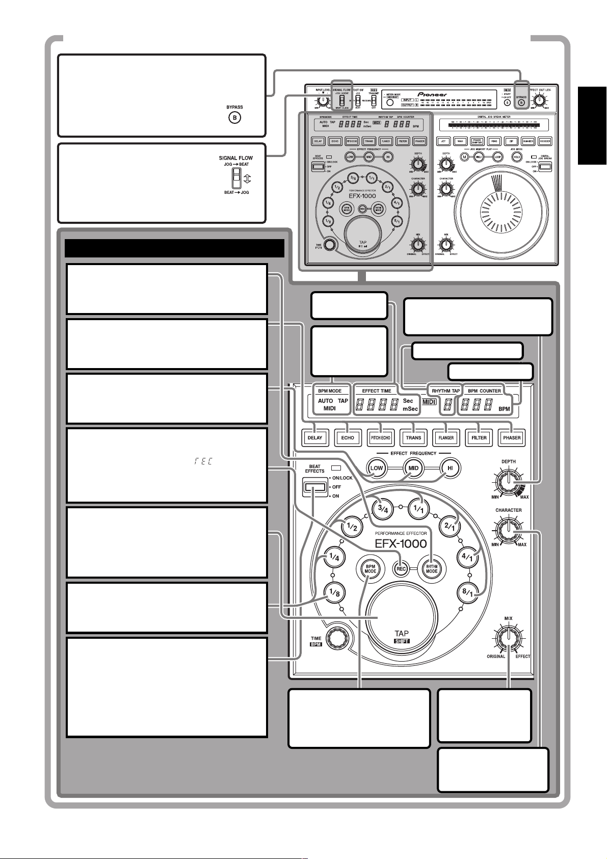
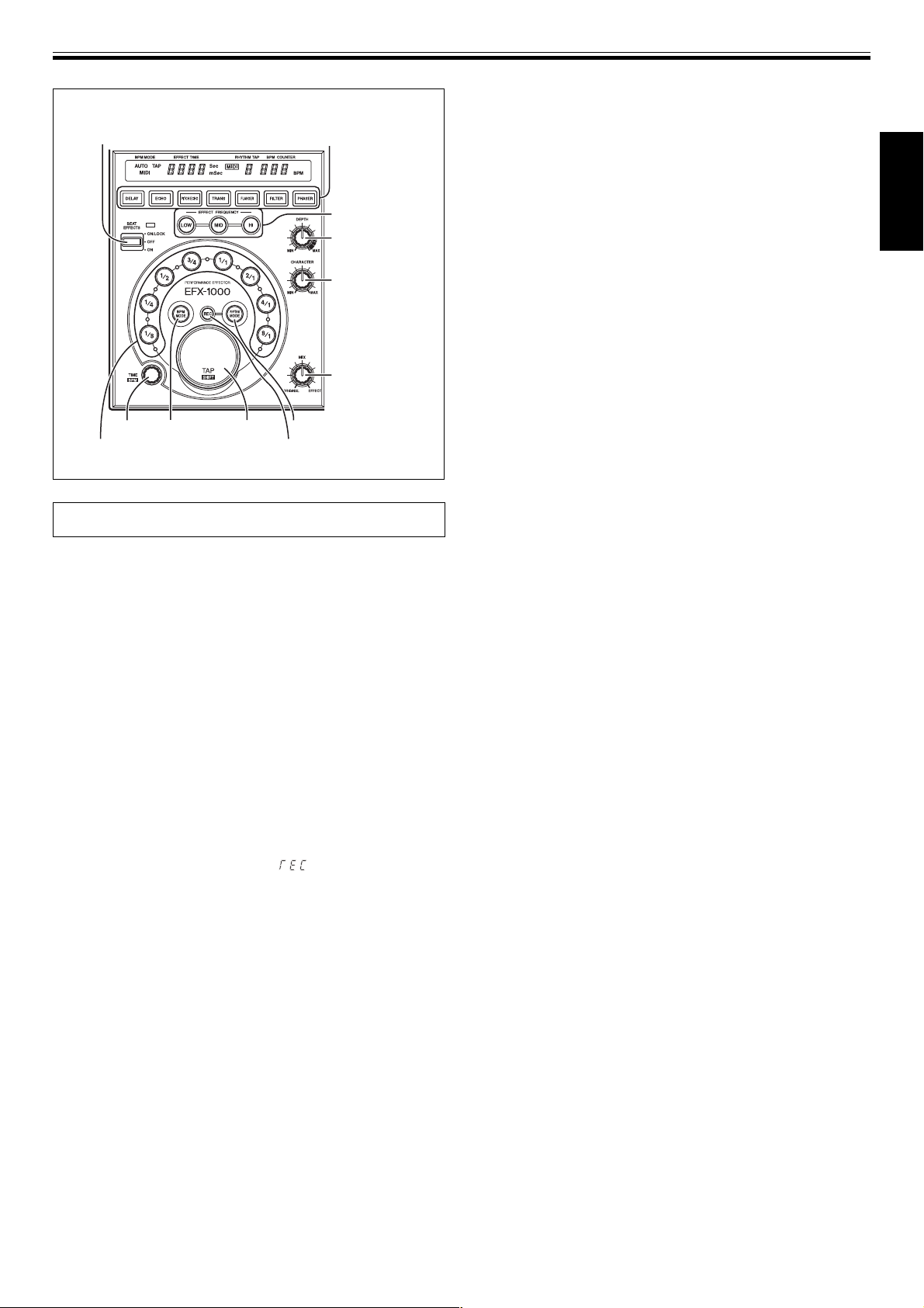
QUICK OPERATION GUIDE (1/3)
Adjusting the input level
Input signals to the input
connectors, and adjust the
INPUT LEVEL dial.
Adjusting effect output level
Rotate the EFFECT OUT LEV. dial to
adjust the effect output level.
Changing the level meter display mode
Each time the METER MODE button is pressed, the
level meter display alternates as follows:
÷ INPUT, OUTPUT light: Input and output monaural
display.
÷ INPUT, L, R light: Input stereo display.
USING BEAT EFFECTS [BPM MODE]
1. Select the BPM measurement mode.
Press the BPM MODE button so that the
button lights together with the desired mode
indicator (AUTO/MIDI/TAP).
2. Select effect type.
Press the DELAY, ECHO, PITCH ECHO,
TRANS, FLANGER, FILTER or PHASER button
and the pressed button starts to flash.
3. Select the sound range for the effect.
Press the button of the frequency (LOW, MID,
HI) you wish to affect by the beat effect and
the corresponding indicator lights.
OUTPUT, L, R
÷
EFFECT TIME
display
BPM
measurement
mode
indicators
light: Output stereo display.
DEPTH dial
Sets the parameter 1 of each
effect.
RHYTHM TAP display
BPM COUNTER
4. Select the beat with which the effect is
to be synchronized.
Press a beat select button (1/8, 1/4, 1/2, 3/4,
1/1, 2/1, 4/1 or 8/1) to light the desired button.
5. Apply an effect.
Press the lever towards you (ON position) to
start operation; release it and it returns to
the center position (OFF position). In the
center position (OFF position), the original
sound is not affected. Press the lever away
from you to lock it in position so that the
beat effect is applied also when the lever is
released.
TIME/BPM dial
Set the desired effect time as in step 4.
Turn the TIME/BPM dial while holding down
the TAP/SHIFT button to make the desired
BPM setting. When also the BPM MODE
button is held down, BPM can be set in 0.1
increments.
TAP/SHIFT button
BPM can be manually adjusted by adjusting
the beat (quarter notes) and hitting this key
two times or more.
MIX dial
Adjusts the balance between
the original sound and effects.
CHARACTER dial
Sets the parameter 2 of each
effect.
4
<DRB1369>
QUICK OPERATION GUIDE (2/3)
BYPASS button
When the button is pressed (button
indicator flashes), the signal entering
the input connectors is output
directly (without modification) to the
output connectors.
SIGNAL FLOW switch
Selects the order in which signals
are passed through the electronic
sections (from beat effect to digital
jog break, or vice versa).
USING BEAT EFFECTS [RHYTHM MODE]
1. Select the rhythm input mode.
Press the RHYTHM MODE button so that the
button indicator lights.
2. Select effect type.
Press the DELAY, ECHO, PITCH ECHO, TRANS,
FLANGER, FILTER or PHASER button and the
pressed button starts to flash.
3. Select the sound range for the effect.
Press the button of the frequency (LOW, MID,
HI) you wish to affect by the rhythm effect and
the corresponding indicator lights.
EFFECT
TIME display
BPM
measurement
mode
indicators
DEPTH dial
Sets the parameter 1 of each
effect.
RHYTHM TAP display
BPM COUNTER
English
4. Set to REC mode.
¶ When the REC button is pressed, the
BPM display indicates “
¶ If no rhythm has been input, the unit
will automatically enter the REC mode
in step 1.
”.
5. Input the rhythm.
Tap your finger on the TAP button to input the
desired rhythm. As you input the rhythm, the
rhythm will be calculated and displayed on the
RHYTHM TAP display (up to 8 taps with tap
interval of 2 seconds or less).
6. Select the overall rhythm time.
The pressed beat select button will light, and
the overall rhythm time will be set at the
multiple corresponding to the pressed button.
7. Apply an effect.
Press the lever towards you (ON position) to
start operation; release it and it returns to the
center position (OFF position). In the center
position (OFF position), the original sound is
not affected. Press the lever away from you to
lock it in position so that the rhythm effect is
applied also when the lever is released.
BPM MODE button
When the BPM MODE button is
pressed while in the rhythm
mode, the mode changes to
the beat effect BPM mode.
MIX dial
Adjusts the balance
between the original
sound and effects.
CHARACTER dial
Sets the parameter 2 of
each effect.
<DRB1369>
5
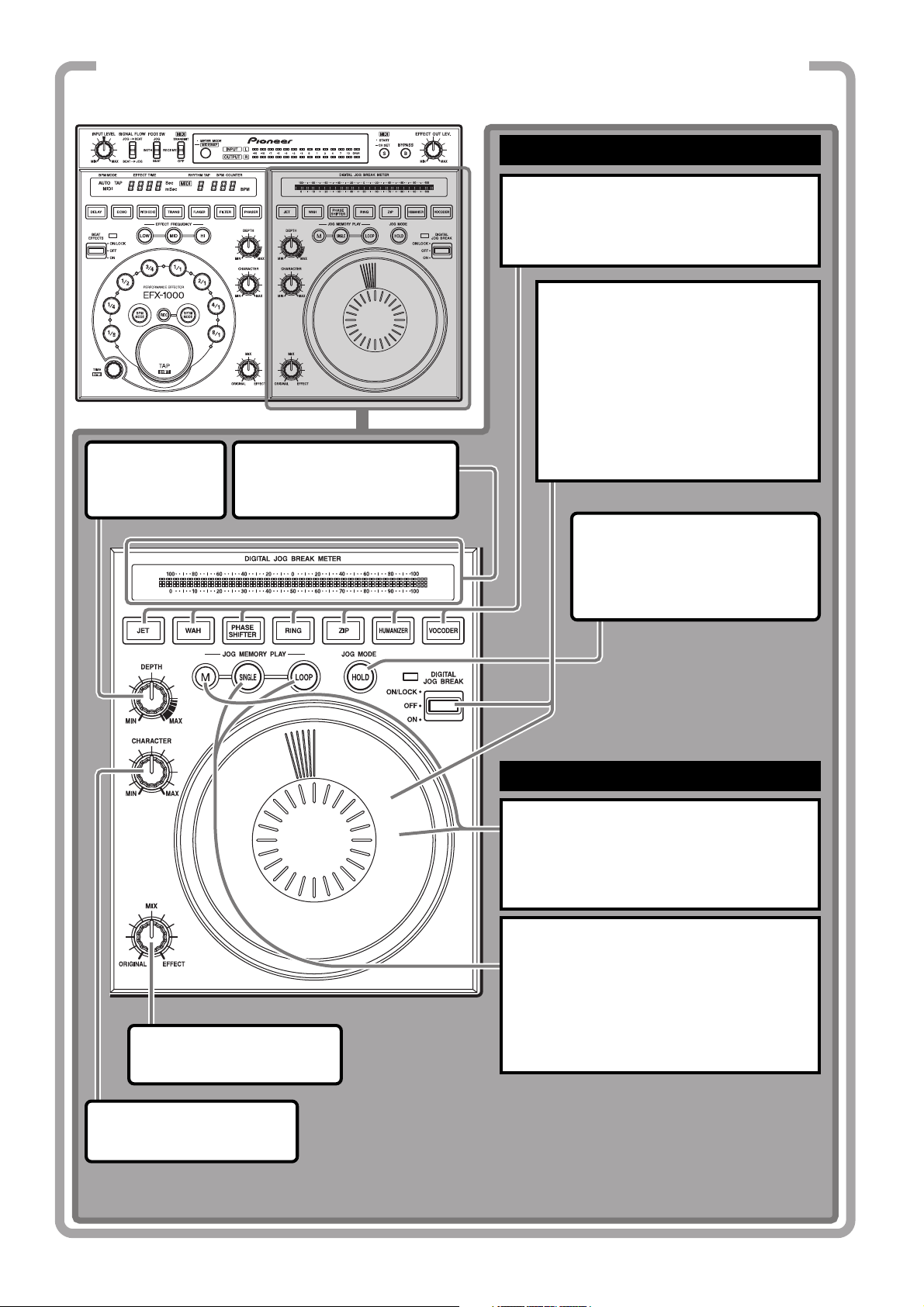
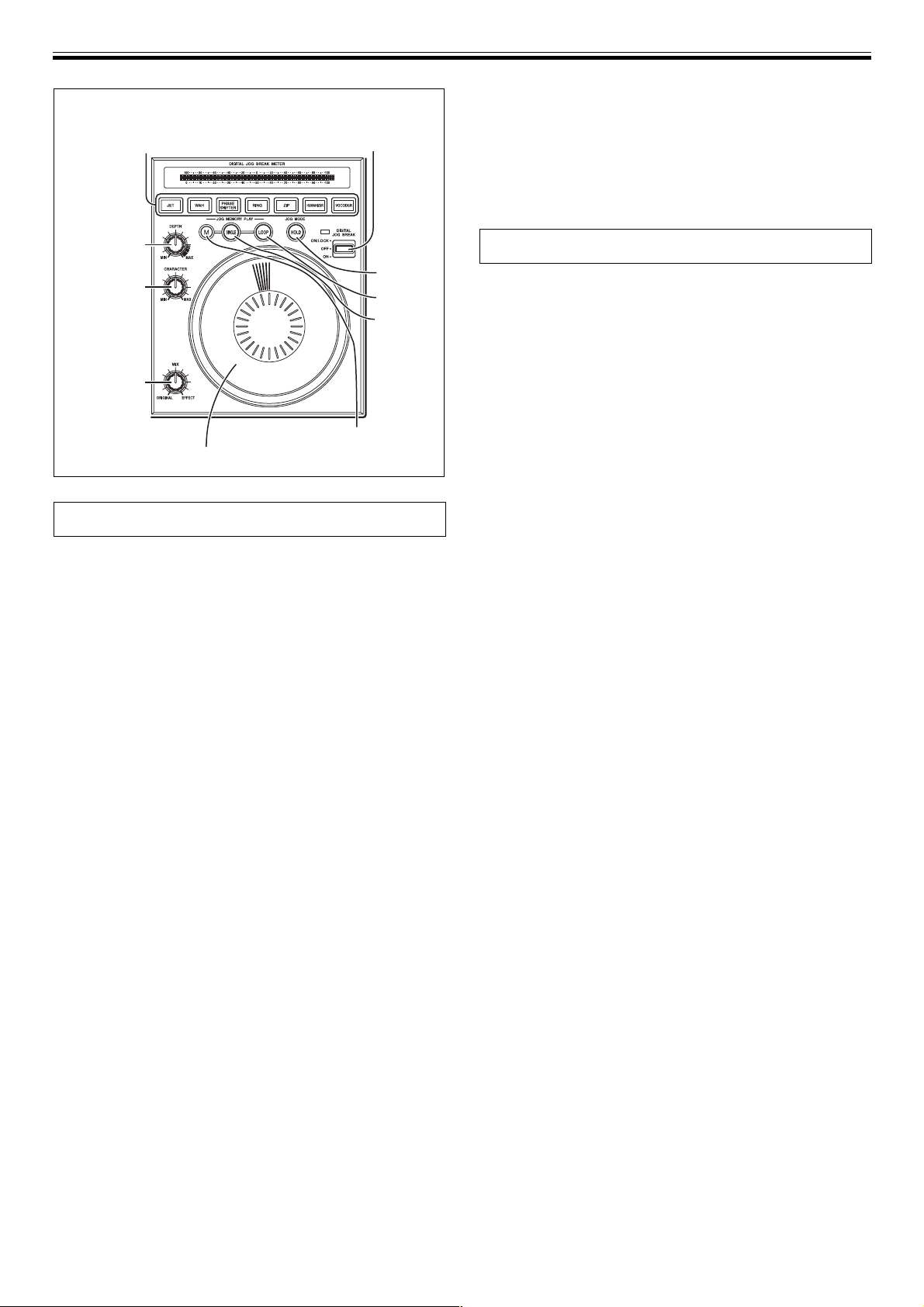
QUICK OPERATION GUIDE (3/3)
USING THE DIGITAL JOG BREAK
1. Select the desired effect.
Press the desired effect button, JET, WAH,
PHASE SHIFTER, RING, ZIP, HUMANIZER or
VOCODER to flash the corresponding button.
2. Apply the desired effect.
Turn the Jog dial either while pressing the
lever towards you or pressing it away
from you (ON position). As the Jog dial is
turned, parameters change gradually and
the selected effect is applied. When the
dial rotation is stopped, the parameter
returns to normal.
When the lever is pressed towards you,
releasing it causes it to automatically
DEPTH dial
Sets the parameter
1 of each effect.
DIGITAL JOG BREAK METER
Indicates the amount of control
exercised by the Jog dial.
return to the center (OFF position).
MIX dial
Adjusts the balance between
the original sound and effects.
HOLD button
When this button is pressed so that
the button indicator lights, effects
produced with the Jog dial will
continue even when your hand is
removed from the dial.
USING JOG MEMORY PLAY
1. Hold the Jog memory button (M)
depressed while rotating the Jog dial.
Effect changes produced with the Jog dial will be
stored in memory (maximum 8 seconds). When
storage is completed, the SINGLE and LOOP
buttons light.
2. Press the SINGLE button or LOOP
button
÷ When the SINGLE button is pressed, the
stored Jog-dial effect change will be replayed
one time only.
÷ When the LOOP button is pressed, the stored
Jog-dial effect change will be replayed
repeatedly. Press the button once more to stop
the effect.
CHARACTER dial
Sets the parameter 2 of each
effect.
6
<DRB1369>
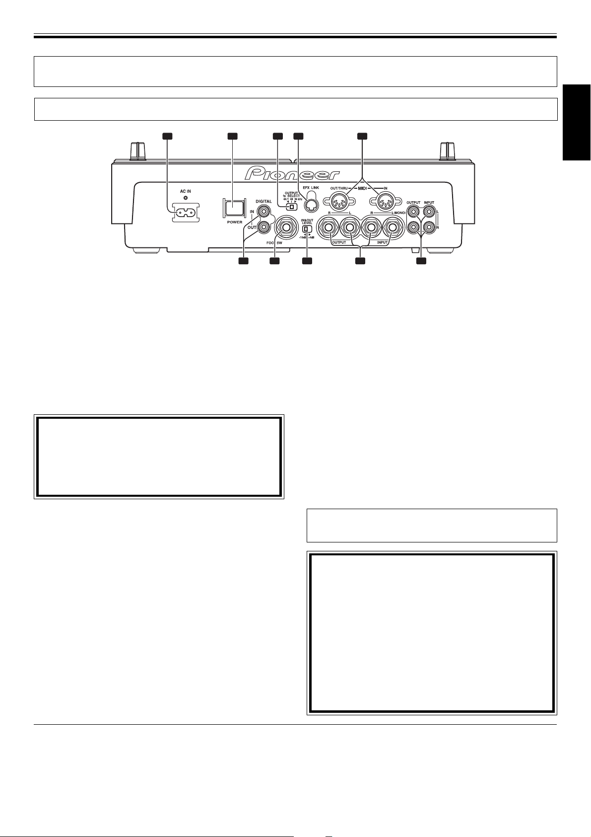
CONNECTIONS
Connection Panel
BEFORE USE (CONNECTIONS)
2 3 4 51
6 7 8 9 10
1 Power input socket (AC IN)
Use the provided power cord to connect this socket to an
AC outlet.
2 POWER switch
3 Digital OUTPUT fs SELSECT switch
Use to change the digital output frequency sampling rate
(fs) (44.1kHz/48kHz/96kHz).
4 Link input/output connector (EFX LINK)
When the accessory digital link cable is used to connect
this connector to the DJ-mixer DJM-1000 (with digital link
support), digital link functions can be used, permitting a
variety of new functions.
CAUTION:
The EFX LINK connector is designed to be connected
via the provided digital link cable ONLY to a component
equipped with the designated digital link function.
The unit may be damaged if this connector is
mistakenly connected to any other component.
5. MIDI input/output connectors (MIDI OUT/THRU,
MIDI IN)
Use to connect the effector to a MIDI component (see page 21).
6 Digital input/output connectors (DIGITAL IN,
DIGITAL OUT)
Use to connect the effector to a component provided with
coaxial digital input/output connectors.
7 Foot switch jack (FOOT SW)
Can be connected to a ON/OFF type foot switch with 6.3mm
phone plug to allow ON/OFF control of effects.
Foot switches are available in several types, including
press-ON, press-OFF, and latching-type ON/OFF.
8 Input/output gain select switch (IN&OUT LEVEL)
Use to select the input/output gain (–10dB / +4dB).
9 Audio INPUT/OUTPUT jacks
Uses 6.3mm phones plug. For monaural inputs, connect L
input channel only for output on both L and R channels.
Audio inputs are throughput (output) even when the unit’s
power is turned OFF.
10 Audio INPUT/OUTPUT jacks
INPUT/OUTPUT connectors using RCA pin jacks.
Audio inputs are throughput (output) even when the unit’s
power is turned OFF.
7
Before making or changing the connections,
switch off the power switch and disconnect the
power cord from the AC outlet. This precaution
should also be taken when changing the IN & OUT
LEVEL switch and DIGITAL fs SELECT switch.
÷ When connections are made to the phone jack inputs
and a monaural signal cable is connected to the L
(MONO) terminal, inputs can be made to both the L and
R channels.
÷ After all other connections are made, connect the power
cord to a household wall outlet or to the auxiliary AC
power takeoff on your amplifier.
See page 21 for instructions on how to
use the MIDI terminals.
CAUTION:
Do not make any connections that may create signal
loops as this will cause circuit oscillations which
could damage the speakers.
[Example of connections that must not be
performed]
¶ Do not connect the output of the DJ Mixer to the
input terminal of the Effector and the output of the
Effector to the input terminal of the same mixer.
¶ Do not connect the SEND output of the DJ Mixer to
the input terminal of the Effector and the output of
the Effector to the input terminal of the DJ Mixer
(except for the RETURN terminal).
English
Installation Location
÷ Avoid mounting on top of amplifiers, near spotlights, or
other heat-emitting components and appliances;
extended exposure to heat can cause damage to the
effector itself.
÷ Install this unit as far as possible away from tuners and TV
sets. A unit installed in close proximity to such equipment
may cause noise or degradation of the picture.
Cleaning the unit
To clean the unit wipe with a polishing or a soft, dry cloth.
For stubborn dirt, moisten a soft cloth with a weak solution
of neutral detergent (diluted in five to six parts water),
wring the cloth well, and wipe away the dirt. Use a dry cloth
to wipe the surface dry. Do not use volatile liquids such as
benzene or thinner which will damage to the unit.
<DRB1369>
7
BEFORE USE (CONNECTIONS)
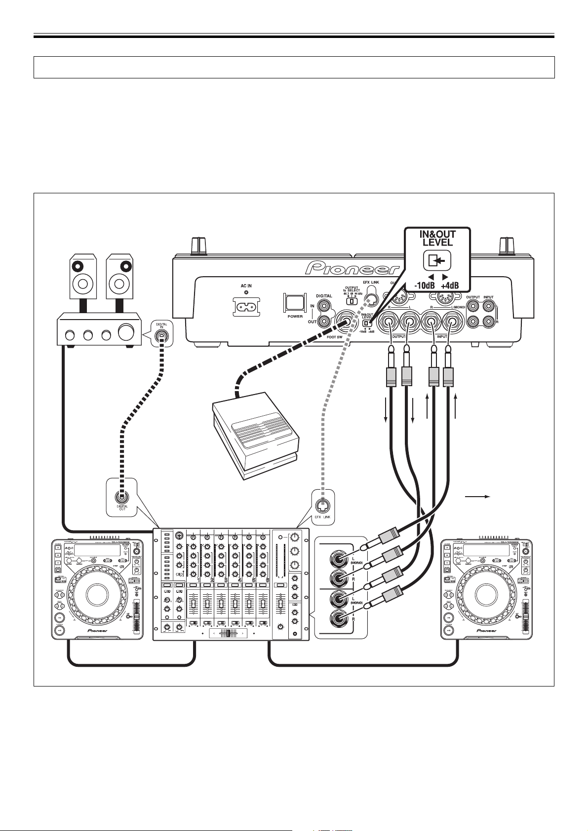
Basic Connections
Before making or changing the connections, switch off the power switch and disconnect the power cord from the AC outlet.
1. Connecting the SEND/RETURN Terminals on the
DJ Mixer (on DJ mixer provided with SEND and
RETURN terminals)
÷ Make connections using cables with 1/4-inch/6.3 mm in
diameter phone plugs.
÷ Set the DJ mixer so that the SEND and RETURN
terminals can be used.
Effector EFX-1000
Stereo Amplifier
÷ If the DJ mixer supports digital link, it can be connected
to the EFX LINK connector using the provided digital link
cable to eliminate the need for connection by an analog
6.3mm phone plug cable (audio signals transmitted over
the digital link cable are in digital format).
÷ Set the IN & OUT LEVEL switch on the Effector
to the [–10 dB] position.
FOOT SW
OUTPUT
INPUT
EFX LINK
Accessory
digital
Foot switch
link cable
(pedal switch)
: Signal flow
MASTER OUT
DJ CD Player DJ CD Player
CH-1
DJ Mixer
SEND
SEND 1
–26 +6
RETURN
RETURN 1
CH-2
2. Connecting a DJ Mixer and an Audio Amplifier
(on DJ mixer not provided with SEND and
RETURN terminals)
÷ Connect using cables with phone plugs (1/4-inch/6.3 mm
in diameter) or RCA pin plugs.
8
<DRB1369>
÷ When making connections, do not connect both RCA pin
plug cables and phones plug cables for the same
connection function (use either one or the other, not
both). Also, if you wish to use analog connections, do
not also make connections to the digital connectors
(digital signals are given priority when connected).
¶ For digital connections, use RCA pin-plug coaxial cables.
Set the OUTPUT fs SELECT switch in accordance with
the connected component.
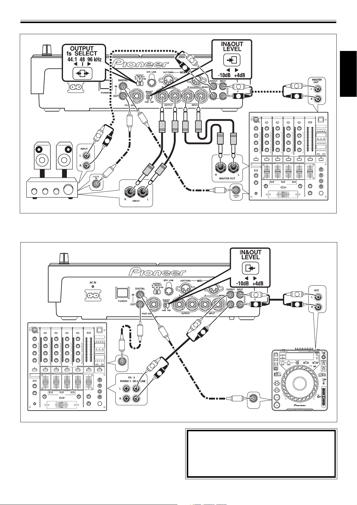
BEFORE USE (CONNECTIONS)
Effector EFX-1000
Stereo Amplifier
OUTPUT
L
R
÷ Set the IN & OUT LEVEL switch
on the Effector to the [+4 dB]
position.
MASTER OUT
L
R
L
R
English
INPUT
INPUT
L
R
MASTER OUT
DIGITAL OUT
DJ Mixer
3. Connecting a DJ CD Player and a DJ Mixer (this
connection applies effects only to the sound of
the DJ CD player on channel 2)
Effector EFX-1000
DIGITAL OUT
DIGITAL
DIGITAL
IN
IN
L
R
DIGITAL
IN
¶ Connect the units using a cable with RCA pin plugs.
¶ For digital connections, use RCA pin-plug coaxial cables.
÷ Set the IN & OUT
LEVEL switch on the
Effector to the [–10 dB]
position.
AUDIO OUT
L
R
INPUT
L
OUTPUT
R
DIGITAL OUT
L
R
DJ Mixer
4. Connecting the power cord
÷ After all other connections are completed, insert the
power cord’s plug into a wall power outlet or the
auxiliary power outlet of an amplifier.
DIGITAL
OUT
DJ CD Player
CAUTION:
Signal inputs are handled in a specific order of
priority:
EFX LINK > digital inputs > analog inputs
When EFX LINK signals are input, digital signals are
not output.
<DRB1369>
9
EFFECTS (Beat Effects)
EFFECTS
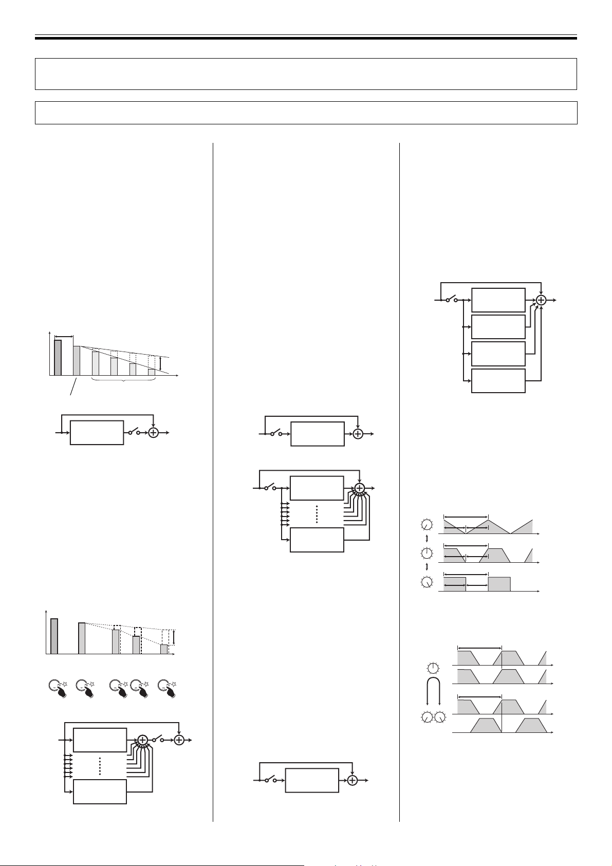
Beat Effects
1. DELAY effect
Adds delay sound to the original sound.
[BPM mode]
A delay sound is added to the original
sound at the value set with the TIME dial.
÷ The DEPTH dial can be used to adjust
the feedback level. Feedback means to
input the delay sound back into the
delay input. This control allows the
amount of the feedback to be adjusted
(near the [MAX] setting, the sound level
rises).
÷ The CHARACTER dial can be used to
adjust the amount of filter applied to the
feedback sound.
÷ The MIX dial can be used to adjust the
levels of the original and delay sounds.
TIME
Sound level
Original
sound
Delay sound
Delay block
Feedback
[RHYTHM mode]
A delay sound set with the TAP button
(TAP delay sound) is added to the original
sound (Max 8-TAP).
÷ The DEPTH dial can be used to adjust
the TAP delay level (near the [MAX]
setting the sound volume will rise).
÷ The CHARACTER dial can be used to
adjust the amount of filter applied to the
TAP delay sound.
÷ The MIX dial can be used to adjust the
levels of the original and TAP delay
sounds.
Sound level
Original
Delay
sound
sound
TAP 0 TAP 1 TAP 2 TAP 3 TAP 4
TAP 1 delay
block
TAP 8 delay
block
Delay
sound
Delay
sound
DEPTH
Delay
sound
Time
DEPTH
Time
2. ECHO effect
Adds delay sound to the original sound.
[BPM mode]
A delay sound is added to the original
sound at the value set with the TIME dial.
[RHYTHM mode]
Adds TAP delay sound to the original
sound (Max 8-TAP).
Difference from the DELAY effect:
÷ Even if the BEAT EFFECTS lever switch
is moved from [ON] to [OFF], the
feedback sound or TAP delay sound will
continue.
÷ In the BPM mode, if the DEPTH dial is
set to [MAX] and the BEAT EFFECTS
lever switch is moved from [ON] to
[OFF], a hold-delay effect will be
produced without attenuating the
feedback sound (near the [MAX] setting,
the sound level rises).
In the RHYTHM mode, when the switch
is turned [OFF] the effect will end with
the final TAP delay sound for the
original sound.
BPM mode
Echo block
RHYTHM mode
TAP 1 echo
block
TAP 8 echo
block
3. PITCH ECHO effect
Changes the pitch of the delay sound, and
applies the effect to the original sound.
In the same way as for the ECHO effect, the
effect sound is maintained even if the BEAT
EFFECTS lever switch is set from [ON] to
[OFF].
[BPM mode]
Changes the pitch of the delay sound set
with the TIME dial, and applies the effect to
the original sound.
÷ The DEPTH dial can be used to adjust
the feedback level.
÷ The CHARACTER dial can be used to
adjust the pitch of the delay sound.
÷ The MIX dial can be used to adjust the
levels of the original and pitch echo
sounds.
Pitch echo
block
[RHYTHM mode]
Changes the pitch of the TAP delay sound,
and applies the effect to the original sound
(Max 4-TAP).
÷ The DEPTH dial can be used to adjust
the TAP delay level (near the [MAX]
setting the sound volume will rise
somewhat).
÷ The CHARACTER dial can be used to
adjust the pitch of the TAP delay sound.
÷ The MIX dial can be used to adjust the
levels of the original and pitch echo
sounds.
TAP 1 pitch
echo block.
TAP 2 pitch
echo block.
TAP 3 pitch
echo block.
TAP 4 pitch
echo block.
4. TRANS effect
Cuts the original sound intermittently.
[BPM mode]
Cuts the sound at the interval set by the
TIME dial (cuts latter half of the interval).
÷ The DEPTH dial can be used to adjust
the amount of shift when the sound is
cut.
DEPTH
MIN
DEPTH
DEPTH
÷ The CHARACTER dial can be used to
adjust the phase difference between L
and R channels.
CHARACTER
CHARACTER
÷ The MIX dial can be used to adjust the
levels of the original and trans sounds.
TIME
TIME
TIME
MAX
TIME
L-ch
R-ch
TIME
L-ch
MAXMIN
R-ch
Time
Time
Time
Time
Time
Time
Time
10
<DRB1369>
EFFECTS (Beat Effects)
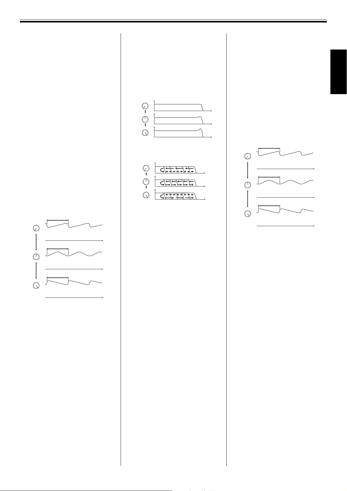
[RHYTHM mode]
Cuts the original sound in synch with the
TAP rhythm (Max 8-TAP).
÷ The DEPTH dial can be used to adjust the
amount of shift when the sound is cut.
÷ The CHARACTER dial can be used to
adjust of phase difference between L
and R channels.
÷ The MIX dial can be used to adjust the
levels of the original and trans sounds.
5. FLANGER effect
By applying a time-shifted sound to the
original, the effect of an ascending or
descending jet plane (flange effect) is
produced.
[BPM mode]
Changes the frequency range to which the
flange effect is applied at the interval set by
the TIME dial.
÷ The DEPTH dial can be used to adjust
the strength of the flange effect by
changing the amount of resonance.
(When approaching the [MAX] setting,
the level of the sound increases.)
÷ The CHARACTER dial can be used to
adjust the cyclic changes in the flange
effect.
÷ The MIX dial can be used to adjust the
levels of the original and flanger sounds.
CHARACTER
MIN
CHARACTER
CHARACTER
[RHYTHM mode]
Changes the frequency subjected to flange
effect, in synch with the TAP rhythm.
÷ The DEPTH dial can be used to adjust
the strength of the flange effect by
changing the amount of resonance.
(When approaching the [MAX] setting,
the level of the sound increases.)
÷ The CHARACTER dial can be used to
adjust the cyclic changes in the flange
effect.
÷ The MIX dial can be used to adjust the
levels of the original and flanger sounds.
TIME
Flange effect change
TIME
Flange effect change
TIME
MAX
Flange effect change
Time
Time
Time
6. FILTER effect
A low-pass filter is applied to the original
sound to produce more muted sound.
[BPM mode]
The cutoff frequency of the low-pass filter
changes with the cycle set by the TIME dial.
÷ The DEPTH dial is used to change the
unique coloring of the sound by
adjusting the amount of resonance.
(When approaching the [MAX] setting,
the level of the sound increases.)
DEPTH
MIN
DEPTH
DEPTH
MAX
÷ The CHARACTER dial can be used to
vary the cutoff frequency of the cyclic
low-pass filter.
CHARACTER
MIN
CHARACTER
CHARACTER
MAX
÷ The MIX dial can be used to adjust the
levels of the original and filter sounds.
[RHYTHM mode]
Changes cutoff frequency of the low-pass
filter, in synch with the TAP rhythm (Max 8TAP).
÷ The DEPTH dial is used to change the
unique coloring of the sound by
adjusting the amount of resonance.
(When approaching the [MAX] setting,
the level of the sound increases.)
÷ The CHARACTER dial can be used to
vary the cutoff frequency of the cyclic
low-pass filter.
÷ The MIX dial can be used to adjust the
levels of the original and filter sounds.
7. PHASER effect
Causes a phase effect by applying a phaseshifted sound to the original sound.
[BPM mode]
Changes the frequency range to which the
phase effect is applied at the interval set by
the TIME dial.
÷ The DEPTH dial can be used to adjust
the strength of the phase effect by
changing the amount of resonance.
(When approaching the [MAX] setting,
the level of the sound increases.)
÷ The CHARACTER dial can be used to
adjust the cyclic changes in the phase
effect.
÷ The MIX dial can be used to adjust the
levels of the original and phaser
sounds.
CHARACTER
MIN
CHARACTER
CHARACTER
[RHYTHM mode]
Changes the frequency subjected to phase
effect, in sync with the TAP rhythm.
÷ The DEPTH dial can be used to adjust
the strength of the phase effect by
changing the amount of resonance.
(When approaching the [MAX] setting,
the level of the sound increases.)
÷ The CHARACTER dial can be used to
adjust the cyclic changes in the phase
effect.
÷ The MIX dial can be used to adjust the
levels of the original and phaser
sounds.
TIME
Phase effect change
TIME
Phase effect change
TIME
MAX
Phase effect change
Time
Time
Time
English
11
<DRB1369>
EFFECTS (Digital Jog Break)
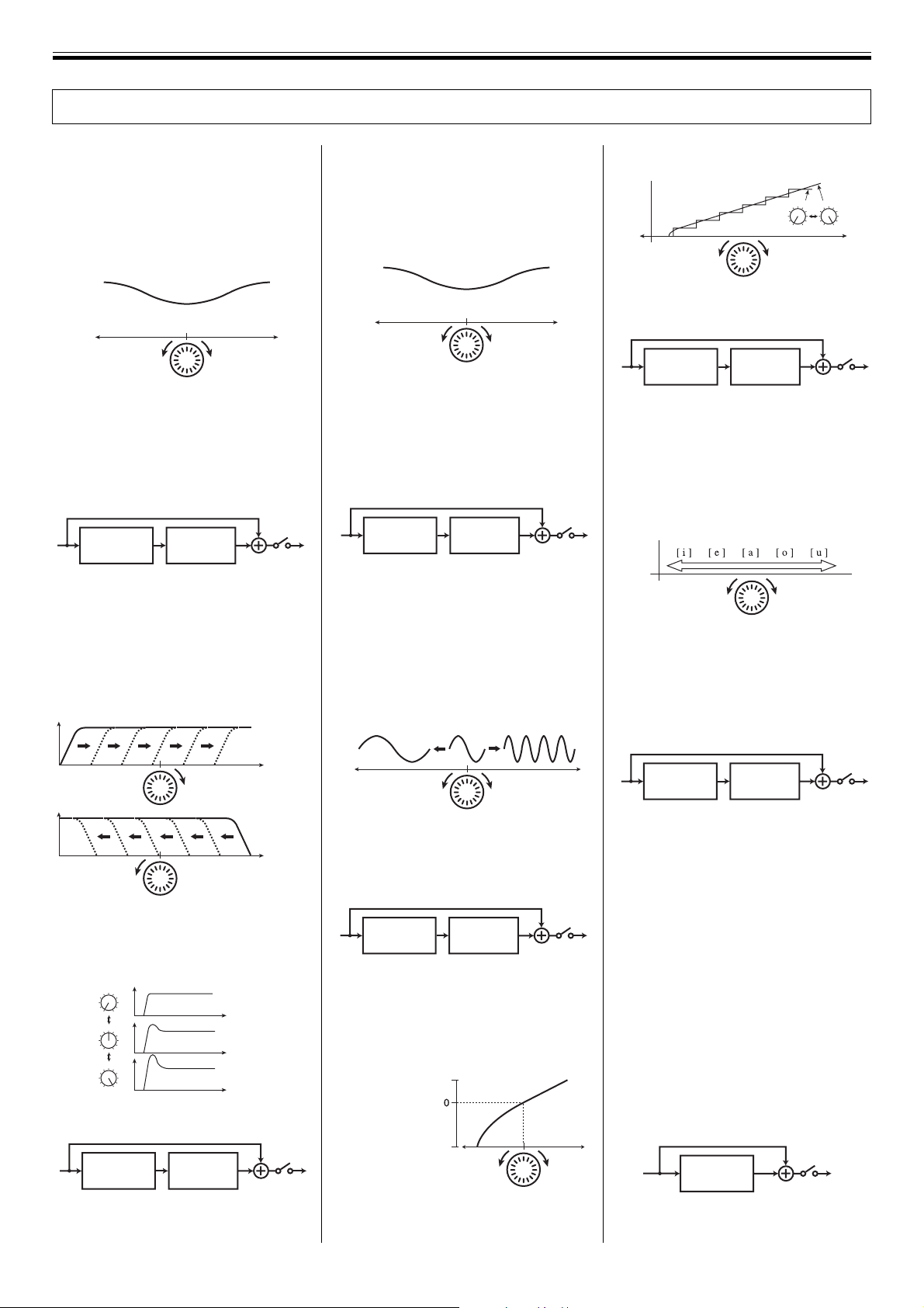
Digital Jog Break
1. JET effect
A time-shifted sound is applied to the
original, thus producing the effect of a jet
airplane ascending or descending (flange
effect).
÷ The Jog dial is used to change the
frequency range that is affected by the
flange effect.
Flange effect change
REV
Jog dial
FWD
÷ The amount of resonance is changed
using the DEPTH dial to emphasize the
flange effect. (When approaching the
[MAX] setting, the level of the sound
increases.)
÷ The CHARACTER dial can be used to
adjust the reverb effect.
Jet block
Reverb
block
÷ The MIX dial can be used to adjust the
levels of the jet + reverb sound and
original sound.
2. WAH effect
The filter’s cutoff frequency is shifted,
causing great change in the sound tone.
÷ The Jog dial is used to vary the filter’s
cutoff frequency.
3. PHASE SHIFTER effect
A phase-shifted sound is added to the
original, thus producing a phase shifter
effect.
÷ The Jog dial is used to change the
frequency range that is affected by the
phase effect.
Phase effect change
REV
Jog dial
FWD
÷ The amount of resonance is changed
using the DEPTH dial to emphasize the
phase effect. (When approaching the
[MAX] setting, the level of the sound
increases.)
÷ The CHARACTER dial can be used to
adjust the reverb effect.
Phase shifter
block
Reverb
block
÷ The MIX dial can be used to adjust the
levels of the phase shifter + reverb
sound and the original sound.
4. RING modulator effect
By modulating the original sound in the
shape of a sine wave, the resulting sound
coloration resembles a ringing bell.
÷ The Jog dial is used to vary the sine
wave frequency.
÷ The DEPTH dial can be used to adjust
the Jog dial’s variable range (step).
DEPTH
DEPTH
MIN
MAX
REV FWD
Jog dial
÷ The CHARACTER dial can be used to
adjust the reverb effect
Zip block
Reverb
block
÷ The MIX dial can be used to adjust the
levels of the zip+reverb and original
sounds.
6. HUMANIZER effect
The original sound is modified to resemble
the vowel sounds of the human voice.
÷ The Jog dial is used to vary the vowel
sound coloration.
REV FWD
Jog dial
÷ The DEPTH dial is used to change the
unique coloring of vowel sounds by
adjusting the amount of resonance.
(When approaching the [MAX] setting,
the level of the sound increases.)
÷ The CHARACTER dial can be used to
adjust the reverb effect.
Frequency
Jog dial
Frequency
Jog dial
÷ The DEPTH dial is used to change the
unique coloring of the sound by
adjusting the amount of resonance.
(When approaching the [MAX] setting,
the level of the sound increases.)
DEPTH
MIN
DEPTH
DEPTH
MAX
Frequency
Frequency
Frequency
÷ The CHARACTER dial can be used to
adjust the reverb effect.
Wah block
Reverb
block
÷ The MIX dial can be used to adjust the
levels of the wah + reverb sound and the
original sound.
REV
Jog dial
FWD
÷ The DEPTH dial can be used to adjust
the amplitude of the sine wave.
÷ The CHARACTER dial can be used to
adjust the reverb effect.
Ring block
Reverb
block
÷ The MIX dial can be used to adjust the
levels of the ring + reverb and original
sounds.
5. ZIP effect
The Jog dial is used to change the pitch.
Up (about 1 octave)
’
Pitch
Down
(about 15 octaves)
Original
‘
sound
REV
FWD
Jog dial
Humanizer
block
Reverb
block
÷ The MIX dial can be used to adjust the
levels of the humanizer + reverb and the
original sounds.
7. VOCODER effect
The input sound is replaced by an internally generated signal sound, producing a
mechanical sound effect.
÷ The Jog dial is used to change the
frequency of the internally generated
signal sound.
÷
The DEPTH dial can be used to vary the
internally generated sound from the basic
sound to a chord. (The sound more nearly
approximates the chord as the adjustment
approaches the [MAX] setting.)
÷ The CHARACTER dial can be used to
change chords codes. Selectable codes
include Minor (MIN), Minor7, 7, Major
(center position), Major7, Sus4, and Add9
(MAX).
Vocoder
block
÷ The MIX dial can be used to adjust the
levels of the vocoder and original sounds.
12
<DRB1369>
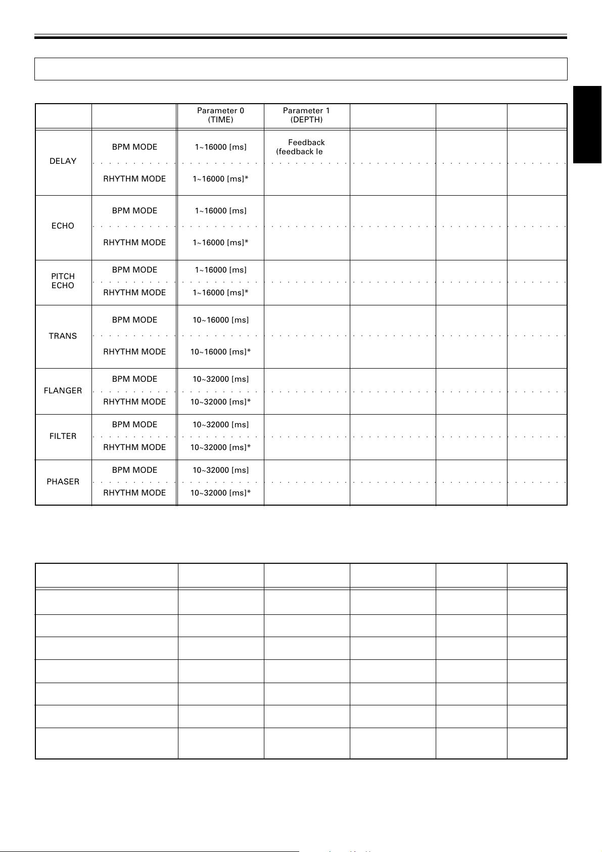
Effect Parameters
Beat effect
EFFECTS (Effect Parameters)
DELAY
ECHO
PITCH
ECHO
TRANS
FLANGER
FILTER
PHASER
Parameter 0
(TIME)
BPM MODE
○○○○○○○○○○○○○○○○○○○○○○○○○○○○○○○○○○○○○○○○○○○○○○○○○○○○○○○○○○○
RHYTHM MODE
BPM MODE
○○○○○○○○○○○○○○○○○○○○○○○○○○○○○○○○○○○○○○○○○○○○○○○○○○○○○○○○○○○
RHYTHM MODE
BPM MODE
○○○○○○○○○○○○○○○○○○○○○○○○○○○○○○○○○○○○○○○○○○○○○○○○○○○○○○○○○○○
RHYTHM MODE
BPM MODE
○○○○○○○○○○○○○○○○○○○○○○○○○○○○○○○○○○○○○○○○○○○○○○○○○○○○○○○○○○○
RHYTHM MODE
BPM MODE
○○○○○○○○○○○○○○○○○○○○○○○○○○○○○○○○○○○○○○○○○○○○○○○○○○○○○○○○○○○
RHYTHM MODE
BPM MODE
○○○○○○○○○○○○○○○○○○○○○○○○○○○○○○○○○○○○○○○○○○○○○○○○○○○○○○○○○○○
RHYTHM MODE
BPM MODE
○○○○○○○○○○○○○○○○○○○○○○○○○○○○○○○○○○○○○○○○○○○○○○○○○○○○○○○○○○○
RHYTHM MODE
1~16000 [ms]
1~16000 [ms]*
1~16000 [ms]
1~16000 [ms]*
1~16000 [ms]
1~16000 [ms]*
10~16000 [ms]
10~16000 [ms]*
10~32000 [ms]
10~32000 [ms]*
10~32000 [ms]
10~32000 [ms]*
10~32000 [ms]
10~32000 [ms]*
Parameter 1
(DEPTH)
Feedback
(feedback level)
TAP gain
(TAP delay level)
Feedback
(feedback level)
TAP gain
(TAP delay level)
Feedback
(feedback level)
TAP gain
(TAP delay level)
Shape
(cut shift)
Shape
(cut shift)
Resonance
Resonance
Resonance
Resonance
Resonance
Resonance
Parameter 2
(CHARACTER)
Feedback filter
(Amount of
feedback filter)
TAP filter
(Amount of TAP
delay filter)
Feedback filter
(Amount of
feedback filter)
TAP filter
(Amount of TAP
delay filter)
Pitch
(delay sound pitch)
TAP Pitch
(TAP delay sound pitch)
Phase
(L/R-ch phase
difference)
Phase
(L/R-ch phase
difference)
LFO pattern
(change cyclic effect)
LFO pattern
(change cyclic effect)
LFO pattern
(change cyclic effect)
LFO pattern
(change cyclic effect)
LFO pattern
(change cyclic effect)
LFO pattern
(change cyclic effect)
Parameter 3
(MIX)
MIX
MIX
MIX
MIX
MIX
MIX
MIX
MIX
MIX
MIX
MIX
MIX
MIX
MIX
Comments
—
Max 8-TAP
—
Max 8-TAP
—
Max 4-TAP
—
Max 8-TAP
—
Max 8-TAP
—
Max 8-TAP
—
Max 8-TAP
* The effect time display in the rhythm mode shows the total time from the beginning to end of TAP
input. For this reason, the noted MIN time may be somewhat different from the effect time display.
English
Digital Jog Break
JET
WAH
PHASE SHIFTER
RING
ZIP
HUMANIZER
VOCODER
Parameter 0
(JOG)
Delay time
(amount of delay)
Frequency
(filter frequency)
Frequency
(filter coefficient)
Frequency
(sine wave frequency)
Pitch
(Scale)
Vowel
(vowel sound)
Oscillator frequency
(internally generated
sound frequency)
Parameter 1
(DEPTH)
Resonance
Resonance
Resonance
Amplitude
(sine-wave amplitude
)
Step
(ScaleÔLinear)
Resonance
Chord MIX
(chord MIX ratio)
Parameter 2
(CHARACTER)
Reverb
(reverberation effect)
Reverb
(reverberation effect)
Reverb
(reverberation effect)
Reverb
(reverberation effect)
Reverb
(reverberation effect)
Reverb
(reverberation effect)
Chord
Parameter 3
(MIX)
MIX
MIX
MIX
MIX
MIX
MIX
MIX
Comments
—
—
—
—
—
—
—
13
<DRB1369>
BEFORE USE (CONTROLS AND FUNCTIONS)
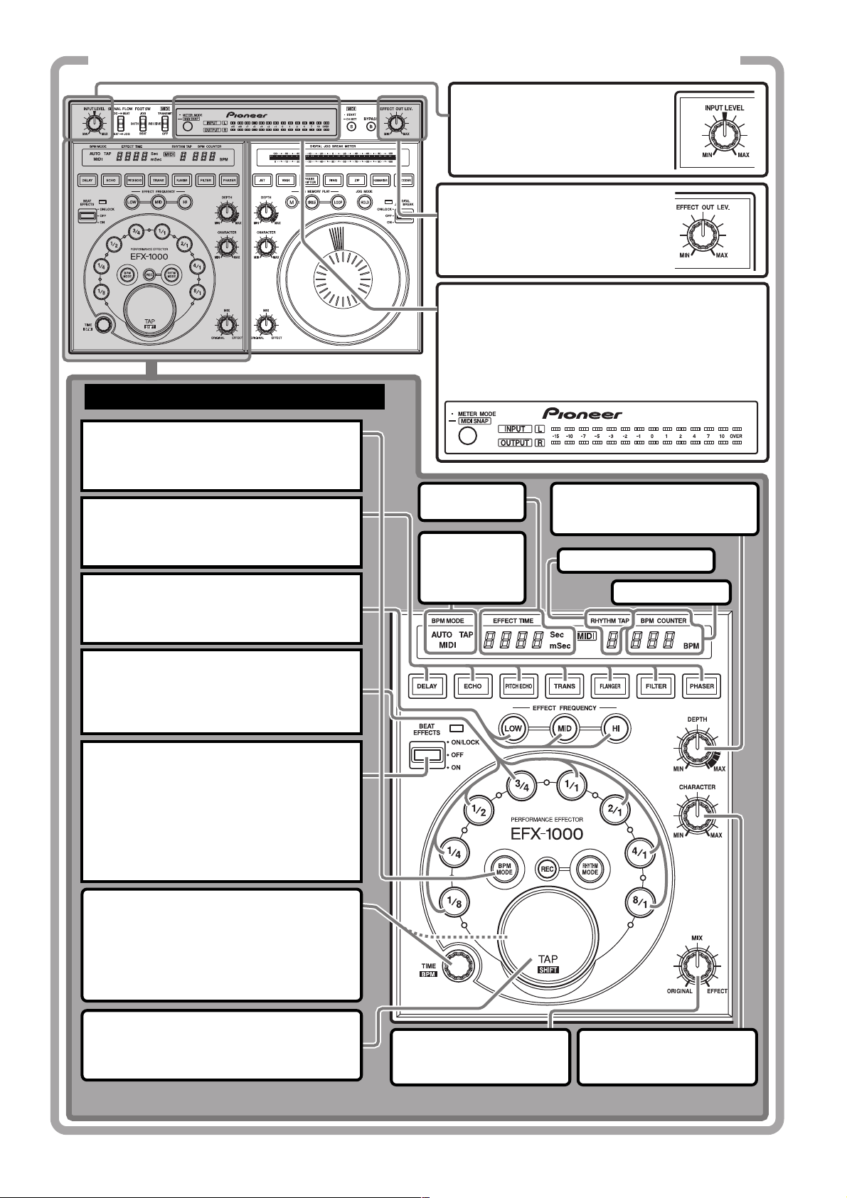
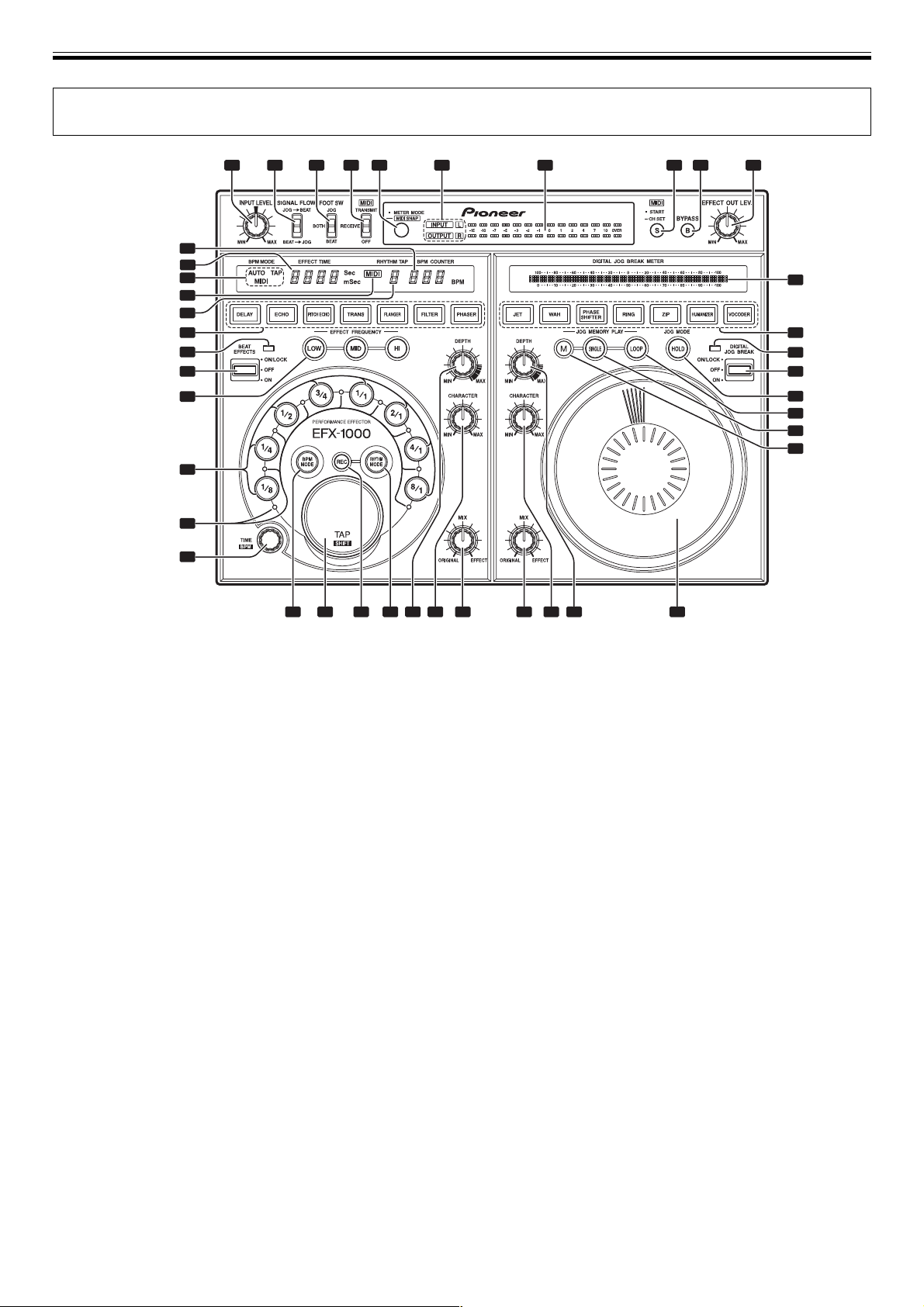
CONTROLS AND FUNCTIONS
1
Control Panel
11
12
13
14
15
16
17
18
19
20
2 3 4 6 7 8 9 10
5
41
40
39
38
37
36
35
34
21
22
23 24 25 26 27 28 29 30 31 32 33
1 INPUT LEVEL dial
Use to adjust the input level. Adjustment range is –∞ to
+9dB with analog inputs, and –∞ to 0dB with digital inputs.
2 SIGNAL FLOW switch
Use to select the order of signal flow between beat effect
and digital jog break sections.
JOG = BEAT:
Signals travel through the digital jog break section before
passing to the beat effect section.
BEAT = JOG:
Signals travel through the beat effect section before
passing to the digital jog break section.
3 Foot switch mode selector (FOOT SW)
Use to select which function is controlled (ON/OFF) by an
attached foot switch (pedal switch).
BEAT:
Attached foot switch controls beat effect function (ON/OFF).
JOG:
Attached foot switch controls digital jog break function
(ON/OFF).
BOTH:
Attached foot switch controls both beat effect function and
digital jog break function (ON/OFF).
4 MIDI mode select switch
Select MIDI communication between computer and other
instruments, etc.
TRANSMIT:
Acts as MIDI controller
RECEIVE:
Effector can be controlled by MIDI signals.
OFF:
Acts as effector (communication OFF)
5 METER MODE/MIDI SNAP button
[Use to switch the function of the level meter display.]
Each time the button is pressed, the level meter display
switches between input and output monaural display,
input stereo display, and output stereo display.
[MIDI Snapshot Mode]
When this button is held depressed with the MIDI mode set
to [TRANSMIT], a snapshot will be sent to the external MIDI
component.
6 Level meter mode display (INPUT, OUTPUT, L, R)
Input and output monaural display:
Both [INPUT] and [OUTPUT] indicators light.
Input stereo display:
[INPUT] and [L], [R] indicators light.
Output stereo display:
[OUTPUT] and [L], [R] indicators light.
7 Level meter display
8 MIDI START/CH SET button / indicator
[MIDI START]
If this button is pressed when MIDI mode is set to
[TRANSMIT], the MIDI start/stop signal is output.
Lights steadily with START, and goes out with STOP.
[MIDI channel setting (CH SET)]
If this button is held depressed when MIDI mode is set to
[TRANSMIT] or [RECEIVE], the MIDI indicator flashes and
the MIDI setting mode is enabled.
14
<DRB1369>

BEFORE USE (CONTROLS AND FUNCTIONS)
9 BYPASS button / indicator
When this button is set to ON, the audio input connector
signals are fed directly to the output connectors, bypassing
the effector circuits.
When the audio input/output connectors are connected
directly in this way, the indicator flashes.
10 EFFECT OUT LEV. dial
When effects are set to ON, this dial can be used to control
the effect output level. Adjustment range is –∞ to +6dB.
Beat Effect section
11 BPM COUNTER display
Displays the beats-per-minute of the input source, or the
TAP input. The indicator flashes during automatic BPM
calculation. When power is first turned on, the counter will
flash [120 BPM].
12 EFFECT TIME display
Displays actual effect time.
When power is first turned on, defaults to [500 mSec].
13 BPM measurement mode display
(AUTO, MIDI, TAP).
Displays the BPM measurement mode.
20 Beat select buttons / indicators
(1/8, 1/4, 1/2, 3/4, 1/1, 2/1, 4/1, 8/1)
[During BPM mode]
When a BPM is measured automatically or input manually,
the beat select button [1/1] is selected by default. The effect
is synchronized automatically to the BPM, and the
corresponding effect time is displayed.
If a beat select button is then pressed, the effect is newly
synchronized to the corresponding multiple of the BPM (1/
8, 1/4, 1/2, 3/4, etc.), thus allowing one-touch change of the
BPM synchronization multiple. In turn, the selected beat
select button lights, thus showing to what multiple of the
actual BPM the effect is synchronized, as well as the
multiple of the time parameter.
[During RHYTHM mode]
When the rhythm input with the TAP button is established,
[1/1] is selected and a multiple of the rhythm can be
selected with the beat select buttons.
21 Beat effect beat-interval indicators
The indicators light to show the period of the effect time.
22 Beat effect TIME/BPM dial
When rotated the effect time selected with the beat select
buttons can be changed as desired.
If the dial is rotated while depressing the TAP button, the
BPM can be set as desired (BPM manual input).
English
14 MIDI display
Lights when handling MIDI data.
15 RHYTHM TAP display
Displays the tap count input in the rhythm mode.
16 Beat effect select button / indicator
(DELAY, ECHO, PITCH ECHO, TRANS, FLANGER,
FILTER, PHASER).
Use to select the beat effect. All buttons light, and selected
effect button flashes.
When power is turned ON, DELAY flashes.
17 BEAT EFFECTS indicator
Lights when beat effects are ON.
18 BEAT EFFECTS lever switch (OFF/ON/ON-LOCK)
Pull the lever toward you [ON] to output beat-effected
sounds.
In the middle position beat effects are [OFF]; push the lever
away from you to lock the lever in the [ON/LOCK] position
(effects are locked ON). When pulled to the [ON] position,
beat effects are output only while the lever is held; when
your finger is released, the lever returns to middle [OFF]
position.
23 BPM MODE button / indicator
Use to turn BPM mode ON, and to select tempo
measurement mode (AUTO/MIDI/TAP). During BPM mode,
the button lights.
If the TAP button is pressed (tapped) during BPM mode,
the mode switches to manual BPM measurement mode.
When power is first turned, the mode defaults to AUTO
measurement mode.
24 TAP/SHIFT button / indicator
[During BPM mode]
When this button is tapped, the BPM manual measurement
mode is selected, and the interval between two taps
(maximum interval 2 seconds) is measured; the
corresponding EFFECT TIME and BPM count is displayed,
and the beat select button [1/1] is selected.
If the TIME/BPM dial is rotated while pressing this button,
the BPM can be adjusted to an optional value (BPM manual
input).
[During RHYTHM mode]
When this button is tapped, the rhythm is input (maximum
tap interval 2 seconds, up to maximum rhythm count 8).
The beat select button [1/1] is selected.
[Tap indicator]
Lights during normal use; goes out only when TAP is
pressed.
19 EFFECT FREQUENCY select buttons (LOW/MID/HI)
Use to select the frequency band of the sounds to which
beat effects will be applied. The button of the selected band
will light.
When power is first turned ON, all three of the ranges LOW,
MID, and HI are selected. If all three range buttons are OFF,
no beat effects will be applied to sounds.
25 Rhythm REC button
Clears the currently input rhythm and allows input of a new
rhythm.
15
<DRB1369>

BEFORE USE (CONTROLS AND FUNCTIONS)
26 RHYTHM MODE button / indicator
When this button is pressed, the RHYTHM mode is
selected, and the button lights.
27 Beat effect DEPTH dial
Allows adjustment of effect feedback and timing
parameters in accordance with the amount of rotation (see
page 13).
28 Beat effect CHARACTER dial
Allows adjustment of parameters other than those set with
the beat effect DEPTH dial (see page 13).
29 Beat effect MIX dial
Rotate to adjust the mixing balance of original and effect
sounds. When rotated fully to the [ORIGINAL] side, the
original (un-effected) sound will be output; as the dial is
rotated toward the [EFFECT] side, the effect sound is
amplified and the original sound decreases.
Digital Jog Break section
30 Digital jog break effect MIX dial
Rotate to adjust the mixing balance of original and effect
sounds. When rotated fully to the [ORIGINAL] side, the
original (un-effected) sound will be output; as the dial is
rotated toward the [EFFECT] side, the effect sound is
amplified and the original sound decreases.
31 Digital jog break effect CHARACTER dial
Allows adjustment of parameters other than those set with
the digital jog break DEPTH dial (see page 13).
32 Digital jog break DEPTH dial
Allows adjustment of effect feedback and timing
parameters in accordance with the amount of rotation (see
page 13).
33 Jog dial
Effect parameters change in response to the rotation of the
dial.
36 Jog memory LOOP play button / indicator
If the button is pressed while the button indicator is lighted,
the parameter change previously recorded in memory in
response to the Jog dial movement is reproduced (played
back repeatedly).
Press again to end Jog memory loop play.
Indicator lights when the jog operation is stored in
memory. Indicator flashes during jog memory loop play
(playback).
37 Jog HOLD button / indicator
When this button is pressed so that its indicator lights, the
effect produced when rotating the Jog dial is maintained
even if you remove your hand from the dial (when the hold
function is OFF, the effect returns to normal if your hand is
removed from the dial). When power is first turned on, the
button defaults to jog hold OFF (indicator is off).
38 DIGITAL JOG BREAK effect lever switch
(OFF/ON/ON-LOCK)
Pull the lever toward you [ON] to output effected sounds.
In the middle position effects are [OFF]; push the lever
away from you to lock the lever in the [ON/LOCK] position
(effects are locked ON). When pulled to the [ON] position,
effects are output only while the lever is held; when your
finger is released, the lever returns to middle [OFF]
position.
39 DIGITAL JOG BREAK effect indicator
Lights when digital jog break effect is ON.
40 Digital jog break effect selector buttons /
indicators (JET, WAH, PHASE SHIFTER, RING,
ZIP, HUMANIZER, VOCODER)
Press to select a desired digital jog break effect. All the
buttons light, and the select effect button flashes.
When power is turned ON, JET flashes.
41 DIGITAL JOG BREAK METER
During operation of the Jog dial, and during jog memory
play, this meter lights to display the corresponding
movement.
34 Jog memory button (M)
If the Jog dial is rotated while holding this button
depressed, the parameter change in response to the
movement is recorded to memory, to a maximum 8
seconds. Recording to memory is not possible during jog
memory play.
35 Jog memory SINGLE play button / indicator
If the button is pressed while the button indicator is lighted,
the parameter change previously recorded in memory in
response to the Jog dial movement is reproduced (played
back) one time only.
Indicator lights when the jog operation is stored in
memory. Indicator flashes during jog memory single play
(playback).
16
<DRB1369>
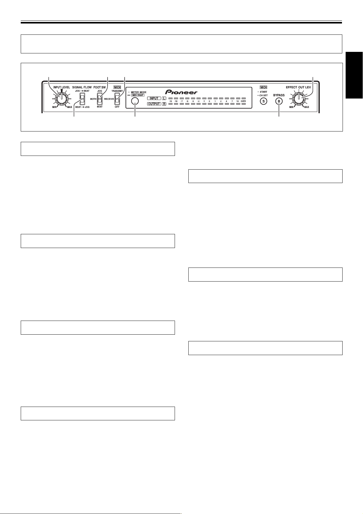
OPERATIONS
INPUT LEVEL FOOT SW MIDI (TRANSMIT/RECEIVE/OFF) EFFECT OUT LEV.
SIGNAL FLOW METER MODE BYPASS
OPERATIONS
English
Adjusting Input Level
Adjust the input level so that the sound is not distorted due
to an excessive input level.
7 Input signals to the input connectors, and rotate the
INPUT LEVEL dial to adjust the level.
¶ Use the METER MODE button to select “input stereo
display” (INPUT, L, R indicators light).
¶ If the proper adjustment cannot be obtained without
rotating the INPUT LEVEL dial to its extreme [MIN] or
[MAX] positions, try changing the position of the rear-panel
IN&OUT LEVEL switch (–10dB / +4dB).
Adjusting Effect Output Level
Adjusts the sound level of the effect applied to the input
sound signal by the beat effect and the digital jog break.
7 Input signals to the input connectors, and rotate the
EFFECT OUT LEV. dial to adjust the effect output level.
¶ Use the METER MODE button to select “output stereo
display” (OUTPUT, L, R indicators light).
¶
When both the BEAT EFFECTS lever switch and the DIGITAL
JOG BREAK lever switch are set to [OFF], the output level is
not changed by turning the EFFECT OUT LEV. dial.
Selecting Signal Flow
¶ When set to the [BEAT] position the foot switch operates to
turn beat effects ON/OFF.
* Use a commercially available switching-type foot switch
with 6.3 mm monaural phone plug.
Selecting the Level Meter Display
This unit’s level meter can be set to display the desired
mode.
7 Press the METER MODE button to select the desired
mode.
¶ Each time the METER MODE button is pressed, the display
switches alternately as follows:
[INPUT] and [OUTPUT] light:
= Input and output level are displayed in monaural.
[INPUT] and [L], [R] light:
= Input level is displayed in stereo.
[OUTPUT] and [L], [R] light:
= Output level is displayed in stereo.
Digital Link Function
Fader Effect Function
When the accessory digital link cable is used to connect
this unit to a DJ mixer (DJM-1000) with digital link support,
send/return connections are completed by a single digital
connection, thus enabling fader effect functions that allow
the DJ mixer’s fader to be used to perform digital jog break.
Select the order in which signal processing occurs (beat
effect or digital jog break)
7 Use the SIGNAL FLOW switch to select the signal
processing order:
¶ When set to the [JOG= BEAT] position, signals are
processed for digital jog break effects first, followed by beat
effects .
¶ When set to the [BEAT= JOG] position, signals are
processed for beat effects first, followed by digital jog break
effects.
Selecting Foot Switch Operation
This effector allows connection of an optional foot switch
(pedal switch) for ON/OFF control of beat effects and digital
jog break effects. Use the foot switch to select the way in
which the foot switch operates.
7 Set the FOOT SW switch to the desired operating
position:
¶ When set to the [JOG] position, the foot switch operates to
turn digital jog break effects ON/OFF.
¶ When set to the [BOTH] position, the foot switch operates to
turn both digital jog break effects and beat effects ON/OFF.
Bypass Function
This function allows signals to be output directly, without
passing through the effects processing circuitry.
7 Press the BYPASS button to make a direct link between
input and output.
¶ When the BYPASS button is pressed, the button flashes and
input signals are output directly, without passing through
the effector circuitry.
¶ When the BYPASS button is flashed, the unit’s controls will
have no effect on the input signals.
17
<DRB1369>
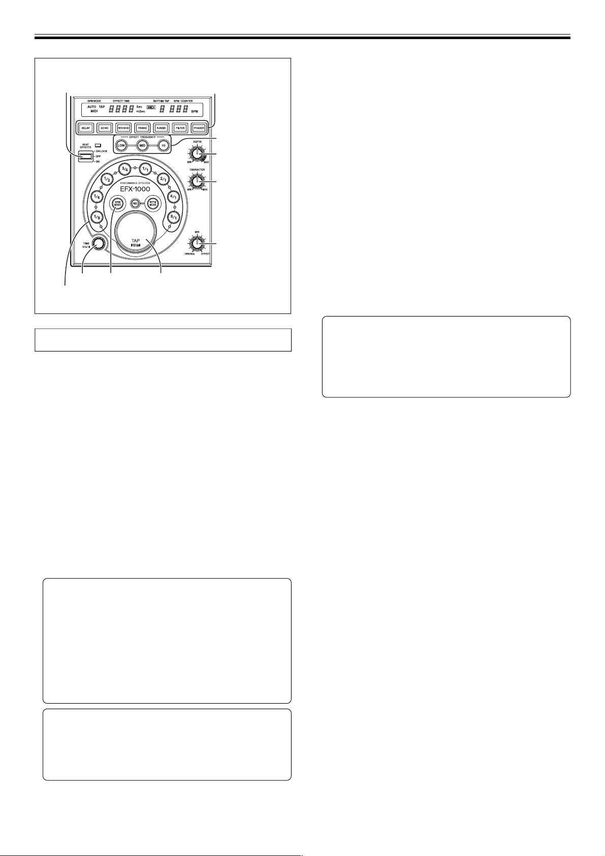
OPERATIONS (Beat Effects [BPM mode])
OPERATIONS (Beat Effects [BPM mode])
2) DELAY, ECHO, PITCH ECHO, TRANS,
5) BEAT EFFECTS
1) BPM MODE
TIME
4) 1/8, 1/4, 1/2, 3/4, 1/1, 2/1, 4/1, 8/1
(beat select)
FLANGER, FILTER, PHASER
(beat effect select)
3) EFFECT
FREQUENCY
LOW, MID, HI
DEPTH
CHARACTER
MIX
TAP
Beat Effects [BPM mode]
Since the beat effect time of the beat effect [BPM mode] can
be synchronized in real-time with the BPM (beats per
minute), you can easily generate effects in time with the
rhythm of a live performance.
1. Press the BPM MODE button to select the BPM (beatsper-minute) measurement mode.
AUTO: BPM is measured automatically from the input music
source.
MIDI: BPM is measured automatically based on the MIDI timing
clock.
TAP: BPM is input manually by tapping on the TAP button.
¶ When power is first turned ON, the mode defaults to AUTO.
¶ The selected mode is shown by the BPM mode indicator.
¶ In the event the input signal cannot be counted properly,
the BPM COUNTER flashes.
¶ The measurement range in the AUTO mode is 70-180 BPM.
Correct measurement may not be possible depending on
the music track; in this event, input the tempo manually
using the TAP mode.
[Manual BPM input using the TAP button]
When the TAP button is tapped two or more times in
time with the beat (quarter notes), the average value
of the intervals is used to set BPM.
¶ When BPM is set to AUTO or MIDI mode, pressing the TAP
button changes the BPM measuring mode to the TAP mode,
and the unit measures the intervals at which the TAP button
is struck.
¶ When BPM is set with the TAP button, the beat select
button [1/1] is selected and the time of 1 beat (quarter
notes) is set to the effect time.
2. Use the beat effect select buttons to select the desired
effect.
¶ Select from DELAY, ECHO, PITCH ECHO, TRANS,
FLANGER, FILTER, or PHASER.
¶ The selected effect button flashes.
¶ See pages 10, 11 regarding each effect.
3. Use the EFFECT FREQUENCY buttons (LOW, MID, HI) to
select the band to which the effect is to be applied.
¶ When a button is pressed, the button’s indicator will light.
¶ Each time a button is pressed, it alternates ON/OFF.
4. Press one beat select button to select the beat with
which the effect is to be synchronized.
¶ Select from 1/8, 1/4, 1/2, 3/4, 1/1, 2/1, 4/1, or 8/1.
¶ The selected beat button lights.
¶ When a beat select button is pressed, the corresponding
effect time is automatically set.
Example: when BPM is 120,
1/1 = 500 ms
3/4 = 375 ms
1/2 = 250 ms
¶ When the beat select button is pressed and the TAP button
is held down, BPM is automatically set from the effect time.
Manual Input of Effect Time Using the TIME Dial
Normally, the effect time is automatically set when a
beat select button is pressed. However, the effect time
can be set as desired using the TIME dial.
¶ When the effect time is changed, the beat select button
lights for the beat automatically set in correspondence to
the new effect time.
5. Pull the BEAT EFFECTS lever switch to ON to appy the
effect.
When pushed away from you to the [ON/LOCK] position:
The switch is locked on, so that the effect continues to be
applied even if you remove your hand from the lever. To stop
the effect, return the lever to the middle position [OFF].
When pulled toward you to the [ON] position:
The effect is applied only while the lever is pulled to the [ON]
position; when the lever is released, it returns automatically to
the middle [OFF] position. Use this function when you wish to
alternate rapidly between ON and OFF.
DEPTH dial
Set to the center center indent position for standard effect sounds.
For more information regarding the change in parameter 1 in
response to DEPTH dial rotation, see pages 10, 11, 13.
CHARACTER dial
Set to the center center indent position for standard effect sounds.
For more information regarding the change in parameter 2 in
response to CHARACTER dial rotation, see pages 10, 11, 13.
MIX dial
Use to adjust the mixing balance of original and effect sounds. Set
to the center indent position for standard effect sounds.
[Manual BPM input using the TIME dial]
BPM can be directly set by turning the TIME dial when
the TAP button is held down.
¶ BPM can be set in 0.1 increments by pressing the BPM MODE
button and turning the TIME dial while holding down the TAP
button. Only decimal values are shown at this time.
18
<DRB1369>
2) DELAY, ECHO, PITCH ECHO, TRANS,
7) BEAT EFFECTS
TIME
6) 1/8, 1/4, 1/2, 3/4, 1/1, 2/1, 4/1, 8/1
(beat select)
FLANGER, FILTER, PHASER
(beat effect select)
BPM MODE 1) RHYTHM MODE
5) TAP
3) EFFECT
FREQUENCY
LOW, MID, HI
DEPTH
CHARACTER
MIX
4) Rhythm REC
Operations (Beat Effects [RHYTHM mode])
6. Select one of the beat select buttons to establish the
overall time for the input rhythm.
¶ The overall time for the input rhythm will be multiplied in
response to the selected button.
¶ Select from 1/8, 1/4, 1/2, 3/4, 1/1, 2/1, 4/1, or 8/1.
¶ The selected beat button lights.
7. Pull the BEAT EFFECTS lever switch to ON to appy the
effect.
When pushed away from you to the [ON/LOCK] position:
The switch is locked on, so that the effect continues to be
applied even if you remove your hand from the lever. To stop
the effect, return the lever to the middle position [OFF].
When pulled toward you to the [ON] position:
The effect is applied only while the lever is pulled to the [ON]
position; when the lever is released, it returns automatically to
the middle [OFF] position. Use this function when you wish to
alternate rapidly between ON and OFF.
¶ If the Rhythm REC button is pressed during the rhythm
mode, the input rhythm will be cleared and rhythm input
mode is once again enabled.
DEPTH dial
Set to the center center indent position for standard effect sounds.
For more information regarding the change in parameter 1 in
response to DEPTH dial rotation, see pages 10, 11, 13.
English
Beat Effects [RHYTHM mode]
The beat effects [RHYTHM mode] function allows you to
create a variety of effects synchronized with your own
input rhythm.
1. Use the RHYTHM MODE button to set to rhythm mode.
¶ The RHYTHM MODE button lights.
2. Use the beat effect select buttons to select the desired
effect.
¶ Select from DELAY, ECHO, PITCH ECHO, TRANS,
FLANGER, FILTER, or PHASER.
¶ The selected effect button flashes.
¶ See pages 10, 11 regarding each effect.
3. Use the EFFECT FREQUENCY buttons (LOW, MID, HI) to
select the band to which the effect is to be applied.
¶ When a button is pressed, the button’s indicator will light.
¶ Each time a button is pressed, it alternates ON/OFF.
4. Press rhythm REC button to set to REC mode.
¶ The BPM display will indicate “ ”.
¶ If no rhythm has been input, the unit will automatically
enter the REC mode in step 1.
5. Input the desired rhythm using the TAP button.
¶ Input taps will be recognized as a tempo when occurring at
intervals of less than 2 seconds. Up to 8 taps can be input.
¶ The counted taps (RHYTHM TAP) will be shown in the
display.
¶ During rhythm input, the beat select button [1/1] will be
selected.
CHARACTER dial
Set to the center center indent position for standard effect sounds.
For more information regarding the change in parameter 2 in
response to CHARACTER dial rotation, see pages 10, 11, 13.
MIX dial
Use to adjust the mixing balance of original and effect sounds. Set
to the center indent position for standard effect sounds.
19
<DRB1369>
OPERATIONS (Digital Jog Break)
1) JET, WAH, PHASE SHIFTER,
RING, ZIP, HUMANIZER, VOCODER
(Jog effect select)
2) DIGITAL JOG BREAK
MIX dial
Use to adjust the mixing balance of original and effect sounds. Set
to the center indent position for standard effect sounds.
HOLD Function
When the HOLD button is pressed and lit, the effect generated by
the rotation of the Jog dial continues when the dial rotation stops.
DEPTH
CHARACTER
MIX
Jog memory (M)
Jog dial
HOLD
LOOP
SINGLE
Digital Jog Break
Since the digital jog break can continuously change the
parameters of each effect generated by rotating the Jog
dial, the effects can be controlled like a musical instrument.
Further, by using the jog memory function, the continuously
changing effect sound can be stored in memory, and later
played back by pressing one of the JOG MEMORY PLAY
buttons (SINGLE or LOOP).
1. Use the Jog effect select buttons to select the desired
effect.
¶ Select from JET, WAH, PHASE SHITER, RING, ZIP,
HUMANIZER, or VOCODER.
¶ The selected Jog effect button flashes.
¶ See page 12 regarding each effect.
2. Set the DIGITAL JOG BREAK lever switch to ON and
turn the Jog dial.
[DIGITAL JOG BREAK Lever switch operation]
When pushed away from you to the [ON/LOCK] position:
The switch is locked on, so that the effect continues to be
applied even if you remove your hand from the lever. To stop
the effect, return the lever to the middle position [OFF].
When pulled toward you to the [ON] position:
The effect is applied only while the lever is pulled to the [ON]
position; when the lever is released, it returns automatically to
the middle [OFF] position. Use this function when you wish to
alternate rapidly between ON and OFF.
¶ Parameter changes caused by rotating the Jog dial are
indicated on the DIGITAL JOG BREAK METER.
Jog Memory
Up to 8 seconds of the digital jog break’s jog dial
movement can be stored in memory, and the effect later
played back at a single touch.
1. Use the Jog effect select buttons to select the desired
effect.
¶ Select from JET, WAH, PHASE SHITER, RING, ZIP,
HUMANIZER, or VOCODER.
¶ The selected Jog effect button flashes.
¶ See page 12 regarding each effect.
2. Set the DIGITAL JOG BREAK lever switch to ON to
monitor the effect.
3. Turn the Jog dial while holding down the Jog memory
button (M).
Turning the Jog dial while the M button is held down starts
memory storage. Effects are stored continues for 8 seconds or
until the M button is released. The SINGLE or LOOP button
lights.
¶ When an effect has already been stored in memory
(SINGLE button and LOOP button are lighted), if a new
effect is stored in memory, the previously stored contents
will be overwritten and the effect data will be erased.
4. Press the SINGLE or LOOP button.
¶ When the SINGLE button is pressed, the button flashes and
the stored effect produced by the jog dial movement is
played back one time.
¶ When the LOOP button is pressed, the button flashes and
the stored effect produced by the jog dial movement is
played back repeatedly. Press the LOOP button once again
to stop the effect playback.
¶ Jog dial operation stored in memory can be reproduced
even when the type of effect is subsequently changed.
DEPTH dial
Set to the center center indent position for standard effect sounds.
For more information regarding the change in parameter 1 in
response to DEPTH dial rotation, see pages 12, 13.
CHARACTER dial
Set to the center center indent position for standard effect sounds.
For more information regarding the change in parameter 2 in
response to CHARACTER dial rotation, see pages 12, 13.
20
<DRB1369>
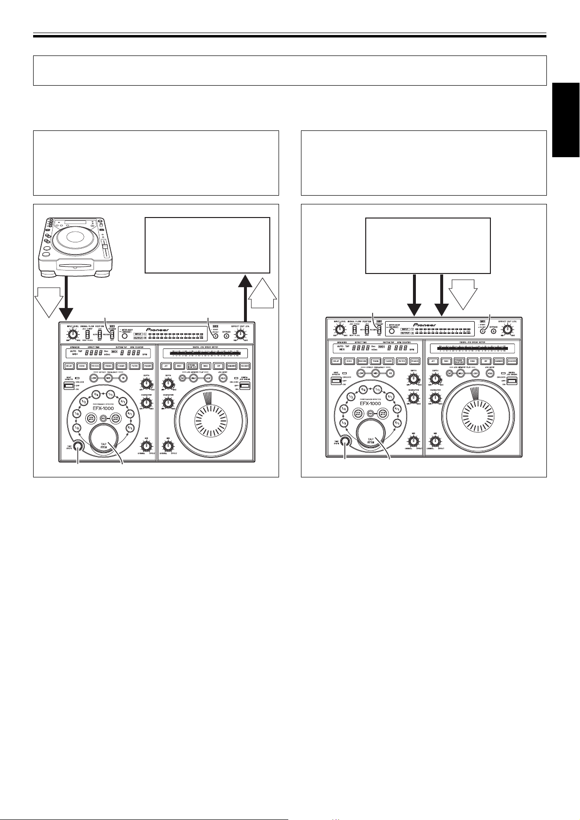
MIDI SETTINGS
MIDI SETTINGS
MIDI (Musical Instrument Digital Interface) is a standard protocol designed to allow exchange of information between electronic
instruments and/or computers. A MIDI cable is used to connect two appliances equipped with MIDI connectors, thus allowing data to be
exchanged between the two appliances. The EFX-1000 uses MIDI to send and receive operation and BPM data (timing clock).
Synchronizing an external
sequencer to an audio signal, or
using EFX-1000 operation data to
operate an external sequencer
DJ CD player
MIDI sequencer
OUT
BPM
=120
Audio
MIDI TRANSMIT/
RECEIVE/OFF
MIDI
MIDI START/
CH SET
OUTIN
IN
BPM
=120
To synchronize beat effects to
external sequencer, or use an
external sequencer to operate the
EFX-1000
MIDI sequencer
MIDI TRANSMIT/
RECEIVE/OFF
Audio
OUTOUT
MIDI
BPM
=120
MIDI START/
ININ
CH SET
English
TIME TAP
EFX-1000
1. Use a commercially available MIDI cable to connect the
EFX-1000’s MIDI OUT connector and the MIDI
sequencer’s MIDI IN connector.
¶ The MIDI sequencer’s sync mode should be set to slave.
¶ MIDI sequencers which do not support MIDI timing clock
cannot be synchronized.
2. Set MIDI switch to [TRANSMIT] position.
¶ Sync cannot be performed in the case of tracks whose BPM
values cannot be measured stably.
¶ Timing clock is also output for BPM values set by using the
TAP mode.
3. Press the MIDI START/CH SET button.
¶ MIDI timing clock output range is 40-250 BPM.
[Setting TRANSMIT MIDI channel]
The TRANSMIT channel can be set and recorded in memory
separately from the RECEIVE channel.
1. Set MIDI switch to [TRANSMIT] position.
2. In this condition, hold the MIDI START/CH SET button
depressed.
¶ The MIDI indicator will flash and the setting mode will be
enabled.
3. Rotate the TIME dial to select MIDI channel.
4. Press the MIDI START/CH SET button.
¶ The MIDI channel will be recorded, and the unit will leave
the setting mode.
NOTE:
It may not be possible to set BPM correctly with some tracks.
TIME TAP
EFX-1000
1. Use a commercially available MIDI cable to connect the
MIDI sequencer’s MIDI OUT connector to the EFX-1000’s
MIDI IN connector.
¶ Adjust controls for optimum instrument input/output levels.
¶ Set all effect switches to OFF.
¶ Set BYPASS switch to OFF.
2. Set the MIDI switch to the [RECEIVE] position.
¶ The MIDI OUT/THRU connector will throughput (output) the
same signal that was input.
3. Start the MIDI sequencer.
¶ Even during use of sequencer control, the EFX-1000 can be
controlled directly if desired, but depending on the volume,
the set parameter values may jump at the instant an
operation is performed, so caution is needed.
¶ The range that the MIDI timing clock can accept is 40-250
BPM.
[Setting the RECEIVE MIDI channel]
The RECEIVE channel can be set and recorded in memory
separately from the TRANSMIT channel.
1. Set MIDI switch to [RECEIVE] position.
2. In this condition, hold the MIDI START/CH SET button
depressed.
¶ The MIDI indicator will flash and the setting mode will be
enabled.
3. Rotate the TIME dial to select the MIDI channel, then
press the TAP button to confirm.
NOTE:
If the MIDI sequencer’s BPM is set in 0.1 units, it may not match the
BPM display on the EFX-1000.
<DRB1369>
21
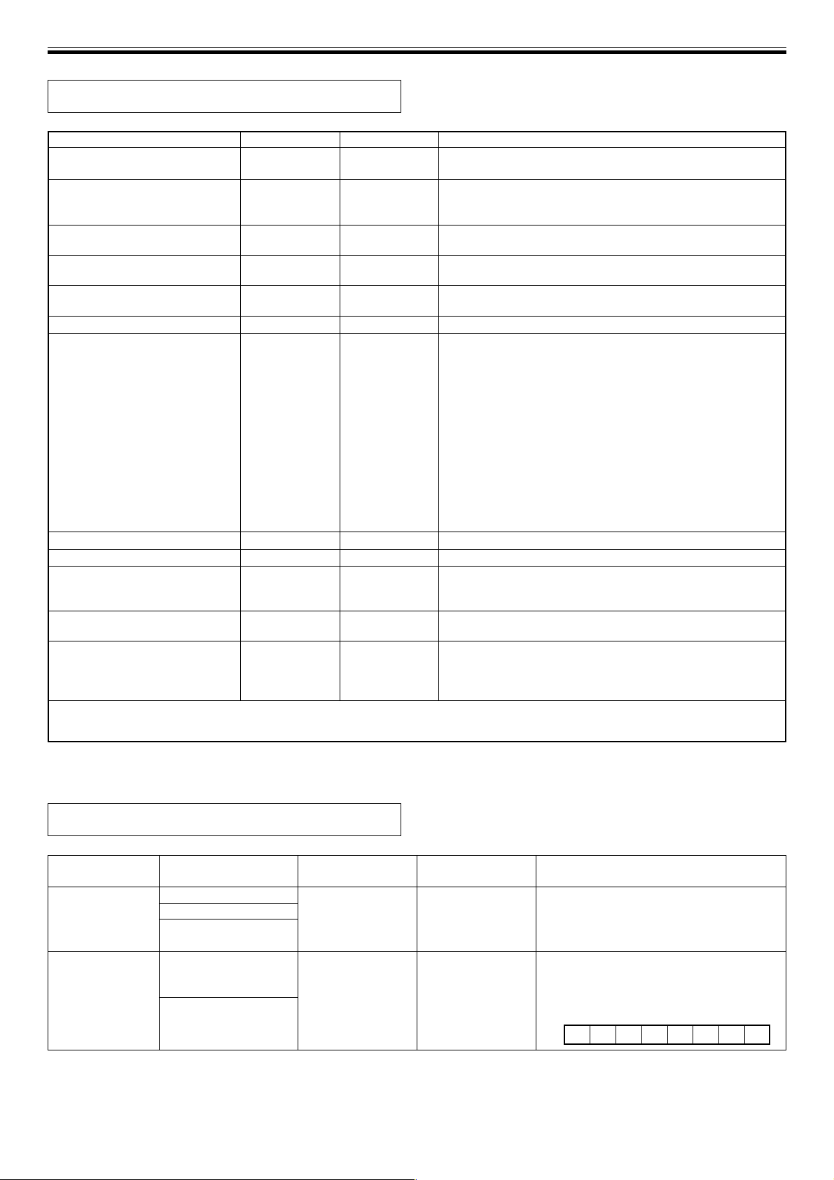
MIDI SETTINGS
MIDI Implementation Chart
Function
Basic channel: When power ON
Settable range
When power ON
Mode: Message
Replacement
Note number:
Sound range
Velocity: Note ON
Note OFF
After touch: By Key
By Channel
Pitch Bender:
12, 44
13, 45
16, 48
17, 49
64
66
Control change: 67
69
80
81
82
83
91
92
Program change: setting range
Exclusive:
Song position
Common: Song select
Tune
Real time: Clock
Command
Local ON/OFF
Other: All Note/OFF
Active sensing
Reset
Comments:
Transmit
1-16
1-16
Mode 3
✕
✕
✕
✕
✕
✕
✕
✕
‡
‡
‡
‡
‡
‡
‡
‡
‡
‡
‡
‡
‡
‡
‡
✕
✕
✕
✕
‡
‡
✕
✕
✕
✕
Receive
1-16
1-16
Mode 3
✕
✕
✕
✕
✕
✕
✕
✕
‡
‡
‡
‡
‡
‡
‡
‡
‡
‡
‡
‡
‡
‡
‡
✕
✕
✕
✕
‡
✕
✕
✕
✕
✕
Comments
Stored in memory
Beat select time parameter (MSB, LSB)
Time parameter (MSB, LSB)
JOG parameter (MSB, LSB)
Rhythm parameter 1 (MSB, LSB)
Effect ON/OFF
Frequency select
Rhythm parameter 2
Beat Operation Mode
VR parameter 1
VR parameter 2
VR parameter 3
VR parameter 4
VR parameter 5
VR parameter 6
Transmit: start/stop
Mode 1: Omni, ON, Poly Mode 2: Omni, ON, Mono ‡: Yes
Mode 3: Omni, OFF, Poly Mode 4: Omni, OFF, Mono ✕: No
Control Change (CC) Table
Function
Effect type
switching
Effect ON/OFF
22
<DRB1369>
EFX-1000 Operation
Signal flow change
Beat effect select
Digital jog break
Effect select
Beat effect (ON/OFF)
Digital jog break
Effect (ON/OFF)
Message
(Command)
ProgramChange
Hold 1
Format (Hex)
Cn pc
Bn 40 0b
Comments
See program change below.
Sets effect ON/OFF.
b: Effect ON/OFF (ON = 1)
Bit0 JOG
Bit1 BEAT
MSB LSB
000000
BEAT JOG
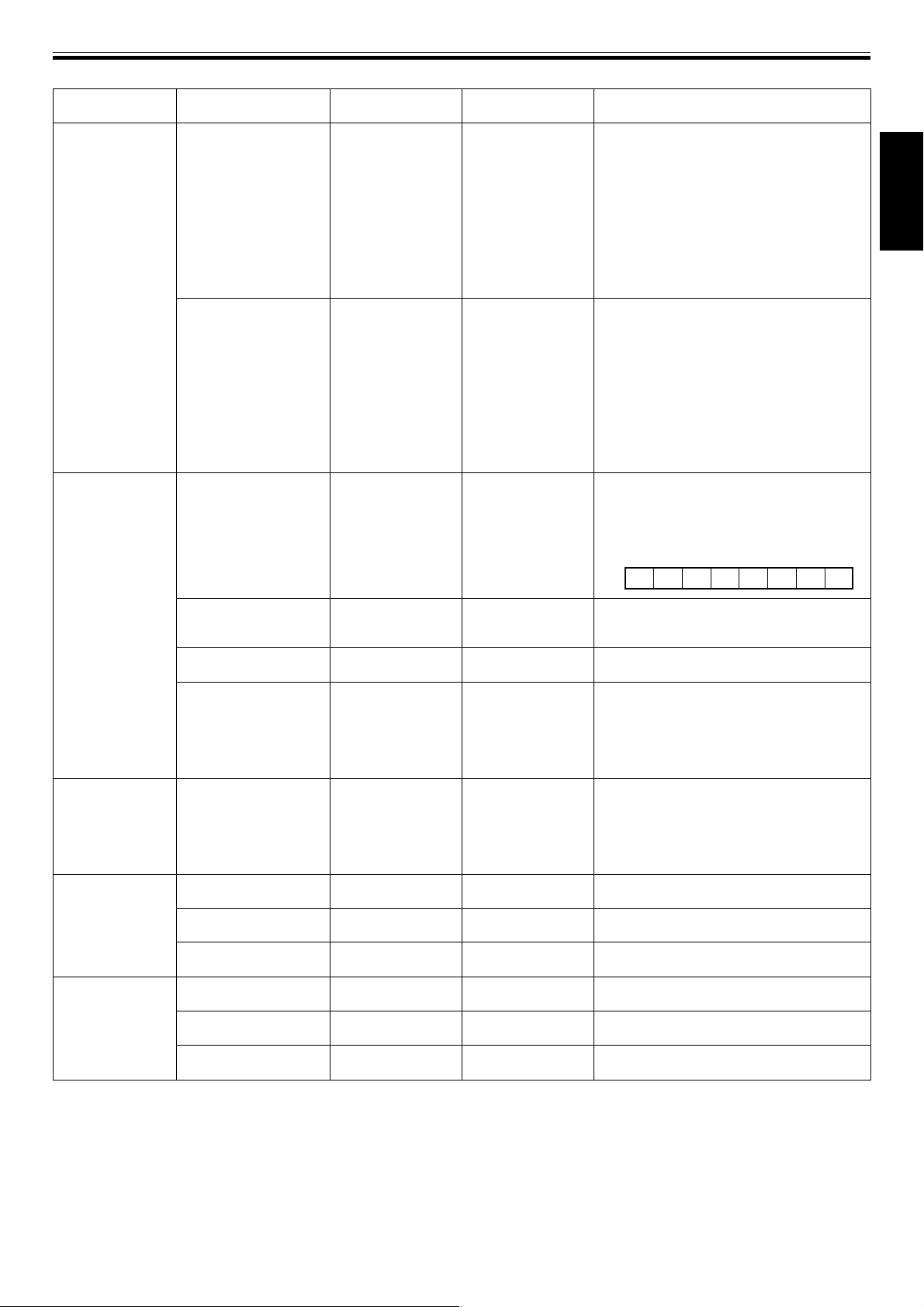
MIDI SETTINGS
Function
Effect time
operation
EFX-1000 Operation
Beat select
TIME dial
Effect frequency select
Message
(Command)
Effect Control 1
Effect Control 2
sostenuto
Format (Hex)
Bn 0c MSB
Bn 2c LSB
Bn 0d MSB
Bn 2d LSB
Bn 42 0b
Comments
Sets effect time.
Setting range (unit: mSec)
DELAY, ECHO, PITCH ECHO: 1-16000
TRANS: 10-16000
FLANGER, FILTER, PHASER: 5-16000
When 5-16000 are transmitted for FLANGER,
FILTER, or PHASER, EFX-1000 internally
multiplies value by x2, so as to operate at 10-
32000.
* On receive side, search is performed for
beginning of effect cycle.
Sets effect time.
Setting range (unit: mSec)
DELAY, ECHO, PITCH ECHO: 1-16000
TRANS: 10-16000
FLANGER, FILTER, PHASER: 5-16000
When 5-16000 are transmitted for FLANGER,
FILTER, or PHASER, EFX-1000 internally
multiplies value by x2, so as to operate at 10-
32000.
* On receive side, search is not performed
for beginning of effect cycle.
Sets frequency range subjected to effect
b: frequency range (ON = 1)
Bit0 LOW
Bit1 MID
Bit2 HI
MSB LSB
00000HIMID
LOW
English
Beat operation
Jog operation
Beat volume
Jog volume
Rhythm TAP
(rhythm time)
Rhythm TAP
(rhythm no.)
BPM mode SW
Rhythm mode SW
Rhythm REC
Jog dial
Beat effect DEPTH
Beat effect CHARACTER
Beat effect MIX
Digital jog break DEPTH
Digital jog break
CHARACTER
Digital jog break MIX
General Purpose
Controller 2
soft pedal
hold 2
General Purpose
Controller 1
Effect 1 Depth
General Purpose
Controller 5
General Purpose
Controller 6
Effect 2 Depth
General Purpose
Controller 7
General Purpose
Controller 8
Bn 11 MSB
Bn 31 LSB
Bn 43 dd
Bn 45 dd
Bn 10 MSB
Bn 30 LSB
Bn 5B dd
Bn 50 dd
Bn 51 dd
Bn 5C dd
Bn 52 dd
Bn 53 dd
Sets tap time interval for rhythm effect.
Setting range (unit: mSec)
1-2000
Sets tap number for rhythm effect.
Setting range: 1-8
Changes Beat operating mode.
1=BPM mode
2=Rhythm mode
During rhythm mode, if rhythm mode is set
again, the recorded rhythm effect will be
canceled and new rhythm data can be input.
Sets jog dial movement.
Setting range: 0-2160
Jog center position is considered 1080; when
dial is rotated clockwise, changes to
maximum 2160; when dial is rotated
counterclockwise, changes to minimum 0.
Sets beat DEPTH value.
Setting range: 0-127
Sets beat CHARACTER value.
Setting range: 0-127
Sets beat MIX value.
Setting range: 0-127
Sets Jog DEPTH value.
Setting range: 0-127
Sets jog CHARACTER value.
Setting range: 0-127
Sets jog MIX value.
Setting range: 0-127
23
<DRB1369>
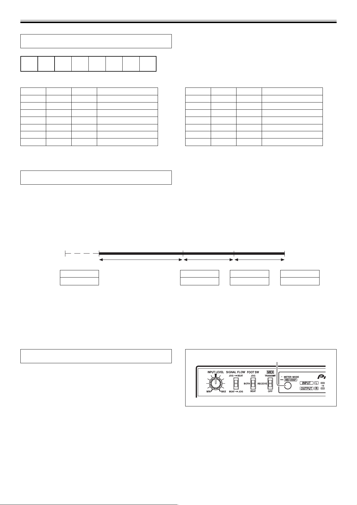
MIDI SETTINGS
Program Change
MSB LSB
SIGNAL
FLOW
0 JOG1BEAT2 BEAT0BEAT1 JOG2
JOG0
¶ SIGNAL FLOW
0 = BEAT EFFECTS = JOG BREAK
1 = JOG BREAK = BEAT EFFECTS
¶ BEAT EFFECTS
BEAT2
0
0
0
1
1
1
1
Use general purpose 8 for setting filters
BEAT1
0
1
1
0
0
1
1
BEAT0
1
0
1
0
1
0
1
DELAY
ECHO
PITCH ECHO
TRANS
FLANGER
FILTER
PHASER
¶ JOG BREAK
JOG2
0
0
0
1
1
1
1
JOG1
JOG0
0
1
1
0
0
1
1
1
0
1
0
1
0
1
JET
WAH
PHASE SHIFTER
RING
ZIP
HUMANIZER
VOCODER
About Rhythm Effects
(Example shown is 3 rhythms)
During TRANSMIT:
Each time rhythm TAP is struck, data is transmitted in the order rhythm parameter 2 (rhythm No.) and rhythm parameter 1
(rhythm time).
Effector operation
TAP TAP TAP TAPRHYTHM MODE button
time 1 time 2 time 3
MIDI data
Beat section
Rhythm mode
Rhythm No. 1
time 1
Rhythm No. 2
time 2
Rhythm No. 3
time 3
During RECEIVE:
¶ During beat effect, if beat operation mode (rhythm mode) is received, the rhythm effect function is enabled.
Thereafter, if the first time rhythm No. 1, time 1, rhythm No. 2, time 2, rhythm No. 3, time 3 are transmitted in that order,
the effector continues to operate in response to the received rhythm.
¶ During rhythm effect, if the beat operation mode (BPM mode) is transmitted, the function returns to beat effect.
Snapshot
Once the effector is set to a target value, a snapshot of that
state can be taken. When snapshot is used, all commands
for control change are transmitted at once.
When setting [TRANSMIT], hold the METER MODE/MIDI
SNAP button depressed to transmit the snapshot. When
this is done the MIDI indicator will flash.
METER MODE/MIDI SNAP
24
<DRB1369>
 Loading...