

Page 1
Order Number: MGCS011201C0
H21 (H22 for USA)
Digital Imaging Systems
DP-1510P / 1810P /
1810F / 2010E
WARNING
!
This service information is designed for experienced repair technicians only and is not intended for use by the general public.
It does not contain warnings or cautions to advise non-technical individuals of potential dangers in attempting to service a product.
Products powered by electricity should be serviced or repaired only by experienced professional technicians. Any attempt to service
or repair the product or products dealt within this service information by anyone else could result in serious injury or death.
© 2002 Matsushita Graphic Communication Systems, Inc.
All rights reserved. Unauthorized copying and distribution is
a violation of law.
Published in Japan.
The contents of this Service Manual are subject to change
without notice.
Page 2

The contents of this Service Manual are subject to change without notice.
Published in Japan.
2
Page 3

Table of Contents
Specifications Table................................5
1.1. Copy Function...........................................5
1.2. Fax, Printer and Internet Fax
Functions................................................14
1.3. System Combination ..... ....... ...... ....... ......23
1.4. Option and Supply Lists..........................26
1.5. External View..........................................27
1.6. Control Panel..........................................30
Disassembly Instructions.....................32
2.1. General Disassembly Flowchart.............32
2.2. Disassembly Instructions........................35
2.3. Screw Identification Template.................86
Maintenance, Adjustments and
Check Points..........................................88
3.1. Required Tools ......................................88
3.2. Periodic Maintenance Points ..................88
3.3. Periodic Maintenance Check List ...........90
3.4. Updating the Firmware ...........................92
3.5. Glossary of Electrical Abbreviations.......96
3.6. SC PC Board... ....... ...... ....... ...... ....... ....107
3.7. PNL6-1 PC Board.................................152
3.8. PNL6-2 PC Board.................................157
3.9. PNL2 PC Board ....................................158
3.10. LPC3 PC Board ....................................159
3.11. ADF PC Board......................................174
3.12. CCD PC Board .....................................178
3.13. LSU PC Board ......................................179
3.14. HTC PC Board......................................180
3.15. HVPS....................................................182
3.16. LVPS.....................................................183
3.17. ILS PC Board........................................184
3.18. INV PC Board .......................................185
3.19. LFB PC Board.......................................186
3.20. SNS PC Board......................................187
3.21. MJR PC Board......................................188
3.22. CST4 PC Board....................................189
3.23. LANB PC Board....................................192
3.24. LANC PC Board....................................193
3.25. EP PC Board ........................................194
3.26. SRU PC Board (Optional).....................195
Troubleshooting .................................. 196
4.1. Initial Troubleshooting Flowchart..........196
4.2. Improper LCD Display ..........................197
4.3. Printed Copy Quality Problems............198
4.4. Document Feeder (ADF)...................... 215
4.5. Troubleshooting the LAN Interfa ce ...... 219
4.6. Error Codes (For Copier) .....................227
4.7. Information Codes Table
(For Facsimile) ..................................... 233
4.8. Diagnostic Codes (For Facsimile)........ 239
4.9. Troubleshooting
(For PCL 6 Emulation Kit) ....................246
Service Modes .....................................248
5.1. Service Modes (For Copier).................248
5.2. Service Modes (For Fax)......................272
System Description.............................314
6.1. Mechanical Operation ..........................314
6.2. Automatic Document Feeder ...............316
6.3. Inverting Automatic Document
Feeder.................................................. 318
6.4. Receive Mechanism.............................320
6.5. Electrical Circuit Explanation................331
Installation............................................353
7.1. Precautions During Set Up...................353
7.2. Unpacking ............................................ 353
7.3. Installation Procedure ..........................353
7.4. Adjustment ........................................... 357
Options and Supplies..........................359
8.1. Installing the 10/100 Ethernet Interface
/ Internet Fax Kit (DA-NE200) ..............359
8.2. Installing the PCL6 Emulation Kit
(DA-PC210)..........................................362
8.3. Installing the Sorting Image Memory
8/16/64/128 MB
(DA-SM08B/16B/64B/28B)...................364
8.4. Installing the Automatic Document
Feeder (DA-AS180)
for DP-1510P/1810P/2010E................. 365
8.5. Installing the Inverting Automatic
Document Feeder (DA-AR201)
for DP-2010E ............................ ...... ..... 370
8.6. Installing the 2nd/3rd/4th Paper Feed
Module (DA-DS182/183)......................376
8.7. Installing the Handset Kit .....................391
8.8. Installing th e Dehumidifier Heat er Kit...392
8.9. Installing the Key Counter Cable Kit
(DA-KH200)..........................................401
8.10. Replacing the OPC Drum.....................403
3
Page 4

Table of Contents
Schematic Diagram .............................406
9.1. General Circuit Diagram System
Circuit....................................................406
9.2. SC PC Board... ....... ...... ....... ...... ....... ....411
9.3. LPC3 PC Board ....................................441
9.4. ADF PC Board........................... ....... ....448
9.5. CCD PC Board .....................................450
9.6. CST4 PC Board....................................451
9.7. PNL6 PC Board ....................................452
9.8. PNL2 PC Board ....................................456
9.9. HTC PC Board (120V)..........................458
9.10. HTC PC Board (230V)..........................459
9.11. WTS PC Board .....................................460
9.12. LFB PC Board.......................................461
9.13. SNS PC Board......................................462
9.14. MJR PC Board (For DP-1810F Only) ...463
9.15. SDRM PC Board...................................464
9.16. LANB PC Board......................... ...........465
9.17. LANC PC Board....................................475
9.18. EP PC Board ........................................476
9.19. FRM PC Board .....................................484
4
Page 5

1 Specifications Table
Note:
DP-1510P/2010E model is limited to certain destinations only.
1.1. Copy Function
DP-1510P/1810P
/1810F/2010E
Items
Basic Specifications
1 Type Desktop
2Platen Fixed
3 Original Position Left / Inner
4 Recording Paper Path Center
5 Face Up / Face Down Face Down
6 Drum Organic Photo Conductor (OPC)
7 Copy Process Dry Electrostatic System
8 Developing Process
9 Toner Recycle No
10 Fusing System Heat & Pressure
11 Max Original Size
12 Paper Size
Paper Tray
Sheet Bypass
Sheet Bypass Envelope No
13 Warm-up Time Approx. 30 sec. 68 °F (20 °C)
14 First Copy Time 6.5 sec.
15 Copy Speed
Ledger / A3 10 cpm
Legal / B4, FLS 11 cpm
Letter-R / A4-R 13 cpm
LTR / A4 15 cpm 18 cpm 20 cpm
Invoice / A5 15 cpm 18 cpm 20 cpm
16 Zoom
Enlargement Select ed Origi nal Size / Copy Size
Reduction Selected Original Size / Copy Size
Zoom 50 - 200% 1% Step
X-Y Zoom No
DP-1510P DP-1810P DP-1810F DP-2010E
Magnetic Mono Component Development
LDR, LGL, LTR, LTR-R, INV-R For USA and Canada
A3, B4, A4, A4-R, A5-R, FLS For EU
A3, B4, A4, A4-R, B5, B5-R For Other Destinations
LDR, LGL, LTR, LTR-R, INV-R For USA and Canada
A3, B4, A4, A4-R, A5-R, FLS For EU
A3, B4, A4, A4-R, B5, B5-R For Other Destinations
Description
System
Ledger (11 x 17 in) /
A3 (297 x 420 mm)
From Platen/ Letter/ A4
Portrait/ 1st Paper Tray.
Period between Start Key
is pressed and Paper exit.
Remarks
Edition 2.0
5
APR 2002
Page 6

DP-1510P/1810P
/1810F/2010E
Items
DP-1510P DP-1810P DP-1810F DP-2010E
Description
Remarks
17 Paper Feed Front Loading Universal Paper Tray
Paper Tray
Capacity
(DP-2010E-PU: 550 sheets x 2)
550 sheets x 1
LTR / A4 : 20 lb (75 g/m
Auto Size Setting No (Input from Control Panel)
Low Paper Warning Empty Only
Sheet Bypass
Capacity 50 sheets
LTR / A4 : 20 lb (75 g/m
Auto Size Setting Yes
Paper Capacity
(Std. Configuration)
600 sheets
Paper Tray + Sheet
Bypass
18 Multi Copy Range 1 - 999 sets
19 Gradation
Text 2-steps
Text / Photo 2-steps Error Diffusion
Photo 256-steps
20 Resolution 600 dpi Scanning and Printing.
St andard Sorting Memory
21
Size
St andard Page Memory
22
Size
No 8 MB
16 MB
23 Exit Tray Capacity Standard: 250 sheets
24 Color No
25 Max Power Consumption Less than 1.2 kW
26 Dimensions
(W x D x H)
23.1 x 23.8 x 16.1 in
(588 x 605 x 410 mm)
23.1 x
23.8 x
20.7 in
(588 x 605
H: To Platen Glas s.
For USA and Canada
x 526 mm)
(W x D x H)
23.1 x 23.8 x 16.1 in
(588 x 605 x 410 mm)
23.1 x 23.8 x 18.0 in
(588 x 605 x 458 mm)
23.1 x 23.8 x 18.0 in
(588 x 605 x 458 mm)
23.1 x
23.8 x
20.6 in
(588 x 605
x 522 mm)
23.1 x
23.8 x
22.6 in
(588 x 605
x 573 mm)
23.1 x
23.8 x
20.6 in
(588 x 605
For Other Destinations
H: Up to i-ADF.
For USA and Canada
For Other Destinations
x 522 mm)
27 Projection Area Less than 3.85 ft / 0.358 m
28 Occupancy Area
(W x D)
33.8 x 23.8 in
(858 x 605 mm)
Includes Sheet Bypass.
2
)
2
)
Edition 2.0
6
APR 2002
Page 7

DP-1510P/1810P
/1810F/2010E
Description
99 lb
(45 kg)
99 lb
(45 kg)
113 lb
(51kg)
93 lb
(42 kg)
Remarks
Main Unit only.
For USA and Canada
For Other Destinations
29 Weight
Items
DP-1510P DP-1810P DP-1810F DP-2010E
91 lb (41 kg)
91 lb (41 kg)
Options
1 Paper Feed System Max. 550 sheets x 2 Max. 550 sheets x 4
550 sheets 2nd/4th
Paper Feed Module
550 sheets 3rd
Paper Feed Module
Yes* Yes
No Yes
Motor is Not Mounted.
*2nd Only
Paper Size Detection Manual (Control Panel)
Low Paper Warning Empty Only
Max. Paper Capacity 1,150 sheets 2,250 sheets
LTR / A4 : 20 lb (75 g/m
2 Cabinet
Stand for
2-Paper Tray
Configuration
Stand for
1-Paper Tray
Option
Depends on the Local
Sales Company.
Option
Configuration
3 Platen Cover Yes No Yes
Free Stop Yes - Yes From 30 to 70 degrees.
4 ADF
Single Side T ype Yes Standard Yes
Original Set Face Up
Scanning Method Sheet Through
Capacity (Original) 50 sheets
LTR / A4 : 20 lb (75 g/m
SADF Mode No
Free Stop Yes From 30 to 70 degrees.
5 Inverting ADF (i-ADF)
Duplex Type No Yes
Original Set - Face Up
Scanning Method Capacity (Original) - 50 sheets
Sheet
Through
LTR / A4 : 20 lb (75 g/m
SADF Mode - No
Free Stop - Yes From 30 to 70 degrees.
6 Exit Tray (In ner) Yes
Tray Position Inner
Number 1
Face Up / Face Down Face Down
Bin Capacity 250 sheets
Multi Tray Function No
Shift Tray Function No
7 Finisher No
8 Exit Tray (Outer) No
9 Dual-Path Exit Guide Unit No
2
)
2
)
2
)
Edition 2.0
7
APR 2002
Page 8

DP-1510P/1810P
/1810F/2010E
Items
DP-1510P DP-1810P DP-1810F DP-2010E
Description
Remarks
10 Paper Transport Unit No
11 Automatic Duplex Unit No Yes
12 Counter
Key Counter Capability No
Only the Harness Kit is
supplied as an option kit.
13 Dehumidifier Option Supplied as a Service Part.
14 Electronic Sorting Board No Standard (8 MB)
Optional Image Memory 1
(8 MB)
Optional Image Memory 2
(16 MB)
Optional Image Memory 3
(64 MB)
Optional Image Memory 4
(128 MB)
Yes
Yes
Yes
Yes
For DP-1810P: CODEC +
8MB memory
Only one of two available
types can be installed.
Features
1 Automatic Features
Auto Magnification
Selection
No (ADF: Yes)
Auto Paper Selection No (ADF: Yes)
Auto Density Control Yes
Auto Paper Tray
Selection
Auto Start Yes
Yes
Reservation while Power
On Initial.
Energy Saver Mode
St andby Mode Yes
Energy Saver Mode Yes
Sleep Mode Yes
Power Consumption
During Sleep Mode
Approx. 1.5 wh 100 VAC Power Supply
Approx. 2.2 wh 200 VAC Power Supply
Turns Off the Heater
Power.
Remote Diagnostic No
Machine Stop While Out
of Toner
Yes (PPC Function)
2 Additional Features
Low Paper Warning Empty Only
Photo Mode Yes 256 steps, Multi-level
Original Detection
Release
No
Edit / Effects
Book Mode Yes
Edge Mode Yes
Margin Mode Yes
Page Numbering No
Inverse Mode
(Negative / Positive)
No
Edition 2.0
8
APR 2002
Page 9

DP-1510P/1810P
/1810F/2010E
Items
DP-1510P DP-1810P DP-1810F DP-2010E
Description
Remarks
Centering Mode No
Mirror Mode No
Image Overlay Mode No
Others (Inverting ADF &
ADU)
No Yes
LDR → LTR x 2
2-Page Copy Mode Yes
(A3 → A4 x 2, B4 → B5 x
2)
2 in 1 Yes
1→2No
4 in 1 No
1→4No
Copy from 4 single-sided
Booklet Mode No
pages to 1 booklet mode
sheet.
Duplex Copy
1→2NoYes
2→1 No Yes* With i-ADF option.
2→2NoYes*
Book→2
Book Format No Yes*
Facing Pages No Yes*
Image Rotation (90
Degrees)
Yes
Electronic Sorting No Yes
Rotation Sorting No
Yes*
Sheet Bypass or Optional
Tray.
Insertion Job
Cover Mode No
Page Insertion Mode No
OHP Interleave Mode No
Presentation Mode No
Department Counter Yes 50 Departments
ADF (Optional)
Multi Size Feed No
SADF Mode No
Original Counter No
Job Memory Yes (2)
Job Time Display No
Can Reserve when printing
PC data.
Concurrent Copy
Yes*
Can NOT Reserve next
copy while printing Copy
data.
Function Mode Yes
Interrupt Yes
Electrical Counter Yes
Skyshot Mode Yes
Edition 2.0
9
APR 2002
Page 10

DP-1510P/1810P
/1810F/2010E
Items
DP-1510P DP-1810P DP-1810F DP-2010E
Description
Check / Slip Mode No
Copy Account Display
Mode
No
3 Control Panel
Display
Alphanumeric LCD
20 x 2
Status Lamp No Yes No
Key
Original Size Yes
Copy Size Yes
Keypad Yes
Clear Yes
Stop Yes
Start Yes
Energy Saver Yes
Multi Size Feed No Same widths only.
Sort No Yes
Finish No
Function Yes
Original Detection
Release
No
Interrupt Yes
Reset Yes
One-Touch Key No Yes No
Mode Change Yes
LCD Main Indication
Message Language
(Default)
Message Languages
Available
Original Size / Image
Indication
Paper Size / Image
Indication
Specified Language
English For USA and Canada
For EU and Other
Destinations
3 - 4
Yes
(Without Image)
Yes
(Without Image)
Paper Tray Selection Yes
Selected Paper Tray /
Tray Status
Original Mode
Selection
Copy Density Selection
(LED Indication only)
(LED Indication only)
Yes
No
No
Text / Text-Photo / Photo
5 Step s
Setting Confirmation No
Zoom Magnification Yes
Function Classification No
Number of Copies Yes
SADF / Multi Size Feed
Mode
No
Remarks
Edition 2.0
10
APR 2002
Page 11
DP-1510P/1810P
/1810F/2010E
Items
DP-1510P DP-1810P DP-1810F DP-2010E
Description
Remarks
Error Code Yes
Finishing No
Warning Indicators
Add Toner
Toner Waste
Container Full
Add Paper (No
Paper)
(LED Indication only)
(LED Indication only)
No
Yes
No
Add Paper Yes
Paper Jam Indication
Paper Jam Location
(LED Indication only)
(LED Indication only)
No
No
Service Alert Call Yes
User Error Yes
Machine Error Yes
History of Jam Errors No
Number of Jam
Errors History
No
4Main Unit
Total Counter No Electrical Counter
Max. Weight of
Documents on the Platen
11 lb (5 kg)
Glass
ADF with Document
Guide
Option Standard Option
Clip Pocket No
Operating Instructions
Pocket
No
Warning / Caution Label Specified Language
5 Optical System
Original Detection
Method
Original Detection Size
LDR, LGL, LTR, LTR-R, INV, INV-R For USA and Canada
A3, B4 (FLS), A4, A4-R, A5, A5-R For EU, Other Destinations
No
Scanning Method 600 dpi CCD
Dehumidifier N o Supplied as a Service Part
Mechanical Multi Copy
Mode
No
6 Process System
Type
Separate OPC Unit /
Toner Unit Type
Toner
Toner Yield 10,000 Pages / Toner Bottle L TR / A4 6% Image
Low Toner Level
Sensor
Yes
Drum Life 45,000 Pages Printing 2 pages interval
Edition 2.0
11
APR 2002
Page 12

DP-1510P/1810P
/1810F/2010E
Items
DP-1510P DP-1810P DP-1810F DP-2010E
Description
Remarks
Developer Life N/A
Toner Waste Container Yes
Dehumidifier Yes Supplied as a Service Part
Manual Add Toner No Toner Bottle replacement
7 Feeder System
Paper Tray
(Standard / Option)
Paper Size Setting
Method
Change Paper Size
Method
Universal & Fixed by Screw
Set by Control Panel
LDR, LGL, LTR, LTR-R, INV-R For USA and Canada
Setting Size
A3, B4, A4, A4-R, A5-R,
8 x 13 in, 8.5 x 13 in
For EU
A3, B4, A4, A4-R, B5, B5-R For Other Destinations
Capacity 550 sheets
LTR / A4 : 20 lb (75 g/m
Low Paper Warning Empty Only
Sheet Bypass
Capacity 50 sheets
Paper Size Setting
Method
Change Paper Size
Method
Universal
Auto
LTR / A4 : 20 lb (75 g/m
LDR, LGL, LTR, LTR-R, INV-R For USA and Canada
Paper Size Detection
A3, B4, A4, A4-R, A5-R,
8 x 13 in, 8.5 x 13 in
For EU
A3, B4, A4, A4-R, B5, B5-R For Other Destinations
Efficiency
1 Productivity
Warm-Up Time from
Stand-by
Approx. 30 s ec . 68 °F (20 °C)
ADF Productivity (LTR /
A4)
ADF 100%
Inverting ADF - 100%
ADU Copy Productivity
(LTR / A4)
-
Transport Method - Stackless
1→2
1 copy - 50%
5 copies - 72%
10 copies - 80%
2→2
1 copy - 45%
5 copies - 70%
10 copies - 78%
2
)
2
)
Edition 2.0
12
APR 2002
Page 13

DP-1510P/1810P
/1810F/2010E
Items
DP-1510P DP-1810P DP-1810F DP-2010E
Description
PM Cycle
1 Major PM 120 k
2 Minor PM (Cleaning) 60 k
Packing Configuration
28.9 x
28.9 x 30.1 x 23.4 in
(735 x 765 x 595 mm)
1 Packing Dimension
28.9 x 30.1 x 23.4 in
(735 x 765 x 595 mm)
30.1 x
25.6 in
(735 x 765
x 650 mm)
28.9 x
30.1 x
25.6 in
(735 x 765
x 650 mm)
103.6 lb (47 kg)
2 Packing Weight
103.6 lb (47 kg)
112.4 lb
(51 kg)
112.4 lb
(51 kg)
3 Accessories
OPC Unit Yes
Toner Hopper Unit No
Operating Instructions Yes
Power Supply
99 - 138 VAC, 47 - 63 Hz
1 Power Requirement
180 - 264 VAC, 47 - 63 Hz
Single Phase
Single Phase
2 Power Consumption Less than 1.2 kW
Ambient Conditions
1 Temperature 50 - 86 °F (10 - 30 °C)
2 Relative Humidity 30 - 80%
UL1950 / CSA C22.2 No. 950 For USA and Canada
3 Safety
EN60950
4 Energy Saver Energy Star Compliant
5EMI
Class A Computing Device in FCC Rules Part
15
28.9 x
30.1 x
31.9 in
(735 x 765
x 810 mm)
28.9 x
30.1 x
23.4 in
(735 x 765
x 595 mm)
132.3 lb
(60 kg)
105.8 lb
(48 kg)
Remarks
Main Unit only.
For USA and Canada
For Other Destinations
Main Unit only.
For USA and Canada
For Other Destinations
100 VAC Power Supply
220 VAC Power Supply
For EU and Other
Destinations
Edition 2.0
13
APR 2002
Page 14

1.2. Fax, Printer and Internet Fax Functions
1.2.1. Fax Function
Note:
DP-1810F model only.
DP-1510P/1810P
/1810F/2010E
Items
Description
DP-1810F
Remarks
Main Specifications
1 Compatibility G3 ITU-T Std & Non-Std (MGCS)
2 PSTN Line Port Yes (1)
3 Leased Line Port No
4 V.24 Line Port No
5 Modem Speed 33.6 - 2.4kbps
6 Coding Scheme JBIG/MMR/MR/MH
7 ECM Yes Conforms to ITU-T
8 Short Protocol Yes (B, D)
9 Transmiss ion Speed Approx. 3 sec.
ITU-T Image No. 1
(A4, Std Resolution)
Transmission
Std 8 x 3.85
Fine 8 x 7.7
S-Fine 8 x 15.4
Communication Resolution
10
(pels/mm x lines/mm)
Reception
16 x 15.4
Std 8 x 3.85
Fine 8 x 7.7
S-Fine 8 x 15.4
16 x 15.4
Scanner Mechanism
1 Scanning Device CCD (ADF / Platen)
2 Scanning Speed
3 S-Fine :F16 x 15.4
4 Fine :F8 x 7.7
5 Std :F8 x 3.85
Less than 2.0 sec. A4 vertical direction
Less than 1.4 sec. A4 horizontal direction
Less than 1.0 sec. A4 vertical direction
Less than 0.7 sec. A4 horizontal direction
Less than 1.0 sec. A4 vertical direction
Less than 0.7 sec. A4 horizontal direction
Std 8 x 3.85
Scanning R esolution
6
(pel/mm x lines/mm)
Fine 8 x 7.7
S-Fine 8 x 15.4
16 x 15.4
7 Document Size (Max.) ADF: Max. A3
8 Effective Scanning Width LDR (11.5") / A3 (292 mm)
9 A3 size TX/RX Yes Conforms to ITU-T A3
10 Reduction XMT Yes A3 to B4 / A3 to A4 / B4 to A4
11 ADF Cap acity 50 sheets
Face-Up, feed from top page
LTR / A4 (17 lb / 64 g/m2)
12 Collation Stack Yes (Face Down)
Edition 2.0
14
APR 2002
Page 15

DP-1510P/1810P
/1810F/2010E
Items
Description
DP-1810F
Remarks
Printer Mechanism
1 Recording Method LP
2 Recording Speed
18 ppm
(A4 horizontal)
3 Recording Resolution Fax 406 x 391 dpi
Ledger size is transmitted as
A3 size for N. American
4 Recording Paper Size
Ledger / Legal / Letter /
A3 / B4 / A4 / A5 / INV-R
model. If A3 is received,
approx. 1" of image on both
edges are not printed on
Ledger size paper.
5 Effective Printing Width 11.4" (289 mm) Conforms to ITU-T A3
6 Recording Paper Capacity 550 sheets
Optional max. 2200 sheets
LTR / A4 : 20 lb (75 g/m2)
7 Collation Stack Yes (Face Down)
8 Consumable Toner Cartridge / OPC Drum
Fax Memory
Flash ROM, ITU-T Image
1 Standard Memory 2 MB (120 pages)
No.1
(A4, Std Resolution)
2 ITU-T #1/standard result
3 Optional Memory 2 MB, 4 MB, 8 MB
Dual Operation
1 Multi Task Operation Yes
2 Direct XMT Reserve Yes
3 Memory XMT Reserve Yes
Number of Memory Job
4
Files
Yes (Max. 50 files)
Dialing/Telephone Features
1 Auto Dialers 160
Phone Book Directory
2
Search Dialing
Yes
3 Total Auto Dialers 160
4 Program Dials 8
5 Max. Tel Number Digits 36
Max. Station Name
6
Characters
Full Number Dialing
7
(Buffered Dialing)
Direct Dialing
8
(Monitor Dialing)
15
Yes Max.30 stations
Yes Voice mode
9 Automatic Redialing Yes
10 Manual Redialing Yes
11 Line Monitor Speaker Yes
12 Chain Dialing (Hybrid Dial) Yes In Monitor Dialing mode only
13 Pulse / Tone Dialing Yes 10 pps / DTMF
Edition 2.0
15
APR 2002
Page 16

DP-1510P/1810P
/1810F/2010E
Items
Description
DP-1810F
Remarks
14 Pulse to Tone Change Yes
15 Flash Key Yes
16 Handset Option
Transmission Features
1 Direct Transmission Yes
2 Memory Transmission Yes Page Retransmission
Quick Memory
3
Transmission
Multi-S tation Transmission
4
(Sequential Broadcasting)
Direct Deferred
5
Transmission
Yes
Yes Max. 190 stations
No ADF Deferred Transmission
6 Deferred Transmission Yes Max. 50 timers
Deferred Multi-Station
7
Transmission
Priority Direct
8
Transmission
Priority Memory
9
Transmission
Yes
Yes Priority ADF Transmission
No
10 Batch Transmissi on Yes Real Time (up to 5 Files)
90 Degree Rotation
11
Transmission
Yes
12 Cover Sheet No
13 Confidential Mail Box Yes 20 Mailboxes
14 Multi-Copy Transmission No
FAX : Back-up with Flash
15 Memory Back-Up Yes
Memory.
Copy / Printer : No Back-up
with D-RAM
16 Duplex Scanning No
Reception Features
1 Substitute Reception Yes
LTR/A4/LGL: 70 - 100%
2 Fixed Reduction Yes
(in 1% Steps),
Top & Left Alignment
LTR/A4/LGL: 70 - 100%
3 Auto Reduction Yes
(in 1% Steps),
Top & Left Alignment
4 Overlap Printing Yes
Page End Approx. 0.51 in (13
mm)
5 Receive to Memory Yes
Distinctive Ring Detector
6
(DRD)
90 Degree Rotation
7
Reception
Yes
Yes
8 Duplex Printing No
Edition 2.0
16
APR 2002
Page 17

DP-1510P/1810P
/1810F/2010E
Items
Description
DP-1810F
Remarks
Polling
1 Polling Yes
2 Turnaround Polling No
3 Multi-Station Polling Yes Max . 190 stations
4 Deferred Polling Yes Max. 50 timers
Deferred Multi-Station
5
Polling
Yes Max. 50 timers / 190 stations
6 Direct Polling T x No
7 Memory Polling Tx Yes 1 File
8 Preset Polling Password Yes
Temporary Polling
9
Password
Yes
10 Continuous Polling Yes
Convenience
1 Panel Display
Alphanumeric LCD
20 x 2
2 Voice Contact No
3 Edit File Mode Yes With View Mode
4 Incomplete File Save Yes With View Mode
5 Automatic Cover Sheet No
Certainty
1 Verification Stamp Yes
2 Header / Total Page Print Yes
3 Transac tion Journal Yes
100 Transactions / with View
Mode
4 Comm. Journal Yes With Image Data
5 Last Ind. XMT Journal Yes
List Printouts
1 One-Touch List Yes
2 ABBR. No. List Yes
3 Program List Yes
4 Phone Book Search List Yes Auto Dialer List
5 Fax Parameter List Yes
6 File List Yes With View Mode
7 Ind. XMT Journal Yes
8 Directory Label Yes
Identifications
1 Logo Yes 25 Characters
2 Multiple Logo No
3 Character ID Ye s 16 Characters
4 Numeric ID Yes 20 Digits
Edition 2.0
17
APR 2002
Page 18

DP-1510P/1810P
/1810F/2010E
Items
Description
DP-1810F
Remarks
Special Communications
1 Password XMT / RCV Yes
2 Selective Reception No TSI Check
3 Relay XMT Request No
4 Relay XMT Center No
5 Confidential XMT / Polling No
6 Confidential Center No
7 Mailbox XMT / Polling Yes
8 Mailbox Center Yes Max. 20 Mailboxes
9 File XMT No
10 Fax Forward No Received File T ransfer
11 Sub-Address XMT Yes T. Routing
12 Sub-address RCV Yes
13 OMR-XMT No
Standards
1 PSTN
FCC Part 68: 1997 / Industry Canada
No. CS-03: Issue 8 1996
Others
1 Fax Access Code Yes
2 PIN Code Access Yes For USA and Canada only
3 Intelligent Redial (A-1) Yes 5 Files
4 Department Code Yes 50 Codes
5 Power Saver Mode Yes
6 Self Diagnostic Function Yes
Remote Diagnostic
7
Function
Yes
8 Check & Call Function Yes
9 V. 2 4 / En c ry p tion Interfac e No
Edition 2.0
18
APR 2002
Page 19

1.2.2. Printer Function
DP-1510P/1810P
/1810F/2010E
Items
DP-1510P DP-1810P DP-1810F DP-2010E
Description Remarks
Interface
Centronics Parallel I/F
1
(IEEE-1284)
2 LAN (Network)
Centronics Parallel Interface ECP
Ethernet 10Base-T/
100Base-TX
Requires the Optional
Internet Fax K it.
3 USB Port No
4 IEEE-1394 No
Printer Function
1 Printing Size
LDR, LGL, LTR, LTR-R, INV,
A3, A4, A4-R, A5, A5-R, B4
2 Sheet Bypass Yes
3 Stapling No
4 Printing Resolution 600 dpi
5 Interface Centronics Parallel Interface/Ethernet
6OS
Win NT 4.0 / Win 2000 / XP
Win 98 / Me /
7 GDI Yes JBIG Coding
8 PDL (PCL6) Yes
Requires Optional PCL6
Emulation Kit.
9 PDL (PSII) No
10 Duplex Printing No Yes
11 Collation Stack Yes Printer Driver Setting
Win 95 / 98 / Me / Win NT
12 St atus Monitor Yes
4.0 / Win 2000: Local
Connection
13 Network Printing Yes
Requires the Optional
Internet Fax K it.
14 Network Status Monitor No
15 Smoothing No
16 Applicable PC IBM PC, AT or Compatible
17 Multi-Task Operation
Printing while Fax-XMT
from Memory
Printing while Fax-RCV
into Memory
Fax-XMT from Memory
while Printing
Fax-RCV into Memory
while Printing
Output to Separate Tray
18
for Printing, Fax, Copy
19 Font Yes
Yes
Yes
Yes
Yes
No
Requires Optional PCL6
Emulation Kit.
20 Security Print No
Edition 2.0
19
APR 2002
Page 20

DP-1510P/1810P
/1810F/2010E
Items
DP-1510P DP-1810P DP-1810F DP-2010E
Description Remarks
Scanning Function
LAN : 256 Halftone Shades
1 Halftone
256 Halftone Shades, Gray Scale (Local
Connection)
with Error Diffusion.
Requires the Optional
Internet Fax Kit.
2 Max. Document Size Ledger, A3
Selectable, 600 dpi Optical
Scanner , LAN: 400 dpi
(Max.)
3 Scannin g R esolution
600 dpi (Max)
150 dpi (Gray Scale Max)
4Driver TWAIN
5 2-Sided Scanning No Yes* With i-ADF option.
Edition 2.0
20
APR 2002
Page 21

1.2.3. Internet Fax Function
Note:
DP-1810F model only.
DP-1510P/1810P
/1810F/2010E
Items
Description
DP-1810F
Remarks
Main Specifications
1 Communication Protocols TCP / IP SMTP / MIME
2 Max. Modem Speed NA
3 Coding Scheme MH / MMR 400 dpi : MMR only
4 ECM No
5 Line Interface RJ-45 (Ethernet) Ethernet LAN
Scanner Mechanism
1 Max. Document Size LDR / A3
2 Effective Scanning Width 11.4" (289 mm)
8 x 3.85
Scanning Resolution
3
(pel/mm x lines/mm)
8 x 7.7
8 x 15.4
LAN: 400 dpi Scanning Resolution is
available with Parameter setting.
16 x 15.4
Printer Mechanism
1 Printing Resolution 600 dpi
FAX : 406 x 391 dpi
Network Printer : 600 dpi
2 Effective Recording Width 11.4 " (289 mm)
Transmission Features
1 Multi-Task Operation Yes
Simultaneous operation of G3 Fax and
LAN is available.
2 Memory Transmission Yes
Sequential Multi-Station
3
Transmission
Simultaneous Multi-Station
4
Transmission
No
Yes Max. 190 stations
5 Sender Selection Yes
G3 / Email Mixed
6
Broadcasting
Yes
7 Deferred Tr ansmission Yes
8 Fax Forward Yes
9 Sub-address RCV Yes
Received File Transfer,
only with I-FAX Option
Inbound Routing,
only with I-FAX Option
10 Mail Header
Email Header Print Selection Yes All or From / To / Subject only
Subject Line Random Entry
CC/BCC Selection Yes
LAN Features
1 Internet Fax Communication Yes
A3 Communication is available with
Parameter se tting.
2 Internet Mail Reception Yes
Edition 2.0
21
APR 2002
Page 22

DP-1510P/1810P
/1810F/2010E
Items
Description
DP-1810F
3 Internet Fax Server Features
Internet Fax Relay XMT Yes iFAX → iFAX → G3FAX
Email Relay MXT Yes PC → iFAX → G3FAX
Received Fax / Email
Forward
Yes Local print available
PC to FAX Transmission No
Inbound Routing Yes
Phone Book Registration from
PC
i-Fax Parameters Registrati on
4
via Email
Yes Via Email
Yes
Using Sub-Address. Local print
available
5 Internet Delivery Confirmation Y es Its own mode
400 dpi (Default / Max.). 600 dpi is not
6 Network Scanning Yes (400 dpi)
available. Network Scanning mode
can be selected during setup.
7 Network Printing
LPR / LPD Yes (600 dpi)
GDI Yes
PDL Yes
Parallel Port is not available when
connected to the LAN.
Requires Optional PCL6 Emulation
Kit.
8 DHCP Client No
Certainty
1 Comm. Journal (w / Image) Yes
Email from RCV side to Panafax
i-Fax’s only.
ID
1 Email Address Yes
Remarks
Edition 2.0
22
APR 2002
Page 23

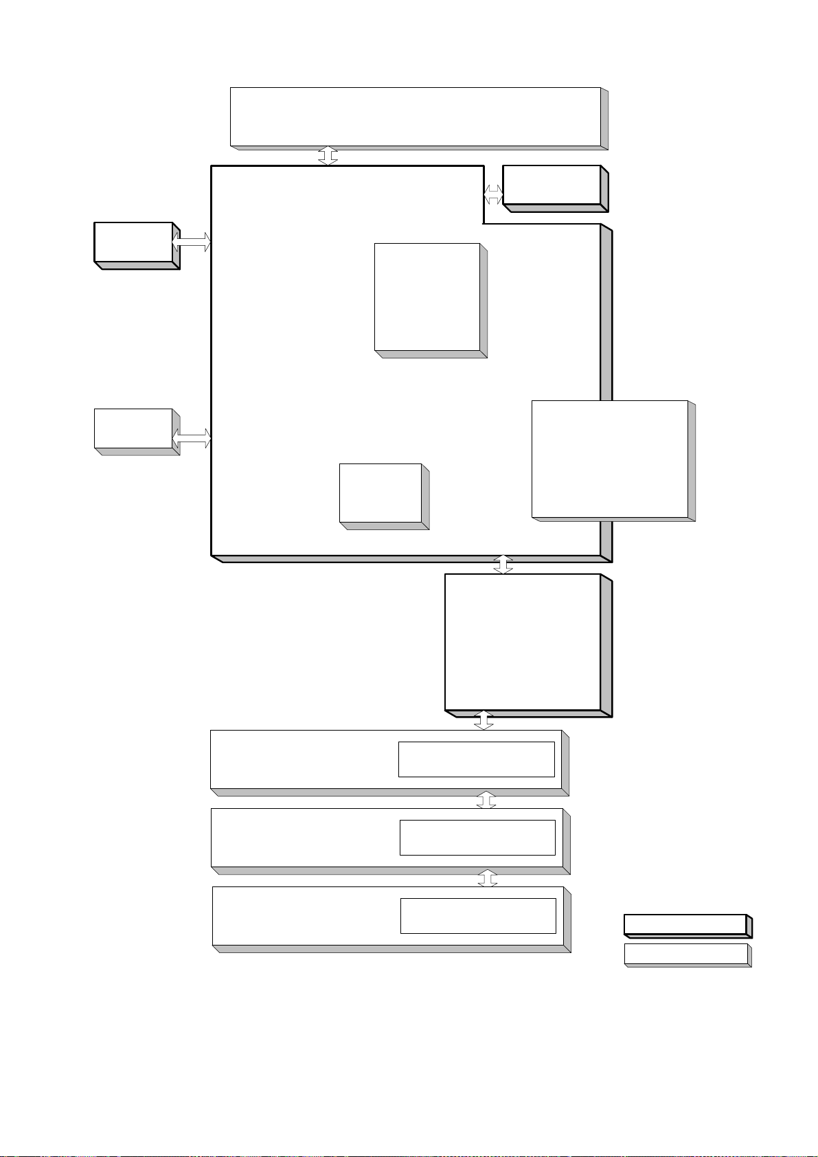
1.3. System Combination
For DP-1510P/1810P
ADF or Platen Cover
ADF PC Board
DP-1510P/1810P
/1810F/2010E
Panel
(PNL PC Board)
Dehumidifier
Heater Kit
Main PC Board
(SC PC Board)
Parallel Port
Interface
Scanner Unit
Image Memory
8, 16, 64,128M
Either Option
Document Sensor
and Motor
PCL6
Emulation Kit
(PDL PC Board)
10/100 Ethernet Interface
Option
2nd Paper Feed Module
Option
LPC3 PC Board
Motor, Driver, Clutch, Sensor
Standard Configuration
Option
Edition 2.0
23
APR 2002
Page 24

For DP-1810F
DP-1510P/1810P
/1810F/2010E
ADF
ADF PC Board
Panel
(PNL PC Board)
Dehumidifier
Heater Kit
Main PC Board
(SC PC Board)
Parallel Port
Interface
Scanner Unit
PCL6
Emulation Kit
(PDL PC Board)
Memory CARD
2, 4, 8M
Either Option
Image Memory
8, 16, 128M
Either Option
Document Sensor
Motor
Fax
(MJR PC Board)
10/100 Ethernet Interface
(Internet Fax)
Handset
Option
Option
2nd Paper Feed Module
Option
3rd Paper Feed Module
Option
4th Paper Feed Module
Option
LPC3 PC Board
Motor, Driver, Clutch, Sensor
Motor, Driver, Clutch, Sensor
Motor, Driver, Clutch, Sensor
Standard Configuration
Option
Edition 2.0
24
APR 2002
Page 25
For DP-2010E
DP-1510P/1810P
/1810F/2010E
i-ADF, ADF or Platen Cover
ADF PC Board
Panel
(PNL PC Board)
Dehumidifier
Heater Kit
Main PC Board
(SC PC Board)
Parallel Port
Interface
Scanner Unit
Image Memory
8, 16, 128M
Either Option
Document Sensor
Motor
PCL6
Emulation Kit
(PDL PC Board)
10/100 Ethernet Interface
Option
2nd Paper Feed Module
Option
(Standard for USA, Canada)
3rd Paper Feed Module
Option
4th Paper Feed Module
Option
LPC3 PC Board
Motor, Driver, Clutch, Sensor
Motor, Driver, Clutch, Sensor
Motor, Driver, Clutch, Sensor
Standard Configuration
Option
Edition 2.0
25
APR 2002
Page 26

DP-1510P/1810P
/1810F/2010E
1.4. Option and Supply Lists
1.4.1. Options
Part Name Part Number Remarks
10/100 Ethernet Interface DA-NE200 Available in Specified Destinat ions
PCL6 Emulation Kit DA-PC210
Image Memory (8MB) DA-SM08B Only one module can be installed.
Image Memory (16MB) DA-SM16B
Image Memory (64MB) DA-SM64B
Image Memory (128MB) DA-SM28B
Handset Kit
Expansion Flash Memory Card, 2MB UE-410046
Expansion Flash Memory Card, 4MB UE-410047
Expansion Flash Memory Card, 8MB UE-410048
Automatic Document Feeder DA-AS180 Standard for DP-1810F
Inverting Automatic Document Feeder
(i-ADF)
2nd/4th Paper Feed Module DA-DS182
3rd Paper Feed Module DA-DS183 Except for DP-1510P/1810P
UE-403167 For U.S.A/Canada
UE-403117 For Other Destinations
Only for DP-1810F
DA-AR201 Only for DP-2010E
1.4.2. Supplies
Part Name Part Number Remarks
Toner Bottle DQ-TU10C
OPC Drum DQ-H045B
Sales Route
Edition 2.0
26
APR 2002
Page 27
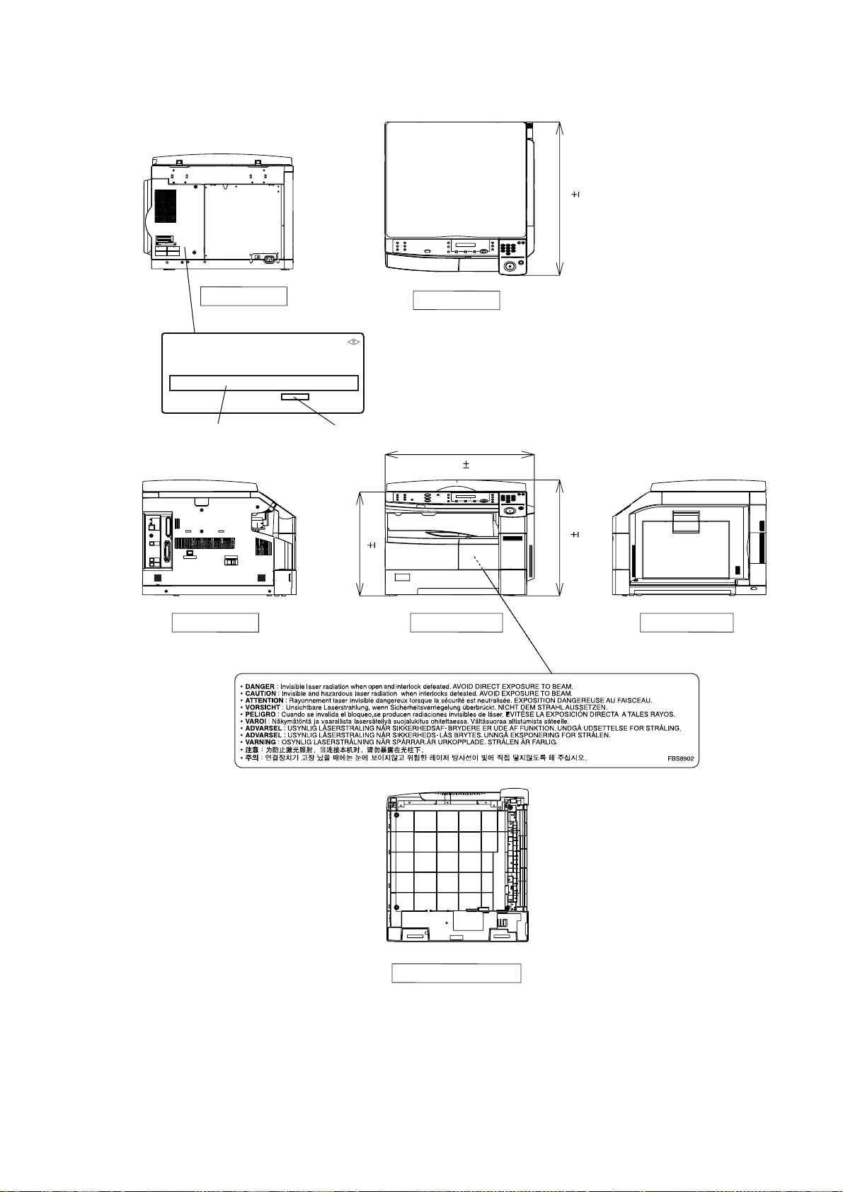
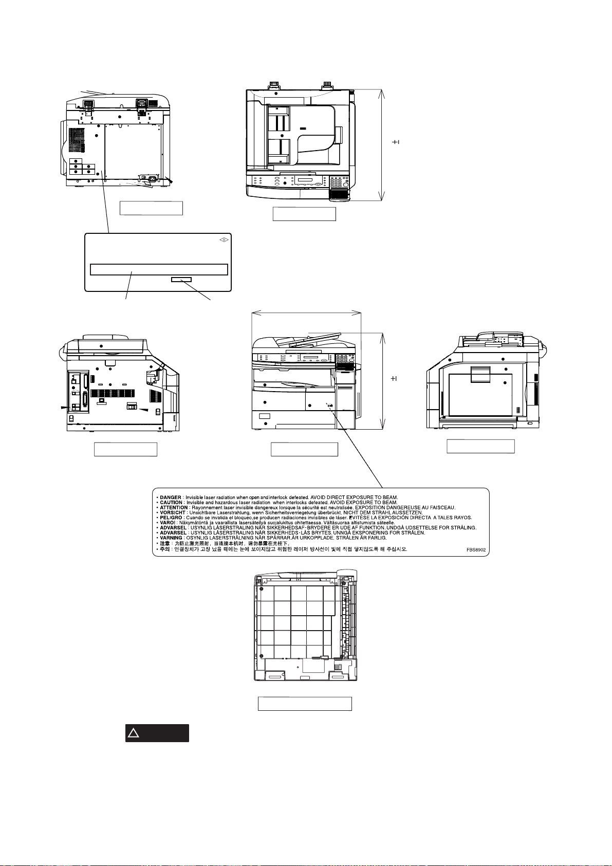
1.5. External View
For DP-1510P/1810P/2010E
FAC8932-00
T
DP-1510P/1810P
/1810F/2010E
10 mm
23.8 in
(605 )
Rear View
(For USA only)
Product complies with DHHS Rules 21
CFR Subchapter J in effect at date
of manufacture.
Manufacturer's name and address
Factory ID
16.1 in
Top View
23.1 in
10 mm
(588 )
10 mm
(410 )
Front View Right ViewLeft View
10 mm
18.0 in
(458 )
Edition 2.0
Bottom View
27
APR 2002
Page 28
For DP-1810F
DP-1510P/1810P
/1810F/2010E
10 mm
23.8 in
(605 )
Rear View
(For USA only)
Product complies with DHHS Rules 21
CFR Subchapter J in effect at date
of manufacture.
Manufacturer's name and address
Factory ID
Top View
23.1 in
10 mm
(588 )
Front ViewLeft View
10 mm
20.6 in
(522 )
Right View
Edition 2.0
Bottom View
CAUTION
!
THIS PRODUCT CONTAINS A LITHIUM BATTERY. DANGER OF EXPLOSION IF BATTERY IS
INCORRECTLY REPLACED.
REPLACE ONLY WITH THE SAME OR EQUIVALENT TYPE. DISPOSE OF USED BATTERIES ACCORDING
TO THE INSTRUCTIONS OF YOUR LOCAL SOLID WASTE OFFICIALS.
28
APR 2002
Page 29

1.5.1. Serial Number Contents
The contents of the 11-digit Serial Number is as follows:
DP-1510P/1810P
/1810F/2010E
2 3 4 5 61
7 8 9 10 11
Sequential Production Number
5-Digit Sequential Production Number
00001 ~ 99999 = 1 ~ 99,999 units
A0001 ~ Y9999 = 100,000 ~ 329,976 units
(Letters “I” and “O” are skipped)
Model Number and Destination Code (Main Unit)
3-Digit number or alphanumeric representation
(Except Letters “I” and “O”)
For Example:
2PS=DP-1510P-PB
2JP=DP-1810P-PU
2HH=DP-1810F-PU
2KG=DP-2010E-PU
Production Facility
Production Year
Starting with Year 2001, the last 2-digits of the year is
represented as: A ~ T
A : 01 (2001) K : 11 (2011)
B : 02 L : 12
C : 03 M : 13
D:04 N:14
E : 05 O : 15
F : 06 P : 16
G:07 Q:17
H:08 R: 18
I : 09 S : 19
J : 10 (2010) T : 20 (2020)
Production Month
A : January G : July
B : February H : August
C : March I : September
D : April J : October
E : May K : November
F : June L : December
Edition 2.0
29
APR 2002
Page 30
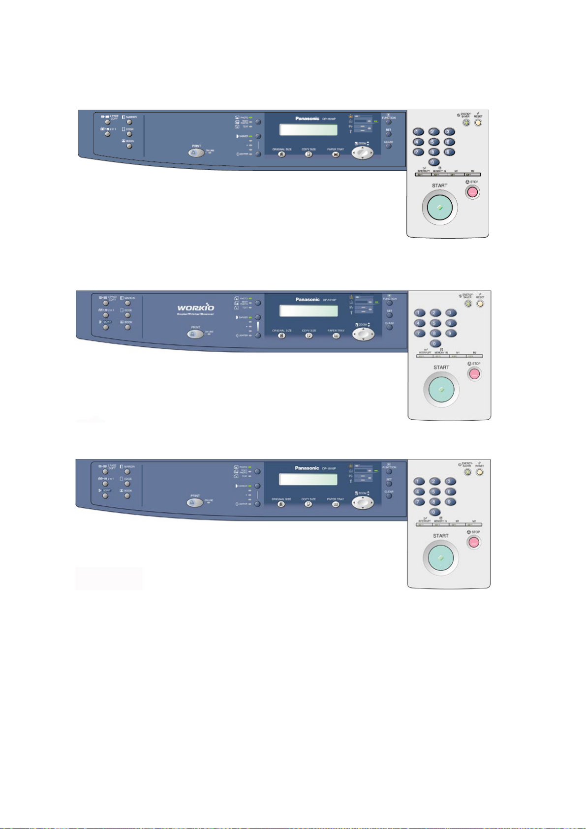
1.6. Control Panel
DP-1510P
For EURO and Other Destinations
DP-1810P
For USA and Canada
DP-1510P/1810P
/1810F/2010E
For Other Destinations
Edition 2.0
30
APR 2002
Page 31

DP-1810F
For All Destinations
DP-2010E
For USA and Canada
DP-1510P/1810P
/1810F/2010E
For Other Destinations
Edition 2.0
31
APR 2002
Page 32

2 Disassembly Instructions
2.1. General Disassembly Flowchart
DP-1510P/1810P
/1810F/2010E
AC Power Cord (1502)
ADF Unit
Separation Rubber (428)
Paper Feed Roller (679) Pre Feed Roller (420)
ADF PC Board (1406)
Feed Roller (409)
SNS PC Board (134)
Cover Assembly
2-2-1
2-2-2
ADF Motor (437)
2-2-3
Front Cover (101) Inner J Cover (103)
Left Side Cover (104)
Rear Plate (801)
Rear Cover (107)
Lift Motor Assembly (1238)
Right Cover Assembly
Duplex Feed Roller (609)
LSU (710)
Micro Switch (813)
SC PC Board (1401)
Drive Motor (1105)
Fan (808)
LVPS (1404)
HTC PC Board (1407)
2-2-15
2-2-17
2-2-6
Fly Wheel (1101)
Fan (1149)
LPC3 PC Board (1402)
HVPS (1403)
Solenoid (1102)
2-2-7
2-2-9
2-2-8
AC Inlet (807)
2-2-10
Edition 2.0
Drive Unit
32
APR 2002
Page 33

DP-1510P/1810P
/1810F/2010E
Control Panel Unit
LCD Cover (201)Speaker (125)
PNL6 PC Board (1416)
Panel Cover (202)
PNL2 PC Board (1417)
Scanner Unit
Left Platen Cover (113) Right Platen Cover (112)
Glass L Assembly (117) Glass S (116)
Scanner Lamp (501)
Inverter PC Board (564) FPC Cable (547)
Scanning Motor (131)
Fuser Unit
Fuser Lamp (924)
Pressure Roller (914)
Exit Lower Guide (902)
Separator (923)
2-2-4
2-2-5
2-2-11
Harness Guide (906)
Thermistor Assembly (944) Thermostat (947) Thermal Fuse (948)
Heat Roller (913)
Exit Roller (912)
Registration Roller (1162)
2-2-12
Process Unit Guide (1142)
Toner Sensor (1147)
Separation Pad (659)
Paper Feed Roller (679) Bias Transfer Roller (648)
Roller Cleaner (640)
2-2-13
Edition 2.0
33
APR 2002
Page 34

Feed Roller (1213)
DP-1510P/1810P
/1810F/2010E
2-2-14
Reverse Clutch (1212)
C25 Gear Roller (1207)
Process Unit
Toner Waste Container
OPC Drum (1001)
Bias Charge Roller (1036)
Scoop Sheet (1033)
Cleaning Blade Assembly (1035)
Front & Rear Cleaning Felt (1031, 1032)
Cleaning Sponge (1030)
2-2-16
Mag Roller Joint (1047)
Mag Roller (1048)
Gap Roller (1049)
Dr. Blade Assembly (1040)
Development Felt (1041)
Edition 2.0
34
APR 2002
Page 35

2.2. Disassembly Instructions
2.2.1. Power Cord, Recording Paper Tray, Process Unit
(1) Turn the Power Switch to the OFF (O) position.
(2) Disconnect the AC Power Cord (1502).
(1)
(2)
(3) Remove the Paper Tray.
DP-1510P/1810P
/1810F/2010E
(7)
(6)
(3)
(4)
(5)
(4) Open the Right Cover (601).
(5) Open the Front Door Cover (102).
(6) Remove the Toner Waste Container by slowl y
pulling it towards the left as illustrated.
(7) Seal the Container with the enclosed cap and
dispose of it properly.
(8) Lift the Release Latch (White) and remove the
Process Unit.
Edition 2.0
(8)
35
APR 2002
Page 36

2.2.2. ADF Unit
(3)
(2)
(1)
(4)
(4)
(5)
(6)
(8)
(10)
(7)
(10)
(8)
(9)
DP-1510P/1810P
/1810F/2010E
(1) Open the ADF Cover (418) and release the ADF
Cover Stopper (414).
(2) Remove the Pad Cover (427).
(3) Remove the Separation Rubber (428).
(4) 2 Screws (19).
(5) Remove the ADF Cover (418).
(6) Disconnect the ADF Harness (1836).
(7) Remove the Pick Up Spring (426).
(8) Remove 2 Snap Rings (G3).
(9) Remove the Clutch (1141).
(10) Remove 2 Bushings (410).
Edition 2.0
36
APR 2002
Page 37

DP-1510P/1810P
/1810F/2010E
(12)
(A)
(B)
(11)
(11) Remove Roller Holder (430) Assembly.
(12) Remove the Paper Feed Shaft Assembly
(433).
Note:
When re-installing, make sure that the Roller
Holder (430) Assembly is properly placed on the
ADF Unit.
(13)
(14)
(14)
(16)
(15)
(13) Remove Paper Feed Roller (679) and D26 D
Gear (429).
(14) Remove the Pre Feed Roller (420), Pre Feed
Shaft (421) and Pre Feed Gear 1 and 2 (422,
423).
(15) 2 Silver Screws (B1).
(16) Lift cover and release the Latch Hook then
remove the ADF Rear Cover (301).
Edition 2.0
37
APR 2002
Page 38

DP-1510P/1810P
(17)
(18)
(19)
(20)
(21)
(22)
(23)
(24)
(25)
/1810F/2010E
Note:
When re-installing the ADF Rear Cover (301),
make sure that the ADF Harness is properly
placed as shown in the illustration.
(17) 1 Screw (19).
(18) Remove the ADF PC Board Cover (453).
(19) Release the Clamp from ADF Unit.
Note:
Do not cut the Tie-Wrap. Push the release clip on
the side of the clamp to remove it.
(20) Disconnect the Harness (1806) on the ADF PC
Board (CN21).
(21) 2 Silver Screws (B1).
(22) Remove 2 Angle Plate (305).
(23) Open the ADF Unit.
(24) 4 Screws (6A).
Caution:
Don’t close the ADF Unit subsequent to this step.
(25) Remove the ADF Unit.
Edition 2.0
38
APR 2002
Page 39

(28)
(26)
(26)
DP-1510P/1810P
/1810F/2010E
(26) Disconnect 5 Harnesses (1836, 1837, 1838,
1839, 1840) on the ADF PC Board. (6
connectors)
(27) 2 Screws (19).
(28) Remove the ADF PC Board (1406).
(27)
(31)
7
(31)
6
4
(29)
3
(29)
(31)
(32)
(31)
(29) Release the Harness from the Clamp.
(30) Disconnect 2 H arnesses (1836, 1838).
(31) 7 Screws (19).
(32) Remove the Motor Bracket (439) Assembly.
(30)
5
1
2
Note:
When re-assembling the Motor Bracket (439)
Assembly, follow the steps as illustrated.
Edition 2.0
(33)
(33) 2 Screws (18).
(34) Remove the ADF Motor (437).
(34)
39
APR 2002
Page 40

DP-1510P/1810P
(35)
(36)
(37)
(41)
(40)
(39)
(38)
(43)
(44)
(42)
(46)
(45)
(45)
(45)
(47)
(50)
(48)
(50)
(51)
(49)
/1810F/2010E
(35) Remove 2 Drive Belts (444, 445).
(36) Remove the S27 Pulley (443).
(37) Remove the Bushing (410).
(38) Remove the Snap Ring (B9).
(39) Remove the S27 Pulley (443).
(40) Remove the Bushing (410).
(41) Release the clips and remove the Switch (724).
Note:
Apply Molykote EM-50L Grease to 3 shafts on
Bracket R (447).
<Turn the ADF upside down>
(42) Remove the edge of the Scanning Pad (338).
(43) 1 Screw (19).
(44) Remove the Exit Roller (316) and P6L8
Bushing (317).
(45) 8 Screw (1N).
(46) Remove the Hinge Units L and R.
(47) Release 2 Latch Hooks.
<Return the ADF to its upright position>
(48) Remove the ADF Front Cover (302).
(49) Release the Harnesses (1837, 1839) from the
Clamp.
(50) 5 Screws (19).
(51) Remove the Original Tray.
Edition 2.0
40
APR 2002
Page 41

DP-1510P/1810P
/1810F/2010E
(56)
(57)
(54)
(60)
(61)
(55)
(53)
(58)
(52)
(62)
(52) 5 Screws (19).
(53) Remove the Center Bracket (452).
(54) Release the NP Actuator Spring (408).
(55) Remove the NP Actuator (407).
(56) Disconnect the Harness (1837). (2 Connectors)
(57) Remove the Photo Sensor (604).
(58) Remove the Photo Sensor (604).
Note:
Do not break the Latch Hooks when removing or
re-installing the Photo Sensors (604).
(59) Remove the Snap Ring (B9).
(60) Remove 2 Bushing (410).
(61) Remove the Timing Actuator (403).
(62) Remove the Feed Roller (409).
(60)
(59)
(65)
(63)
(63)
(68)
(66)
(67)
(64)
(69)
(63) 4 Silver Screws (B1).
(64) Remove the Original Lower Tray (327).
(65) 1 Screw (62).
(66) Disconnect the Harness (1839) on the SNS PC
Board.
(67) Remove the SNS PC Board (134).
(68) Disconnect 2 H arnesses (1839) on the Photo
Sensors.
(69) Remove 2 Photo Sensors (604).
Edition 2.0
41
APR 2002
Page 42

DP-1510P/1810P
(1)
(2)
(3)
(3)
(3)
(2)
(1)
(2)
(2)
(2)
A
(1)
(2)
/1810F/2010E
<Cleaning the Rollers and Rubber>
(1) Open the ADF Cover.
(2) Release the Stopper.
(3) Clean the Separation Rubber, Feed Roller, Pre
Feed Roller and Paper Feed Roller with a soft
cloth, saturated with isopropyl alcohol.
<Cleaning the Exit Roller>
(1) Lift the Original Tray.
(2) Clean the Exit Roller with a soft cloth, sat urated
with isopropyl alcohol.
<Cleaning the Scanner>
(1) Open the ADF Unit.
(2) Clean the White Guide, Scanning Pad and
Scanning Glasses with a soft cloth, saturated
with isopropyl alcohol.
Note:
Ensure that the Film of the part A is not damaged.
Edition 2.0
42
APR 2002
Page 43

2.2.3. Cover Assembly
(3)
DP-1510P/1810P
/1810F/2010E
(1) 3 Screws (19).
(2) Release the 3 Latch Hooks and Remove the
Front Cover (101).
(3) Remove the Inner J Cover (103).
Latch
Hooks
(4)
(1)
(5)
(2)
(1)
(8)
(4)
(6)
(7)
(4) 4 Silver Screws (B1).
(5) Remove the Left Side Cover (104).
(6) 7 Screws (19).
(7) Remove the Rear Plate (801).
(8) 2 Silver Screws (B1).
(9) Remove the Rear Cover (107).
(11)
(10)
(9)
(8)
(10) 1 Screw (19).
(11) Remove the Harness Cover (158).
(12) Release the Harness (1845) from the Clamps.
(13) Disconnect the Connector.
(12)
(13)
Edition 2.0
43
APR 2002
Page 44

DP-1510P/1810P
(14)
(15)
(16)
(A)
/1810F/2010E
(14) Remove the Right Cover St opper (625).
(15) Remove the Front Arm (657).
(16) Remove the Right Cover (601) Assembly.
Note:
Remove the front fulcrum (A) and then pushing the
Right Cover (601) Assembly toward the rear,
remove the rear fulcrum.
Edition 2.0
44
APR 2002
Page 45

2.2.4. Control Panel Unit
DP-1510P/1810P
/1810F/2010E
(4)
(6)
(1)
Latch Hooks
(3)
(5)
(7)
(1) 2 Silver Screws (B1).
(2) 2 Screws (19).
(3) Release 2 Latch Hooks and remove the
Control Panel Assembly.
(4) Disconnect the Harness (1801) on the PNL6 PC
Board (CN201).
(2)
<Following steps (5)~(11) is for DP-1810F only>
(5) Disconnect the Harness.
(6) 1 Screw (19).
(7) Remove the Speaker (125) Assembly.
(11)
(10)
(8)
(9)
(8) 2 Screws (C2).
(9) 1 Screw (19).
(10) Remove the Speaker (125).
(11) Remove the Battery Holder (247).
Note:
When re-installing, you need setting time.
Edition 2.0
45
APR 2002
Page 46

DP-1510P/1810P
(12)
(14)
(13)
(15)
(16)
(17)
(17)
(17)
(17)
(18)
(20)
(19)
(19)
(19)
(19)
/1810F/2010E
(12) 1 Screw (19).
(13) Remove the Panel Bracket (233).
(14) Disconnect the Harness (1852) on t he PNL6 PC
Board (CN1).
Note:
During re-assembly, reconnect this Harness to
PNL6 PC Board prior to securing the board with
the screws.
(15) 2 Screws (7B).
(16) Release 2 Latch Hooks and remove the LCD
Cover (201) and Panel Cover (202).
(17) 10 Screws (7B).
(18) Remove the PNL2 PC Board (1417).
(19) 14 Screws (7B).
(20) Remove the PNL6 PC Board (1416).
Edition 2.0
46
APR 2002
Page 47

2.2.5. Scanner Unit
DP-1510P/1810P
/1810F/2010E
(10)
(1)
(8)
(2)
(5)
(4)
(3)
(6)
(7)
(9)
(1) 2 Silver Screws (B1).
(2) Remove 2 Angle Plates (305).
(3) Open the ADF Unit.
(4) 3 Silver Screws (B1).
(5) Remove the Left Platen Cover (113).
(6) 3 Silver Screws (B1).
(7) Remove the Right Platen Cover (112).
(8) 2 Screws (19).
(9) Remove the Glass L Assembly (117).
(10) Remove the Glass S (116).
(2)
<Cleaning the Mirror>
(1) Move the Mirror Unit.
(1)
(2) Clean the Mirror 1 (551) and Mirror 2 (552) with
a soft cloth, saturated with isopropyl alcohol.
Edition 2.0
47
APR 2002
Page 48

DP-1510P/1810P
(12)
(13)
(12)
(15)
(16)
(16)
(14)
(17)
(18)
(20)
(19)
(21)
/1810F/2010E
(11) R emove the Control Panel Uni t
(Refer to 2.2.4.).
(12) 5 Screws (19).
(13) Remove the F/R Scanner Frame (532).
(14) Move the Lamp Base Bracket.
(15) 2 Screws (19).
(16) Remove 2 Lamp Plate Springs (524).
(17) Disconnect Harness on the LFB PC Board.
(18) Remove the Scanner Lamp (501).
(19) Disconnect 2 Harnesses (1805, 1851) on the
Inverter PC Board (CN1 and CN2).
(20) 1 Screw (19).
(21) Remove the Inverter Upper Cover (508).
Edition 2.0
48
APR 2002
Page 49

DP-1510P/1810P
/1810F/2010E
(24)
(25)
(22)
(22) 2 Screws (19).
(23) Remove the Inverter PC Board (564).
(23)
(22)
(24) 2 Screws (19).
(25) Remove LFB PC Board (1414) Assembly and
LFB PC Board (1414).
(26) Disconnect the Harness on the LFB PC Board.
(25)
(26)
(28)
(30)
(27) Remove 2 Sliders on the Connectors.
(28) Remove the FPC Cable (260).
Note:
The Sliders must be re-installed when
reassembling.
(27)
(29) Remove the ADF Unit. (Refer to 2.2.2.)
(30) 2 Silver Screws (B1).
(31) Remove the Rear Platen Cover (114).
(31)
Edition 2.0
49
APR 2002
Page 50

DP-1510P/1810P
(33)
(34)
(35)
(38)
(36)
(37)
(39)
(40)
(41)
/1810F/2010E
(32) Remove the Rear Cover and Rear Plate.
(Refer to 2.2.3.)
(33) Remove the E-Ring (5Y).
(34) Remove the Synchronous Belt (118).
(35) Remove the MXL34 Pulley (119).
(36) 3 Screws (19).
(37) Disconnect the Harness (1807) on the Scanning
Motor.
(38) Remove the Scanning Motor Bracket (1 20)
Assembly.
Note:
When re-installing the Motor Bracket, tighten the
upper screw first.
(39) 2 Screws (36).
(40) Remove the Scanning Motor (131).
(41) Disconnect the Harness (1831) on the SC PC
Board (CN106 and CN120).
Edition 2.0
50
APR 2002
Page 51

DP-1510P/1810P
/1810F/2010E
(48)
(47)
(43)
(49)
(42)
(45)
(44)
(46)
(42) Release the Harnesses from the Clamps.
(43) Disconnect the Harness (1805).
(44) Disconnect the Harness (1803).
(45) 1 Screw (19).
(46) Remove the Front Platen Frame Bracket (127).
(47) 1 Screw (19).
(48) Remove the Rear Platen Frame Bracket (128).
(49) 1 Screw (19).
(50)
(50) Remove the Scanner Unit.
Edition 2.0
51
APR 2002
Page 52

2.2.6. LSU, Fan, LVPS, HTC PC Board
(1)
(3)
(2)
(A)
(4)
(5)
(4)
(6)
(7)
(8)
(7)
DP-1510P/1810P
/1810F/2010E
(1) 2 Screws (19).
(2) Disconnect 2 Harnesses (1809, 1824).
(3 connectors)
(3) Remove the LSU (710).
Note:
Do not touch the RED Screw (A) of LSU Damper
as illustrated.
Note:
When re-installing the L SU, put the latch und er the
Plate Spring.
(4) 5 Screws (19).
(5) Remove the LVPS Plate (804) Assembly.
Note:
When re-installing the LVPS Plate (804)
Assembly, make sure that the latch is not over the
Power SW.
(6) 1 Screw (E5).
(7) 3 Screws (19).
(8) Remove the Upper Fan Bracket (806).
Edition 2.0
52
APR 2002
Page 53

(10)
DP-1510P/1810P
/1810F/2010E
(9) 1 Screw (E5).
(10) Disconnect the Harness (1814).
(11) Remove the Fan (808).
(12)
(9)
(11)
(14)
(13)
(12)
(16)
(12) 3 Screws (19).
(13) Remove the Lower Fan Bracket (805).
(14) Disconnect the Harness (1830) on the LVPS
(CN60).
(15) Disconnect 2 H arnesses (1812, 1822) on the
LVPS (CN61 and CN62).
(16) Remove the Inner FL Cover (110).
(15)
(17)
(17)
(18)
(17)
(17) 5 Screws (19).
(18) Remove the LVPS Assembly.
Edition 2.0
53
APR 2002
Page 54

DP-1510P/1810P
(19)
(19)
(20)
(21)
(21)
(21)
(23)
(24)
(23)
(25)
(21)
(22)
(21)
/1810F/2010E
(19) 6 Screws (19).
(20) Remove the LVPS (1404).
Note:
When re-installing the LVPS, install the upper 4
Screws first and then the remaining 2 Screws.
(21) Disconnect all Harnesses on t he HTC PC Board
(CN760, CN761, CN762, CN764, CN765,
CN766 and CN767).
(22) Remove the Clamp (730).
(23) Release the Locking Support C (728).
(24) 1 Screw (19).
(25) Remove the HTC PC Board (1407).
Edition 2.0
54
APR 2002
Page 55

2.2.7. ILS, Fan
DP-1510P/1810P
/1810F/2010E
(1) 2 Screws (E6).
(2) Remove 2 Micro Switch (813) and Disconnect 2
Harnesses (1823).
(7)
(2)
(3)
(6)
(4)
(1)
(3) 1 Screw (24).
(4) Remove the 3 Fly Wheels (1101).
Note:
When re-installing the Fly Wheels, make sure
that the Imprinted Marks are facing outward.
(5) 2 Screws (E5).
(6) Disconnect the Harness (1820).
(7) Remove the Fan (1149).
(5)
Edition 2.0
55
APR 2002
Page 56

2.2.8. SC PC Board, LPC3 PC Board, MJR PC Board (For DP-1810F Only)
(2)
(2)
(1)
(1)
(3)
(4)
(5)
(7)
(7)
(8)
(6)
(7)
(1) Disconnect 2 Harnesses (1866, 1867)
(2) 2 Screws (19).
(3) Remove the MJR PC Board (1421).
(4) Remove the Locking Spacer (824).
DP-1510P/1810P
/1810F/2010E
(5) Disconnect all Harnesses on the SC PC Board
(1401).
(6) 2 Screws (20).
(7) 7 Screws (19).
(8) Remove the SC PC Board (1401).
Edition 2.0
56
APR 2002
Page 57

(10)
(11)
(11)
(12)
(9)
(13)
DP-1510P/1810P
/1810F/2010E
Note:
When re-installing the SC PC Board.
(9) Release 2 Latch Hooks and remove the Card
Guide (816).
(10) Move 2 Lock Springs as illustrated.
(11) 2 Screws (20).
(12) Reinstall the Card Guide (816) as illustrated.
(13) Position the Memory Ground Plate (721) as
illustrated.
Note:
Make sure that the leg of the Memory Ground
Plate is properly install ed into the hole of the Card
Guide as illustrated in (A).
(16)
(17)
(A)
(14)
(14) 1 Screw (19).
(15) 7 Screws (19).
(16) Disconnect all Harnesses on the LPC3 PC
Board.
(17) Release the Support and remove the LPC3 PC
Board (1402).
Edition 2.0
57
APR 2002
Page 58

2.2.9. Drive Motor, HVPS, Solenoid, Drive Unit
(3)
(4)
(2)
(1)
(3)
(4)
(5)
(6)
(7)
(9)
(10)
(11)
(11)
(8)
(10)
(9)
Purple
Orange
<Drive Motor>
(1) Release the Harness (1818) from the Clamp.
(2) Disconnect the Harness (1818) on the Drive
(3) 4 Screws (19).
(4) Remove the Drive Motor.
<HVPS, Solenoid and Drive Unit>
(1) Remove 3 Fly Wheels. (Refer to 2.2.7.)
(2) Remove the Harness from the Clamps.
(3) 4 Screws (19).
(4) Remove the HVPS Assembly.
(5) Disconnect the Harness (1825) on the HVPS
DP-1510P/1810P
/1810F/2010E
Motor Assem b ly.
(Refer to 2.2.3.)
(CN800).
(6) 2 Screws (19).
(7) Remove the HVPS (1403).
(8) Release the Harness (1826) from the Clamp.
(9) Remove 2 Snap Rings (B9).
(10) Remove 2 Clutches (1141, 1224).
(11) D isconnect the Harnesses (1826).
(2 connectors)
Edition 2.0
58
APR 2002
Page 59

(12)
(14)
DP-1510P/1810P
/1810F/2010E
(12) 2 Screws (19).
(13) Remove the CST Cover (716) Assembly.
(13)
(14) Release the Solenoid Harness from 2 Clamps.
(17)
(15) Remove the Rear Plate. (Refer to 2.2.3.)
(16) Release the Solenoid Harness from Clamp and
Disconnect it.
(16)
(17) 2 Screws (19).
(18) Remove the Paper Feed Roller Assembly.
(18)
Edition 2.0
59
APR 2002
Page 60

(19) 2 Screws (19).
(19)
(20)
(21)
(22)
(23)
(24)
(25)
(26)
(20) Remove the Solenoid Assembly.
(21) 1 Screw (19).
(22) Remove the Solenoid (1102).
DP-1510P/1810P
/1810F/2010E
(23) 2 Screws (19).
(24) Remove the Fan Assembly.
(25) Push down the Latch Hook with a Straight Edge
Screwdriver.
(26) Remove the Fuser Actuator 2 (1116).
Edition 2.0
60
APR 2002
Page 61

(28)
(29)
(31)
(30)
(30)
DP-1510P/1810P
/1810F/2010E
(27) Disconnect the Harnesses (1229, 1856) on the
LPC3 PC Board.
(28) Release the Harness (1818) from the Clamp.
(29) Disconnect the Harness (1818) on the Drive
Motor Assembly.
(30) 4 Screws (19).
(31) Remove the Drive Unit.
Caution:
Do not remove the Gears from the Drive Unit.
If dis-assembled or the Alignment i s necessary, be
careful to assemble the Gears by following steps.
<Toner Bottle Drive Gear Adjustment>
2 Holes
(1)
Sensor
(2)
(1) Remove 2 Snap Rings and 2 Gears as
illustrated.
(2) Align 2 Gear Holes with the Sensor.
(3) Align the Joint Gear to the Vertical Position as
illustrated.
Edition 2.0
(3)
61
APR 2002
Page 62

DP-1510P/1810P
(5)
(4)
/1810F/2010E
(4) Install the Gear and the Snap Ring.
(5) Install the other Gear and Snap Ring.
Edition 2.0
62
APR 2002
Page 63

2.2.10. AC Inlet
(2)
(5)
(1)
(3)
(7)
(4)
(4)
DP-1510P/1810P
/1810F/2010E
(1) 1 Silver Screw (B1).
(2) Remove the In let Cover (751).
(3) 2 Screws (35).
(4) Disconnect 2 H arnesses (1828).
(5) Remove the A C In le t Assembly.
(6) Disconnect the Harness (1842).
(7) Remove the A C In le t (807).
(6)
Edition 2.0
63
APR 2002
Page 64

2.2.11. Fuser Unit
(2)
(2)
(3)
(1)
(4)
(5)
(6)
(7)
(9)
(8)
(12)
(13)
(11)
(10)
(A)
(B)
DP-1510P/1810P
/1810F/2010E
(1) Open the Right Cover (601) Assembly.
(2) 2 Screws (19).
(3) Remove the Front Connector Cover (714).
(4) Remove the Rear Connector Cover (713).
(5) 2 Screws (4N).
(6) Remove 2 Harnesses (1829).
(7) Remove 2 Harnesses (1813).
(8) Release 2 Harnesses (1829) from the Clamp.
(9) Remove the Fuser Unit.
(10) 1 Screw (23).
(11) 1 Screw (19).
(12) Remove the Lamp Holder (925).
(13) 1 Screw (23). (Opposite side)
Note:
When re-installing the Lamp Holder (92 5), insert
the Lamp Holder’s Leg (A) into the Guide (B).
Edition 2.0
64
APR 2002
Page 65

(14)
DP-1510P/1810P
/1810F/2010E
(14) Remove the Fuser Lamp (924).
Note:
Do not Touch the glass portion of the Fuser Lamp
with bare hands. Grease from finger prints will
shorten its life cycle, use isopr opyl alcohol to clea n
finger prints.
(15) Remove the Snap Ring (B9).
(16) Remove the Jam Release Knob (934).
(16)
(15)
(17) 1 Screw (19).
(18) Remove the Right Side Cover (904).
(17)
(18)
(19) Release the Jam Release Guide Spring (926).
(20) Remove the Jam Release Guide (903).
Edition 2.0
(20)
(19)
65
APR 2002
Page 66

/1810F/2010E
(21)
(21)
(22)
(23)
(23)
(24)
(25)
(21) 2 Screws (G5).
(22) Remove the Exit Upper Guide (901).
(23) Remove 2 Pressure Springs (952).
DP-1510P/1810P
(24) Remove the Pressure Roller (914).
(25) Remove the Exit Lower Guide (902).
Edition 2.0
66
APR 2002
Page 67

(27)
(26)
(1)
DP-1510P/1810P
/1810F/2010E
<Cleaning Separator>
(2)
(1) Clean the Separators with a soft cloth, satur ated
with isopropyl alcohol.
(2) Clean 2 Separation HR Sheets with a soft cloth,
saturated with isopropyl alcohol .
(26) Remove 3 Separator Springs (953).
(27) Remove 5 Separators (923).
(29)
(28) Remove the Exit Lever (921).
(28)
(29) Remove 2 Separation HR Sheets (970).
Edition 2.0
67
APR 2002
Page 68

DP-1510P/1810P
(31)
(33)
(30)
(32)
(1)
(2)
(35)
(37)
(39)
(34)
(36)
(38)
(1)
/1810F/2010E
(30) 1 Screw (23).
(31) 1 Screw (19).
(32) Release the Stopper and disconnect the
Harness.
(33) Remove the Harness Guide (906 ).
<Cleaning Thermistor Assembly, Thermostat>
(1) Clean the Thermistor Assembly (944) with a
soft cloth, saturated with isopropyl alcohol.
(2) Clean the Thermostat (947) with a soft cloth,
saturated with isopropyl alcohol.
(34) 2 Screws (23).
(35) Remove the Thermal Fuse (948 ).
(36) 2 Screws (23).
(37) Remove the Thermostat (947).
(38) 1 Screw (1Y).
(39) Remove the Thermistor Assembly (944).
<Cleaning the Fuser Roller>
(1) Clean the Fuser Roller (913) with a soft cloth,
saturated with isopropyl alcohol.
Edition 2.0
68
APR 2002
Page 69

DP-1510P/1810P
/1810F/2010E
(40)
(41)
(40)
(40) 5 Screws (19).
(41) Remove the Roller Bracket (909).
Note:
When re-installing, install the Screw A first, then
the remaining 4 Screws.
A
(40)
(42) Remove the Fuser Roller (913).
(42)
(46)
(45)
(43)
(48)
(49)
(45)
(44)
(43)
(48)
(47)
(46)
(43) Remove 2 C-Rings (938).
(44) Remove the E39 D Gear (935).
(45) Remove 2 P30L6.8 Bushings (937).
(46) Remove 2 Snap Rings (B9).
(47) Remove the E24 D Gear (936).
(48) Remove 2 P6L5 Conductor Bushings (939).
(49) Remove the Exit Roller (912).
Edition 2.0
69
APR 2002
Page 70

2.2.12. Registration Roller, Toner Sensor
(4)
(5)
(6)
(7)
(6)
(10)
(9)
(11)
(12)
(13)
DP-1510P/1810P
/1810F/2010E
(1) Remove the Rear Cover. (Refer to 2.2.3.)
(2) Remove 3 Fly Wheels. (Refer to 2.2.7.)
(3) Remove the HVPS, Snap Ring and Clutch.
(Refer to 2.2.9.) (4) Remove the Snap Ring (B9). (5) Remove the Registration Roller (1162).
(6) Remove 2 Bushings (939, 1144).
(7) Remove the D17 D Gear (1143).
(8) Remove the Front Cover and Right Cover
Assembly. (Refer to 2.2.3.)
(9) 1 Screw (19).
(10) Remove the Process Unit Guide (1142).
(11) R emove the Registration Actuator (1146).
(12) Remove the Photo Sensor (604).
(13) Remove the Harness (1827).
Edition 2.0
70
APR 2002
Page 71

(17)
(15)
(16)
(14)
DP-1510P/1810P
/1810F/2010E
(14) 1 Screw (19).
(15) Disconnect the Harness (1827).
(16) Remove the Toner Sensor Spring (1148).
(17) Remove the Toner Sensor (1147).
(19)
(18)
(19)
(18)
(18) Disconnect the Harness (1827).
(19) Remove 2 Photo Sensors (604).
Edition 2.0
71
APR 2002
Page 72

2.2.13. Bias Transfer Roller
(2)
(1)
(4)
(7)
(6)
(5)
DP-1510P/1810P
/1810F/2010E
<Cleaning the Registration Roller, Duplex
Transf er Roller and Pinch Roller>
(1) Clean the Registration Roller, Duplex Transfer
Roller and Pinch Roller with soft cloth,
saturated with isopropyl alcohol.
(2) Clean the Bias Transfer Roller with soft dry
Cloth.
(3) Remove the Paper Feed Roller Assembly.
(Refer to2.2.9.)
(4) Remove the Separation Pad (659).
<Turning over the Separation Pad>
To improve separation, turn over the Sep aration Pad.
<Cleaning the Paper Feed Roller>
Clean the Paper Feed Roller with soft cloth,
saturated with isopropyl alcohol.
(5) Release the Latch Hook with a small
screwdriver.
(6) Remove the Feed Roller Shaft (677).
(7) Remove the Paper Feed Roller (679).
Edition 2.0
72
APR 2002
Page 73

(8)
(9)
DP-1510P/1810P
/1810F/2010E
(8) 2 Screws (C8).
(9) Remove the BTR Guide (642).
(10) Release 2 Latch Hooks and remove the BTR
Gear (644).
(10)
(11)
(12)
(11) Remove the Bias Transfer Roller (648).
Note:
When re-installing t he Bias T rans fer Roller (648),
make sure that the Springs are on both sides, the
White Bushing is in front and the Black Bushing
is in rear.
(12) 1 Screw (C8).
(13) Remove the Timing Pinch Roller (647).
(13)
Edition 2.0
73
APR 2002
Page 74

(14) Remove the Cleaner Roller (640).
(14)
DP-1510P/1810P
/1810F/2010E
Edition 2.0
74
APR 2002
Page 75

2.2.14. Paper Feed Module
(1)
(2)
(3)
DP-1510P/1810P
/1810F/2010E
<Cleaning the Paper Feed Roller and C25 Gear
Roller>
Clean the Paper Feed Roller and C25 Gear Roller
with soft cloth, saturated with isopropyl alcohol.
(1) Release the Latch hook and remove the C25
Gear Roller (1207) and Reverse Clutch (1212).
(2) Remove the Feed Roller (1213).
(3) Remove the C25 Gear Roller (1207) and
Reverse Clutch (1212).
Note:
2nd/3rd/4th Paper Feed Modules are as the same
steps (1)~(3).
(A)
Note:
When re-installing the C25 Gear Roller (1207)
removed in step (3), insert the edge of Clutch
Spring into the groove of Roller.
<Cleaning the Intermediate Roller of 2nd/3rd/4t h
Paper Feed Module>
(1) Open the Jam Cover (1626).
(1)
Edition 2.0
75
APR 2002
Page 76

DP-1510P/1810P
(2)
/1810F/2010E
(2) Clean the Intermedia te R o ller (1617).
Note:
3rd/4th Paper Feed Modules are as the same
steps (1)~(2).
Edition 2.0
76
APR 2002
Page 77

2.2.15. Lift Motor Assembly
(5)
(3)
(4)
DP-1510P/1810P
/1810F/2010E
(1) Remove 3 Fly Wheels. (Refer to 2.2.7.)
(2) Remove the HVPS. (Refer to 2.2.9.)
(3) Disconnect the Harness on the LPC3 PC Board
(CN706).
(4) Release the Harness from the Clamps.
(5) 2 Screws (19).
(6) Remove the Lift Motor Assembly (1238).
(6)
(4)
Edition 2.0
77
APR 2002
Page 78

2.2.16. Process Unit
(3)
(2)
(4)
(1)
(5)
(6)
(7)
DP-1510P/1810P
/1810F/2010E
(1) Open the Right Cover.
(2) Open the Front Door Cover.
(3) Remove the Toner Waste Container by slowly
pulling it towards the left as illustrated.
(4) Seal the Container with the enclosed cap and
dispose of it properly.
(5) Lift the Release Latch (White) and remove the
Process Unit.
(6) Open the bottom Leg as illustrated.
(7) Release 2 OPC Latches (1044, 1045) and turn
the OPC Drum Assembly in the direction of the
arrow.
Edition 2.0
78
APR 2002
Page 79

(9)
(11)
(8)
(10)
DP-1510P/1810P
/1810F/2010E
(8) Unlock the Front OPC Bushing Assembly
(1003, 1023) by turning it clockwise.
(9) Push the OPC Drum forward from the rear end
as illustrated.
(10) Remove the Front OPC Bushing Assembly
(1003, 1023).
(11) Lift the OPC Drum (1001) as illustrated, holdi ng
the right side where the Front OPC Bushing
Assembly was installed.
Note:
Do not touch the surface of the OPC Drum with
bare hands when removing or re-installing it.
Grease from fingerprints will affect copy quality.
When installing a new OPC Drum, clean the Bias
Charge Roller with a soft dry cloth.
(13)
(12) Remove the Bias Charge Roller (1036).
(12)
(13) Remove the Bias Charge Roller Holder
Assembly (1037, 1038, 1039).
Edition 2.0
79
APR 2002
Page 80

DP-1510P/1810P
(A)
(B)
(14)
(15)
(16)
(17)
(17)
/1810F/2010E
Note:
When re-installing the Bias Charge Roller Holder
Assembly, install the Charge Holder (1037) first
as shown in (A) and then the Charge Bushing
(1038) with the Charge Spring (1039) as shown in
(B).
(14) Remove the Scoop Sheet (1033).
(15) 2 Black Screws (B4).
(16) Remove the Cleaning Blade Assembly (1035).
(17) Remove Front Cleaning Felt (1031) , Rear
Cleaning Felt (1032) and 2 Cleaning Sponges
(1030).
Edition 2.0
80
APR 2002
Page 81

(C)
(A)
(D)
(B)
(C)
DP-1510P/1810P
/1810F/2010E
Note:
1. When re-installing, install 2 CL Sponges (1030)
first as shown in (A), then the CL Blade
Assembly (1035) next as shown in (B), then the
Front CL Felt (1031) and Rear CL Felt (1032) as
shown in (C) and lastly attach the Scoop Sheet
(1033) as shown in (D).
2. When re-installing the CL Felts, make sure that
there is no space between the rubber part of the
CL Blade Assembly and the CL Felts as
illustrated.
3. When re-installing the CL Sponges and the
Scoop Sheet, attach them flat aligning wit h the
edge of the Front OPC Bushing Assembly as
illustrated.
(A)
(21)
(18) 1 Black Screw (B4).
(19) Remove the Rear Hopper Cover (1011).
(19)
(18)
(20) 1 Black Screw (B4).
(21) Remove the Rear OPC Latch (1045).
(20)
Edition 2.0
81
APR 2002
Page 82

DP-1510P/1810P
(22)
(23)
(24)
(25)
(26)
(27)
(28)
/1810F/2010E
(22) Remove the Mag Roller Joint (1047).
(23) Remove the Charge Plate D (1059).
(24) Remove the Mag Roller Stopper (1046) by
gently pushing it downwards.
(25) Remove the Mag Roller (1048).
Note:
1.Do not touch the surface of the Mag Roller.
2.When removing or re-installing, place the Mag
Roller on a cloth or paper and handle it wit h care.
(26) Remove the Gap Rollers (1049).
(27) 2 Black Screws (B4).
(28) Remove the Dr. Blade Assembly (1040).
Edition 2.0
82
APR 2002
Page 83

DP-1510P/1810P
/1810F/2010E
(29)
(29) Remove 2 Developer Felts (1041).
Edition 2.0
83
APR 2002
Page 84

2.2.17. Duplex Feed Roller (For DP-2010E Only)
(2)
(1)
(3)
(4)
(3)
(5)
(5)
(5)
(6)
(8)
(7)
(1) 2 Screws (C8).
(2) Remove the Transfer Guide (639) Assembly.
(3) 4 Screws (19).
(4) Remove the Duplex Guide 3 (675).
DP-1510P/1810P
/1810F/2010E
(5) 5 Screws (19).
(6) Remove the Duplex Guide 1 (602) Assembly.
(7) Disconnect the Harness (1844).
(8) Remove the Photo Sensor (604) lifting the
Paper Actuator (606).
Note:
When re-installing, make sure t hat Photo Sensor is
re-installed properly.
Edition 2.0
84
APR 2002
Page 85

DP-1510P/1810P
/1810F/2010E
(9)
(10)
(11)
(13)
(12)
(13)
(9) Remove 2 E15 D Gears (607).
(10) Remove 2 Snap Rings (B9).
(11) Remove 2 Duplex Feed Rollers (609).
(12) Remove 2 Bushings (611) and 2 Washers
(610).
Edition 2.0
85
APR 2002
Page 86

2.3. Screw Identification Template
DP-1510P/1810P
/1810F/2010E
Ref No.
18
19
20
23
24
35
36
62
Part No. Figure Remark
XYN3+L6
XTB3+8J
XTB3+F8
XYN3+F8
XYN4+F8
XYN4+F6
XYN3+F6
XTB3+6J
Screw
Screw
Screw
Screw
Screw
Screw
Screw
Screw
1N
1Y XTB3+10J
4N XSN3+W8PC
XTB4+8J
Screw
Screw
Screw
5Y XUC4 E-Ring
6A XTB3+12J
7B
B1
B4
B9
XTB26+6J
DZPB000007
XTB3+8JK
DZJM000171
Screw
Screw
Silver Screw
Blue Screw
Snap Ring
Edition 2.0
86
APR 2002
Page 87

DP-1510P/1810P
/1810F/2010E
Ref No.
Part No. Figure Remark
C2 DZPB000020
C8 XTW3+8SFC
D24 DZPA000013
E5 XTB3+32J
E6 XTB3+24J
G5 FFPFA0107B
Screw
Screw
Red Screw
Screw
Screw
Shoulder Screw
Edition 2.0
87
APR 2002
Page 88

3 Maintenance, Adjustments and Check Points
3.1. Required Tools
No. Tool No. Tool
1 Soft Cloth 7 Pliers
2 Isopropyl Alcohol 8 Cotton Swab
3 Phillips Screwdriver (#2) 9 Brush
KS-660 - Conductive Grease
4 Stubby Phillips Screwdriver (#2) 10
5 Slotted Blade Screwdriver (3/32 in) 11
6 Tweezer
3.2. Periodic Maintenance Points
1
2 3 4 5 6 7 8 9 10 11
(Available from Shin-Et su Sil icones of Amer ica, I nc.
URL: http://www.shinetsusilicones.com)
Molykote EM-50L Grease
(Available from Dow Corning,
URL: http://www.dowcorning.com)
DP-1510P/1810P
/1810F/2010E
30
29
28
27
26
25
23
12
13
14
15
22
16
17
18
19
24
Edition 2.0
20
21
88
APR 2002
Page 89

3.2.1. Periodic Maintenance Points Part Description
No. Part Name No. Part Name
1 Roller, Feed (409) 16 Roll er, Bias Transfer (648)
2 Roller, Paper Feed (679) 17 Roller, Registration (1162)
3 Roller, Pre Feed (420) 18 Sheet Bypass
4 Roller, Exit (316) 19 Roller, Paper Feed (679)
5 Guides, Ori ginal F and R (332,335) 20 Roller, C25 Gear (1207)
6 Tray, Original Upper (333) 21 Roller, C25 Gear (1207)
7 Glass L Assembly (117) 22 Proces s Unit
8 Lens, Scanning 23 1st Paper Tray
9 CCD Assembly 24 2nd Paper Tray (Optional )
10 Roller, Exit (912) 25 LSU (710)
11 Thermostat (947) 26 Mirror 2 (552)
12 Roller, Fuser (913) 27 Mirror 1 (551)
13 Lamp, Fuser (924) 28 Mirror 2 (552)
14 Roller, Pressure (914) 29 Lamp, Scanner (501)
15 Drum, OPC (1001) 30 Glass S (116)
DP-1510P/1810P
/1810F/2010E
3.2.2. Periodic Maintenance Method
No. Part Description
1 Memory Data Check 1. Print the RAM DATA for reference and pre-caution.
2 Auto Document
Feeder (ADF)
3 Scanner Unit Check &
4 Transmitter Unit Check &
5 Mirrors Check &
6 Inspection Items Check 1. Check the Harnesses.
7 Gears, Rollers Shafts Check &
8 Timing Belts Check &
Important
Action
Check &
Clean
Clean
Clean
Clean
Grease
Clean
Comments
2. After completing the task(s), print and compare the RAM
DATA with the previously printed one.
1. Clean the Rollers and Separation Rubber with Isopropyl
Alcohol when required.
1. Clean the Scanning Glass or White Seal Guide with
Isopropyl Alcohol when required.
1. Remove any foreign obstacles.
2. Clean the Rollers with Isopropyl Alcohol when required.
1. Do not touch the surface of the Mirrors with your hands.
Clean any dirt or fing erprint s wi th a soft cloth, saturat ed with
Isopropyl Alcohol.
2. Check the Connectors.
3. Check the Screws. If required, replace consumable parts.
1. Check and grease the required Gears and Shafts.
1. Check for belt looseness or abrasion.
2. Adjust the Idle P u lle y.
Edition 2.0
89
APR 2002
Page 90

3.3. Periodic Maintenance Check List
For a detailed Periodic Maintenance Check List.
DP-1510P/1810P
/1810F/2010E
Cleaning Replacement/Adjustment
Cycle
Method
Cycle
(Sheet)
Procedure
Ref. Counter
Mechanical Parts
Ref.
No.
(Sheet)
ADF Unit
Exit Roller 316 60K Alcohol - Refer to
White Sheet 318 60K Alcohol -
Sect. 2.2.2.
F7-05 ADF/i-ADF
PM Count
Feed Roller 409 60K Alcohol Pre Feed Roller 420 60K Alcohol 120K
Separation Rubber 428 - - 60K
Paper Feed Roller 679 60K Alcohol 120K
Scanning Pad 338 60K Dry soft cloth - F7-04 Scanner
PM Count
Scanner Unit
Glass S 116 60K - - Refer to
Sect. 2.2.5.
F7-04 Scanner
PM Count
Glass L Assembly 117 60K - Mirror 1 551 60K - Mirror 2 552 60K - -
Paper Feed Module
C25 Gear Roller 1207 60K Alcohol 120K Refer to
Clutch Assembly 1246 - - 120K
Sect. 2.2.14.
F7-12 1st Paper
Tray Count
Paper Feed Roller 1213 60K Alcohol 120K
Registration Roller 1162 60K Alcohol - Refer to
F7-02 Total Count
Sect. 2.2.12.
C25 Gear Roller 1207 60K Alcohol 120K Refer to
Clutch Assembly 1246 - - 120K
Sect. 2.2.14.
Paper Feed Roller 1213 60K Alcohol 120K
F7-13 2nd Paper
Tray Count
F7-14 3rd Paper
Tray Count
F7-15 4th Paper
Intermediate Roller 1617 60K - Cleaner Roller 640 60K Dry soft cloth 240K Refer to
Separation Pad 659 20K Turn over 40K F7-11
Sect. 2.2.13.
Paper Feed Roller 679 60K Alcohol 120K
Tray Count
F7-02 Total Count
Sheet Bypass Count
Bias Transfer Unit
Bias Tran sfer Roller
(BTR)
648 60K Dry soft cloth 120K Refer to
Sect. 2.2.13.
F7-02 Total Count
Process Unit
LSU 710 60K Alcohol - Ref er to
Mag Roller 1048 - - 120K
Sect. 2.2.16.
F7-07 Process Unit
Count
Gap Roller 1049 - - 120K
Dr Blade Assembly 1040 - - 120K
Development Felt 1041 - - 120K
Mag Roller Joint 1047 - - 120K
Bias Charge Roller 1036 45K Dry soft cloth 120K
Cleaning Blade
1035 - - 120K
Assembly
Edition 2.0
90
APR 2002
Page 91

DP-1510P/1810P
/1810F/2010E
Cleaning Replacement/Adjustment
Cycle
Method
Cycle
(Sheet)
Procedure
Mechanical Parts
Ref.
No.
(Sheet)
Front Cleaning Felt 1031 - - 120K Refer to
Rear Cleaning Felt 1032 - - 120K
Sect. 2.2.16.
Cleaning Sponge 1030 - - 120K
Scoop Sheet 1033 - - 120K
OPC Drum 1001 - - 45K
Fuser Unit
Fuser Roller 913 60K Alcohol 120K Refer to
Pressure Roller 914 60K Alcohol 240K
Sect. 2.2.11.
Separator 923 60K Alcohol 120K
Fuser Lamp (for
924 - - 240K
U.S.A. and
Canada)
Fuser Lamp (for
924 - - 240K
Other Destinations)
P6L5.5 Bushing 932 - - 240K
P30L6.8 Bushing 937 - - 120K
Thermistor
944 60K Dry soft cloth 120K
Assembly
Thermostat 947 60K Dry soft cloth Separation HR
970 60K Alcohol 120K
Sheet
Ref. Counter
F7-07 Process Unit
Count
F7-02 Total Count
Note
The Maintenance Cycle is based on the Counter Information for each individual module.
To verify the counter information, print the Total Counter List using the Service Mode: F9 - 03 (Print
Device Info.) - 02 (Counter Information)
Edition 2.0
91
APR 2002
Page 92

DP-1510P/1810P
/1810F/2010E
3.4. Updating the Firmware
This machine is equipped with an F-ROM (Flash ROM). F-ROM offers the flexibility of quick and easy
firmware updates, creation of a master firmware card, backup and restore of firmware and machine
parameters.
The following is the basic procedure t o update the fi rmware of t he machi ne. The det ai ls are descri bed in t he
Firmware Update Tool Operating Instructions.
3.4.1. Creating a Master Fi rmware Card
A. Utilizing the Firmware Update Kit
1. Install the Firmware Update Kit .
2. Install a Flash Memory Card (4 MB) into the machine.
3. Follow the instructions included in the Firmware Update Kit User’s Guide.
B. Copying the Firmware from an Existing Machine using a 4MB Flash Memory Card
1. Turn the Power Switch to the OFF (O) position.
2. Install a Flash Memory Card (4 MB) into the machine.
3. Turn the Power Switch to the ON (I) position.
4. Press “FUNCTION”, “ORIGINAL SIZE” keys and then Key “3” on the keypad sequentially.
5. Perform the Copy Service Mode F9-08-00 (FIRMWARE BACKUP HOST PROGRAM <4MB>).
6. The firmware is copied into the Flash Memory Card.
7. After the backup is completed, press "STOP" first and then press “FUNCTION” + “CLEAR” keys
simultaneously to return to standby.
8. Turn the Power Switch to the OFF (O) position.
9. Remove the Master Firmware Card that you just created from the machi ne.
10. Turn the Power Switch to the ON (I) position.
11. Use this Master Firmware Card to update the firmware on other machines.
C. Copying the Firmware from an Existing Machine using two 2MB Flash Memory Cards
1. Turn the Power Switch to the OFF (O) position.
2. Install a Flash Memory Card (2 MB) into the machine.
3. Turn the Power Switch to the ON (I) position.
4. Press “FUNCTION”, “ORIGINAL SIZE” keys and then Key “3” on the keypad sequentially.
5. Perform the Copy Service Mode F9-08-01 (FIRMWARE BACKUP HOST PART A <2MB>).
6. The firmware is copied into the Flash Memory Card.
7. After the backup is completed, press "STOP" first and then press “FUNCTION” + “CLEAR” keys
simultaneously to return to standby.
8. Turn the Power Switch to the OFF (O) position.
9. Remove the Master Firmware Card that you just created from the machine and install a second
Flash Memory Card (2 MB) into the machine.
10. Turn the Power Switch to the ON (I) position.
11. Press “FUNCTION”, “ORIGINAL SIZE” keys and then Key “3” on the keypad sequentially.
12. Perform the Copy Service Mode F9-08-02 (FIRMWARE BACKUP HOST PAR T B <2MB>).
13. The firmware is copied into the Flash Memory Card.
14. After the backup is completed, press "STOP" first and then press “FUNCTION” + “CLEAR” keys
simultaneously to return to standby.
15. Turn the Power Switch to the OFF (O) position.
16. Remove the Master Firmware Card that you just created from the machine.
17. Turn the Power Switch to the ON (I) position.
18. Use these 2 Master Firmware Cards to update the firmware on other machines.
Edition 2.0
92
APR 2002
Page 93

DP-1510P/1810P
/1810F/2010E
3.4.2. Updating the Host Firmware using the Master Firmware Card
A. When a 4 MB Flash Memory Card was used
1. Before starting, print t he F5 & F6 Parameters (Copi er) Lists.
2. Turn the Power Switch to the OFF (O) posi tion.
3. Install the appropriate Mast er Firmware Card into the machine.
4. Turn the Power Switch to the ON (I) position.
5. Press “FUNCTION”, “ORIGINAL SIZE” keys and then Key “3” on the keypad sequentially.
6. Perform the Copy Service Mode F9-07-00 (FIRMWARE UPDATE HOST PROGRAM <4MB>).
7. The firmware is copied into the machine.
8. After the update is completed, the machine reboots itself and returns to standby.
9. Perform the Copy Service Mode F9-06-00 (PARAMETER INITIALIZE).
10. Turn the Power Switch to the OFF (O) posi ti on.
11. R emove the Master Firmware Card from the machine.
12. Turn the Power Switch to the ON (I) position.
13. Reprogram the F5 & F6 Parameters (Copier) according to the lists printed in Step 1 above if the
settings are other than factory default.
B. When two 2 MB Flash Memory Cards were used
1. Before starting, print t he F5 & F6 Parameters (Copi er) Lists.
2. Turn the Power Switch to the OFF (O) posi tion.
3. Install the Master Firmware Card (Part A) into the machine.
4. Turn the Power Switch to the ON (I) position.
5. Press “FUNCTION”, “ORIGINAL SIZE” keys and then Key “3” on the keypad sequentially.
6. Perform the Copy Service Mode F9-07-01 (FIRMWARE UPDATE HOST P ART A <2MB>).
7. The firmware is copied into the machine.
8. After the update is completed, the machine reboots itself and returns to standby.
9. Turn the Power Switch to the OFF (O) posi tion.
10. Remove the Master Firmware Card (Part A) and install the Master Firmware Card (Part B) into the
machine.
11. Turn the Power Switch to the ON (I) position.
12. Press “FUNCTION”, “ORIGINAL SIZE” keys and then Key “3” on the keypad sequentially.
13. Perform the Copy Service Mode F9-07-02 (FIRMWARE UPDATE HOST PART B <2MB>).
14. The firmware is copied into the machine.
15. After the update is completed, press "STOP" first and then press “FUNCTION” + “CLEAR” keys
simultaneously to return to standby.
16. Turn the Power Switch to the OFF (O) posi ti on.
17. Remove the Master Firmware Card from the machine.
18. Turn the Power Switch to the ON (I) position.
19. Perform the Copy Service Mode F9-06-00 (PARAMETER INITIALIZE).
20. Reprogram the F5 & F6 Parameters (Copier) according to the lists printed in Step 1 above if the
settings are other than factory default.
Edition 2.0
93
APR 2002
Page 94

DP-1510P/1810P
/1810F/2010E
3.4.3. Updating the Host Firmware using a PC via the Parallel Port
1. Before starting, print the F5 & F6 Parameters (Copier) Lists.
2. Connect the machine to the PC with a Parallel Printer Cable.
3. Install the Panasonic Fi rmware Programming Wizard software to the PC. (Refer to the Firmware
Update Tool Operating Instructions)
4. Perform the Copy Service Mode F9-07-05 (PC → HOST).
Now the machine is ready to accept programming firmware code from the PC.
5. Start the Panasonic Firmware Program using the Wizard.
6. The firmware is copied into the machine.
7. After the update is completed, the machine reboots itself and returns to standby.
8. Perform the Copy Service Mode F9-06-00 (PARAMETER INITIALIZE).
9. Turn the Power Switch to the OFF (O) position.
10. Remove the Master Firmware Card from the machine.
11. Turn the Power Switch to the ON (I) position.
12. Reprogram the F5 & F6 Parameters (Copier) according to the lists printed in Step 1 above if the
settings are other than factory default.
3.4.4. Updating the PDL Board Firmware using the Master Firmware Card
1. Turn the Power Switch to the OFF (O) position.
2. Install the appropriate Master Firmware Card into the machine.
3. Turn the Power Switch to the ON (I) position.
4. Press “FUNCTION”, “ORIGINAL SIZE” keys and then Key “3” on the keypad sequentially.
5. Perform the Copy Service Mode F9-07-03 (FIRMWARE UPDA TE PDL BOARD <2MB>).
6. The firmware is copied into the PDL PC Board.
7. After the update is completed, the LCD displays "COMPLETE".
8. Check the Update V ersion with the Copy Service Mode F9-02-05 (PRINTER BOARD (PDL)).
9. Turn the Power Switch to the OFF (O) position.
10. Remove the Master Firmware Card from the machine.
11. Turn the Power Switch to the ON (I) position.
3.4.5. Updating the LAN Board (NIC/i-Fax) Firmware using the Master Firmware Card
1. Turn the Power Switch to the OFF (O) position.
2. Install the appropriate Master Firmware Card into the machine.
3. Turn the Power Switch to the ON (I) position.
4. Press “FUNCTION”, “ORIGINAL SIZE” keys and then Key “3” on the keypad sequentially.
5. Perform the Copy Service Mode F9-07-04 (FIRMWARE UPDA TE LAN BOARD <2MB>).
6. The firmware is copied into the LAN Board.
7. After the update is completed, the LCD displays "COMPLETE".
8. Check the Update Version with the Copy Service Mode F9-02-06 (LAN BOARD).
9. Turn the Power Switch to the OFF (O) position.
10. Remove the Master Firmware Card from the machine.
11. Turn the Power Switch to the ON (I) position.
Edition 2.0
94
APR 2002
Page 95

DP-1510P/1810P
/1810F/2010E
3.4.6. Erasing the Master Firmware Card
1. Turn the Power Switch to the OFF (O) posi tion.
2. Install the Master Firmware Card into the machine.
3. Turn the Power Switch to the ON (I) position.
4. Press “FUNCTION”, “ORIGINAL SIZE” keys and then Key “3” on the keypad sequentially.
5. Perform the Service Mode F9-09 (PC → FLASH CARD).
6. After the Flash Memory Card is erased, machine prompts “PROGRAM CARD?”. Press “NO”.
7. Press "STOP" first and then press “FUNCTION” + “CLEAR” keys simultaneously to return to
standby.
8. Turn the Power Switch to the OFF (O) posi tion.
9. Remove the blank Flash Memory Card from the machine.
10. Repeat from S tep 2 above if you are erasing another Master Firmware Card.
3.4.7. Firmware Version
HOST :
DP-1810P A A V1.xxxx PU
Destination Code
PU : USA / Canada
Firmware Version (V1.xxxx)
Language Code
A : US English, C-French & Spanish
B : US English, Spanish & Portuguese
b : English, French & Spanish
g : German, French & Italian
Firmware Type
A : Standard
B : Optional
Model Number
Edition 2.0
95
APR 2002
Page 96

3.5. Glossary of Electrical Abbreviations
Glossary of Electrical Abbreviations
Signal Name Description
+12V +12 VDC Power Supply
+24V +24 VDC Power Supply
+24VD1 +24 VDC Power Supply
+24VF +24 VDC Power Supply
+24VM +24 VDC Power Supply
+24VOPF +24 VDC Power Supply
+3.3V +3.3 VDC Power Supply
+5V +5 VDC Power Supply
+5VI +5 VDC Power Supply
+5VP +5 VDC Power Supply
+5VPRST Panel Reset Signal
+VDO Video Signal (LVPS + Output)
-12V -12 VDC Power Supply
-VDO Video Signal (LVPS - Output)
A0 Address Signal
A1 Address Signal
A10 Address Signal
A11 Address Signal
A12 Address Signal
A13 Address Signal
A14 Address Signal
A15 Address Signal
A16 Address Signal
A17 Address Signal
A18 Address Signal
A19 Address Signal
A2 Address Signal
A20 Address Signal
A21 Address Signal
A22 Address Signal
A3 Address Signal
A4 Address Signal
A5 Address Signal
A6 Address Signal
A7 Address Signal
A8 Address Signal
A9 Address Signal
AC(L) AC Power Supply
AC(N) AC Power Supply
AGND Ground
AL[1] Address Signal
AL[10] Address Signal
AL[11] Address Signal
AL[12] Address Signal
DP-1510P/1810P
/1810F/2010E
Edition 2.0
96
APR 2002
Page 97

Glossary of Electrical Abbreviations
Signal Name Description
AL[2] Address Signal
AL[3] Address Signal
AL[4] Address Signal
AL[5] Address Signal
AL[6] Address Signal
AL[7] Address Signal
AL[8] Address Signal
AL[9] Address Signal
BATVOL Battery Voltage
BAT/BUZCLK
Battery Voltage
Buzzer Clock
BBA[0] S-DRAM Memory Area Switching Signal
BBA[1] S-DRAM Memory Area Switching Signal
BDCLK[0] S-DRAM Access Clock
BDCLK[1] S-DRAM Access Clock
BLCNT1 LED Control
BLCNT2 LED Control
BMA[0] Address Signal
BMA[1] Address Signal
BMA[10] Address Signal
BMA[11] Address Signal
BMA[12] Address Signal
BMA[2] Address Signal
BMA[3] Address Signal
BMA[4] Address Signal
BMA[5] Address Signal
BMA[6] Address Signal
BMA[7] Address Signal
BMA[8] Address Signal
BMA[9] Address Signal
BMD[0] Data Signal
BMD[1] Data Signal
BMD[10] Data Signal
BMD[11] Data Signal
BMD[12] Data Signal
BMD[13] Data Signal
BMD[14] Data Signal
BMD[15] Data Signal
BMD[18] Data Signal
BMD[19] Data Signal
BMD[2] Data Signal
BMD[20] Data Signal
BMD[21] Data Signal
BMD[22] Data Signal
BMD[23] Data Signal
BMD[24] Data Signal
DP-1510P/1810P
/1810F/2010E
Edition 2.0
97
APR 2002
Page 98

Glossary of Electrical Abbreviations
Signal Name Description
BMD[25] Data Signal
BMD[26] Data Signal
BMD[27] Data Signal
BMD[28] Data Signal
BMD[29] Data Signal
BMD[3] Data Signal
BMD[30] Data Signal
BMD[31] Data Signal
BMD[37] Data Signal
BMD[38] Data Signal
BMD[4] Data Signal
BMD[5] Data Signal
BMD[6] Data Signal
BMD[7] Data Signal
BMD[8] Data Signal
BMD[9] Data Signal
BPLED Photo Sensor DC Drive Voltage
BUSY
Peripheral Busy
(Peripheral→Host)
BZCK Buzzer Signal
CDTRXD Not Used
CE1 +5 VDC Power Supply
CHARGE Charge Signal (High Voltage)
CR0 Charge Control DC Output
CR1 Charge Control DC Output
CRCLK Clock Signal
CRTTXD Not Used
CS Chip Select Signal
D0 Data Signal
D1 Data Signal
D11 Data Signal
D12 Data Signal
D13 Data Signal
D14 Data Signal
D15 Data Signal
D2 Data Signal
D3 Data Signal
D4 Data Signal
D5 Data Signal
D6 Data Signal
D7 Data Signal
D8 Data Signal
D9 Data Signal
D10 Data Signal
DAA1 ADF Motor Current Control Signal
DATA0 Data Signal
DP-1510P/1810P
/1810F/2010E
Edition 2.0
98
APR 2002
Page 99

Glossary of Electrical Abbreviations
Signal Name Description
DATA1 Data Signal
DATA2 Data Signal
DATA3 Data Signal
DATA4 Data Signal
DATA5 Data Signal
DATA6 Data Signal
DATA7 Data Signal
DEVELOPMENT Development Signal (High Voltage)
DR0 Development Control AC+DC Output
DRCLK LSU Clock
FCK1 Shift Register Clock
FCK2 Shift Register Clock
FCP Clamp Clock
FER Transfer Signal (High Voltage)
FG G round
FGND G round
FLNG Inverter Control Signal
FR Reset Gate Clock
FSH Transfer Gate Clock
GND Ground
H/L Not Used
HVAC1 INV PC Board/Lamp Signal
HVAC2 INV PC Board/Lamp Signal
IOD[0] Data Signal
IOD[1] Data Signal
IOD[10] Data Signal
IOD[11] Data Signal
IOD[12] Data Signal
IOD[13] Data Signal
IOD[14] Data Signal
IOD[15] Data Signal
IOD[2] Data Signal
IOD[3] Data Signal
IOD[4] Data Signal
IOD[5] Data Signal
IOD[6] Data Signal
IOD[7] Data Signal
IOD[8] Data Signal
IOD[9] Data Signal
KIN[0] Key Scan Signal
KIN[1] Key Scan Signal
KIN[2] Key Scan Signal
KIN[3] Key Scan Signal
KIN[4] Key Scan Signal
KIN[5] Key Scan Signal
KIN[6] Key Scan Signal
DP-1510P/1810P
/1810F/2010E
Edition 2.0
99
APR 2002
Page 100

Glossary of Electrical Abbreviations
Signal Name Description
KIN[7] Key Scan Signal
L+5V Laser Circuit +5 VDC Power Supply
L1 Line Signal
L1 (R) Ground
L2 Line Signal
L2 (T) Line Transformer Input Signal
LASERPOW Laser Power Control
LDBTHP T oner Bottle HP Sensor Signal
LDCST2 Photo Sensor DC Drive Voltage
LDDUP2 Photo Sensor DC Drive Voltage
LDESEN Photo Sensor DC Drive Voltage
LDJAM2 Photo Sensor DC Drive Voltage
LDMF4 Photo Sensor DC Drive Voltage
LDMFP Photo Sensor DC Drive Voltage
LDPS Photo Sensor DC Drive Voltage
LDRSEN Photo Sensor DC Drive Voltage
LDSP2 Photo Sensor DC Drive Voltage
LDUPL Photo Sensor DC Drive Voltage
LDUPL2 Photo Sensor DC Drive Voltage
LINK LANB PCB/ LANC PCB Link Signal
MGND Ground
MIC (+) Handset Microphone
MIC (-) Handset Microphone
N.C. No Connection / Not Used
n3MON DC Motor Ready Signal
n3MONA DC Motor Rotation Control Signal
n3MRDY DC Motor Ready Signal
n5VPDLRD Read Signal
nA3SEN Sheet Bypass Paper Size Detection Signal
nAA3S Original Width Detection Signal
nAADL1 Original Length Detection Signal
nAADL2 Original Length Detection Signal
nAAPNT Original Detection Signal
nAB1SN Read Point Detection Signal
nAB2SN Duplex Eject Detection Signal
nAB4S Original Width Detection Signal
nACK
Peripheral Clock / Data T ransfer Acknowledge
(Peripheral→Host)
nACLH1 Feed 2 Roller Clutch Control Signal
nACLH2 Paper Feed Roller Clutch Control Signal
nACLH3 Inverting Roller Clutch Control Signal
nACLOCKAD1 ADF Motor Control Clock Signal
nACSW Relay Control Signal
pADATA1A ADF Motor Control Signal
pADATA1B ADF Motor Control Signal
nADF1 Feed Roller Drive Signal
DP-1510P/1810P
/1810F/2010E
Edition 2.0
100
APR 2002
 Loading...