

PIONEER DV 120 K Service Manual
PIONEER CORPORATION 4-1, Meguro 1-chome, Meguro-ku, Tokyo 153-8654, Japan
PIONEER ELECTRONICS (USA) INC. P.O. Box 1760, Long Beach, CA 90801-1760, U.S.A.
PIONEER EUROPE NV Haven 1087, Keetberglaan 1, 9120 Melsele, Belgium
PIONEER ELECTRONICS ASIACENTRE PTE. LTD. 253 Alexandra Road, #04-01, Singapore 159936
PIONEER CORPORATION
2009
DV-120-K
For details, refer to "Important Check Points for good servicing".
DVD PLAYER
DV-120-K
DV-120K-K
THIS MANUAL IS APPLICABLE TO THE FOLLOWING MODEL(S) AND TYPE(S).
Model Type Power Requirement Region No. Remarks
DV-120-K YXZT5 AC 220 V to 240 V 2
DV-120K-K SXZT AC 220 V to 240 V 5
ORDER NO.
RRV3957
T-ZZV JUNE
2009 Printed in Japan
1
This service manual is intended for qualified service technicians ; it is not meant for the casual
do-it-yourselfer. Qualified technicians have the necessary test equipment and tools, and have been
trainedto properly and safely repair complex products such as those covered by this manual.
Improperly performed repairs can adversely affect the safety and reliability of the product and may
void the warranty. If you are not qualified to perform the repair of this product properly and safely,
you should not risk trying to do so and refer the repair to a qualified service technician.
WARNING !
THE AEL (ACCESSIBLE EMISSION LEVEL) OF THE LASER POWER OUTPUT IS LESS THAN CLASS 1
BUT THE LASER COMPONENT IS CAPABLE OF EMITTING RADIATION EXCEEDING THE LIMIT FOR
CLASS 1.
A SPECIALLY INSTRUCTED PERSON SHOULD DO SERVICING OPERATION OF THE APPARATUS.
LASER DIODE CHARACTERISTICS
FOR DVD : MAXIMUM OUTPUT POWER : 5 mW
WAVELENGTH : 650 nm
FOR CD : MAXIMUM OUTPUT POWER : 5 mW
WAVELENGTH : 780 nm
Additional Laser Caution
∗ : See page 24.
1.
• Laser diode is driving with Q2303 (650nm LD) and Q2302(780nm LD)
on the DVD MT PCB Assy.
Therefore, when short-circuit between the emitter and collector of these
transistors or the base voltage is supplied for transistors turn on, the
laser oscillates. (failure mode)
• In the test mode ∗ , there is the mode that the laser oscillates except
for the disc judgment and playback. LD ON mode in the test mode
oscillates with the laser forcibly.
2. When the cover is open, close viewing through the objective lens with
the naked eye will cause exposure to the laser beam.
LABEL CHECK
(Printed on the Rear Panel)
2 3 4
SAFETY INFORMATION
A
B
C
D
E
F
2
1
2 3 4
DV-120-K
5
[Important Check Points for Good Servicing]
In this manual, procedures that must be performed during repairs are marked with the below symbol.
Please be sure to confirm and follow these procedures.
1. Product safety
Please conform to product regulations (such as safety and radiation regulations), and maintain a safe servicing environment by
following the safety instructions described in this manual.
1 Use specified parts for repair.
Use genuine parts. Be sure to use important parts for safety.
2 Do not perform modifications without proper instructions.
Please follow the specified safety methods when modification(addition/change of parts) is required due to interferences such as
radio/TV interference and foreign noise.
3 Make sure the soldering of repaired locations is properly performed.
When you solder while repairing, please be sure that there are no cold solder and other debris.
Soldering should be finished with the proper quantity. (Refer to the example)
4 Make sure the screws are tightly fastened.
Please be sure that all screws are fastened, and that there are no loose screws.
5 Make sure each connectors are correctly inserted.
Please be sure that all connectors are inserted, and that there are no imperfect insertion.
6 Make sure the wiring cables are set to their original state.
Please replace the wiring and cables to the original state after repairs.
In addition, be sure that there are no pinched wires, etc.
7 Make sure screws and soldering scraps do not remain inside the product.
Please check that neither solder debris nor screws remain inside the product.
8 There should be no semi-broken wires, scratches, melting, etc. on the coating of the power cord.
Damaged power cords may lead to fire accidents, so please be sure that there are no damages.
If you find a damaged power cord, please exchange it with a suitable one.
9 There should be no spark traces or similar marks on the power plug.
When spark traces or similar marks are found on the power supply plug, please check the connection and advise on secure
connections and suitable usage. Please exchange the power cord if necessary.
a Safe environment should be secured during servicing.
When you perform repairs, please pay attention to static electricity, furniture, household articles, etc. in order to prevent injuries.
Please pay attention to your surroundings and repair safely.
2. Adjustments
To keep the original performance of the products, optimum adjustments and confirmation of characteristics within specification.
Adjustments should be performed in accordance with the procedures/instructions described in this manual.
4. Cleaning
For parts that require cleaning, such as optical pickups, tape deck heads, lenses and mirrors used in projection monitors, proper
cleaning should be performed to restore their performances.
3. Lubricants, Glues, and Replacement parts
Use grease and adhesives that are equal to the specified substance.
Make sure the proper amount is applied.
5. Shipping mode and Shipping screws
To protect products from damages or failures during transit, the shipping mode should be set or the shipping screws should be
installed before shipment. Please be sure to follow this method especially if it is specified in this manual.
6 7 8
A
B
C
D
5
DV-120-K
6 7 8
E
F
3

1
2 3 4
CONTENTS
SAFETY INFORMATION ..........................................................................................................................................................2
1. SERVICE PRECAUTIONS ....................................................................................................................................................5
2. SPECIFICATIONS .................................................................................................................................................................6
A
B
C
D
2.1 SPECIFICATIONS...........................................................................................................................................................6
2.2 DISC/CONTENT FORMAT .............................................................................................................................................7
2.3 PANEL FACILITIES .........................................................................................................................................................8
3. BASIC ITEMS FOR SERVICE.............................................................................................................................................11
3.1 CHECK POINTS AFTER SERVICING..........................................................................................................................11
3.2 PCB LOCATIONS .........................................................................................................................................................12
3.3 JIGS LIST......................................................................................................................................................................12
4. BLOCK DIAGRAM...............................................................................................................................................................14
4.1 OVERALL WIRING DIAGRAM......................................................................................................................................14
4.2 OVERALL BLOCK DIAGRAM.......................................................................................................................................16
4.3 DVD LOADER/MPEG BLOCK DIAGRAM.....................................................................................................................17
4.4 POWER BLOCK DIAGRAM..........................................................................................................................................18
5. DIAGNOSIS.........................................................................................................................................................................19
5.1 TROUBLE SHOOTING .................................................................................................................................................19
5.2 METHOD FOR DIAGNOSING DEGRADATION OF THE LDS ON THE PICKUP ASSY..............................................23
6. SERVICE MODE .................................................................................................................................................................24
6.1 SERVICE MODE PROCEDURE...................................................................................................................................24
6.2 SERVICE MODE IN ......................................................................................................................................................25
6.3 DISPLAY SPECIFICATION OF THE SERVICE MODE.................................................................................................25
6.4 FUNCTIONAL SPECIFICATION OF THE SHORTCUT KEY........................................................................................26
6.5 FUNCTIONAL SPECIFICATION OF THE SERVICE MODE ........................................................................................27
7. DISASSEMBLY....................................................................................................................................................................28
8. EACH SETTING AND ADJUSTMENT ................................................................................................................................30
8.1 RE-WRITE FOR DVD FIRMWARE ...............................................................................................................................30
9. EXPLODED VIEWS AND PARTS LIST...............................................................................................................................32
9.1 PACKING SECTION......................................................................................................................................................32
9.2 EXTERIOR SECTION...................................................................................................................................................34
10. SCHEMATIC DIAGRAM ....................................................................................................................................................36
10.1 DVD MT PCB ASSY (1/6) ...........................................................................................................................................36
10.2 DVD MT PCB ASSY (2/6) ...........................................................................................................................................38
10.3 DVD MT PCB ASSY (3/6) ...........................................................................................................................................40
10.4 DVD MT PCB ASSY (4/6) ...........................................................................................................................................42
10.5 DVD MT PCB ASSY (5/6) ...........................................................................................................................................44
10.6 DVD MT PCB ASSY (6/6) ...........................................................................................................................................46
10.7 OPERATION PCB ASSY ............................................................................................................................................48
10.8 USB PCB ASSY..........................................................................................................................................................50
10.9 POWER PCB ASSY (1/2) ...........................................................................................................................................52
10.10 POWE
R PCB ASSY (2/2) .........................................................................................................................................54
10.11 WAVEFORMS ...........................................................................................................................................................56
11. PCB CONNECTION DIAGRAM ........................................................................................................................................58
11.1 DVD MT PCB ASSY....................................................................................................................................................58
11.2 OPERATION PCB ASSY ............................................................................................................................................60
11.3 USB PCB ASSY..........................................................................................................................................................61
11.4 POWER PCB ASSY....................................................................................................................................................63
12. PCB PARTS LIST ..............................................................................................................................................................65
E
F
4
1
2 3 4
DV-120-K

5
• For environmental protection, lead-free solder is used on the printed circuit boards mounted in this unit.
Be sure to use lead-free solder and a soldering iron that can meet specifications for use with lead-free solders for repairs
accompanied by reworking of soldering.
• Compared with conventional eutectic solders, lead-free solders have higher melting points, by approximately 40 ºC.
Therefore, for lead-free soldering, the tip temperature of a soldering iron must be set to around 373 ºC in general, although
the temperature depends on the heat capacity of the PC board on which reworking is required and the weight of the tip of
the soldering iron.
Do NOT use a soldering iron whose tip temperature cannot be controlled.
Compared with eutectic solders, lead-free solders have higher bond strengths but slower wetting times and higher melting
temperatures (hard to melt/easy to harden).
The following lead-free solders are available as service parts:
• Parts numbers of lead-free solder:
GYP1006 1.0 in dia.
GYP1007 0.6 in dia.
GYP1008 0.3 in dia.
The laser diode used for a pickup head may be destroyed with external static electricity.
Moreover, even if it is operating normally after repair, when static electricity discharge is
received at the time of repair, the life of the product may be shortened.
Please perform the following measure against static electricity, be careful of destruction of a
laser diode at the time of repair.
• Place the unit on a workstation equipped to protect against static electricity, such as
conductive mat.
• Soldering iron with ground wire or ceramic type is used.
• A worker needs to use a ground conductive wrist strap for body.
PREPARATION OF SERVICING
If the stored 4 digit password in the Rating Level menu needs to be cancelled, please follow the steps
below.
Set the DVD to the Stand-by Mode.
Press and hold the 'STOP' key on the front panel.
Simultaneously press and hold the POWER key on the front panel.
The 4 digit password has now been cleared.
1.
2.
3.
4.
PARENTAL CONTROL - RATING LEVEL
4 DIGIT PASSWORD CANCELLATION
NOTE: The above procedure will reset ALL of the player's settings to the default factory state.
6 7 8
1. SERVICE PRECAUTIONS
A
B
5
6 7 8
DV-120-K
C
D
E
F
5
1
Power requirements . . . . AC 220 V to 240 V, 50 Hz/ 60 Hz
Power consumption . . . . . . . . . . . . . . . . . . . . . . . . . . 11 W
Power consumption (standby) . . . . . . . . . . . . . . . . . 0.6 W
Weight . . . . . . . . . . . . . . . . . . . . . . . . . . . . . . . . . . . 1.3 kg
External dimensions
. . . . . . . . . . . . . . 360 mm (W) x 42 mm (H) x 202 mm (D)
Tolerable operating temperature . . . . . . . +5 °C to +35 °C
Tolerable operating humidity . . . . . . . . . . . . . 5 % to 85 %
(no condensation)
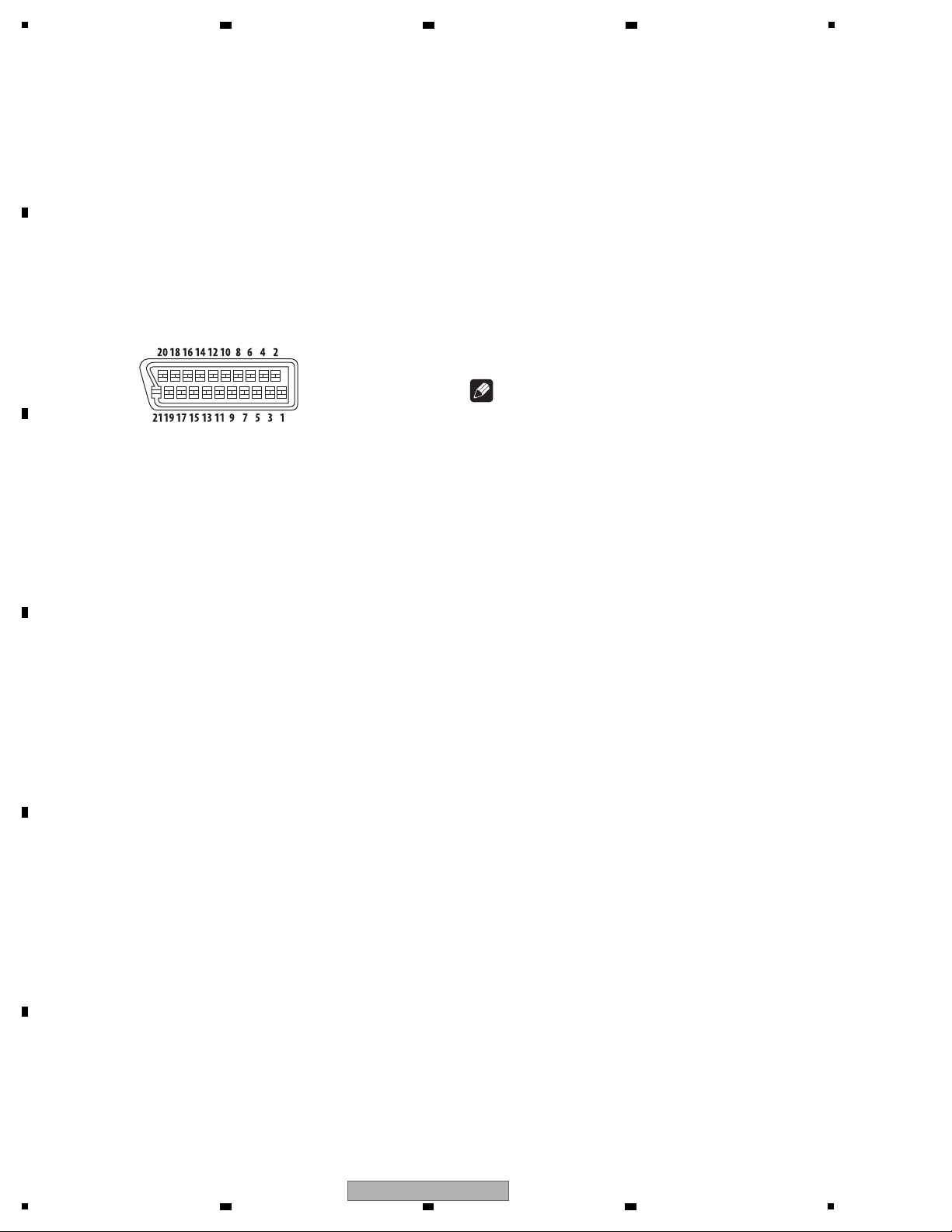
AV Connector (21-pin connector assignment)
AV connector output. . . . . . . . . . . . . . . . 21-pin connector
This connector provides the video and audio signals for
connection to a compatible colour TV or monitor.
PIN no.
1 . . . . . . . . . . . . . . . . . . . . . . . . . . . . . . . . . Audio 2/ R out
3 . . . . . . . . . . . . . . . . . . . . . . . . . . . . . . . . . .Audio 1/ L out
4 . . . . . . . . . . . . . . . . . . . . . . . . . . . . . . . . . . . . . . . . . GND
7 . . . . . . . . . . . . . . . . . . . . . . . . . . . . . . . . . . . . . . . . . B out
8 . . . . . . . . . . . . . . . . . . . . . . . . . . . . . . . . . . . . . . . . Status
11 . . . . . . . . . . . . . . . . . . . . . . . . . . . . . . . . . . . . . . . .G out
15 . . . . . . . . . . . . . . . . . . . . . . . . . . . . . . . . . . . . . . . .R out
17 . . . . . . . . . . . . . . . . . . . . . . . . . . . . . . . . . . . . . . . . GND
19 . . . . . . . . . . . . . . . . . . . . . . . . . . . . . . . . . . . . Video out
21 . . . . . . . . . . . . . . . . . . . . . . . . . . . . . . . . . . . . . . . . GND
Video output
Output level . . . . . . . . . . . . . . . . . . . . . . . . . 1 Vp-p (75 Ω)
Output terminal. . . . . . . . . . . . . . . . . . . . . . . RCA terminal
Component video output (Y, C
B / PB, CR / PR)
Y output level . . . . . . . . . . . . . . . . . . . . . . . . 1 Vp-p (75 Ω)
C
B
/ PB, CR/ PR output level. . . . . . . . . . . . .0.7 Vp-p (75 Ω)
Output terminal. . . . . . . . . . . . . . . . . . . . . . . RCA terminal
Audio output (stereo L/ R)
Audio output level. . . . . . . . . . 200 mVrms (1 kHz, -20 dB)
Output terminal. . . . . . . . . . . . . . . . . . . . . . . RCA terminal
Frequency response . . . . . . . . . . . . . . . . . 4 Hz to 44 kHz
S/ N ratio . . . . . . . . . . . . . . . . . . . . . . . . . . . . . . . . .114 dB
Dynamic range (DV-120). . . . . . . . . . . . . . . . . . . . . 87 dB
Dynamic range (DV-120K) . . . . . . . . . . . . . . . . . . . .84 dB
Total harmonic distortion (DV-120) . . . . . . . . . . . 0.007 %
Total harmonic distortion (DV-120K). . . . . . . . . . . 0.01 %
Wow and fl utter . . . . . . . . . . . . . Below measurable limits
(±
0.001 % W. PEAK)
Digital audio output
Coaxial digital output . . . . . . . . . . . . . . . . . . RCA terminal
Additional information
USB port. . . . . . . . . . . . . . . . . . . . . . . . . . . . . . . . . . A type
Notes
The specifi cations and design of this product are •
subject to change without notice.
This product includes FontAvenue•
®
fonts licensed
by NEC Corporation. FontAvenue is a registered
trademark of NEC Corporation.
Manufactured under license from Dolby Laboratories. •
Dolby and the double-D symbol are trademarks of
Dolby Laboratories.
Manufactured under license under U.S. Patent #: •
5,451,942 & other U.S. and worldwide patents issued
& pending. DTS and DTS Digital Out are registered
trademarks and the DTS logos and Symbol are
trademarks of DTS, Inc. © 1996-2008 DTS, Inc. All
Rights Reserved.
2. SPECIFICATIONS
2.1 SPECIFICATIONS
A
2 3 4
B
C
D
E
F
6
1
2 3 4
DV-120-K
5
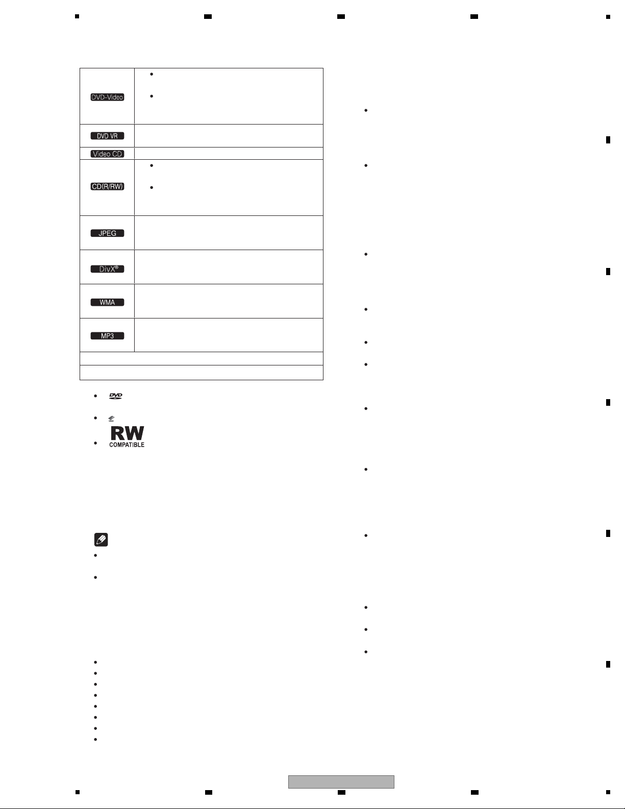
[1] Playable discs
Commercially available
DVD-Video discs
DVD-R/-RW/-R DL and DVD+R/
+RW/ +R DL discs recorded in
the Video mode and fi nalized
DVD-R/-RW/-R DL discs recorded in
the VR mode
Video CDs (including Super VCDs)
Commercially available audio
CDs
CD-R/-RW/-ROM discs containing
music recorded in the CD-DA
format
JPEG fi les recorded on DVD-R/-RW/
-R DL discs, CD-R/-RW/-ROM discs or
USB devices
DivX video fi les recorded on DVD-R/
-RW/-R DL discs, CD-R/-RW/-ROM
discs or USB devices
WMA fi les recorded on DVD-R/-RW/
-R DL discs, CD-R/-RW/-ROM discs or
USB devices
MP3 fi les recorded on DVD-R/-RW/
-R DL discs, CD-R/-RW/-ROM discs or
USB devices
Fujicolor CD
KODAK Picture CD
Discs that cannot be played
DVD Audio discs
DVD-RAM discs
SACDs
CD-G
Blu-ray discs
HD DVDs
Discs that have not been fi nalized
Discs recorded with packet writing
About region numbers
DVD player and DVD-Video discs are
assigned region numbers according to the
region in which they are sold. This player’s
region number(s) is (are) as shown below.
DVD-Video: 2
Discs not including these numbers cannot
be played.
Discs playable on this player are as shown
below.
DVDs: 2 (including 2) and ALL
Regarding copy protected CDs
This player is designed to conform to the
specifi cations of the audio CD format. This
player does not support the playback or function
of discs that do not conform to these specifi cations.
About playing DualDiscs
A DualDisc is a new two-sided disc, one
side of which contains DVD content —
video, audio, etc. — while the other side
contains non-DVD content such as digital
audio material.
The DVD side of a DualDisc can be played
on this player (excluding any DVD-Audio
content).
The non-DVD, audio side of the disc is not
compatible with this player.
It is possible that when loading or ejecting
a DualDisc, the opposite side to that
being played will be scratched. Scratched
discs may not be playable.
For more detailed information on the
DualDisc specifi cation, please refer to the
disc manufacturer or disc retailer.
Playing discs created on
computers or BD/ DVD recorders
It may not be possible to play discs
recorded using a computer due to the
application settings or computer’s
environment settings. Record discs in a
format playable on this player. For details,
contact the dealer.
It may not be possible to play discs
recorded using a computer or a BD/DVD
recorder, if burn quality is not good due to
characteristics of the disc, scratches, dirt
on the disc, dirt on the recorder’s lens, etc.
Playable fi les
Only discs recorded in ISO9660 Level 1,
Level 2 and Joliet can be played.
Files protected by DRM (Digital Rights
Management) cannot be played.
Files other than the ones below (WMV,
MPEG4-AAC,etc.) are not guaranteed to play.
is a trademark of DVD Format/Logo
Licensing Corporation.
is a trademark of FUJIFILM Corporation.
This label indicates playback compatibility
with DVD-RW discs recorded in VR format
(Video Recording format). However,
for discs recorded with a record-only-once
encrypted program, playback can only
be achieved using a CPRM compatible
device.
Notes
This player does not support multisession
discs or multiborder recording.
Multisession/ multiborder recording is a
method in which data is recorded on a single
disc in two or more sessions/borders. A
“session” or “border” is one recording unit,
consisting of a complete set of data from
lead-in to lead-out.
2.2 DISC/CONTENT FORMAT
6 7 8
A
5
DV-120-K
6 7 8
B
C
D
E
F
7
1
Playable fi le extensions
Video fi les
.divx .avi
Files not containing DivX video signals
cannot be played, even if they have the
extension “.avi”.
Image fi les
.jpg .jpeg
Audio fi les
.wma .mp3
Supported video fi le formats
DivX
DivX is a media technology created by
DivX, Inc. DivX media fi les contain image
data.
DivX fi les may also include such
advanced playback functions as menu
screens and selection of multiple subtitle
languages/audio tracks.
Plays DivX® video, including premium
content
DivX® is a registered trademark of DivX,
Inc., and is used under license.
Supported image fi le formats
JPEG
Resolution: Up to 3 072 x 2 048 pixels
This player supports baseline JPEG.
This player supports Exif Ver.2.2.
This player does not support progressive
JPEG.
Supported audio fi le formats
This player does not support VBR
(Variable Bit Rate).
This player does not support lossless
Windows Media Audio (WMA)
Sampling frequencies: 32 kHz, 44.1 kHz
and 48 kHz
Bit rate: Up to 192 kbps
Windows Media is either a registered trademark or
trademark of Microsoft Corporation in the United
States and/or other countries.
This product includes technology owned by
Microsoft Corporation and cannot be used or
distributed without a license from Microsoft
Licensing, Inc.
This player supports fi les encoded
using Windows Media Player Ver. 7/ 7.1,
Windows Media Player for Windows XP
and Windows Media Player 9 Series.
MPEG-1 Audio Layer 3 (MP3)
Sampling frequencies: 32 kHz, 44.1 kHz
and 48 kHz
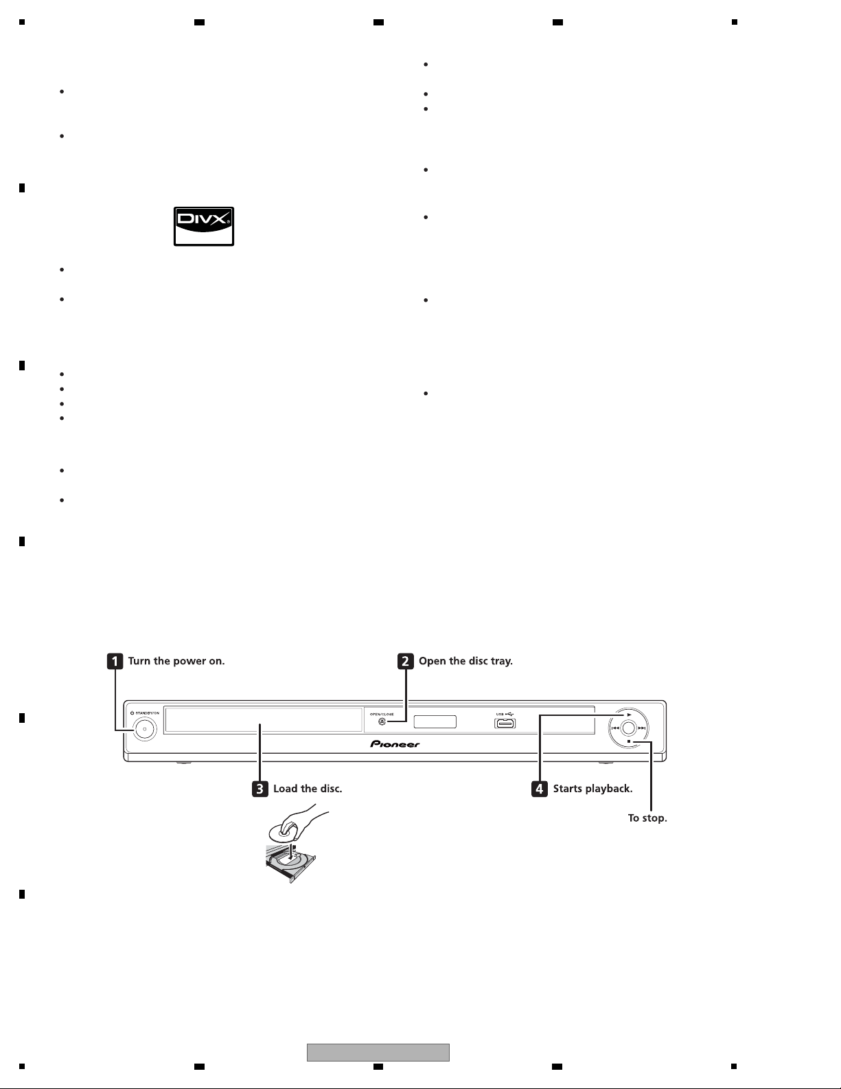
[1] Front panel
A
B
2 3 4
C
2.3 PANEL FACILITIES
D
E
F
8
1
DV-120-K
2 3 4
5
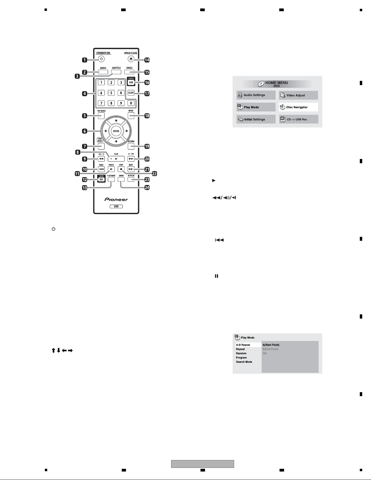
[2] Remote control
ENTER
Use this to implement the selected item or enter a
setting that you have changed.
7 HOME MENU
Press to display/ hide the Home Menu.
Audio Settings•
Video Adjust•
Play Mode•
Disc Navigator•
Initial Settings•
CD -> USB Rec•
8
PLAY
Press to start playback.
9
Press during playback to fast-reverse.•
Press in the pause mode to move backward frame-by-•
frame.
Press and hold in while in the pause mode for slow •
play in the reverse direction.
10
PREV
Press to return to the beginning of the currently
playing title, chapter, track or fi le. Press twice to
move back to the beginning of the previous title,
chapter, track or fi le.
11
PAUSE
Press to stop playback temporarily. Press again to
resume.
12 USB REC
Press to display the CD -> USB Rec.
13 PLAY MODE
Press to display/ hide the Play Mode screen.
1
STANDBY/ON
Press to turn the power on and off.
2 AUDIO
For discs or fi les including multiple audio streams/
channels, the audio stream/channel can be switched
during playback.
3 SUBTITLE
On DVD-Video or DivX discs containing subtitles
in multiple languages, the subtitle can be switched
during playback.
4 Number buttons (0 to 9)
Use these to specify and play the title, chapter, track
or fi le you want to view/listen to. Also use them to
select items on menu screens, etc.
5 TOP MENU
Press to display the top menu of the DVD-Video.
6
/ / /
Use these to select items, change settings and move
the cursor.
6 7 8
A
B
C
D
E
F
DV-120-K
5
6 7 8
9
1
A-B Repeat•
The specifi ed section within a single title or
track is played repeatedly.
Repeat•
Plays titles, chapters, tracks or fi les repeatedly.
Random•
Playes titles, chapters or tracks in random
order.
Program•
Plays titles, chapters, tracks or fi les in the order
in which you program them.
Search Mode•
Plays the specifi ed number or time within the
title, chapter, track or fi le.
The Play Mode function may not work for some
discs or fi les.
14
OPEN/CLOSE
Open the disc tray and load the disc.
15 ANGLE
On DVD-Video discs containing multiple angles, the
angle can be switched during playback.
16 DVD/USB
Press to switch between the DVD and USB modes.
17 CLE AR
Press to clear the selected item. Use this for example
if you input the wrong number.
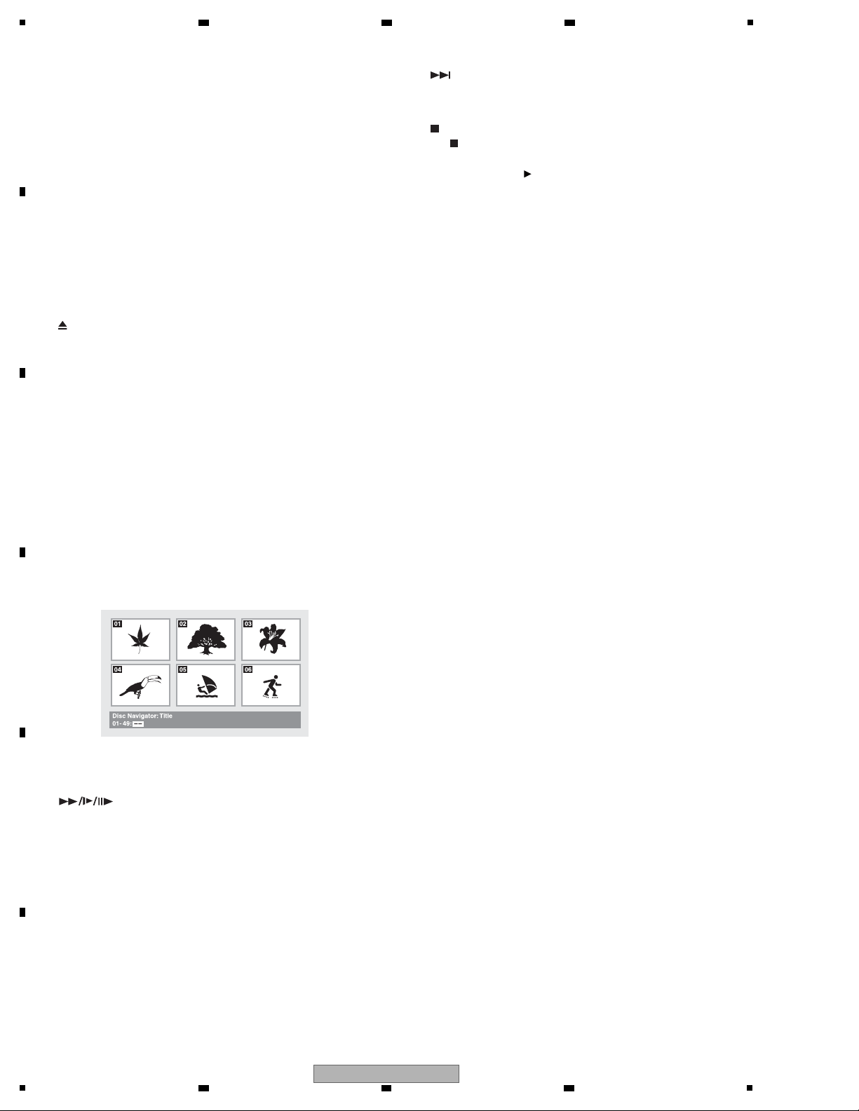
18 MENU
Press to display the menu screen or Disc Navigator.•
Select and play the title, chapter, track or fi le from the •
Disc Navigator.
Ex.: DVD video Disc Navigator
19 RETURN
Press to return to the previous screen.
20
Press during playback to fast-forward.•
Press in the pause mode to move forward frame-by-•
frame.
Press and hold in while in the pause mode for slow •
play in the forward direction.
21
NEXT
Press during playback to skips ahead to the beginning
of the next title, chapter, track or fi le.
22
STOP
When
STOP is pressed during playback, the
point at which playback was stopped is stored in
the memory. When
PLAY is pressed, playback
resumes from the point at which it was stopped.
23 DISPLAY
The elapsed time, amount remaining, etc., is
displayed.
24 ZOOM
Zooming on the image
A
B
C
D
2 3 4
E
F
10
1
DV-120-K
2 3 4
5
Item to be checked regarding video Item to be checked regarding audio
Block noise Distortion
Horizontal noise Noise
Dot noise Volume too low
Disturbed image (video jumpiness) Volume too high
Too dark Volume fluctuating
Too bright Sound interrupted
Mottled color
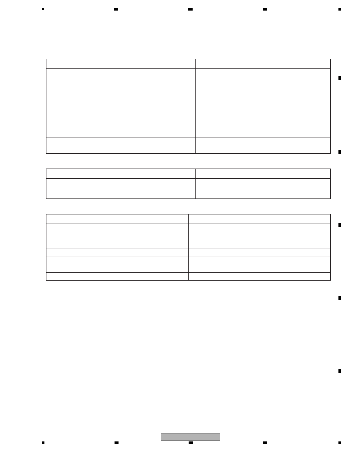
No. Procedures Check points
1
2
3
4
5
Confirm the firmware version on Test Mode. The version of the firmware must be latest.
Update firmware to the latest one, if it is not the latest.
Confirm whether the customer complain has been solved.
If the customer complain occurs with the specific disc, use it for
the operation check.
The customer complain must not be reappeared.
Video, audio and operations must be normal.
Play back a DVD.
(Menu operation, Title/chapter search)
Play back a CD.
(track search)
Audio and operations must be normal.
Video, audio and operations must be normal.
Check the appearance of the product. No scratches or dirt on its appearance after receiving it for
service.
Items to be checked after servicing / DV
To keep the product quality after servicing, confirm recommended check points shown below.
See the table below for the items to be checked regarding video and audio.
No. Procedures Check points
1
Confirm playback error rates at the innermost and outermost
tracks by using the following disc.
DVD test disc (GGV1025)
The error rates must be less than 5.0e-4.
(This procedure can determine if the drive is degraded.)
Specific Items to be Checked
6 7 8
3. BASIC ITEMS FOR SERVICE
3.1 CHECK POINTS AFTER SERVICING
A
B
C
D
E
F
DV-120-K
5
6 7 8
11
1
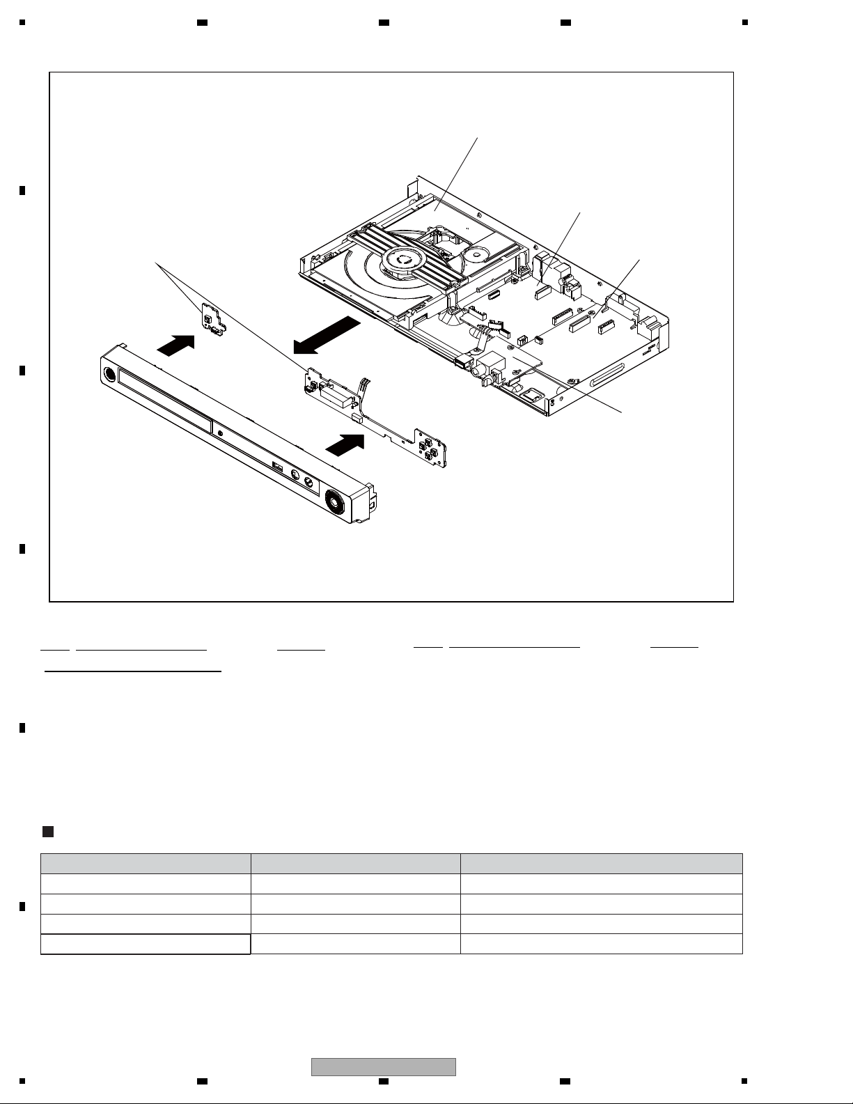
OPERATION PCB ASSY
POWER PCB ASSY
USB PCB ASSY
DVD MT PCB ASSY
DECK CD
Service Remote Control Unit GGF1381 diagnosis
Name Jig No. Remarks
DVD Test Disc (DVD-
Video,NTSC)
GGV1025 Operation Check
DVD Test Disc (DVD-Video,PAL)
CD Test Disc
GGV1101
STD-905
Operation Check
Operation Check
Jigs list
3.2 PCB LOCATIONS
A
B
2 3 4
C
D
Mark No. Description Part No.
LIST OF ASSEMBLIES
1..DVD MT PCB ASSY (YXZT5) A2M109A130
1..DVD MT PCB ASSY (SXZT) A2M101A130
1..OPERATION PCB ASSY (YXZT5) A2M109A270
1..OPERATION PCB ASSY (SXZT) A2M101A270
3.3 JIGS LIST
E
Mark No. Description Part No.
1..USB PCB ASSY (YXZT5) A2M109AFA0
1..USB PCB ASSY (SXZT) A2M101AFA0
> 1..POWER PCB ASSY (YXZT5) A2M109A240
> 1..POWER PCB ASSY (SXZT) A2M101A240
1..DECK CD 169B00047A
F
12
1
DV-120-K
2 3 4

5
6 7 8
A
B
C
D
E
F
DV-120-K
5
6 7 8
13

1
12
11
10
9
8
7
6
5
4
3
2
1
12
11
10
9
8
7
6
5
4
3
2
1
9
8
7
6
4
5
3
2
1
CP601
9
8
7
6
4
5
3
2
1
CP4002
17
16
15
14
13
12
11
10
9
8
7
6
4
5
3
2
1
CP4003
17
16
15
14
13
12
11
10
9
8
7
6
4
5
3
2
1
CP502
54321
54321
5
4
3
2
1
321
CP603
321
CP604
4
3
2
1
VR6501
MIC VOL
123
J6501MIC1
1
2
3
4
5
7
8
Vout
B+
GND
OS651
1
2
3
J8101
SCART
SXZT only
SXZT only
1
10
11
12
13
14
15
16
17
18
19
220
21 3
4
5
6
7
8
9
J501
AC INLET
12
CD501
AC220V-240V_50Hz/60Hz(EU)
H2
E
CVB
1
23
DEH159
PCB271
DEH158
PCB270
OPERATION PCB
DEH160
PCBFA0
USB/KARAOKE PCB
17
3
2
9
8
7
6
5
4
1
16
14
15
10
13
12
11
P.ON-H(STBY L)
P.ON-H(STBY L)
AT+3.3V
GND(D)
GND(D)
AT+3.3V
AT+3.3V
MIC
GND
P.CON+12V
GND
P.CON+5V
AT/P.CON+6V
AT/P.CON+6V
GND(M)
GND(M)
MIC IN-H
GND
OPERATION2 PCB
CD7301
3
2
7
6
5
4
1
3
2
7
6
5
4
1
9
8
10
12
11
9
8
12
11
10
A/V for 21PIN
VIDEO/AUDIO for 21PIN
CD601
3
2
9
8
7
6
5
4
1
3
2
9
8
7
6
5
4
1
CP8103
RGB-H
R
B
G
GND
CVBS
AUDIO R
GND
AUDIO L
FS
GND
GND
RGB-H
R
B
G
GND
CVBS
AUDIO R
GND
AUDIO L
FS
GND
GND
CP7301
DPH020
PCB240
POWER PCB
AT+3.3V
GND(D)
GND(D)
AT+3.3V
AT+3.3V
MIC
GND(M)
GND(M)
MIC IN-H
MIC_GND
P.CON+5V
AT/P.CON+6V
AT/P.CON+6V
P.CON+12V
GND
GND
17
16
15
14
13
3
2
9
8
7
6
5
4
1
12
11
10
CD502
DGND
IR
DGND
DGND
LEM_DIO
LEM_STB
LEM_CLK
EV+3.3/6V
EV+3.3/6V
DGND
IR
DGND
DGND
LEM_DIO
LEM_STB
LEM_CLK
EV+3.3/6V
EV+3.3/6V
NC
NC
NC
NC
NC
(CD504)
55
44
33
22
11
(CP504)
MIC
GNDA
GNDA
MIC IN-H
5V
(CP6501)
MIC
GNDA
GNDA
MIC IN-H
5V
CP6602
CP6601
USBP
USBN
PGND
VBUS
GND(SHIELD)
+5V
USB_DN
USB_DP
GND
COMMAND TRANSMITTER
TM101
POWER
SW2
GND
321
321
POWER
SW2
GND
D
(
(
(
OPERATION
PCB ASSY
(A2M109A270 : YXZT5)
(A2M101A270 : SXZT)
USB PCB ASSY
(A2M109AFA0 : YXZT5)
(A2M101AFA0 : SXZT)
POWER PCB ASSY
(1/2, 2/2)
(A2M109A240 : YXZT5)
(A2M101A240 : SXZT)
2 3 4
4. BLOCK DIAGRAM
4.1 OVERALL WIRING DIAGRAM
A
B
C
D
E
F
14
DV-120-K
1
2 3 4

5
9
8
7
6
4
5
3
2
1
CP2302
LOAD/SLED/SPINDLE
5
4
3
2
1
24
23
22
21
20
19
2
1
18
17
16
15
14
13
12
11
10
9
8
7
6
5
4
3
CP2301
PICK-UP(GOLD)
H1H2EH1H2
E
J7302
CVBS/Y/U/V
1
23
4
56
H
E
J8001
COAXIAL
1
2
H1H2
E
J8003
AUDIO OUT
1
23
V
DMJ113
PCB130
DVD MT PCB
or 21PIN
GND(SHIELD)
VBUS
PGND
USBN
USBP
CP4004
LOAD+
LOAD-
SW_OUT
COM
SW_IN
SPD-
SPD+
SLD-
SLD+
NC
CD-VR(780)
NC
VCC
E
MPD
VC
GND
F
B
A
CD-LD(780)
DVD-VR(650)
HFM-VCC
RF
SW
D
C
T-
T+
F+
F-
LD-GND
DVD-LD(650)
DVD MT PCB ASSY
(1/6 - 6/6)
(A2M109A130 : YXZT5)
(A2M101A130 : SXZT)
DECK CD
(169B00047A)
ATTENTION
: LES PIECES REPAREES PAR UN ETANT
DANGEREUSES AN POINT DE VUE SECURITE
NUTILISER QUE CELLS DECRITES
DANS LA NOMENCLATURE DES PIECES
CAUTION
: SINCE THESE PARTS MARKED BY ARE
CRITICAL FOR SAFETY, USE ONES
DESCRIBED IN PARTS LIST ONLY
NOTE: THE DC VOLTAGE EACH PART WAS
MEASURED WITH THE DIGITAL TESTER
DURING PLAYBACK.
NOTE: THIS SCHEMATIC DIAGRAM IS THE LATEST AT THE TIME
OF PRINTING AND SUBJECT TO CHANGE WITHOUT NOTICE
6 7 8
A
B
C
D
5
6 7 8
DV-120-K
E
F
15

1
P. C O N+12V
AC220V~240V
X4001
27MHz
AT+3.3V
P. C O N+6V
P. C O N+5V
POWER
SUPPLY
DVD LOADER
MOTOR DRIVER
IC2301
AM5766
LEM DRIVER
IC601
ET6202
FIP(V651)
GYXS-2511CG
KEY
SERVO
RF
SERVO
IR
LEM_STB,
LEM_SCL,LEM_DIO
RESET
DVD_LD,
CD_LD
IR
108MHz
TV Encoder
MPEG-1/2/
JPEG
VIDEO
DECORDER
RF
IR RECEIVER (OS651)
KSM-2001TC2P
16M SERIAL FLASH
IC4004
ES25M16A
64Mbit SDRAM
IC4005
M12L64164A-5TG2R
XAMUTE
MPEG/MICON
IC4001
MT1389FE/L-L
AUDIO CODEC/
INTERNAL DAC
+1.8V
SFLASH_CS,DO,CK,DI
MA0~MA11,
DQ0~DQ15
RESET IC
IC4003
R3112N291A-TR-FA
L
R
AUDIO AMP IC
IC8003
NJM4565M(TE1)
AUDIO_L,
AUDIO_R
VIDEO DRIVER
IC7303
MM1510XNRE
MIC1
MIC AMP IC
IC6503
NJM4565M(TE1)
MIX AMP IC
IC6501
RC4580IDR
ASPDIF
CO
COAXIAL
21PIN
RGB OUT
V
CVBS
U
Y
4CH BUS SW IC
IC7302
TC7MB3257FT(EL,M
MIC VOL
VR6501
VIDEO DRIVER
IC7301
MM1510XNRE
CVBS
R/CR,B/CB,G/Y
21PIN_CVBS
OVERALL BLOCK DIAGRAM
2 3 4
4.2 OVERALL BLOCK DIAGRAM
A
B
C
D
E
F
16
1
2 3 4
DV-120-K

5
DVD LOADER/MPEG BLOCK DIAGRAM
DVD
Loader
MPEG/MICON IC
IC4001
MT1389FE/L-L
IOA, V20
C
RF, A, B, C, D, E, F, MDI1
DVD_LD, CD_LD
Q2302,2303
CD,DVD
LDO1, LDO2
MOTOR DRIVER IC
IC2301
AM5766
DMSO, FMSO,
TROPEN, TRCLOSE,
TRSO, FOSO,
STBY, V1P4
T+/-, F+/-,
LOAD+/-,
MOT_SLED+/-,
MOT_SPDL+/-
OPU
SPINDLE/
STEPING/
SLED
MOTOR
TROUT, TRIN, OP+/-
16M SERIAL FLASH
IC4004
ES25M16A
MA0~MA11, DQ0~DQ15,
DQM0, DQM1, DBA0,DBA1,
SDCLK,DWE#,DRAS#, DCAS#
A
D
SFLASH_CS,SFLASH_DO,
SFLASH_CK,SFLASH_DI
64Mbit SDRAM
IC4005
M12L64164A-5TG2R
A
A
VIDEO DRIVER
IC7301
MM1510XNRE
A, B
3
5
Y
U
CVBS/Y/U/V
J7302
2
V
6
CVBS
A.......AT+3.3V
B.......+1.8V
C.......P.CON+5V
D.......P.CON+6V
E.......AT+12V
F.......P.CON+12V
G.......V+5V
IR
IR RECEIVER (OS651)
KSM-2001TC2P
IR
GR1~5, S1~7,DP
LEM DRIVER
IC601
ET6202
FIP (V651)
GYXS-2511CG
A
A
AUDIO AMP IC
IC8003
NJM4565M(TE1)
3
2
R
L
AUDIO JACK
J8003
AUDIO R
AUDIO L
AUDIO L, R
F
X4001
27MHz
19
CVBS
21PIN CONNECTOR
J8101
11
15
R OUT
G OUT
16
7
B OUT3L
4CH BUS SW IC
IC7302
TC7MB3257FT(EL,M
D
CVBS
G/Y,B/CB,R/CR
1
R
8
21 PIN_ CTL
BLANKING_OUT
Q7305, Q7306
COAXIAL JACK
J8001
ASPDIF
RESET
RESET IC
IC4003
R3112N291A-
TR-FA
A
MIX AMP IC
IC6501
RC4580IDR
MIC AMP IC
IC6503
NJM4565M(TE1)
2
4
3
7
1
8
5
MIC1
J6501
3
1
2
MIC VOL
VR6501
G
G
XAMUTE
Q8013
XAMUTE
Q7301
2
MIC
MIC IN-H
G
VIDEO DRIVER
IC7303
MM1510XNRE
G
LEM_STB,LEM_SCL,
LEM_DIO
6 7 8
4.3 DVD LOADER/MPEG BLOCK DIAGRAM
A
B
C
D
E
F
17
DV-120-K
5
6 7 8

1
POWER BLOCK DIAGRAM
AC IN
AT+3.3V
P.CON+6V
P.CON+5V
P.CON+12V
P. O N-H
VOLTAGE CTL
IC501
KIA431A-AT
POWER CTL
IC502
STR-A6159M
+5V REG
(DVD MOTOR)
IC503
PQ070XF01SZH
REG+1.8V
IC4006
LD1117AL-ADJ-AA3-A-R
+1.8V
SWITCHING
TRANS
T501
PHOTO COUPLER
IC504
PS2561AL1-1-V (W)
Q510
P.CON +12V SW
4.4 POWER BLOCK DIAGRAM
A
2 3 4
B
C
D
E
F
18
DV-120-K
1
2 3 4

5
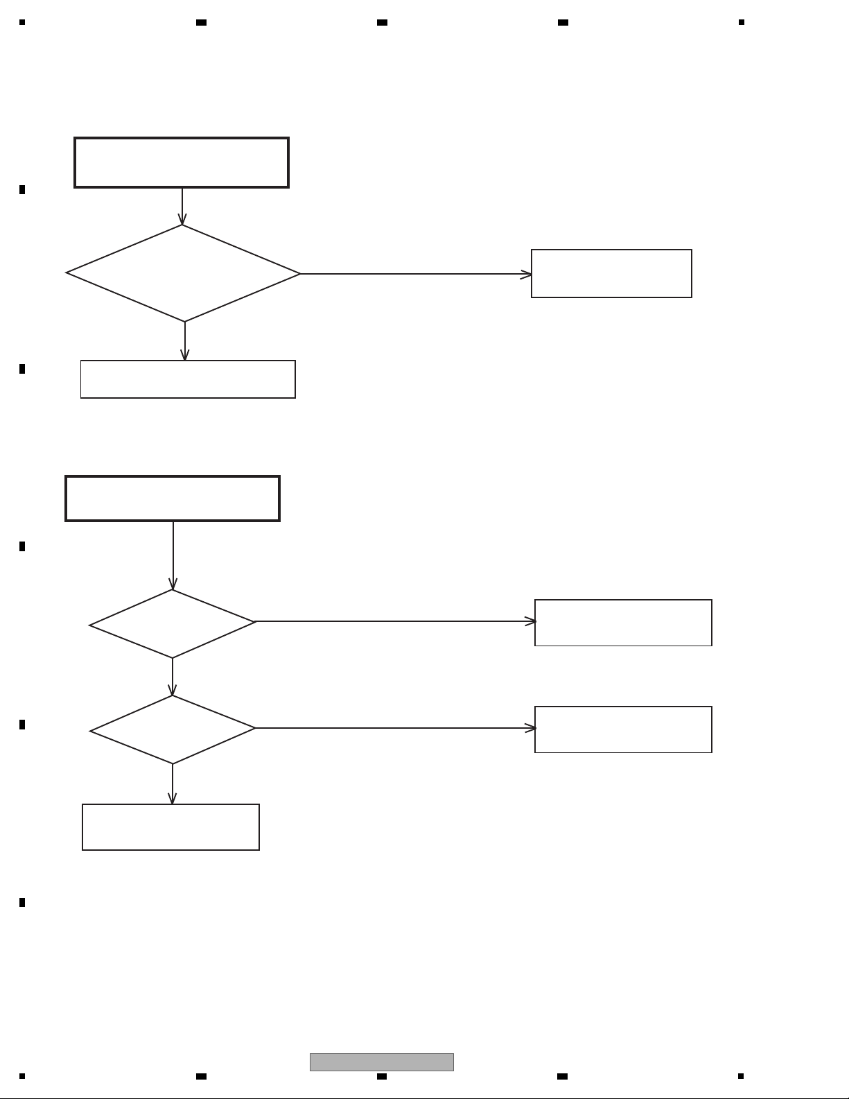
POWER DOES NOT TURN ON
Is the voltage at
pin 1,2 and pin 3 of CP502 about 3.3V
and at pin 11 of CP502
about 5V?
No
Ye s
No
Is there waveform at
X4001 about 3.0Vp-p ?
Check X4001, IC4001 and
peripheral circuit.
Ye s
Write DVD FIRMWARE DATA.
Check AT+3.3V line of POWER BLOCK.
Check IC503 and peripheral circuit.
No
Ye s
No
DECK DOES NOT ACCEPT
OPEN/CLOSE
Check P.CON 6V line of
POWER BLOCK.
Ye s
Is the lose connection
at CP2302 to DECK ?
Check CP2302
connection to DECK.
Change DVD LOADER.
Is the voltage at
pin 8 and 19 of IC2301
about DC6V ?
5. DIAGNOSIS
5.1 TROUBLE SHOOTING
6 7 8
A
B
C
D
DV-120-K
5
6 7 8
E
F
19
1
DOES NOT LIGHT ON DISPLAY
Ye s
Is the voltage at
pin 7 and pin 21 of IC601
about 3.0V ?
Check AT+3.3V line of
POWER BLOCK.
No
Replace V651 or IC601.
NO PLAYBACK PICTURE OF AV
JACK
Is there
video signal at pins 1 and 2
of IC7301 ?
Change IC7301.
No
Ye s
No
Ye s
Check J7302 and peripheral
circuit.
Is there
a signal at pin 99 of
IC4001 ?
Check IC4001 and
peripheral circuit.
A
B
2 3 4
C
D
E
F
20
1
2 3 4
DV-120-K
 Loading...