

Page 1
¢§ 4
6
DVD PLAYER
DV-09
DV-S9
THIS MANUAL IS APPLICABLE TO THE FOLLOWING MODEL(S) AND TYPE(S).
Type
KU/CA
L/TA
DV-09
–
Model
DV-S9
–
AC120V
AC110V
Power Requirement
1
3
Region restriction code
(region number)
ORDER NO.
RRV1944
•
Refer to the service guide RRV1896 for DV-505.
IC information is described in the service guide.
CONTENTS
1. SAFETY INFORMATION
2. EXPLODED VIEWS AND PARTS LIST
3. SCHEMATIC DIAGRAM
4. PCB CONNECTION DIAGRAM
5. PCB PARTS LIST
6. ADJUSTMENT
PIONEER ELECTRONIC CORPORATION 4-1, Meguro 1-Chome, Meguro-ku, Tokyo 153-8654, Japan
PIONEER ELECTRONICS SERVICE, INC. P.O. Box 1760, Long Beach, CA 90801-1760, U.S.A.
PIONEER ELECTRONIC (EUROPE) N.V. Haven 1087, Keetberglaan 1, 9120 Melsele, Belgium
PIONEER ELECTRONICS ASIACENTRE PTE. LTD. 501 Orchard Road, #10-00 Wheelock Place, Singapore 238880
PIONEER ELECTRONIC CORPORATION 1998
...............................................
....................................................
......................................
................
.....................................
..........................
14
34
49
58
2
3
7. GENERAL INFORMATION
7.1 PARTS
7.1.1 IC
7.1.2 DISPLAY
7.2 DISASSEMBLY
7.3 BLOCK DIAGRAM
8. PANEL FACILITIES AND SPECIFICATIONS
.........................................................
...........................................................
................................................
...........................................
T – ZZM APR. 1998 Printed in Japan
................................
.......................................
....
67
67
67
73
74
78
79
Page 2
DV-09, DV-S9
1. SAFETY INFORMATION
This service manual is intended for qualified service technicians ; it is not meant for the casual do-ityourselfer. Qualified technicians have the necessary test equipment and tools, and have been trained
to properly and safely repair complex products such as those covered by this manual.
Improperly performed repairs can adversely affect the safety and reliability of the product and may
void the warranty. If you are not qualified to perform the repair of this product properly and safely, you
should not risk trying to do so and refer the repair to a qualified service technician.
WARNING
Lead in solder used in this product is listed by the California Health and Welfare agency as a known reproductive toxicant which may
cause birth defects or other reproductive harm (California Health & Safety Code, Section 25249.5).
When servicing or handling circuit boards and other components which contain lead in solder, avoid unprotected skin contact with
the solder. Also, when soldering do not inhale any smoke or fumes produced.
NOTICE
(FOR CANADIAN MODEL ONLY)
Fuse symbols (fast operating fuse) and/or
(slow operating fuse) on PCB indicate that replacement parts
must be of identical designation.
REMARQUE
(POUR MODÈLE CANADIEN SEULEMENT)
Les symboles de fusible (fusible de type rapide) et/ou
(fusible de type lent) sur CCI indiquent que les pièces
de remplacement doivent avoir la même désignation.
IMPORTANT
THIS PIONNER APPARATUS CONTAINS
LASER OF CLASS 1.
SERVICING OPERATION OF THE APPARATUS
SHOULD BE DONE BY A SPECIALLY
INSTRUCTED PERSON.
LASER DIODE CHARACTERISTICS
MAXIMUM OUTPUT POWER : 7 mw
WAVELENGTH : 650 nm
(FOR USA MODEL ONLY)
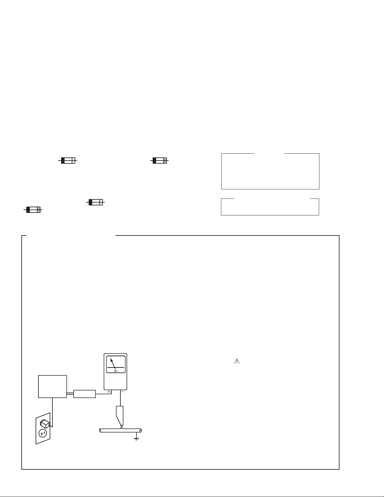
1. SAFETY PRECAUTIONS
The following check should be performed for the
continued protection of the customer and service
technician.
LEAKAGE CURRENT CHECK
Measure leakage current to a known earth ground (water
pipe, conduit, etc.) by connecting a leakage current tester
such as Simpson Model 229-2 or equivalent between the
earth ground and all exposed metal parts of the appliance
(input/output terminals, screwheads, metal overlays, control
shaft, etc.). Plug the AC line cord of the appliance directly
into a 120V AC 60Hz outlet and turn the AC power switch
on. Any current measured must not exceed 0.5mA.
Reading should
not be above
0.5mA
Earth
ground
Device
under
test
Also test with
plug reversed
(Using AC adapter
plug as required)
Leakage
current
tester
Test all
exposed metal
surfaces
ANY MEASUREMENTS NOT WITHIN THE LIMITS
OUTLINED ABOVE ARE INDICATIVE OF A POTENTIAL
SHOCK HAZARD AND MUST BE CORRECTED BEFORE
RETURNING THE APPLIANCE TO THE CUSTOMER.
2. PRODUCT SAFETY NOTICE
Many electrical and mechanical parts in the appliance
have special safety related characteristics. These are
often not evident from visual inspection nor the protection
afforded by them necessarily can be obtained by using
replacement components rated for voltage, wattage, etc.
Replacement parts which have these special safety
characteristics are identified in this Service Manual.
Electrical components having such features are identified
by marking with a
in this Service Manual.
The use of a substitute replacement component which does
not have the same safety characteristics as the PIONEER
recommended replacement one, shown in the parts list in
this Service Manual, may create shock, fire, or other hazards.
Product Safety is continuously under review and new
instructions are issued from time to time. For the latest
information, always consult the current PIONEER Service
Manual. A subscription to, or additional copies of, PIONEER
Service Manual may be obtained at a nominal charge from
PIONEER.
on the schematics and on the parts list
AC Leakage Test
2
Page 3
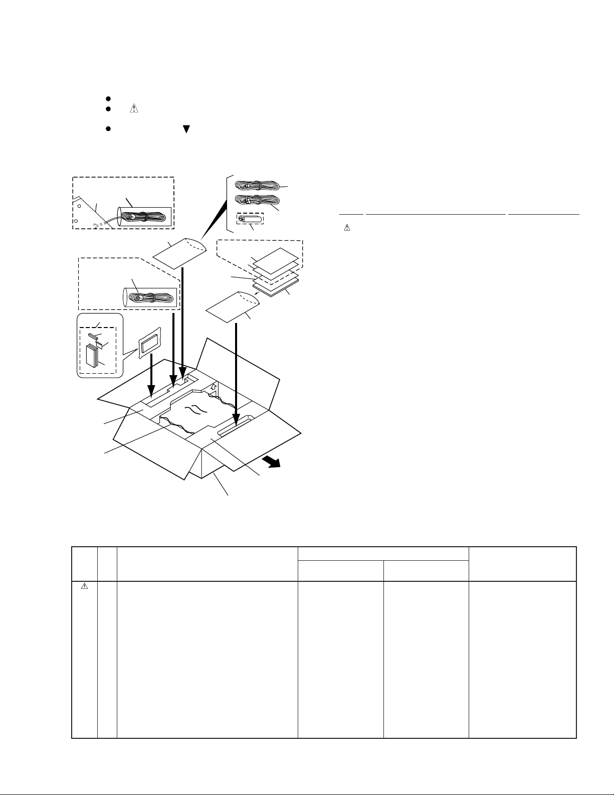
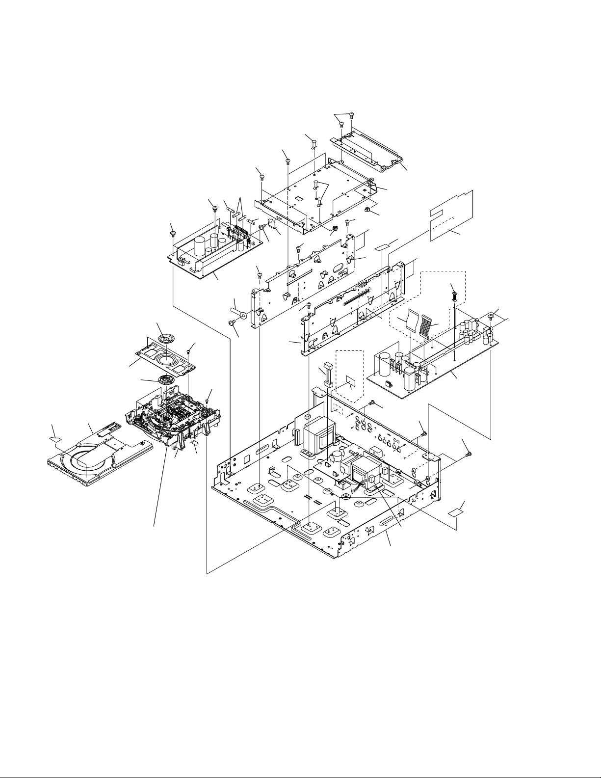
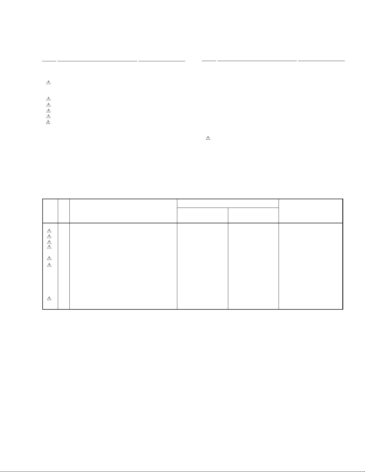
2. EXPLODED VIEWS AND PARTS LIST
NOTES:
2.1 PACKING
Parts marked by "NSP" are generally unavailable because they are not in our Master Spare Parts List.
The mark found on some component parts indicates the importance of the safety factor of the part.
Therefore, when replacing, be sure to use parts of identical designation.
Screws adjacent to mark on product are used for disassembly.
DV-09, DV-S9
Rear
Rear
Panel
Panel
DV-S9 only
8
11
9
10
13
15
DV-09 only
17
1
16
DV-09 only
2
(DV-S9 only)
5
(1) PACKING PARTS LIST
6
7
18
3
4
16
Front
12
Mark No. Description Part No.
NSP 2 Regular User’s Card See Contrast table (2)
NSP 3 Warranty Card See Contrast table (2)
NSP 7 Dry Cell Battery (R03, AAA) VEM-022
NSP 11 Filter VNK2063
NSP 18 Caution Card See Contrast table (2)
1 Power Cord See Contrast table (2)
4 Operating Instructions See Contrast table (2)
5 Audio Cord (L=1.5m) VDE1023
6 Video Cord (L=1.5m) VDE1024
8 Remote Control Unit See Contrast table (2)
9 Battery Cover See Contrast table (2)
10 Case (Below) See Contrast table (2)
12 Pad (F) See Contrast table (2)
13 Pad (R) See Contrast table (2)
14 Packing Case See Contrast table (2)
15 Mirror Mat Sheet VHL1018
16 Polyethylene Bag Z21-038
(0.03x230x340)
17 Mirror Mat Bag See Contrast table (2)
14
(2) CONTRAST TABLE
DV-09/KU/CA and DV-S9/L/TA are constructed the same except for the following :
.oNtraP
kraM.oNnoitpircseDdnalobmyS
1
PSN
2
PSN
3
4
4
8
8
9
01
21
31
41
71
PSN
81
)F(daP
)R(daP
droCrewoP
draCs'resUralugeR
draCytnarraW
)hsilgnE(snoitcurtsnIgnitarepO
)esenihC(snoitcurtsnIgnitarepO
)110VD-UC(tinUlortnoCetomeR
)010VD-UC(tinUlortnoCetomeR
revoCyrettaB
)woleB(esaC
esaCgnikcaP
gaBtaMrorriM
draCnoituaC
90-VD
AC/UK/
desutoN
desutoN
6201YRA
8811BRV
desutoN
2352XXV
desutoN
6822KND
2602KNV
8121AHV
9121AHV
3371GHV
4001LHV
1101NRV
9S-VD
AT/L/
3107GDA
0111YRV
desutoN
desutoN
1701CRV
desutoN
5252XXV
7714KNV
8714KNV
0121AHV
1121AHV
4571GHV
desutoN
desutoN
skrameR
3
Page 4
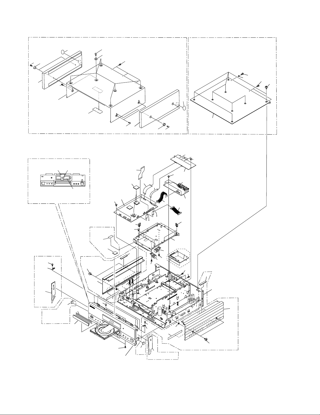
DV-09, DV-S9
2.2 EXTERIOR SECTION
DV-09 only
41
33
34
DV-09 only
20
262026
DV-09 only
36
DV-S9 only
23
45
43 44
Rear view
13
38
FL Filter
24
40
DV-09 only
DV-S9 only
22
11
46
20
20
39
42
31
19
25
DV-S9 only
20
20
30
38
10
23
35
5
32
1
16
33
41
A
B
20
20
3
6
C
7
2
9
16
from
Pickup Assy
from
Mecha.
8
21
15
DV-S9 only
4
21
20
B
C
29
Refer to
"2.3 BOTTOM VIEW
28
29
27
21
17
18
21
A
SECTION (1)".
12
20
22
13
20
26
37
DV-09 only
31
25
DV-S9 only
22
14
19
Refer to
"2.5 FRONT PANEL SECTION".
4
Page 5
(1) EXTERIOR SECTION PARTS LIST
DV-09, DV-S9
Mark No. Description Part No.
1 DVD MAIN Assy VWS1337
2 DOUT Assy See Contrast table (2)
3 VOUT Assy VWG1905
4 DIRB Assy See Contrast table (2)
5 Flexible Cable (28P) See Contrast table (2)
6 Flexible Cable (19P) VDA1666
(DVD MAIN CN508-VOUT CN601)
7 Flexible Cable (9P) VDA1665
(DVD MAIN CN507-VOUT CN602)
8 Housing Assy (12P) VKP2173
(DVD MAIN CN506-DOUT CN701)
9 Housing Assy (13P) See Contrast table (2)
10 Top Aluminum See Contrast table (2)
11 Side Aluminum L See Contrast table (2)
12 Side Aluminum R See Contrast table (2)
NSP 13 Cushion See Contrast table (2)
14 Tray Panel See Contrast table (2)
15 Main Shield VNE2137
NSP 16 Wire Clip VEC1181
17 FTS Heat Sink VNH1053
18 AV1 Heat Sink VNH1052
19 Screw BBP30P080FMC
20 Screw ABZ30P080FCC
21 Screw BBT30P080FCC
22 SH Screw See Contrast table (2)
23 Screw See Contrast table (2)
Mark No. Description Part No.
24 Door Packing VEC1995
25 Washer See Contrast table (2)
26 Top Stay VNE2139
27 Housing Assy (7P) VKP2177
(DVD MAIN CN502-SYPS CN32)
28 Housing Assy (8P) VKP2170
(DVD MAIN CN501-SYPS CN33)
29 Damper See Contrast table (2)
30 Washer WH30FUC
31 Cushion See Contrast table (2)
32 Gap Pad VEC1997
33 Wood Coller See Contrast table (2)
34 Side Wood L See Contrast table (2)
35 Side Wood R See Contrast table (2)
36 Gold Mole L See Contrast table (2)
37 Gold MoleR See Contrast table (2)
38 UL Caution Card See Contrast table (2)
39 Washer See Contrast table (2)
40 65 Label See Contrast table (2)
41 Screw See Contrast table (2)
NSP 42 Rubber Spacer See Contrast table (2)
NSP 43 Spacer A See Contrast table (2)
NSP 44 Spacer B See Contrast table (2)
45 Bonnet S See Contrast table (2)
46 Fuse Caution Label See Contrast table (2)
(2) CONTRAST TABLE
DV-09/KU/CA and DV-S9/L/TA are constructed the same except for the following :
.oNtraP
kraM.oNnoitpircseDdnalobmyS
2
4
5
9
01
yssATUOD
yssABRID
)P82(elbaCelbixelF
)P31(yssAgnisuoH
munimulApoT
90-VD
AC/UK/
2091GWV
desutoN
3661ADV
2712PKV
desutoN
9S-VD
AT/L/
1091GWV
7981GWV
2661ADV
1712PKV
8821HAV
skrameR
11
21
PSN
31
41
22
32
52
92
13
33
43
53
63
73
83
93
04
14
PSN
24
PSN
34
PSN
44
54
64
noihsuC
wercS
rehsaW
repmaD
noihsuC
rehsaW
wercS
LmunimulAediS
RmunimulAediS
lenaPyarT
wercSHS
relloCdooW
LdooWediS
RdooWediS
LeloMdloG
ReloMdloG
draCnoituaCLU
lebaL56
recapSrebbuR
ArecapS
BrecapS
StennoB
lebaLnoituaCesuF
desutoN
desutoN
desutoN
2424KNV
desutoN
KZF080P04ZBB
desutoN
desutoN
desutoN
8321WNP
2301PAV
3301PAV
5921HAV
6921HAV
313-XAA
9001EBA
9601WRO
8301ABP
2521BEV
7821BEV
8821BEV
2852XXV
8271WRV
6821HAV
7821HAV
5111BED
1424KNV
9401ABP
desutoN
061M071F58AW
2711BEV
6991CEV
desutoN
desutoN
desutoN
desutoN
desutoN
desutoN
desutoN
desutoN
desutoN
desutoN
desutoN
desutoN
desutoN
desutoN
5
Page 6
DV-09, DV-S9
2.3 BOTTOM VIEW SECTION (1/2)
29
33
4
27
26
21
28
21
19
20
11
10
28
27
4
2225
18
27
26
16
DV-09
only
35
28
28
1
30
7
34
8
9
28
A
14
3
27
17
22
A
24
32
B
23
28
DV-S9
6
only
5
2
28
26
28
C
B
C
24
Refer to
"2.6 LOADING MECHANISM ASSY".
6
15
Refer to
"2.4 BOTTOM VIEW SECTION (2/2)".
Page 7
(1) BOTTOM VIEW SECTION (1/2) PARTS LIST
Mark No. Description Part No.
1 SYPS Assy VWR1289
2 AUDIO Assy See Contrast table (2)
NSP 3 Loading Mechanism Assy VWT1150
4 Fuse (FU3, FU4 : 3A) REK1080
5 Housing Assy (13P) See Contrast table (2)
(AUDIO CN101-DIRB CN811)
6 Flexible Cable (28P) See Contrast table (2)
(AUDIO CN111-DIRB CN812)
7 Clamper Plate VNE2068
8 Bridge VNE2069
9 Clamper VNL1738
10 Tray See Contrast table (2)
11 Tray Label VRW1628
12 •••••
13 •••••
14 Flexible Cable (12P) VDA1664
(LOSB CN301-DVD MAIN CN107)
15 Housing Assy (4P) See Contrast table (2)
(AUDIO CN351-TRSA CN12)
DV-09, DV-S9
Mark No. Description Part No.
16 Housing Assy (3P) See Contrast table (2)
(LSFB CN2-TRSB CN21)
17 Side Wall L VNE2135
18 Side Wall R VNE2136
19 Trans. Shield VNE2138
20 Main Shield VNE2137
NSP 21 Card Spacer QEC1012
22 PCB Fixing Base DEC1231
23 PCB Holder See Contrast table (2)
24 Sheet VEX1022
25 Earth Plate B VBK1076
26 Screw BBT30P080FCC
27 Screw BBZ30P060FZK
28 Screw ABZ30P080FCC
29 Screw BBP30P080FMC
30 Cord Clamper RNH-184
31 •••••
32 Sheet VEC1991
33 Fuse (FU5, FU6 : 2A) REK1078
34 Screw BPZ26P080FZK
NSP 35 Fuse Caution Label See Contrast table (2)
(2) CONTRAST TABLE
DV-09/KU/CA and DV-S9/L/TA are constructed the same except for the following :
.oNtraP
kraM.oNnoitpircseDdnalobmyS
2
5
6
01
yarT
51
61
32
PSN
53
yssAOIDUA
)P31(yssAgnisuoH
)P82(elbaCelbixelF
)P4(yssAgnisuoH
)P3(yssAgnisuoH
redloHBCP
lebaLnoituaCesuF
90-VD
AC/UK/
1951VWV
desutoN
desutoN
4424KNV
5812PKV
2912PKV
desutoN
845-WRV
9S-VD
AT/L/
0951VWV
1712PKV
2661ADV
3424KNV
7812PKV
6612PKV
4261CEV
desutoN
skrameR
)218NCBRID-101NCOIDUA(
)118NCBRID-111NCOIDUA(
)21NCASRT-153NCOIDUA(
)12NCBSRT-2NCBFSL(
7
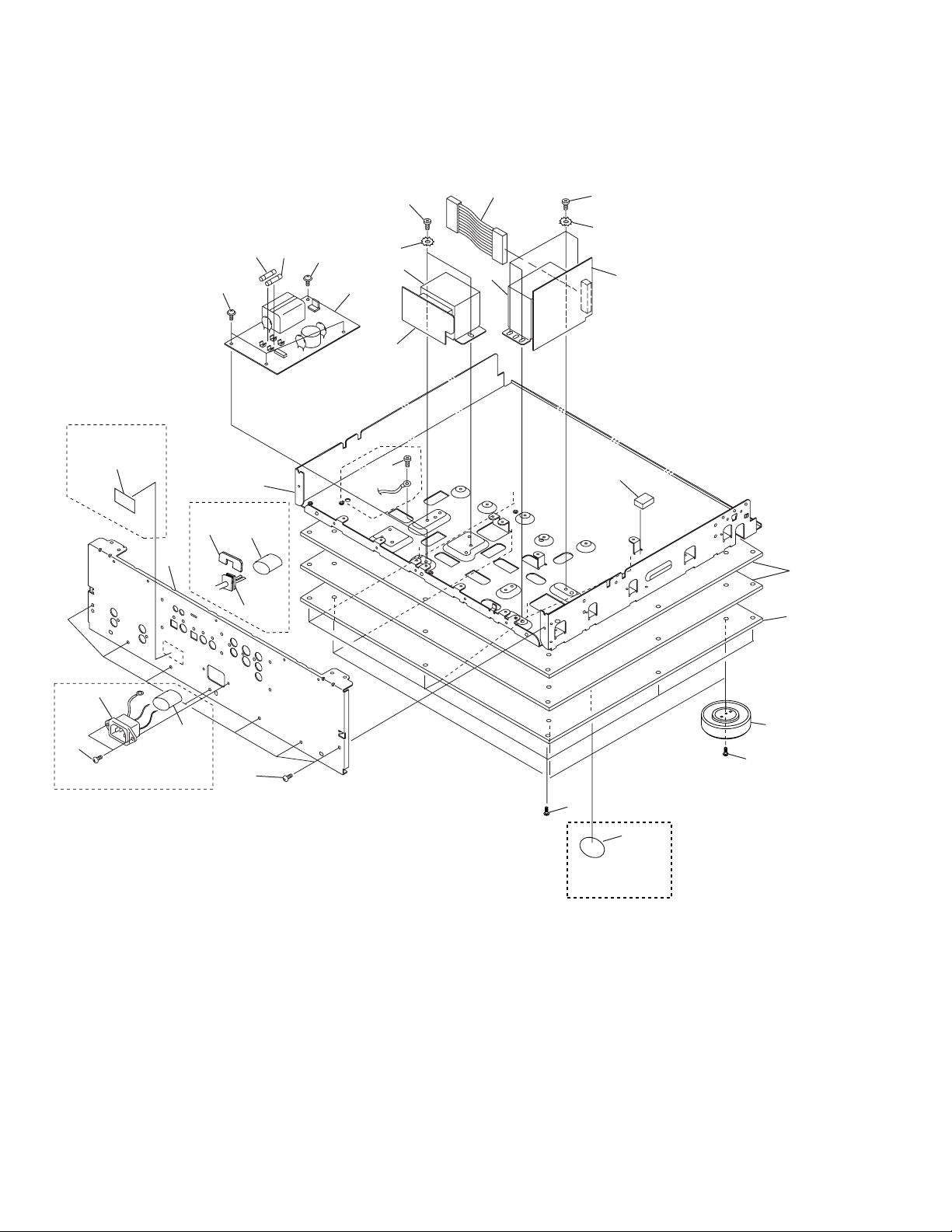
Page 8
DV-09, DV-S9
2.4 BOTTOM VIEW SECTION (2/2)
• Rear View
DV-S9 only
27
11
16
12
DV-09 only
5
25
26
17
3
DV-S9
only
18
7
1
17
4
9
19
10
16
28
28
15
13
14
20
6
DV-S9 only
5
20
23
24
DV-09 only
21
22
8
Page 9
(1) BOTTOM VIEW SECTION (2/2) PARTS LIST
Mark No. Description Part No.
NSP 1 TRSA Assy See Contrast table (2)
NSP 2 TRSB Assy VWR1300
NSP 3 LSFB Assy VWR1293
4 Fuse (FU2 : 1A) REK1075
5 UL Tube VEC1651
6 AC Inlet Assy (3P) See Contrast table (2)
7 Power Transformer (Audio) See Contrast table (2)
8 Power Transformer (Main) See Contrast table (2)
9 Fuse (FU1 : 500mA) VEK1009
10 Housing Assy (10P) See Contrast table (2)
(TRSB CN22-SYPS CN31)
11 Rear Panel See Contrast table (2)
NSP 12 Under Base VNA1942
NSP 13 Bottom Plate PNA2376
NSP 14 Bottom Plate A VNA1943
15 Clamper Cushion VEC1271
Mark No. Description Part No.
16 Screw ABZ30P080FCC
17 Screw IBZ40P060FCC
18 Washer WH40FUC
19 Screw BBP30P080FMC
20 Screw BBT30P080FCC
21 Insulator Assy VXA2368
22 Screw ABA1082
23 Screw ABA1193
24 UL Caution Card See Contrast table (2)
25 AC Cord Spacer See Contrast table (2)
26 AC Power Cord See Contrast table (2)
NSP 27 Caution Label See Contrast table (2)
NSP 28 Washer WH30FUC
(2) CONTRAST TABLE
DV-09/KU/CA and DV-S9/L/TA are constructed the same except for the following :
.oNtraP
kraM.oNnoitpircseDdnalobmyS
PSN
1
6
7
7
8
yssAASRT
)P3(yssAtelnICA
)V021CA()oiduA(remrofsnarTrewoP
)V011CA()oiduA(remrofsnarTrewoP
)V021CA()niaM(remrofsnarTrewoP
90-VD
AC/UK/
8921RWV
desutoN
2511TTV
desutoN
1511TTV
DV-09, DV-S9
9S-VD
AT/L/
7921RWV
4712PKV
desutoN
5511TTV
desutoN
skrameR
8
01
11
42
52
62
PSN
72
lenaPraeR
)P01(yssAgnisuoH
draCnoituaCLU
recapSdroCCA
droCrewoPCA
lebaLnoituaC
)V011CA()niaM(remrofsnarTrewoP
desutoN
3912PKV
0491ANV
313-XAA
3511GNA
6401GDV
desutoN
4511TTV
8612PKV
7891ANV
desutoN
desutoN
desutoN
7371WRV
)13NCSPYS-22NCBSRT(
9
Page 10
DV-09, DV-S9
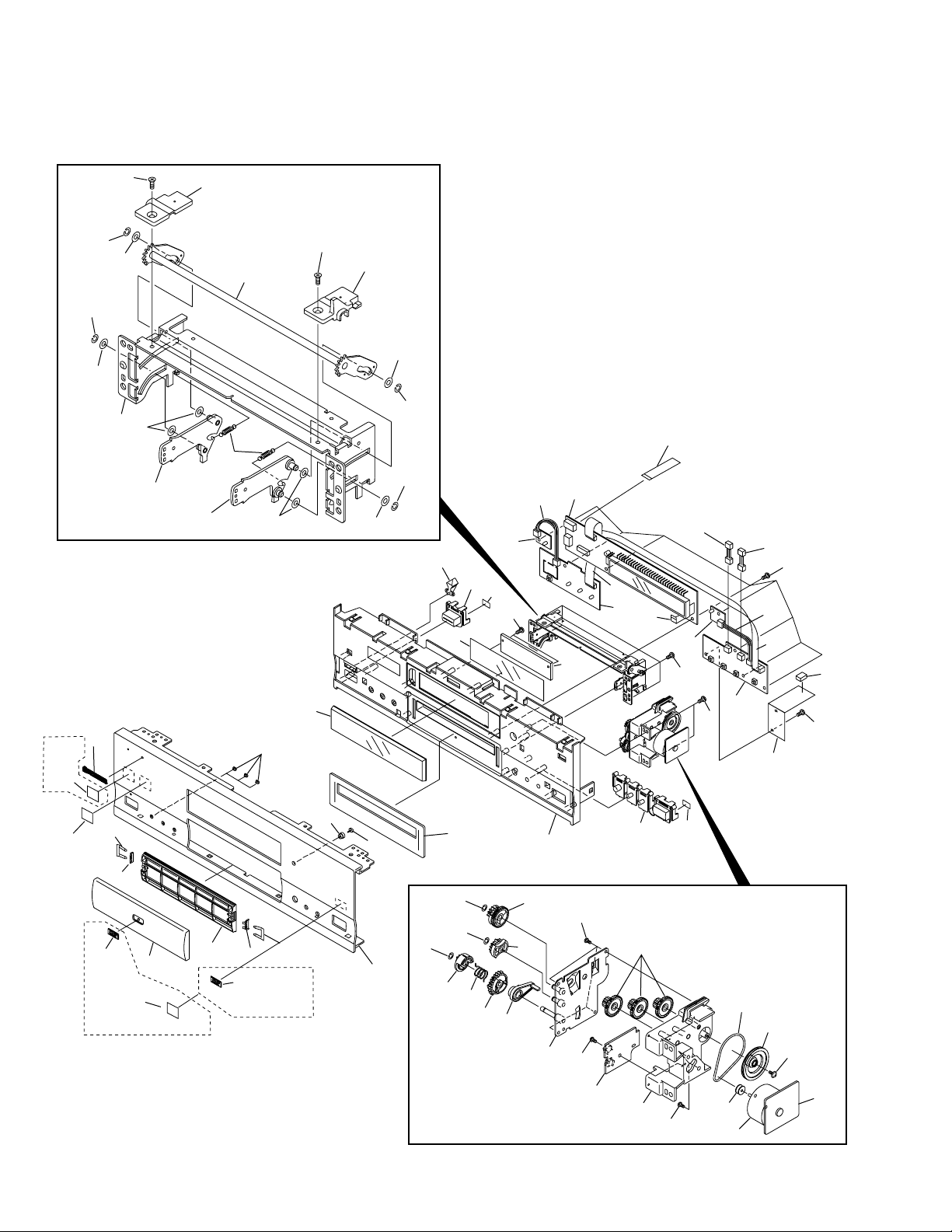
2.5 FRONT PANEL SECTION
DV-09
only
62
53
17
52
53
47
52
54
52
50
49 (1/2)
58
51
48
24
52
28
54
49 (2/2)
52
52
53
53
34
32
33
31
57
60
1
9
57
10
11
57
9
4
57
61
14
5
57
15
2
13
3
12
Guard
*
PCB
63
10
20
19
22
DV-S9 only
21
63
Note: *Guard PCB is incleded
in the PC board (FLAUD).
18
19
22
DV-09 only
20
25
26
23
56
44
27
56
56
43
42
41
45
46
29
40
55
55
39
59
31
35
38
37
55
6
8
30
7
36
Page 11
(1) FRONT PANEL SECTION PARTS LIST
Mark No. Description Part No.
1 FLKB Assy See Contrast table (2)
NSP 2 STBY Assy VWG1922
NSP 3 PWSB Assy VWG1916
NSP 4 LEDB Assy VWG1919
NSP 5 PLSB Assy VWG1913
NSP 6 DRMB Assy VWG1932
NSP 7 DRSB Assy VWG1930
8 DC Motor/0.75W(Door) PXM1010
9 Connector Assy PG03KK-E07
10 Connector Assy PG03KK4E07
11 Connector Assy PG03KK2E07
12 Flexible Cable (14P) VDA1661
(FLKB CN403-DVD MAIN CN503)
13 Flexible Cable (8P) VDA1668
(FLKB CN404-PWSB CN501)
NSP 14 Spacer VEC-244
15 VO Sheet FP VEC1992
16 • ••••
17 Name Plate See Contrast table (2)
18 Door Base See Contrast table (2)
19 Earth Plate VBK1074
20 Clip VBM1003
21 Door Aluminum See Contrast table (2)
22 DVD Plate See Contrast table (2)
23 Front Aluminum See Contrast table (2)
24 Lens PNW1257
25 DVD Ring VAK1006
26 DISP Lens PNW2113
27 Shield Cushion See Contrast table (2)
28 FL Lens See Contrast table (2)
29 Panel Base See Contrast table (2)
30 Main Key See Contrast table (2)
DV-09, DV-S9
Mark No. Description Part No.
31 Tape PNM1017
32 FL Filter See Contrast table (2)
33 PW Button See Contrast table (2)
34 LED Lens VNK4285
35 Motor Pulley PNW1634
36 Motor Holder VNL1796
37 Gear Pulley VNL1733
38 Belt (Rubber) PEB1288
39 Gear (C) VNL1047
40 Gear Base Assy VXA2365
41 Switch Arm VNL1797
42 Drive Gear C VNL1794
43 Door Spring A VBH1299
44 Drive Gear D VNL1795
45 Drive Gear B VNL1793
46 Drive Gear A VNL1792
47 Door Support VNE2140
48 Drive Arm Assy VXA2364
49 Drive Shaft Holder VNL1791
50 Door Arm L Assy VXA2362
51 Door Arm R Assy VXA2363
52 Washer WA32D080D025
53 Washer WT26D047D050
54 Screw CBZ26P060FMC
55 Screw Z39-019
56 Washer WT31D054D050
57 Screw BPZ30P080FCC
58 Door Spring B VBH1300
59 Screw BMZ26P040FMC
60 Flexible Cable (10P) VDA1660
(FLKB CN405-SYPS CN34)
61 Flexible Cable (8P) VDA1667
(FLKB CN402-PLSB CN523)
62 THX Badge See Contrast table (2)
NSP 63 DTS Label VRW1732
(2) CONTRAST TABLE
DV-09/KU/CA and DV-S9/L/TA are constructed the same except for the following :
.oNtraP
kraM.oNnoitpircseDdnalobmyS
1
71
81
12
22
32
72
82
92
03
23
33
26
yssABKLF
etalPemaN
esaBrooD
etalPDVD
sneLLF
esaBlenaP
yeKniaM
retliFLF
nottuBWP
egdaBXHT
munimulArooD
munimulAtnorF
noihsuCdleihS
90-VD
AC/UK/
0191GWV
4007MAA
0424KNV
5821HAV
6701MAV
3821HAV
0791CEV
8691CEV
6324KNV
8324KNV
6691CEV
1014KNV
3007MAA
9S-VD
AT/L/
1191GWV
1501MAV
9324KNV
4821HAV
7701MAV
2821HAV
9691CEV
7691CEV
5324KNV
7324KNV
5691CEV
9504KNV
desutoN
skrameR
11
Page 12
DV-09, DV-S9
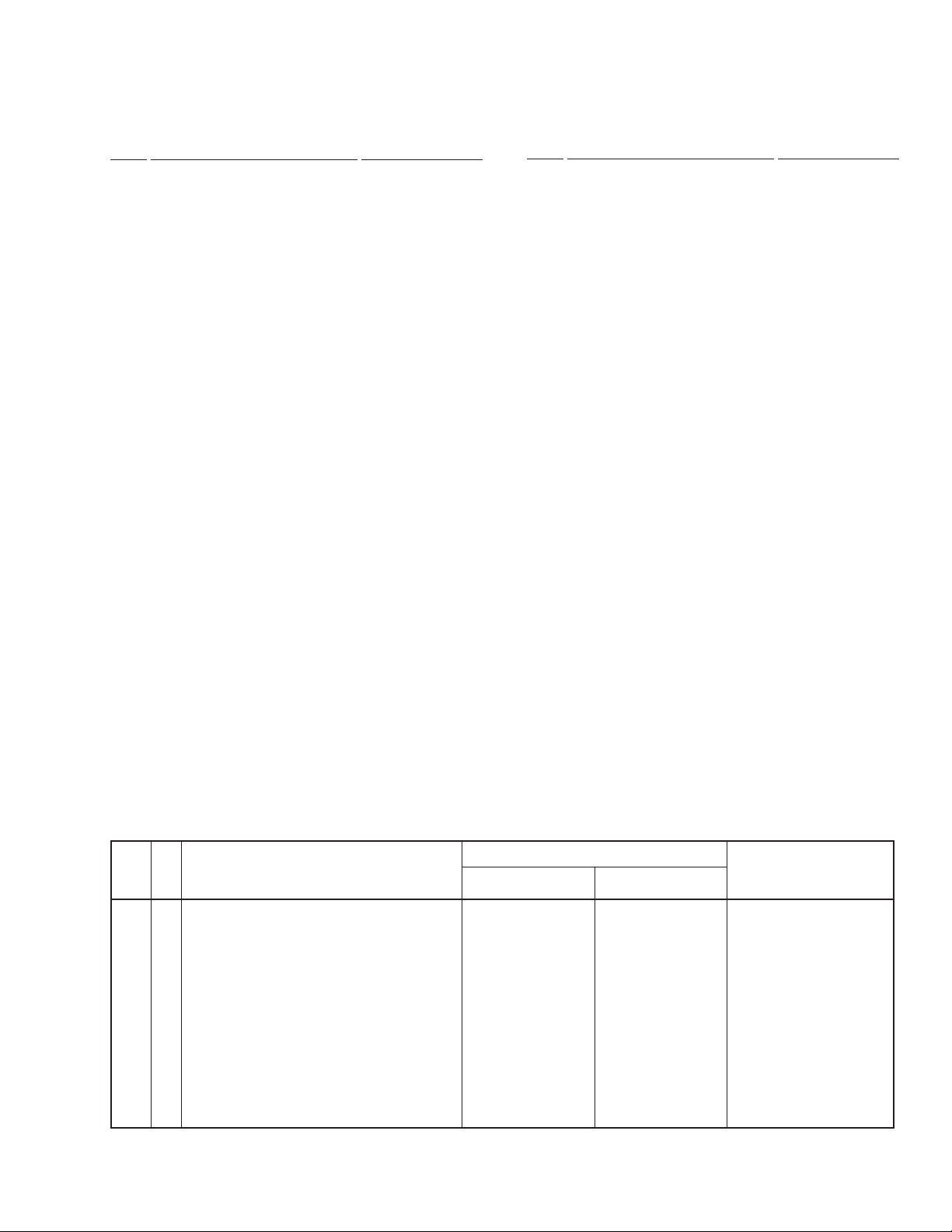
2.6 LOADING MECHANISM ASSY
• Top View • Bottom View
Refer to
"2.7 SERVO MECHANISM
ASSY".
5
1
3
4
20
6
2
18
10
17
9
13
7
8
16
15
LOADING MECHANISM ASSY PARTS LIST
•
Mark No. Description Part No.
1 Servo Mechanism Assy-S VXX2538
2 Screw DBA1006
3 Drive Cam VNL1736
4 Drive Gear VNL1735
5 Lock Plate VNL1737
6 Loading Base VNK4245
7 Rubber Belt VEB1260
NSP 9 LOSB Assy VWG1885
8 Gear Pulley VNL1733
10 Loading Gear VNL1734
11
12
Mark No. Description Part No.
11 Loading Motor Assy VXX2505
12 DC Motor PXM1027
13 Motor Pulley PNW1634
NSP 14 LOMB Assy VWG1886
15 Connector Assy (2P) PG02KK-E35
(LOMB CN401 – LOSB CN303)
16 Screw VBA1055
17 Screw Z39-019
18 Flexible Cable (8P) VDA1649
(LOSB CN302 – INSB CN202)
19 • • • • •
20 Stopper DNH2076
14
12
Page 13
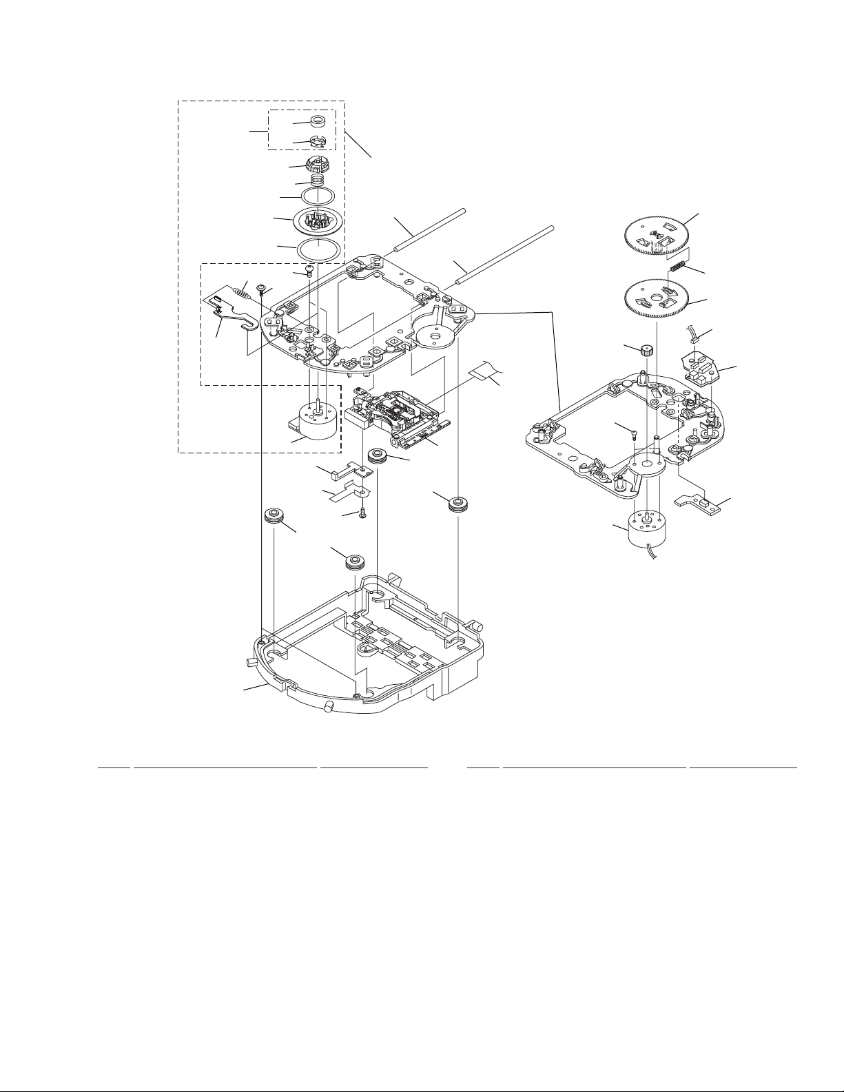
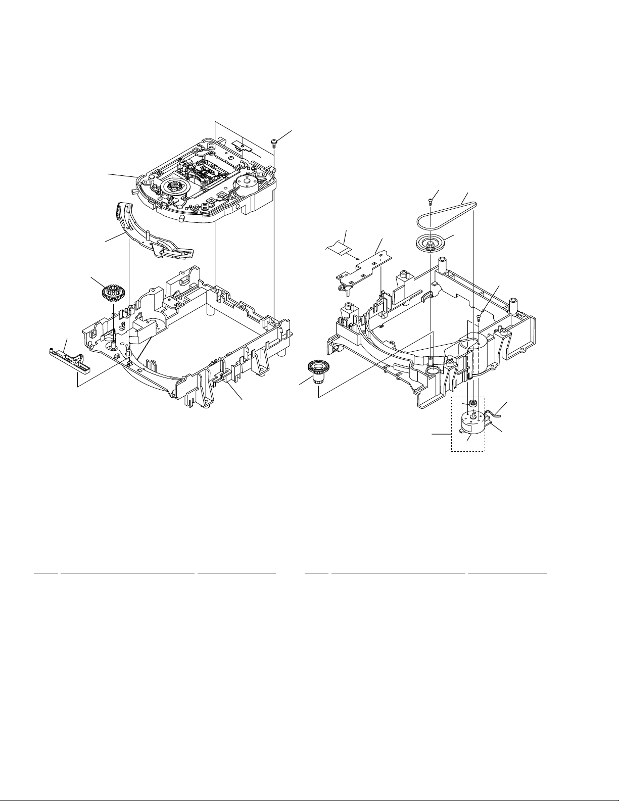
2.7 SERVO MECHANISM ASSY
• Top View
2
3
4
5
6
29
7
DV-09, DV-S9
• Bottom View
1
10
20
13
14
32
30
11
9
12
23
27
9
8
15
16
26
18
18
17
18
18
24
21
22
28
25
31
19
SERVO MECHANISM ASSY PARTS LIST
•
Mark No. Description Part No.
1 Spindle Motor Assy VXX2563
NSP 3 Magnet VYM1024
NSP 4 Magnet Holder VNE2070
NSP 7 Disc Table VNL1747
NSP 8 Motor VXM1071
NSP 17 Pickup Assy VWY1046
2 Magnet Holder Assy VXX2507
5 Centering Ring VNL1746
6 Centering Spring VBH1278
9 Screw JGZ17P028FMC
10 Sub Guide Bar VLL1489
11 Guide Bar VLL1488
12 Mechanism Base VNL1748
13 Hook VNL1770
14 Hook Spring VBH1291
15 Slider VNL1745
16 Hold Spring VNC1011
Mark No. Description Part No.
18 Floating Rubber DEB1315
19 Float Base VNL1732
20 Gear D VNL1766
21 Gear Spring VBH1279
22 Gear E VNL1767
23 Gear F VNL1768
24 Motor VXM1062
NSP 25 INSB Assy VWG1883
26 Screw PBZ20P050FMC
27 Flexible Cable (20P) VDA1680
(DVD MAIN CN102 – Pickup Assy)
28 Connector Assy (3P) VKP2150
(INSB CN201 – FGSB CN101)
NSP 29 Table Sheet DEC2040
30 Screw PBA1048
NSP 31 FGSB Assy VWG1884
NSP 32 Sheet VEC1959
13
Page 14
1
23
DV-09, DV-S9
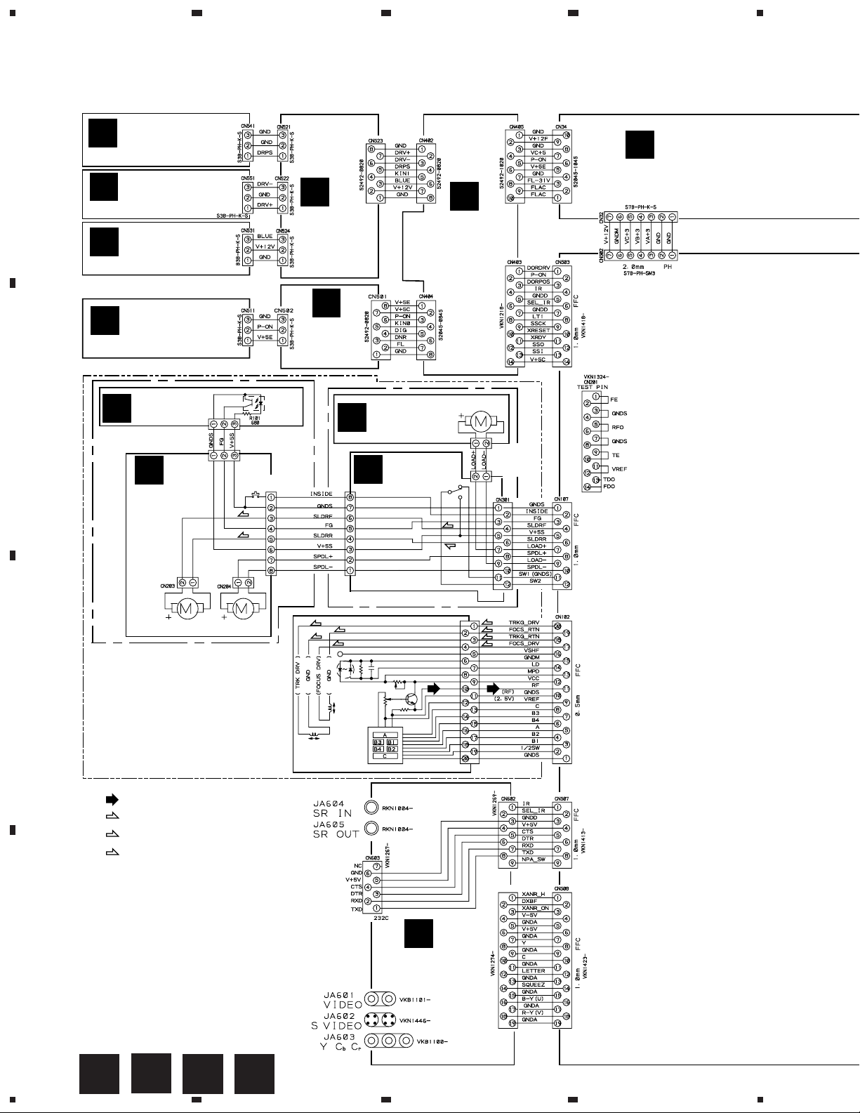
3. SCHEMATIC DIAGRAM
3.1 OVERALL CONNECTION DIAGRAM, LOMB, LOSB, INSB, FGSB, LSFB,
TRSA and TRSB ASSEMBLIES
DRSB
N
A
ASSY
(VWG1930)
DRMB
O
ASSY
(VWG1932)
LEDB
L
ASSY
(VWG1919)
J
PLSB ASSY
(VWG1913)
T
SYPS ASSY
(VWR1289)
I
FLKB ASSY
(VWG1910:DV-09)
(VWG1911:DV-S9)
pitch
4
STBY
M
ASSY
(VWG1922)
FGSB ASSY
D
B
(VWG1884)
CN201
B3B-PH-K-S
C
INSB ASSY
(VWG1883)
SMEB ASSY(VWM1797)
SLDR MOTOR
VXM1062
SPINDLE MOTOR
ASSY VXX2563
PC101
GP2S27(B)
CN101
B3B-PH-K-S
CN202
VKN1239
S201
(S)
(S)
LOADING
C
MECHANISM
K
PWSB
ASSY
(VWG1916)
LOMB ASSY
A
(VWG1886)
B
CN302
VKN1268
LOAB ASSY(VWM1798)
(T)
(F)
(T)
(F)
LOADING MOTOR
ASSY VXX2505
LOSB ASSY
(VWG1885)
S301
(S)
pitch
CN401
B2B-PH-K-S
CN303
B2B-PH-K-S
(S)
(T)
(F)
(T)
(F)
pitch
pitch
ASSY
(VWT1150)
PICKUP ASSY
(VWY1046)
: RF SIGNAL ROUTE
(F)
: FOCUS SERVO LOOP LINE
(T)
: TRACKING SERVO LOOP LINE
(S)
: SLIDER SERVO LOOP LINE
CN601
For
pitch
P
D
14
A
B
1234
C D
VOUT ASSY
(VWG1905)
pitch
Page 15
5
ANALOG VIDEO, AUDIO
ANALOG RF, MECHA,DSPA
SYSTEM CONT, MECHA CONT, DSPD,etc.
ANALOG VIDEO, AUDIO
AUDIO, (FLKB FL CONT)
FTS, (FLKB DOOR MOTOR)
LSI 11
AV1
DNR, ENCODER
pitch
H
H
1/4
H
DVD MAIN ASSY
(VWS1337)
4/4
678
DV-09, DV-S9
Note : When ordering service parts, be sure to refer to "EXPLODED
VIEWS and PARTS LIST" or "PCB PARTS LIST"
TRSB ASSY
G
(VWR1300)
A
POWER
TRANSFORMER(MAIN)
DV-S9 only
DV-09 only
3P INLET
ASSY
AC POWER CORD
(AC110V 50Hz)
AC POWER CORD
(AC 120V 60Hz)
E
LSFB ASSY
(VWR1293)
WHITE
BLACK
TRSA ASSY (VWR1298:DV-09)
F
(VWR1297:DV-S9)
B
pitch
pitch
POWER
TRANSFORMER
(AUDIO)
S
DIRB ASSY
(VWG1897)
DV-S9 only
R
AUDIO ASSY
(VWV1591:DV-09)
(VWV1590:DV-S9)
WHITE
RED
C
CN701
Q
DOUT ASSY
(VWG1902:DV-09)
pitch
5
(VWG1901:DV-S9)
6
DV-S9 only
FE
7
G
8
15
D
Page 16
1
DV-09, DV-S9
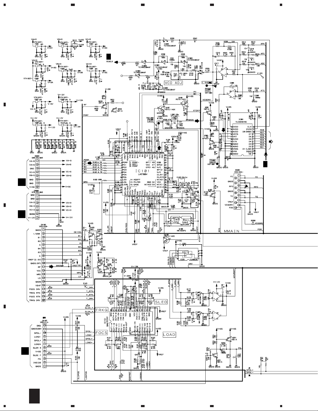
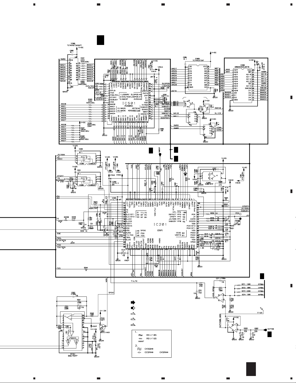
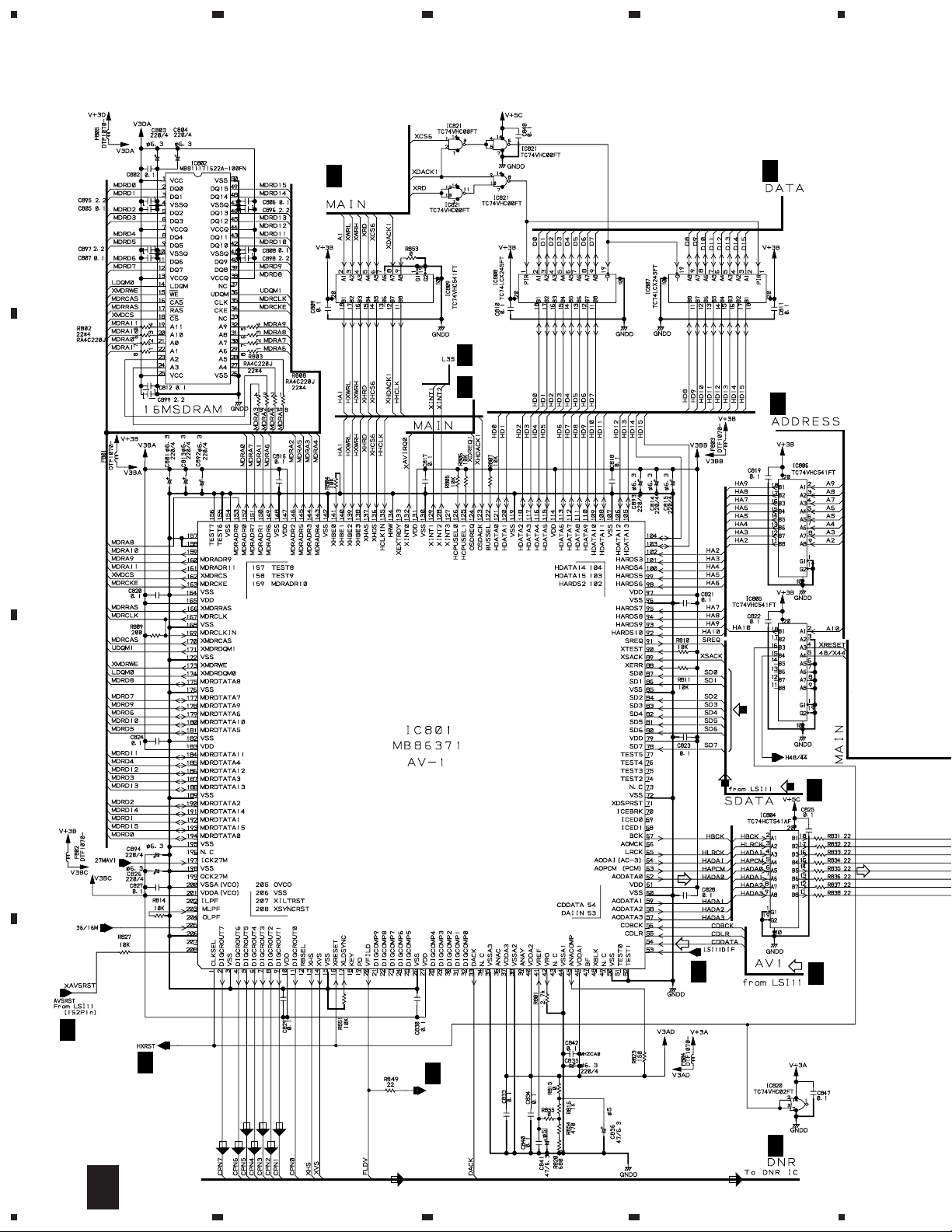
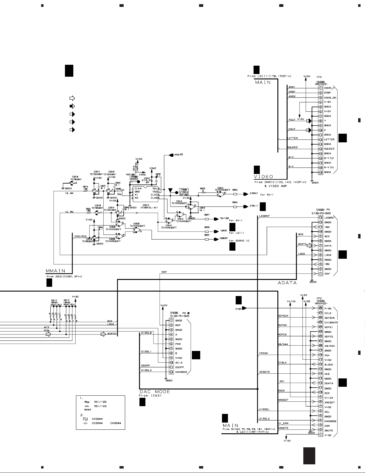
3.2 DVD MAIN ASSY(1/4)
23
(5/6)
4
A
B
PH CONNECTOR
GNDM
H
2/4
(1/6)
(2/6)
(3/6)
(4/6)
(6/6)
IC302(1/2)
NJM2100M
IC302(2/2)
NJM2100M
(ROM)
H
(ROM)
2/4
CN33
T
PH CONNECTOR
CN32
T
(T)
C
(T)
(S)
PICKUP ASSY
(T)
(F)
(T)
(F)
CN301
B
(T)
(S)
(S)
(S)
(S)
D
(T)
(S)
(F)
(F)
(F)
(S)
IC171(2/2)
BA10393F
IC171(1/2)
BA10393F
16
(F)
H
1/4
1234
Page 17
5
678
DV-09, DV-S9
H
(T)
DVD MAIN ASSY
1/4
(VWS1337)
A
IC504
TC74VHC20FT
IC505(1/2)
TC74VHC139FT
IC505(2/2)
TC74VHC139FT
FG,BMAD0-BMAD7,XMRD,XMWR,XMIRQ2,
H
H
3/4
2/4
XLICS.ASTB,DORPOS,XRESET,C2F,ROMXA,
ROMCK,LRSY,SBCK,SFSY,PW,SBSY,DOUT
DVD/XCD
H
3/4
(ROM)
B
(T)
(F)
(F)
LC78650NE
(S)
(F)
(T)
H
2/4
: RF SIGNAL ROUTE
(ROM)
: ROM DATA SIGNAL ROUTE
(F)
: FOCUS SERVO LOOP LINE
(T)
: TRACKING SERVO LOOP LINE
(S)
: SLIDER SERVO LOOP LINE
RESISTORS
Rank F
CAPACITORS
or
IC271(2/2)
NJM2100M
IC271(1/2)
NJM2100M
H
2/4
C
D
H
1/4
5
6
7
8
17
Page 18
1
DV-09, DV-S9
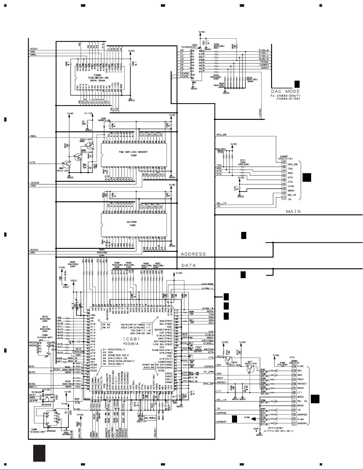
3.3 DVD MAIN ASSY(2/4)
A
23
VYW1558
4
H
3/4
B
P
CN602
PDK026
H
3/4
ADDRESS
A0–A10
H
3/4
DATA
D0–D15
C
(1/2)
DORPOS,XRESET,C2F
H
1/4
XWRL,XWRH,XAMUTE,XDREQ1,SSI,SSCK,
H
3/4
DI-ERR,48/X44,HIBSEL,DIBLK,XAVIRQO
SSO,SSCK,I2CSSEL
H
4/4
I
D
H
3/4
(2/2)
18
H
2/4
1234
CN403
Page 19
5
678
DV-09, DV-S9
RESISTORS
Rank F
CAPACITORS
H
SDATA
(ROM)
3/4
(ROM)
H
DVD MAIN ASSY
2/4
(VWS1337)
or
: AUDIO SIGNAL ROUTE
(ROM)
: ROM DATA SIGNAL ROUTE
H
3/4
H
3/4
XTOP
From IC801
H
3/4
H
(ROM)
H
1/4
(ROM)
A
1/4
B
H
1/4
C
H
1/4
H
3/4
H
3/4
(ROM)
H
3/4
H
3/4
H
1/4
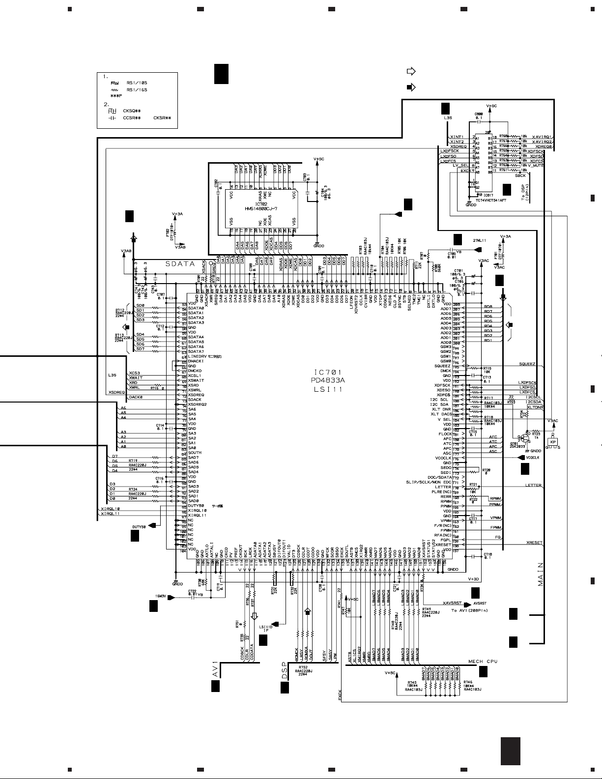
XDFSCK,XDFSO,XDFCS,
SQUEEZ,LETTER
I2CSCL,I2CSDA,XLTDNR
H
3/4
H
4/4
H
1/4
D
H
5
6
7
2/4
8
19
Page 20
1
DV-09, DV-S9
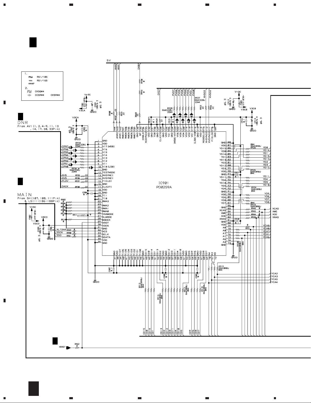
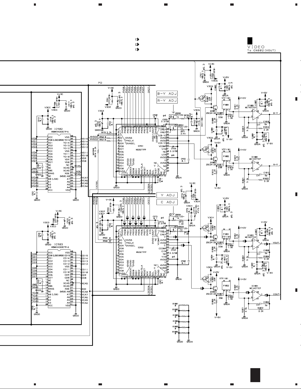
3.4 DVD MAIN ASSY(3/4)
23
(1/4)
4
A
H 2/4
XWRH,XWRL
(4/4)
(2/4)
H 2/4
(3/4)
H 2/4
H 2/4
H 2/4
B
(ROM)
C
(ROM)
H 2/4
(ROM)
H 2/4
H 2/4
H 2/4
D
H 4/4
H 2/4
XTOP
To IC701
(1/4)
20
H 4/4
H
3/4
1234
Page 21
5
DVD MAIN ASSY
3/4
H
(VWS1337)
: AUDIO SIGNAL ROUTE
(ROM)
: ROM DATA SIGNAL ROUTE
: VIDEO SIGNAL ROUTE
(Y)
: Y SIGNAL ROUTE
(C)
: C SIGNAL ROUTE
678
DV-09, DV-S9
A
H 2/4
(Y)
(C)
CN601
P
H 1/4
(2/3)
(3/3)
(1/3)
(2/4)
(3/4)
(4/4)
(2/4)
(4/4)
(1/4)
VTL1074
VTL1075
VTL1075
(3/4)
VTL1075
VTL1074
H 2/4
H 1/4
H 2/4
H 4/4
B
H 2/4
CN801
S
C
RESISTORS
CAPACITORS
5
Rank F
CN701
Q
CN802
S
H 2/4
D
or
6
H 2/4
H
3/4
7
8
21
Page 22
1
DV-09, DV-S9
3.5 DVD MAIN ASSY(4/4)
DVD MAIN ASSY
4/4
H
A
(VWS1337)
23
4
H
B
H
XLTDNR,SSCK,SSO,
I2CSEL,I2CSDA,I2CSCL
RESISTORS
CAPACITORS
3/4
2/4
MUTEV
Rank F
or
MUTEV
C
YCA6
YCA1
YCA7
YCA0
YCA8
XRA5
XOE
XWE
YCA2
YCA3
YCA5
YCA4
H
3/4
D
22
H
4/4
1234
XCAS
Page 23
5
678
DV-09, DV-S9
: VIDEO SIGNAL ROUTE
(Y)
: Y SIGNAL ROUTE
(C)
: C SIGNAL ROUTE
MUTEV
Q1006
PDTA143EK
H
(1/2)
3/4
A
Q1005
Q1055:
PDTA143EK
Q1055
(Y) (Y)
(C)
Q1056
PDTA143EK
(C)
Q1005:
PDTA143EK
(Y)
(C)
(1/2)
(2/2)
(2/2)
(Y)
B
C
(C)
D
H
5
6
7
4/4
8
23
Page 24
1
23
DV-09, DV-S9
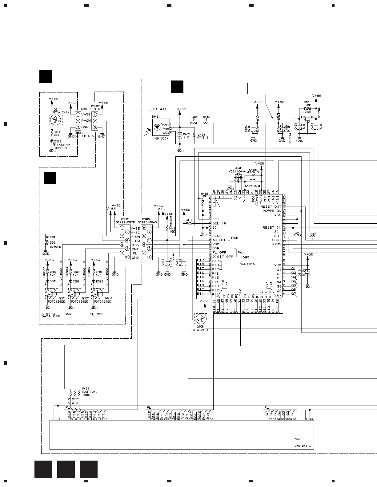
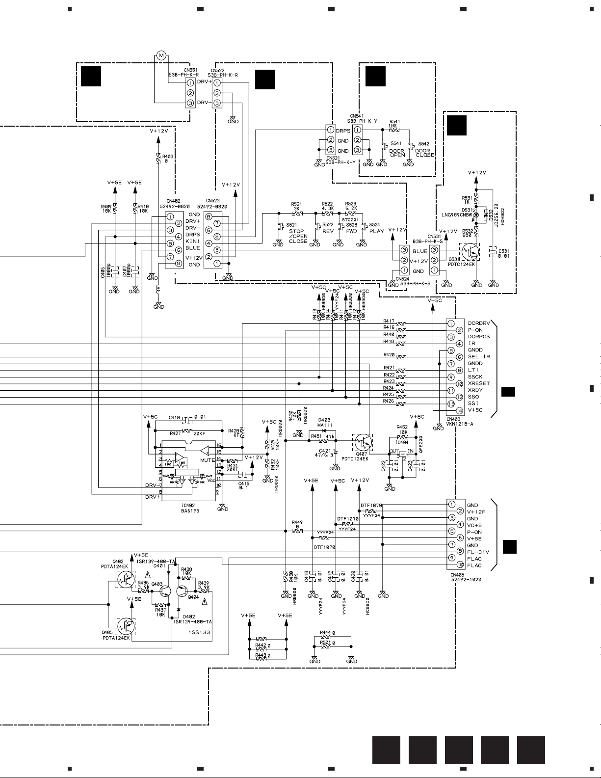
3.6 FLKB, PLSB, PWSB, LEDB, STBY, DRSB and DRMB ASSEMBLIES
A
STBY ASSY
M
(VWG1922)
YELLOW
PWSB ASSY
B
K
(VWG1916)
FLKB ASSY
I
(VWG1910:DV-09)
(VWG1911:DV-S9)
5MHz
R408:
2K (DV-09)
12K (DV-S9)
R405
12k
R406
2k
R407:
12 K (DV-09)
4.7K (DV-S9)
R407
R408
4
IC401 :
RESET IC
PST994C
TEST PIN
FOR CHECKER
220k
RSG1030
MODE CONTROL IC
RED RED RED
C
D
FL TUBE
24
I K M
1234
Page 25
5
678
DV-09, DV-S9
DC MOTOR
/0.75W(DOOR)
PXM1010
O
DRMB ASSY
(VWG1932)
L401
VTH1024
GND
J
PLSB ASSY
(VWG1913)
S521-S524 :
RSG1030
N
DRSB ASSY
(VWG1930)
S541, S542 :
DSG1017
33
33
33
33
33
33
33
33
33
33
33
A
L
LEDB ASSY
(VWG1919)
B
CN503
2/4
H
2SD1858X
LEVEL SHIFT
2SD1858X
30
DTF1070
F404
PWSB ASSY
S501:POWER
STANDBY/ON
F401
F402
PLSB ASSY
S521: §
S522: 4
S523: ¢
S524: 6
PST994C
C
F403
CN34
T
D
ONLJI
5
6
7
8
25
Page 26

1
DV-09, DV-S9
3.7 VOUT ASSY
A
23
VOUT ASSY (VWG1905)
P
4
1SS355
SR IN
CN507
2/4
H
B
(C) (C) (C)
SR OUT
1SS355
1SS355
(C)
C
(Y) (Y) (Y) (Y)
CN508
(C)
(C) (C)
(Y)
IC602 (1/2)
3/4
H
D
26
P
1234
Page 27

5
678
DV-09, DV-S9
: VIDEO SIGNAL ROUTE
(Y)
(C)
IC604 (2/2)
: Y SIGNAL ROUTE
: C SIGNAL ROUTE
VIDEO OUT
A
(C)
(Y)
(C)
(Y)
IC602 (2/2)
(C)
(C)
(Y) (Y)
IC603 (1/2)
IC603 (2/2)
IC607 (1/2)
IC604 (1/2)
(Y)
(C) (C)
(Y)
(Y)
IC605 (1/2)
IC606 (2/2)
IC605 (2/2)
(Y) (Y)
(C) (C)
IC606 (1/2)
S OUT
B
(Y) (Y)
(C)
(C)
C
Y OUT
Cb OUT
Cr OUT
IC607 (2/2)
IC606 (1/2)
D
P
5
6
7
8
27
Page 28

1
23
DV-09, DV-S9
3.8 DOUT and AUDIO ASSEMBLIES
F101
A
CN811
S
DTF1070
TP1
F111 DTF1070
AUDIO ASSY
R
(VWV1591:DV-09)
(VWV1590:DV-S9)
TC74HC164AF
4
TC74HC163AF
B
DV-S9
only
CN812
S
C
CN506
3/4
R147
R149
10K
DV-09
only
R148
15p
8p
10K
470560
12p
27p
TC74HC153AF
R799
DV-09 only
F143 / R143
F133 / R133
DV-09: F143 DTF1069
DV-S9: R143 100
DV-09: F133 DTF1069
DV-S9: R133 100
R798
DV-09
only
TC74HC164AF
TC74HC163AF
TC74HC164AF
H
TC74HC153AF
TC74HC153AF
DV-09
only
D
DV-S9 only
28
Q R
1234
Page 29

5
678
DV-09, DV-S9
: AUDIO SIGNAL ROUTE
R314:
2.2K (DV-09)
2.4K (DV-S9)
C316
390p
C393
2.2µF
C394
2.2µF
C346
390p
CAUTION : FOR CONTINUED PROTECTION AGAINST RISK
OF FIRE, REPLACE ONLY WITH SAME TYPE NO. ICP-N38
ROHM CO.,LTD. FOR IC352 AND IC372.
IC302, IC303, IC332, IC333
NJM5532DD
R314:
2.2K (DV-09)
2.4K (DV-S9)
CAUTION : FOR CONTINUED PROTECTION AGAINST RISK
OF FIRE, REPLACE ONLY WITH SAME TYPE NO. ICP-N25
ROHM CO.,LTD. FOR IC361 AND IC381.
A
B
CN12
F
PDTC124EK
PDTC124EK
2SB1237X
PDTC124EK
PDTA124EK
PDTC124EK
2SB1237X
ICP-N38
ICP-N38
Q371, Q373
2SA1037K
2SC2412K
2SC3179
NJM4580L
NJM4580L
2SA1262
D351, D352, D371, D372
UDZS5.6B
ICP-N25
C391
2.2µF
(YF)
C392
2.2µF
(YF)
IC771 TC7WU04F
Q361 : 2SC2412K
Q362 : 2SC3179
ICP-N25
Q381 : 2SA1037K
Q382 : 2SA1262
NJM4580L
NJM4580L
D361, D381
UDZ3.6B
Q
DOUT ASSY
(VWG1902:DV-09)
(VWG1901:DV-S9)
C
D
5
6
7
8
RQ
29
Page 30

DV-09, DV-S9
3.9 DIRB ASSY
A
CN505
H 3/4
B
1
23
DIRB ASSY (VWG1897)
S
4
(DV-S9 only)
CN504
H 3/4
3/44/4
C
1/4
2/4
D
30
S
1234
Page 31

5
678
DV-09, DV-S9
3/4
3/4
2/4
4/4
2/4
4/4
1/4
1/4
1/2
: AUDIO SIGNAL ROUTE
A
CN101
R
B
3/3
1/3
2/2
2/3
1/2
1/4
4/4
3/4
2/4
2/2
C
CN111
R
D
S
5
6
7
8
31
Page 32

1
DV-09, DV-S9
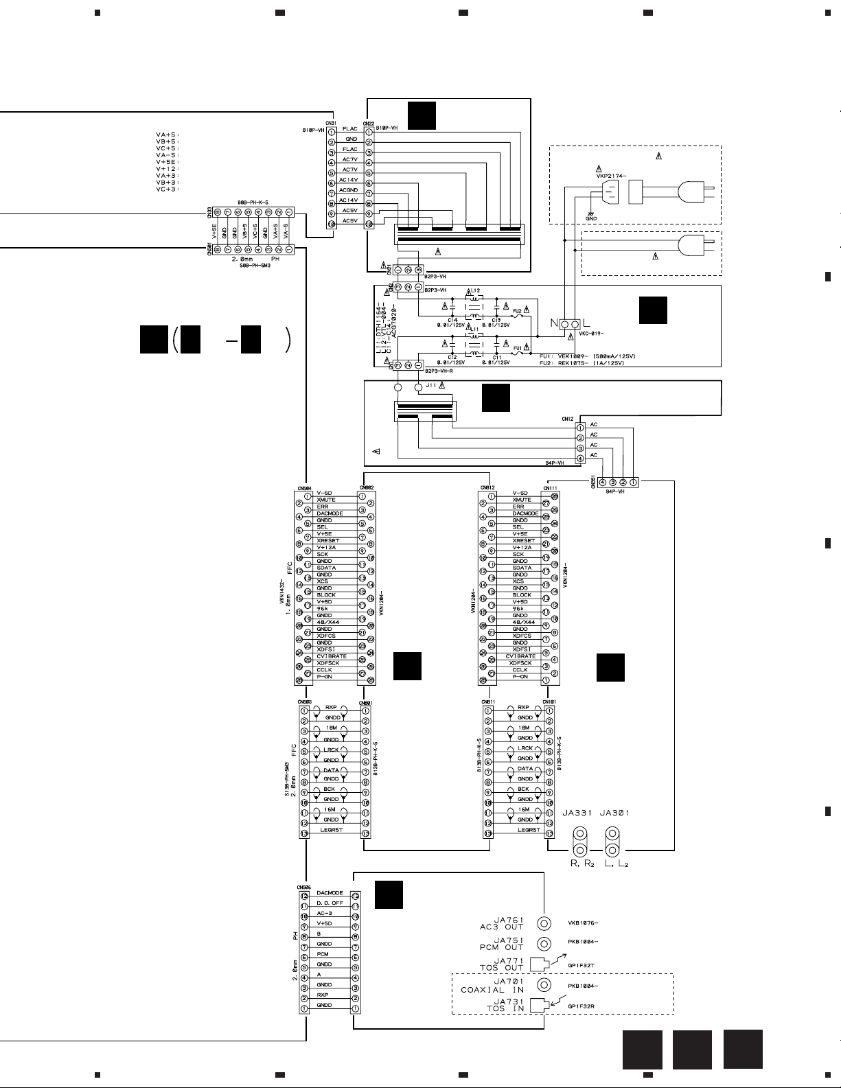
3.10 SYPS ASSY
NOTE FOR FUSE REPLACEMENT
CAUTION :
AGAINST RISK OF FIRE,REPLACE
WITH SAME TYPE AND RATINGS
A
ONLY.
FOR CONTINUED PROTECTION
23
SYPS ASSY (VWR1289)
T
CAUTION : FOR CONTINUED PROTECTION AGAINST
RISK OF FIRE, REPLACE ONLY WITH SAME TYPE NO.
491.750, MFD BY LITTELFUSE INC. FOR IC101.
CAUTION : FOR CONTINUED PROTECTION AGAINST
RISK OF FIRE, REPLACE ONLY WITH SAME TYPE NO.
491.400, MFD BY LITTELFUSE INC. FOR IC102, IC201
AND IC203.
4
750mA
1SS3551SS355
CAUTION : FOR CONTINUED PROTECTION AGAINST
RISK OF FIRE, REPLACE ONLY WITH SAME TYPE NO.
4911.25, MFD BY LITTELFUSE INC. FOR IC202.
400mA
B
1.25A
400mA
CAUTION : FOR CONTINUED PROTECTION AGAINST
RISK OF FIRE, REPLACE ONLY WITH SAME TYPE NO.
491.250, MFD BY LITTELFUSE INC. FOR IC303.
250mA
CN22
G
800mA
C
800mA
CAUTION : FOR CONTINUED PROTECTION
AGAINST RISK OF FIRE, REPLACE ONLY
WITH SAME TYPE NO. 491.800, MFD BY
LITTELFUSE INC. FOR IC301 AND IC302.
D
200mA
200mA
CAUTION : FOR CONTINUED PROTECTION AGAINST RISK OF FIRE,
32
T
REPLACE ONLY WITH SAME TYPE NO. 491.200, MFD BY LITTELFUSE
INC. FOR IC314 AND IC324.
125mA
CAUTION : FOR CONTINUED PROTECTION AGAINST RISK OF FIRE,
REPLACE ONLY WITH SAME TYPE NO. 491.125, MFD BY LITTELFUSE
INC. FOR IC304.
1SS355
CN405
I
1234
Page 33

5
CAUTION : FOR CONTINUED PROTECTION AGAINST
RISK OF FIRE, REPLACE ONLY WITH SAME TYPE NO.
491.500, MFD BY LITTELFUSE INC. FOR IC103.
678
DV-09, DV-S9
A
1SS355
1SS355
500mA
400mA
1SS3551SS355
120
1SS355
1SS355
1SS355
1SS355
R417
0
470
IC402 (1/3)
1K
IC402 (2/3)
IC402 (3/3)
CN501
1/4
H
B
C
5
IC401 (2/2)
IC401 (1/2)
CN502
1/4
H
D
6
7
8
T
33
Page 34

1
23
DV-09, DV-S9
4. PCB CONNECTION DIAGRAM
NOTE FOR PCB DIAGRAMS :
1. Part numbers in PCB diagrams match those in the schematic
A
diagrams.
2. A comparison between the main parts of PCB and schematic
diagrams is shown below.
Symbol In PCB
Diagrams
BCE
BCE
D
Symbol In Schematic
Diagrams
BCEBCE
BCE
DGGSS
BCE
DGS
Part Name
Transistor
Transistor
with resistor
Field effect
transistor
Resistor array
4
3. The parts mounted on this PCB include all necessary parts for
several destinations.
For further information for respective destinations, be sure to
check with the schematic diagram.
4. View point of PCB diagrams.
Connector
Capacitor
SIDE A
P.C.Board
Chip Part
SIDE B
B
3-terminal
regulator
4.1 LOMB, LOSB, INSB and FGSB ASSEMBLIES
CN107
LOSB ASSY
B
H
C
C
SIDE A
SLDR
MOTOR
(VNP1628-A)
INSB ASSY
(VNP1627-B)
LOMB ASSY
A
FGSB ASSY
D
SPINDLE MOTOR
ASSY
INSB ASSY
C
FGSB ASSY
D
SIDE B
D
(VNP1627-B)
34
A
B C D
1234
Page 35

1
234
4.2 LSFB, TRSA and TRSB ASSEMBLIES
TRSB
G
ASSY
CN31
T
DV-09, DV-S9
A
B
LSFB ASSY
E
POWER TRANSFORMER (MAIN)
POWER TRANSFORMER (AUDIO)
(VNP1637-C)
3P
INLET
ASSY
C
(VNP1636-C)
1
F
TRSA
ASSY
CN351
R
D
SIDE A
(VNP1637-C)
E F G
2
3
4
35
Page 36

1
S
C
DV-09, DVS9
4.3 DVD MAIN ASSY
A
H
Q
CN701
B
23
DVD MAIN ASSY
CN801
S
CN802
S
4
DVD
CARRIAGE A
P
CN602
C
P
CN601
D
VR954 VR953 VR952 VR951
VR801
Q801
Q802
IC902
IC901
IC824
IC904
IC801
VC301
Q901
IC303
IC903
IC806 IC807
IC205
IC302
IC271
I
SIDE A
36
H
1234
Page 37

5
678
DV-09, DV-S9
•This PCB is a four-layered board.
Middle layer is mainly connected to Vcc and GND.
RIAGE ASSY
CN301
B
A
T
CN32
B
T
CN33
IC205
IC302
IC271
IC204
IC202
Q301
IC701
I
C
CN403
IC203
IC171
Q102
IC751 IC821
IC151
IC161
IC206
IC601
Q291
(VNP1635-B)
IC506 IC251
IC501
D
SIDE A
H
5
6
7
8
37
Page 38

DV-09, DVS9
7
A
B
1
DVD MAIN ASSY
H
23
4
C
D
38
H
1234
IC652 Q772
IC605
Q771
Q601–Q603
IC602
IC191
IC503
IC502
IC603 IC604
Q261
IC504
IC505
SIDE B
Q109 Q108
IC201
IC101 Q455
IC301
Q701
IC702 IC817
Q103–Q10
Page 39

5
678
DV-09, DV-S9
•This PCB is a four-layered board.
Middle layer is mainly connected to Vcc and GND.
A
B
Q103–Q107
01
IC817
IC808 IC804IC809 IC651
5
IC802
IC811
IC818 IC810
IC951 Q1005 Q1055 Q1056IC952
IC820 IC813 IC814 IC819
Q1006 Q1001Q1002 Q1051 Q1052
IC805 IC1001 IC1051
SIDE B
6
C
(VNP1635-B)
H
7
8
39
D
Page 40

1
23
DV-09, DV-S9
4.4 FLKB, PLSB, PWSB, LEDB, STBY, DRSB and DRMB ASSEMBLIES
I
PLSB
A
FLKB
ASSY
T
CN34
J
ASSY
4
IC402
Q404
B
LEDB
ASSY
DRMB ASSY
O
PWSB ASSY
K
L
IC401
C
DRSB ASSY
N
(VNP1637-C)
H
STBY ASSY
CN503
IC404
D
M
SIDE A
40
I J K L M N O
1234
Page 41

1
234
DV-09, DV-S9
PLSB
J
ASSY
DRMB ASSY
O
DRSB ASSY
N
FLKB
I
ASSY
L
LEDB
ASSY
A
Q406
B
Q402
Q405
PWSB ASSY
K
Q503
Q502
Q501
Q504
STBY ASSY
M
IC403
C
(VNP1637-C)
Q407
D
SIDE B
I J K L M N O
1
2
3
4
41
Page 42

1
23
DV-09, DVS9
4.5 VOUT, DOUT and AUDIO ASSEMBLIES
4
CN508
H
A
B
VOUT ASSY
P
AUDIO ASSY
R
IC601
H
S
CN507
CN811
CN812
S
(VNP1636-C)
C
F
CN12
D
VC131
IC371 IC381 IC372
IC351
IC361 IC352
Q372
Q382
Q362
Q352 IC101
IC111IC151 Q153
SIDE A
42
P R
1234
Page 43

5
DOUT ASSY
Q
678
DV-09, DV-S9
CN506
H
A
B
(VNP1636-C)
Q732Q734
C131
IC111
C
D
(VNP1637-C)
IC301
IC331
IC302
IC332
IC303
IC333
SIDE A
Q R
5
6
7
8
43
Page 44

DV-09, DVS9
Q
A
B
1
DOUT ASSY
(VNP1636-C)
23
IC751 IC733 IC761 IC741
IC771
IC721
IC711Q731
4
Q733
AUDIO ASSY
R
C
D
(VNP1637-C)
IC191
IC181
IC182
IC222 IC211 IC131
IC202 IC221
IC141
44
Q R
IC201
IC171
SIDE B
1234
Page 45

5
VOUT ASSY
P
(VNP1636-C)
678
DV-09, DV-S9
A
B
Q616 IC604 Q608
IC602
Q613
IC603Q601–Q607
Q609–Q612
IC605 IC607 IC606
Q614 Q615
IC211 IC131
IC141
IC121 Q151 Q375 Q381
Q361 Q373Q351
SIDE B
5
6
Q371
Q374
Q376
C
D
P R
7
8
45
Page 46

1
DV-09, DV-S9
4.6 SYPS ASSY
A
G
CN22
SYPS ASSY
T
23
4
IC324
IC314
IC304
B
C
IC303
Q303
Q304
Q302
Q301
IC201
Q201
IC302
IC301
Q103
Q312
IC103
Q202
Q102
IC202
IC102
IC101
Q203
IC203
Q101
H
CN501
IC312
D
(VNP1636-C)
46
CN405
I
T
1234
SIDE A
CN502
H
IC322
Page 47

1
SYPS ASSY
T
234
DV-09, DV-S9
A
Q313
Q321
Q311
Q211
Q123
Q221
Q113
Q122
Q212
Q112
Q222
Q121
Q213
Q111
IC401
Q223
B
C
IC402
D
(VNP1636-C)
SIDE B
1
2
3
T
4
47
Page 48

DV-09, DV-S9
4.7 DIRB ASSY
A
B
1
S
23
DIRB ASSY
4
R
CN101
R
CN111
SIDE A
H
CN505
(VNP1636-C)
DIRB ASSY
S
C
H
CN504
IC903
IC901
IC811
Q911
IC902
IC831
IC835
IC905
IC904
IC861
IC906
SIDE B
IC841
IC821
D
(VNP1636-C)
48
S
1234
Page 49

5. PCB PARTS LIST
DV-09, DV-S9
NOTES:
Parts marked by "NSP" are generally unavailable because they are not in our Master Spare Parts List.
The mark found on some component parts indicates the importance of the safety factor of the part.
Therefore, when replacing, be sure to use parts of identical designation.
When ordering resistors, first convert resistance values into code form as shown in the following examples.
Ex.1 When there are 2 effective digits (any digit apart from 0), such as 560 ohm and 47k ohm (tolerance is shown by J=5%,
and K=10%).
560
47k
0.5
1
56 x 10
47 x 103
R50
1R0
1
561
473
Ex.2 When there are 3 effective digits (such as in high precision metal film resistors).
5.62k RN1/4PC F562 x 10
1
5621
5.1 LIST OF WHOLE PCB ASSEMBLIES
kraMnoitpircseDdnalobmyS
PSN
PSN
PSN
PSN
PSN
PSN
YSSABAOL
YSSABMOL
YSSABSOL
YSSABEMS
YSSABSNI
YSSABSGF
YSSANIAMDVD
RD1/4PU J
RD1/4PU J
RN2H K
RS1P K
561
473
R50
1R0
5621
.oNtraP
90-VD
AC/UK/
8971MWV
6881GWV
5881GWV
7971MWV
3881GWV
4881GWV
7331SWV
9S-VD
AT/L/
8971MWV
6881GWV
5881GWV
7971MWV
3881GWV
4881GWV
7331SWV
skrameR
PSN
PSN
PSN
PSN
PSN
PSN
PSN
PSN
PSN
PSN
PSN
YSSATUOYS
YSSABRID
YSSATUOD
YSSATUOV
YSSASPYS
YSSABFSL
YSSADUALF
YSSABKLF
YSSABSLP
YSSABSWP
YSSABDEL
YSSAYBTS
YSSABSRD
YSSABMRD
YSSAASRT
YSSABSRT
YSSAOIDUA
2181MWV
desutoN
2091GWV
5091GWV
9821RWV
3921RWV
6181MWV
0191GWV
3191GWV
6191GWV
9191SWV
2291GWV
0391GWV
2391GWV
8921RWV
0031RWV
1951VWV
TRSA ASSY
VWR1298 and VWR1297 are constructed the same except for the following :
kraMnoitpircseDdnalobmyS
11J6812PKV5612PKV
8921RWV7921RWV
.oNtraP
FLKB ASSY
VWG1910 and VWG1911 are constructed the same except for the following :
1181MWV
7981GWV
1091GWV
5091GWV
9821RWV
3921RWV
7181MWV
1191GWV
3191GWV
6191GWV
9191SWV
2291GWV
0391GWV
2391GWV
7921RWV
0031RWV
0951VWV
skrameR
kraMnoitpircseDdnalobmyS
704R
804R
.oNtraP
0191GWV1191GWV
J321S01/1SR
J202S01/1SR
skrameR
J274S01/1SR
J321S01/1SR
49
Page 50

DV-09, DV-S9
AUDIO ASSY
VWV1591 and VWV1590 are constructed the same except for the following :
kraMnoitpircseDdnalobmyS
1951VWV0951VWV
)DAEBPIHC(111F,101F
)DAEBPIHC(341F,331F
desutoN
9601FTD
.oNtraP
skrameR
0701FTD
desutoN
0022(173C,153C µ )V05/F
022(683C,673C,663C,653C µ )V05/F
293C,193C
493C,393C
111R
341R,331R
941R-741R
443R,413R
)KCAJNIPP2(103AJ
)KCAJNIPP2(133AJ
0611HCV
1611HCV
52Z522FYSKC
61Z522FYQSKC
J0R0S01/1SR
desutoN
J301S01/1SR
J222MP2/1RDR
5901BKV
6901BKV
DOUT ASSY
VWG1902 and VWG1901 are constructed the same except for the following :
kraMnoitpircseDdnalobmyS
117CI
337CI
117C
217C
317C
417C
2091GWV1091GWV
147CI,127CI
337Q,137Q
437Q,237Q
)DAEBPIHC(147F,437F,137F,127F,117F
desutoN
desutoN
desutoN
desutoN
desutoN
desutoN
desutoN
desutoN
desutoN
desutoN
.oNtraP
5211HCV
0411HCV
desutoN
desutoN
desutoN
J101S01/1SR
desutoN
J242MP2/1RDR
3011BKV
4011BKV
skrameR
F40UW7CT
FA351CH47CT
F80W7CT
KE421CTDP
X7321BS2
0701FTD
05Z301FYQSKC
01M074ABEC
05J101HCQSCC
J022HCQSCC05
50
147C,337C,137C,127C,517C
001(287C,187C,537C µ )V01/F
117R
447R,347R,327R,217R
317R
417R
227R,617R,517R
137R
487R-187R
997R-797R
)KCAJNIPP1(107AJ
)TUPTUOLACITPO(137AJ
desutoN
desutoN
desutoN
desutoN
desutoN
desutoN
desutoN
desutoN
desutoN
J0R0S01/1SR
desutoN
desutoN
2Z401FYQSKC5
0011HCV
J057S01/1SR
J0R0S01/1SR
J374S01/1SR
J222S01/1SR
J101S01/1SR
J322S01/1SR
J274S01/1SR
desutoN
4001BKP
R23F1PG
Page 51

5.2 PARTS LIST FOR DV-09
DV-09, DV-S9
Mark No. Description Part No.
LOAB ASSY
OTHERS
PC BOARD LOAB VNP1628
LOMB ASSY
OTHERS
CN401 KR CONNECTOR B2B-PH-K-S
LOSB ASSY
SWITCH
S301 VSK1011
OTHERS
CN303 KR CONNECTOR B2B-PH-K-S
CN302 8P FFC CONNECTOR VKN1268
CN301 12P FFC CONNECTOR VKN1272
SMEB ASSY
OTHERS
PC BOARD (SMEB) VNP1627
Mark No. Description Part No.
CAPACITORS
C11-C14 (10000pF/ AC250V) ACG7020
OTHERS
H1-H4 FUSE CLIP AKR1003
CN2 2P-VH CONNECTOR B2P3-VH
PCB BINDER VEF1040
TERMINAL VKC-019
KN1 EARTH METAL FITTING VNF1084
TRSA ASSY
OTHERS
CN12 4P-VH CONNECTOR B4P-VH
J11 HOUSING ASSY VKP2186
TRSB ASSY
OTHERS
CN21 2P-VH CONNECTOR B2P3-VH
PCB BINDER VEF1040
DVD MAIN ASSY
INSB ASSY
SWITCH
S201 DSG1017
OTHERS
CN201 KR CONNECTOR 3P B3B-PH-K-S
PCB BINDER DEF1012
CN202 8P FFC CONNECTOR VKN1239
FGSB ASSY
SEMICONDUCTOR
PC101 GP2S27(B)
RESISTORS
All Resistors RS1/10S J
OTHERS
CN101 KR CONNECTOR 3P B3B-PH-K-S
LSFB ASSY
COILS AND FILTERS
L11 (0.8mH/ 6A) DTH1164
L12 FILTER VTL-004
SEMICONDUCTORS
IC171 BA10393F
IC161 BA6195FP
IC151 BA6797FP
IC813 CY2081SL-611
IC702 HM514800CJ-7
IC101 LA9700M
IC201 LC78650NE
IC902,IC903 M5M4V4265CTP-6
IC951,IC952 M65677FP
IC802 MB81 1 171622A-100FN
IC801 MB86371
IC1001,IC1051 MC14577CF
IC271,IC302 NJM2100M
IC203 NJM2107F
IC901 PD0259A
IC601 PD3381A
IC701 PD4833A
IC501 PD4889A
IC602 PDK026C
IC502 SRM2B256SLMX70
IC202,IC204,IC251 TC4W53F
IC604 TC551001BFL-85
IC503 TC74HC573AF
IC804 TC74HCT541AF
IC303 TC74HCU04AF
51
Page 52

DV-09, DV-S9
Mark No. Description Part No.
IC807,IC808 TC74LCX245FT
IC821 TC74VHC00FT
IC814,IC820 TC74VHC02FT
IC505,IC605 TC74VHC139FT
IC504 TC74VHC20FT
IC805,IC806,IC809 TC74VHC541FT
IC651 TC74VHC574FT
IC506 TC74VHCT245AFT
IC817 TC74VHCT541AFT
IC652 TC7SH32F
IC811,IC818,IC819 TC7SHU04F
IC810 TC7WU04F
IC301 TLC5540INS
IC603 VKH1012
IC6003 VYW1558
Q1001,Q1002,Q1051,Q1052 2SC2412K
Q701 2SK2033
Q108 HN1K03FU
Q455 IMT1A
Q103 IMX1
Q102,Q104,Q291,Q301 IMZ1A
Q106,Q603 PDTA114EK
Q1005,Q1006,Q1055,Q1056 PDTA143EK
Q107,Q109,Q261,Q602 PDTC114EK
Q601,Q771,Q772 PDTC114TK
Mark No. Description Part No.
C330 CCSRCH5R0C50
C160 CCSRCH680J50
C1001,C1003,C1006,C1008,C101 CEV101M6R3
C104,C1051,C1053,C1056,C1058 CEV101M6R3
C201,C325,C421,C499,C601 CEV101M6R3
C701,C704,C706,C741,C742 CEV101M6R3
C901,C902,C905,C912,C913 CEV101M6R3
C917,C918,C922,C923 CEV101M6R3
C951,C952,C961,C964,C965 CEV101M6R3
C974 CEV101M6R3
C123,C158,C264 CEV220M16
C801,C803,C804,C813-C815 CEV221M4
C826,C835,C892-C894 CEV221M4
C956,C959,C969,C972 CEV2R2M50
C415,C417,C419 CEV330M25
C131,C135,C205,C206,C301 CEV470M6R3
C303,C401,C403,C405,C407 CEV470M6R3
C409,C411,C413,C501,C504 CEV470M6R3
C832,C836,C841 CEV470M6R3
C211 CKSQYB104K25
C109,C124,C216,C220,C229 CKSQYB105K10
C234,C261,C275,C308,C326 CKSQYB105K10
C895-C899 CKSQYF225Z16
C213,C292,C309,C321 CKSRYB102K50
C105,C106,C108,C146,C147 CKSRYB103K50
D301 KV1410
D171,D172 MA152WK
D601 RB501V-40
COILS AND FILTERS
F101,F141,F151,F161 (CHIP BEADS) DTF1070
F201-F203,F301,F501,F601 DTF1070
F701-F703,F801-F805,F813 DTF1070
F901-F905,F951-F954 DTF1070
L777-L787 (CHIP SOLID INDUCTOR) QTL1011
F1001,F1002,F1051,F1052 (LPF) VTF1101
F401-F411 (CHIP EMI FILTER) VTH1037
L301 (1.5µH) VTL1059
L101,L302 (10µH) VTL1061
L896,L897 (CHIP BEADS) VTL1074
L895,L898,L899 (CHIP BEADS) VTL1075
CAPACITORS
C152,C208,C291,C612,C613 CCSRCH101J50
C111,C139,C215,C231-C233 CCSRCH151J50
C125,C148,C329 CCSRCH180J50
C112,C118 CCSRCH220J50
C121,C130,C199,C319,C324 CCSRCH330J50
C120 CCSRCH331J50
C310,C323 CCSRCH470J50
C230 CCSRCH471J50
C126,C331,C838 CCSRCH560J50
C1010,C1012,C1060,C1062,C127 CCSRCH5R0C50
C151,C154-C157,C161,C207 CKSRYB103K50
C217,C221,C263,C265,C276 CKSRYB103K50
C318,C320,C620,C705,C722 CKSRYB103K50
C772 CKSRYB103K50
C143,C162-C165,C223,C224 CKSRYB104K16
C242,C274,C311,C312,C315 CKSRYB104K16
C141 CKSRYB222K50
C328 CKSRYB223K25
C262,C271 CKSRYB472K50
C122 CKSRYB473K16
C1002,C1004,C1007,C1009 CKSRYF104Z16
C102,C103,C1052,C1054,C1057 CKSRYF104Z16
C1059,C113,C129,C132-C134 CKSRYF104Z16
C136,C159,C166,C191 CKSRYF104Z16
C202-C204,C209,C214 CKSRYF104Z16
C218,C219,C222,C226-C228 CKSRYF104Z16
C235,C237,C241,C251,C273 CKSRYF104Z16
C302,C304,C305,C317,C322 CKSRYF104Z16
C402,C404,C406,C408,C410 CKSRYF104Z16
C412,C414,C416,C418,C420 CKSRYF104Z16
C422,C502,C503,C505-C509 CKSRYF104Z16
C602-C611,C614-C617 CKSRYF104Z16
C621,C622,C651,C652 CKSRYF104Z16
C702,C703,C707-C721,C743 CKSRYF104Z16
C791,C800,C802,C805-C812 CKSRYF104Z16
C816-C825,C827-C830 CKSRYF104Z16
C833,C834,C837,C839,C840 CKSRYF104Z16
C842-C848,C903,C904 CKSRYF104Z16
C906-C911,C914-C916 CKSRYF104Z16
C919-C921,C924-C926 CKSRYF104Z16
52
Page 53

DV-09, DV-S9
Mark No. Description Part No.
C953-C955,C960,C963 CKSRYF104Z16
C966-C968,C973,C976 CKSRYF104Z16
C962,C975 (47µF/6.3V) VCH1158
VC301 (40pF) VCM1010
RESISTORS
R915-R920,R923-R926 RA4C0R0J
R507,R508,R624,R628,R633 RA4C103J
R653,R654,R703,R704 RA4C103J
R717,R718,R745,R746,R792 RA4C103J
R812,R813 RA4C103J
R137,R501,R502,R505,R506 RA4C220J
R602-R607,R610,R613,R618 RA4C220J
R651,R652,R712,R713,R719 RA4C220J
R724,R748,R749,R752,R791 RA4C220J
R802,R803,R808,R927,R928 RA4C220J
R933,R934 RA4C220J
R319,R401-R411,R799 RS1/10S0R0J
R205 RS1/10S101J
R117,R118 RS1/16S1501F
R126 RS1/16S1502F
R241 RS1/16S2202F
R110,R153,R155,R173,R174 RS1/16S2702F
R213,R228-R230 RS1/16S2702F
R152,R156,R158-R164 RS1/16S4702F
R167-R170,R172,R175,R194 RS1/16S4702F
R227 RS1/16S4702F
VR951-VR954 (1kΩ) VCP1125
Other Resistors RS1/10S J
OTHERS
CN506 3P PH CONNECTER S12B-PH-SM3
CN505 13P PH CONNECTER S13B-PH-SM3
CN502 7P PH CONNECTER S7B-PH-SM3
CN501 8P PH CONNECTER S8B-PH-SM3
FLEXIBLE CABLE VDA1681
TP100,TP200,TP300 VKF1001
TP400,TP800,TP900 VKF1001
CN201 14P CONNECTER VKN1324
CN507 9P FFC CONNECTER VKN1413
CN107 12P FFC CONNECTER VKN1416
Mark No. Description Part No.
FLKB ASSY
SEMICONDUCTORS
IC402 BA6195
IC403 PD4890A
IC401,IC404 PST994C
Q403,Q404 2SD1858X
Q402,Q405,Q406 PDTA124EK
Q407 PDTC124EK
D401,D402 1SR139-400-TA
D403 MA111
COILS AND FILTERS
F401-F404 DTF1070
L401 VTH1024
CAP ACITORS
C403,C408,C421 CEAL470M6R3
C406,C407,C416 CKSQYF102Z50
C401,C402,C404,C405 CKSQYF103Z50
C409-C411,C413,C417-C420 CKSQYF103Z50
C422,C423 CKSQYF103Z50
C415 CKSQYF104Z25
RESISTORS
R497 RA3T104J
R429,R432 RS1/10S1002F
R427,R431 RS1/10S2002F
R428 RS1/10S3002F
Other Resistors RS1/10S J
OTHERS
CN404 8P FFC CONNECTOR 52045-0845
CN402 8P FFC CONNECTOR 52492-0820
CN405 10P FFC CONNECTOR 52492-1020
401 REMOTE RECEIVER UNIT GP1U27X
V401 FL TUBE VAW1047
CN403 14P CONNECTOR VKN1218
X401 CERAMIC RESONAT OR(5MHZ) VSS1104
CN503 14P FFC CONNECTER VKN1418
CN508 19P FFC CONNECTER VKN1423
CN504 28P FFC CONNECTER VKN1432
CN102 20P FFC CONNECTER VKN1460
KN501-KN504 VNF1109
LABEL VRW1634
X602 CERAMIC RESONATOR VSS1114
(20MHz)
X501 CERAMIC RESONATOR VSS1115
(10MHz)
PLSB ASSY
SWITCHES
S521-S524 RSG1030
RESISTORS
All Resistors RS1/10S J
OTHERS
CN523 8P FFC CONNECTOR 52492-0820
CN524 3P KR CONNECTOR S3B-PH-K-S
53
Page 54

DV-09, DV-S9
Mark No. Description Part No.
PWSB ASSY
SEMICONDUCTORS
Q501-Q503 PDTC124EK
D501-D503 SLP9118C51H
SWITCH
S501 RSG1030
RESISTORS
All Resistors RS1/10S J
OTHERS
CN501 8P FFC CONNECTOR 52492-0820
CN502 3P KR CONNECTOR S3B-PH-K-S
LEDB ASSY
SEMICONDUCTORS
Q531 PDTC124EK
D531 LNG989CNBW
D532 UDZS6.2B
CAPACITOR
C531 CKSQYF103Z50
Mark No. Description Part No.
DRMB ASSY
This Assy has no service part.
VOUT ASSY
SEMICONDUCTORS
IC602-IC607 MC14577CF
IC601 TA7302P
Q607 2SA1037K
Q605,Q606,Q608,Q613-Q615 2SC2412K
Q610,Q612 PDTA124EK
Q603,Q604 PDTA143EK
Q609,Q611 PDTC124EK
Q601,Q602 PDTC143EK
D601,D602,D660 1SS355
COILS
L601,L602 LAU470J
CAP ACITORS
C649 CCSQCH100D50
C618 CCSQCH102J50
C605,C622 CCSQCH390J50
C621 CCSQCJ3R0C50
C616,C635,C643,C647 CEAT100M50
RESISTORS
All Resistors RS1/10S J
OTHERS
CN531 3P KR CONNECTOR B3B-PH-K-S
STBY ASSY
SEMICONDUCTORS
Q511 PDTA124EK
D511 BR3365S
RESISTORS
All Resistors RS1/10S J
OTHERS
CN511 3P KR CONNECTOR S3B-PH-K-S
DRSB ASSY
SWITCHES
S541,S542 DSG1017
RESISTORS
All Resistors RS1/10S J
C601,C603,C612,C614,C627 CEAT470M16
C629,C660 CEAT470M16
C606-C611,C631,C632 CKSQYB103K50
C602,C604,C613,C615 CKSQYF104Z25
C619,C620,C623,C624,C628 CKSQYF104Z25
C630,C636,C637,C640,C641 CKSQYF104Z25
C644,C645,C661-C663 CKSQYF104Z25
RESISTORS
R620,R621 RN1/10SE1001D
R617,R618 RN1/10SE2201D
R614,R622,R635,R637 RS1/10S68R0F
R639,R640,R643,R645,R647 RS1/10S68R0F
R651,R655 RS1/10S68R0F
Other Resistors RS1/10S J
OTHERS
JA604,JA605 JACK RKN1004
JA603 3P PIN JACK VKB1100
JA601 2P PIN JACK VKB1101
JA602 S-TERMINAL SOCKET VKN1446
CN603 7P FFC CONNECTOR VKN1267
CN602 9P FFC CONNECTOR VKN1269
CN601 19P FFC CONNECTOR VKN1279
KN601 EARTH METAL FITTING VNF1084
KN602 EARTH METAL FITTING VNF1084
SCREW PLATE VNE1948
54
Page 55

DV-09, DV-S9
Mark No. Description Part No.
DOUT ASSY
SEMICONDUCTORS
IC751,IC761 TC74HCU04AF
IC771 TC7WU04F
COILS AND FILTERS
F751,F761,F771,F775 (CHIP BEADS) DTF1070
L755,L765 (PULSE TRANSFORMER) PTL1003
CAP ACIT ORS
C754,C764 CCSQCH101J50
C753,C763 CEBA470M10
C752,C755,C762,C765 CKSQYF103Z50
C751,C761,C771,C775 CKSQYF104Z25
C701,C756,C766,C776 (100µF/10V) VCH1100
RESISTORS
All Resistors RS1/10S J
OTHERS
JA771 OPTICAL LINK OUT GP1F32T
JA751 1P PIN JACK PKB1004
JA761 JACK VKB1076
SCREW PLATE VNE1948
AUDIO ASSY
SEMICONDUCTORS
IC361,IC381 ICP-N25
IC352,IC372 ICP-N38
IC351,IC371 NJM4580L
IC182,IC202 NJM4580M
IC302,IC303,IC332,IC333 NJM5532DD
Mark No. Description Part No.
D361,D381 UDZ3.6B
D351,D352,D371,D372 UDZS5.6B
RELAY
RY301,RY331 RSR1026
COILS AND FILTERS
F133,F143 (CHIP BEAD) DTF1069
F171,F112,F121,F131 (CHIP BEAD) DTF1070
F141,F181,F191,F201 DTF1070
F211,F221,F222 DTF1070
L301,L302,L331,L332 (FERRITE BEAD) VTH1020
CAPACITORS
C114 CCSQCH102J50
C141 CCSQCH120J50
C142 CCSQCH150J50
C132 CCSQCH270J50
C309,C316,C339,C346 CCSQCH391J50
C131 CCSQCH8R0D50
C101,C115,C122,C134 CEBA101M16
C144,C145 CEBA101M16
C352,C355,C362,C365,C372 CEBA101M25
C375,C382,C385 CEBA101M25
C301,C302,C305,C307 CEBA470M63
C331,C332,C335,C337 CEBA470M63
C311,C312,C318,C319 CEGA101M50
C341,C342,C348,C349 CEGA101M50
C303,C304,C306,C333,C334 CEGA470M35
C336 CEGA470M35
C354,C364,C374,C384 CEGA4R7M50
C357,C358,C377,C378 CEZA1R0M50
C308,C338 CKCYB102K50
C359,C379 CKSQYF103Z50
IC131,IC141 NJU6322KE
IC301,IC331 PCM1702P-J
IC101 PD0236AD
IC111 PD7009B
IC151 PST994C
IC121 TC74HC153AF
IC181,IC201 TC74HC163AF
IC171,IC191,IC221 TC74HC164AF
IC211 TC7S08F
IC222 TC7W00F
Q151,Q371,Q373,Q381 2SA1037K
Q372,Q382 2SA1262
Q351,Q361 2SC2412K
Q352,Q362 2SC3179
Q153 2SD1858X
Q376 PDTA124EK
Q374,Q375 PDTC124EK
D391,D392,D397,D398 30DF2-FC5
D393-D396 30DF2-FC6
D301,D331 MA111
C102,C111,C116,C121,C133 CKSQYF104Z25
C143,C151,C152,C171,C181 CKSQYF104Z25
C188,C189,C191,C201 CKSQYF104Z25
C207,C208,C211,C221,C222 CKSQYF104Z25
C393,C394 CKSQYF225Z16
C391,C392 CKSYF225Z25
C353,C363,C373,C383 CMA101J2H
C314,C344 (0.00082µF) VCE1029
C315,C345 (3000pF) VCE1033
C313,C343 (220pF) VCE1034
C351,C371 (2200µF/50V) VCH1160
C356,C366,C376,C386 (220µF/50V) VCH1161
VC131 (20pF) DCM1005
RESISTORS
R318,R348 RDR1/2PM104J
R315,R345 RDR1/2PM122J
R314,R344 RDR1/2PM222J
R312,R342 RDR1/2PM242J
R311,R341 RDR1/2PM272J
R319,R320,R349,R350 RDR1/2PM471J
55
Page 56

DV-09, DV-S9
Mark No. Description Part No.
R359,R379 RDR1/4PM8R2J
Other Resistors RS1/10S J
OTHERS
CN101 13P KR CONNECTOR B13B-PH-K-S
CN351 4P VH CONNECTOR B4P-VH
SCREW BBZ30P050FCC
JA301 2P PIN JACK VKB1095
JA331 2P PIN JACK VKB1096
CN111 28P FFC CONNECTOR VKN1204
KN1 EARTH METAL FITTING VNF1084
BUS LINE PLATE B VNF1113
BUS LINE PLATE C VNF1114
X141 CRYSTAL RESONATOR VSS1123
(16.9344MHz)
X131 CRYSTAL RESONATOR VSS1124
(18.432MHz)
DIRB ASSY (DV-S9 only)
SEMICONDUCTORS
IC861 CD0015AF
IC821,IC901,IC902 TC74HC00AF
IC831 TC74HC153AF
IC811 TC74HC157AF
IC906 TC74HCT32AF
IC903,IC905 TC7W00F
IC841 TC7W04F
IC904 TC7W14F
IC835 TC7W74F
Q911 2PD601A
Mark No. Description Part No.
SYPS ASSY
SEMICONDUCTORS
IC303 (250mA) AEK7002
IC102,IC201,IC203 (400mA) AEK7004
IC103 (500mA) AEK7005
IC101 (750mA) AEK7007
IC301,IC302 (800mA) AEK7008
IC202 (1.25A) AEK7010
IC304 (125mA) AEK7020
IC314,IC324 (200mA) AEK7023
IC401 BA4560F
IC402 TC74HC4053AF
Q111-Q113,Q211-Q213,Q313 2SA1037K
Q321 2SA1037K
Q101-Q103,Q201-Q203,Q302 2SB1375
Q304 2SB1375
Q121-Q123,Q221-Q223,Q311 2SC2412K
Q301,Q303 2SD2012
Q312 DTC124ES
D101-D103,D201-D203,D301 1SS355
D303,D313,D333,D343 1SS355
D503 D3SBA20/4103
D323 HZS5C2
D324 MTZJ33B
D334 MTZJ6.2B
D501,D502 RBA-406B
D304,D314,D504 S5688G
COILS AND FILTERS
F811,F821,F831,F835,F841 DTF1070
F861,F863,F901,F903 DTF1070
CAP ACITORS
C862 CCSQCH100D50
C811,C821,C831,C835,C841 CKSQYF104Z25
C861,C863,C864,C901-C903 CKSQYF104Z25
C906,C907 CKSQYF104Z25
C865,C866,C904,C905 (100µF/10V) VCH1100
C911 (47µF/16V) VCH1131
RESISTORS
All Resistors RS1/10S J
OTHERS
CN801,CN811 (13P CONNECTOR) B13B-PH-K-S
CN802,CN812 (28P CONNECTOR) VKN1204
COILS
L304,L314,L324,L334 LAU1R0J
CAPACITORS
C101-C103,C201-C203,C301 CCSQCH121J50
C404 CEAL470M16
C324 CEAT100M50
C314 CEAT101M50
C507,C517,C529,C530 CEAT1R0M50
C403 CEAT470M16
C401,C402 CEAT470M25
C334 CEAT470M50
C527,C528 CEAT682M25
C111-C113,C211-C213,C311 CEHAQ101M10
C323,C343 CEHAQ101M10
C304 CEHAQ101M50
C531 CEHAQ102M25
C121-C123,C321 CEHAQ471M10
C221-C223 CEHAQ471M6R3
C501,C511,C521,C522 CKPUYF223Z25
C303,C313 CKSQYB102K50
C411-C415 CKSQYF104Z25
C344,C354 CKSQYF223Z50
C506 (22000µF/25V) VCH1159
56
Page 57

Mark No. Description Part No.
C516 (33000µF/10V) VCH1162
RESISTORS
R301,R302,R314 RD1/4PU102J
R324 RD1/4PU103J
R101 RD1/4PU221J
R102,R103,R201,R203 RD1/4PU331J
R501,R502 RD1/4PU331J
R304 RD1/4PU472J
R503 RD1/4PU8R2J
R401,R403 RN1/10SE1002D
R414 RN1/10SE1801D
R415 RN1/10SE3301D
R202 RS1LMF330J
R313,R333 RS1LMF331J
R312 RS1LMF391J
Other Resistors RS1/10S J
OTHERS
CN34 10P FFC CONNECTOR 52045-1045
H10-H12,H5-H9 (FUSE CLIP) AKR1003
HEAT SINK ANH7045
CN32 7P KR CONNECTOR S7B-PH-K-S
PCB BINDER VEF1040
DV-09, DV-S9
HEAT SINK VNE1921
KN31 EARTH METAL FITTING VNF1084
7
SYOUT ASSY
OTHERS
PC BOARD (SYOUT) VNP1636
7
FLAUD ASSY
OTHERS
PC BOARD (FLAUD) VNP1637
57
Page 58

DV-09, DV-S9
6. ADJUSTMENT
6.1 ADJUSTMENT ITEMS AND LOCATION
7Adjustment Points (PCB Part)
DVD MAIN ASSY
2
3
4
5
SIDE A
1
AUDIO ASSY
TP1
7Adjustment Items
[Mechanical Part]
1
Tangential Skew and Radial Skew Coarse Adjustment
2
DVD Jitter Adjustment
SIDE A
6
VC131
CN101
7Adjustment Points (Mechanism Part)
2
1
Radial adjustment screw
[Electrical Part]
1 VCO Offset Adjustment
2 Y Level Adjustment
3 C Level Adjustment
4 Cb Level Adjustment
5 Cr Level Adjustment
6 18MHz Master Clock Adjustment
2
1
Tangential adjustment screw
Note 1:
Remove the tray when adjusting
the tangential and radial
adjustment screws.
Note 2:
After the adjustment, stabilize
the screw with an adhesive.
58
Page 59

6.2 JIGS AND MEASURING INSTRUMENTS
DV-09, DV-S9
CD test disc (ABEX-784)
Precise screwdriver
Frequency counter
Display digit 8-digit
X1
JITTER
27M
LEVEL
DVD test disc (DVD-MJK1) Screwdriver (medium)
Screwdriver (large)
Screwdriver (medium)
Test mode remote control
TV monitor
unit (GGF1067)
Screwdriver (small)
CH1 CH2
(X) (Y)
Dual-trace oscilloscope
(with delay)
Frequency band 40MHz
Hexagonal screwdriver
Jitter Meter
Equalizer Unit
59
Page 60

DV-09, DV-S9
6.3 TEST MODE
TEST MODE: ON
POWER
ON
GGF1067
Test mode
remote control
unit
ESC TEST
TEST MODE: DISC SET
• With TRAY
<TRAY OPEN>
REPEAT A
TEST MODE: PLAY
<TRACKING OFF PLAY>
TEST
TEST
+
2
TILT-OFF
TRKG-OFF
5
PLAY TILT- OFF
TRKG- OFF
DVD disc
e
E
<TRAY CLOSE>
REPEAT A
TILT-OFF(N)
TRKG-ON
PLAY TILT- OFF(N)
TRKG- ON
CHECK
DSC – DVD
<TRACKING ON PLAY>
TEST MODE: OFF
POWER
OFF
60
TILT-OFF
TRKG-ON
OR
GGF1067
Test mode
remote control
unit
ESC
Page 61

6.4 NECESSARY ADJUSTMENT POINTS
DV-09, DV-S9
When
7 EXCHANGE MECHANISM ASSY PARTS
Exchange pickup
Exchange spindle motor
7 EXCHANGE PCB ASSY
Exchange board
DVD MAIN ASSY
Exchange board
AUDIO ASSY
Adjustment Points
Mechanical
point
Electric
point
Mechanical
point
Electric
point
Mechanical
point
Electric
point
Note : 1,2,3,4 and 5 are adjusted already.
Mechanical
point
1 289
,
Electric
point
Note : 6 is adjusted already.
6.5 REGION NUMBER CHECK
• Perform this operation after confirming the region number of each destination on the cover.
1
POWER
ON
• If region number is not correct, it is necessary
to redownload system control(flash rom).
2
3
4
MENU
1
DISP
MAIN
SET UP
1 INITIAL
2 IN/OUTPUT
INITIAL
1 OSD
2 SAVER
3 B.G.COLOR
CHECK
OSD SET
REGION: &
VER:&&&&&&
AV1 :&&&&&&
61
Page 62

DV-09, DV-S9
6.6 MECHANICAL ADJUSTMENT
Tangential Skew and Radial Skew Coarse Adjustment
1
• Test mode
TRKG
• Play the DVD test disc
at outer track.
→ OFF
START
DVDM ASSY
CN201
RFO
5
Player
Mechanism
assy
Tangential
Adjustment
Screw
∗
See “Adjustment
points”.
Mechanism
assy
Radial
Adjustment
Screw
∗
See “Adjustment
points”.
Probe (10:1)
RF(11T)
Max.
RF(11T)
Max.
CH1 CH2
(X) (Y)
Oscilloscope
V: 50mV/div.
H: 0.5µsec/div.
AC mode
DVD Jitter Adjustment
2
TEST DIG/ANA
• Test mode
TRKG
• Play the DVD test disc
at outer track
(around #1F0000).
→ ON
Player
START
DVDM ASSY
CN201
RFO
5
EQ
UNIT
∗
points”.
VIDEO OUT
∗
points”.
Mechanism
assy
Tangential
Adjustment
Screw
See “Adjustment
Mechanism
assy
Radial
Adjustment
Screw
See “Adjustment
Probe (10:1)
JT:Min.
VIDEO IN
JT:Min.
JT[0000] 0280
TV monitor
CHECK
Jitter < 6.0 nS
LEVEL
X1
JITTER
27M
62
Jitter Meter
Page 63

6.7 ELECTRICAL ADJUSTMENT
1
VCO Offset Adjustment
DV-09, DV-S9
• Normal mode
• Play the DVD test disc
at the composite signal
part
START
DVD MAIN ASSY
TP300
2
Y Level Adjustment
Player
DVD MAIN ASSY
VC301
Probe (10:1)
CH1 CH2
(X) (Y)
1.9V
GND
Oscilloscope
V: 50mV/div.
H: 10msec/div.
DC mode
TV trigger
• Normal mode
• Play the DVD test disc
at the composite signal
part
START
TV monitor
Player (Rear)
VIDEO
IN
VIDEO
OUT
DVD MAIN
ASSY
VR954
Probe (10:1)
CH1 CH2
(X) (Y)
Oscilloscope
1Vp-p
V: 20mV/div.
H: 10µsec/div.
AC mode
63
Page 64

DV-09, DV-S9
C Level Adjustment
3
NOTE:For DV-09,set the Black Level to DARK
position on Video Setup menu by the
MODE key .
• Normal mode
• Play the DVD test disc
at the composite signal
part
Player (Rear)
START
TV monitor
VIDEO
IN
4
Cb Level Adjustment
VIDEO
OUT
DVD MAIN
ASSY
VR953
Probe (10:1)
Burst
0.286Vp-p
CH1 CH2
(X) (Y)
Oscilloscope
V: 10mV/div.
H: 10µsec/div.
AC mode
64
• Normal mode
• Play the DVD test disc
at the 100% color-bar
signal part
START
TV monitor
VIDEO
IN
Cb
OUT
DVD MAIN
ASSY
VR952
Player (Rear)
Probe (10:1)
CH1 CH2
(X) (Y)
Oscilloscope
0.7Vp-p
V: 20mV/div.
H: 10µsec/div.
AC mode
Page 65

5
Cr Level Adjustment
DV-09, DV-S9
• Normal mode
• Play the DVD test disc
at the 100% color-bar
signal part
Cr
OUT
Player (Rear)
START
TV monitor
VIDEO
IN
18 MHz Master Clock Adjustment
6
DVD MAIN
ASSY
VR951
Probe (10:1)
CH1 CH2
(X) (Y)
Oscilloscope
0.7Vp-p
V: 20mV/div.
H: 10µsec/div.
AC mode
• Normal mode
• Power ON
START
(or CN101- 3pin)
AUDIO ASSY
18.432000MHz ± 85Hz
VC131
Player
AUDIO ASSY
TP1
Frequency counter
65
Page 66

DV-09, DV-S9
6.8 OPERATIONS IN THE TEST MODE
7 Test Mode Remote Control Unit (GGF1067)
Player status
Play Stop
Play Still
Tray
open
Play
REPEAT B
PAUSE
+10
3
1
8
3
CHP/TM
Tray Move
Tray Close
Tray Move
Tray Open
Search to
input frame #
# 3183
LASER
DISC
SR
TEST
MODE
REP.A REP.B STEREO P. N
A,MON TV/LDP
A B SCAN
SIDE
×3
CHAPTER
SKIP
1 2 3 CLEAR
456+10
7890
FRM/TIM CHAP CHP/TIM SEARCH
PIONEER SERVICE
DIG/ANA DISP
ESC CX
×3
PAUSE
TEST
−
SPEED
STILL
STEP
+
PLAY
GGF1067
Clamp
TEST 3
Clamp
Tray
REPEAT A
open
Clamp
TEST 2
SPDL ON,
TRK servo OFF
TRK
servo
OFF
TRK
servo
ON
+
Slider Move
Disc clamp
TEST 5
+
TRK servo
ON
TRK servo
OFF
Focus sweep
(Up and Down)
7 TV Monitor Display
Character in bold : Item name
: Information display
Address
Tilt error value, Tilt servo status
Tracking status
Spindle status
AGC setting
C1 error value of CD and DVD
Internal operation mode of
the mechanism control
Disc judgment
Pickup
Note : Switch the first and second screen
by pressing the [DISPLAY] key on the
remote control unit.
Remote control code
Key code
Mechanical position value
Slider position
Output video system
AV1 classification and
Flash ROM size
Model type and
Region setting for the player
Flash ROM version
System controller revision
DVD mechanism controller revision
AV-1 chip version
First screen display
FL controller version
GUI-ROM number and Part No. of GUI-ROM
Part No. of flash ROM and system controller
Part No. of DVD mechanism controller
Part No. of CLD mechanism controller
CLD mechanism controller revision
Second screen display (at lower right portion of the screen)
66
Page 67

DV-09, DV-S9
7. GENERAL INFORMATION
7.1 PARTS
7.1.1 IC
• The information shown in the list is basic information and may not correspond exactly to that shown in the schematic diagrams.
PD0259A (DVD MAIN ASSY : IC901)
• DNR IC
Pin Function
•
.oNemaNniPO/InoitcnuF.oNemaNniPO/InoitcnuF
1ODNG- tuptuorofnipdnuorG73ODNG- tuptuorofnipdnuorG
2ODDV- V3.3:nipylppusrewoP83ODDV- V3.3:nipylppusrewoP
3]7[IVI BSM:tupniatadoediV93]7[OIT
4]6[IV
5]5[IV14]5[OIT
6]4[IV24]4[OIT
7]3[IV34]3[OIT
8]2[IV44]2[OIT
9]1[IV54]1[OIT
01]0[IVI BSL:tupniatadoediV64]0[OIT
11IDNG- tupnieroclanretnirofnipdnuorG74ODNG- tuptuorofnipdnuorG
21EDOMTSTI edomtsetrofnipgnitteS84]51[ATADCO/IRCfoBSM:)langisCrof(subatadMARD
31ICNYSHXI tupnilangisgnisinorhcnyslatnoziroH94]0[ATADCO/I)langisCrof(subatadMARDBCfoBSL:
41ICNYSVXI tupnilangisgnisinorhcnyslacitreV05]41[ATADC
51IDLEIFI
61IDNG- tupnieroclanretnirofnipdnuorG25]31[ATADC
71I72KLCI tupnikcolczHM7235]2[ATADC
81IDDV- V3.3:tupnieroclanretnirofnipylppusrewoP45ODDV- V3.3:tuptuorofnipylppusrewoP
91IDNG- tupnieroclanretnirofnipdnuorG55ODNG- tuptuorofnipdnuorG
02]1[IT
12]0[IT75]3[ATADC
22]3[AMRI BSM:rotinomroftupnisserddarotsiseR85]11[ATADC
32]2[AMR
42]1[AMR06]01[ATADC
52]0[AMRI BSL:rotinomroftupnisserddarotsiseR16IDDV- V3.3:tupnieroclanretnirofnipylppusrewoP
62EDOMRNYI edomlamron:L/edomRNYylno:H26IDNG- tupnieroclanretnirofnipdnuorG
72EDOMLSI rotsiserhctalVrofnipgnittesgnimithctaL36]5[ATADC
92NRSI )evitagen(niptupnitesermetsyS56]6[ATADC
035IDDV- V5:retfihsleveltupnirofnipylppusrewoP66ODNG- tuptuorofnipdnuorG
13IDNG- retfihsleveltupnirofnipdnuorG76ODDV- V3.3:tuptuorofnipylppusrewoP
23BSCI
33KLCSI
43ATADSI
53IDDV- V3.3:retfihsleveltupnirofnipylppusrewoP17]3[SRDA
635IDNG- retfihsleveltupnirofnipdnuorG27]5[SRDA
ItupniatadoediV
tupnigalfdleiF
"H":dleiF-nevE"L":dleiF-ddO
ItsetrofniptuptnI
IrotinomroftupnisserddarotsiseR
)"L"eulavlamron(lamron:L
retfihslevelV3.3otV5
retfihslevelV3.3
retfihslevelV3.3
04]6[OIT
O/ItsetrofniptuptuO/tupnI
15]1[ATADC
65]21[ATADC
95]4[ATADC
yldecrofrotsiserotgnitteslamrontes:H
46]9[ATADC
htiwtupnitcelespihcecafretnilaireSUPM
86]8[ATADCO/I)langisCrof(subatadMARDBCfoBSL:
otV5htiwtupnikcolcecafretnilaireSUPM
96]7[ATADCO/IRCfoBSM:)langisCrof(subatadMARD
otV5htiwtupniatadecafretnilaireSUPM
07]4[SRDA
O/I)langisCrof(subatadMARD
O/I)langisCrof(subatadMARD
O/I)langisCrof(subatadMARD82X_EDOMI
OtuptuolangissserddaMARD
67
Page 68

DV-09, DV-S9
.oNemaNniPO/InoitcnuF.oNemaNniPO/InoitcnuF
37ODNG- tuptuorofnipdnuorG901ODNG- tuptuorofnipdnuorG
47]2[SRDA
011ODLEIFO/I
tuptuogalfdleiF
ehttaH:dleiF-nevE,L:dleiF-ddOtuptuO
313,1ENIL:LAP/662,4ENIL:CSTNfopot
.gnimitegnahcrof
57]6[SRDA111OCNYSVXO/ItuptuolangisgnisinorhcnyslacitreV
67]1[SRDA211OCNYSHXO/ItuptuolangisgnisinorhcnyslatnoziroH
77]7[SRDA311OLESBERO/I
87]0[SRDAOARDBCfoBSL:tuptuolangissserddaM411ODDV- V3.3:tuptuorofnipylppusrewoP
97]8[SRDAOARDBSM:tuptuolangissserddaM511ODNG- tuptuorofnipdnuorG
08ODDV- V3.3:nipylppusrewoP611]0[OVO/IBSL:tuptuoatadoediV
18ODNG- tuptuorofnipdnuorG711]1[OV
28BSAROARDtuptuolangisebortssserdda-worM811]2[OV
38BEOO tuptuolangiselbane-tuptuoMARD911]3[OV
48BEWO tuptuolangiselbane-etirwMARD021]4[OV
58BSACO tuptuolangisebortssserdda-nmulocMARD121]5[OV
68ODNG- tuptuorofnipdnuorG221]6[OV
78]7[ATADYO/I
88]8[ATADYO/I
98]6[ATADYO/I)langisYrof(subatadMARD5211OTO tsetrofniptuptuO
09IDDV- V3.3:tupnieroclanretnirofnipylppusrewoP621ODDV- V3.3:tuptuorofnipylppusrewoP
19IDNG- tupnieroclanretnirofnipdnuorG721ODNG- tuptuorofnipdnuorG
29]9[ATADY
39]5[ATADY921ODNG- tuptuorofnipdnuorG
49]01[ATADY0310OTO/ItsetrofniptuptuO
59]4[ATADY131ODNG- tuptuorofnipdnuorG
69]11[ATADY231ODDV- V3.3:tuptuorofnipylppusrewoP
79ODNG- tuptuorofnipdnuorG331OCNYSCXO/ItuptuolangisgnisinorhcnysxelpmoC
89ODDV- V3.3:tuptuorofnipylppusrewoP431KLBXDO/ItuptuogniknalB
99]3[ATADY
001]21[ATADY631ODNG- tuptuorofnipdnuorG
101]2[ATADY731]7[OMR
201]31[ATADY831]6[OMR
301]1[ATADY931]5[OMR
401]41[ATADY041]4[OMR
501]0[ATADYO/I
601]51[ATADYO/I
701IDDV- V3.3:tupnieroclanretnirofnipylppusrewoP341]1[OMRO/I
801IDNG- tupnieroclanretnirofnipdnuorG441]0[OMRO/I
OtuptuolangissserddaMARD
O/I)langisYrof(subatadMARD
O/I)langisYrof(subatadMARD
O/ItuptuoatadoediV
YsuoiverpfoBSM:
)langisYrof(subatadMARD
)langisYrof(subatadMARD
YtnerrucfoBSL:
)langisYrof(subatadMARD
YsuoiverpfoBSL:
)langisYrof(subatadMARD
YtnerrucfoBSM:
321]7[OVO/IBSM:tuptuoatadoediV
421ODNG- tuptuorofnipdnuorG
821O72KLCO tuptuokcolczHM72
531FBXDO/ItuptuogalftsruB
O/ItuptuorotinomrotsiseR
141]3[OMRO/I
241]2[OMRO/I
tuptuogalfrC
dnarCsi]0:7[OVatadoedivtuptuonehW
esiwrehtO."H"tuptuo,atadYtxentuptuo
"L"
noisrevnoclellarap-laires/rotinomrotsiseR
tuptuo
noisrevnoclellarap-laires/rotinomrotsiseR
)RNA(tuptuo
noisrevnoclellarap-laires/rotinomrotsiseR
)PUC(tuptuo
noisrevnoclellarap-laires/rotinomrotsiseR
)TXED(tuptuo
68
Page 69

M65677FP (DVD MAIN ASSY : IC951,IC952)
• Degital Video Encoder
Block Diagram
•
Y
AV
AV
AV
AV
SS2
DD2
Yin
Cin
DAC
DAY
SS1
DD1
Y ref
C ref
36
38
39
41
43
46
45
44
48
47
&
Clamp
Encoder
bias
C
37
33
6dB
6dB
DAC
10bit
DAC
10bit
Y/U
Interpolation
filter
Manager
Manager
CGMS/WSS
Closed Caption
Video Anti Copy
CVBS
35
6dB
Y/C
MIX
C/V
Chroma
Encoder
generator
sub carrier
signal adder (2)
Analog
DV-09, DV-S9
29
TEST
25
RESET
1
16
SS2
DV
55
19
DV
SS1
52
17
DV
DD2
64
18
30
DV
DD1
51
OSD2
OSD1
OSD0
OSDCK
23
22
21
20
generator
Video signal
Y
Y/U/V
Y/Cb/Cr
Y
OSD
Interface
Y
Input
Interface
56–63 6–15
U
adder
C-sync
Burst
adder
signal adder (1)
Video Anti Copy
Cb/U
OSD mixer
OSD
Blanking
Demulti Plexer
controller
Cb/U
Cb/Cr
interpolation
control
Y
PXD0–7
8-color
Look-up
filter
V
Converter
Cb/Cr to U/V
Cr/V
table RAM
Cr/V
CLK
2
VD0–9
PXCLK
Oscillator
generator
53
54
Xin
Xout
signal
generator
Anti Copy
Processing
control
register
pulse
Timing
generator
Sync Processing
HD/VD
C-sync
generator
generator
24
5VD4
HD
Master/Slava
slave
receiver
serial interface
register
Commands
3
42
49
28
27
26
DVA
SEL
Ccomp
Ycomp
SCL
SDA
ACK
69
Page 70

DV-09, DV-S9
Pin Function
•
.oNemaNniPO/InoitcnuF
1VD2SS-pdnuorG)trapO/I(latigiDrofni
2KLCXPO atadlexiPtupnirofkcolcecnerefeR
2
3AVDLESI
4DHO/I
5DVO/I
69DVO/I
78DV
87DV
96DV
015DV
114DV
213DV
312DV
411DV
510DVO/I
61VD2SS-pdnuorG)trapO/I(latigiDrofni
71VD2DD- )trapO/I(latigidrofnipylppusrewoP
81VD1DD- )trapcigolrenni(latigidrofnipylppusrewoP
91VD2SS- i(latigiDrofnipdnuorG)trapcigolrenn
02KCDSOO
120DSO
221DSO
322DSO
42evalS/retsaMI
52TESERI evitca(teseresilaitinI)"woL"
62KCAO :egdelwonkcadeviecer(tuptuoegdelwonkcasublaireS)'hgiH"
72ADSO/IonkcaatadsublaireSegdelwnip
82LCSIaireSsubltupnikcolc
92TSETItsetroF
03VD1DD- )trapcigolrenni(latigidrofnipylppusrewoP
13.C.N
23.C.N
33C O
43.C.N- )nepo(desutoN
I
O/I
"L":laitinI
"L":laitinI
I
-)nepo(desutoN
gnittessserddaevalsC
tuptuolangisgnisinorhcnyslatnoziroH
tuptuolangisgnisinorhcnyslacitreV
"L":tuptuoC/YnehW
"L":tuptuoC/YnehW
"L":tuptuoC/YnehW
tupnisserddaelbatpu-kooLroloC
gnittesedomgnisinorhcnyS
.p-pV0.1siedutilpmadradnats
"hgiH"ottes,h24=sserddaevalsnehW."woL"ottes,h04=sserddaevalsnehW
norewopdnaedom656RICC,edomretsamnehwtuptuo,evals106RICCnehwtupnI
etatslaitinidnaedom656RICC,edomretsamnehwtuptuo,evals106RICCnehwtupnI
"L":laitinI.cnysetisopmochtiw)BSM(langisytisnetnilatigidtib01:V/U/YnehW
cnysetisopmochtiw)BSM(langisytisnetnilatigidtib01:V/U/YnehW
cnysetisopmochtiw)BSL(langisytisnetnilatigidtib01:V/U/YnehW
retupmocorcimnoitcennoclanretxerofkcolcecnerefeR
.subC2IybycneuqerfkcolctuptuodegnahcxE.zHM52.6rozHM5.31siycneuqerkcolctuptuO
"hgiH"otsnipllates,noitcnufDSOdesutonnehW.0DSO:BSL,2DSO:BSM
"woL":edom656RICC,'hgiH":edomretsam,"woL":edomevalS
tuptuoamorhc,p-pV5.0siedutilpmalangistupnireifilpmaBd6nehW.reifilpmaBd6morftuptuolangisamorhC
70
Page 71

.oNemaNniPO/InoitcnuF
53SBVCO
63VA2SS-pdnuorG(golanarofnireifilpmaBd6)trap
73Y O
83VA2DD- (golanarofnipylppusrewoPreifilpmaBd6)trap
93niYI .p-pV6.0siedutilpmadradnats)Y(langisecnanimuL.FPLlanretxemorftupni)Y(langisecnanimuL
04.C.N- )nepo(desutoN
14niCI .p-pV5.0siedutilpmadradnats)Y(langisamorhC.FPLlanretxemorftupni)Y(langisamorhC
24pmocCI tuptuolangisV/amorhcrofCADfonoitasnepmocesahP
34CADO tuptuolangisV/amorhC
44VA1DD- (golanarofnipylppusrewoPCAD)trap
54VA1SS-pdnuorG(golanarofniCAD)trap
64YADO tuptuolangisU/Y
74ferCI tuptuolangisV/amorhcrofCADfotnerrucecnerefeR
84ferYI tuptuolangisU/YrofCADfotnerrucecnerefeR
94pmocYI tuptuolangisU/YrofCADfonoitasnepmocesahP
05.C.N- )nepo(desutoN
15VD1DD- )trapcigolrenni(latigidrofnipylppusrewoP
25VD1SS- )trapcigolrenni(latigidrofnipdnuorG
35tuoXO tuptuokcolcmetsyS
45niXI metsyS(tupnikcolcmetsyS)ylnozHM0.72siycneuqerkcolc
55VD2SS- )trapO/I(latigidrofnipdnuorG
657DXPI )tibBSM(atadLEXIP
756DXP
855DXP
954DXP
063DXP
162DXP
261DXP
360DXPI )tibBSL(atadLEXIP
46VD2DD- )trapO/I(latigidrofnipylppusrewoP
IatadLEXIP
.reifilpmaBd6morftupni)Y(langisecnanimuL
DV-09, DV-S9
.reifilpmaBd6morftuptuolangisoedivetisopmocgolanA
.p-pV42.1siedutilpmadradnatsoedivetisopmocgolanA
.p-pV2.1siedutilpmadradnats)Y(langisecnanimul,p-pV6.0siedutilpmalangistupnireifilpmaBd6nehW
71
Page 72

DV-09, DV-S9
CD0015AF (DIRB ASSY : IC861)
• DIR
Pin Layout
•
VCOINH
ERR
EMPH
FS1
FS0
DAT
A/D
COPY
CSK
SDATA
CS
44 43 42 41 40 39 38 37 36 35 34
16/24
A/M
IN1
IN2
IN3
IN4
TEST1
TEST2
1234567891011
S1
S2
12 13 14 15 16 17 18 19 20 21 22
PCVS
R
PCOUT1
VCOIN
VDD1
VCOOUT
VSS1
CA
CB
PCOUT2
SIGIN
VDD
3332313029282726252423
VBIT
CBIT
UBIT
BLOCK
VSS
OMODE1
OMODE0
LRCK
DATA
BCK
RESET
Block Diagram
•
4
S1
5
S2
IN1
6
7
IN2
8
IN3
9
IN4
1
RESET
16/24
2
A/M
3
TEST1
10
11
TEST2
33
VDD
28
VSS
16
VDD1
18
VSS1
SEL
43 42 41 40 39 38 37
PC1
ERR
EMPH
FS1
FS0
DAT
A/D
COPY
Digital Audio
Interface
DECODER
1/6
VCO PC2 1/6
ASYNC I/F
SYNC I/F
36
35
34
32
31
30
29
27
26
25
24
23
SCK
SDATA
CS
VBIT
CBIT
UBIT
BLOCK
OMODE1
OMODE0
LRCK
DATA
BCK
12 13 44 15 17 14 19 20 21 22
R
CA
CB
VCOOUT
Pin Function
•
PCVS
PCOUT1
VCOINH
VCOIN
.oNemaNniPO/InoitcnuF.oNemaNniPO/InoitcnuF
1TESERSI)teser:"L"(tupniteserNOrewoP32KCBO )sf46(tuptuokcolctibatadnoitaludomeD
242/61
3M/A52KCRLO )L:"H"(tuptuokcolcRLatadnoitaludomeD
TIrotsiserpulluphtiwniptcelestamroftupnI
42ATADO tuptuoatadoiduadetaludomeD
41STI1niptcelestupnI620EDOMOO 0niptcelestamroftuptuoataD
52STI2niptcelestupnI721EDOMOO 1niptcelestamroftuptuoataD
61NITI1niptupniataD82SSV- rofnipdnuorGtrapcigol
72NITI2niptupniataD92KCOLBO niptuptuotratskcolB
83NITI3niptupniataD03TIBUO niptuptuoatadresU
94NITI4niptupniataD13TIBCO niptuptuosutatslennahC
011TSETTI)neporo"H":lamron(tsetrof1niP23TIBVO niptuptuoyitidiraV
112TSETTI)neporo"H":lamron(tsetrof2niP33DDV- trapcigolrofnipylppusrewoP
21SVCP- gnittesycneuqerfnureerfOCVroftupnI43SCTI)detceles:"L"(niptupnitcelespihC
311TUOCP- 1tuptuorotarapmocesahP53ATADSTOniptuptuoatadlaireS
41R -
tnemtsujda
OCVrofrotsiserotdetcennocniP
63KCSTIniptupnikcolclaireS
51NIOCV- tupniegatlovlortnocOCV73YPOCO niptuptuonoitamrofniypoctibihnI
611DDV- trapOCVrofnipylppusrewoP83D/AO niptuptuonoitamrofniatadlatiged/oiduA
71TUOOCV- )sf483(tuptuoOCV93TADO niptuptuonoitamrofniTAD
811SSV- rofnipdnuorGtrapOCV040SFO 0niptuptuonoitamrofniycneuqerfgnilpmaS
91AC
02BC24HPMEO niptuptuonoitamrofnisisahpmE
tnemtsujda
OCVrofroticapacotdetcennocniP
141SFO 1niptuptuonoitamrofniycneuqerfgnilpmaS
122TUOCP- 2tuptuorotarapmocesahP34RREO niptuptuonoitamrofniataddedaernU
22NIGISTIniptupniOCVlanretxE44HNIOCVTI
72
)pots:"H"(pots
niptuptuoetats-irtlevelSOMC:TO,niptuptuolevelSOMC:O,niptupnilevelLTT:TIniptupniregirtttimuhs:SI
PCOUT2
SIGIN
noitalisoOCVrennirofniptupnI
Page 73

7.1.2 DISPLAY
VAW1047 (FLKB ASSY : V401)
• FL TUBE
• GRID ASSIGNMENT
Not used electrode (A)
1 62
DV-09, DV-S9
Not used electrode (B)
• ANODE AND GRID ASSIGNMENT
• PIN ASSIGNMENT
*1:Not used electrode (A)
*2:Not used electrode (B)
73
Page 74

DV-09, DV-S9
7.2 DISASSEMBLY
Flowchart
(DV-S9)
TOP ALMI
SIDE ALMI
Tray (normal)
Front Panel
MAIN SHIELD(upper)
DVD MAIN ASSY VOUT ASSY
MAIN SHIELDlower)
(DV-09)
BONNET
SIDE WOOD
AUDIO ASSY
Tray (manual)
DOUT ASSY
Exterior (DV-S9)
TOP ALMI
SIDE ALMI L
SIDE ALMI R
Mechanism Assy
AUDIO ASSY,DIRB ASSY
AUDIO ASSY
TRANS SHIELD
LSFB ASSY
DIRB ASSY
(DV-S9 only)
AUDIO
ASSY
74
Page 75

DV-09, DV-S9
VOUT ASSY
DOUT ASSY
DVD MAIN
ASSY
Tray(normal)
Open the Tray
POWER
OPEN/CLOSE
Tray(manual)
DRIVE CAM
SIDE WALL R
DRIVER
DVD MAIN ASSY,VOUT ASSY
MAIN SHIELD(upper)
DVD MAIN
ASSY
VOUT
ASSY
75
Page 76

DV-09, DV-S9
TRANS
SHIELD
LSFB
ASSY
When primary fuse
is melt down ,
Primary AC voltage
is not appeared to
CN21(TRSB ASSY).
MAIN SHIELD(Lower)
MAIN SHIELD(lower)
TRANS SHIELD
DVD MAIN
ASSY
DOUT ASSY
DOUT ASSY
76
Primary Fuse
Page 77

DRIVE GEAR A
DRIVE GEAR B
DRIVE GEAR D
DRIVE GEAR C
lacked gear
Fitting Mark
( )
Fitting Mark
( )
Turn clockwise
SWITCH ARM
unengaged gear
Loading Mechanism Assy
Remove the tray panel after the tray opened.
Hold the DVD MAIN Assy on the MAIN SHIELD(lower).
DV-09, DV-S9
Turn the short SW to ON position(outside)
Remove the DVD MAIN Assy .
Remove the MAIN SHIELD(lower).
Remove the Mechanism Assy after the tray closed.
OUTSIDE
(Short position)
Short SW
Turn the short SW to
ON position(outside)
after the PICK UP
Assy moved most
outside.
LOADING MECHANISM Assy
Assemble DOOR SUPPORT ASSY
1. Set the Gear Box to the Front Panel
with condition like a indicated figure.
2. Set the door support block to the Front
Panel with the Door Support opened
most outside.
NOTE:
÷ If it is hard to assemble, remove the Door Spring B.
÷ It is necessary to set precisely, if the gear is not
engaged, the tray will touch the door .
77
Page 78

DV-09, DV-S9
7.3 BLOCK DIAGRAM
GUI
Sub-
picture
Decoder
CODE Buffer
16M bit SDRAM
Memory Controller
(Video, Audio, Sub-picture,GUI)
CPU
I/F
Video
MPEG2
Decoder
SYSTEM
Decoder
MIX
(DMUX)
(OPTICAL)
(COAXIAL)
AC3/MPEG1
Audio Decoder
AV Sync
controller
Digital
Out
S/PDIF
(MPEG2 Decoder)
DVD/V-CD
AV Decoder
S-Video
Composite
DRIVER
DRIVER
VIDEO OUT
AMP.
FILTER
DAC
DRIVER
DRIVER
AMP.
FILTER
DAC
Cb
DRIVER
AMP.
FILTER
DAC
Cr
DRIVER
AMP.
FILTER
DAC
Y
Component
Video Out
DRIVER
L ch (Analog)
L ch (Analog)
AUDIO
96/24 DAC
R ch (Analog)
R ch (Analog)
Audio Out
96/24 DAC
AUDIO
POWER SUPPLY
IC802
IC601
PD3381A
System CPU
(32 bit RISC)
IC702
CPU
Display
MB811171622A-100FN
RAM
IC604
TC551001BFL-85
GUI
ROM
IC602
PDK026C
ROM
IC6003
VYW1558
DRAM I/F
LSI-11
(bus arbitor)
Sync
VBR Buffer
4M bit DRAM
HM514800CJ-7
IC701
PD4833A
IC301
TLC5540INS
IC101
PD4890A
HA
Demod
A/D
OEIC
Program Stream
I/F
CPU
ECC &
ID Reg.
SREO
XSACK
SREO
XSACK
DMA
CD-ROM Sync gen.
control
Spindle
TE
GEN
Sub-code Buffer
I/F
Sub-CPU
IC201
IC801
MB86371
CD PCM
CD Digital Out
EFM
CD DSP
Decoder
LC78650NE
IC501
PD4889A
CPU
Control
Mechanism
DSP
Servo
IC952
M65677FP
IC901
PD0259A
VIDEO
ENCODER,
COPY GUARD
DNR
VIDEO
ENCODER,
COPY GUARD
DRAM
IC951
M65677FP
DV-09 only
DIRB (DV-S9 only)
LEGATO S
HIBIT
DATA
DIGITAL
IC861
CD0015AF
Digital In
(OPTICAL)
AUDIO
SELECTOR
IC811
TC74HC157AF
RECEIVER
INTERFACE
(COAXIAL)
TRANSFORMER
AC IN
78
Key-SW
& Display
TA
FA
Motor
Spindle
Slider
Motor
Loading
sense SW
Mechanism
Page 79

8. PANEL FACILITIES AND SPECIFICATIONS
8.1 PANEL FACILITIES
FRONT PANEL
DV-09, DV-S9
REAR PANEL
79
Page 80

DV-09, DV-S9
DISPLAY WINDOW
80
Page 81

REMOTE CONTROL
DV-09, DV-S9
81
Page 82

DV-09, DV-S9
8.2 SPECIFICATIONS
(FOR DV-09)
Accessories
"Dolby, Digital (AC-3)" and the double-D symbol are trademarks
of Dolby Laboratories Licensing Corporation.
82
 Loading...