

Page 1

DJ MIXER
DJM-750
http://pioneerdj.com/support/
The Pioneer DJ support site shown above offers FAQs, information on software and various other types of
information and services to allow you to use your product in greater comfort.
Read Before Use (Important)/Quick Start Guide
Page 2
Thank you for buying this Pioneer product. Please read through these operating instructions so you will know how to operate your model properly. After
you have finished reading the instructions, put them away in a safe place for future reference.
In some countries or regions, the shape of the power plug and power outlet may sometimes differ from that shown in the explanatory drawings.
However the method of connecting and operating the unit is the same.
IMPORTANT
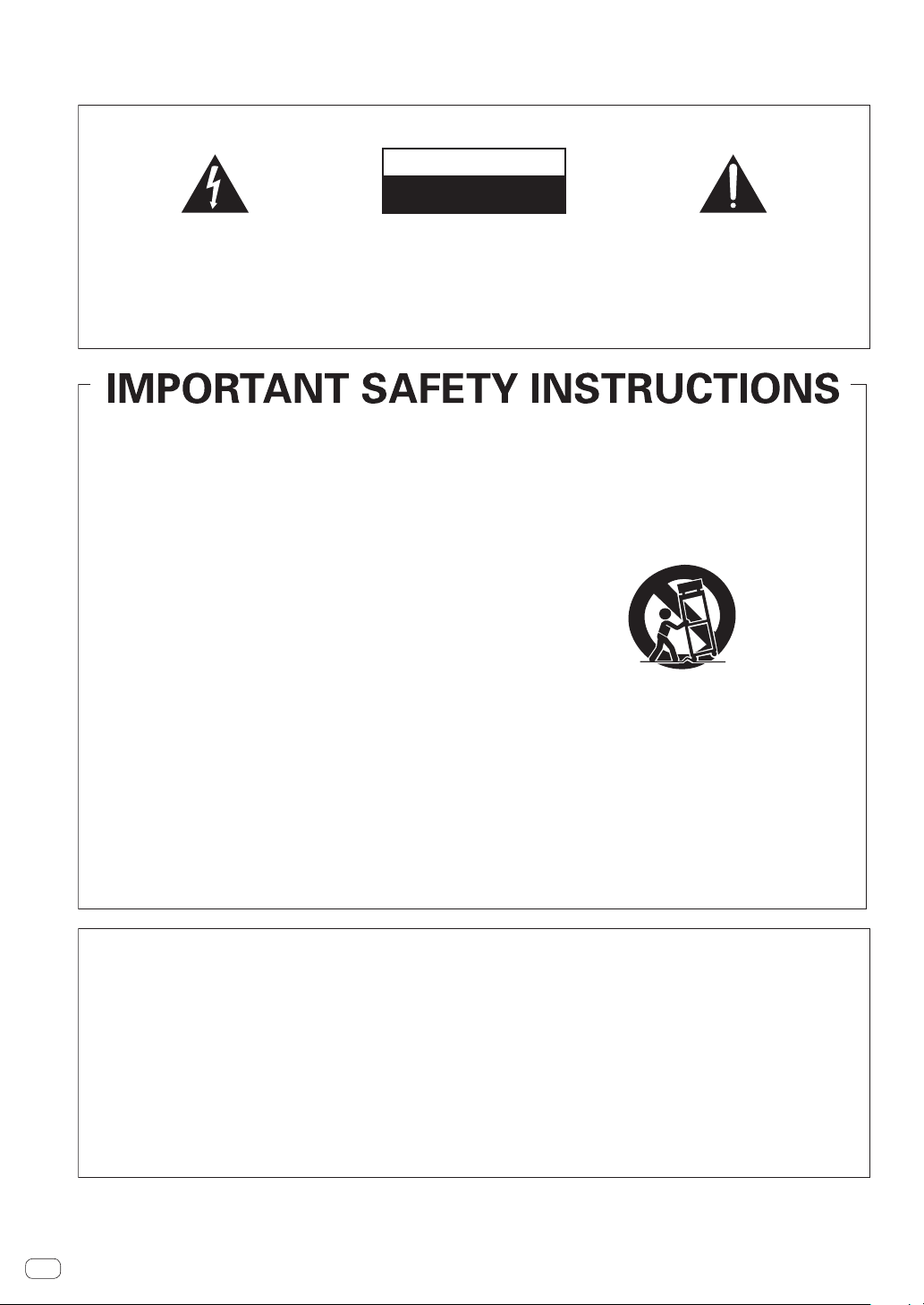
CAUTION
RISK OF ELECTRIC SHOCK
DO NOT OPEN
The lightning flash with arrowhead symbol,
within an equilateral triangle, is intended to
alert the user to the presence of uninsulated
“dangerous voltage” within the product’s
enclosure that may be of sufficient
magnitude to constitute a risk of electric
shock to persons.
Read these instructions.
1)
Keep these instructions.
2)
Heed all warnings.
3)
Follow all instructions.
4)
Do not use this apparatus near water.
5)
Clean only with dry cloth.
6)
Do not block any ventilation openings. Install in
7)
CAUTION:
TO PREVENT THE RISK OF ELECTRIC
SHOCK, DO NOT REMOVE COVER (OR
BACK). NO USER-SERVICEABLE PARTS
INSIDE. REFER SERVICING TO QUALIFIED
SERVICE PERSONNEL.
accordance with the manufacturer’s
instructions.
Do not install near any heat sources such as
8)
radiators, heat registers, stoves, or other
apparatus (including amplifiers) that produce
heat.
Do not defeat the safety purpose of the polarized
9)
or grounding-type plug. A polarized plug has two
blades with one wider than the other. A
grounding type plug has two blades and a third
grounding prong. The wide blade or the third
prong are provided for your safety. If the provided
plug does not fit into your outlet, consult an
electrician for replacement of the obsolete outlet.
Protect the power cord from being walked on or
10)
pinched particularly at plugs, convenience
receptacles, and the point where they exit from
the apparatus.
11)
Only use attachments/accessories specified by
the manufacturer.
12)
Use only with the cart, stand, tripod, bracket, or
table specified by the manufacturer, or sold with
the apparatus. When a cart is used, use caution
when moving the cart/apparatus combination to
avoid injury from tip-over.
13)
Unplug this apparatus during lightning storms
or when unused for long periods of time.
14)
Refer all servicing to qualified service personnel.
Servicing is required when the apparatus has
been damaged in any way, such as power-supply
cord or plug is damaged, liquid has been spilled
or objects have fallen into the apparatus, the
apparatus has been exposed to rain or moisture,
does not operate normally, or has been dropped.
The exclamation point within an equilateral
triangle is intended to alert the user to the
presence of important operating and
maintenance (servicing) instructions in the
literature accompanying the appliance.
D3-4-2-1-1b_A1_En
D3-7-13-69_En
NOTE:
This equipment has been tested and found to comply with the limits for a Class B digital device, pursuant to Part 15
of the FCC Rules. These limits are designed to provide reasonable protection against harmful interference in a
residential installation. This equipment generates, uses, and can radiate radio frequency energy and, if not installed
and used in accordance with the instructions, may cause harmful interference to radio communications. However,
there is no guarantee that interference will not occur in a particular installation. If this equipment does cause
harmful interference to radio or television reception, which can be determined by turning the equipment off and on,
the user is encouraged to try to correct the interference by one or more of the following measures:
— Reorient or relocate the receiving antenna.
— Increase the separation between the equipment and receiver.
— Connect the equipment into an outlet on a circuit different from that to which the receiver is connected.
— Consult the dealer or an experienced radio/TV technician for help.
En
2
D8-10-1-2_A1_En
Page 3

FEDERAL COMMUNICATIONS COMMISSION DECLARATION OF CONFORMITY
This device complies with part 15 of the FCC Rules. Operation is subject to the following two conditions: (1) This
device may not cause harmful interference, and (2) this device must accept any interference received, including
interference that may cause undesired operation.
Product Name: DJ MIXER
Model Number: DJM-750-K, DJM-750-S
Responsible Party Name: PIONEER ELECTRONICS (USA) INC.
SERVICE SUPPORT DIVISION
Address: 1925 E. DOMINGUEZ ST. LONG BEACH, CA 90810-1003, U.S.A.
Phone: 1-800-421-1404
URL: http://www.pioneerelectronics.com
D8-10-4*_C1_En
CAUTION
This product satisfies FCC regulations when shielded cables and connectors are used to connect the unit to other
equipment. To prevent electromagnetic interference with electric appliances such as radios and televisions, use
shielded cables and connectors for connections.
D8-10-3a_A1_En
WARNING
This equipment is not waterproof. To prevent a fire or
shock hazard, do not place any container filled with
liquid near this equipment (such as a vase or flower
pot) or expose it to dripping, splashing, rain or
moisture.
D3-4-2-1-3_A1_En
WARNING
This product equipped with a three-wire grounding
(earthed) plug - a plug that has a third (grounding) pin.
This plug only fits a grounding-type power outlet. If you
are unable to insert the plug into an outlet, contact a
licensed electrician to replace the outlet with a properly
grounded one. Do not defeat the safety purpose of the
grounding plug.
D3-4-2-1-6_A1_En
WARNING
To prevent a fire hazard, do not place any naked flame
sources (such as a lighted candle) on the equipment.
D3-4-2-1-7a_A1_En
Operating Environment
Operating environment temperature and humidity:
+5 °C to +35 °C (+41 °F to +95 °F); less than 85 %RH
(cooling vents not blocked)
Do not install this unit in a poorly ventilated area, or in
locations exposed to high humidity or direct sunlight (or
strong artificial light).
D3-4-2-1-7c*_A2_En
VENTILATION CAUTION
When installing this unit, make sure to leave space
around the unit for ventilation to improve heat radiation
(at least 5 cm at rear, and 3 cm at each side).
WARNING
Slots and openings in the cabinet are provided for
ventilation to ensure reliable operation of the product,
and to protect it from overheating. To prevent fire
hazard, the openings should never be blocked or
covered with items (such as newspapers, table-cloths,
curtains) or by operating the equipment on thick carpet
or a bed.
D3-4-2-1-7b*_A1_En
CAUTION
The POWER switch on this unit will not completely
shut off all power from the AC outlet. Since the power
cord serves as the main disconnect device for the
unit, you will need to unplug it from the AC outlet to
shut down all power. Therefore, make sure the unit
has been installed so that the power cord can be
easily unplugged from the AC outlet in case of an
accident. To avoid fire hazard, the power cord should
also be unplugged from the AC outlet when left
unused for a long period of time (for example, when
on vacation).
D3-4-2-2-2a*_A1_En
The Safety of Your Ears is in Your Hands
Get the most out of your equipment by playing it at a
safe level – a level that lets the sound come through
clearly without annoying blaring or distortion and, most
importantly, without affecting your sensitive hearing.
Sound can be deceiving. Over time, your hearing
“comfort level” adapts to higher volumes of sound, so
what sounds “normal” can actually be loud and
harmful to your hearing. Guard against this by setting
your equipment at a safe level BEFORE your hearing
adapts.
ESTABLISH A SAFE LEVEL:
• Set your volume control at a low setting.
• Slowly increase the sound until you can hear it
comfortably and clearly, without distortion.
• Once you have established a comfortable sound
level, set the dial and leave it there.
BE SURE TO OBSERVE THE FOLLOWING
GUIDELINES:
• Do not turn up the volume so high that you can’t
hear what’s around you.
• Use caution or temporarily discontinue use in
potentially hazardous situations.
• Do not use headphones while operating a motorized
vehicle; the use of headphones may create a traffic
hazard and is illegal in many areas.
S001a_A1_En
En
3
Page 4
Information to User
Alterations or modifications carried out without
appropriate authorization may invalidate the user’s
right to operate the equipment.
D8-10-2_A1_En
WARNING: Handling the cord on this product or
cords associated with accessories sold with the
product may expose you to chemicals listed on
proposition 65 known to the State of California and
other governmental entities to cause cancer and
birth defect or other reproductive harm.
D36-P5_B1_En
IMPORTANT NOTICE
THE MODEL NUMBER AND SERIAL NUMBER OF
THIS EQUIPMENT ARE ON THE REAR OR BOTTOM.
RECORD THESE NUMBERS ON PAGE 11 FOR
FUTURE REFERENCE.
D36-AP9-3*_A1_En
WARNING
Store small parts out of the reach of children and
infants. If accidentally swallowed, contact a doctor
immediately.
D41-6-4_A1_En
This Class B digital apparatus complies with
Canadian ICES-003.
D8-10-1-3_A1_En
POWER-CORD CAUTION
Handle the power cord by the plug. Do not pull out the
plug by tugging the cord and never touch the power
cord when your hands are wet as this could cause a
short circuit or electric shock. Do not place the unit, a
piece of furniture, etc., on the power cord, or pinch the
cord. Never make a knot in the cord or tie it with other
cords. The power cords should be routed such that they
are not likely to be stepped on. A damaged power cord
can cause a fire or give you an electrical shock. Check
the power cord once in a while. When you find it
damaged, ask your nearest PIONEER authorized
service center or your dealer for a replacement.
S002*_A1_En
En
4
Page 5

Before you start
Analog player Analog player
CU
How to read this manual
Be sure to read both this leaflet and the Operating Instructions contained on the CD-ROM accompanying this product! Both documents include important information that you must understand before using this product.
! In this manual, names of channels and buttons indicated on the product, names of menus in the software, etc., are indicated within square brack-
ets ([ ]). (e.g. [MASTER] channel, [ON/OFF], [File] menu)
What’s in the box
! Driver software/operating instructions CD-ROM
! USB cable
! Power cord
! Read Before Use (Important)/Quick Start Guide (this document)
Connections
Be sure to turn off the power and unplug the power cord from the power outlet whenever making or changing connections.
Refer to the operating instructions for the component to be connected.
Connect the power cord after all the connections between devices have been completed.
Be sure to use the included power cord.
Computer
Before you start
L
1 2 534
SEND
L
(MONO)
LR
(MONO)
PHONOCD/LINE
RETURN
OFF
POWER
ON
AC IN
R
R
CH 4CH 3
L
R
LINECD/LINE
L
SIGNAL GNDSIGNAL GND
MASTER1
R
1 GND
2 HOT
3 COLD
REC OUTMASTER2
L
L
R
CH 2
LINECD/LINE
L
R
L
R
Be sure to connect using
the included USB cable.
CH 1
PHONO
CD/LINE
L
RR
BOOTH
L
R
DIGITAL
MASTER OUT
LR
CONTROL
CH3
CH2
Microphone
MI
b
c
MIC
LEVEL
Headphones
MASTER
a 9 8 7 6
R
L
To power outlet
R
L
Power amplifier
12
R
L
Pioneer DJ players
R
L
Power amplifier
(for booth monitor)
d
CUE
LEVEL
PHONES
0
! To use the fader start function, connect a control cable (page 9).
1 Be sure to use the [MASTER1] terminals only for a balanced output. Connection with an unbalanced input (such as RCA) using an XLR to RCA
converter cable (or converter adapter), etc., may lower the sound quality and/or result in noise.
For connection with an unbalanced input (such as RCA), use the [MASTER2] terminals.
2 Be careful not to accidentally insert the power cord of another unit to [MASTER1] terminal.
SB
En
5
Page 6

1 POWER button (page 8)
Turns this unit’s power on and off.
2 PHONO terminals
Connect to a phono level (MM cartridge) output device. Do not input
line level signals.
To connect a device to the [PHONO] terminals, remove the shortcircuit pin plug inserted in the terminals.
Insert this short-circuit pin plug into the [PHONO] terminals when
nothing is connected to them to cut external noise.
3 CD/LINE terminals
Connect to a DJ player or a line level output component.
4 SIGNAL GND terminal
Connects an analog player’s ground wire here. This helps reduce
noise when the analog player is connected.
5 LINE terminals
Connect to a cassette deck or a line level output component.
6 CONTROL terminal
This is a Ø 3.5 mm mini phone jack type DJ player control terminal.
If you connect a Pioneer DJ player using a control cable (supplied
with a DJ player), you can start playback of control other operations
of the DJ player with the fader of this unit.
7 BOOTH terminals
These are output terminals for a booth monitor.
8 MASTER2 terminals
Connect to a power amplifier, etc.
9 MASTER1 terminals
Connect to a power amplifier, etc.
Be sure to use these as balanced outputs. Be careful not to acci-
dentally insert the power cord of another unit.
a AC IN
Connects to a power outlet using the included power cord. Wait until
all connections between the equipment are completed before connecting the power cord.
Be sure to use the included power cord.
b MIC terminal (page 9)
Connects a microphone here.
c USB terminal
Connect the computer.
d PHONES terminal (page 8)
Connect headphones here.
WARNING
The short-circuit pin plugs out of the reach of children and infants. If
accidentally swallowed, contact a doctor immediately.
En
6
Page 7

Operation
MIC USB
MIC
LEVEL
1
2
3
4
5
6
7
HI
12 12
LOW
12 12
ON
OFF
MIDI
ON/OFF
FADER START
CH-2 CH-3
HEAD PHONES
MIXING
CUE
LEVEL
PHONES
0
TALK
OVER
STEREOMONO SPLIT
START
/STOP
MASTER
0
EQ
CD/LINE
OVER
dB
Operation
POWER
8
PHONO
1/2
USB
CD/LINE
LINE
3/4
USB
CD/LINE
LINE
USB
PHONO
5/6
CD/LINE
9
TRIM
OVER
TRIM
OVER
TRIM
OVER
TRIM
a
10
7
HI
4
2
1
0
-
26
/
-
1
MID
-
2
-
3
-
5
-
7
-
26
/
-
LOW
10
-
15
-
24
-
26
/
10
b
9
7
HI
4
2
1
0
6
-
26
/
-
1
MID
-
2
EQ /
-
3
ISO
-
5
-
6
7
-
26
/
-
LOW
10
-
15
-
24
dB
6
-
26
/
10
9
7
HI
4
2
1
0
6
-
26
/
-
1
MID
-
2
EQ /
-
3
ISO
-
5
-
6
7
-
26
/
-
LOW
10
-
15
-
24
dB
6
-
26
/
10
9
7
HI
4
2
1
0
6
-
26
/
-
1
MID
-
2
EQ /
-
3
ISO
-
5
-
6
7
-
26
/
-
LOW
10
-
15
-
24
dB
6
-
26
/
MASTER
7/8
USB
LEVEL
g
h
OVER
9
6
EQ /
ISO
6
6
10
7
4
2
1
0
-
1
-
2
-
3
-
5
-
7
-
10
-
15
-
24
dB
CUE
c
HEADPHONE CUE
10
9
8
7
6
5
d
4
3
2
1
0
BA THRU
10
9
8
7
6
5
4
3
2
1
0
BA THRU
10
9
8
7
6
5
4
3
2
1
0
BA THRU
e
BA THRU
c
BALANCE
STEREO
MONO
i
BOOTH MONITOR
j
EQ CURVE
ISOLATOR
k
CH FADER
l
CROSS FADER ASSIGN
CROSS FADER
m
f
BA
0
RL
RL
0
EQ
BEAT EFFECTS
CH SELECT
1 2 3 4
MIC
A B
PARAMETER
AUTO
TAP
BEAT
AUTO
/ TAP
TAP
BOOST
NOISE
CRUSH
SOUND COLOR FX
LOW HI
FLANGER
PHASER
FILTER
TRANS
REVERB
SPIRAL
ECHO
DELAY
4
3
2
1
TIME
LEVEL /DEPTH
MIN
ON/ OFF
MIC
MST
BPM
%
ms
ROBOT
VINYL BRAKE
SLIP ROLL
ROLL
REV ROLL
SND/ RTN
CF.A
CF.B
MASTER
MAX
n
SETUP
WAKE UP
JET
FILTER
CUE
1 MIC LEVEL control (page 9)
Adjusts the sound level output from the [MIC] channel.
2 EQ (HI, LOW) controls (page 9)
Adjusts the sound quality of the [MIC] channel.
3 OFF, ON, TALK OVER selector switch (page 9)
Turns the microphone on/off.
4 FADER START (CH-2, CH-3) buttons (page 9)
These turn the fader start function on/off.
5 MONO SPLIT, STEREO selector switch (page 8)
Switches how the monitor sound output from the headphones is
distributed.
6 MIXING control (page 8)
This adjusts the monitor volume balance of the sound of channels for
which the [CUE] button is pressed and the sound of the [MASTER]
channel.
7 LEVEL control (page 8)
Adjusts the sound level output from the headphones.
8 Input selector switches (page 8)
Selects the input source of each channel from the components connected to this unit.
9 Channel Level Indicator (page 8)
Displays the sound level of the respective channels before passing
through the channel faders.
a TRIM control (page 8)
Adjusts the level of audio signals input in each channel.
En
7
Page 8

b EQ/ISO (HI, MID, LOW) controls (page 8)
These adjust the sound quality of the respective channels.
c CUE button (page 8)
Presses the [CUE] button(s) for the channel(s) you want to monitor.
d Channel Fader (page 8)
Adjusts the level of audio signals output in each channel.
e CROSS FADER ASSIGN (A, THRU, B) selector switch
(page 8)
Sets the output destination of each channel to [A] or [B].
f Crossfader (page 8)
Outputs audio signals assigned by the crossfader assign switch corresponding to the curve characteristics selected by [CROSS FADER]
(Crossfader Curve Selector Switch).
g MASTER LEVEL control (page 8)
Adjusts the audio level output from the [MASTER1] and [MASTER2]
terminals.
h Master Level Indicator (page 8)
Displays the audio level output from the [MASTER1] and [MASTER2]
terminals.
i MONO, STEREO selector switch (page 9)
Switches the sound output from the [MASTER1] terminals, etc.,
between monaural and stereo.
j BOOTH MONITOR control (page 9)
Adjusts the level of audio signals output from the [BOOTH] terminal.
k EQ CURVE (ISOLATOR, EQ) selector switch (page 8)
Switches the function of the [EQ/ISO (HI, MID, LOW)] controls.
l CH FADER ( , ) selector switch (page 9)
Switches the channel fader’s curve characteristics.
m CROSS FADER ( , , ) selector switch (page 9)
This switches the crossfader curve characteristics.
n Main unit display
Do not pull on the channel fader and crossfader knobs with excessive
force. The knobs have a structure by which they cannot be pulled off
easily. Pulling the knobs strongly may result in damaging the unit.
Basic Operation
Outputting sound
1 Press [POWER] button.
Turn on the power of this unit.
2 Switch the input selector switches.
Selects the input sources for the different channels from among the
devices connected to this unit.
— [PHONO]: Selects the analog player connected to the [PHONO]
terminals.
— [CD/LINE], [LINE]: Selects the DJ player or cassette deck con-
nected to the [CD/LINE] or [LINE] terminals.
— [USB */*]: Selects the sound of the computer connected to the
[USB] port.
3 Turn the [TRIM] control.
Adjusts the level of audio signals input in each channel.
The corresponding channel level indicator lights when audio signals are
being properly input to that channel.
4 Move the channel fader away from you.
Adjusts the level of audio signals output in each channel.
5 Switch the [CROSS FADER ASSIGN (A, THRU, B)]
selector switch.
Switches the output destination of each channel.
— [A]: Assigns to [A] (left) of the crossfader.
— [B]: Assigns to [B] (right) of the crossfader.
— [THRU]: Selects this when you do not want to use the crossfader.
(The signals do not pass through the crossfader.)
6 Set the crossfader.
This operation is not necessary when the [CROSS FADER ASSIGN (A,
THRU, B)] selector switch is set to [THRU].
7 Turn the [MASTER LEVEL] control.
Audio signals are output from the [MASTER1] and [MASTER2]
terminals.
The master level indicator lights.
Adjusting the sound quality
Turn the [EQ/ISO (HI, MID, LOW)] controls for the
respective channels.
The adjustable ranges for the respective controls are as shown below.
! HI: –26 dB to +6 dB (13 kHz)
! MID: –26 dB to +6 dB (1 kHz)
! LOW: –26 dB to +6 dB (70 Hz)
Switching the function of the [EQ/ISO (HI, MID,
LOW)] controls
Switch the [EQ CURVE (ISOLATOR, EQ)] selector switch.
— [ISOLATOR]: Functions as an isolator.
— [EQ]: The equalizer function is set.
Monitoring sound with headphones
1 Connect headphones to the [PHONES] terminal.
2 Press the [CUE] button(s) for the channel(s) you want
to monitor.
3 Switch the [MONO SPLIT, STEREO] selector switch.
— [MONO SPLIT]: The sound of the channels for which the [CUE]
button is pressed is output from the headphones output’s left
channel, the [MASTER] channel sound is output from the right
channel.
— [STEREO]: The sound of the channels for which the [CUE] button
is pressed is output from the headphones in stereo.
En
8
Page 9

4 Turn the [MIXING] control.
This adjusts the monitor volume balance of the sound of channels for
which the [CUE] button is pressed and the sound of the [MASTER]
channel.
5 Turn the [LEVEL] control for [HEADPHONES].
The sound of the channels for which the [CUE] button is pressed is
output from the headphones.
! When the [CUE] button is pressed again, monitoring is canceled.
Switching the fader curve
Select the channel fader curve characteristics
Switch the [CH FADER (
— [ ]: The curve rises suddenly at the back side.
— [ ]: The curve rises gradually (the sound gradually increases as
the channel fader is moved away from the front side).
, )] selector switch.
Select the crossfader curve characteristics
Switch the [CROSS FADER (
— [ ]: Makes a sharply increasing curve (if the crossfader is
moved away from the [A] side, audio signals are immediately
output from the [B] side).
— [ ]: Makes a curve shaped between the two curves above and
below.
— [ ]: Makes a gradually increasing curve (if the crossfader is
moved away from the [A] side, the sound on the [B] side gradually increases, while the sound on the [A] gradually decreases).
, , )] selector switch.
Starting playback on a DJ player using
the fader (fader start)
If you connect a Pioneer DJ player using a control cable (supplied with
a DJ player), you can start playback of control other operations of the DJ
player with the fader of this unit.
Connect this unit and Pioneer DJ player beforehand. For instructions on
connections, see Connections on page 5.
Start playback using the channel fader
1 Set the [CROSS FADER ASSIGN (A, THRU, B)] selector
switch to [THRU].
2 Press one of the [FADER START (CH-2, CH-3)] buttons.
Select the channel to be started with the fader start function.
3 Set the channel fader to the nearest position towards
you.
4 Set the cue on the DJ player.
The DJ player pauses playback at the cue point.
5 Move the channel fader away from you.
Playback starts on the DJ player.
! If you set the channel fader back to the original position, the player
instantaneously returns to the cue point already set and pauses
playback (back cue).
Start playback using the crossfader
1 Set the [CROSS FADER ASSIGN (A, THRU, B)] selector
switch to [A] or [B].
2 Press one of the [FADER START (CH-2, CH-3)] buttons.
Select the channel to be started with the fader start function.
3 Set the crossfader.
Set to the edge opposite the side on which the channel you want to use
with the fader start function is set.
4 Set the cue on the DJ player.
The DJ player pauses playback at the cue point.
5 Set the crossfader.
Playback starts on the DJ player.
! If you set the crossfader back to the original position, the player
instantaneously returns to the cue point already set and pauses
playback (back cue).
Using a microphone
1 Connect the microphone to the [MIC] jack.
2 Set the [OFF, ON, TALK OVER] selector switch to [ON]
or [TALK OVER].
— [ON]: The indicator lights.
— [TALK OVER]: The indicator flashes.
! When set to [TALK OVER], the sound of channels other than the
[MIC] channel is attenuated by 18 dB (default) when a sound of –10
dB or greater is input to the microphone.
! The audio attenuation level for the [TALK OVER] mode can be
changed at the [USER SETUP] screen. For instructions on changing
the level, see this product’s operating instructions.
! The talk over mode can be switched between the normal mode and
the advanced mode. For instructions on changing the mode, see this
product’s operating instructions.
3 Turn the [MIC LEVEL] control.
Adjust the level of the sound output from the [MIC] channel.
! Pay attention that rotating to the extreme right position outputs a
very loud sound.
4 Input audio signals to the microphone.
Adjusting the sound quality
Turn the [MIC] channels’ [EQ (HI, LOW)] controls.
The adjustable ranges for the respective controls are as shown below.
! HI: –12 dB to +12 dB (10 kHz)
! LOW: –12 dB to +12 dB (100 Hz)
Switching between monaural and stereo
audio
This switches the sound output from the [MASTER1], [MASTER2],
[BOOTH], [REC OUT], [PHONES], [DIGITAL MASTER OUT] and [USB]
terminals between monaural and stereo.
! To adjust the sound output from the [USB] terminals, select [REC
OUT] at [Mixer Audio Output] in the setting utility.
Switch the [MONO, STEREO] selector switch.
— [MONO]: Outputs monaural audio.
— [STEREO]: Outputs stereo audio.
Adjusting the L/R balance of audio
The left/right balance of the sound output from the [MASTER1],
[MASTER2], [BOOTH], [REC OUT], [PHONES], [DIGITAL MASTER OUT]
and [USB] terminals can be adjusted.
! To adjust the sound output from the [USB] terminals, select [REC
OUT] at [Mixer Audio Output] in the setting utility.
1 Set the [MONO, STEREO] selector switch to [STEREO].
2 Turn the [BALANCE] control.
The sound’s left/right balance changes according to the direction in
which the [BALANCE] control is turned and its position.
! Rotating to the rightmost position outputs only the right sound of
stereo audio. Rotating to the leftmost position outputs only the left
sound of stereo audio.
Audio is output from the [BOOTH]
terminal
Turn the [BOOTH MONITOR] control.
Adjusts the level of audio signals output from the [BOOTH] terminal.
En
Operation
9
Page 10

Additional information
About trademarks and registered
trademarks
! Pioneer is a registered trademark of PIONEER CORPORATION.
! Microsoft, Windows and Windows Vista are either registered trade-
marks or trademarks of Microsoft Corporation in the United States
and/or other countries.
! Apple, Macintosh and Mac OS are trademarks of Apple Inc., regis-
tered in the U.S. and other countries.
! ASIO is a trademark of Steinberg Media Technologies GmbH.
! The names of companies and products mentioned herein are the
trademarks of their respective owners.
Specifications
General
Power requirements .............................................................AC 120 V, 60 Hz
Power consumption ............................................................................... 30 W
Power consumption (standby) ........................................................... 0.45 W
Main unit weight ........................................................................7.6 kg (17 lb)
Max. dimensions ....................... 320 mm (W) × 108 mm (H) × 376 mm (D)
(12.6 in. (W) × 4.3 in. (H) × 14.8 in. (D))
Tolerable operating temperature ......... +5 °C to +35 °C (+41 °F to +95 °F)
Tolerable operating humidity ...................... 5 % to 85 % (no condensation)
Audio Section
Sampling rate ......................................................................................96 kHz
MASTER D/A converter .......................................................................24 bits
Other A/D and D/A converters ............................................................24 bits
Frequency characteristic
CD/LINE ........................................................................... 20 Hz to 20 kHz
S/N ratio (rated output, A-WEIGHTED)
PHONO............................................................................................ 92 dB
CD/LINE ......................................................................................... 106 dB
MIC .................................................................................................. 84 dB
Total harmonic distortion (20 kHzBW)
CD/LINE — MASTER1.................................................................0.004 %
Standard input level / Input impedance
PHONO............................................................................. –52 dBu/47 kW
CD/LINE ............................................................................ –12 dBu/47 kW
MIC .................................................................................. –52 dBu/8.5 kW
RETURN ............................................................................ –12 dBu/49 kW
Standard output level / Load impedance / Output impedance
MASTER1 ................................................ +6 dBu/10 kW /360 W or lower
MASTER2 ................................................ +2 dBu/10 kW /390 W or lower
REC OUT .....................................................–8 dBu/10 kW/22 W or lower
BOOTH .................................................... +2 dBu/10 kW /390 W or lower
SEND .......................................................–12 dBu/10 kW/390 W or lower
PHONES ................................................... +8.5 dBu/32 W/10 W or lower
Rated output level / Load impedance
MASTER1 ........................................................................+24 dBu/10 kW
MASTER2 ........................................................................+20 dBu/10 kW
Crosstalk
LINE ................................................................................................. 82 dB
Channel equalizer characteristic
HI .....................................................................–26 dB to +6 dB (13 kHz)
MID ....................................................................–26 dB to +6 dB (1 kHz)
LOW ..................................................................–26 dB to +6 dB (70 Hz)
Microphone equalizer characteristic
HI ...................................................................–12 dB to +12 dB (10 kHz)
LOW ..............................................................–12 dB to +12 dB (100 Hz)
Input / Output terminals
PHONO input terminal
RCA pin jack .................................................................................... 2 sets
CD/LINE input terminal
RCA pin jacks .................................................................................. 4 sets
LINE input terminal
RCA pin jack .................................................................................... 2 sets
MIC input terminal
XLR connector/phone jack (Ø 6.3 mm) ........................................... 1 set
RETURN Input terminals
Phone jack (Ø 6.3 mm) ..................................................................... 1 set
MASTER output terminal
XLR connector...................................................................................1 set
RCA pin jacks ....................................................................................1 set
BOOTH output terminal
RCA pin jacks ....................................................................................1 set
REC OUT output terminal
RCA pin jacks ....................................................................................1 set
SEND output terminal
Phone jack (Ø 6.3 mm) ..................................................................... 1 set
DIGITAL MASTER OUT coaxial output terminal
RCA pin jacks ....................................................................................1 set
PHONES output terminal
Stereo phone jack (Ø 6.3 mm) .........................................................1 set
USB terminal
B type .................................................................................................1 set
CONTROL terminal
Mini phone jack (Ø 3.5 mm) ........................................................... 2 sets
— The specifications and design of this product are subject to
change without notice.
— Be sure to use the [MASTER1] terminals only for a balanced
output. Connection with an unbalanced input (such as RCA)
using an XLR to RCA converter cable (or converter adapter), etc.,
may lower the sound quality and/or result in noise.
For connection with an unbalanced input (such as RCA), use the
[MASTER2] terminals.
10
En
Page 11

PIONEER ELECTRONICS (USA) INC.
WARRANTY VALID ONLY IN THE U.S.A. AND CANADA
WARRANTY
Pioneer Electronics (USA) Inc. (PUSA) warrants that products distributed by PUSA in the U.S.A. and Canada that fail to function properly under normal use due to a manufacturing
defect when installed and operated according to the owner’s manual enclosed with the unit will be repaired or replaced with a unit of comparable value, at the option of PUSA,
without charge to you for parts or actual repair work. Parts supplied under this warranty may be new or rebuilt at the option of PUSA.
THIS LIMITED WARRANTY APPLIES TO THE ORIGINAL OR ANY SUBSEQUENT OWNER OF THIS PIONEER PRODUCT DURING THE WARRANTY PERIOD PROVIDED THE
PRODUCT WAS PURCHASED FROM AN AUTHORIZED PIONEER DISTRIBUTOR/DEALER IN THE U.S.A. OR CANADA. YO U WILL BE REQUIRED TO PROVIDE A SALES
RECEIPT OR OTHER VALID PROOF OF PURCHASE SHOWING THE DATE OF ORIGINAL PURCHASE OR, IF RENTED, YOUR RENTAL CONTRACT SHOWING THE PLACE
AND DATE OF FIRST RENTAL. IN THE EVENT SERVICE IS REQUIRED, THE PRODUCT MUST BE DELIVERED WITHIN THE WARRANTY PERIOD, TRANSPORTATION
PREPAID, ONLY FROM WITHIN THE U.S.A. AS EXPLAINED IN THIS DOCUMENT. YOU WILL BE RESPONSIBLE FOR REMOVAL AND INSTALLATION OF THE PRODUCT .
PUSA WILL PAY TO RETURN THE REPAIRED OR REPLACEMENT PRODUCT TO YO U WITHIN THE U.S.A.
PRODUCT WARRANTY PERIOD
DJ Audio and Video ................................................................................................................................................................................... 1 Year 1 Year
The warranty period for retail customers who rent the product commences upon the date product is first put into use (a) during the rental period or (b) retail sale, whichever occurs first.
WHAT IS NOT COVERED
IF THIS PRODUCT WAS PURCHASED FROM AN UNAUTHORIZED DISTRIBUTOR, THERE ARE NO WARRANTIES, EXPRESS OR IMPLIED, INCLUDING THE IMPLIED WARRANTY
OF MERCHANTABILITY AND THE IMPLIED WARRANTY OF FITNESS FOR A PARTICULAR PURPOSE AND THIS PRODUCT IS SOLD STRICTLY “AS IS” AND “WITH ALL FAULTS".
PIONEER SHALL NOT BE LIABLE FOR ANY CONSEQUENTIAL AND/OR INCIDENTAL DAMAGES.
THIS WARRANTY DOES NOT APPLY IF THE PRODUCT HAS BEEN SUBJECTED TO POWER IN EXCESS OF ITS PUBLISHED POWER RATING.
THIS WARRANTY DOES NOT COVER THE CABINET OR ANY APPEARANCE ITEM, USER ATTA CHED ANTENNA, ANY DAMAGE TO RECORDS OR RECORDING TA PES OR DISCS, ANY
DAMAGE TO THE PRODUCT RESULTING FROM ALTERATIONS, MODIFICA
LIGHTNING OR TO POWER SURGES, SUBSEQUENT DAMAGE FROM LEAKING, DAMAGE FROM INOPERATIVE BATTERIES, OR THE USE OF BATTERIES NOT CONFORMING TO THOSE
SPECIFIED IN THE OWNER’S MANUAL.
THIS WARRANTY DOES NOT COVER THE COST OF PARTS OR LABOR WHICH WOULD BE OTHERWISE PROVIDED WITHOUT CHARGE UNDER THIS WARRANTY OBTAINED FROM
ANY SOURCE OTHER THAN A PIONEER AU THORIZED SERVICE COMPANY OR OTHER DESIGNATED LOCATION. THIS WARRANTY DOES NOT COVER DEFECTS OR DAMAGE CAUSED
BY THE USE OF UNAUTHORIZED PARTS OR LABOR OR FROM IMPROPER MAINTENANCE.
ALTERED, DEFACED, OR REMOVED SERIAL NUMBERS VOID THIS ENTIRE WARRANTY
NO OTHER WARRANTIES
PIONEER LIMITS ITS OBLIGATIONS UNDER ANY IMPLIED WARRANTIES INCLUDING, BUT NOT LIMITED TO, THE IMPLIED WARRANTIES OF MERCHANTABILITY AND
FITNESS FOR A PARTICULAR PURPOSE, TO A PERIOD NOT TO EXCEED THE WARRANTY PERIOD. NO WARRANTIES SHALL APPLY AFTER THE WARRANTY PERIOD.
SOME STATES DO NOT ALLOW LIMITATIONS ON HOW LONG AN IMPLIED WARRANTY LASTS AND SOME STATES DO NOT ALLOW THE EX CLUSIONS OR LIMITATIONS
OF INCIDENTAL OR CONSEQUENTIAL DAMAGES, SO THE ABOVE LIMITATIONS OR EXCLUSIONS MAY NOT APPLY TO YOU. THIS WARRANTY GIVES YOU SPECIFIC LEGAL
RIGHTS AND YOU MAY HAVE OTHER RIGHTS WHICH MAY VA RY FROM STATE TO STATE.
TO OBTAIN SERVICE
PUSA has appointed a number of Authorized Service Companies throughout the U.S.A. and Canada should your product require service. To receive warranty service you
need to present your sales receipt or, if rented, your rental contract showing place and date of original owner’s transaction. If shipping the unit you will need to package it
carefully and send it, transportation prepaid by a traceable, insured method, to an Authorized Service Company. Package the product
prevent damage in transit. The original container is ideal for this purpose. Include your name, address and telephone number where you can be reached during business
hours.
On all complaints and concerns in the U.S.A. and Canada call Customer Support at 1-800-872-4159.
LIMITED WARRANTY
Parts Labor
TIONS NOT AUTHORIZED IN WRITING BY PIONEER, ACCIDENT, MISUSE OR ABUSE, DAMAGE DUE TO
using adequate padding material to
Additional information
For hook-up and operation of your unit or to locate an
Authorized Service Company, please call or write:
DISPUTE RESOLUTION
Following our response to any initial request to Customer Support, should a dispute arise between you and Pioneer, Pioneer makes available its Complaint Resolution Program
to resolve the dispute. The Complaint Resolution Program is available to you without charge. Yo u are required to use the Complaint Resolution Program before you exercise
any rights under, or seek any remedies, created by Title I of the Magnuson-Moss Warranty-Federal Trade Commission Improvement Act, 15 U.S.C. 2301 et seq.
To use the Complaint Resolution Program call 1-800-872-4159 and explain to the customer service representative the problem you are experiencing, steps you have take n
to have the product repaired dur ing the warranty period and the name of the authorized Distributor/Dealer from whom the Pioneer product was purchased. After the complaint
has been explained to the representative, a resolution number will be issued. Within 40 days of receiving your complaint, Pioneer will investigate the dispute and will either:
(1) respond to your complaint in writing infor ming you what action Pioneer will take, and in what time period, to resolve the dispute; or (2) respond to your complaint in writing
informing you why it will not take any action.
CUSTOMER SUPPORT
PIONEER ELECTRONICS (USA) INC.
LONG BEACH, CALIFORNIA 90801
P.O. BOX 1720
1-800-872-4159
http://www.pioneerelectronics.com
RECORD THE PLACE AND DATE OF PURCHASE FOR FUTURE REFERENCE
Model No. ____________________________________________ Serial No. _________________________________________ Purchase Date ______________________
Purchased From ____________________________________________________________________________________________________________________________
KEEP THIS INFORMATION AND YOUR SALES RECEIPT IN A SAFE PLACE
UCP0212
_
En
11
Page 12

To register your product, find the nearest authorized service location, to
purchase replacement parts, operating instructions, or accessories,
please go to one of following URLs :
Pour enregistrer votre produit, trouver le service après-vente agréé le plus
proche et pour acheter des pièces de rechange, des modes d’emploi ou
des accessoires, reportez-vous aux URL suivantes :
In the USA & Canada/Aux Etats-Unis & Canada
http://www.pioneerelectronics.com
S018_B1_EnFr_PSV
PIONEER CORPORATION
1-1, Shin-ogura, Saiwai-ku, Kawasaki-shi, Kanagawa 212-0031, Japan
PIONEER ELECTRONICS (USA) INC.
P. O. BOX 1720, Long Beach, California 90801-1720, U.S.A. TEL: (800) 421-1404
K002_PSV_CU
© 2013 PIONEER CORPORATION.
All rights reserved.
<DRH1206-A>Printed in
 Loading...