

Page 1
DJ MIXER
MESA DE MEZCLAS DJ
DJM-5000
Operating Instructions
Manual de instrucciones
ᐈձКь
Page 2
En
2
Thank you for buying this Pioneer product. Please read through these operating instructions so you will know how to operate your model properly. After you have fin-
The exclamation point within an equilateral
triangle is intended to alert the user to the
presence of important operating and
maintenance (servicing) instructions in the
literature accompanying the appliance.
The lightning flash with arrowhead symbol,
within an equilateral triangle, is intended to
alert the user to the presence of uninsulated
“dangerous voltage” within the product’s
enclosure that may be of sufficient
magnitude to constitute a risk of electric
shock to persons.
CAUTION:
TO PREVENT THE RISK OF ELECTRIC
SHOCK, DO NOT REMOVE COVER (OR
BACK). NO USER-SERVICEABLE PARTS
INSIDE. REFER SERVICING TO QUALIFIED
SERVICE PERSONNEL.
CAUTION
RISK OF ELECTRIC SHOCK
DO NOT OPEN
IMPORTANT
D3-4-2-1-1_A1_En
Replacement and mounting of an AC plug on the power supply cord of this unit should be performed only by qualified
service personnel.
D3-4-2-1-2-2_B_En
IMPORTANT: THE MOULDED PLUG
This appliance is supplied with a moulded three pin mains plug for your safety and convenience. A 5 amp fuse is fitted in this plug. Should the
fuse need to be replaced, please ensure that the replacement fuse has a rating of 5 amps and that it is approved by ASTA or BSI to BS1362.
Check for the ASTA mark or the BSI mark on the body of the fuse.
If the plug contains a removable fuse cover, you must ensure that it is refitted when the fuse is replaced. If you lose the fuse cover the plug
must not be used until a replacement cover is obtained. A replacement fuse cover can be obtained from your local dealer.
If the fitted moulded plug is unsuitable for your socket outlet, then the fuse shall be removed and the plug cut off and disposed of
safely. There is a danger of severe electrical shock if the cut off plug is inserted into any 13 amp socket.
If a new plug is to be fitted, please observe the wiring code as shown below. If in any doubt, please consult a qualified electrician.
IMPORTANT: The wires in this mains lead are coloured in accordance with the following code:
Blue : Neutral Brown : Live
As the colours of the wires in the mains lead of this appliance may not correspond with the coloured markings identifying the terminals in
your plug, proceed as follows ;
The wire which is coloured BLUE must be connected to the terminal which is marked with the
letter N or coloured BLACK.
The wire which is coloured BROWN must be connected to the terminal which is marked with the
letter L or coloured RED.
How to replace the fuse: Open the fuse compartment with a screwdriver and replace the fuse.
NOTE:
This equipment has been tested and found to comply with the limits for a Class B digital
device, pursuant to Part 15 of the FCC Rules. These limits are designed to provide
reasonable protection against harmful interference in a residential installation. This
equipment generates, uses, and can radiate radio frequency energy and, if not installed and
used in accordance with the instructions, may cause harmful interference to radio
communications. However, there is no guarantee that interference will not occur in a
particular installation. If this equipment does cause harmful interference to radio or
television reception, which can be determined by turning the equipment off and on, the
user is encouraged to try to correct the interference by one or more of the following
measures:
— Reorient or relocate the receiving antenna.
— Increase the separation between the equipment and receiver.
— Connect the equipment into an outlet on a circuit different from that to which the
receiver is connected.
— Consult the dealer or an experienced radio/TV technician for help.
D8-10-1-2_A1_En
Information to User
Alterations or modifications carried out without appropriate authorization may invalidate
the user’s right to operate the equipment.
D8-10-2_A1_En
CAUTION
This product satisfies FCC regulations when shielded cables and connectors are used to
connect the unit to other equipment. To prevent electromagnetic interference with electric
appliances such as radios and televisions, use shielded cables and connectors for
connections.
D8-10-3a_A1_En
ished reading the instructions, put them away in a safe place for future reference.
In some countries or regions, the shape of the power plug and power outlet may sometimes differ from that shown in the explanatory drawings. However the method of
connecting and operating the unit is the same.
Page 3
En
3
English
FEDERAL COMMUNICATIONS COMMISSION DECLARATION OF CONFORMITY
This device complies with part 15 of the FCC Rules. Operation is subject to the following two conditions: (1) This
device may not cause harmful interference, and (2) this device must accept any interference received, including
interference that may cause undesired operation.
Product Name: DJ MIXER
Model Number: DJM-5000
Responsible Pa rty Name: PIONEER ELECTRONICS (USA), INC.
SERVICE SUPPORT DIVISION
Address: 1925 E. DOMINGUEZ ST. LONG BEACH, CA 90810-1003, U.S.A.
Phone: 1-800-421-1404
URL: http://www.pioneerelectronics.com
D8-10-4*_B1_En
WARNING
This equipment is not waterproof. To prevent a fire
or shock hazard, do not place any container filled
with liquid near this equipment (such as a vase or
flower pot) or expose it to dripping, splashing, rain
or moisture.
D3-4-2-1-3_B_En
WARNING
The voltage of the available power supply differs
according to country or region. Be sure that the
power supply voltage of the area where this unit
will be used meets the required voltage (e.g., 230V
or 120V) written on the rear panel.
D3-4-2-1-4_A_En
Before plugging in for the first time, read the following
section carefully.
WARNING
To prevent a fire hazard, do not place any naked
flame sources (such as a lighted candle) on the
equipment.
D3-4-2-1-7a_A_En
VENTILATION CAUTION
When installing this unit, make sure to leave space
around the unit for ventilation to improve heat
radiation (at least 5 cm at rear, and 3 cm at each
side).
WARNING
Slots and openings in the cabinet are provided for
ventilation to ensure reliable operation of the
product, and to protect it from overheating. To
prevent fire hazard, the openings should never be
blocked or covered with items (such as newspapers,
table-cloths, curtains) or by operating the
equipment on thick carpet or a bed.
D3-4-2-1-7b_A_En
Operating Environment
Operating environment temperature and humidity:
+5 °C to +35 °C (+41 °F to +95 °F); less than 85 %RH
(cooling vents not blocked)
Do not install this unit in a poorly ventilated area, or in
locations exposed to high humidity or direct sunlight (or
strong artificial light)
D3-4-2-1-7c*_A1_En
If the AC plug of this unit does not match the AC
outlet you want to use, the plug must be removed
and appropriate one fitted. Replacement and
mounting of an AC plug on the power supply cord of
this unit should be performed only by qualified
service personnel. If connected to an AC outlet, the
cut-off plug can cause severe electrical shock. Make
sure it is properly disposed of after removal.
The equipment should be disconnected by removing
the mains plug from the wall socket when left unused
for a long period of time (for example, when on
vacation).
D3-4-2-2-1a_A1_En
CAUTION
The POWER switch on this unit will not completely
shut off all power from the AC outlet. Since the
power cord serves as the main disconnect device for
the unit, you will need to unplug it from the AC outlet
to shut down all power. Therefore, make sure the
unit has been installed so that the power cord can
be easily unplugged from the AC outlet in case of an
accident. To avoid fire hazard, the power cord should
also be unplugged from the AC outlet when left
unused for a long period of time (for example, when
on vacation).
D3-4-2-2-2a_A_En
POWER-CORD CAUTION
Handle the power cord by the plug. Do not pull out the
plug by tugging the cord and never touch the power
cord when your hands are wet as this could cause a
short circuit or electric shock. Do not place the unit, a
piece of furniture, etc., on the power cord, or pinch the
cord. Never make a knot in the cord or tie it with other
cords. The power cords should be routed such that they
are not likely to be stepped on. A damaged power cord
can cause a fire or give you an electrical shock. Check
the power cord once in a while. When you find it
damaged, ask your nearest PIONEER authorized
service center or your dealer for a replacement.
S002*_En
When using this product follow the instructions
written on the underside of the unit, which
concern rated voltage, etc.
D3-4-2-2-4_En
For Taiwan exclusively
Taiwanese two pin flat-bladed plug
K056_A1_En
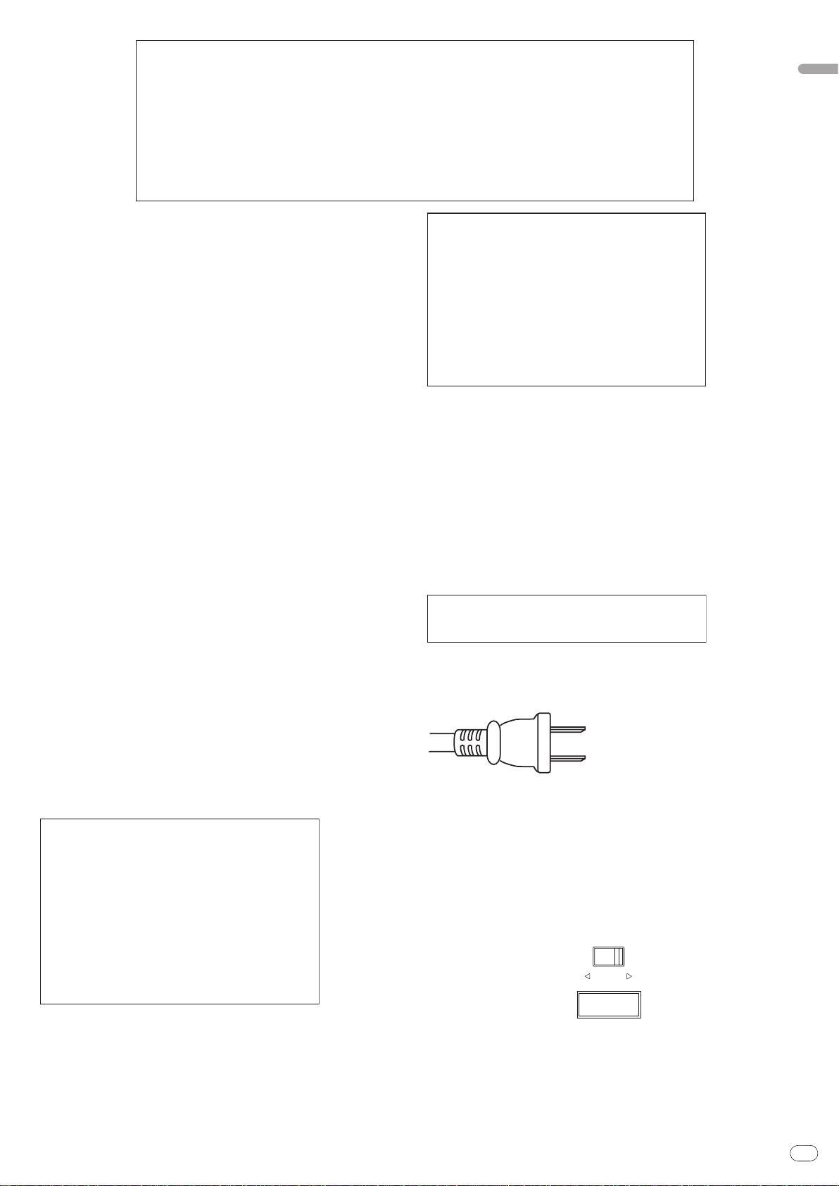
110-120V 220-240V
VOLTAGE
SELECTOR
LINE VOLTAGE SELECTOR SWITCH
The line voltage selector switch is located on the side panel of this mixier.The
factory setting for the voltage selector is 220-240V. Check that it is set properly
before plugging the power cord into the outlet. If the voltage is not properly set or
if you move to an area where the voltage requirements differ, adjust the selector
switch as follows:
! Use a medium-sized (flat blade) screwdriver. Insert the tip of the screwdriver
into the groove of the selector switch and set it so that the power voltage
marking of your area points to the arrow.
! For Taiwan, please set to 110-120V before using.
Page 4
En
4
Contents
How to read this manual
The names of displays, menus, and buttons in this manual are enclosed in brackets. (e.g. [Collection] pane, [File] menu, [f])
Before start
Features ...........................................................................................................................5
What’s in the box .............................................................................................................5
Connections
Rear Panel .......................................................................................................................6
Connecting input terminals ...........................................................................................7
Connecting output terminals .........................................................................................7
Connecting to the control panel ....................................................................................8
Connecting a computer ..................................................................................................8
About the USB audio driver software ............................................................................8
About USB-MIDI channel setting ................................................................................10
Operations
Control Panel .................................................................................................................12
Operating the DJ section..............................................................................................13
Operating the MC section ............................................................................................14
Operating the PA section .............................................................................................15
Additional information
Troubleshooting ............................................................................................................16
About the exemption clauses ......................................................................................16
Block Diagram...............................................................................................................17
Specifications ................................................................................................................18
Mounting on a rack conforming to EIA
standards
The screw holes on the left and right of the control panel of this unit match 5U size
of any EIA standard 19-inch rack. The maximum depth of this unit is 225.1 mm.
! Secure this unit with screws (not supplied) matching the rack.
! Do not install this unit directly above a power amplifier. Heat radiating from the
power amplifier may damage this unit. Also, noise (hum noise, etc.) may be
generated.
! When transporting this unit, remove it from the rack. Transporting this unit
without removing it from the rack may damage this unit.
! If you transport this unit without removing it from the rack, make sure vibration
or shock is not applied to this unit.
Page 5

En
5
Before start
Features
The DJM-5000 is a high quality, high performance mixer designed for high sound
quality and equipped with many functions offering powerful support for three
roles: MC, DJ and PA.
High sound quality processing with 96 kHz sampling, 24-bit high quality A/ D
converter and 32-bit DSP achieves powerful, high grade sound.
A user-friendly panel layout arranging the three roles (MC, DJ and PA) in separate sections for makes for intuitive operation of the many functions.
MC Section
Microphone features failthfully realizing a high-quality
MC performance (page 14)
! This unit is equipped with 2 exclusive channels for a microphone that can be
operated intuitively. As you can control the volume and the 3-band equalizer
independently, you can adjust the volume and quality of sound according to
the voice of an MC in each channel.
! This unit is also equipped with 4 exclusive types of effects for a microphone
(REVERB/ ECHO+VERB/ OCTAVER/ PITCH). It is possible to carry out a variety of performances with a microphone.
! CH1 in the DJ section is also available for a microphone input. You can use
up to 3 microphones simultaneously.
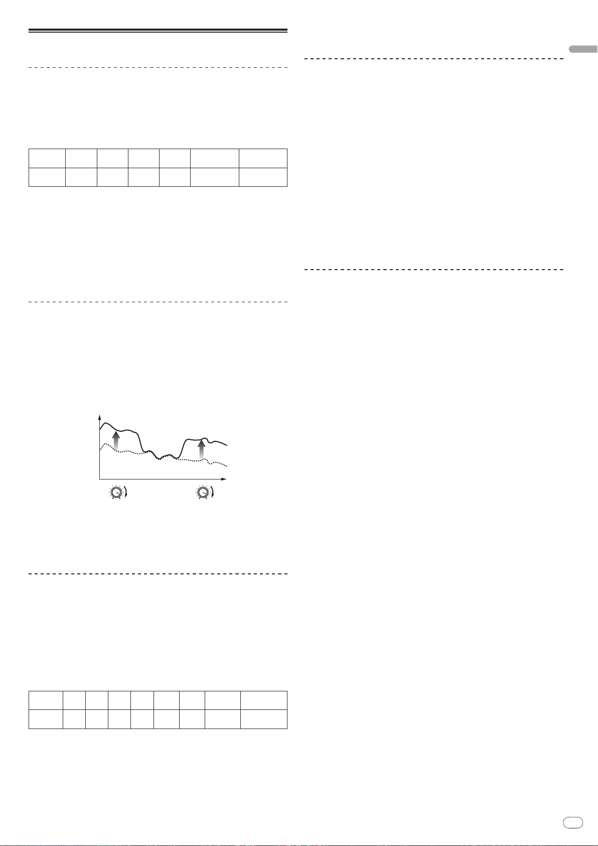
The world’s first 1, “Advanced Talkover” feature (page 14)
! This unit is equipped with the “Advanced Talkover” feature that makes the
sound from a microphone more listenable by automatically lowering the
volume in the frequency range of voice against music. The volume of music
is not affected by using a microphone, making it possible for you to continue
with an MC performance without hurting the atmosphere of the venue (the
music level can be adjusted with the knob on the control panel).
1 As of 8/
10/ 2009, for a DJ mixer, as determined by Pioneer.
PA Section
English
“MASTER/ ZONE Split Output” that makes individual
performances possible in 2 separate venues with only
one device (page 15)
! This unit is equipped with 2-channel output independently assigned to
MASTER output and ZONE output. You can output sound in separate channels to 2 venues, realizing a flexible party performance according to the atmosphere of each venue. Likewise, you can output sound from a microphone
to a selected destination, realizing an announcement or an MC performance
according to the atmosphere of each venue.
“SOUND MAXIMIZER” that can realize the sound setting
optimized for specific conditions or atmospheres (page 15)
! This unit is equipped with the “DYNAMICS” and “CLARITY” knobs used to
adjust the sound quality. You can generate a deep bass sound in the low-frequency range and a crispy clear sound in the mid- and high-frequency range,
which has never been possible with an equalizer. As you can easily adjust
the sound quality in the low- and high-frequency range, you can realize an
optimum sound setting according to the progress of a party. Also for a compressed sound format like MP3, the sound lost in the low- and high-frequency
range is reinforced.
What’s in the box
! Power cable
! USB Cable
! CD-ROM
! Operating instructions (this document)
DJ Section
A built-in “USB audio interface” that makes it possible to
input audio directly from a computer (page 8)
! This unit has a built-in “USB audio interface” that can input audio being
played back on a computer to a mixer via USB connection to the computer.
This makes it possible for you to realize a DJ performance using a computer
without an external sound card.
! You can mix up to 3-channel2 audio assigned each CH of DJM-5000 with only
one computer.
2 A CD-ROM with a driver software is supplied (compatible with Windows
and Mac). You can use the audio interface feature by installing the driver
software in your computer (For Windows, you can assign 3-channel audio
only when an ASIO-compatible software is used).
The “Assignable USB MIDI” feature that can control a
MIDI-compatible DJ software (page 10)
! This unit is equipped with the “Assignable USB MIDI” feature that can trans-
mit the operation information of almost all buttons and faders on DJM-5000
to a DJ software in MIDI signals via USB connection to a computer. You can
also use it as a MIDI controller with flexible operability.
Page 6
En
6
Connections
MASTER1
MASTER2
CH-4
ZONE
1 GND
1 GND
3 COLD
3 COLD
2 HOT
2 HOT
MASTER ATT.
-
12dB
-
6dB
0dB
-
12dB
-
6dB
0dB
ZONE ATT.
CD
L
L
L
L
RR
R
R
R
LINE
CH-3 CH-2 CH-1
DJM-
5000
CD CD
L
R
L
LINE
REC OUT
L
R
BOOTH
(TRS)
CONTROL
CD
R
L
CONTROL
SEND
L
(
MONO
)
R
L
(
MONO
)
R
L
R
RETURN
DIGITAL IN USB
21
MIC 3
MIC 2
1
6 72
3 3 4 4
4 4 5 5
16 141517 13 12 11 10
9 8
Be sure to turn off the power and unplug the power cord from the power outlet whenever making or changing connections.
Refer to the operating instructions for the component to be connected.
Connect the power cord after all the connections between devices have been completed.
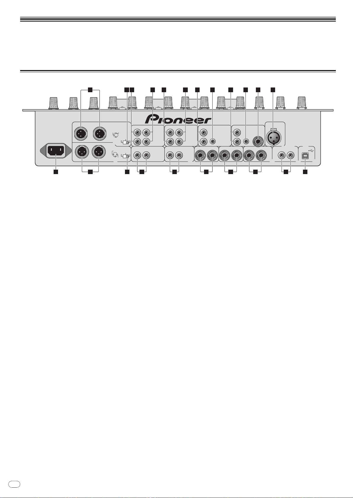
Rear Panel
1 ZONE (page 7)
An output terminal for the ZONE channel.
2 ZONE ATT
Use to switch the attenuation level of audio signals output at the [ZONE]
terminal. Select from 0 dB, -6 dB and -12 dB.
3 LINE (page 7)
Connect to a cassette deck or a line level output component.
4 CD (page 7)
Connect to a DJ player or a line level output component.
5 CONTROL (page 7)
This is a control terminal for a DJ player. Use the fader of this unit to control
a DJ player.
6 MIC3 (page 7)
Connect to a microphone.
7 MIC2 (page 7)
Connect to a microphone.
8 USB (page 8)
Connect to a computer.
9 DIGITAL IN (page 7)
Connect to a digital audio output component.
a RETURN (page 7)
Connect to the output terminal of an external effector. When the [L] channel
only is connected, the [L] channel input is simultaneously input to the [R]
channel.
b SEND (page 7)
Connect to the input terminal of an external effector. When the [L] channel
only is connected, a monaural audio signal is output.
c BOOTH (page 7)
Output terminals for a booth monitor, compatible with balanced or unbalanced output for a TRS connector.
d REC OUT (page 7)
This is an output terminal for recording.
e MASTER2 (page 7)
Connect to a power amplifier, etc.
f MASTER ATT
Use to switch the attenuation level of audio signals output at the [MASTER1]
or [MASTER2] terminal. Select from 0 dB, -6 dB and -12 dB.
g MASTER1 (page 7)
Connect to a power amplifier, etc.
h AC IN
Connect the supplied AC power cable to the AC IN inlet, then plug into a
power outlet. Plug in the power cable after all connections have been made.
Page 7
En
7
English
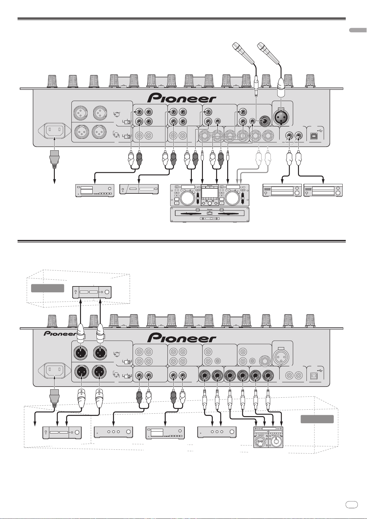
Connecting input terminals
MASTER1
MASTER2
CH-4
ZONE
1 GND
1 GND
3 COLD
3 COLD
2 HOT
2 HOT
MASTER ATT.
-
12dB
-
6dB
0dB
-
12dB
-
6dB
0dB
ZONE ATT.
CD
L
L
L
L
RR
R
R
R
LINE
CH-3 CH-2 CH-1
CD CD
L
R
L
LINE
REC OUT
L
R
CONTROL
CD
R
L
CONTROL
SEND
L
(
MONO
)
R
L
(
MONO
)
R
L
R
RETURN
DIGITAL IN USB
21
MIC 3
MIC 2
DJM-
5000
BOOTH
(TRS)
L
L
RR
L
L
RR
Pioneer DJ player
1
Microphone
To an AC outlet
Cassette deck, CD player, etc.
(a line level output device)
Digital audio output device
MASTER1
MASTER2
CH-4
ZONE
1 GND
1 GND
3 COLD
3 COLD
2 HOT
2 HOT
MASTER ATT.
-
12dB
-
6dB
0dB
-
12dB
-
6dB
0dB
ZONE ATT.
CD
L
L
L
L
RR
R
R
R
LINE
CH-3 CH-2 CH-1
CD CD
L
R
L
LINE
REC OUT
L
R
CONTROL
CD
R
L
CONTROL
SEND
L
(
MONO
)
R
L
(
MONO
)
R
L
R
RETURN
DIGITAL IN USB
21
MIC 3
MIC 2
DJM-
5000
BOOTH
(TRS)
R LR L
Power amplifier
2
Power amplifier
(for a booth monitor)
External effector
Cassette deck, etc.
(an analog input
recording device)
Power amplifierPower amplifier
Main room
Subroom
To an AC
outlet
1 Connect a control cable to use the fader start feature (page 13).
Connecting output terminals
2 A sound is output separately from the one in the master channel (MASTER/ ZONE split-out).
Page 8
En
8
PHONES
LEVEL
-
0
HEAD PHONES
NORMAL
ADVANCED
ON/OFF
TALK OVER
MIC1 ON
LEVEL
-
0
EFFECT
LOWHI
LOW
-
12 +12
MID
-
12 +12
HI
-
12 +12
OUTPUT
MASTER ZONE
BOTH
MIC 1 MIC 1
MIC2 ON
LEVEL
-
0
EFFECT
LOWHI
LOW
-
12 +12
MID
-
12 +12
HI
-
12 +12
OUTPUT
MASTER ZONE
BOTH
MIC 2
MINMAX
PITCHOCTAVER
ECHO+VERB
REVERB
MIC EFFECT
Microphone
Headphones
CH-1
CD
R
L
CONTROL
D
L
(
MONO
)
L
(
MONO
)
R
RETURN
DIGITAL IN USB
21
MIC 3
MIC 2
DJM-
5000
Computer
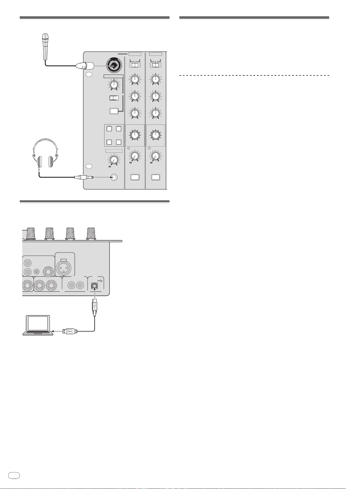
Connecting to the control panel
Connecting a computer
Connect with the supplied USB cable.
About the USB audio driver software
The driver software is an audio driver exclusively used to output audio signals
from a computer. If you would like to connect this unit to a Windows- or Macinstalled computer, we recommend you install the driver software in your computer first.
! You can find the latest information on the driver software on our website
(shown below).
http://www.prodjnet.com/support/
Software Use Agreement
This software usage agreement (hereafter referred to as “the agreement”) determines matters related to use of the DJ function software (hereafter referred to
as “the software”) between the customer and Pioneer Corporation (hereafter
referred to as “Pioneer”).
Be sure to read the following articles carefully before installing and using the
software. Use of the software implies that the customer has consented to the
agreement. If you do not consent to the agreement, do not install or use the
software.
[Usage agreement]
On the condition of complying with the contents of this agreement, the customer
has permission to install and use this software on a single personal computer.
[Restrictions]
The customer shall not create, distribute or send reproductions of this software
over networks or from one computer to another. In addition, the customer shall
not modify, sell, lend, transfer or resell the software, nor distribute, create, etc.,
secondary works of the software. Furthermore, the customer shall not reverse
compile, reverse engineer, reverse assemble or otherwise change the software
into formats perceptible by humans.
[Copyrights, etc.]
Copyrights and all other intellectual property rights related to this software are
the property of Pioneer and its affiliates. This software is protected by copyright
laws and the provisions of international treaties.
[Repudiation of guarantee and technical support]
This software and all associated documentation, etc., is provided on an “as is”
basis. Pioneer does not guarantee the customer nor third parties regarding
merchantability, compatibility with specific purposes, violation of rights of others or any other matters, nor does it guarantee technical support related to this
software or associated documentation. Note that repudiation of guarantee may
not be not recognized in some countries and regions by mandatory provisions, in
which case this repudiation of guarantee may not apply. The customer’s rights
may differ in some countries and regions.
[Limitation of liability]
Pioneer and other suppliers of this software shall accept no responsibility
whatsoever for damages incurred through use of or inability to use this software
or any associated documentation (including but not limited to loss of profits,
business interruptions, damages resulting from loss or impairment of information, etc.), even if Pioneer has been notified of the possibility of such damages.
Limitation of liability related to incidental or direct damages may not be recognized in some countries and regions by mandatory provisions, in which case this
limitation of liability may not apply. Note that, regardless of the case, the responsibility of Pioneer and its subsidiaries regarding this software shall not exceed
the sum paid by the customer to Pioneer or its subsidiaries. This repudiation of
limitation of liability is a fundamental element of the arrangement between the
customer and Pioneer.
[Governing law]
This agreement complies with the laws and ordinances of Japan and shall be
interpreted accordingly. This agreement stipulates all articles of the arrangement
between the customer and Pioneer, and shall be applied with priority over any
prior and existing agreements related to this matter (regardless of whether oral
or in writing). The Tokyo District Court shall be the court of exclusive jurisdiction
in first instance for any disputes arising regarding this agreement.
Page 9

En
9
English
Cautions on Installation
! Before installing the driver software, be sure to turn off the power of this unit
and disconnect the USB cable from both this unit and your computer.
! If you connect this unit to your computer without installing the driver soft-
ware first, an error may occur on your computer depending on the system
environment.
! If you have discontinued the installation process in progress, step through
the installation process again from the beginning according to the following
procedure.
! Carefully read the provisions of the Software Use Agreement before installing
the driver software for exclusive use with this unit.
! Before installing the driver software, terminate all other programs running on
your computer.
! The driver software is compatible with the following OSs.
— Mac OS X (10.3.9 and later)
— Windows Vista
— Windows® XP Home Edition/ Professional (SP2 or later)
The driver software is not compatible with 64-bit OS (Windows® XP
Professional x64 edition and Windows Vista® 64-bit).
! The CD-ROM with the driver software includes an installer running in the fol-
lowing 12 languages.
English, French, German, Italian, Dutch, Spanish, Portuguese, Russian,
Simplified Chinese, Traditional Chinese, Korean, and Japanese
If the language of your OS is one other than the ones listed above, select
[English] following the instructions on the screen.
®
Home Basic/ HomePremium/ Ultimate/ Business
Installing the driver software
Installation Procedure (Windows)
Carefully read “Cautions on Installation” before installing the driver software.
! To install or uninstall the driver software, you need to be authorized by the
administrator of your computer. Log in as the administrator of your computer
before proceeding with the installation.
1 Insert the supplied CD-ROM into the CD drive of your
computer
The CD-ROM folder appears.
! If the CD-ROM folder is not displayed after a CD-ROM is loaded, open the CD
drive from [Computer (or My Computer)] in the [START] menu.
2 Double-click [DJM-5000_X.XXX.exe]
The driver installation screen appears.
3 When the language selection screen appears, select [English]
and click [OK]
You can select one from multiple languages depending on the system environment of your computer.
4 Carefully read the Software Use Agreement and if you consent to
the provisions, put a check mark in [I agree.] and click [OK]
If you do not consent to the provisions of the Software Use Agreement, click
[Cancel] and stop installation.
5 Proceed with installation according to the instructions on the
screen
If [Windows Security] appears on the screen while the installation is in progress,
click [Install this driver software anyway] and continue with the installation.
! When installing on Windows XP
If [Hardware Installation] appears on the screen while the installation is in
progress, click [Continue Anyway] and continue with the installation.
! When the installation program is completed, a completion message appears.
! When the installation of the driver software is completed, you need to reboot
your computer.
Installation Procedure (Macintosh)
Carefully read “Cautions on Installation” before installing the driver software.
! To install or uninstall the driver software, you need to be authorized by the
administrator of your computer. Have the name and password of the administrator of your computer ready in advance.
1 Insert the supplied CD-ROM into the CD drive of your
computer
The CD-ROM folder appears.
! Double-click the CD icon on the desktop when folders are not displayed after
a CD-ROM has been loaded.
2 Double-click [DJM-5000_M_X.X.X.dmg]
The [DJM-5000AudioDriver] menu screen appears.
3 Double-click [DJM-5000AudioDriver.pkg]
The driver installation screen appears.
4 Check the details on the screen and click [Continue Anyway]
5 When the Software Use Agreement screen appears, select
[English], carefully read the Software Use Agreement and click
[Continue Anyway]
You can select one from multiple languages depending on the system environment of your computer.
6 If you consent to the provisions of the Software End User
License Agreement, click [Agree]
If you do not consent to the provisions of the Software Use Agreement, click [I
disagree] and stop installation.
7 Proceed with installation according to the instructions on the
screen
! To stop installation in progress, click [Cancel].
! When the installation of the driver software is completed, you need to reboot
your computer.
Connecting the DJM-5000 and computer
1 Connect this unit to your computer via a USB cable
This unit functions as an audio device conforming to the ASIO standards.
! When using applications supporting ASIO, [USB 1/ 2], [USB 3/ 4] and
[USB 5/ 6] can be used as inputs.
! When using applications supporting DirectX, only [USB 5/ 6] can be used as
the input.
! The computer’s recommended operating environment depends on the DJ
application. Be sure to check the recommended operating environment for
the DJ application you are using.
2 Press [POWER]
Turn on the power of this unit.
! The message [Installing device driver software] may appear when the DJM-
5000 is connected to the computer for the first time or when it is reconnected
to the computer’s USB port. Wait until the [Your devices are ready for use]
message appears.
! When installing on Windows XP
— [Can Windows connect to Windows Update to search for software?]
may appear while the installation is in progress. Select [No, not this
time] and click [Next] to continue with the installation.
— [What do you want the wizard to do?] may appear while the instal-
lation is in progress. Select [Install the software automatically
(Recommended)] and click [Next] to continue with the installation.
— If [Windows Security] appears on the screen while the installation is in
progress, click [Install this driver software anyway] and continue with
the installation.
Page 10
En
10
Adjusting the buffer size (Windows)
dB
14
9
5
2
0
–2
–4
–7
–10
–15
LR
Use this procedure to adjust the computer’s buffer size when using an ASIO
audio driver.
Click Windows [START] menu >[View All
Program]>[Pioneer]>[DJM-5000]>[DJM-5000 ASIO Settings Utility]
A sufficiently large buffer size decreases the chance of sound dropout (sound
interruption) but increases audio signal transmission delay (latency).
! When an application program (DJ software, etc.) with this unit set as a fixed
device is running, terminate the program before adjusting the buffer size.
Checking the version of the driver software
Procedure for checking (Windows)
Click Windows [START] menu >[View All
Program]>[Pioneer]>[DJM-5000]>[DJM-5000 Version Display
Utility]
The [Version] screen appears.
Procedure for checking (Macintosh)
Click [Apple]>[About This Mac]>[More Info]>[Extensions]>[DJM5000 USBAudio].
The [Version] screen appears.
Checking the latest information on the driver
software
For the latest information on the driver software for exclusive use with this unit,
visit our website shown below.
http://www.prodjnet.com/support/
About USB-MIDI channel setting
Turn off the power of this unit in advance.
1 Set [MIDI] to [ON]
2 Press and hold [FADER START] for [CH-1] and [CH-2]
simultaneously and press [POWER]
When the MASTER [CUE] and ZONE [CUE] buttons light orange, the MIDI channel
setting mode is set. Press and hold in [FADER START] for [CH-1] and [CH-2] until
the buttons light orange.
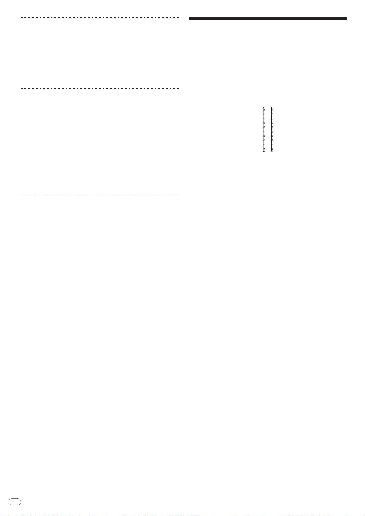
! The current MIDI channel setting is displayed in the master level indicator.
[L] shows the position of 10, while [R] the position of 1.
! The MIDI channel is initially set to [1].
Example: to show 16
3 Press [CUE] in the [MASTER] channel
The MIDI channel changes by one channel each time you press it.
Select a MIDI channel to change the setting.
4 Press and hold [CUE] for the [ZONE] channel
Save the changes made for the MIDI channel.
While settings are being saved, [ON/ OFF] flashes for the [SOUND MAXIMIZER]
channel. Lights up when the saving is completed.
! Do not turn off the power while saving MIDI channel settings.
5 Press [POWER]
Turn off the power of this unit.
6 Press [POWER]
Turn on the power of this unit again.
Start in the normal mode. The MIDI channel setting is changed.
Page 11
En
11
English
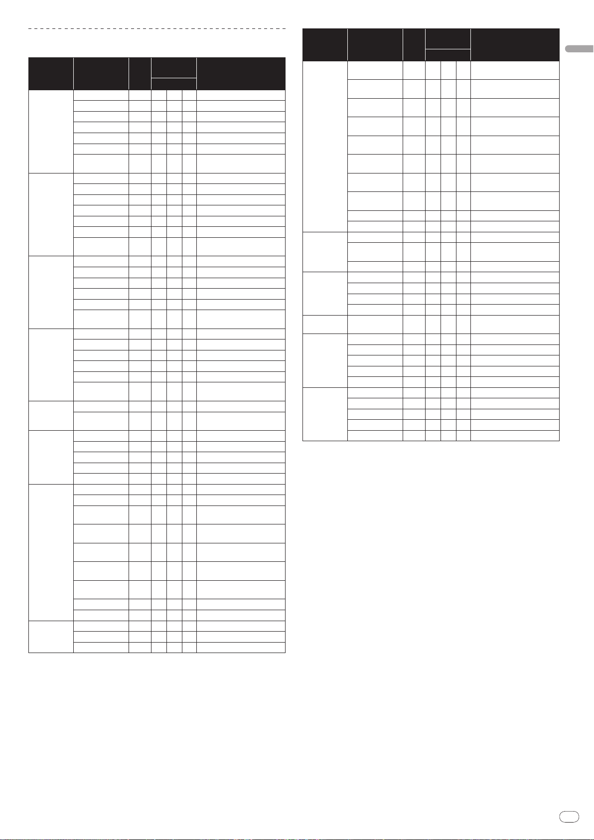
List of MIDI Messages
Category SW Name
HI
MID
LOW
CH-1
CH-2
CH-3
CH-4
CROSS FADER
MASTER
ZONE
SOUND
MAXIMIZER
FADER START
CUE
Channel fader VR Bn 11 dd 0-127
Crossfader
Assign Switch
HI
MID
LOW
FADER START
CUE
Channel fader VR Bn 12 dd 0-127
Crossfader
Assign Switch
HI
MID
LOW
CUE
Channel fader VR Bn 13 dd 0-127
Crossfader
Assign Switch
HI
MID
LOW
CUE
Channel fader VR Bn 14 dd 0-127
Crossfader
Assign Switch
Crossfader VR Bn 0B dd 0-127
CROSS FADER
LEVEL
CUE
BALANCE
STEREO SW Bn 60 dd MONO=0, STEREO=127
MONO/
BOOTH MONITOR
LEVEL
CUE
ZONE ASSIGN
CH-1
ZONE ASSIGN
CH-2
ZONE ASSIGN
CH-3
ZONE ASSIGN
CH-4
ZONE ASSIGN
MASTER
ZONE ASSIGN OFF
OFF BTN Bn 63 dd OFF=0, ON=127
ON/
CLARITY
DYNAMICS
OFF BTN Bn 4E dd OFF=0, ON=127
ON/
SW
Type
VR Bn 2 dd 0-127
VR Bn 3 dd 0-127
VR Bn 4 dd 0-127
BTN Bn 58 dd OFF=0, ON=127
BTN Bn 46 dd OFF=0, ON=127
SW Bn 41 dd A=0, THRU=64, B=127
VR Bn 7 dd 0-127
VR Bn 8 dd 0-127
VR Bn 9 dd 0-127
BTN Bn 59 dd OFF=0, ON=127
BTN Bn 47 dd OFF=0, ON=127
SW Bn 42 dd A=0, THRU=64, B=127
VR Bn OE dd 0-127
VR Bn OF dd 0-127
VR Bn 15 dd 0-127
BTN Bn 48 dd OFF=0, ON=127
SW Bn 43 dd A=0, THRU=64, B=127
VR Bn 51 dd 0-127
VR Bn 5C dd 0-127
VR Bn 52 dd 0-127
BTN Bn 49 dd OFF=0, ON=127
SW Bn 44 dd A=0, THRU=64, B=127
SW Bn 5F dd
VR Bn 18 dd 0-127
BTN Bn 4A dd OFF=0, ON=127
VR Bn 17 dd 0-127
VR Bn 19 dd 0-127
VR Bn 61 dd 0-127
BTN Bn 62 dd OFF=0, ON=127
SW Bn 20 dd 127
SW Bn 21 dd 127
SW Bn 22 dd 127
SW Bn 23 dd 127
SW Bn 24 dd 127
SW Bn 25 dd 127
VR Bn 64 dd 0-127
VR Bn 65 dd 0-127
MIDI
Messages
MSB
Notes
Left=0, Middle=64,
Right=127
MIDI
SW
Category SW Name
SEND/
RETURN
CH-1
RETURN
SEND/
CH-2
RETURN
SEND/
CH-3
RETURN
SEND/
CH-4
RETURN
SEND/
RETURN
TALK OVER
MIC EFFECT
HEAD
PHONES
MIC 1
MIC 2
! MIDI ON/
! “n” in the MIDI message “Bn” is a value of the MIDI channel set by the user, ranging
from 0x00 to 0x0F (1 to 16 on the setting screen)
SEND/
MIC 1
RETURN
SEND/
MIC 2
RETURN
SEND/
MIC 1+2
RETURN
SEND/
MASTER
LEVEL
OFF VR Bn 40 dd OFF=0, ON=127
ON/
LEVEL
NORMAL/
ADVANCED
OFF BTN Bn 69 dd OFF=0, ON=127
ON/
REVERB
ECHO+VERB
OCTAVER
PITCH
LEVEL
HI
MID
LOW
EFFECT
MIC1 ON
HI
MID
LOW
EFFECT
MIC2 ON
OFF controls whether to transmit MIDI messages.
Messages
Type
MSB
SW Bn 30 dd 127
SW Bn 31 dd 127
SW Bn 32 dd 127
SW Bn 33 dd 127
SW Bn 34 dd 127
SW Bn 35 dd 127
SW Bn 36 dd 127
SW Bn 37 dd 127
VR Bn 66 dd 0-127
VR Bn 67 dd 0-127
SW Bn 68 dd
BTN Bn 6A dd OFF=0, ON=127
BTN Bn 6B dd OFF=0, ON=127
BTN Bn 6C dd OFF=0, ON=127
BTN Bn 6D dd OFF=0, ON=127
VR Bn 1A dd 0-127
VR Bn 1E dd 0-127
VR Bn 6E dd 0-127
VR Bn 1F dd 0-127
VR Bn 70 dd 0-127
BTN Bn 71 dd OFF=0, ON=127
VR Bn 72 dd 0-127
VR Bn 73 dd 0-127
VR Bn 74 dd 0-127
VR Bn 75 dd 0-127
BTN Bn 76 dd OFF=0, ON=127
Notes
NORMAL=0,
ADVANCED=127
Page 12
En
12
Operations
DJM-
5000
PROFESSIONAL MIXER
PHONES
LEVEL
-
0
HEAD PHONES
PITCHOCTAVER
ECHO+VERB
REVERB
MIC EFFECT
NORMAL
ADVANCED
ON/OFF
TALK OVER
MIN MAX
MIC1 ON
LEVEL
-
0
EFFECT
LOWHI
LOW
-
12 +12
MID
-
12 +12
HI
-
12 +12
OUTPUT
MASTER ZONE
BOTH
MIC 1 MIC 1
MIC2 ON
LEVEL
-
0
EFFECT
LOWHI
LOW
-
12 +12
MID
-
12 +12
HI
-
12 +12
OUTPUT
MASTER ZONE
BOTH
MIC 2
ABTHRU
CH -1
LOW
-
26
+6
MID
-
26
+6
HI
-
26
+6
CUE
FADER
START
TRIM
-
+9
CD
MIC 3
DIGITAL1
dB
14
9
5
2
0
–2
–4
–7
–10
–15
ABTHRU
CH -2
LOW
-
26
+6
MID
-
26
+6
HI
-
26
+6
CUE
FADER
START
TRIM
-
+9
CD
USB 1/2
DIGITAL2
dB
14
9
5
2
0
–2
–4
–7
–10
–15
ABTHRU
CH -3
LOW
-
26
+6
MID
-
26
+6
HI
-
26
+6
CUE
TRIM
-
+9
CD
USB 3/4
LINE
dB
14
9
5
2
0
–2
–4
–7
–10
–15
ABTHRU
CH -4
LOW
-
26
+6
MID
-
26
+6
HI
-
26
+6
CUE
TRIM
-
+9
CD
USB 5/6
LINE
dB
14
9
5
2
0
–2
–4
–7
–10
–15
OFFON
MIDI
CROSS
FADER
BOOTH MONITOR
-
0
STEREOMONO
BALANCE
L
R
CUE
dB
14
9
5
2
0
–2
–4
–7
–10
–15
LR
LEVEL
-
0
MASTER
ZONE ON
CUE
1
2
34
MASTER
MIC
dB
14
9
5
2
0
–2
–4
–7
–10
–15
LEVEL
-
0
ZONE
ZONE ASSIGN
POWER
SOUND
MAXIMIZER
DYNAMICS
MINMAX
CLARITY
MINMAX
ON/OFF
1
2
3
4
MIC1
MIC2
MIC1+2
MASTER
SEND/RETURN
LEVEL
MINMAX
ON/OFF
MC Section DJ Section PA Section
7
b
5
1
3
2
8
9
a
4
7
6
665
1
3
2
8
4
7
65
5
1
2
8
7
8
4
1
2
4
2
3
4
6
8
7
1
9
a
5
b
c
d
1
2
4
3
5
6
9
7
8
a
b
i
c
d
e
f
g
h
MIC 1
MIC 2
TALK OVER
HEAD PHONES
CH-1
CH-4
CROSS FADER
MIDI
MASTER
ZONE
SOUND MAXIMIZER
SEND/ RETURN
POWER
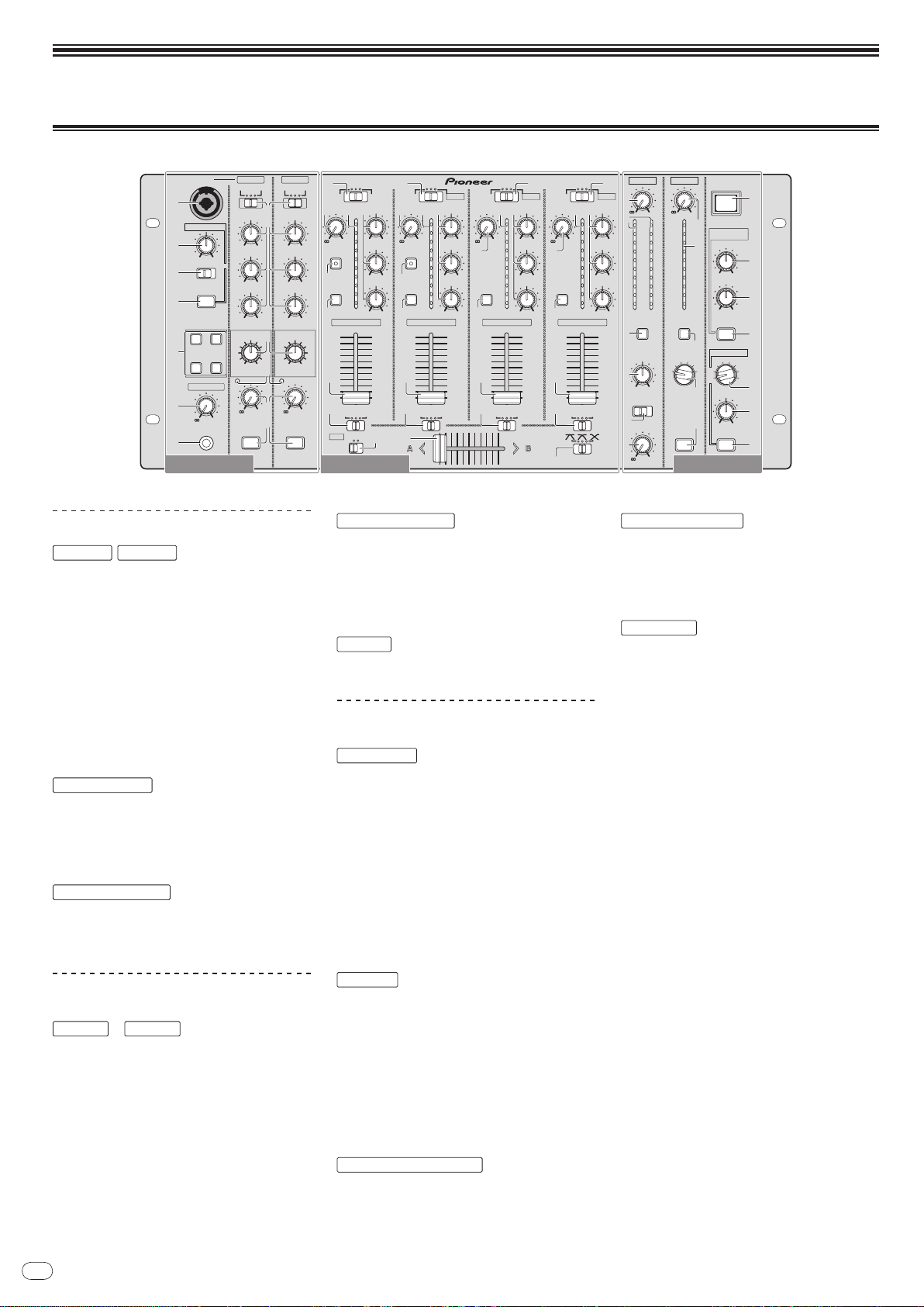
Control Panel
MC Section
,
1 MIC 1 (page 14)
2 OUTPUT (page 14)
3 HI, MID, LOW (page 14)
4 EFFECT (page 14)
5 MIC EFFECT (page 14)
6 Peak Level Indicator (page 14)
7 LEVEL (page 14)
8 MIC1 ON, MIC2 ON (page 14)
8 Crossfader Assign Switch (page 13)
9 Crossfader (page 13)
a [CROSS FADER] (Crossfader Curve
Selector Switch) (page 13)
b MIDI (page 13)
PA Section
f Output Channel Selector Switch (page 15)
g LEVEL (page 15)
h ON/
OFF (page 15)
i POWER (page 13)
1 LEVEL (page 13)
9 Talk-Over Level (page 14)
a NORMAL/
b ON/
ADVANCED (page 14)
OFF (page 14)
2 Master Level Indicator (page 13)
Displays the level of audio signals that have
passed through [LEVEL] in the [MASTER]
channel.
3 CUE (page 13)
4 BALANCE (page 15)
c LEVEL (page 13)
d PHONES (page 13)
5 MONO/
6 BOOTH MONITOR (page 15)
STEREO (page 15)
DJ Section
1 Input Selector Switch (page 13)
2 TRIM (page 13)
3 FADER START (page 13)
4 CUE (page 13)
5 Channel Level Indicator (page 13)
6 HI, MID, LOW (page 13)
7 Channel Fader (page 13)
—
7 LEVEL (page 15)
8 Zone Level Indicator (page 15)
9 CUE (page 13)
a Output Channel Selector Switch (page 15)
b ZONE ON (page 15)
Displays the level of audio signals that have
passed through [LEVEL] in the [ZONE] channel.
c CLARITY (page 15)
d DYNAMICS (page 15)
e ON/
OFF (page 15)
Page 13
En
13
English
Operating the DJ section
ON
OFF
OFF
ON
ON
OFF
ON
OFF
ON
OFF
ON
OFF
ON
ON
OFF
OFF
ON
OFF
ON
ON
ON
CH (L)
MASTER (L)
ZONE (L)
CH (MONO)
CH (MONO)
MASTER (L)+ZONE (L)
CH (MONO)
CH (R)
MASTER (R)
ZONE (R)
MASTER (MONO)
ZONE (MONO)
MASTER (R)+ZONE (R)
MASTER (MONO)
+ZONE (MONO)
CH-1
‒
CH-4
MASTER ZONE
Headphone Output
L channel
R channel
Outputting sound
1 Press [POWER]
Turn on the power of this unit.
2 Set the input selector switch
Select the input source of each channel from the components connected to this
unit.
! To output sound of the computer connected to the [USB] terminal, switch the
input selector switch for [CH-2], [CH-3], and [CH-4] to [USB].
3 Rotate [TRIM]
Adjusts the level of audio signals input in each channel.
! The channel level indicator lights when the sound is being properly input to
the channel.
4 Set the channel fader to the inner position
Adjusts the level of audio signals output in each channel.
5 Adjust the crossfader assign switch
Switches the output destination of each channel.
— [A]: Assigns to [A] (left) of the crossfader.
— [B]: Assigns to [B] (right) of the crossfader.
— [THRU]: Assigns to the [MASTER] channel (the crossfader is not passed
through).
6 Adjust the crossfader curve switch ([CROSS FADER])
Switches the crossfader curve characteristics.
— [ ]: Makes a sharply increasing curve (if the crossfader is moved away
from the [A] side, audio signals are immediately output from the [B]
side).
— [ ]: Makes a curve shaped between the two curves above and below.
— [ ]: Makes a gradually increasing curve (if the crossfader is moved
away from the [A] side, the sound on the [B] side gradually increases,
while the sound on the [A] gradually decreases).
7 Set the crossfader
Outputs audio signals assigned by the crossfader assign switch corresponding to
the curve characteristics selected by [CROSS FADER] (Crossfader Curve Selector
Switch).
! You do not need to follow this step when the crossfader assign switch is set to
[THRU].
8 Rotate [LEVEL] for the [MASTER] channel
The sound is output from [MASTER1] and [MASTER2]. The master level indicator
lights.
Adjusting the sound quality
Rotate [HI], [MID] or [LOW] in each channel
Refer to Specifications on page 18 for the range of sound that can be adjusted by
each control.
Monitoring sound with headphones
1 Connect headphones to the [PHONES] jack
2 Press [CUE] for the channel to be monitored
The button lights up brightly in orange.
3 Turn the [LEVEL] dial for [HEAD PHONES]
Sound is output from the headphones in the channel selected by [CUE].
! Sound output from the headphones varies according to the combination of
channels selected by [CUE]. See the table below.
Using the fader to play a Pioneer DJ player
(fader start)
If you connect a Pioneer DJ player using a control cable (supplied with a DJ
player), you can start playback of control other operations of the DJ player with
the fader of this unit.
The fader start feature is available only when a Pioneer DJ player is connected to
[CH-1] or [CH-2].
Connect a Pioneer DJ player to this unit in advance (page 7).
Start playback using the channel fader
1 Set the crossfader assign switch to [THRU]
2 Press [FADER START]
Turn on the fader start function. The button lights up brightly in orange.
3 Set the channel fader to the outermost position
4 Set the cue on the DJ player
The DJ player pauses playback at the cue point.
5 Set the channel fader to the inner position
Playback starts on the DJ player.
! If you set the channel fader back to the original position, the player instanta-
neously returns to the cue point already set and pauses playback (back cue).
Start playback using the crossfader
1 Set the crossfader assign switch to [A] or [B]
2 Press [FADER START]
Turn on the fader start function. The button lights up brightly in orange.
3 Set the crossfader
Set to the farmost end in the opposite direction to the channel to be fader started.
4 Set the cue on the DJ player
The DJ player pauses playback at the cue point.
5 Set the crossfader
Playback starts on the DJ player.
! If you set the crossfader back to the original position, the player instanta-
neously returns to the cue point already set and pauses playback (back cue).
Operating the DJ software
The DJM-5000 also outputs the operating data for the buttons and dials in MIDI
format. If you connect a computer with a built-in MIDI-compatible DJ software
via a USB cable, you can operate the DJ software on this unit.
Install the DJ software on your computer in advance. Also, adjust audio and MIDI
settings for the DJ software.
1 Connect the USB port on this unit to your computer
For details about connections, see Connecting a computer on page 8.
2 Start the DJ software
3 Set [MIDI] to [ON]
Transmission of the MIDI messages begin.
! You can send MIDI messages altogether according to the position of buttons,
faders, or control knobs (snapshot).
! Adjust faders and control knobs to transmit messages based on the corre-
sponding position. For details about the messages generated by this unit, see
List of MIDI Messages on page 11.
4 Set [MIDI] to [OFF]
The MIDI messages are not transmitted even if you operate this unit.
! Monitoring is canceled if you press [CUE] again. The button lights up dimly in
orange.
Page 14
En
14
Operating the MC section
dB
Frequency
NORMAL
ADVANCED
dB
Frequency
NORMAL
ADVANCED
Using a microphone
1 Switch [OUTPUT]
Select the output destination of the sound output from the [MIC1] or [MIC2]
channel.
2 Rotate [LEVEL] for the microphone channel
Adjusts the level of audio signals output from the microphone channel.
! Pay attention that rotating to the extreme right position outputs a very loud
sound.
3 Press [MIC1 ON] for the [MIC1] channel or [MIC2 ON] for the
[MIC2] channel.
Turn on the microphone channel. The button lights up in green.
4 Input audio signals to the microphone
Sound is output to the output destination selected in step 1.
! The peak level indicator lights in different colors corresponding to the level of
audio being input.
— Green: Permissible level
— Orange: Appropriate level
— Red: Excessive level (lower the level of audio by rotating [LEVEL] to the
left)
Adjusting the sound quality
Rotate [HI], [MID] or [LOW] for the [MIC1] or [MIC2] channel
Refer to Specifications on page 18 for the range of sound that can be adjusted by
each control.
Using the microphone effect feature
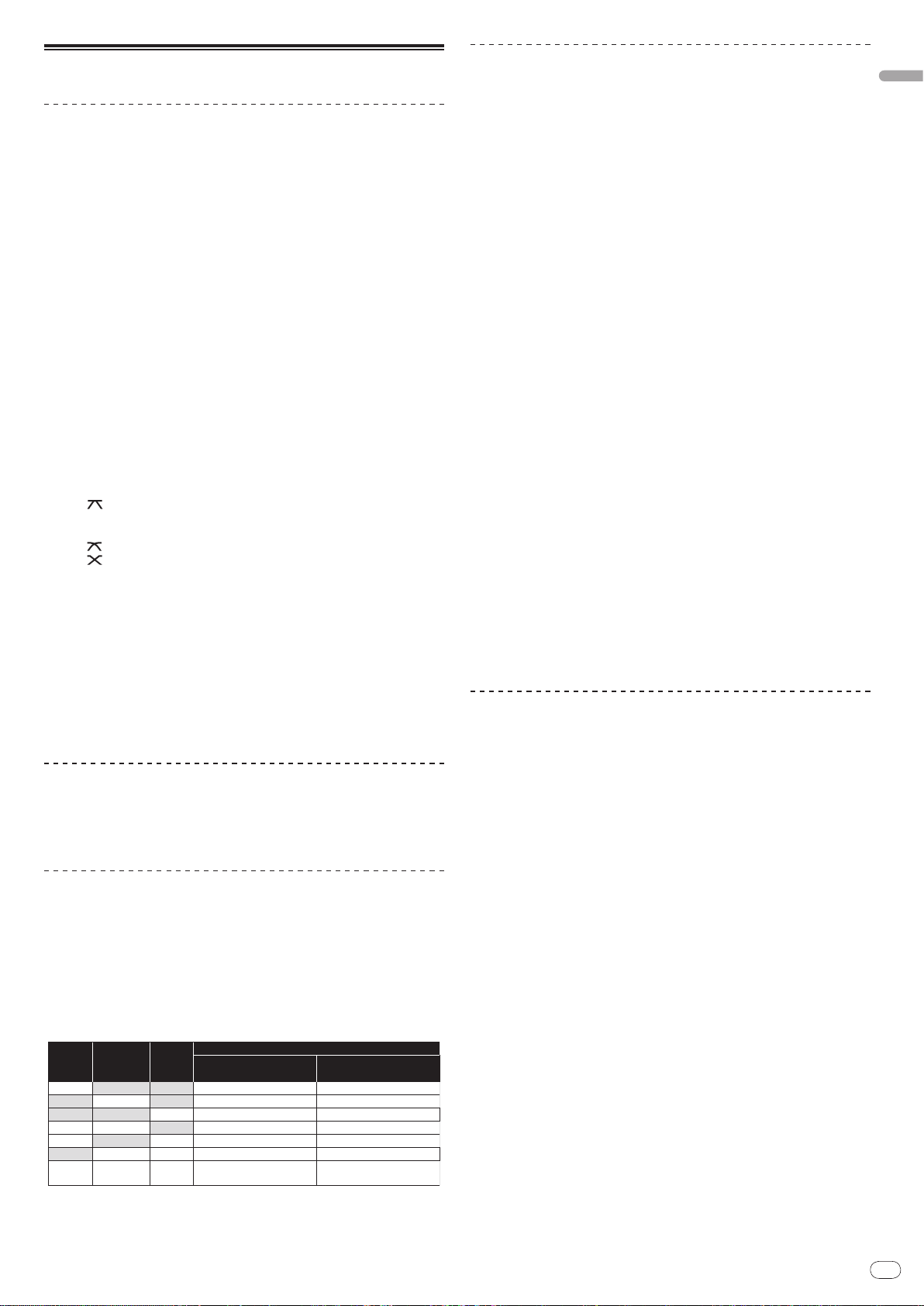
Using the talk-over feature
1 Rotate the talk-over level
Set the attenuation level of sound besides the one in the microphone channel.
2 Switch between [NORMAL]/ [ADVANCED]
The attenuation mode for the talk-over function switches.
! Normal talk over:
The sound output from channels other than the microphone channel is
attenuated by the amount set for the talk over level.
! Advanced talk over:
Only the voice band of the sound output from channels other than the
microphone channel is attenuated by the amount set for the talk over
level.
3 Press [ON/ OFF] for [TALK OVER]
Turn on the talk-over function. The button lights up in red.
! When audio signals are input in the microphone channel, the sound, besides
the one in the microphone channel, is attenuated according to the attenuation mode setting and the position of the control.
1 Press [MIC EFFECT (REVERB, ECHO+VERB, OCTAVER or PITCH)]
Turn on the microphone effect function. The button flashes in blue.
! The effect varies depending on the button.
2 Rotate [EFFECT]
Adds an effect to the sound output from the microphone channel.
! The effect varies according to the rotation direction and position of [EFFECT].
Effect Name Descriptions
1
REVERB
ECHO+VERB
1
OCTAVER
PITCH
1 The more you rotate it to the right, the louder the effect sound.
! When you turn off the microphone effect function, press the flashing
[MIC EFFECT (REVERB, ECHO+VERB, OCTAVER, PITCH)] once again. The button lights up in blue.
Adds a reverberation effect to the original sound.
1
Adds reverberation and echo effects to the original sound.
Adds sound with 1 octave up and down to the original sound.
Changes the musical interval within the range of 1 octave up and
down. Rotate it to the right and left to change the interval 1 octave up
and down respectively.
Page 15
En
15
English
Operating the PA section
dB
Frequency
DYNAMICS
MINMAX
CLARITY
MINMAX
! To stop the sound output at the [SEND] terminal, press the flashing [ON/ OFF].
The button lights up.
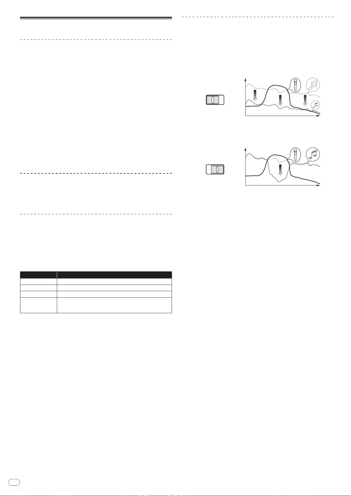
Outputting sound from the ZONE terminal
You can output sound from the [ZONE] terminal besides the sound output from
the master channel.
1 Set the output channel selector switch for the [ZONE] channel
Select the channel output from the [ZONE] terminal.
! Sound output varies according to the position of the switch.
Switch
Position
Audio
Output
1 Audio is output regardless of the position of faders and control knobs.
2 Audio is output regardless of the position of [LEVEL] for the [MASTER] channel.
3 Audio is output only from the microphone channel, for which [OUTPUT] is set to [BOTH]
1 2 3 4 MASTER MIC
1
Microphone
Channel
or [ZONE].
CH-1
1
CH-21CH-31CH-4
2
Microphone
3
Channel
2 Press [ZONE ON] for the [ZONE] channel
Turn on the [ZONE] channel. The button lights up in green.
3 Rotate [LEVEL] for the [ZONE] channel
Sound is output at the [ZONE] terminal. The zone level indicator lights up.
! To turn the [ZONE] channel off, press [ZONE ON] again. The button turns off.
Using the sound maximizer feature
1 Press [ON/ OFF] for [SOUND MAXIMIZER]
Turn on the sound maximizer function. The button lights up in blue.
2 Rotate [CLARITY] or [DYNAMICS]
The effect of the sound maximizer varies according to the rotation direction and
position of the control.
! The output audio level increases according to the sound maximizer effect
when the dial is turned clockwise. Pay attention to the output audio level
when using the sound maximizer function.
Switching between monaural and stereo audio
You can switch between monaural and stereo audio for the sound output at the
[MASTER1], [MASTER2], [BOOTH], [REC OUT] or [PHONES] terminal.
Switch between [MONO]/ [STEREO]
! [MONO]: Outputs monaural audio.
! [STEREO]: Outputs stereo audio.
Adjusting the L/ R balance of audio
The left/ right balance of the sound output from the [MASTER1], [MASTER2],
[BOOTH], [REC OUT] and [PHONES] terminals can be adjusted.
1 Set [MONO]/ [STEREO] to [STEREO]
2 Rotate [BALANCE]
The L/ R balance of audio varies according to the rotation direction and position
of the [BALANCE] control.
! Rotating to the rightmost position outputs only the right sound of stereo
audio. Rotating to the leftmost position outputs only the left sound of stereo
audio.
Audio is output from the [BOOTH] terminal
The master channel audio, except the microphone channel audio, is output from
the [BOOTH] terminal regardless of the position of [LEVEL] in the [MASTER]
channel.
Rotate [BOOTH MONITOR]
Adjusts the level of audio signals output at the [BOOTH] terminal.
! The range of sound that can be adjusted varies according to the control.
— CLARITY: Adjusts the attack and outline of sound mainly in the mid and
high range (high hat, snare, etc.).
— DYNAMICS: Adjusts modulation and rhythm mainly in the low range.
! When you turn off the sound maximizer function, press [ON/ OFF] again. The
light of the button turns off.
Using the external effector
1 Connect the external effector
[ON/ OFF] of [SEND/ RETURN] lights up in red. When the external effector is not
connected, [ON/ OFF] does not light up.
! For details about connections, see Connections on page 6.
2 Set the output channel selector switch for the [SEND/ RETURN]
channel
Select the channel output from the [SEND] terminal.
! Sound output varies according to the position of the switch.
Switch
Position
Audio
Output
1 The microphone sound output from the master channel is output from the [SEND] chan-
3 Press [ON/ OFF] for [SEND/ RETURN]
Sound is output at the [SEND] terminal. The button flashes in red.
4 Turn the [LEVEL] dial for [SEND/ RETURN]
Adjusts the level of audio signals input at the [RETURN] terminal.
1 2 3 4 MIC 1 MIC 2 MIC1+2 MASTER
CH-1 CH-2 CH-3 CH-4 MIC 1 MIC 2
nel.
MIC1+2
1
Master Channel
Page 16
En
16
Additional information
Troubleshooting
! Incorrect operation is often mistaken for trouble or malfunction. If you think that there is something wrong with this component, check the points below. Sometimes
the trouble may lie in another component. Inspect the other components and electrical appliances being used. If the trouble cannot be rectified after checking the
items below, ask your nearest Pioneer authorized service center or your dealer to carry out repair work.
! The player may not operate properly due to static electricity or other external influences. In such cases, normal operation may be restored by unplugging the power
cord then plugging it back in.
Problem Check Remedy
The power is not turned on. Is the power cord properly connected? Plug in the power cord to an AC outlet.
No sound or small sound. Is the position of the input selector switch properly set? Switch the input source of a channel with the input selector switch (page
Are the connection cables properly connected? Connect the connection cables properly (page 7).
Are the terminals and plugs dirty? Clean the terminals and plugs before making connections.
Is [MASTER ATT] on the rear panel set to a level like -12 dB?
Distorted sound. Is the level of audio output from the microphone channel
Can’t crossfade. Is the crossfader assign switch properly set? Set the crossfader assign switch properly for each channel (page 12).
Can’t fader start a DJ player. Is [FADER START] set to off? Set [FADER START] to on (page 13).
No effect. Is [EFFECT] set to a proper position? Set [EFFECT] to a position other than [LOW] (page 12).
Can’t use an external effector. Is [SEND/
Distorted sound from an external effector. Is the level of audio input from the external effector prop-
This unit is not recognized after it has been connected
to a computer.
properly set?
Is the level of audio input to each channel properly set? Adjust the [TRIM] control such that the channel level indicator lights up
Is the DJ player properly connected to the [CONTROL]
terminal?
Are the audio cables properly connected? Connect this unit to the audio output terminal of a DJ player with an audio
RETURN] [ON/ OFF] set to on? Press [ON/ OFF] of [SEND/ RETURN] to turn on [SEND/ RETURN] (page 12).
Is the external effector properly connected to the [SEND]
or [RETURN] terminal?
Is the output channel switch of [SEND/
set?
erly set?
Is the driver software properly installed on your computer? Install the driver software. Reinstall it if the driver software has already been
RETURN] properly
12).
Switch [MASTER ATT] (page 6).
Adjust the [LEVEL] dial for [MASTER] so that the master channel level
indicator lights at about 0 dB at the peak level (page 12).
Set [MASTER ATT] to [-6 dB] or [-12 dB] (page 6).
near 0 dB at the peak level (page 12).
Connect a DJ player to the [CONTROL] terminal with a control cord (page 7).
cable (page 7).
Connect an external effector to the [SEND] or [RETURN] terminal. When the
connection is made properly, [ON/
(page 7).
Switch the output channel with the output channel selector switch(page 12).
Turn the [LEVEL] dial for [SEND/
from the external effector (page 12).
installed (page 8).
Unless this unit is properly connected to the computer and there is no error
in data transmission, the version display utility program cannot display the
firmware of this unit. For details of how to check, see Checking the version of
the driver software on page 10.
OFF] of [SEND/ RETURN] lights up in red
RETURN] to adjust the audio level output
About the exemption clauses
! Pioneer is a registered trademark of Pioneer Corporation.
! Microsoft®, Windows Vista®, and Windows® are registered trademarks
or trademarks of Microsoft Corporation in the United States and/ or other
countries.
! Pentium is a registered trademark of Intel Corporation.
! Adobe and Reader are either registered trademarks or trademarks of Adobe
Systems Incorporated in the United States and/ or other countries.
! Apple, Macintosh or Mac OS are registered trademarks of Apple Inc. in the
United States and/ or other countries.
! ASIO is a trademark of Steinberg Media Technologies GmbH.
! The names of companies and products mentioned herein are the trademarks of
their respective owners.
This product has been licensed for nonprofit use. This product has not been
licensed for commercial purposes (for profit-making use), such as broadcasting (terrestrial, satellite, cable or other types of broadcasting), streaming on
the Internet, Intranet (a corporate network) or other types of networks or distributing of electronic information (online digital music distribution service).
You need to acquire the corresponding licenses for such uses. For details, visit
/
www.mp3licensing.com.
http:/
The audio compression technology for MP3 is offered under the license of
Fraunhofer IIS and Thomson Multimedia.
Page 17
En
17
English
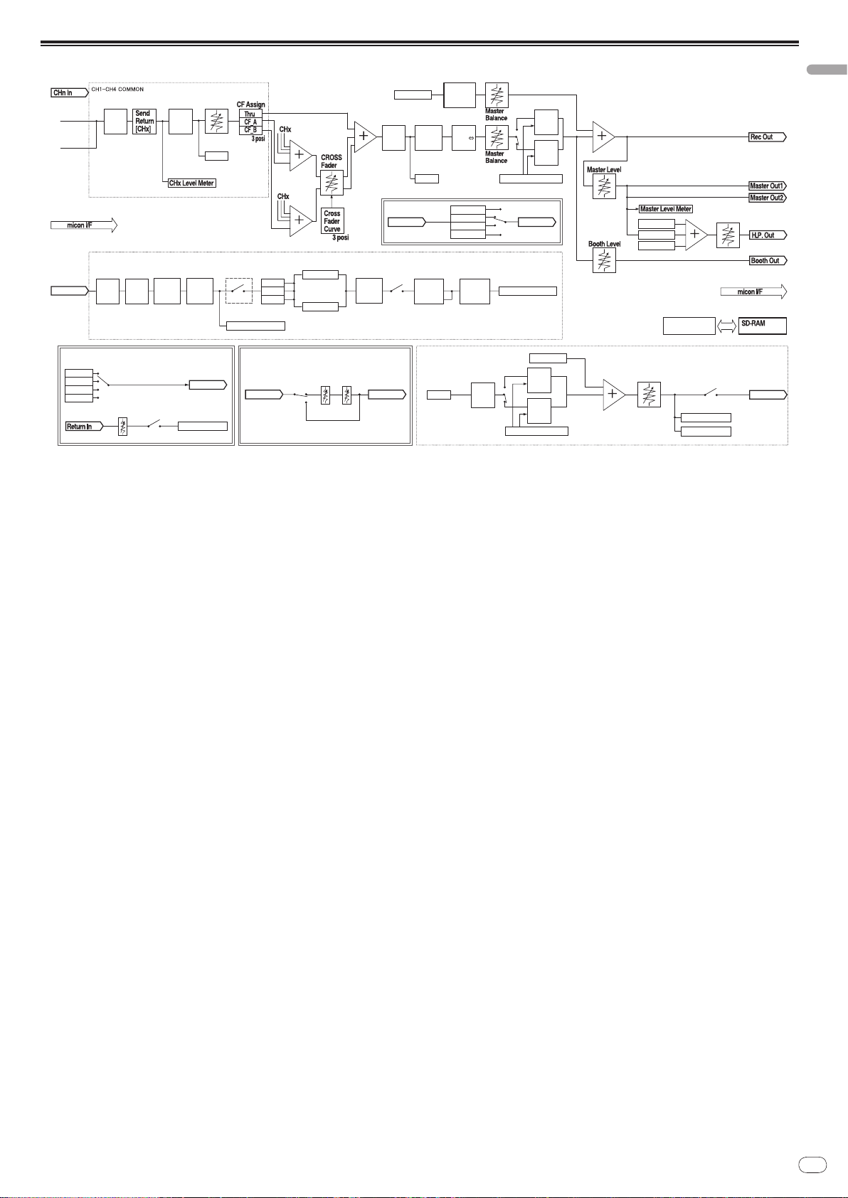
Block Diagram
Digital in
3Band
CHx
EQ
H.P
CUE
[CHx]
Analog in
Zone
CHx Fader
Send
Return
[Master]
Send
Return
[MIC1+2]
Sound
Maximizer
Normal
Talk
Over
Advanced
Talk
Over
Master
Mono
Stereo
Zone
Master MIC
Talk Over Parameter
Zone MIC
Normal
Talk
Over
Advanced
Talk
Over
Volume, Switch,Command
Master CUE
Zone CUE
CHx CUE
H.P. Level
Zone Level
Zone Out
Zone
CH
Select
Zone
Talk Over Parameter
Send Out
MIC 1/2 in
MIC 1/2 COMMON
3Band
MIC
EQ
MIC
Effect
MIC 1/2
Send
Return
MIC 1/2
Master
Both
Zone
Mic Level Indicator
Talk Over Parameter
EFFECT
Processing
Master Mic
Zone Mic
Mic SW
MIC 1/2
Low
Cut
Filter
Talk Over
Normal/
Advanced
Talk Over
Level
MIC
Detect
Filter
Talk Over
SW
Send/Return
SW
Return
Level
ON/OFF SW
CH 1-4
MIC 1/2
MIC 1+2
Master
Zone Level Meter
Zone CUE
Zone Out[ Sound Maximizer ]
[ Send/Return ]
CH Select
Send/Return Out
CH Level Meter
Master Level Meter
Zone Level Meter
MIC 1/2 Level Meter
ON/OFF
SW
Clarity Dynamics
OutIn
[ MIC Effect ]
MIC 1/2 OutMIC 1/2 In
Reverb
Echo+Verb
Octaver Pitch
Page 18

En
18
Specifications
General
Power requirements ........................AC 110 V to 120 V or 220 V to 240 V, 50 Hz/ 60 Hz
Power consumption .................................................................................................33 W
Main unit weight ..................................................................................................... 6.9 kg
External dimensions ............................482.6 mm (W) x 107.8 mm (H) x 225.1 mm (D)
Tolerable operating temperature .........................................................+5 °C to +35 °C
Tolerable operating humidity ...................................... 5 % to 85 % (no condensation)
Audio Section
Sampling rate ........................................................................................................96 kHz
A/ D, D/ A converter ................................................................................................. 24 bits
Frequency characteristic
CD/ LINE/ MIC .................................................................................... 20 Hz to 20 kHz
S/ N ratio (rated output)
CD/ LINE ...........................................................................................................102 dB
MIC .................................................................................................................... 84 dB
Total harmonic distortion (LINE — MASTER1)................................................. 0.005 %
Standard input level / Input impedance
MIC1, MIC2 ........................................................................................-52 dBu/ 22 kW
MIC3 ...................................................................................................-52 dBu/ 47 kW
CD/ LINE (3, 4).....................................................................................-12 dBu/ 47 kW
RETURN ..............................................................................................-12 dBu/ 47 kW
Standard output level / Load impedance / Output impedance
MASTER1 ...................................................................+8 dBu/
MASTER2 ...................................................................+2 dBu/
REC OUT .......................................................................-8 dBu/ 10 kW/ 10 W or lower
BOOTH ....................................................................................+8 dBu/ 10 kW/ 600 W
ZONE .................................................................... +8 dBu/ 10 kW/ 600 W (ATT 0 dB)
SEND ...........................................................................-12 dBu/ 10 kW/ 1 kW or lower
PHONES .....................................................................+8.5 dBu/ 32 W/ 22 W or lower
Rated output level / Load impedance
MASTER1 .........................................................................................+25 dBu/ 10 kW
MASTER2 .........................................................................................+20 dBu/ 10 kW
ZONE ............................................................................. +25 dBu/ 10 kW (ATT 0 dB)
Crosstalk (LINE) ...................................................................................................... 80 dB
Channel equalizer characteristic
HI .......................................................................................-26 dB to +6 dB (13 kHz)
MID .....................................................................................-26 dB to +6 dB (1 kHz)
LOW .................................................................................... -26 dB to +6 dB (70 Hz)
Microphone equalizer characteristic
HI .....................................................................................-12 dB to +12 dB (10 kHz)
MID ................................................................................-12 dB to +12 dB (2.5 kHz)
LOW ................................................................................ -12 dB to +12 dB (100 Hz)
Input / Output terminals
CD input terminal
RCA pin jack ............................................................................................................ 4
LINE input terminal
RCA pin jack ............................................................................................................ 2
MIC input terminal
XLR connector/ Phone jack (Ø 6.3 mm) ................................................................ 1
XLR connector ......................................................................................................... 1
Phone jack (Ø 6.3 mm) ...........................................................................................1
RETURN Input terminals
Phone jack (Ø 6.3 mm) ...........................................................................................1
ZONE output terminal
XLR connector ......................................................................................................... 1
MASTER output terminal
XLR connector ......................................................................................................... 1
RCA pin jack ............................................................................................................ 1
BOOTH output terminal
Phone jack (Ø 6.3 mm) ...........................................................................................1
REC OUT output terminal
RCA pin jack ............................................................................................................ 1
SEND output terminal
Phone jack (Ø 6.3 mm) ...........................................................................................1
DIGITAL IN coaxial input terminal
RCA pin jack ............................................................................................................ 2
PHONES output terminal
Stereo phone jack (Ø 6.3 mm) ............................................................................... 1
USB terminal
B-type ....................................................................................................................... 1
CONTROL terminal
Mini phone jack (Ø 3.5 mm) ................................................................................... 2
10 kW/ 10 W or lower
10 kW/ 10 W or lower
! The specifications and design of this product are subject to change without
notice.
! Published by Pioneer Corporation. Copyright © 2009 Pioneer Corporation. All
rights reserved.
Page 19

Page 20

Es
2
Le damos las gracias por la adquisición de este producto Pioneer. Lea a fondo estas instrucciones de utilización para que aprenda a utilizar correctamente su modelo.
El punto exclamativo dentro un triángulo
equilátero convenido para avisar el usuário
de la presencia de importantes
instrucciones sobre el funcionamiento y la
manutención en la libreta que acompaña el
aparato.
La luz intermitente con el símbolo de punta
de flecha dentro un triángulo equilátero.
Está convenido para avisar el usuario de la
presencia de “voltaje peligrosa” no aislada
dentro el producto que podría constituir un
peligro de choque eléctrico para las
personas.
ATENCIÓN:
PARA PREVENIR EL PELIGRO DE CHOQUE
ELÉCTRICO NO REMOVER LA TAPA NI LAS
PARTES DENTRO NO UTILIZADAS,
LLAMAR UNA PERSONA CUALIFICADA.
CAUTION
RISK OF ELECTRIC SHOCK
DO NOT OPEN
IMPORTANTE
D3-4-2-1-1_A1_Es
ADVERTENCIA
Este aparato no es impermeable. Para evitar el
riesgo de incendio y de descargas eléctricas, no
ponga ningún recipiente lleno de líquido (como
pueda ser un vaso o un florero) cerca del aparato ni
lo exponga a goteo, salpicaduras, lluvia o
humedad.
D3-4-2-1-3_A_Sp
ADVERTENCIA
La tensión de la red eléctrica es distinta según el
país o región. Asegúrese de que la tensión de la
alimentación de la localidad donde se proponga
utilizar este aparato corresponda a la tensión
necesaria (es decir, 230 V ó 120 V) indicada en el
panel posterior.
D3-4-2-1-4_A_Sp
Antes de enchufar el aparato a la corriente, lea la
sección siguiente con mucha atención.
ADVERTENCIA
Para evitar el peligro de incendio, no ponga nada
con fuego encendido (como pueda ser una vela)
encima del aparato.
D3-4-2-1-7a_A_Sp
PRECAUCIÓN PARA LA VENTILACIÓN
Cuando instale este aparato, asegúrese de dejar
espacio en torno al mismo para la ventilación con el
fin de mejorar la disipación de calor (por lo menos 5
cm en la parte trasera y 3 cm de cada lado).
ADVERTENCIA
Las ranuras y aberturas de la caja del aparato sirven
para su ventilación para poder asegurar un
funcionamiento fiable del aparato y para protegerlo
contra sobrecalentamiento. Para evitar el peligro de
incendio, las aberturas nunca deberán taparse ni
cubrirse con nada (como por ejemplo, periódicos,
manteles, cortinas) ni ponerse en funcionamiento el
aparato sobre una alfombra gruesas o una cama.
D3-4-2-1-7b_A_Sp
Entorno de funcionamiento
Temperatura y humedad del entorno de funcionamiento
+5 °C a +35 °C; menos del 85 % de humedad relativa
(rejillas de refrigeración no obstruidas)
No instale este aparato en un lugar mal ventilado, ni en
lugares expuestos a alta humedad o a la luz directa del
sol (o de otra luz artificial potente).
D3-4-2-1-7c*_A1_Es
Si la clavija del cable de alimentación de CA de este
aparato no se adapta a la toma de corriente de CA
que usted desea utilizar, deberá cambiar la clavija por
otra que se adapte apropiadamente. El reemplazo y
montaje de una clavija del cable de alimentación de
CA sólo deberá realizarlos personal de servicio
técnico cualificado. Si se enchufa la clavija cortada a
una toma de corriente de CA, puede causar fuertes
descargas eléctricas. Asegúrese de que se tira de la
forma apropiada después de haberla extraído.
El aparato deberá desconectarse desenchufando la
clavija de la alimentación de la toma de corriente
cuando no se proponga utilizarlo durante mucho
tiempo (por ejemplo, antes de irse de vacaciones).
D3-4-2-2-1a_A1_Es
PRECAUCIÓN
El interruptor de la alimentación POWER de este
aparato no corta por completo toda la alimentación
de la toma de corriente de CA. Puesto que el cable
de alimentación hace las funciones de dispositivo de
desconexión de la corriente para el aparato, para
desconectar toda la alimentación del aparato deberá
desenchufar el cable de la toma de corriente de CA.
Por lo tanto, asegúrese de instalar el aparato de
modo que el cable de alimentación pueda
desenchufarse con facilidad de la toma de corriente
de CA en caso de un accidente. Para evitar correr el
peligro de incendio, el cable de alimentación
también deberá desenchufarse de la toma de
corriente de CA cuando no se tenga la intención de
utilizarlo durante mucho tiempo seguido (por
ejemplo, antes de irse de vacaciones).
D3-4-2-2-2a_A_Sp
PRECAUCIONES CONCERNIENTES A LA
MANIPULACIÓN DEL CABLE DE
ALIMENTACIÓN
Tome el cable de alimentación por la clavija. No
extraiga la clavija tirando del cable. Nunca toque el
cable de alimentación cuando sus manos estén
mojadas, ya que esto podría causar cortocircuitos o
descargas eléctricas. No coloque la unidad, algún
mueble, etc., sobre el cable de alimentación. Asegúrese
de no hacer nudos en el cable ni de unirlo a otros
cables. Los cables de alimentación deberán ser
dispuestos de tal forma que la probabilidad de que
sean pisados sea mínima. Una cable de alimentación
dañado podrá causar incendios o descargas eléctricas.
Revise el cable de alimentación está dañado, solicite el
reemplazo del mismo al centro de servicio autorizado
PIONEER más cercano, o a su distribuidor.
S002*_Sp
Cuando emplee este producto, siga las
instrucciones escritas en la parte inferior de la
unidad, relacionadas con la tensión nominal, etc.
D3-4-2-2-4_Sp
Después de haber terminado de leer estas instrucciones, guárdelas en un lugar seguro para, en caso de ser necesario, consultarlas en el futuro.
En algunos países o regiones, la forma de la clavija de alimentación y del enchufe de corriente pueden ser diferentes de la mostrada en las ilustraciones de explicación.
Sin embargo, el método de conexión y operación del aparato es el mismo.
Page 21

Es
3
Español
Para uso exclusivo en Taiwán
Clavija Taiwanesa de dos
contactos planos
K056_A1_Es
SELECTOR DE TENSION DE LINEA
110-120V 220-240V
VOLTAGE
SELECTOR
El selector de tension esta situado en el panel posterior de esta consola de mezcla. El selector de tension sale de fabrica ajustado para 220-240 V. Compruebe
que este correctamente ajustado antes de enchufar el cable de alimentacion a
la toma de alimentacion. Si la tension no esta correctamente ajustada, ajuste el
selector del modo siguiente:
! Utilice un destornillador de tamano medio (cabeza plana). Inserte la punta del
destornillador en la ranura del selector y girelo de modo que la flecha indique la
tension de su zona.
! Para Taiwan, ajustelo para 110-120 V antes de ponerlo en funcionamiento.
Page 22

Es
4
Contenido
Cómo leer este manual
Los nombres de las visualizaciones, menús y botones de este manual van entre
corchetes. (Ej.: panel [Collection], menú [File], [f])
Antes de empezar a usar la unidad
Características ................................................................................................................5
Contenido de la caja .......................................................................................................5
Conexiones
Panel trasero ...................................................................................................................6
Conexión de terminales de entrada ..............................................................................7
Conexión de terminales de salida .................................................................................7
Conexión al panel de control .........................................................................................8
Conexión a un ordenador ...............................................................................................8
Acerca del software de controlador de audio USB ......................................................8
Acerca del ajuste del canal USB-MIDI ........................................................................10
Operaciones
Panel de control ............................................................................................................12
Operación de la sección DJ .........................................................................................13
Operación de la sección MC ........................................................................................14
Operación de la sección PA .........................................................................................15
Información adicional
Solución de problemas .................................................................................................16
Acerca de las cláusulas de exención ..........................................................................16
Diagrama en bloques ...................................................................................................17
Especificaciones ...........................................................................................................18
Montaje en una estantería según las
normas EIA
Los agujeros roscados situados a la derecha y a la izquierda del panel de control de
esta unidad concuerdan con el tamaño 5U de cualquier estantería de 483 mm de la
norma EIA. La profundidad máxima de esta unidad es de 225,1 mm.
! Asegure esta unidad con tornillos (no suministrados) aptos para la estantería.
! No instale directamente esta unidad encima de un amplificador de potencia.
La radiación de calor de un amplificador de potencia puede dañar esta unidad.
Además se puede producir ruido (de zumbido, etc.).
! Cuando transporte esta unidad, retírela de la estantería. Esta unidad puede
dañarse si se transporta sin quitarla de la estantería.
! Si transporta esta unidad sin quitarla de la estantería, asegúrese de que no la
sacude ni la golpea.
Page 23

Es
5
Sección PA
Antes de empezar a
usar la unidad
Características
El DJM-5000 es un mezclador de alta calidad y alto rendimiento diseñado para
reproducir un sonido de excelente calidad, y además está equipado con muchas
funciones que proporcionan un potente apoyo a tres funciones: MC, DJ y PA.
Procesamiento de sonido de alta calidad con muestreo de 96 kHz, convertidor A/
D de alta calidad de 24 bits y DSP de 32 bits para lograr un sonido potente de alta
calidad.
Una disposición del panel respetuosa con el usuario asigna las tres funciones
(MC, DJ y PA) en secciones separadas para poder realiza intuitivamente muchas
funciones.
Sección MC
Las características del micrófono proporcionan un
rendimiento MC de alta calidad (la página 14)
! Esta unidad está equipada con 2 canales exclusivos para un micrófono que se
puede usar intuitivamente. Según controla independientemente el volumen
y el ecualizador de 3 bandas, usted puede ajustar el volumen y la calidad del
sonido según la voz de un MC en cada canal.
! Esta unidad también está equipada con 4 tipos exclusivos de efectos para un
micrófono (REVERB/ ECHO+VERB/ OCTAVER/ PITCH). Con un micrófono se
puede realizar una gran variedad de actuaciones.
! CH1 en la sección DJ también está disponible para una entrada de micró-
fono. Puede usar hasta 3 micrófonos simultáneamente.
“Salida dividida MASTER/ ZONE” que permite actuaciones
individuales en dos lugares separados con un solo
aparato (la página 15)
! Esta unidad está equipada con salida de 2 canales asignada independiente-
mente a las salidas MASTER y ZONE. Puede reproducir sonido en canales
separados para 2 lugares, para celebrar con sonido flexible según la atmósfera de cada lugar. También puede reproducir el sonido de un micrófono en
un destino elegido, anunciando o actuando con un MC según la atmósfera de
cada lugar.
“SOUND MAXIMIZER” que puede reproducir el sonido
optimizado para condiciones o atmósferas específicas (la
página 15)
! Esta unidad está equipada con los mandos “DYNAMICS” y “CLARITY” para
ajustar la calidad del sonido. Puede crear un sonido de graves profundos en
la gama de frecuencias bajas y un sonido claro y nítido en la gama de frecuencias altas, lo que nunca antes ha sido posible con un ecualizador. Como
puede ajustar fácilmente la calidad del sonido en la gama de frecuencias
bajas y altas, también puede lograr un ajuste de sonido óptimo según avanza
una fiesta. Además, para un formato de sonido comprimido como MP3, el
sonido que se pierde en la gama de frecuencias bajas y altas se refuerza.
Contenido de la caja
! Cable de alimentación
! Cable USB
! CD-ROM
! Manual de Instrucciones (este manual)
Español
La primera función 1 “Advanced Talkover” del mundo (la
página 14)
! Esta unidad está equipada con la función “Advanced Talkover” que permite
escuchar mejor el sonido del micrófono al bajar automáticamente el volumen
en la gama de frecuencias de la voz comparado con la música. Usando un
micrófono no se afecta al volumen de la música, así que usted puede continuar con una actuación MC sin alterar la atmósfera del lugar (el nivel de la
música se puede ajustar con el mando del panel de control).
1 A partir de 8/ 10/ 2009, para un mezclador DJ, según lo ha determinado
Pioneer.
Sección DJ
Una “interfaz de audio USB” incorporada que permite
introducir directamente audio desde un ordenador (la
página 8)
! Esta unidad tiene una “interfaz de audio USB” incorporada que puede intro-
ducir el audio reproducido por un ordenador en un mezclador a través de la
conexión USB del ordenador. Esto hace posible que usted pueda realizar una
actuación DJ con una ordenador sin usar una tarjeta de sonido externa.
! Puede mezclar hasta 3 canales 2 de audio asignados a cada CH del DJM-
5000 con un solo ordenador.
2 Se suministra un CD-ROM con software controlador (compatible con
Windows y Mac). También puede usar la interfaz de audio instalando el software controlador en su ordenador (para Windows, usted puede asignar audio
de 3 canales sólo cuando se usa un software compatible con ASIO).
La función “MIDI USB asignable” que puede controlar un
software DJ compatible con MIDI (la página 10)
! Esta unidad está equipada con la función “MIDI USB asignable” que puede
transmitir información de funcionamiento de casi todos los botones y faders
del DJM-5000 a un software DJ en señales MIDI a través de la conexión USB
a un ordenador. También puede usar esto como un controlador MIDI con
operatividad flexible.
Page 24

Es
6
Conexiones
MASTER1
MASTER2
CH-4
ZONE
1 GND
1 GND
3 COLD
3 COLD
2 HOT
2 HOT
MASTER ATT.
-
12dB
-
6dB
0dB
-
12dB
-
6dB
0dB
ZONE ATT.
CD
L
L
L
L
RR
R
R
R
LINE
CH-3 CH-2 CH-1
DJM-
5000
CD CD
L
R
L
LINE
REC OUT
L
R
BOOTH
(TRS)
CONTROL
CD
R
L
CONTROL
SEND
L
(
MONO
)
R
L
(
MONO
)
R
L
R
RETURN
DIGITAL IN USB
21
MIC 3
MIC 2
1
6 72
3 3 4 4
4 4 5 5
16 141517 13 12 11 10
9 8
Asegúrese de desconectar la alimentación y desenchufar el cable de alimentación de la toma de corriente siempre que haga o cambie conexiones.
Consulte el manual de instrucciones del componente que va a ser conectado.
Conecte el cable de alimentación después de terminar las conexiones entre los aparatos.
Panel trasero
1 ZONE (la página 7)
Un terminal de salida para el canal ZONE.
2 ZONE ATT
Se usa para conmutar el nivel de atenuación de la salida de señales de audio
en el terminal [ZONE]. Seleccione entre 0 dB, -6 dB y -12 dB.
3 LINE (la página 7)
Conecte a una platina de casete o a un componente de salida de nivel de
línea.
4 CD (la página 7)
Conecte a un reproductor DJ o a un componente de salida de nivel de línea.
5 CONTROL (la página 7)
Éste es un terminal de control para un reproductor DJ. Use el fader de esta
unidad para controlar un reproductor DJ.
6 MIC3 (la página 7)
Conecte a un micrófono.
7 MIC2 (la página 7)
Conecte a un micrófono.
8 USB (la página 8)
Conecte a un ordenador.
9 DIGITAL IN (la página 7)
Conecte a un componente de salida de audio digital.
a RETURN (la página 7)
Conecte al terminal de salida de un efector externo. Cuando sólo está conectado el canal [L], la entrada del canal [L] entra simultáneamente al canal [R].
b SEND (la página 7)
Conecte al terminal de entrada de un efector externo. Cuando sólo está
conectado el canal [L] sale una señal de audio monofónico.
c BOOTH (la página 7)
Terminales de salida para un monitor de cabina, compatible con la salida
equilibrada o desequilibrada para un conector TRS.
d REC OUT (la página 7)
Éste es un terminal de salida para grabación.
e MASTER2 (la página 7)
Conecte a un amplificador de potencia, etc.
f MASTER ATT
Se usa para conmutar el nivel de atenuación de la salida de señales de audio
en el terminal [MASTER1] o [MASTER2]. Seleccione entre 0 dB, -6 dB y -12 dB.
g MASTER1 (la página 7)
Conecte a un amplificador de potencia, etc.
h AC IN
Conecte el cable de alimentación de CA suministrado a la entrada AC IN y,
a continuación, a una toma de corriente. Enchufe el cable de alimentación
después de haber hecho todas las conexiones.
Page 25

Es
7
Español
Conexión de terminales de entrada
MASTER1
MASTER2
CH-4
ZONE
1 GND
1 GND
3 COLD
3 COLD
2 HOT
2 HOT
MASTER ATT.
-
12dB
-
6dB
0dB
-
12dB
-
6dB
0dB
ZONE ATT.
CD
L
L
L
L
RR
R
R
R
LINE
CH-3 CH-2 CH-1
CD CD
L
R
L
LINE
REC OUT
L
R
CONTROL
CD
R
L
CONTROL
SEND
L
(
MONO
)
R
L
(
MONO
)
R
L
R
RETURN
DIGITAL IN USB
21
MIC 3
MIC 2
DJM-
5000
BOOTH
(TRS)
L
L
RR
L
L
RR
Reproductor DJ de Pioneer
1
Micrófono
A una toma de CA
Platina de casete, reproductor de CD, etc.
(un aparato de salida de nivel de línea)
Aparato de salida de audio digital
MASTER1
MASTER2
CH-4
ZONE
1 GND
1 GND
3 COLD
3 COLD
2 HOT
2 HOT
MASTER ATT.
-
12dB
-
6dB
0dB
-
12dB
-
6dB
0dB
ZONE ATT.
CD
L
L
L
L
RR
R
R
R
LINE
CH-3 CH-2 CH-1
CD CD
L
R
L
LINE
REC OUT
L
R
CONTROL
CD
R
L
CONTROL
SEND
L
(
MONO
)
R
L
(
MONO
)
R
L
R
RETURN
DIGITAL IN USB
21
MIC 3
MIC 2
DJM-
5000
BOOTH
(TRS)
R LR L
Amplificador
de potencia
2
Efector externo
Platina de casete, etc.
(un aparato de grabación
de entrada analógica)
Amplificador
de potencia
Amplificador
de potencia
Amplificador de
potencia (para un
monitor de cabina)
Habitación
principal
Habitación
secundaria
A una toma
de CA
1 Conecte un cable de control para usar la función de inicio de fader (la página 13).
Conexión de terminales de salida
2 Sale separadamente sonido de uno de los canales maestros (MASTER/ ZONE dividido).
Page 26

Es
8
PHONES
LEVEL
-
0
HEAD PHONES
NORMAL
ADVANCED
ON/OFF
TALK OVER
MIC1 ON
LEVEL
-
0
EFFECT
LOWHI
LOW
-
12 +12
MID
-
12 +12
HI
-
12 +12
OUTPUT
MASTER ZONE
BOTH
MIC 1 MIC 1
MIC2 ON
LEVEL
-
0
EFFECT
LOWHI
LOW
-
12 +12
MID
-
12 +12
HI
-
12 +12
OUTPUT
MASTER ZONE
BOTH
MIC 2
MINMAX
PITCHOCTAVER
ECHO+VERB
REVERB
MIC EFFECT
Auriculares
Micrófono
CH-1
CD
R
L
CONTROL
D
L
(
MONO
)
L
(
MONO
)
R
RETURN
DIGITAL IN USB
21
MIC 3
MIC 2
DJM-
5000
Ordenador
Conexión al panel de control
Conexión a un ordenador
Conecte con el cable USB suministrado.
Acerca del software de controlador de
audio USB
El software controlador es un controlador de audio que se usa exclusivamente
para enviar señales de audio desde un ordenador. Si quiere conectar esta unidad
a un ordenador que tiene instalado Windows o Mac, le recomendamos instalar
primero el software controlador en su ordenador.
! En nuestro sitio web (mostrado más abajo) puede encontrar la información
más reciente del software controlador.
http://www.prodjnet.com/support/
Contrato de Uso del Software
Este acuerdo de uso del software (de aquí en adelante “el acuerdo”) determina
los asuntos relacionados con el uso del software DJ (de aquí en adelante “el
software”) entre el cliente y Pioneer Corporation (de aquí en adelante “Pioneer”).
Asegúrese de leer atentamente los artículos siguientes antes de instalar y usar el
software. El uso del software da a entender que el cliente da su consentimiento al
acuerdo. Si no da su consentimiento al acuerdo, no instale ni use el software.
[Acuerdo de uso]
Bajo la condición de cumplir con el contenido de este acuerdo, el cliente tiene
permiso para instalar y usar este software en un solo ordenador personal.
[Restricciones]
El cliente no creará, distribuirá o enviará reproducciones de este software por
redes o de un ordenador a otro. Además, el cliente no modificará, venderá,
prestará, transferirá ni revenderá el software, ni distribuirá, creará, etc., trabajos secundarios del software. Asimismo, el cliente no aplicará la compilación
inversa, la ingeniería inversa ni el ensamblaje inverso, ni cambiará el software a
formatos perceptibles por el ser humano.
[Derechos de autor, etc.]
Los derechos de autor y otros derechos de la propiedad intelectual relacionados
con este software son propiedad de Pioneer y sus empresas afiliadas. Este software está protegido por las leyes de los derechos de autor y las disposiciones de
tratados internacionales.
[Rechazo de la garantía y la asistencia técnica]
Este software y todos los documentos asociados, etc., se provee “tal cual”.
Pioneer no garantiza al cliente ni a terceros la comerciabilidad, la compatibilidad
con fines específicos, la violación de los derechos de otros ni ningún otro asunto,
ni garantiza el apoyo técnico relacionado con este software o la documentación
asociada. Note que el rechazo de la garantía puede no ser reconocido en algunos
países y regiones según disposiciones obligatorias, en cuyo caso, este rechazo
de la garantía no se aplicará. Los derechos del cliente pueden ser diferentes en
algunos países o regiones.
[Limitación de responsabilidad]
Pioneer y otros proveedores de este software no aceptarán ninguna responsabilidad, sea cual fuere, por los daños sufridos al usar o no poder usar este software o
ninguna documentación asociada (incluyendo, pero sin limitarse a, la pérdida de
beneficios, interrupciones de negocios, daños resultantes de la pérdida de información o problemas con ella, etc.), aunque Pioneer haya sido avisada de tales
daños. La limitación de responsabilidad relacionada con los daños fortuitos o
directos puede no ser reconocida en algunos países y regiones según disposiciones obligatorias, en cuyo caso, esta limitación de responsabilidad no se aplicará.
Note que, independientemente del caso, la responsabilidad de Pioneer y sus subsidiarias con respecto a este software no excederá la suma pagada por el cliente
a Pioneer o a sus subsidiarias. Este rechazo de la limitación de responsabilidad
es un elemento fundamental del acuerdo entre el cliente y Pioneer.
[Ley aplicable]
Este acuerdo cumple con las leyes y ordenanzas de Japón y será interpretado
en consecuencia. Este acuerdo estipula todos los artículos del mismo entre el
cliente y Pioneer, y se aplicará con prioridad sobre cualquier acuerdo previo y
existente relacionado con este asunto (independientemente de si éste es oral o
escrito). El Juzgado del Distrito de Tokio será el que tenga jurisdicción exclusiva
en primera instancia para dirimir cualquier disputa que surja relacionada con
este acuerdo.
Page 27

Es
9
Español
Cuidados para la instalación
! Antes de instalar el software controlador asegúrese de apagar esta unidad y
desconectar el cable USB de esta unidad y de su ordenador.
! Si conecta esta unidad a su ordenador sin instalar primero el software con-
trolador puede que se produzca un error en su ordenador dependiendo del
ambiente del sistema.
! Si ha interrumpido el proceso de instalación mientras éste se ejecutaba,
empiece de nuevo desde el principio siguiendo el procedimiento siguiente.
! Lea cuidadosamente las disposiciones del Contrato de Uso del Software
antes de instalar el software controlador para uso exclusivo con esta unidad.
! Antes de instalar el software controlador, termine de ejecutar todos los
demás programas en su ordenador.
! El software controlador es compatible con los sistemas operativos siguientes.
— Mac OS X (10.3.9 y posterior)
— Windows Vista® Home Basic/ HomePremium/ Ultimate/ Business
— Windows
El software controlador no es compatible con un sistema operativo de 64 bits
OS (Windows® XP Professional x64 edition y Windows Vista® 64 bits).
! El CD-ROM con software controlador incluye un instalador que funciona en
los 12 idiomas siguientes.
Inglés, francés, alemán, italiano, holandés, español, portugués, ruso, chino
simplificado, chino tradicional, coreano y japonés
Si el idioma de su sistema operativo no es uno de los listados más arriba,
seleccione [English (Inglés)] siguiendo las instrucciones de la pantalla.
®
XP Home Edition/ Professional (SP2 o posterior)
Instalación del software controlador
Procedimiento de instalación (Windows)
Lea cuidadosamente “Cuidados para la instalación” antes de instalar el software
controlador.
! Para instalar o desinstalar el software controlador necesitará la autorización
del administrador de su ordenador. Inicie la sesión como administrador de su
ordenador antes de proseguir con la instalación.
1 Inserte el CD-ROM suministrado en la unidad de CD de su
ordenador
La carpeta del CD-ROM aparece.
! Si la carpeta del CD-ROM no se visualiza después de cargar un CD-ROM,
abra la unidad de CD desde [Equipo (o Mi PC)] en el menú [INICIO].
2 Haga doble clic en [DJM-5000_X.XXX.exe]
La pantalla de instalación del controlador aparece.
3 Cuando aparezca la pantalla de selección de idioma,
seleccione [Español] y haga clic en [OK]
Puede seleccionar uno de múltiples idiomas dependiendo del ambiente del
sistema de su ordenador.
4 Lea cuidadosamente el Contrato de Uso del Software y, si
acepta las disposiciones, ponga una marca de verificación en
[Acepto.] y haga clic en [OK]
Si no acepta las disposiciones del Contrato de Uso del Software haga clic en
[Cancel] detenga la instalación.
5 Siga con la instalación según las instrucciones de la pantalla
Si aparece [Seguridad de Windows] en la pantalla mientras se realiza la insta-
lación, haga clic en [Instalar este software de controlador de todas formas] y
continúe con la instalación.
! Cuando lo instale en Windows XP
Si aparece [Instalación de hardware] en la pantalla mientras se realiza la
instalación, haga clic en [Continuar] y continúe con la instalación.
! Cuando termina la instalación del programa aparece un mensaje de
terminación.
! Cuando termine la instalación del software controlador, necesitará reiniciar
su ordenador.
Procedimiento de instalación (Macintosh)
Lea cuidadosamente “Cuidados para la instalación” antes de instalar el software
controlador.
! Para instalar o desinstalar el software controlador necesitará la autorización
del administrador de su ordenador. Prepare de antemano el nombre y la
contraseña del administrador de su ordenador.
1 Inserte el CD-ROM suministrado en la unidad de CD de su
ordenador
La carpeta del CD-ROM aparece.
! Haga doble clic en el icono CD del escritorio cuando la carpetas no se visuali-
cen después de haber cargado el CD-ROM.
2 Haga doble clic en [DJM-5000_M_X.X.X.dmg]
La pantalla de menú [DJM-5000AudioDriver] aparece.
3 Haga doble clic en [DJM-5000AudioDriver.pkg]
La pantalla de instalación del controlador aparece.
4 Verifique los detalles en la pantalla y haga clic en [Continuar]
5 Cuando aparezca la pantalla del Contrato de Uso del
Software, seleccione [Español], lea cuidadosamente el Contrato
de Uso del Software y haga clic en [Continuar]
Puede seleccionar uno de múltiples idiomas dependiendo del ambiente del
sistema de su ordenador.
6 Si está de acuerdo con las disposiciones del Contrato de
Licencia del Usuario del Software, haga clic en [Acepto]
Si no acepta las disposiciones del Contrato de Uso del Software haga clic en [En
desacuerdo] detenga la instalación.
7 Siga con la instalación según las instrucciones de la pantalla
! Para detener la instalación, haga clic en [Cancelar].
! Cuando termine la instalación del software controlador, necesitará reiniciar
su ordenador.
Conexión del DJM-5000 y un ordenador
1 Conecte esta unidad a su ordenador con un cable USB
Esta unidad funcione como un aparato de audio conforme a las normas ASIO.
! Cuando usa aplicaciones que soportan ASIO se pueden usar como entradas
[USB 1/ 2], [USB 3/ 4] y [USB 5/ 6].
! Cuando usa aplicaciones que soportan DirectX sólo se puede usar como
entrada [USB 5/ 6].
! El ambiente de funcionamiento recomendado para el ordenador depende de
la aplicación de DJ. Asegúrese de verificar el ambiente de funcionamiento
recomendado para la aplicación de DJ que usted esté usando.
2 Pulse [POWER]
Conecte la alimentación de esta unidad.
! El mensaje [Instalando software de controlador de dispositivo] puede apa-
recer cuando se conecta el DJM-5000 al ordenador por primera vez o cuando
se reconecta al puerto USB del ordenador. Espere a que aparezca el mensaje
[Los dispositivos están listos para usarse].
! Cuando lo instale en Windows XP
— [¿Desea que Windows se conecte a Windows Update para buscar el
software?] puede aparecer durante la instalación. Seleccione [No por el
momento] y haga clic en [Siguiente] para continuar la instalación.
— [¿Qué desea que haga el asistente?] puede aparecer durante la insta-
lación. Seleccione [Instalar automáticamente el software (recomen-
dado)] y haga clic en [Siguiente] para continuar la instalación.
— Si aparece [Seguridad de Windows ] en la pantalla mientras se realiza
la instalación, haga clic en [Instalar este software de controlador de
todas formas] y continúe con la instalación.
Page 28

Es
10
Ajuste del tamaño de la memoria intermedia
dB
14
9
5
2
0
–2
–4
–7
–10
–15
LR
(Windows)
Use este procedimiento para ajustar la capacidad de la memoria intermedia del
ordenador cuando se usa el controlador de audio ASIO.
Haga clic en el menú [INICIO] de Windows >[Todos los
programas]>[Pioneer]>[DJM-5000]>[Utilidad de configuración
ASIO del DJM-5000 ]
Una memoria intermedia lo suficientemente grande reduce la posibilidad de que
se pierda sonido (interrupción de sonido) pero aumenta el retardo de transmisión
de la señal de audio (latencia).
! Cuando se ejecuta un programa de aplicación (software DJ, etc.) con esta
unidad establecida como aparato fijo, termine el programa antes de ajustar el
tamaño de la memoria intermedia.
Verificación de la versión del software
controlador
Procedimiento para verificar (Windows)
Acerca del ajuste del canal USB-MIDI
Desconecte de antemano la alimentación de esta unidad.
1 Ponga [MIDI] en [ON]
2 Mantenga pulsado simultáneamente [FADER START] para
[CH-1] y [CH-2] y luego pulse [POWER]
Cuando los botones MASTER [CUE] y ZONE [CUE] se encienden en color
naranja se establece el modo de ajuste del canal MIDI. Mantenga pulsado
[FADER START] para [CH-1] y [CH-2] hasta que los botones se encienda en color
naranja.
! El ajuste actual de canal MIDI se visualiza en el indicador de nivel maestro.
[L] muestra la posición de 10 y [R] la posición de 1.
! El canal MIDI se ajusta inicialmente en [1].
Ejemplo: para mostrar 16
Haga clic en el menú [INICIO] de Windows >[Todos los
programas]>[Pioneer]>[DJM-5000]>[Utilidad de visualización de
la versión del DJM-5000]
La pantalla [Version] aparece.
Procedimiento para verificar (Macintosh)
Haga clic en [Apple]>[Acerca de este Mac]>[Más
información]>[Extensiones]>[DJM-5000 USBAudio].
La pantalla [Versión] aparece.
Verificación de la información más reciente en
el software controlador
Visite nuestro sitio web indicado abajo para conocer la información más reciente
del software controlador que se va a usar exclusivamente con esta unidad.
http://www.prodjnet.com/support/
3 Pulse [CUE] en el canal [MASTER]
El canal MIDI cambia un canal cada vez que lo pulsa.
Seleccione un canal MIDI para cambiar el ajuste.
4 Pulse y mantenga pulsado [CUE] para el canal [ZONE].
Guarde los cambios hechos para el canal MIDI.
Mientras se guardan los ajustes, [ON/ OFF] parpadea para el canal
[SOUND MAXIMIZER]. Se enciende al terminar de guardarse los datos.
! No desconecte la alimentación durante el ajuste de canales MIDI.
5 Pulse [POWER]
Desconecte la alimentación de esta unidad.
6 Pulse [POWER]
Conecte de nuevo la alimentación de esta unidad.
Inicie el modo normal. El ajuste de canal MIDI cambia.
Page 29

Es
11
Español
Lista de mensajes MIDI
Categoría
CH-1
CH-2
CH-3
CH-4
CROSS
FADER
MASTER
ZONE
SOUND
MAXIMIZER
Nombre de
interruptor
HI
MID
LOW
FADER START
CUE
Fader de canal VR Bn 11 dd 0-127
Conmutador de
asignación de
crossfader
HI
MID
LOW
FADER START
CUE
Fader de canal VR Bn 12 dd 0-127
Conmutador de
asignación de
crossfader
HI
MID
LOW
CUE
Fader de canal VR Bn 13 dd 0-127
Conmutador de
asignación de
crossfader
HI
MID
LOW
CUE
Fader de canal VR Bn 14 dd 0-127
Conmutador de
asignación de
crossfader
Crossfader VR Bn 0B dd 0-127
CROSS FADER
LEVEL
CUE
BALANCE
MONO/
REO
BOOTH MONITOR
LEVEL
CUE
ZONE ASSIGN
CH-1
ZONE ASSIGN
CH-2
ZONE ASSIGN
CH-3
ZONE ASSIGN
CH-4
ZONE ASSIGN
MASTER
ZONE ASSIGN
OFF
OFF BTN Bn 63 dd OFF=0, ON=127
ON/
CLARITY
DYNAMICS
OFF BTN Bn 4E dd OFF=0, ON=127
ON/
Tipo de
interruptor
VR Bn 2 dd 0-127
VR Bn 3 dd 0-127
VR Bn 4 dd 0-127
BTN Bn 58 dd OFF=0, ON=127
BTN Bn 46 dd OFF=0, ON=127
Interruptor
VR Bn 7 dd 0-127
VR Bn 8 dd 0-127
VR Bn 9 dd 0-127
BTN Bn 59 dd OFF=0, ON=127
BTN Bn 47 dd OFF=0, ON=127
Interruptor
VR Bn OE dd 0-127
VR Bn OF dd 0-127
VR Bn 15 dd 0-127
BTN Bn 48 dd OFF=0, ON=127
Interruptor
VR Bn 51 dd 0-127
VR Bn 5C dd 0-127
VR Bn 52 dd 0-127
BTN Bn 49 dd OFF=0, ON=127
Interruptor
Interruptor
VR Bn 18 dd 0-127
BTN Bn 4A dd OFF=0, ON=127
VR Bn 17 dd 0-127
STE-
Interruptor
VR Bn 19 dd 0-127
VR Bn 61 dd 0-127
BTN Bn 62 dd OFF=0, ON=127
Interruptor
Interruptor
Interruptor
Interruptor
Interruptor
Interruptor
VR Bn 64 dd 0-127
VR Bn 65 dd 0-127
Mensajes
MIDI
Notas
MSB
Bn 41 dd A=0, THRU=64, B=127
Bn 42 dd A=0, THRU=64, B=127
Bn 43 dd A=0, THRU=64, B=127
Bn 44 dd A=0, THRU=64, B=127
Bn 5F dd
Bn 60 dd MONO=0, STEREO=127
Bn 20 dd 127
Bn 21 dd 127
Bn 22 dd 127
Bn 23 dd 127
Bn 24 dd 127
Bn 25 dd 127
Izquierda=0, Medio=64,
Derecha=127
Categoría
SEND/
RETURN
TALK OVER
MIC EFFECT
HEAD
PHONES
MIC 1
MIC 2
! MIDI ON/
! “n” en el mensaje MIDI “Bn” es un valor del canal MIDI establecido por el usuario, con
Nombre de
interruptor
SEND/
RETURN
CH-1
RETURN
SEND/
CH-2
RETURN
SEND/
CH-3
RETURN
SEND/
CH-4
RETURN
SEND/
MIC 1
RETURN
SEND/
MIC 2
RETURN
SEND/
MIC 1+2
RETURN
SEND/
MASTER
LEVEL
OFF VR Bn 40 dd OFF=0, ON=127
ON/
LEVEL
NORMAL/
ADVANCED
OFF BTN Bn 69 dd OFF=0, ON=127
ON/
REVERB
ECHO+VERB
OCTAVER
PITCH
LEVEL
HI
MID
LOW
EFFECT
MIC1 ON
HI
MID
LOW
EFFECT
MIC2 ON
OFF controla si se transmiten mensajes MIDI.
un margen de 0x00 a 0x0F (1 a 16 en la pantalla de ajuste)
Tipo de
interruptor
Interruptor
Interruptor
Interruptor
Interruptor
Interruptor
Interruptor
Interruptor
Interruptor
VR Bn 66 dd 0-127
VR Bn 67 dd 0-127
Interruptor
BTN Bn 6A dd OFF=0, ON=127
BTN Bn 6B dd OFF=0, ON=127
BTN Bn 6C dd OFF=0, ON=127
BTN Bn 6D dd OFF=0, ON=127
VR Bn 1A dd 0-127
VR Bn 1E dd 0-127
VR Bn 6E dd 0-127
VR Bn 1F dd 0-127
VR Bn 70 dd 0-127
BTN Bn 71 dd OFF=0, ON=127
VR Bn 72 dd 0-127
VR Bn 73 dd 0-127
VR Bn 74 dd 0-127
VR Bn 75 dd 0-127
BTN Bn 76 dd OFF=0, ON=127
Mensajes
MIDI
Notas
MSB
Bn 30 dd 127
Bn 31 dd 127
Bn 32 dd 127
Bn 33 dd 127
Bn 34 dd 127
Bn 35 dd 127
Bn 36 dd 127
Bn 37 dd 127
Bn 68 dd
NORMAL=0,
ADVANCED=127
Page 30

Es
12
Operaciones
DJM-
5000
PROFESSIONAL MIXER
PHONES
LEVEL
-
0
HEAD PHONES
PITCHOCTAVER
ECHO+VERB
REVERB
MIC EFFECT
NORMAL
ADVANCED
ON/OFF
TALK OVER
MIN MAX
MIC1 ON
LEVEL
-
0
EFFECT
LOWHI
LOW
-
12 +12
MID
-
12 +12
HI
-
12 +12
OUTPUT
MASTER ZONE
BOTH
MIC 1 MIC 1
MIC2 ON
LEVEL
-
0
EFFECT
LOWHI
LOW
-
12 +12
MID
-
12 +12
HI
-
12 +12
OUTPUT
MASTER ZONE
BOTH
MIC 2
ABTHRU
CH -1
LOW
-
26
+6
MID
-
26
+6
HI
-
26
+6
CUE
FADER
START
TRIM
-
+9
CD
MIC 3
DIGITAL1
dB
14
9
5
2
0
–2
–4
–7
–10
–15
ABTHRU
CH -2
LOW
-
26
+6
MID
-
26
+6
HI
-
26
+6
CUE
FADER
START
TRIM
-
+9
CD
USB 1/2
DIGITAL2
dB
14
9
5
2
0
–2
–4
–7
–10
–15
ABTHRU
CH -3
LOW
-
26
+6
MID
-
26
+6
HI
-
26
+6
CUE
TRIM
-
+9
CD
USB 3/4
LINE
dB
14
9
5
2
0
–2
–4
–7
–10
–15
ABTHRU
CH -4
LOW
-
26
+6
MID
-
26
+6
HI
-
26
+6
CUE
TRIM
-
+9
CD
USB 5/6
LINE
dB
14
9
5
2
0
–2
–4
–7
–10
–15
OFFON
MIDI
CROSS
FADER
BOOTH MONITOR
-
0
STEREOMONO
BALANCE
L
R
CUE
dB
14
9
5
2
0
–2
–4
–7
–10
–15
LR
LEVEL
-
0
MASTER
ZONE ON
CUE
1
2
34
MASTER
MIC
dB
14
9
5
2
0
–2
–4
–7
–10
–15
LEVEL
-
0
ZONE
ZONE ASSIGN
POWER
SOUND
MAXIMIZER
DYNAMICS
MINMAX
CLARITY
MINMAX
ON/OFF
1
2
3
4
MIC1
MIC2
MIC1+2
MASTER
SEND/RETURN
LEVEL
MINMAX
ON/OFF
Sección MC Sección DJ Sección PA
7
b
5
1
3
2
8
9
a
4
7
6
665
1
3
2
8
4
7
65
5
1
2
8
7
8
4
1
2
4
2
3
4
6
8
7
1
9
a
5
b
c
d
1
2
4
3
5
6
9
7
8
a
b
i
c
d
e
f
g
h
MIC 1
MIC 2
TALK OVER
HEAD PHONES
CH-1
CH-4
CROSS FADER
MIDI
MASTER
ZONE
SOUND MAXIMIZER
SEND/ RETURN
POWER
Panel de control
Sección MC
,
1 MIC 1 (la página 14)
2 OUTPUT (la página 14)
3 HI, MID, LOW (la página 14)
4 EFFECT (la página 14)
5 MIC EFFECT (la página 14)
Indicador de nivel de pico (la página 14)
6
7 LEVEL (la página 14)
8 MIC1 ON, MIC2 ON (la página 14)
9 Nivel de Talk-Over (la página 14)
a NORMAL/
b ON/
c LEVEL (la página 13)
d PHONES (la página 13)
ADVANCED (la página 14)
OFF (la página 14)
8 Conmutador de asignación de
crossfader (la página 13)
9 Crossfader (la página 13)
a CROSS FADER (Conmutador selector
de curva de crossfader) (la página 13)
b MIDI (la página 13)
Sección PA
1 LEVEL (la página 13)
2 Indicador de nivel maestro (la página 13)
Visualiza el nivel de las señales de audio que
han pasado por [LEVEL] en el canal [MASTER].
3 CUE (la página 13)
4 BALANCE (la página 15)
5 MONO/
6 BOOTH MONITOR (la página 15)
STEREO (la página 15)
e ON/
OFF (la página 15)
f Conmutador selector de canal de
salida (la página 15)
g LEVEL (la página 15)
h ON/
OFF (la página 15)
i POWER (la página 13)
Sección DJ
1 Conmutador selector de entrada (la
página 13)
2 TRIM (la página 13)
3 FADER START (la página 13)
4 CUE (la página 13)
5 Indicador de nivel de canal (la página 13)
6 HI, MID, LOW (la página 13)
7 Fader de canal (la página 13)
—
7 LEVEL (la página 15)
8 Indicador de nivel de zona (la página 15)
9 CUE (la página 13)
a Conmutador selector de canal de
salida (la página 15)
b ZONE ON (la página 15)
Visualiza el nivel de las señales de audio que
han pasado por [LEVEL] en el canal [ZONE].
c CLARITY (la página 15)
d DYNAMICS (la página 15)
Page 31

Es
13
Español
Operación de la sección DJ
ON
OFF
OFF
ON
ON
OFF
ON
OFF
ON
OFF
ON
OFF
ON
ON
OFF
OFF
ON
OFF
ON
ON
ON
CH (L)
MASTER (L)
ZONE (L)
CH (MONO)
CH (MONO)
MASTER (L)+ZONE (L)
CH (MONO)
CH (R)
MASTER (R)
ZONE (R)
MASTER (MONO)
ZONE (MONO)
MASTER (R)+ZONE (R)
MASTER (MONO)
+ZONE (MONO)
CH-1
‒
CH-4
MASTER ZONE
Salida de auriculares
Canal izquierdo
Canal derecho
Salida de sonido
1 Pulse [POWER]
Conecte la alimentación de esta unidad.
2 Ajuste el conmutador selector de entrada
Seleccione la fuente de entrada de cada canal desde los componentes conectados a esta unidad.
! Para enviar sonido al ordenador conectado al terminal [USB], ponga el con-
mutador selector de entrada para [CH-2], [CH-3] y [CH-4] en [USB].
3 Gire [TRIM]
Ajusta el nivel de las señales de audio introducidas en cada canal.
! El indicador de nivel de canal se enciende cuando el sonido entra correcta-
mente en el canal.
4 Ponga el fader de canal en la posición interior
Ajusta el nivel de las señales de audio que salen en cada canal.
5 Ajusta el conmutador de asignación de crossfader
Cambia el destino de salida de cada canal.
— [A]: Asigna a [A] (izquierda) del crossfader.
— [B]: Asigna a [B] (derecha) del crossfader.
— [THRU]: Asigna al canal [MASTER] (el crossfader no es atravesado).
6 Ajusta el conmutador de curva de crossfader ([CROSS FADER])
Cambia las características de curva de crossfader.
— [ ]: Hace una curva que aumenta bruscamente (si el crossfader se
separa del lado [A] salen inmediatamente señales de audio desde el lado
[B]).
— [ ]: Hace una curva que está a medias de las dos curvas de arriba y
abajo.
— [ ]: Hace una curva que aumenta gradualmente (si el crossfader se
separa del lado [A], el sonido del lado [B] aumenta gradualmente, mientras que el sonido del lado [A] se reduce gradualmente).
7 Ajuste el crossfader
Envía señales de audio asignadas por el conmutador de asignación de crossfader
correspondiente a las características de curva seleccionadas por [CROSS FADER]
(conmutador selector de curva de crossfader).
! No necesita seguir este paso cuando el conmutador de asignación de
crossfader está en [THRU].
8 Gire [LEVEL] para el canal [MASTER]
El sonido sale por [MASTER1] y [MASTER2]. El indicador de nivel maestro se
enciende.
Uso del fader para reproducir en un reproductor
DJ de Pioneer (inicio de fader)
Si conecta un reproductor DJ de Pioneer usando un cable de control (suministrado con el reproductor DJ), usted puede iniciar la reproducción o el control de
otra operaciones del reproductor DJ con el fader de esta unidad.
La función de inicio del fader sólo está disponible cuando un reproductor DJ de
Pioneer está conectado a [CH-1] o [CH-2].
Conecte de antemano un reproductor DJ de Pioneer a esta unidad (la página 7).
Inicie la reproducción usando un fader de canales
1 Ajuste el conmutador de asignación de crossfader en [THRU]
2 Pulse [FADER START]
Active la función de inicio del fader. El botón se enciende intensamente en color
naranja.
3 Ponga el fader de canal en la posición más exterior
4 Ajuste el cue del reproductor DJ
El reproductor DJ hace una pausa en la reproducción en el punto cue.
5 Ponga el fader de canal en la posición interior
La reproducción empieza en el reproductor DJ.
! Si vuelve a ajustar el fader de canal en la posición original, el reproductor
vuelve instantáneamente al punto cue ya establecido y hace una pausa en la
reproducción (vuelta a punto cue).
Inicie la reproducción usando el crossfader
1 Ajuste el conmutador de asignación de crossfader en [A] o [B]
2 Pulse [FADER START]
Active la función de inicio del fader. El botón se enciende intensamente en color
naranja.
3 Ajuste el crossfader
Póngalo en el extremo más alejado en sentido opuesto al canal que se va a iniciar con el fader.
4 Ajuste el cue del reproductor DJ
El reproductor DJ hace una pausa en la reproducción en el punto cue.
5 Ajuste el crossfader
La reproducción empieza en el reproductor DJ.
! Si vuelve a ajustar el crossfader en la posición original, el reproductor vuelve
instantáneamente al punto cue ya establecido y hace una pausa en la reproducción (vuelta a punto cue).
Ajuste de la calidad del sonido
Gire [HI], [MID] o [LOW] en cada canal
Consulte Especificaciones en la página 18 para conocer el margen de sonido que
se puede ajustar con cada control.
Monitoreo de sonido con auriculares
1 Conecte los auriculares al conector [PHONES]
2 Pulse [CUE] para el canal que va a ser monitoreado
El botón se enciende intensamente en color naranja.
3 Gire el dial [LEVEL] para [HEAD PHONES]
El sonido sale de los auriculares por el canal seleccionado con [CUE].
! El sonido que sale de los auriculares cambia según la combinación de cana-
les seleccionados con [CUE]. Vea la tabla de abajo.
! El monitoreo se cancela si pulsa de nuevo [CUE]. El botón se enciende débil-
mente en color naranja.
Operación del software DJ
El DJM-5000 envía también los datos de operación para los botones y diales en el
formato MIDI. Si conecta un ordenador con un software DJ compatible con MIDI
incorporado a través de un cable USB, usted podrá utilizar el software DJ en esta
unidad.
Instale de antemano el software DJ en su ordenador. Además, haga los ajustes
de audio y MIDI para el software DJ.
1 Conecte el puerto USB de esta unidad a su ordenador
Para conocer detalles de las conexiones, vea Conexión a un ordenador en la
página 8.
2 Inicie el software DJ
3 Ponga [MIDI] en [ON]
La transmisión del mensaje MIDI empieza.
! Puede enviar mensajes MIDI según la posición de los botones, faders o man-
dos de control (instantánea).
! Ajuste los faders y mandos de control para transmitir mensajes basados en la
posición correspondiente. Para conocer detalles de los mensajes generados
por esta unidad, vea Lista de mensajes MIDI en la página 11.
4 Ponga [MIDI] en [OFF]
Los mensajes MIDI no se transmiten aunque usted utiliza esta unidad.
Page 32

Es
14
Operación de la sección MC
dB
Frecuencia
NORMAL
ADVANCED
dB
Frecuencia
NORMAL
ADVANCED
Uso de un micrófono
1 Cambie [OUTPUT]
Seleccione el destino del sonido que sale del canal [MIC1] o [MIC2].
2 Gire [LEVEL] para el canal del micrófono
Ajusta el nivel de las señales de audio que salen del canal del micrófono.
! Tenga en cuenta que girar hasta la posición del extremo derecho da salida a
un sonido muy alto.
3 Pulse [MIC1 ON] para el canal [MIC1] o [MIC2 ON] para el canal
[MIC2].
Encienda el canal del micrófono. El botón se enciende en color verde.
4 Introduzca señales de audio en el micrófono
El sonido sale al destino de salida seleccionado en el paso 1.
! El indicador de nivel de pico se enciende en diferentes colores correspondien-
tes al nivel de audio que está siendo introducido.
— Verde: Nivel permitido
— Naranja: Nivel apropiado
— Rojo: Nivel excesivo (baje el nivel de audio girando [LEVEL] a la
izquierda)
Ajuste de la calidad del sonido
Gire [HI], [MID] o [LOW] para el canal [MIC1] o [MIC2]
Consulte Especificaciones en la página 18 para conocer el margen de sonido que
se puede ajustar con cada control.
Uso de la función de efecto del micrófono
Uso de la función talk-over
1 Gire el control de nivel de talk-over
Establezca el nivel de atenuación del sonido y también el del canal del micrófono.
2 Cambie entre [NORMAL]/ [ADVANCED]
El modo de atenuación para la función talk-over cambia.
! Talk-over normal:
La salida de sonido para los canales que no sean el del micrófono se
atenúa según se ha establecido para el nivel talk-over.
! Talk-over avanzado:
Sólo la banda de voz de la salida de sonido de los canales que no sean el
del micrófono se atenúa según se ha establecido para el nivel talk-over.
3 Pulse [ON/ OFF] para [TALK OVER]
Active la función talk-over. El botón se enciende en color rojo.
! Cuando las señales de audio se introducen en el canal del micrófono, el
sonido, además del que corresponde al canal del micrófono, se atenúa según
el ajuste del modo de atenuación y la posición del control.
1 Pulse [MIC EFFECT (REVERB, ECHO+VERB, OCTAVER o PITCH)]
Active la función de efecto del micrófono. El botón parpadea en azul.
! El efecto varía dependiendo del botón.
2 Gire [EFFECT]
Añade un efecto a la salida de sonido del canal del micrófono.
! El efecto varía según el sentido de giro y la posición de [EFFECT].
Nombre de
efecto
1
REVERB
ECHO+VERB
1
OCTAVER
PITCH
1 Cuando más lo gira a la derecha, más alto es el sonido del efecto.
! Cuando desactive la función de efectos del micrófono, pulse una vez el botón
[MIC EFFECT (REVERB, ECHO+VERB, OCTAVER, PITCH)] parpadeante. El
botón se enciende en color azul.
Descripciones
Añade efecto de reverberación al sonido original.
1
Añade efectos de reverberación y eco al sonido original.
Añade sonido con 1 octava por arriba o por debajo del sonido original.
Cambia el intervalo musical dentro de un margen de 1 octava por
arriba o por abajo. Gírelo a derecha o izquierda para cambiar el intervalo de 1 octava por arriba o por abajo respectivamente.
Page 33

Es
15
Español
Operación de la sección PA
dB
Frecuencia
DYNAMICS
MINMAX
CLARITY
MINMAX
Salida de sonido del terminal ZONE
Puede enviar sonido desde el terminal [ZONE], además del sonido que sale del
canal maestro.
1 Ajuste el conmutador selector de canal de salida para el canal
[ZONE]
Seleccione la salida de canal del terminal [ZONE].
! La salida de sonido varía según la posición del conmutador.
Posición
del conmutador
Salida de
audio
1 Sale audio independientemente de la posición de los faders y mandos de control.
2 Sale audio independientemente de la posición de [LEVEL] para el canal [MASTER].
3 El audio sólo sale del canal del micrófono, para el que [OUTPUT] se pone en [BOTH] o
2 Pulse [ZONE ON] para el canal [ZONE]
Encienda el canal [ZONE]. El botón se enciende en color verde.
3 Gire [LEVEL] para el canal [ZONE]
El sonido sale por el terminal [ZONE]. El indicador de nivel de zona se enciende.
! Para apagar el canal [ZONE], pulse de nuevo [ZONE ON]. El botón se apaga.
Uso de la función del maximizador de sonido
1 Pulse [ON/ OFF] para [SOUND MAXIMIZER]
Active la función de máximizador de sonido. El botón se enciende en color azul.
2 Gire [CLARITY] o [DYNAMICS]
El efecto del maximizador de sonido varía según el sentido de giro y la posición
del control.
! El nivel de audio de salida aumenta según el efecto maximizador de sonido
1 2 3 4 MASTER MIC
[ZONE].
CH-1
1
CH-21CH-31CH-4
1
Canal del
micrófono
2
Canal de
micrófono
3
cuando el dial se gira a la derecha. Ponga atención al nivel de audio de salida
cuando use la función del maximizador de sonido.
4 Gire el dial [LEVEL] para [SEND/ RETURN]
Ajusta el nivel de las señales de audio introducidas por el terminal [RETURN].
! Para detener la salida de sonido por el terminal [SEND], pulse el botón [ON/
OFF] parpadeante. El botón se enciende.
Cambio entre audio mono y estéreo
Puede cambiar entre audio mono y estéreo para la salida de sonido en el terminal [MASTER1], [MASTER2], [BOOTH], [REC OUT] o [PHONES].
Cambie entre [MONO]/ [STEREO]
! [MONO]: Envía audio mono.
! [STEREO]: Envía audio estéreo.
Ajuste de balance L/ R de audio
El balance derecho/ izquierdo de la salida de sonido por los terminales
[MASTER1], [MASTER2], [BOOTH], [REC OUT] y [PHONES] se puede ajustar.
1 Ponga [MONO]/ [STEREO] en [STEREO]
2 Gire [BALANCE]
El balance L/ R de audio varía según el sentido de giro y la posición del control
[BALANCE].
! El giro a la posición del extremo derecho sólo envía sonido del canal derecho
de audio estéreo. El giro a la posición del extremo izquierdo sólo envía sonido
del canal izquierdo de audio estéreo.
Sale audio del terminal [BOOTH]
El audio del canal maestro, excepto el del canal del micrófono, sale por el
terminal [BOOTH] independientemente de la posición de [LEVEL] en el canal
[MASTER].
Gire [BOOTH MONITOR]
Ajusta el nivel de las señales de audio que salen por el terminal [BOOTH].
! El margen de sonido que se puede ajustar varía según el control.
— CLARITY: Ajusta el ataque y configura el sonido principalmente en la
gama media y alta (platillos dobles, caja, etc.).
— DYNAMICS: Ajusta la modulación y el ritmo, principalmente en la gama
baja.
! Cuando desactive la función del maximizador de sonido, pulse de nuevo [ON/
OFF]. La luz del botón se apaga.
Uso del efector externo
1 Conecte el efector externo
[ON/ OFF] de [SEND/ RETURN] se enciende en rojo. Cuando no está conectado el
efector externo no se enciende [ON/ OFF].
! Para conocer detalles de las conexiones, vea Conexiones en la página 6.
2 Ajuste el conmutador selector de canal de salida para el canal
[SEND/
RETURN]
Seleccione la salida de canal del terminal [SEND].
! La salida de sonido varía según la posición del conmutador.
Posición
del conmutador
Salida de
audio
1 El sonido del micrófono que sale del canal maestro se envía desde el canal [SEND].
3 Pulse [ON/ OFF] para [SEND/ RETURN]
El sonido sale por el terminal [SEND]. El botón parpadea en rojo.
1 2 3 4 MIC 1 MIC 2 MIC1+2 MASTER
CH-1 CH-2 CH-3 CH-4 MIC 1 MIC 2
MIC1+2
1
Canal maestro
Page 34

Es
16
Información adicional
Solución de problemas
! La operación incorrecta se confunde a menudo con un problema o un fallo de funcionamiento. Si piensa que algo funciona mal con este componente, compruebe
los puntos de abajo. Algunas veces, el problema puede estar en otro componente. Inspeccione los otros componentes y los aparatos eléctricos que esté utilizando.
Si no se puede corregir el problema después de comprobar los elementos de abajo, pida al servicio de Pioneer autorizado más cercano o a su concesionario que
realice el trabajo de reparación.
! El reproductor puede no funcionar bien debido a la electricidad estática o a otras influencias externas. En tales casos, el funcionamiento normal se puede restaurar
desenchufando el cable de alimentación y volviéndolo a enchufar.
Problema Verificación Remedio
La alimentación no se conecta. ¿Está bien conectado el cable de alimentación? Enchufe el cable de alimentación a una toma de CA.
No hay sonido o éste está muy bajo. ¿Está en la posición correcta el conmutador selector de
Sonido distorsionado. ¿Está bien ajustado el nivel de audio que sale del canal
No se puede usar crossfade. ¿Está bien ajustado el conmutador de asignación de
No se puede iniciar un reproductor DJ con fader. ¿Está apagado [FADER START]? Ponga [FADER START] en (la página 13).
No hay efecto. ¿Está [EFFECT] en la posición apropiada? Ponga [EFFECT] en una posición que no sea [LOW] (la página 12).
No se puede usar un efector externo. ¿Está encendido [SEND/
Sonido distorsionado de un efector externo. ¿Está bien ajustado el nivel de la entrada de audio proce-
Esta unidad no se reconoce después de ser conectada
a un ordenador.
entrada?
¿Están bien conectados los cables de conexión? Conecte correctamente los cables de conexión (la página 7).
¿Están sucios los terminales y las clavijas? Limpie los terminales y las clavijas antes de hacer conexiones.
¿Está [MASTER ATT] del panel trasero ajustado a un nivel
como de -12 dB?
del micrófono?
¿Está bien ajustado el nivel de audio introducido en cada
canal?
crossfader?
¿Está el reproductor DJ bien conectado al terminal [CON-
TROL]?
¿Están bien conectados los cables de audio? Conecte esta unidad al terminal de salida de audio de un reproductor DJ
RETURN] [ON/ OFF]? Pulse [ON/ OFF] de [SEND/ RETURN] para encender [SEND/ RETURN] (la
¿Está el efector externo bien conectado al terminal [SEND]
o [RETURN]?
¿Está bien ajustado el conmutador de canal de salida
RETURN]?
[SEND/
dente del efector?
¿Está bien instalado el software controlador en su orde-
nador?
Cambie la fuente de entrada de un canal con el conmutador selector de
entrada (la página 12).
Cambie [MASTER ATT] (la página 6).
Ajuste el dial [LEVEL] para [MASTER] de forma que el indicador de nivel de
canal maestro se encienda a unos 0 dB en el nivel de pico (la página 12).
Ajuste [MASTER ATT] en [-6 dB] o [-12 dB] (la página 6).
Ajuste el control [TRIM] de forma que el indicador de nivel del canal se
encienda cerca de 0 dB al nivel de pico (la página 12).
Ajuste bien el conmutador de asignación de crossfader para cada canal (la
página 12).
Conecte un reproductor DJ al terminal [CONTROL] con un cable de control
(la página 7).
con un cable de audio (la página 7).
página 12).
Conecte un efector externo al terminal [SEND] o [RETURN]. Cuando la
conexión está bien hecha, [ON/
(la página 7).
Cambie el canal de salida con el conmutador selector de canal de salida(la
página 12).
Gire el dial [LEVEL] para [SEND/
audio desde el efector externo (la página 12).
Instale el software controlador. Reinstálelo si el software controlador ya
está instalado (la página 8).
A menos que esta unidad se conecte correctamente al ordenador y no haya
error en la transmisión de datos, el programa de utilidad de visualización
de la versión no podrá visualizar el firmware de esta unidad. Para conocer
detalles de cómo verificar, vea Verificación de la versión del software controla-
dor en la página 10.
OFF] de [SEND/ RETURN] se enciende en rojo
RETURN] para ajustar la salida de nivel de
Acerca de las cláusulas de exención
! Pioneer es una marca registrada de Pioneer Corporation.
! Microsoft
fábrica de Microsoft Corporation en los Estados Unidos y/ o en otros países.
! Pentium es una marca registrada de Intel Corporation.
! Adobe y Reader son marcas registradas o marcas de fábrica de Adobe Systems
Incorporated en los Estados Unidos y/
! Apple, Macintosh o Mac OS son marcas registradas de Apple Inc. en los
Estados Unidos y/ o en otros países.
! ASIO es una marca de fábrica de Steinberg Media Technologies GmbH.
! Los nombres de compañías y productos mencionados aquí son marcas de
fábrica de sus respectivos propietarios.
®
, Windows Vista® y Windows® son marcas registradas o marcas de
o en otros países.
Este producto cuenta con licencia para se usado sin fines de lucro. Este producto
no tiene licencia para ser usado con fines comerciales (con fines de lucro) como,
por ejemplo, en emisiones (terrestres, por satélite, por cable u otros tipos de emisiones), streaming en Internet, Intranet (un red corporativa) u otros tipos de redes,
ni para distribuir información electrónica (servicio de distribución de música digital en línea). Para tales usos necesita adquirir las licencias correspondientes. Para
conocer detalles, visite http:/ / www.mp3licensing.com.
La tecnología de compresión de audio para MP3 se ofrece bajo licencia de
Fraunhofer IIS y Thomson Multimedia.
Page 35

Es
17
Español
Diagrama en bloques
Digital in
3Band
CHx
EQ
H.P
CUE
[CHx]
Analog in
Zone
CHx Fader
Send
Return
[Master]
Send
Return
[MIC1+2]
Sound
Maximizer
Normal
Talk
Over
Advanced
Talk
Over
Master
Mono
Stereo
Zone
Master MIC
Talk Over Parameter
Zone MIC
Normal
Talk
Over
Advanced
Talk
Over
Volume, Switch,Command
Master CUE
Zone CUE
CHx CUE
H.P. Level
Zone Level
Zone Out
Zone
CH
Select
Zone
Talk Over Parameter
Send Out
MIC 1/2 in
MIC 1/2 COMMON
3Band
MIC
EQ
MIC
Effect
MIC 1/2
Send
Return
MIC 1/2
Master
Both
Zone
Mic Level Indicator
Talk Over Parameter
EFFECT
Processing
Master Mic
Zone Mic
Mic SW
MIC 1/2
Low
Cut
Filter
Talk Over
Normal/
Advanced
Talk Over
Level
MIC
Detect
Filter
Talk Over
SW
Send/Return
SW
Return
Level
ON/OFF SW
CH 1-4
MIC 1/2
MIC 1+2
Master
Zone Level Meter
Zone CUE
Zone Out[ Sound Maximizer ]
[ Send/Return ]
CH Select
Send/Return Out
CH Level Meter
Master Level Meter
Zone Level Meter
MIC 1/2 Level Meter
ON/OFF
SW
Clarity Dynamics
OutIn
[ MIC Effect ]
MIC 1/2 OutMIC 1/2 In
Reverb
Echo+Verb
Octaver Pitch
Page 36

Es
18
Especificaciones
Generales
Requisitos de potencia.......................CA 110 V a 120 V, o 220 V a 240 V, 50 Hz/ 60 Hz
Consumo de energía ................................................................................................33 W
Peso de la unidad principal .................................................................................. 6,9 kg
Dimensiones externas..................... 482,6 mm (An) x 107,8 mm (Al) x 225,1 mm (Pr)
Temperatura de funcionamiento tolerable .......................................... +5 °C a +35 °C
Humedad de funcionamiento tolerable ..................... 5 % a 85 % (sin condensación)
Sección de audio
Frecuencia de muestreo .......................................................................................96 kHz
Convertidor A/ D y D/ A ...........................................................................................24 bits
Características de frecuencia
CD/ LINE/ MIC ..................................................................................... 20 Hz a 20 kHz
Relación señal/ ruido (salida nominal)
CD/ LINE ...........................................................................................................102 dB
MIC .................................................................................................................... 84 dB
Distorsión armónica total (LINE — MASTER1) ................................................0,005 %
Nivel de entrada / Impedancia de entrada estándar
MIC1, MIC2 ........................................................................................-52 dBu/ 22 kW
MIC3 ...................................................................................................-52 dBu/ 47 kW
CD/ LINE (3, 4).....................................................................................-12 dBu/ 47 kW
RETURN ..............................................................................................-12 dBu/ 47 kW
Nivel de salida / Impedancia de carga / Impedancia de salida estándar
MASTER1 ..................................................................+8 dBu/
MASTER2 ..................................................................+2 dBu/
REC OUT ......................................................................-8 dBu/ 10 kW/ 10 W o menos
BOOTH ....................................................................................+8 dBu/ 10 kW/ 600 W
ZONE .................................................................... +8 dBu/ 10 kW/ 600 W (ATT 0 dB)
SEND ..........................................................................-12 dBu/ 10 kW/ 1 kW o menos
PHONES ....................................................................+8,5 dBu/ 32 W/ 22 W o menos
Nivel de salida nominal / Impedancia de carga
MASTER1 .........................................................................................+25 dBu/ 10 kW
MASTER2 .........................................................................................+20 dBu/ 10 kW
ZONE ............................................................................. +25 dBu/ 10 kW (ATT 0 dB)
Diafonía (LINE) ........................................................................................................ 80 dB
Características del ecualizador de canales
HI ........................................................................................ -26 dB a +6 dB (13 kHz)
MID ......................................................................................-26 dB a +6 dB (1 kHz)
LOW ..................................................................................... -26 dB a +6 dB (70 Hz)
Características del ecualizador del micrófono
HI ...................................................................................... -12 dB a +12 dB (10 kHz)
MID .................................................................................-12 dB a +12 dB (2,5 kHz)
LOW ................................................................................. -12 dB a +12 dB (100 Hz)
Terminales entrada / salida
Terminal de entrada CD
Conector de contactos RCA ..................................................................................4
Terminal de entrada LINE
Conector de contactos RCA ..................................................................................2
Terminal de entrada MIC
Conector XLR/ Conector fonográfico (Ø 6,3 mm) ................................................ 1
Conector XLR ........................................................................................................... 1
Conector fonográfico (Ø 6,3 mm) .......................................................................... 1
Terminales de entrada RETURN
Conector fonográfico (Ø 6,3 mm) .......................................................................... 1
Terminal de salida ZONE
Conector XLR ........................................................................................................... 1
Terminal de salida MASTER
Conector XLR ........................................................................................................... 1
Conector de contactos RCA ..................................................................................1
Terminal de salida BOOTH
Conector fonográfico (Ø 6,3 mm) .......................................................................... 1
Terminal de salida REC OUT
Conector de contactos RCA ..................................................................................1
Terminal de salida SEND
Conector fonográfico (Ø 6,3 mm) .......................................................................... 1
Terminal de entrada coaxial DIGITAL IN
Conector de contactos RCA ..................................................................................2
Terminal de salida PHONES
Conector fonográfico estéreo (Ø 6,3 mm) ............................................................ 1
Terminal USB
Tipo B .......................................................................................................................1
Terminal CONTROL
Miniconector fonográfico (Ø 3,5 mm)................................................................... 2
10 kW/ 10 W o menos
10 kW/ 10 W o menos
! Las especificaciones y diseño de este producto están sujetos a cambios sin
previo aviso.
! Publicado por Pioneer Corporation. Copyright © 2009 Pioneer Corporation.
Todos los derechos reservados.
Page 37

Page 38

Zhtw
2
感謝您購買先鋒產品。 請詳閱操作手冊以瞭解正確操作購買機型的方式。 閱畢手冊後,請妥善收藏以便未來參考。
ݨཏٲ
ԋ၇ҐᐡȂ፝ጃۢӶҐᐡѳڻႲ٘ޠޫпւ
ȞġĶġŤŮȃІڎġĴġŤŮпαȟȄ
ឍ֚
ᐡ෧αڏԥϟᖂራІπңܼȂпጃߴҐࠣϟҔள
ᐈձٯ٪ЦႇዦȄ࣐ᗘռЭدȂ፝Ͻஈ༭πܗңޑࠣ
ȞԄൣિȃҁȃᛩᄎȟڐ᙮ᇑȂη፝ϽӶࠕ෨ܗטα
ᐈձҐᐡȄ
D3-4-2-1-7b_B_ChH
ңܼѯᢋӵୣ
ѯᢋᚗရࡶ҂ඩᓟ
K056_A1_Zhtw
110-120V 220-240V
VOLTAGE
SELECTOR
在有些國家或地區中,電源插頭和電源開關的形狀有時和說明圖片顯示的不同。但是連接和操作方法相同。
線路電壓選擇開關
線路電壓選擇開關位於本混音器的側面板上。電壓選擇開關的原廠設定為
220 V 至 240 V。將電源線插入電源插座之前,檢查是否已正確設定此開
關。如果未正確設定電壓,或您移到電壓規定不同的地區,請依下列指示
調整選擇開關:
! 使用中等尺寸(一字型)螺絲起子。將螺絲起子的尖端插入選擇開關的
溝槽中,然後設定選擇開關,使您所在地區的電壓標記對齊箭頭。
! 對於台灣機型,請在使用前設定為 110 V 至 120 V。
Page 39

Zhtw
3
中文
目錄
如何閱讀本手冊
本手冊中的顯示器、選單及按鈕名稱皆加上括號。 (例如 [Collection] 窗
格、[File] 選單、[f])
使用前
功能與特色 ................................................... 4
包裝內容物 ................................................... 4
連接
後面板 ....................................................... 5
連接輸入端子 ................................................. 6
連接輸出端子 ................................................. 6
連接至控制面板 ............................................... 7
連接至電腦 ................................................... 7
關於 USB 音訊驅動程式軟體 ..................................... 7
關於 USB-MIDI 頻道設定 ........................................ 9
操作
控制面板 .................................................... 11
操作 DJ 部分 ................................................. 12
操作 MC 部分 ................................................. 13
操作 PA 部分 ................................................. 14
其他資訊
故障排除 .................................................... 15
關於免責條款 ................................................ 15
區塊圖 ...................................................... 16
規格 ........................................................ 17
安裝符合 EIA 標準的機架
本裝置左右控制面板上的螺絲孔與任何具 EIA 標準的 19 吋機架 5U 尺
寸相符。 本裝置最大深度為 225.1 mm。
! 請以符合機架的螺絲(未隨附)固定本裝置。
! 請勿直接在功率放大器上安裝本裝置。 功率放大器的散熱可能會破壞
本裝置。 此外,可能會產生噪音(嗡嗡聲等)。
! 搬運本裝置時,請由機架取出。 搬運本裝置時不取下機架可能會導致
本裝置受損。
! 若您不取下機架即搬運本裝置,請確定本裝置不會因此震動或碰撞。
Page 40

Zhtw
4
PA 部分
使用前
功能與特色
DJM-5000 是一套高品質、高效能的混音器,專門為高音質而設計且配
備眾多功能,可提供下列三角色強大的支援能力:MC、DJ 及 PA。
採用 96 kHz 取樣、24 位元高品質 A/ D 轉換器和 32 位元 DSP 高音質處
理,可表現出強大、高階的聲音。
使用方便的面板配置將三角色(MC、DJ 及 PA)分佈在獨立的區域,以
便直接操作眾多功能。
MC 部分
麥克風功能可忠實呈現高品質的 MC 效能(第 13頁)
! 本裝置配備有 2 個麥克風專門頻道,可進行人性化的操作。 由於
您可獨立控制音量及 3 組調節等化器,因此可依照 MC 在各頻道的
聲音調整音量及音質。
! 本裝置也配備有 4 種麥克風專用音效(REVERB/
OCTAVER/ PITCH)。 使用麥克風執行多樣化的表演不再遙不可及。
! DJ 部分中的 CH1 也適用於麥克風輸入。 您最多可同時使用 3 組麥克風。
1
全球首創
! 本裝置配備有「Advanced Talkover」功能,可透過自動降低相對
音樂的語音頻率範圍音量,讓麥克風的音效更適合聆聽。 使用麥
克風不會影響音樂的音量,能讓您繼續 MC 表演而不會破壞場地的
氣氛(使用控制面板上的旋鈕可調整音樂音量)。
1 自 8/
,「Advanced Talkover」功能(第 13頁)
10/ 2009起,由先鋒認可之 DJ 混音器。
ECHO+VERB/
利用「MASTER/
處不同的場所進行獨立表演(第 14頁)
! 本裝置配備有指定至 MASTER 輸出及 ZONE 輸出之2 頻道獨立輸出。
您可在不同的頻道中輸出音效至 2 處場所,並依各場地的氣氛而
定,成就靈活的派對表演。 同樣的,您也可由麥克風輸出音效至
所選目的地,依據各場所的氣氛來完成公開發表或 MC 表演。
「SOUND MAXIMIZER」可為指定的環境或氣氛實現最適當音效設定
(第 14頁)
! 本裝置配備有可調整音質的「DYNAMICS」及「CLARITY」旋鈕。 您可
在低頻範圍中產生沈重的低音音效,在中高範圍中產生清晰的音效,
而在等化器中無法達到這種效果。 由於可輕鬆調整高低頻率範圍中
的音質,因此您可依照派對的發展實現完美的音效設定。 此外對於像
MP3 的壓縮音效格式而言,在高低頻率範圍中遺失的音效將加以補強。
ZONE 分割輸出」功能後,僅需一部裝置就能在 2
包裝內容物
! 電源線
! USB 連接線
! CD-ROM
! 操作手冊(本手冊)
DJ 部分
內建「USB 音訊介面」,可由電腦直接輸入音訊(第 7頁)
! 本裝置擁有內建「USB 音訊介面」,可將電腦上播放的音訊輸入至
使用 USB 連接電腦的混音器。 此功能可讓您實現使用無外接音效
卡電腦的 DJ 表演。
! 2只利用一部電腦,就能混合指定各 DJM-5000 的 CH 多達 3 頻道音訊。
2 隨附內含驅動程式軟體的 CD-ROM(相容 Windows及 Mac)。 您
可在電腦上安裝驅動程式軟體,以使用音訊介面功能(如使用
Windows,只有在使用 ASIO 相容軟體時才能指定 3 頻道音訊)。
「可指定式 USB MIDI」功能可操控 MIDI 相容的 DJ 軟體(第 9頁)
! 本裝置配備有「可指定式 USB MIDI」功能,可透過與電腦的 USB
連線,以 MIDI 訊號傳送幾乎所有 DJM-5000 按鈕及音量滑鈕的操作
資訊到 DJ 軟體。 您也可當成 MIDI 控制器使用,以供彈性操作。
Page 41

Zhtw
5
連接
MASTER1
MASTER2
CH-4
ZONE
1 GND
1 GND
3 COLD
3 COLD
2 HOT
2 HOT
MASTER ATT.
-
12dB
-
6dB
0dB
-
12dB
-
6dB
0dB
ZONE ATT.
CD
L
L
L
L
RR
R
R
R
LINE
CH-3 CH-2 CH-1
DJM-
5000
CD CD
L
R
L
LINE
REC OUT
L
R
BOOTH
(TRS)
CONTROL
CD
R
L
CONTROL
SEND
L
(
MONO
)
R
L
(
MONO
)
R
L
R
RETURN
DIGITAL IN USB
21
MIC 3
MIC 2
1
6 72
3 3 4 4
4 4 5 5
16 141517 13 12 11 10
9 8
確定在每次接線或變更接線之前,關閉電源並從電源插座上拔下電源線。
有關已連接元件,請參閱操作手冊。
完成裝置之間的所有接線後,請連接電源線。
後面板
中文
1 ZONE ( 第 6頁)
ZONE頻道輸出端子。
2 ZONE ATT
用於切換 [ZONE] 端子的音訊訊號輸出衰減量。 選項有 0 dB、-6
dB 及 -12 dB。
3 LINE ( 第 6頁)
連接至錄音帶卡座或電平輸出元件。
4 CD ( 第 6頁)
連接至 DJ 播放機或電平輸出元件。
5 CONTROL ( 第 6頁)
此為 DJ 播放機的控制端子。 使用本裝置的音量滑鈕控制 DJ 播放機。
6 MIC3 ( 第 6頁)
連接至麥克風。
7 MIC2 ( 第 6頁)
連接至麥克風。
8 USB ( 第 7頁)
連接至電腦。
9 DIGITAL IN ( 第 6頁)
連接至數位音訊輸出元件。
f MASTER ATT
用於切換 [MASTER1]或[MASTER2] 端子的音訊訊號輸出衰減
量。 選項有 0 dB、-6 dB 及 -12 dB。
g MASTER1 ( 第 6頁)
連接至功率放大器等。
h AC IN
連接隨機附贈的 AC 電源連接線至 AC IN 插座,然後將插頭插入電
源輸出插座。完成所有連線後,再插入電源線。
a RETURN ( 第 6頁)
連接至外接效果器的輸出端子。 只連接 [L] 頻道時,[L] 頻道輸
入會同時輸入至 [R] 頻道。
b SEND ( 第 6頁)
連接至外接效果器的輸入端子。 只連接 [L] 頻道時,會輸出單聲
道音訊訊號。
c BOOTH ( 第 6頁)
Booth 監視器的輸出端子與 TRS 接頭的對稱或不對稱輸出相容。
d REC OUT ( 第 6頁)
此為錄製的輸出端子。
e MASTER2 ( 第 6頁)
連接至功率放大器等。
Page 42

Zhtw
6
連接輸入端子
MASTER1
MASTER2
CH-4
ZONE
1 GND
1 GND
3 COLD
3 COLD
2 HOT
2 HOT
MASTER ATT.
-
12dB
-
6dB
0dB
-
12dB
-
6dB
0dB
ZONE ATT.
CD
L
L
L
L
RR
R
R
R
LINE
CH-3 CH-2 CH-1
CD CD
L
R
L
LINE
REC OUT
L
R
CONTROL
CD
R
L
CONTROL
SEND
L
(
MONO
)
R
L
(
MONO
)
R
L
R
RETURN
DIGITAL IN USB
21
MIC 3
MIC 2
DJM-
5000
BOOTH
(TRS)
L
L
RR
L
L
RR
ബջ
łń Ⴌྜඩ৵
ᓄழћ৵ȃńŅ ክܺᐡ๊
Ȟྜᒰя၇ဋȟ
՞ଊᒰя၇ဋ
ӒᎣ Ņŋ ክܺᐡ
1
MASTER1
MASTER2
CH-4
ZONE
1 GND
1 GND
3 COLD
3 COLD
2 HOT
2 HOT
MASTER ATT.
-
12dB
-
6dB
0dB
-
12dB
-
6dB
0dB
ZONE ATT.
CD
L
L
L
L
RR
R
R
R
LINE
CH-3 CH-2 CH-1
CD CD
L
R
L
LINE
REC OUT
L
R
CONTROL
CD
R
L
CONTROL
SEND
L
(
MONO
)
R
L
(
MONO
)
R
L
R
RETURN
DIGITAL IN USB
21
MIC 3
MIC 2
DJM-
5000
BOOTH
(TRS)
łń Ⴌྜඩ৵
R LR L
ѓ౦ܺτᏣ
2
ѓ౦ܺτᏣ
ȞᎍңܼġŃŰŰŵũᆀຝᏣȟ
ѵ௦Ꮳ
ᓄழћ৵๊
ȞЩᒰΤᓄᇨ၇ဋȟ
ѓ౦ܺτᏣѓ౦ܺτᏣ
лܙ
φܙ
1 連接控制連接線以使用音量滑鈕啟動功能(第 12頁 )。
連接輸出端子
2 音效會從其中一個主要頻道中個別輸出(MASTER/ ZONE分割輸出)。
Page 43

Zhtw
7
中文
連接至控制面板
PHONES
LEVEL
-
0
HEAD PHONES
NORMAL
ADVANCED
ON/OFF
TALK OVER
MIC1 ON
LEVEL
-
0
EFFECT
LOWHI
LOW
-
12 +12
MID
-
12 +12
HI
-
12 +12
OUTPUT
MASTER ZONE
BOTH
MIC 1 MIC 1
MIC2 ON
LEVEL
-
0
EFFECT
LOWHI
LOW
-
12 +12
MID
-
12 +12
HI
-
12 +12
OUTPUT
MASTER ZONE
BOTH
MIC 2
MINMAX
PITCHOCTAVER
ECHO+VERB
REVERB
MIC EFFECT
ബջ
Շᐡ
CH-1
CD
R
L
CONTROL
D
L
(
MONO
)
L
(
MONO
)
R
RETURN
DIGITAL IN USB
21
MIC 3
MIC 2
DJM-
5000
Ⴌဟ
關於 USB 音訊驅動程式軟體
此驅動程式軟體屬於專門用來輸出電腦音訊訊號的音訊驅動程式。 若
您想要連接本裝置與安裝 Windows或 Mac 的電腦,建議您先在電腦中
安裝驅動程式軟體。
! 您可在本公司網站找到最新的驅動程式軟體資訊(顯示如下)。
http://www.prodjnet.com/support/
軟體使用協議
本軟體使用協議(此後稱為「協議」)可判定客戶與 Pioneer
Corporation(此後稱為「先鋒」)間,相關 DJ 功能軟體(此後稱為
「軟體」)使用之問題。
安裝與使用軟體前,請務必詳閱下列文章。 使用本軟體即暗示客戶已
同意本協議。 若您不同意協議內容,請勿安裝或使用本軟體。
[ 使用協議 ]
在遵守本協議內容的情況下,客戶有權在單一個人電腦上安裝與使用本軟體。
[限制]
客戶不得透過網路建立、散佈或傳送本軟體之拷貝,或在電腦間傳輸。 另
外,客戶不得修改、販售、租賃、傳輸或轉售本軟體,亦不得散佈、建立
軟體之次要工作等。 此外,客戶不得反向編譯、反向工程、反向組裝或其
他以人力將本軟體變更為可察覺之格式。
[ 版權等 ]
本軟體相關之版權及所有其他智慧財產權皆為先鋒及其子公司之財產。
本軟體受版權法保護,以及國際條約規範。
連接至電腦
使用隨附的 USB 連接線連接。
[ 拒絕保障及技術支援 ]
本軟體及所有相關說明文件等乃根據「現狀」提供。 先鋒不擔保客戶及第
三方關於適售性、相容特定用途、違反其他或任何其他問題,以及與本軟
體相關之技術支援或有關說明文件。 請注意,在部分國家及地區中依據強
制性條款可能不承認拒絕保障,在此情況下將不適用本拒絕保障。 在部分
國家及地區中,客戶權利可能有所不同。
[ 責任限制 ]
先鋒及本軟體之其他供應商對因使用或無法使用本軟體或任何其他相關
說明文件所造成之損害 (包括但不限於利益損失、營業中斷、 因資訊遺失
或減損等造成之損害),一概不予負責,即使先鋒已告知此類損壞之可能
性。 在部分國家及地區依據強制性條款可能不承認相關意外或直接損害
之責任限制,在此情況下不適用本責任限制。 請注意,不論任何情況,有
關本軟體之先鋒及其子公司之責任不得超出客戶支付先鋒及其子公司之
總費用。 本責任限制拋棄為客戶與先鋒協議之基礎。
[ 當地法規 ]
本協議遵守日本法律條文,並得依法解釋。 本協議明白規定客戶與先鋒協議
之所有條文,而其優先順序凌駕任何先前及現有之協議(不論口頭或書面)。
如對本協議有任何質疑,東京地方法院得作為初審專屬管轄之法庭。
Page 44

Zhtw
8
安裝注意事項
! 安裝驅動程式軟體前,請確定關閉本裝置電源,並拔下連接本裝
置與電腦的 USB 連接線。
! 若您不先安裝驅動程式軟體就連接本裝置與電腦,則視系統環境
而定,電腦可能會發生錯誤。
! 若您已停止進行中的安裝程序,請依下列步驟重新逐步執行安裝程序。
! 安裝本裝置專用的驅動程式軟體前,請仔細閱讀軟體使用協議條款。
! 安裝驅動程式軟體前,請終止電腦上正在執行的其他所有程式。
! 驅動程式軟體與下列作業系統相容。
— Mac OS X(10.3.9以上)
— Windows Vista
®
Home Basic/ HomePremium/ Ultimate/
Business
®
— Windows
驅動程式軟體不相容於 64 位元作業系統(Windows
XP Home Edition/ Professional(SP2 以上)
®
XP
Professional x64 edition 及 Windows Vista® 64 位元)。
! 含驅動程式軟體的 CD-ROM包括下列使用 12 種語言執行的安裝程式。
英文、法文、德文、義大利文、荷蘭文、西班牙文、葡萄牙文、俄
文、簡體中文、繁體中文、韓文及日文
若您的作業系統語言不屬於上列其中一種,請在畫面出現指示後
選擇「English ( 英語 )」。
安裝驅動程式軟體
安裝步驟(Macintosh)
安裝驅動程式軟體前請仔細閱讀「安裝注意事項」。
! 若要安裝或解除安裝驅動程式軟體,必須獲得電腦系統管理員的
授權。 預先準備好電腦系統管理員的名稱及密碼。
1 將隨附 CD-ROM放入電腦的光碟機
出現 CD-ROM資料夾。
! 裝入 CD-ROM後未顯示資料夾時,按兩下桌面上的 CD 圖示。
2 按兩下 [DJM-5000_M_X.X.X.dmg]
隨即顯示 [DJM-5000AudioDriver] 選單畫面。
3 按兩下 [DJM-5000AudioDriver.pkg]
出現驅動程式安裝畫面。
4 檢查畫面上的詳細資訊,再按一下 [ 繼續安裝 ]
5 出現軟體使用協議畫面後,選擇 [ 繁體中文 ],仔細閱讀軟體使
用協議,然後按一下 [
繼續安裝 ]
您可根據電腦的系統環境而定,選擇其中一種語言。
6 若您同意軟體使用者授權協議條款,請按一下 [ 同意 ]
若您不同意軟體使用協議的條款,按一下 [ 不同意 ] 並停止安裝。
安裝步驟(Windows)
安裝驅動程式軟體前請仔細閱讀「安裝注意事項」。
! 若要安裝或解除安裝驅動程式軟體,必須獲得電腦系統管理員的
授權。 在繼續安裝程序前,請以電腦系統管理員身份登入。
1 將隨附 CD-ROM放入電腦的光碟機
出現 CD-ROM資料夾。
! 若載入 CD-ROM後未顯示 CD-ROM資料夾,請開啟 [ 開始 ] 選單中的 [ 電
腦光碟機(或我的電腦)]。
2 按兩下 [DJM-5000_X.XXX.exe]
出現驅動程式安裝畫面。
3 出現語言選項畫面後,選擇 [ 繁體中文 ] 並按一下 [OK]
您可根據電腦的系統環境而定,選擇其中一種語言。
4 仔細閱讀軟體使用協議,若您同意其條款,請勾選 [ 我同意。.],
再按一下 [OK]
若您不同意軟體使用協議的條款,按一下 [ 取消 ] 並停止安裝。
5 請依照畫面指示進行安裝
若在安裝進行時畫面上出現 [Windows 安全性 ],請按一下
[ 仍安裝此驅動程式軟體(I)] 並繼續安裝。
! 在 Windows XP 上安裝時
若在安裝進行時畫面上出現 [ 硬體安裝 ],請按一下 [ 繼續安裝 ] 並繼
續安裝。
! 完成安裝程式後,將出現完成訊息。
! 完成驅動程式軟體安裝後,您必須重新開機。
7 請依照畫面指示進行安裝
! 若要停止安裝,請按一下 [ 取消 ]。
! 完成驅動程式軟體安裝後,您必須重新開機。
連接 DJM-5000 與電腦
1 使用 USB 連接線連接本裝置與電腦
本裝置功能運作有如符合 ASIO 標準的音訊裝置。
! 使用支援 ASIO 的應用程式時,[USB 1/ 2]、[USB 3/ 4]及[USB 5/ 6]
皆可作為輸入使用。
! 使用支援 DirectX 應用程式時,僅有 [USB 5/ 6] 能作為輸入使用。
! 電腦的建議操作環境端視 DJ 應用程式而定。請確實檢查正在使用的 DJ
應用程式的建議操作環境。
2 按下 [POWER]
開啟本裝置的電源。
! DJM-5000 首次連接電腦,或重新連接電腦的 USB 埠時,可能會出現
[ 正在安裝裝置驅動程式 ] 訊息。 請等候至 [ 您的裝置已可使用 ]訊
息出現。
! 在 Windows XP 上安裝時
— 正在進行安裝時可能會出現 [Windows是否可以連線到 Windows
Update 尋找軟體﹖ ]。 選擇 [ 不,現在不要(T)],再按一下
[ 下一步 ] 以繼續安裝。
— 正在進行安裝時可能會出現 [ 您要精靈執行什麼工作﹖ ]。 選擇
[ 自動安裝軟體(建議選項)(I)],再按一下 [ 下一步 ] 以繼續安
裝。
— 若在安裝進行時畫面上出現 [Windows 安全性 ],請按一下 [ 仍
安裝此驅動程式軟體(I)] 並繼續安裝。
Page 45

Zhtw
9
中文
調整緩衝區大小
dB
14
9
5
2
0
–2
–4
–7
–10
–15
LR
使用 ASIO 音訊驅動程式時,可利用本程序調整電腦的緩衝區大小。
關於 USB-MIDI 頻道設定
先關閉本裝置的電源。
按一下 Windows [ 開始 ] 選單 >[ 檢視所有程式 ]>[Pioneer]>[DJM-
1 將 [MIDI] 設定為 [ON]
5000]>[DJM-5000 ASIO 設定公用程式 ]
夠大的緩衝區大小可降低音效遺失(音效中斷)的機會,但卻會增加
音訊訊號傳輸延遲(等待時間)。
! 將本裝置設為固定裝置的應用程式(DJ 軟體等)正在執行時,請在調
整緩衝區大小前終止該程式。
檢查驅動程式軟體的版本
檢查程序(Windows)
2 同時按住 [CH-1]與[CH-2]的[FADER START],然後再按下
[POWER]
MASTER [CUE]及ZONE [CUE] 按鍵亮橘色時,即設定 MIDI 頻道設定模
式。 按住 [CH-1]及[CH-2]的[FADER START],直到按鍵亮橘色為止。
! 目前的 MIDI 頻道設定會顯示在主要音量指示燈中。 [L] 顯示位置為
! MIDI 頻道預設為 [1]。
按一下 Windows [ 開始 ] 選單 >[ 檢視所有程式 ]>[Pioneer]>[DJM5000]>[DJM-5000 版本顯示公用程式 ]
隨即顯示 [ 版本 ] 畫面。
檢查程序(Macintosh)
按一下 [ 蘋果 ]>[ 關於這台 Mac]>[ 系統描述 ]>[ 延伸功能 ]>[DJM5000 USBAudio]。
隨即顯示 [ 版本 ] 畫面。
3 在 [MASTER] 頻道中按下 [CUE]
每次按下該項目,都會變更一個 MIDI 頻道。
選擇 MIDI 頻道以變更設定。
檢查驅動程式軟體上的最新資訊
如需本裝置專用驅動程式軟體的最新資訊,請瀏覽本公司網站,如下所示。
http://www.prodjnet.com/support/
4 在 [ZONE] 頻道中請按住 [CUE]
儲存 MIDI 頻道的變更。
儲存設定時,[SOUND MAXIMIZER] 頻道的 [ON/ OFF] 會閃爍。 完
成儲存後,指示燈會亮起。
! 儲存 MIDI 頻道設定時,請勿關閉電源。
10,而 [R] 的位置為 1。
範例: 要顯示 16
5 按下 [POWER]
關閉本裝置的電源。
6 按下 [POWER]
再次開啟本裝置的電源。
在正常模式中啟動。 MIDI 頻道設定變更。
Page 46

Zhtw
10
MIDI 訊息清單
類別 SW 名稱
HI
MID
LOW
CH-1
CH-2
CH-3
CH-4
CROSS
FADER
MASTER
ZONE
SOUND
MAXIMIZER
FADER START
CUE
頻道音量滑鈕 VR Bn 11 dd 0-127
交叉音控器分配
開關
HI
MID
LOW
FADER START
CUE
頻道音量滑鈕 VR Bn 12 dd 0-127
交叉音控器分配
開關
HI
MID
LOW
CUE
頻道音量滑鈕 VR Bn 13 dd 0-127
交叉音控器分配
開關
HI
MID
LOW
CUE
頻道音量滑鈕 VR Bn 14 dd 0-127
交叉音控器分配
開關
交叉音控器 VR Bn 0B dd 0-127
CROSS FADER
LEVEL
CUE
BALANCE
MONO/
STEREO
BOOTH
MONITOR
LEVEL
CUE
ZONE ASSIGN
CH-1
ZONE ASSIGN
CH-2
ZONE ASSIGN
CH-3
ZONE ASSIGN
CH-4
ZONE ASSIGN
MASTER
ZONE ASSIGN
OFF
ON/ OFF
CLARITY
DYNAMICS
ON/ OFF
MIDI 訊息
SW
類型
MSB
VR Bn 2 dd 0-127
VR Bn 3 dd 0-127
VR Bn 4 dd 0-127
BTN Bn 58 dd OFF=0, ON=127
BTN Bn 46 dd OFF=0, ON=127
SW Bn 41 dd A=0, THRU=64, B=127
VR Bn 7 dd 0-127
VR Bn 8 dd 0-127
VR Bn 9 dd 0-127
BTN Bn 59 dd OFF=0, ON=127
BTN Bn 47 dd OFF=0, ON=127
SW Bn 42 dd A=0, THRU=64, B=127
VR Bn OE dd 0-127
VR Bn OF dd 0-127
VR Bn 15 dd 0-127
BTN Bn 48 dd OFF=0, ON=127
SW Bn 43 dd A=0, THRU=64, B=127
VR Bn 51 dd 0-127
VR Bn 5C dd 0-127
VR Bn 52 dd 0-127
BTN Bn 49 dd OFF=0, ON=127
SW Bn 44 dd A=0, THRU=64, B=127
SW Bn 5F dd 左 =0, 中 =64, 右 =127
VR Bn 18 dd 0-127
BTN Bn 4A dd OFF=0, ON=127
VR Bn 17 dd 0-127
SW Bn 60 dd MONO=0, STEREO=127
VR Bn 19 dd 0-127
VR Bn 61 dd 0-127
BTN Bn 62 dd OFF=0, ON=127
SW Bn 20 dd 127
SW Bn 21 dd 127
SW Bn 22 dd 127
SW Bn 23 dd 127
SW Bn 24 dd 127
SW Bn 25 dd 127
BTN Bn 63 dd OFF=0, ON=127
VR Bn 64 dd 0-127
VR Bn 65 dd 0-127
BTN Bn 4E dd OFF=0, ON=127
注意
MIDI 訊息
類別 SW 名稱
SEND/
RETURN
CH-1
SEND/ RETURN
CH-2
SEND/ RETURN
CH-3
SEND/ RETURN
CH-4
SEND/ RETURN
SEND/
RETURN
TALK OVER
MIC EFFECT
HEAD
PHONES
MIC 1
MIC 2
! MIDI ON/
! 在 MIDI 訊息「Bn」中,「n」代表使用者設定的 MIDI 頻道值,範圍從 0x00 到
0x0F(設定畫面上為 1 至 16)
MIC 1
SEND/ RETURN
MIC 2
SEND/ RETURN
MIC 1+2
SEND/ RETURN
MASTER
LEVEL
ON/ OFF
LEVEL
NORMAL/
ADVANCED
ON/ OFF
REVERB
ECHO+VERB
OCTAVER
PITCH
LEVEL
HI
MID
LOW
EFFECT
MIC1 ON
HI
MID
LOW
EFFECT
MIC2 ON
OFF 可控制是否要傳輸 MIDI 訊息。
SW
類型
MSB
SW Bn 30 dd 127
SW Bn 31 dd 127
SW Bn 32 dd 127
SW Bn 33 dd 127
SW Bn 34 dd 127
SW Bn 35 dd 127
SW Bn 36 dd 127
SW Bn 37 dd 127
VR Bn 66 dd 0-127
VR Bn 40 dd OFF=0, ON=127
VR Bn 67 dd 0-127
SW Bn 68 dd
BTN Bn 69 dd OFF=0, ON=127
BTN Bn 6A dd OFF=0, ON=127
BTN Bn 6B dd OFF=0, ON=127
BTN Bn 6C dd OFF=0, ON=127
BTN Bn 6D dd OFF=0, ON=127
VR Bn 1A dd 0-127
VR Bn 1E dd 0-127
VR Bn 6E dd 0-127
VR Bn 1F dd 0-127
VR Bn 70 dd 0-127
BTN Bn 71 dd OFF=0, ON=127
VR Bn 72 dd 0-127
VR Bn 73 dd 0-127
VR Bn 74 dd 0-127
VR Bn 75 dd 0-127
BTN Bn 76 dd OFF=0, ON=127
注意
NORMAL=0,
ADVANCED=127
Page 47

Zhtw
11
操作
DJM-
5000
PROFESSIONAL MIXER
PHONES
LEVEL
-
0
HEAD PHONES
PITCHOCTAVER
ECHO+VERB
REVERB
MIC EFFECT
NORMAL
ADVANCED
ON/OFF
TALK OVER
MIN MAX
MIC1 ON
LEVEL
-
0
EFFECT
LOWHI
LOW
-
12 +12
MID
-
12 +12
HI
-
12 +12
OUTPUT
MASTER ZONE
BOTH
MIC 1 MIC 1
MIC2 ON
LEVEL
-
0
EFFECT
LOWHI
LOW
-
12 +12
MID
-
12 +12
HI
-
12 +12
OUTPUT
MASTER ZONE
BOTH
MIC 2
ABTHRU
CH -1
LOW
-
26
+6
MID
-
26
+6
HI
-
26
+6
CUE
FADER
START
TRIM
-
+9
CD
MIC 3
DIGITAL1
dB
14
9
5
2
0
–2
–4
–7
–10
–15
ABTHRU
CH -2
LOW
-
26
+6
MID
-
26
+6
HI
-
26
+6
CUE
FADER
START
TRIM
-
+9
CD
USB 1/2
DIGITAL2
dB
14
9
5
2
0
–2
–4
–7
–10
–15
ABTHRU
CH -3
LOW
-
26
+6
MID
-
26
+6
HI
-
26
+6
CUE
TRIM
-
+9
CD
USB 3/4
LINE
dB
14
9
5
2
0
–2
–4
–7
–10
–15
ABTHRU
CH -4
LOW
-
26
+6
MID
-
26
+6
HI
-
26
+6
CUE
TRIM
-
+9
CD
USB 5/6
LINE
dB
14
9
5
2
0
–2
–4
–7
–10
–15
OFFON
MIDI
CROSS
FADER
BOOTH MONITOR
-
0
STEREOMONO
BALANCE
L
R
CUE
dB
14
9
5
2
0
–2
–4
–7
–10
–15
LR
LEVEL
-
0
MASTER
ZONE ON
CUE
1
2
34
MASTER
MIC
dB
14
9
5
2
0
–2
–4
–7
–10
–15
LEVEL
-
0
ZONE
ZONE ASSIGN
POWER
SOUND
MAXIMIZER
DYNAMICS
MINMAX
CLARITY
MINMAX
ON/OFF
1
2
3
4
MIC1
MIC2
MIC1+2
MASTER
SEND/RETURN
LEVEL
MINMAX
ON/OFF
Ŏń ഌϸ Ņŋ ഌϸ őł ഌϸ
7
b
5
1
3
2
8
9
a
4
7
6
665
1
3
2
8
4
7
65
5
1
2
8
7
8
4
1
2
4
2
3
4
6
8
7
1
9
a
5
b
c
d
1
2
4
3
5
6
9
7
8
a
b
i
c
d
e
f
g
h
MIC 1
MIC 2
TALK OVER
HEAD PHONES
CH-1
CH-4
CROSS FADER
MIDI
MASTER
ZONE
SOUND MAXIMIZER
SEND/ RETURN
POWER
控制面板
中文
MC 部分
,
1 MIC 1 ( 第 13頁)
2 OUTPUT ( 第 13頁)
3 HI, MID, LOW ( 第 13頁)
4 EFFECT ( 第 13頁)
5 MIC EFFECT ( 第 13頁)
6 高峰值指示燈 ( 第 13頁)
7 LEVEL ( 第 13頁)
8 MIC1 ON, MIC2 ON ( 第 13頁)
9 說話音量(第 13頁)
a NORMAL/
b ON/
ADVANCED ( 第 13頁)
OFF ( 第 13頁)
3 FADER START ( 第 12頁)
4 CUE ( 第 12頁)
5 頻道音量指示燈(第 12頁)
6 HI, MID, LOW ( 第 12頁)
7 頻道音量滑鈕(第 12頁)
8 交叉音控器分配開關 ( 第 12頁)
9 交叉音控器 ( 第 12頁)
a CROSS FADER(交叉音控器曲線選擇器開
關)( 第 12頁)
b MIDI ( 第 12頁)
PA 部分
7 LEVEL ( 第 14頁)
8 區域音量指示燈 ( 第 14頁)
顯示通過 [ZONE] 頻道中 [LEVEL] 的音
訊訊號量。
9 CUE ( 第 12頁)
a 輸出頻道選擇器開關(第 14頁)
b ZONE ON ( 第 14頁)
c CLARITY ( 第 14頁)
d DYNAMICS ( 第 14頁)
e ON/
OFF ( 第 14頁)
f 輸出頻道選擇器開關(第 14頁)
g LEVEL ( 第 14頁)
c LEVEL ( 第 12頁)
d PHONES ( 第 12頁)
DJ 部分
1 輸入選擇器開關(第 12頁)
2 TRIM ( 第 12頁)
—
1 LEVEL ( 第 12頁)
2 主要音量指示燈(第 12頁)
顯示通過 [MASTER] 頻道中 [LEVEL]的
音訊訊號量。
3 CUE ( 第 12頁)
4 BALANCE ( 第 14頁)
5 MONO/
6 BOOTH MONITOR ( 第 14頁)
STEREO ( 第 14頁)
h ON/
i POWER ( 第 12頁)
OFF ( 第 14頁)
Page 48

Zhtw
12
操作 DJ 部分
Őŏ
ŐŇŇ
ŐŇŇ
Őŏ
Őŏ
ŐŇŇ
Őŏ
ŐŇŇ
Őŏ
ŐŇŇ
Őŏ
ŐŇŇ
Őŏ
Őŏ
ŐŇŇ
ŐŇŇ
Őŏ
ŐŇŇ
Őŏ
Őŏ
Őŏ
ńʼnġĩōĪ
ŎłŔŕņœġĩōĪ
śŐŏņġĩōĪ
ńʼnġĩŎŐŏŐĪ
ńʼnġĩŎŐŏŐĪ
ŎłŔŕņœġĩōĪĬśŐŏņġĩōĪ
ńʼnġĩŎŐŏŐĪ
ńʼnġĩœĪ
ŎłŔŕņœġĩœĪ
śŐŏņġĩœĪ
ŎłŔŕņœġĩŎŐŏŐĪ
śŐŏņġĩŎŐŏŐĪ
ŎłŔŕņœġĩœĪĬśŐŏņġĩœĪ
ŎłŔŕņœġĩŎŐŏŐĪ
ĬśŐŏņġĩŎŐŏŐĪ
ńʼnĮIJġ
ɯġ
ńʼnĮĵ
ŎłŔŕņœ śŐŏņ
Շᐡᒰя
ōᓝၿ
œᓝၿ
輸出音效
使用音量滑鈕播放先鋒 DJ 播放器(啟動音量滑鈕)
若您使用控制連接線(DJ 播放機隨附)連接先鋒 DJ 播放機,則會啟
動本機音量滑鈕控制 DJ 播放機的其他播放操作。
只有在先鋒 DJ 播放機連接 [CH-1]或[CH-2] 時,才會啟動音量滑鈕功能。
預先連接先鋒 DJ 播放機與本機(第 6頁 )。
1 按下 [POWER]
開啟本裝置的電源。
2 設定輸入選擇器開關
選擇與本裝置連接元件的各頻道輸入來源。
! 若要輸出連接 [USB] 端子的電腦音效,切換 [CH-2]、[CH-3]及
[CH-4] 的輸入選擇器開關為 [USB]。
3 旋轉 [TRIM]
調整各頻道中的音訊訊號輸入音量。
! 正常輸入聲音至頻道中時,頻道音量指示燈會亮起。
4 將頻道音量滑鈕設至內部位置
調整各頻道中的音訊訊號輸出音量。
5 調整交叉音控器分配開關
切換各頻道的輸出目的地。
— [A]:分配至交叉音控器的 [A](左側)。
— [B]:分配至交叉音控器的 [B](右側)。
— [THRU]:分配至 [MASTER] 頻道(交叉音控器未通過)。
6 調整交叉音控器曲線開關([CROSS FADER])
切換交叉音控器曲線特性。
— [ ]:製造明顯增加的曲線(若交叉音控器離開 [A] 側,音訊訊
號會立即從 [B] 側輸出)。
— [ ]:製造兩曲線上下間形狀的曲線。
— [ ]:製造漸增的曲線(若交叉音控器離開 [A] 側,[B] 側上的
音效會逐漸增加,同時 [A] 上的音效會逐漸降低)。
使用頻道音量滑鈕開始播放
1 設定交叉音控器分配開關為 [THRU]
2 按下 [FADER START]
開啟音量滑鈕啟動功能。 按鈕會亮起橘色。
3 將頻道音量滑鈕設至最外側的位置
4 設定 DJ 播放機上的指令
DJ 播放機在指令點會暫停播放。
5 將頻道音量滑鈕設至內部位置
在 DJ 播放機上開始播放。
! 若您將頻道音量滑鈕設回原始位置,則播放機會立即返回已設定的指
令點並暫停播放(返回指令)。
使用交叉音控器開始播放
1 設定交叉音控器分配開關為 [A]或[B]
2 按下 [FADER START]
開啟音量滑鈕啟動功能。 按鈕會亮起橘色。
3 設定交叉音控器
設定至頻道反方向的最遠端開始滑動。
7 設定交叉音控器
由交叉音控器分配開關指定的輸出音訊訊號相同於由
[CROSS FADER](交叉音控器曲線選擇器開關)選擇的曲線特性。
! 交叉音控器分配開關設為 [THRU] 時,您不必遵循此步驟。
8 旋轉 [MASTER] 頻道的 [LEVEL]
從[MASTER1]及[MASTER2] 輸出聲音。 主要音量指示燈亮起。
調整音質
旋轉各頻道的 [HI]、[MID]或[LOW]
如需有關各控制項可調整的音效範圍,請參閱第 17頁上規格。
以耳機監控音效
1 連接耳機與 [PHONES] 插孔
2 如需監控的頻道,請按下 [CUE]
按鈕會亮起橘色。
3 轉動 [HEAD PHONES]的[LEVEL] 旋鈕
由[CUE] 選擇在頻道中從耳機輸出的音效。
! 依據由 [CUE] 選擇的頻道組合,從耳機輸出的音效會有所差異。 請
參閱下表。
4 設定 DJ 播放機上的指令
DJ 播放機在指令點會暫停播放。
5 設定交叉音控器
在 DJ 播放機上開始播放。
! 若您將交叉音控器設回原始位置,則播放機會立即返回已設定的指令
點並暫停播放(返回指令)。
操作 DJ 軟體
DJM-5000 也能以 MIDI 格式輸出按鈕及旋鈕的操作資料。 若您透過USB 連
接線連接內建 MIDI 相容的 DJ 軟體與電腦,則可在本機上操作 DJ 軟體。
預先在電腦上安裝 DJ 軟體。 此外,請調整 DJ 軟體的音訊及 MIDI 設定。
1 連接本機 USB 連接埠與電腦
如需連線的詳細資料,請參閱第 7頁上
2 啟動 DJ 軟體
3 將 [MIDI] 設定為 [ON]
開始傳輸 MIDI 訊息。
! 您可依照按鈕的位置、音量滑鈕或控制旋鈕(快照)來傳送 MIDI 訊息。
! 調整音量滑鈕及控制旋鈕以傳輸相對位置上的訊息。 如需有關本機產
生訊息的詳細資料,請參閱第 10頁上
4 將 [MIDI] 設定為 [OFF]
即使在操作本機,也無法傳輸 MIDI 訊息。
連接至電腦
MIDI 訊息清單
。
。
! 若您再次按下 [CUE],將取消監控。 按鈕會微亮起橘色。
Page 49

Zhtw
13
中文
操作 MC 部分
ťŃ
ᓝ౦
NORMAL
ADVANCED
NORMAL
ADVANCED
ťŃ
ᓝ౦
使用麥克風
使用說話音量功能
1 旋轉說話音量
設定除麥克風頻道外的音效衰減量。
1 切換 [OUTPUT]
從[MIC1]或[MIC2] 頻道中選擇音效輸出的輸出目的地。
2 旋轉麥克風頻道的 [LEVEL]
調整麥克風頻道中的音訊訊號輸出音量。
! 請注意旋轉至最右邊的位置會輸出非常大聲的音效。
3 按下 [MIC1] 頻道的 [MIC1 ON]或[MIC2] 頻道的 [MIC2 ON]。
開啟麥克風頻道。 按鈕會亮起綠色。
4 輸入音訊訊號至麥克風
輸出音效至步驟 1 中選擇的輸出目的地。
! 峰值指示燈會對應輸入音訊的音量而亮起不同的色彩。
— 綠色:容許音量
— 橘色:適當音量
— 紅色:過度音量(旋轉 [LEVEL] 至左側以降低音訊音量)
調整音質
旋轉 [MIC1]或[MIC2] 頻道的 [HI]、[MID]或[LOW]
如需有關各控制項可調整的音效範圍,請參閱第 17頁上規格。
使用麥克風效果功能
1 按下 [MIC EFFECT(REVERB、ECHO+VERB、OCTAVER或
PITCH)]
開啟麥克風效果功能。 按鈕會閃爍藍色。
! 效果會視按鈕而有不同。
2 切換 [NORMAL]/ [ ADVANCED]
說話音量功能的衰減模式可供切換。
! 正常說話音量:
從非麥克風頻道的輸出頻道音效會因說話音量的量設定而衰減。
! 進階說話音量:
只有從非麥克風頻道的輸出語音頻段音效會因說話音量的量
設定而衰減。
3 按下 [TALK OVER]的[ON/ OFF]
開啟說話音量功能。 按鈕會亮起紅色。
! 在麥克風頻道輸入音訊訊號時,除麥克風頻道以外的音效,都會依照
衰減模式設定與控制位置衰減。
2 旋轉 [EFFECT]
從麥克風頻道中新增效果至音效輸出。
! 效果視 [EFFECT] 的旋轉方向及位置而有不同。
效果名稱 說明
1
REVERB
ECHO+VERB
OCTAVER
PITCH
1 往右旋轉愈多,效果音愈大聲。
! 關閉麥克風效果功能後,再按一次閃爍的 [MIC EFFECT (REVERB、
ECHO+VERB、OCTAVER、PITCH)]。 按鈕會亮起藍色。
新增回響效果至原始音效。
1
新增回響及回音效果至原始音效。
1
新增 1 個高八度音及低八度音至原始音效。
在 1 個高八度音及低八度音範圍內變更音程。 旋轉至左右側
以分別變更高八度音與低八度音的間隔。
Page 50

Zhtw
14
操作 PA 部分
DYNAMICS
MINMAX
CLARITY
MINMAX
ťŃ
ᓝ౦
! 若要停止 [SEND] 端子的音效輸出,按下閃爍的 [ON / OFF]。 按鈕
隨即亮起。
從 ZONE端子輸出音效
除主要頻道的輸出音效外,您可輸出 [ZONE] 端子的音效 。
1 設定 [ZONE] 頻道的輸出頻道選擇器開關
選擇 [ZONE] 端子的頻道輸出。
! 音效輸出會依開關的位置而有不同。
開關位置
音訊輸出
1 不論音量滑鈕及控制旋鈕的位置為何,都會輸出音訊。
2 音訊的輸出與 [MASTER] 頻道的 [LEVEL] 位置無關。
3 只有 [OUTPUT]設為[BOTH]或[ZONE] 的麥克風頻道音訊才會輸出。
1 2 3 4 MASTER MIC
CH-1
1
CH-21CH-31CH-4
1
麥克風頻道2麥克風頻道
2 按下 [ZONE] 頻道的 [ZONE ON]
開啟 [ZONE] 頻道。 按鈕會亮起綠色。
3 旋轉 [ZONE] 頻道的 [LEVEL]
音效會在 [ZONE] 端子輸出。 區域音量指示燈亮起。
! 若要關閉 [ZONE] 頻道,請再次按下 [ZONE ON]。 按鈕關閉。
使用音效擴大器功能
1 按下 [SOUND MAXIMIZER]的[ON/ OFF]
開啟音效擴大器功能。 按鈕會亮起藍色。
切換單聲道與立體聲音訊
您可切換 [MASTER1]、[MASTER2]、[BOOTH]、[REC OUT]或
[PHONES] 輸出音效端子的單聲道與立體聲音訊。
切換 [MONO]/ [ STEREO]
! [MONO]:輸出單聲道音訊。
! [STEREO]:輸出立體聲音訊。
R 音訊平衡
3
調整 L/
[MASTER1]、[MASTER2]、[BOOTH]、[REC OUT]及[PHONES]
端子的聲音輸出左/右平衡皆可調整。
1 將 [MONO]/ [ STEREO] 設定為 [STEREO]
2 旋轉 [BALANCE]
L/ R 音訊平衡視旋轉方向與 [BALANCE] 控制的位置而有不同。
! 旋轉至最右端的位置只會輸出立體聲音訊的右側音效。 旋轉至最左端
的位置只會輸出立體聲音訊的左側音效。
音訊會從 [BOOTH] 端子輸出
除麥克風頻道音訊以外的主要頻道音訊,都會從 [BOOTH] 端子輸出,
不論 [LEVEL] 的位置是否在 [MASTER] 頻道。
旋轉 [BOOTH MONITOR]
調整 [BOOTH] 端子的音訊訊號輸出音量。
2 旋轉 [CLARITY]或[DYNAMICS]
音效擴大器的效果視旋轉方向及控制位置而有不同。
! 順時針轉動旋鈕時,輸出音訊量會隨著音效擴大機的效果而增加。 使
用音效擴大機功能時,請注意輸出的音訊量。
! 可調整的音效範圍視控制而有不同。
— CLARITY:主要調整中高範圍(極高頻、響弦等)中的音效起奏及概要。
— DYNAMICS:主要調整低範圍中的調變及節拍。
! 關閉音效擴大器功能後,再按一次 [ON / OFF]。 按鈕的燈隨即關閉。
使用外接效果器
1 連接外接效果器
[[SEND / RETURN]的[ON / OFF] 會亮起紅色。 未連接外接效果
器時,[ON / OFF] 不會亮起。
! 如需連線的詳細資料,請參閱第 5頁上連接。
2 設定 [SEND/ RETURN] 頻道的輸出頻道選擇器開關
選擇 [SEND] 端子的頻道輸出。
! 音效輸出會依開關的位置而有不同。
開關位置
音訊輸出
1 從主要頻道輸出的麥克風音效可從 [SEND] 頻道輸出。
3 按下 [SEND/ RETURN]的[ON/ OFF]
音效會在 [SEND] 端子輸出。 按鈕會閃爍紅色。
1 2 3 4 MIC 1 MIC 2 MIC1+2 MASTER
CH-1 CH-2 CH-3 CH-4 MIC 1 MIC 2
MIC1+2
1
主要頻道
4 轉動 [SEND/ RETURN]的[LEVEL] 旋鈕
調整 [RETURN] 端子的音訊訊號輸入音量。
Page 51

Zhtw
15
其他資訊
故障排除
! 不正確的操作方式,常被誤以為是系統問題或故障。如果您認為本元件有問題,請就以下各重點進行檢查。有時候問題可能出在其他元件
上。仔細檢查其他使用的元件和電器設備。如果對照過底下列出的要點還是無法修正問題,請洽詢離您最近的先鋒授權服務中心或您的經
銷商以進行維修。
! 靜電或其他外部影響會導致播放機無法正常運作。此時,請拔除電源線,然後再重新插入可能可以回復正常運作。
問題 檢查 解決方法
電源是否未開啟。 電源線的連接是否正確? 電源線插頭是否插入 AC 電源插座。
無音效或音效太小聲。 輸入選擇器開關的位置是否正確設置? 使用輸入選擇器開關(第 11頁)切換頻道輸入來源。
連接線的連接是否正確? 正確連接連接線(第 6頁 )。
端子及插頭是否有污垢? 連接前,請清潔端子及插頭。
後面板上的 [MASTER ATT] 是否設為近似 -12 dB 的
音量?
音效失真。 從麥克風頻道輸出的音訊音量是否正確設定? 調整 [MASTER]的[LEVEL] 旋鈕,讓主要頻道音量指示燈在峰值亮
各頻道的音訊輸入音量是否正確設定? 調整(TRIM)控制項,讓頻道音量指示燈在峰值亮起時接近 0 dB
無法交叉音控。 交叉音控器分配開關是否正確設定? 正確設定各頻道的交叉音控器分配開關(第 11頁 )。
無法滑動啟動 DJ 播放機。 [FADER START] 是否設為關閉? 設定 [FADER START] 為開啟(第 12頁 )。
DJ 播放機是否正確連接 [CONTROL] 端子? 使用控制線連接 DJ 播放機 [CONTROL] 端子(第 6頁 )。
音訊連接線的連接是否正確? 使用音訊線連接本機與 DJ 播放機音訊輸出端子(第 6頁 )。
無效果。 [EFFECT] 是否設定為正確位置? 將[EFFECT] 設定為除 [LOW] 以外的位置 ( 第 11頁 )。
無法使用外接效果器。 [SEND/ RETURN] [ON/ OFF] 是否設為開啟? 按下 [SEND/ RETURN]的[ON/ OFF] 以開啟[SEND / RETURN]
外接效果器是否正確連接 [SEND]或[RETURN] 端子?
[SEND / RETURN] 的輸出頻道開關是否正確設定?
外接效果器的音效失真。 外接效果器輸入的音訊音量是否正確設定? 轉動 [SEND/ RETURN]的[LEVEL] 旋鈕,以調整外接效果器的音訊
本機與電腦連接後,未被電腦識別。 驅動程式軟體是否在電腦上正確安裝?
切換 [MASTER ATT](第 5頁 )。
起時接近 0 dB(第 11頁 )。
將[MASTER ATT] 設定為 [-6 dB] 或 [-12 dB](第 5頁 )。
(第11頁 )。
(第11頁 )。
連接外接效果器與 [SEND]或[RETURN] 端子。 正確完成連線後,
[SEND / RETURN]的[ON / OFF] 會亮起紅色 ( 第 6頁 )。
使用輸出頻道選擇器開關切換輸出頻道 ( 第 11頁 )。
輸出量(第 11頁 )。
安裝驅動程式軟體。 若已安裝驅動程式軟體,請重新安裝 ( 第 8 頁)。
除非本機已正確連接電腦,且於資料傳輸中未出現任何錯誤,否則
版本顯示公用程式無法顯示本機韌體版本。 如需檢查方式的詳細資
料,請參閱第 9頁上
檢查驅動程式軟體的版本
。
中文
關於免責條款
! Pioneer為 Pioneer Corporation的註冊商標。
! Microsoft®、Windows Vista®及 Windows®皆為 Microsoft Corporation
在美國及/或其他國家的商標或註冊商標。
! Pentium 為 Intel Corporation的註冊商標。
! Adobe 及 Reader 皆為 Adobe Systems Incorporated 在美國及/或其他國
家的商標或註冊商標。
! Apple、Macintosh 或 Mac OS 皆為 Apple Inc. 在美國及/或其他國家的
註冊商標。
! ASIO 為 Steinberg Media Technologies GmbH 的商標。
! 此處提及之公司與產品名稱皆為各擁有者所有之商標。
本產品已獲非營利使用之授權。 本產品未獲商業用途之授權(供營利使
用),如播送(無線電視、衛星、有線電視或其他類型的播送方式)、 網
際網路串流、內部網路(公司網路)或其他類型之網路,或散佈電子資
訊(線上數位音樂傳輸服務)。 您必須取得有關此類使用的授權。 如需
詳細資料,請瀏覽 http:/
/
www.mp3licensing.com。
取得 Fraunhofer IIS 及 Thomson Multimedia 授權後,可提供 MP3 音訊
壓縮技術。
Page 52

Zhtw
16
區塊圖
Digital in
3Band
CHx
EQ
H.P
CUE
[CHx]
Analog in
Zone
CHx Fader
Send
Return
[Master]
Send
Return
[MIC1+2]
Sound
Maximizer
Normal
Talk
Over
Advanced
Talk
Over
Master
Mono
Stereo
Zone
Master MIC
Talk Over Parameter
Zone MIC
Normal
Talk
Over
Advanced
Talk
Over
Volume, Switch,Command
Master CUE
Zone CUE
CHx CUE
H.P. Level
Zone Level
Zone Out
Zone
CH
Select
Zone
Talk Over Parameter
Send Out
MIC 1/2 in
MIC 1/2 COMMON
3Band
MIC
EQ
MIC
Effect
MIC 1/2
Send
Return
MIC 1/2
Master
Both
Zone
Mic Level Indicator
Talk Over Parameter
EFFECT
Processing
Master Mic
Zone Mic
Mic SW
MIC 1/2
Low
Cut
Filter
Talk Over
Normal/
Advanced
Talk Over
Level
MIC
Detect
Filter
Talk Over
SW
Send/Return
SW
Return
Level
ON/OFF SW
CH 1-4
MIC 1/2
MIC 1+2
Master
Zone Level Meter
Zone CUE
Zone Out[ Sound Maximizer ]
[ Send/Return ]
CH Select
Send/Return Out
CH Level Meter
Master Level Meter
Zone Level Meter
MIC 1/2 Level Meter
ON/OFF
SW
Clarity Dynamics
OutIn
[ MIC Effect ]
MIC 1/2 OutMIC 1/2 In
Reverb
Echo+Verb
Octaver Pitch
Page 53

Zhtw
17
中文
規格
一般
電源需求 .................. AC 110 V 至 120 V、或 220 V 至 240 V、50 Hz/ 60 Hz
消耗功率 ............................................................ 33 W
主機重量 .......................................................... 6.9 kg
外部尺寸 ................... 482.6 mm(寬)x 107.8 mm(高)x 225.1 mm(深)
容許操作溫度 ........................................... +5 ° C 到 +35 ° C
容許操作濕度 ......................................... 5% 到 85%(無凝結水)
音訊部分
取樣率 ............................................................ 96 kHz
A/ D、D/ A 轉換器 .................................................. 24 位元
頻率特性
CD/ LINE/ MIC ..................................... 20 Hz 至 20 kHz
噪訊比(額定輸出)
CD/ LINE .................................................... 102 dB
MIC ........................................................... 84 dB
總諧波失真(LINE - MASTER1) ................................... 0.005 %
標準輸入位準/輸入阻抗
MIC, MIC2 ............................................ -52 dBu/
MIC3 ................................................. -52 dBu/ 47 kW
CD/ LINE(3, 4) ..................................... -12 dBu/ 47 kW
RETURN .............................................. -12 dBu/ 47 kW
標準輸出位準/負載阻抗/輸出阻抗
MASTER1 .....................................+8 dBu/ 10 kW/ 10 W以下
MASTER2 .....................................+2 dBu/ 10 kW/ 10 W以下
REC OUT .....................................-8 dBu/ 10 kW/ 10 W以下
BOOTH .......................................... +8 dBu/ 10 kW/ 600 W
ZONE ................................ +8 dBu/ 10 kW/ 600 W(ATT 0 dB)
SEND........................................-12 dBu/ 10 kW/ 1 kW以下
PHONES .....................................+8.5 dBu/ 32 W/ 22 W以下
額定輸出位準/負載阻抗
MASTER1 ............................................. +25 dBu/ 10 kW
MASTER2 ............................................. +20 dBu/ 10 kW
ZONE ......................................+25 dBu/ 10 kW(ATT 0 dB)
串音(LINE)........................................................ 80 dB
頻道等化器特性
HI ........................................... -26 dB 至 +6 dB(13 kHz)
MID .......................................... -26 dB 至 +6 dB(1 kHz)
LOW ......................................... -26 dB 至 +6 dB(70 Hz)
麥克風等化器特性
HI .......................................... -12 dB 至 +12 dB(10 kHz)
MID ....................................... -12 dB 至 +12 dB(2.5 kHz)
LOW ....................................... -12 dB 至 +12 dB(100 Hz)
22 kW
輸入/輸出端子
CD 輸入端子
RCA 針腳插孔 ....................................................... 4
LINE 輸入端子
RCA 針腳插孔 ....................................................... 2
MIC 輸入端子
XLR 接頭/電話插孔(Ø 6.3 mm) ...................................... 1
XLR 接頭 ........................................................... 1
電話插孔(Ø 6.3 mm) ............................................... 1
RETURN 輸入端子
電話插孔(Ø 6.3 mm) ............................................... 1
ZONE 輸出端子
XLR 接頭 ........................................................... 1
MASTER 輸出端子
XLR 接頭 ........................................................... 1
RCA 針腳插孔 ....................................................... 1
BOOTH 輸出端子
電話插孔(Ø 6.3 mm) ............................................... 1
REC OUT 輸出端子
RCA 針腳插孔 ....................................................... 1
SEND 輸出端子
電話插孔(Ø 6.3 mm) ............................................... 1
DIGITAL IN 同軸輸入端子
RCA 針腳插孔 ....................................................... 2
PHONES 輸出端子
立體聲電話插孔(Ø 6.3 mm) ......................................... 1
USB端子
B 型 ..............................................................1
CONTROL端子
迷你電話插孔(Ø 3.5 mm) ........................................... 2
! 本產品規格及設計如有變更,恕不另行通知。
! 日本先鋒公司出版。版權 ©2009日本先鋒公司。版權所有。
Page 54

<DRB1493-B>Printed in
Published by Pioneer Corporation.
Copyright © 2009 Pioneer Corporation.
All rights reserved.
PIONEER CORPORATION 4-1, Meguro 1-Chome, Meguro-ku, Tokyo 153-8654, Japan
PIONEER ELECTRONICS AUSTRALIA PTY. LTD. 178-184 Boundary Road, Braeside, Victoria 3195, Australia TEL: +61-3-9586-6300
PIONEER ELECTRONICS ASIACENTRE PTE. LTD. 253 Alexandra Road, #04-01, Singapore 159936 TEL: +65-6472-1111
PIONEER ELECTRONICS DE MEXICO S.A. DE C.V.
Blvd.Manuel Avila Camacho 138 10 piso Col.Lomas de Chapultepec , Mexico, D.F. C.P. 11000 TEL: 52-55-9178-4270
 Loading...