

Page 1
DJ MIXER
MESA DE MEZCLAS DJ
Ņŋ ెᏣ
DJM-250-K
DJM-250-W
http://www.prodjnet.com/support/
The Pioneer website shown above offers FAQs, information on software and various other types of information
and services to allow you to use your product in greater comfort.
El sitio Web de Pioneer indicado más arriba tiene una sección con las preguntas más frecuentes, y además
ofrece información del software y varios tipos de información y servicios para que usted pueda usar su
producto con la mayor comodidad.
αРᡘұޠӒᎣᆪયණٽŇłŒȃᡞၦଊІөԓڐуޠၦଊᇅ݉ଡ଼ȂѠᡲ்Р߰ޠٻңࠣȄ
Operating Instructions
Manual de instrucciones
ᐈձКь
Page 2
Thank you for buying this Pioneer product. Please read through these operating instructions so you will know how to operate your model properly. After
WARNING
you have finished reading the instructions, put them away in a safe place for future reference.
In some countries or regions, the shape of the power plug and power outlet may sometimes differ from that shown in the explanatory drawings.
However the method of connecting and operating the unit is the same.
This equipment is not waterproof. To prevent a fire or
shock hazard, do not place any container filled with
liquid near this equipment (such as a vase or flower
pot) or expose it to dripping, splashing, rain or
moisture.
D3-4-2-1-3_A1_En
WARNING
Before plugging in for the first time, read the following
section carefully.
The voltage of the available power supply differs
according to country or region. Be sure that the
power supply voltage of the area where this unit
will be used meets the required voltage (e.g., 230 V
or 120 V) written on the side panel.
D3-4-2-1-4*_A1_En
WARNING
To prevent a fire hazard, do not place any naked flame
sources (such as a lighted candle) on the equipment.
D3-4-2-1-7a_A1_En
Operating Environment
Operating environment temperature and humidity:
+5 °C to +35 °C (+41 °F to +95 °F); less than 85 %RH
(cooling vents not blocked)
Do not install this unit in a poorly ventilated area, or in
locations exposed to high humidity or direct sunlight (or
strong artificial light)
D3-4-2-1-7c*_A1_En
If the AC plug of this unit does not match the AC
outlet you want to use, the plug must be removed
and appropriate one fitted. Replacement and
mounting of an AC plug on the power supply cord of
this unit should be performed only by qualified
service personnel. If connected to an AC outlet, the
cut-off plug can cause severe electrical shock. Make
sure it is properly disposed of after removal.
The equipment should be disconnected by removing
the mains plug from the wall socket when left unused
for a long period of time (for example, when on
vacation).
D3-4-2-2-1a_A1_En
CAUTION
The ON/OFF switch on this unit will not completely
shut off all power from the AC outlet. Since the power
cord serves as the main disconnect device for the
unit, you will need to unplug it from the AC outlet to
shut down all power. Therefore, make sure the unit
has been installed so that the power cord can be
easily unplugged from the AC outlet in case of an
accident. To avoid fire hazard, the power cord should
also be unplugged from the AC outlet when left
unused for a long period of time (for example, when
on vacation).
D3-4-2-2-2a*_A1_En
This product is for general household purposes. Any
failure due to use for other than household purposes
(such as long-term use for business purposes in a
restaurant or use in a car or ship) and which requires
repair will be charged for even during the warranty
period.
K041_A1_En
K056_A1_En_PSV_1
POWER-CORD CAUTION
Handle the power cord by the plug. Do not pull out the
plug by tugging the cord and never touch the power
cord when your hands are wet as this could cause a
short circuit or electric shock. Do not place the unit, a
piece of furniture, etc., on the power cord, or pinch the
cord. Never make a knot in the cord or tie it with other
cords. The power cords should be routed such that they
are not likely to be stepped on. A damaged power cord
can cause a fire or give you an electrical shock. Check
the power cord once in a while. When you find it
damaged, ask your nearest PIONEER authorized
service center or your dealer for a replacement.
S002*_A1_En
En
2
Page 3

NOTE:
This equipment has been tested and found to comply with the limits for a Class B digital device, pursuant to Part 15
of the FCC Rules. These limits are designed to provide reasonable protection against harmful interference in a
residential installation. This equipment generates, uses, and can radiate radio frequency energy and, if not installed
and used in accordance with the instructions, may cause harmful interference to radio communications. However,
there is no guarantee that interference will not occur in a particular installation. If this equipment does cause
harmful interference to radio or television reception, which can be determined by turning the equipment off and on,
the user is encouraged to try to correct the interference by one or more of the following measures:
— Reorient or relocate the receiving antenna.
— Increase the separation between the equipment and receiver.
— Connect the equipment into an outlet on a circuit different from that to which the receiver is connected.
— Consult the dealer or an experienced radio/TV technician for help.
D8-10-1-2_A1_En
Information to User
Alterations or modifications carried out without appropriate authorization may invalidate the user’s right to operate
the equipment.
D8-10-2_A1_En
FEDERAL COMMUNICATIONS COMMISSION DECLARATION OF CONFORMITY
This device complies with part 15 of the FCC Rules. Operation is subject to the following two conditions: (1) This
device may not cause harmful interference, and (2) this device must accept any interference received, including
interference that may cause undesired operation.
Product Name: DJ MIXER
Model Number: DJM-250-K / DJM-250-W
Responsible Party Name: PIONEER ELECTRONICS (USA) INC.
SERVICE SUPPORT DIVISION
Address: 1925 E. DOMINGUEZ ST. LONG BEACH, CA 90810-1003, U.S.A.
Phone: 1-800-421-1404
URL: http://www.pioneerelectronics.com
D8-10-4*_C1_En
En
3
Page 4

Contents
How to read this manual
The names of displays, menus, and buttons in this manual are enclosed
in brackets. (e.g. [MASTER] channel, [ON/OFF], [File] menu)
Before start
Features ....................................................................................................... 5
System setup example ............................................................................... 5
What’s in the box ........................................................................................ 5
Connections
Names of Parts ........................................................................................... 6
Connecting the input/output terminals .................................................... 7
About the AC adapter ................................................................................. 8
Operation
Control panel ............................................................................................. 10
About the power switch of this unit ........................................................ 10
Basic operations (mixer section) ............................................................ 11
Using the filter function (filter section) ................................................... 12
Selecting the crossfader’s curve characteristics
(crossfader section) .................................................................................. 12
Starting playback of a Pioneer DJ player using the fader
(fader start section) .................................................................................. 12
Monitoring the sound over headphones (headphones section) .......... 13
Using a microphone or external device (MIC/AUX section) ................. 13
Additional information
Troubleshooting ........................................................................................ 14
Block Diagram .......................................................................................... 14
About trademarks and registered trademarks ...................................... 15
Specifications............................................................................................ 15
En
4
Page 5
Before start
Features
This unit is a DJ mixer that carries over the technology of the Pioneer DJM series, the world standard in club sound. It is a standard type unit equipped
with the basic functions required for mixing, enabling full-fledged DJ play easily.
English
SOUND COLOR FILTER
Each channel is equipped with a SOUND COLOR FILTER function by
which filter effects can be achieved simply by turning a large control.
This lets you arrange and mix tracks intuitively for DJ performances.
MIC/AUX INPUT
This unit is equipped with three sets of AUX inputs for input of audio
signals from external devices (computers, portable audio sets, TVs,
synthesizers, etc.), as well as a microphone input. It can be used not only
for DJ performances, but also as a pre-amp to appreciate music.
3-BAND EQUALIZER
This unit is equipped with a 3-band equalizer allowing the volume of
the high, medium and low frequency ranges to be adjusted separately.
Not only can the tone be adjusted to your tastes, the sound for a certain
range can be turned completely off by turning the control all the way
counterclockwise (isolator function).
XLR OUTPUT
This unit is equipped with XLR balanced outputs featuring little loss of
audio signal quality, enabling DJ performances with high sound quality.
Also, it can be connected to powered speakers or other devices supporting XLR inputs without any changes to the terminals.
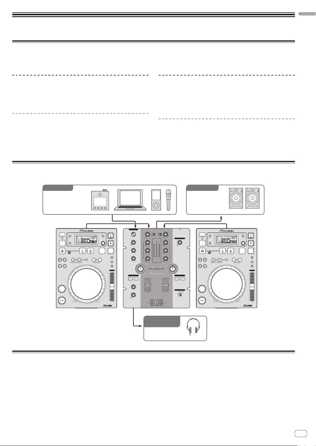
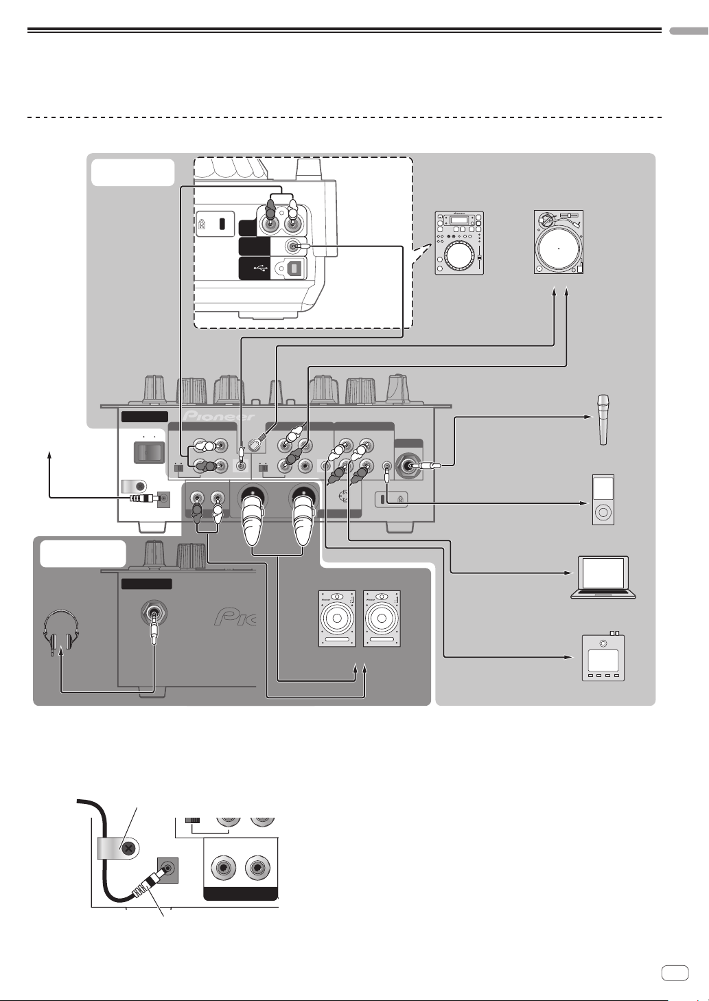
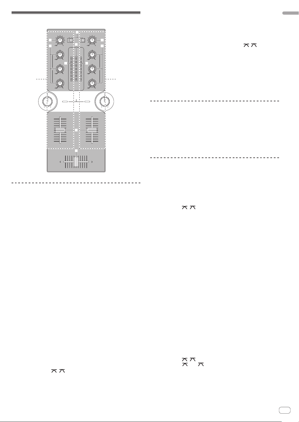
System setup example
A DJ system like the one shown on the diagram below can be achieved by combining this unit with a DJ player and peripheral equipment.
Synthesizers,
computers,
portable audio devices,
microphones, etc.
TIME MODE
REMAIN
AUTO CUE
A.CUE
INFO
DISPLAY
BROWSE
USB
STOP
UTILITY
SOURCE SELECT
MP3/AAC
WAV/AIFF
IN/CUEOUT
TRACK SEARCH
OUT ADJUSTHOT LOOP
SEARCH
CUE
PLAY/PAUSE
REVFWD
MIC/AUX
OFF
TRIM
MS
RELOOP/EXIT
LOOP
FTEMPO %
LOCK
BEAT LOOP
LOOP DRIVE
MIC
BACK
16
BPM
SELECT PUSH
DISC
BPM
PLAYLIST
LOCK
VINYL MODE
TEMPO RANGE
MASTER TEMPO
TEMPO
0
MULTI PLAYER
LEVEL
LOW
HEADPHONES
CH-1 CH-2
MIXING
LEVEL
PHONES
AUX 1
0
HI
MASTERCUE
0
PHONO
CD
CD
/LINE
AUX 2
AUX 3
9
HI
MASTER
CH-1 CH-2
OVER
OVER
9
+4
+4
MID
+2
+2
0
0
EQ EQ
-
6
-
6
9
1212
1212
-
12
-
12
LOW
-
18
-
18
dB
dB
LEVEL
9
SOUND COLOR FILTER
LPFHPF LPFHPF
CH-1 CH-2
CDJ-350, etc. DJM-250
For checking the
audio input/output
Headphones
For audio outputFor audio input
Powered speakers,
components,
amplifiers, etc.
ONOFF
TRIM
PHONO
2 CHANNEL DJ MIXER
/LINE
DJM-250
9
MASTER LEVEL
HI
0
9
MID
9
LOW
9
FADER START
CH-1 CH-2
CROSS FADER
THRU
USB
STOP
TRACK SEARCH
SEARCH
CUE
PLAY/PAUSE
TIME MODE
AUTO CUE
DISPLAY
UTILITY
SOURCE SELECT
REMAIN
A.CUE
INFO
BROWSE
MP3/AAC
WAV/AIFF
IN/CUEOUT
OUT ADJUSTHOT LOOP
REVFWD
HDJ-500, etc.
MS
RELOOP/EXIT
F TEMPO %
16
LOCK
BPM
BEAT LOOP
LOOP
LOOP DRIVE
CDJ-350, etc.
INPUT
1
2
34EQ
POWER
S-DJ05, etc.
BACK
SELECT PUSH
DISC
BPM
PLAYLIST
LOCK
VINYL MODE
TEMPO RANGE
MASTER TEMPO
TEMPO
0
MULTI PLAYER
INPUT
1
2
34EQ
POWER
What’s in the box
! AC adapter
! Power plug
! Operating instructions (this document)
En
5
Page 6
Connections
Be sure to turn off the power and unplug the AC adapter from the power outlet before making or changing connections between devices.
Wait until all connections between devices have been completed before connecting the AC adapter.
Only use the AC adapter included with this unit.
Refer to the operating instructions for the component to be connected.
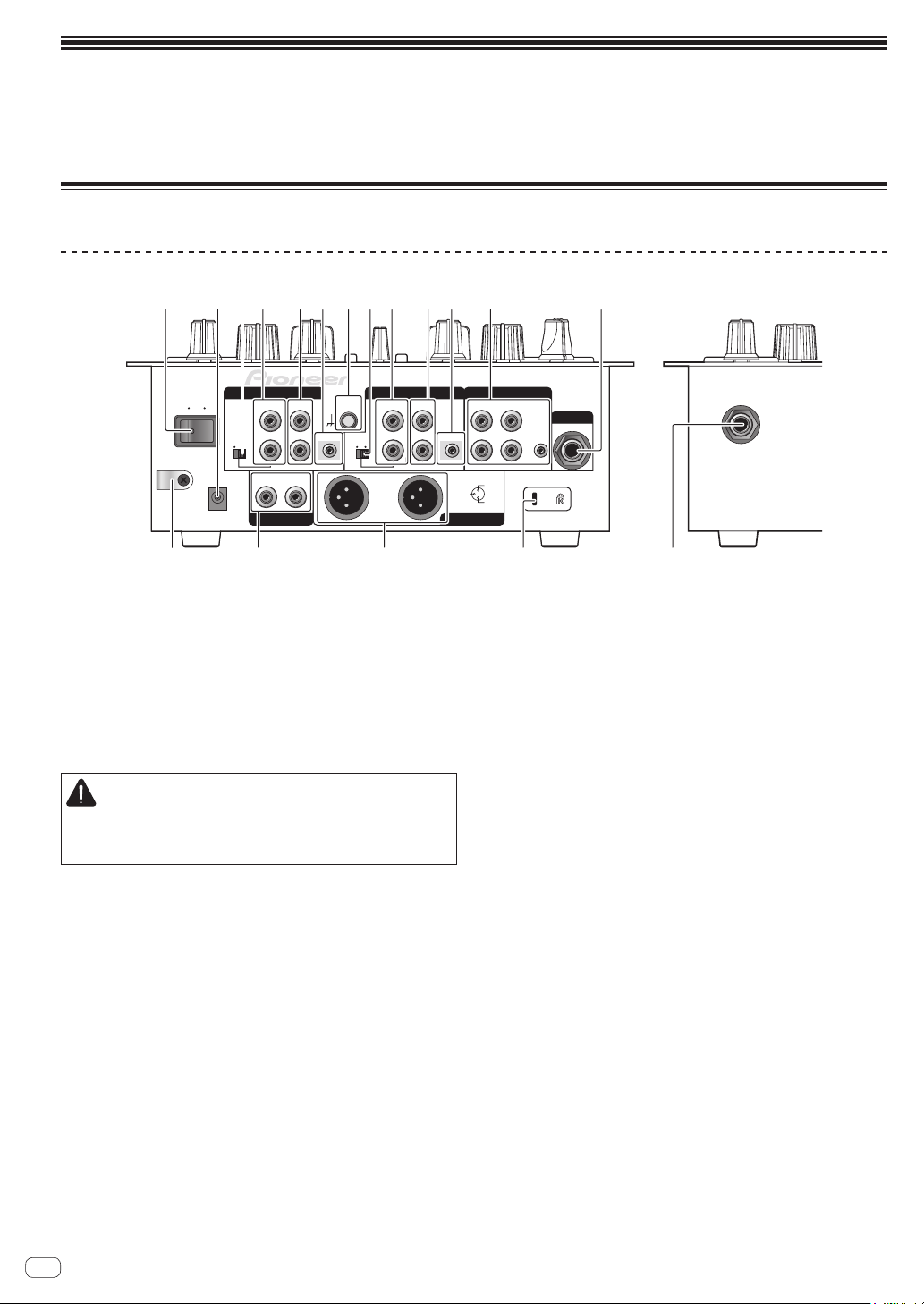
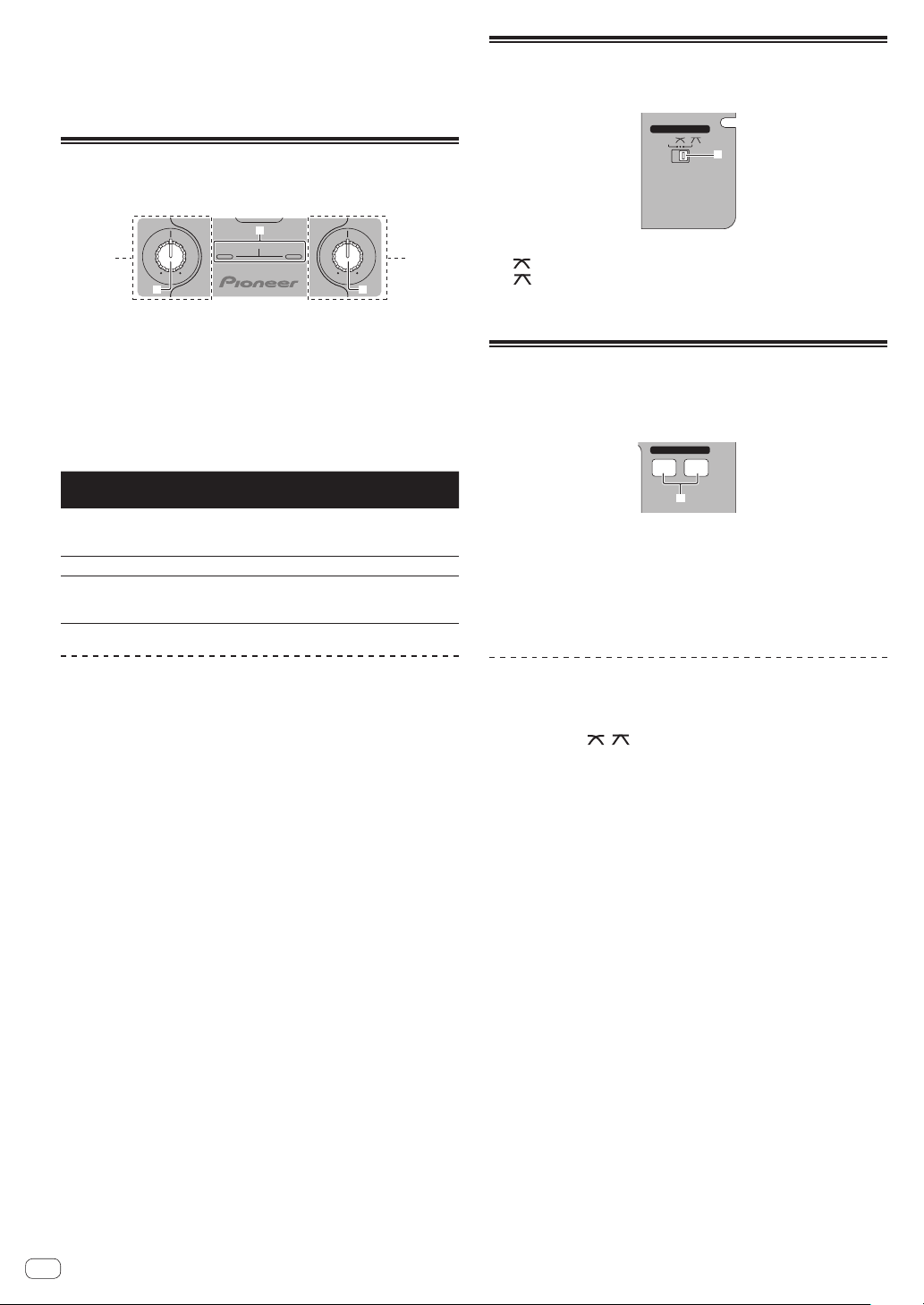
Names of Parts
Rear panel, front panel
321 4 5 86 4 5 67 3 9
CH-2
ON
PHONO / LINE CD
OFF
LINE PHONO
DC IN
L
R
RL
SIGNAL
PHONO / LINE CD
GND
CONTROL
LINE PHONO
L
R
b dc a
1 ON/OFF switch (page 10)
Turns this unit’s power on and off.
2 DC IN terminal
Connect to a power outlet using the included AC adapter (with the
power plug mounted).
Wait until connection of all equipment is completed before connecting the AC adapter.
Only use the included AC adapter.
3 PHONO/LINE selector switch (page 7)
Switches the function of the [PHONO/LINE] terminals.
CAUTION
When switching the [PHONO/LINE] selector switch, set
[MASTER LEVEL] to [-∞]. Note that noise may be generated and
sound output at a high volume.
4 PHONO/LINE terminals (page 7)
Connect a phono level output device (analog player (for MM cartridges), etc.) or a line level output device (DJ player, etc.) here.
Switch the terminals’ function according to the connected device
using the [PHONO/LINE] selector switch on this unit’s rear panel.
5 CD terminals (page 7)
Connect to a DJ player or other line level device.
6 CONTROL terminal (page 7)
Connect using a control cord (included with Pioneer DJ players).
7 SIGNAL GND terminal (page 7)
Connect an analog player’s ground wire here. This helps reduce
noise when the analog player is connected.
8 AUX terminals (page 7)
Connect to the output terminals of external devices (computers,
portable audio sets, TVs, synthesizers, etc.).
9 MIC terminal (page 7)
Connect to a microphone.
CH-1 AUX
L
CONTROL
R
3 COLD
MASTER 1MASTER 2
L
R
1GND
2 HOT
a MASTER 1 terminals (page 7)
b MASTER 2 terminals (page 7)
c Cord hook
d Kensington security slot
e PHONES jack (page 7)
23
MIC
1
e
Connect powered speakers, etc., here.
! Compatible with XLR connector type balanced outputs.
Connect powered speakers, etc., here.
! Compatible with RCA pin-jack type unbalanced outputs.
Hook the AC adapters’ power cord here.
Connect headphones here.
En
6
Page 7
Connecting the input/output terminals
Cord hook
! When creating a DVS (Digital Vinyl System) combining a computer, audio interface, etc., be careful in connecting the audio interface to this unit’s
input terminals and in the settings of the input selector switches.
Also refer to the operating instructions of the DJ software and audio interface.
Rear panel, front panel
English
To power outlet
AC adapter
(included)
Audio output
section
Headphones
Audio input
section
Rear panel
ON
OFF
Front panel
Audio cable
RL
L
R
AUDIO
OUT
CONTROL
USB
CH-2
PHONO / LINE
LINE PHONO
RL
DC IN
R
SIGNAL
CD
GND
L
L
CONTROL
R
R
L
R
L
PHONO / LINE
LINE PHONO
CH-1 AUX
CD
L
L
CONTROL
R
R
Powered speaker, component,
Control cord
L
LL
R
R R
1GND
3 COLD
2 HOT
MASTER 1MASTER 2
amplifier, etc.
INPUT
1
2
34EQ
POWER
Example:
CDJ-350
23
1
Analog playerDJ player
1
To ground wire
terminals
To audio output
terminals
Ground wire
Audio cable
Microphone
Microphone cable
To microphone
MIC
Portable audio
device
Audio cable
To audio output
terminals
Computer
Audio cable
To audio output
INPUT
1
2
34EQ
POWER
terminals
synthesizer
To audio input terminals
Headphones
cord
Audio cable
Audio cable
1 To use the fader start function, connect a control cord (page 12).
The fader start function can only be used when connected to a Pioneer DJ player.
Cord hook
Loosen the cord hook’s screw and pinch the AC adapters’
power cord under the hook.
R
DC IN
AC adapter’ s power cord
! Place the cord hook out of reach of children. If a child should
swallow it, contact a physician immediately.
LR
MASTER 2
Audio cable
To audio output
terminals
En
7
Page 8
About the AC adapter
Coin, paper clip or other metal object
Safety instructions
To ensure your personal safety and to maximize the full operating potential of your unit, read and follow these safety instructions.
Read & Retain Instructions
Read all operating and user information provided with this product.
Cleaning
Use a damp cloth to clean the exterior housing. Avoid using any fluids
including liquid, aerosol or alcohol-based cleaning products.
Water or Moisture
Avoid operating or locating this product near water or other sources of
fluid.
Accessories
Do not place this product on an unstable cart, stand, or table. The product may fall and be seriously damaged.
Ventilation
Do not block or cover this product in use. This unit should not be placed
in a built-in installation unless properly ventilated.
Environment
Avoid placing this product in a location with exposure to large quantities
of dust, high temperatures, high humidity, or subject to excessive vibrations or shocks.
Power Sources
Operate this product only from the recommended power sources. If
you are unsure of the power source, consult an authorized Pioneer
representative.
Power-Cord Protection
When unplugging the unit, pull on the plug – not on the cord. Do not
handle the cord or plug with wet hands; doing so could cause an electric
short or shock. Do not allow anything to pinch or rest on the power cord
and do not place in a walkway.
Power
Turn OFF the system before installing this or any other hardware device.
Overloading
Avoid connecting too many devices to a single wall socket or power
source as this can cause fires or short circuits.
Object & Liquid Entry
Never push inappropriate objects in to the device. Avoid spilling any
liquids in to or on the outside of the drive.
Servicing
Opening or removing the cover exposes you to possible electrical shock
or other danger. Contact a Pioneer authorized service representative for
repairing this product (refer to the enclosed Service & Support Card).
Damage Requiring Service
Unplug the unit and refer servicing to qualified service personnel in the
following situations:
! When the power cord, plug, or chassis is damaged.
! If liquid has been spilled, or objects have fallen into the product.
! If the product has been exposed to rain or water.
! If the product does not operate normally when the operating instruc-
tions are followed. Adjust only those controls that are covered by the
operating instructions. Improper adjustment of other controls may
result in damage and can require extensive work by a qualified technician to restore the unit to its normal operation.
! When the product exhibits a distinct change in performance – this
indicates a need for service.
Check that there are no irregularities with the AC adapter or power plug,
then insert the power plug into the specified position of the AC adapter
using the specified procedure until a click is heard. For details, see
Mounting the power plug on page 9.
If there are irregularities with the AC adapter or power plug, ask your
nearest Pioneer authorized service center or your dealer to carry out
repair work.
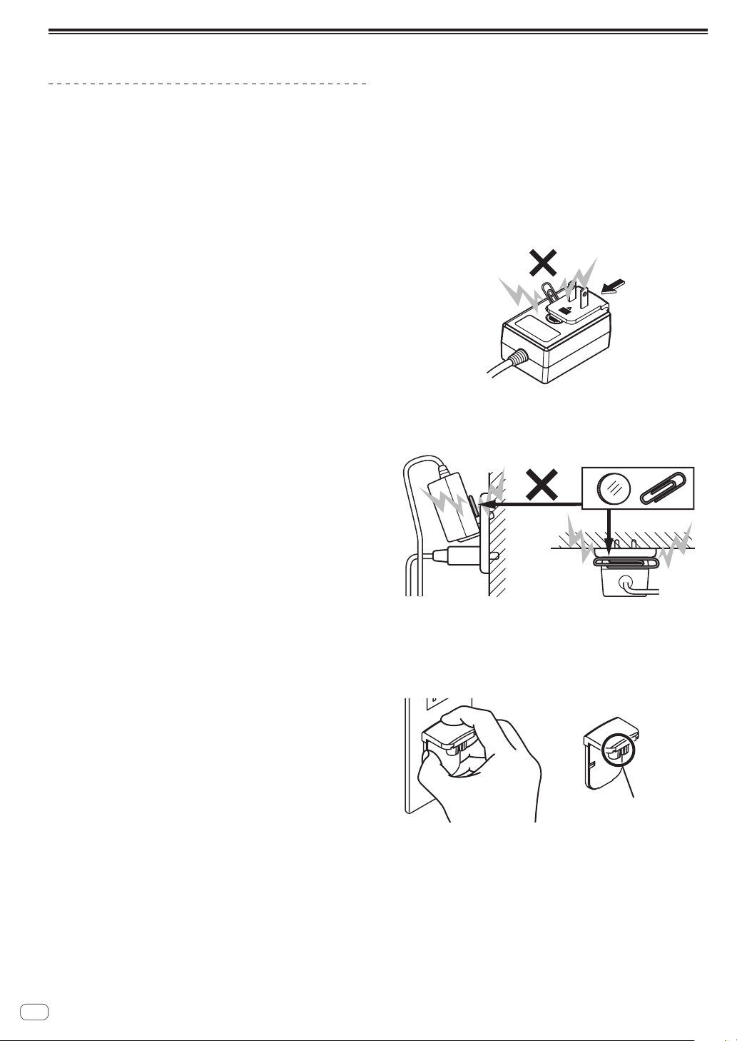
! Do not place the AC adapter cord around your neck. Doing so could
result in suffocation.
! Do not use this unit with a coin, paper clip or other metal object
stuck between the AC adapter and power plug. Doing so could cause
a short circuit, leading to fire or electric shock.
! When mounting the AC adapter on a wall outlet, make sure there is
no space between the AC adapter and the wall outlet. Faulty contact
or a coin, paper clip or other metal object getting stuck in the space
could cause a short circuit, leading to fire or electric shock.
Side
! The power plug could come detached from the AC adapter and
remain in the power outlet if someone trips on the AC adapter’s
power cord or if something hits the AC adapter. If this happens,
remove the power plug remaining in the outlet with dry hands, holding it as shown on the diagram below and without touching metal
parts. Do not use any tools to remove it.
Do not touch.
Top
En
8
Page 9
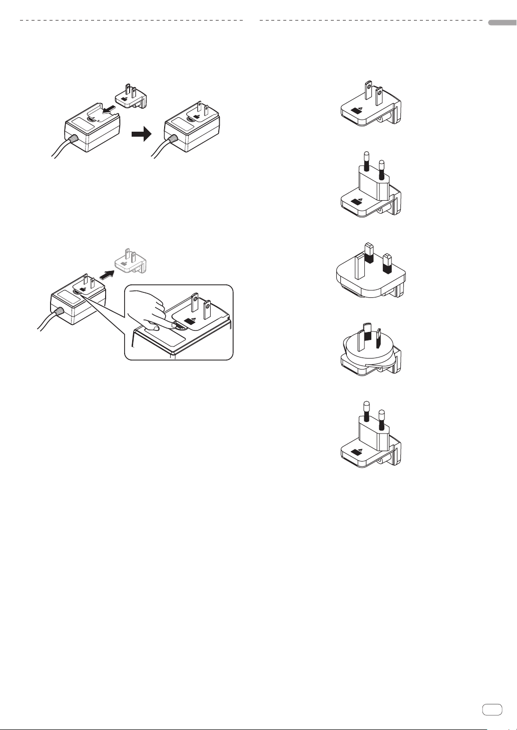
Mounting the power plug
Slide the power plug along the guide rails in the AC
adapter unit as shown on the diagram below, then press
in until a click is heard.
Removing the power plug
While pressing the [PUSH] button on the AC adapter
unit, slide the power plug away from the adapter as
shown on the diagram below to remove it.
Once the power plug is mounted, there is no need to remove it.
Power plug
This product comes with the types of power plugs shown below. Use the
appropriate power plug for the country or region you are in.
Type 1 (for Mexico, Taiwan, etc.)
Type 2
Type 3 (for Hong Kong, Malaysia, Singapore, etc.)
Type 4 (for Australia, New Zealand, etc.)
English
Type 5 (for Thailand, etc.)
En
9
Page 10
Operation
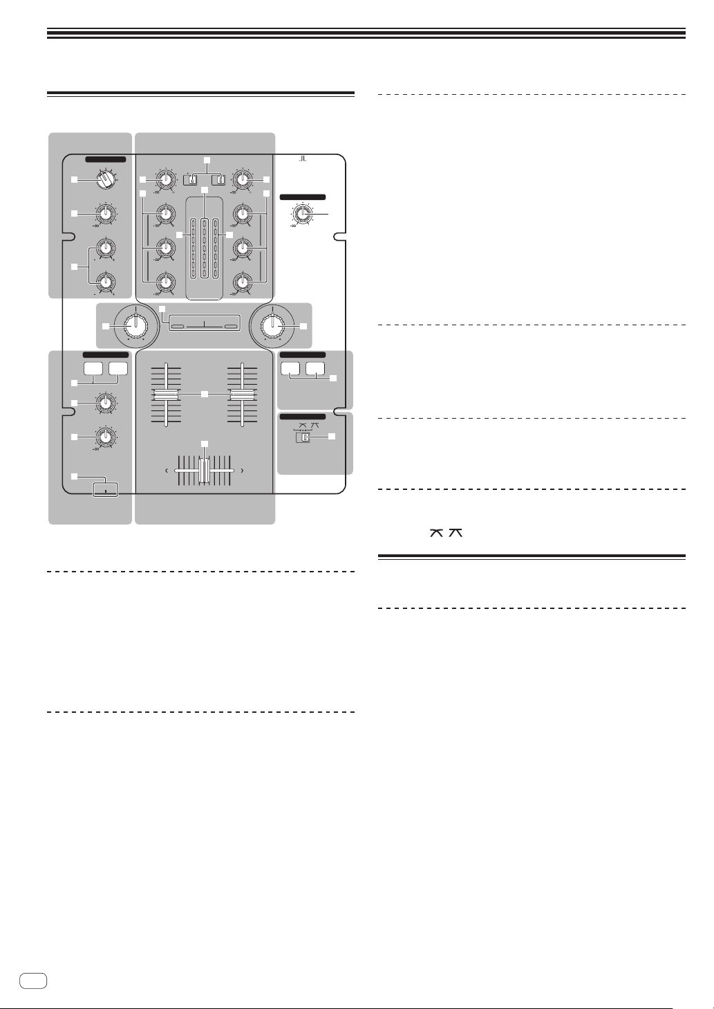
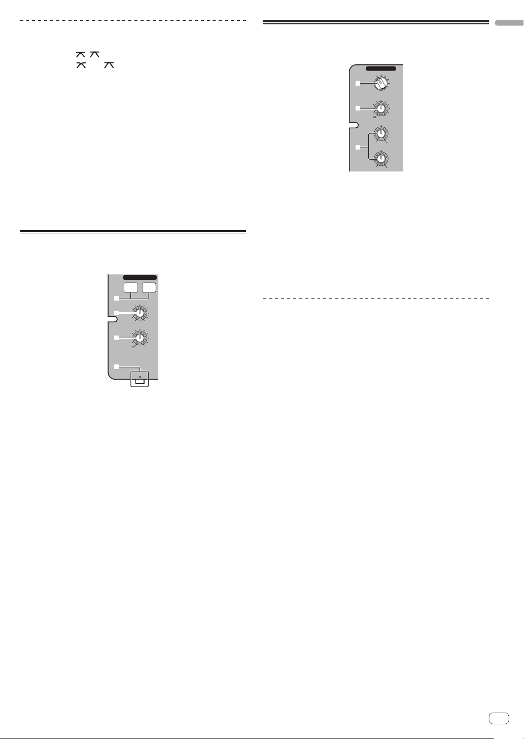
Control panel
MIC/AUX section Mixer section
MIC/AUX
OFF
MIC
AUX 1
AUX 2
LEVEL
LOW
AUX 3
b
0
HI
EQ EQ
1212
1212
2 a
3
4
g
LPFHPF LPF HPF
HEADPHONES
CH-1 CH-2
5
MIXING
6
7
8
Headphones
section
LEVEL
PHONES
MASTERCUE
CH-1 CH-2
0
1 MASTER LEVEL control (page 11)
TRIM
PHONO
CD
/LINE
c
9
HI
MASTER
CH-1 CH-2
OVER
9
+4
MID
d d
+2
0
-
6
9
-
12
LOW
-
18
dB
LEVEL
9
SOUND COLOR FILTER
Filter section
e
f
Mixer section
9
PHONO
CD
/LINE
OVER
+4
+2
0
-
6
-
12
-
18
dB
Mixer section
Two sets of audio signals can be adjusted separately for basic DJ mixing
(page 11).
TRIM
a
9
b
HI
9
MID
9
LOW
ONOFF
2 CHANNEL DJ MIXER
DJM-250
MASTER LEVEL
0
9 CD, PHONO/LINE input selector switch
a TRIM control
1
b EQ (HI, MID, LOW) control
c Master level indicator
d Channel level indicator
e Channel fader
9
hh
f Crossfader
Filter section
FADER START
CH-1 CH-2
Fader start
section
CROSS FADER
THRU
Crossfader
section
i
j
g SOUND COLOR FILTER indicator
h SOUND COLOR FILTER control
Fader start section
i CH-1, CH-2 buttons (fader start section)
Crossfader section
j THRU, , (crossfader curve selector switch)
MIC/AUX section
This section handles the sound of microphones or external devices
(computers, portable audio sets, TVs, synthesizers, etc.) (page 13).
2 MIC, OFF, AUX 1, AUX 2, AUX 3 input selector switch
3 LEVEL control (MIC/AUX section)
4 HI, LOW controls
Headphones section
The sound being input to this unit can be checked over headphones
(page 13).
5 CH-1, CH-2 buttons (headphones section)
6 MIXING control
7 LEVEL control (headphones section)
8 PHONES jack
About the power switch of this unit
To turn the power on
Set the [ON/OFF] switch on this unit’s rear panel to [ON].
This turns this unit’s power on (page 6).
10
En
Page 11
Basic operations (mixer section)
PHONO
CD
/LINE
9
HI
MASTER
CH-1 CH-2
OVER
9
MID
d d
9
-
-
dB
LEVEL
9
SOUND COLOR FILTER
9
TRIM
PHONO
CD
/LINE
c
OVER
+4
+4
+2
+2
0
0
-
6
-
6
12
-
12
18
-
18
dB
a
9
b
HI
9
MID
9
LOW
9
e
f
TRIM
a
b
EQ EQ
1 2
LOW
LPFHPF LPFHPF
CH-1 CH-2
Outputting sound
Check that this unit is properly connected to the DJ player, etc., before
outputting sound. For instructions on connections, see Connecting the
input/output terminals on page 7.
Set the volume of the powered speakers connected to the [MASTER 1]
and [MASTER 2] terminals to a suitable level. Note that sound will be
output at a high volume if the volume is set too high.
For instructions on monitoring the sound, see Monitoring the sound over
headphones (headphones section) on page 13.
To output the sound of channel 1 [CH-1] 1
To output the sound of channel 2 ([CH-2]) 2, perform the procedure
below replacing [CH-1] with [CH-2].
1 Switch the [CH-1] 1 [CD, PHONO/LINE] input selector
switch 9.
Select the input source for [CH-1] from among the devices connected to
this unit.
— [CD]: Selects the DJ player connected to the [CD] terminals.
— [PHONO/LINE]: Selects the device connected to the
[PHONO/LINE] terminals.
2 Turn the [CH-1] 1 [TRIM] control a clockwise.
Adjusts the audio level input to the [CH-1] terminal.
The [CH-1] channel level indicator d lights when audio signals are being
properly input to [CH-1].
Adjust the [TRIM] control so that the orange indicator lights where the
track’s volume is highest (at the climax, etc.)
Be careful that the red indicator does not light, or the sound could be
distorted.
3 Move the [CH-1] 1 channel fader e away from you.
The level of the sound output from the [CH-1] terminals is adjusted.
4 Switch [THRU, , ] (the crossfader curve selector
switch) j.
This switches the crossfader’s curve characteristics. For details, see
Selecting the crossfader’s curve characteristics (crossfader section) on
page 12.
5 Move the crossfader f.
Switch the channel whose sound is output from the speakers.
— Left edge: The [CH-1] sound is output.
— Center position: The sound of [CH-1] and [CH-2] is mixed and
output.
— Right edge: The [CH-2] sound is output.
! This operation is not necessary when the [THRU,
, ] (cross-
fader curve selector) switch is set to [THRU].
6 Turn the [MASTER LEVEL] control 1 clockwise.
Sound is output from the speakers.
The master level indicator c on the control panel lights.
Adjust [MASTER LEVEL] so that the orange indicator lights at the point
in the track where the volume is loudest (the climax, etc.).
Be careful that the red indicator does not light, or the sound could be
distorted.
Adjusting the sound quality
Turn the [CH-1] 1 or [CH-2] 2 EQ (HI, MID, LOW) control
b.
Refer to Specifications on page 15 for the range of sound that can be
adjusted by each control.
! The sound for that range can be turned completely off by turning the
control all the way counterclockwise (isolator function).
Mixing using the faders
Prepare the unit in advance so that the sound of [CH-1] 1 is being output from the speakers. For instructions on preparation, see Outputting
sound on page 11.
Mixing using the channel faders
1 Set [THRU,
switch) j to [THRU].
2 Switch the [CH-2] 2 [CD, PHONO/LINE] input selector
switch 9.
3 Turn the [CH-2] 2 [TRIM] control a clockwise.
4 Press the [CH-2] button 5 in the headphones section.
The sound of [CH-2] is monitored from the headphones.
5 Turn the [MIXING] control 6.
Adjust the monitor volume balance of the sound output from the
[MASTER 1] or [MASTER 2] terminals (the [CH-1] sound) and the [CH-2]
sound.
6 Operate the DJ player connected to the [CH-2]
terminals.
While checking the sound over the headphones, adjust the tempo of
[CH-2] track to match the tempo of [CH-1] track.
7 While moving the [CH-2] 2 channel fader to the back,
move the [CH-1] 1 channel fader to the front.
While checking the sound output from the speakers, operate the channel faders to substitute the sound of [CH-1] with the sound of [CH-2].
Mixing is completed once only the [CH-2] sound is being output from the
speakers.
Mixing using the crossfader
1 Set [THRU,
switch) j to [ ] or [ ].
2 Operate [CH-2] 2.
Operate as described in steps 2 to 6 under Mixing using the channel
faders on page 11.
, ] (the crossfader curve selector
, ] (the crossfader curve selector
English
En
11
Page 12
3 Move the crossfader f gradually towards the right.
While checking the sound output from the speakers, operate the crossfader to substitute the sound of [CH-1] with the sound of [CH-2].
Mixing is completed once only the [CH-2] sound is being output from the
speakers.
Using the filter function (filter
section)
g
1 2
LPFHPF LPF HPF
Each channel is equipped with a SOUND COLOR FILTER function by
which filter effects can be achieved simply by turning a large control.
The treble or bass sound can be removed by turning the
[SOUND COLOR FILTER] control h.
Turn the [CH-1] 1 or [CH-2] 2 [SOUND COLOR FILTER]
control h.
The effect is applied to the sound and the indicator’s color changes.
The effect type and indicator color differs according to the direction in
which the [FILTER] control is turned, as shown on the table below.
Direction of
rotation
Left
Center — Orange (lit)
Right
Description of effect Indicator
Applies the effect of the
treble sound fading out.
(LPF: low pass filter)
Applies the effect of the bass
sound fading out.
(HPF: high pass filter)
SOUND COLOR FILTER
hh
Red (flashing)
Green (flashing)
Selecting the crossfader’s curve
characteristics (crossfader section)
CROSS FADER
THRU
j
— [THRU]: Choose this when you do not want to use the crossfader.
]: Set here for a curve that rises gradually.
— [
— [ ]: Set here for a curve that rises steeply. (When the crossfader
moves away from either the left or right edge, the sound is immediately output from the opposite side.)
Starting playback of a Pioneer DJ
player using the fader (fader start
section)
FADER START
CH-1 CH-2
i
If you connect a Pioneer DJ player using a control cable (supplied with
a DJ player), you can start playback of control other operations of the DJ
player with the fader of this unit.
The fader start function can only be used when connected to a Pioneer
DJ player.
Connect this unit and Pioneer DJ player beforehand. For instructions on
connections, see Connecting the input/output terminals on page 7.
Mixing using the SOUND COLOR FILTER
control
Prepare the unit in advance so that the sound of [CH-1] 1 is being output from the speakers. For instructions on preparation, see Outputting
sound on page 11.
For instructions on monitoring the sound, see Monitoring the sound over
headphones (headphones section) on page 13.
1 Operate the crossfader and [CH-2] 2.
Operate as described in steps 2 to 6 under Mixing using the channel
faders on page 11.
2 Turn the [CH-2] 2 [SOUND COLOR FILTER] control h
fully clockwise.
3 Move the [CH-2] 2 channel fader e away from you.
4 While turning the [CH-1] 1 [SOUND COLOR FILTER]
control h counterclockwise from the center, turn the
[CH-2] 2 [SOUND COLOR FILTER] control h towards the
center.
While checking the sound output from the speakers, operate the
[SOUND COLOR FILTER] controls h and replace the [CH-1] and [CH-2]
sound.
Move the [CH-1] 1 channel fader e towards the front. Mixing is completed once only the sound of [CH-2] is output from the speakers.
To start playback using the channel
faders
1 Set [THRU, , ] (the crossfader curve selector
switch) j to [THRU].
2 Press the [CH-1] or [CH-2] button i in the fader start
section.
Turn the fader start function on.
3 Move the channel fader e to the very front.
4 Set the cue on the DJ player.
The DJ player pauses playback at the cue point.
5 Move the channel fader e away from you.
Playback starts on the DJ player.
! If you set the channel fader back to the original position, the player
instantaneously returns to the cue point already set and pauses
playback (back cue).
12
En
Page 13
To start playback using the crossfader
1 Set [THRU, , ] (the crossfader curve selector
switch) j to [ ] or [ ].
2 Press the [CH-1] or [CH-2] button i in the fader start
section.
Turn the fader start function on.
3 Move the crossfader f.
Move the crossfader to the opposite edge from the channel for which
you want to use the fader start function.
4 Set the cue on the DJ player.
The DJ player pauses playback at the cue point.
5 Move the crossfader f.
Playback starts on the DJ player.
! If you set the crossfader back to the original position, the player
instantaneously returns to the cue point already set and pauses
playback (back cue).
Monitoring the sound over
headphones (headphones section)
HEADPHONES
CH-1 CH-2
5
MIXING
6
7
8
LEVEL
PHONES
MASTERCUE
0
Using a microphone or external
device (MIC/AUX section)
MIC/AUX
OFF
MIC
AUX 1
AUX 2
LEVEL
LOW
AUX 3
0
HI
1212
1212
2
3
4
1 Switch the [MIC, OFF, AUX 1, AUX 2, AUX 3] input
selector switch 2.
— [MIC]: The microphone connected to the [MIC] terminal is
selected.
— [AUX1–3]: Selects the external device connected to the [AUX1–3]
terminals.
2 Turn the [LEVEL] control 3 in the MIC/AUX section
clockwise.
The sound of the microphone or external device is output from the
speakers.
Adjusting the sound quality
Turn the [HI] or [LOW] control 4 in the MIC/AUX section.
Refer to Specifications on page 15 for the range of sound that can be
adjusted by each control.
English
1 Connect headphones to the [PHONES] terminal.
For instructions on connections, see Connecting the input/output terminals on page 7.
2 Press the [CH-1] or [CH-2] button 5 in the
headphones section.
Select the channel you want to monitor.
— [CH-1]: The sound of [CH-1] is monitored.
— [CH-2]: The sound of [CH-2] is monitored.
! This operation is not necessary to monitor the [MASTER 1] or
[MASTER 2] (master channel) sound.
3 Turn the [MIXING] control 6.
— When turned counterclockwise: The volume of [CH-1] and [CH-2]
becomes relatively louder.
— Center position: The volume of the [CH-1] and [CH-2] sound is
the same level as the [MASTER 1] and [MASTER 2] sound.
— When turned clockwise: The volume of [MASTER 1] and
[MASTER 2] become relatively louder.
4 Turn the [LEVEL] control 7 in the headphones section
clockwise.
Sound is output from the headphones.
! When the [CH-1] or [CH-2] button in the headphones section is
pressed again, monitoring is canceled.
! [MASTER 1] and [MASTER 2] monitoring cannot be canceled.
En
13
Page 14
Additional information
CD1
Troubleshooting
! Incorrect operation is often mistaken for trouble or malfunction. If you think that there is something wrong with this component, check the points
below. Sometimes the trouble may lie in another component. Inspect the other components and electrical appliances being used. If the trouble
cannot be rectified after checking the items below, ask your nearest Pioneer authorized service center or your dealer to carry out repair work.
! This unit may not operate properly due to static electricity or other external influences. In this case, proper operation may be restored by turning the
power off, waiting 1 minute, then turning the power back on.
Problem Check Remedy
The power is not turned on. Is the included AC adapter properly connected? Connect the included AC adapter properly to the power outlet. (page 7)
Properly attach the included AC adapter’s power cord to this unit’s cord hook.
(Page 7)
Is the [ON/OFF] switch for power supply set to
[ON]?
No sound or small sound. Is the [CD, PHONO/LINE] input selector switch set
Distorted sound. Is [MASTER LEVEL] set at the proper position? Adjust the [MASTER LEVEL] control so that the master level indicator’s orange
Can’t crossfade.
Can’t fader start a DJ player. Is the [CH-1] or [CH-2] button in the fader start
Sound is distorted when an analog
player is connected to this unit’s
[PHONO/LINE] terminals.
Or, lighting of the channel level
indicator does not change even when
the [TRIM] control is turned.
to the proper position?
Is the [PHONO/LINE] selector switch on this unit’s
rear panel set to the proper position?
Are the [TRIM], [channel fader], [crossfader]
and [MASTER LEVEL] controls set to the proper
positions?
Are the connected powered speakers, etc., properly set?
Are the connection cables properly connected? Connect the connection cables properly. (page 7)
Are the terminals and plugs dirty? Clean the terminals and plugs before making connections.
Is [TRIM] set at the proper position? Adjust the [TRIM] control so that the channel level indicator’s orange indicator
Is the [THRU,
switch set to [THRU]?
section set to the off position?
Is the control cord properly connected? Connect this unit and DJ player with a control cord. (page 7)
Are the audio cables properly connected? Connect this unit to the audio output terminal of a DJ player with an audio cable.
Have you connected an analog player with a builtin phono equalizer?
Is an audio interface for computers connected
between the analog player and this unit?
, ] (crossfader curve selector)
Set the [ON/OFF] switch for power supply to [ON]. (Page 10)
Switch the [CD, PHONO/LINE] input selector switch to the channel’s input
source. (Page 11)
Switch the terminals’ function using the [PHONO/LINE] selector switch on this
unit’s rear panel. (Page 6)
Set the [TRIM], [channel fader], [crossfader] and [MASTER LEVEL] controls to
the proper positions. (Page 11)
Properly set the external input selection, volume, etc., on the powered speakers,
etc.
indicator lights at the peak level. (Page 11)
lights at the peak level. (Page 11)
Set the [THRU, , ] (crossfader curve selector) switch to a position other
than [THRU]. (Page 11)
Set the [CH-1] or [CH-2] button in the fader start section to the on position. (page
12)
(page 7)
If the analog player is equipped with a built-in phono equalizer, connect it to the
[CD] terminals. (page 7)
If the analog player with built-in phono equalizer has a PHONO/LINE selector
switch, switch it to PHONO.
If the computer audio interface’s output is line level, connect it to the [CD]
terminals. (page 7)
If the analog player has a PHONO/LINE selector switch, switch it to PHONO.
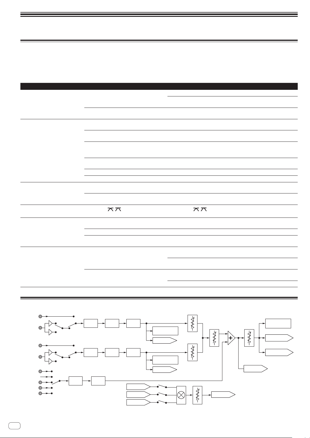
Block Diagram
LINE1/
PHONO1
CD2
LINE2/
PHONO2
MIC
OFF
AUX 1
AUX 2
AUX 3
En
14
LEVEL
TRIM
TRIM
2Band
EQ
3Band
EQ
3Band
EQ
FILTER
FILTER
HP MASTER
HP CH 1 HP OUT
HP CH 2
CH 1
LEVEL METER
HP CH 1
CH 2
LEVEL METER
HP CH 2
HP MIX
CH 1
FADER
CH 2
FADER
HP VOL
CROSS
FADER
MASTER
VOL
HP MASTER
MASTER LEVEL
METER
MASTER 1 OUT
MASTER 2 OUT
Page 15

About trademarks and registered
trademarks
! Pioneer is a registered trademark of PIONEER CORPORATION.
! The names of companies and products mentioned herein are the
trademarks of their respective owners.
! When playing music files you have acquired on this unit, we kindly
ask you to respect copyrights.
Specifications
AC adapter
Power ............................................................ AC 100 V to 240 V, 50 Hz/60 Hz
Rated current ..................................................................................... 800 mA
Rated output ................................................................................. DC 5 V, 3 A
General – Main Unit
Main unit weight ................................................................................... 3.1 kg
Max. external dimensions ................................240 mm (width) x 107.7 mm
(height) x 300.2 mm (depth)
Tolerable operating temperature ........................................ +5 °C to +35 °C
Tolerable operating humidity ...................... 5 % to 85 % (no condensation)
Audio Section
Sampling rate .......................................................................................48 kHz
A/D, D/A converter ...............................................................................24 bits
Frequency characteristic
CD/LINE/AUX/MIC ......................................................... 20 Hz to 20 kHz
S/N ratio (rated output)
CD .................................................................................................... 91 dB
LINE ................................................................................................. 91 dB
PHONO............................................................................................ 86 dB
MIC .................................................................................................. 80 dB
Total harmonic distortion (CD — MASTER 1) ..................................0.007 %
Standard input level / Input impedance
CD ..................................................................................... –12 dBu/10 kW
LINE .................................................................................. –12 dBu/47 kW
PHONO............................................................................. –48 dBu/47 kW
MIC ................................................................................... –52 dBu/10 kW
AUX 1 ............................................................................... –12 dBu/10 kW
AUX 2, 3 ........................................................................... –12 dBu/10 kW
Standard output level / Load impedance / Output impedance
MASTER 1 ..............................................................+6 dBu/10 kW/330 W
MASTER 2 ................................................................+2 dBu/10 kW/1 kW
PHONES .....................................................................+2 dBu/32 W/33 W
Rated output level / Load impedance
MASTER 1 .......................................................................+22 dBu/10 kW
MASTER 2 .......................................................................+18 dBu/10 kW
Crosstalk (CD) ....................................................................................... 74 dB
Channel equalizer characteristic
HI .......................................................................... –∞ to + 9 dB (13 kHz)
MID ......................................................................... –∞ to + 9 dB (1 kHz)
LOW ........................................................................ –∞ to +9 dB (70 Hz)
MIC/AUX equalizer characteristics
HI ...................................................................–12 dB to +12 dB (10 kHz)
LOW ..............................................................–12 dB to +12 dB (100 Hz)
Input/output terminals
CD input terminal
RCA pin jack .................................................................................... 2 sets
PHONO/LINE input terminals
RCA pin jack .................................................................................... 2 sets
MIC input terminal
Phone jack (Ø 6.3 mm) ..................................................................... 1 set
AUX input terminal
RCA pin jack .................................................................................... 2 sets
Mini phone jack (Ø 3.5 mm) ............................................................. 1 set
MASTER output terminal
RCA pin jacks ....................................................................................1 set
BALANCED OUTPUT output terminal
XLR connector...................................................................................1 set
PHONES output terminal
Stereo phone jack (Ø 6.3 mm) .........................................................1 set
CONTROL terminal
Mini phone jack (Ø 3.5 mm) ........................................................... 2 sets
! The specifications and design of this product are subject to change
without notice.
! © 2011 PIONEER CORPORATION. All rights reserved.
English
En
15
Page 16

Le damos las gracias por la adquisición de este producto Pioneer. Lea a fondo estas instrucciones de utilización para que aprenda a utilizar correcta-
ADVERTENCIA
mente su modelo. Después de haber terminado de leer estas instrucciones, guárdelas en un lugar seguro para, en caso de ser necesario, consultarlas
en el futuro.
En algunos países o regiones, la forma de la clavija de alimentación y del enchufe de corriente pueden ser diferentes de la mostrada en las ilustraciones de explicación. Sin embargo, el método de conexión y operación del aparato es el mismo.
Este aparato no es impermeable. Para evitar el riesgo
de incendio y de descargas eléctricas, no ponga ningún
recipiente lleno de líquido (como pueda ser un vaso o
un florero) cerca del aparato ni lo exponga a goteo,
salpicaduras, lluvia o humedad.
ADVERTENCIA
Antes de enchufar el aparato a la corriente, lea la sección
siguiente con mucha atención.
La tensión de la red eléctrica es distinta según el
país o región. Asegúrese de que la tensión de la
alimentación de la localidad donde se proponga
utilizar este aparato corresponda a la tensión
necesaria (es decir, 230 V ó 120 V) indicada en el
panel lateral.
ADVERTENCIA
Para evitar el peligro de incendio, no ponga nada con
fuego encendido (como pueda ser una vela) encima del
aparato.
Entorno de funcionamiento
Temperatura y humedad del entorno de funcionamiento
+5 °C a +35 °C; menos del 85 % de humedad relativa
(rejillas de refrigeración no obstruidas)
No instale este aparato en un lugar mal ventilado, ni en
lugares expuestos a alta humedad o a la luz directa del
sol (o de otra luz artificial potente).
Este producto es para tareas domésticas generales.
Cualquiera avería debida a otra utilización que tareas
domésticas (tales como el uso a largo plazo para
motivos de negocios en un restaurante o el uso en un
coche o un barco) y que necesita una reparación
hará que cobrarla incluso durante el período de
garantía.
D3-4-2-1-3_A1_Es
D3-4-2-1-4*_A1_Es
D3-4-2-1-7a_A1_Es
D3-4-2-1-7c*_A1_Es
K041_A1_Es
PRECAUCIÓN
El interruptor de la alimentación ON/OFF de este
aparato no corta por completo toda la alimentación
de la toma de corriente de CA. Puesto que el cable de
alimentación hace las funciones de dispositivo de
desconexión de la corriente para el aparato, para
desconectar toda la alimentación del aparato deberá
desenchufar el cable de la toma de corriente de CA.
Por lo tanto, asegúrese de instalar el aparato de
modo que el cable de alimentación pueda
desenchufarse con facilidad de la toma de corriente
de CA en caso de un accidente. Para evitar correr el
peligro de incendio, el cable de alimentación también
deberá desenchufarse de la toma de corriente de CA
cuando no se tenga la intención de utilizarlo durante
mucho tiempo seguido (por ejemplo, antes de irse de
vacaciones).
D3-4-2-2-2a*_A1_Es
PRECAUCIONES CONCERNIENTES A LA
MANIPULACIÓN DEL CABLE DE
ALIMENTACIÓN
Tome el cable de alimentación por la clavija. No
extraiga la clavija tirando del cable. Nunca toque el
cable de alimentación cuando sus manos estén
mojadas, ya que esto podría causar cortocircuitos o
descargas eléctricas. No coloque la unidad, algún
mueble, etc., sobre el cable de alimentación.
Asegúrese de no hacer nudos en el cable ni de unirlo a
otros cables. Los cables de alimentación deberán ser
dispuestos de tal forma que la probabilidad de que
sean pisados sea mínima. Una cable de alimentación
dañado podrá causar incendios o descargas eléctricas.
Revise el cable de alimentación está dañado, solicite el
reemplazo del mismo al centro de servicio autorizado
PIONEER más cercano, o a su distribuidor.
S002*_A1_Es
Si la clavija del cable de alimentación de CA de este
aparato no se adapta a la toma de corriente de CA
que usted desea utilizar, deberá cambiar la clavija por
otra que se adapte apropiadamente. El reemplazo y
montaje de una clavija del cable de alimentación de
CA sólo deberá realizarlos personal de servicio
técnico cualificado. Si se enchufa la clavija cortada a
una toma de corriente de CA, puede causar fuertes
descargas eléctricas. Asegúrese de que se tira de la
forma apropiada después de haberla extraído.
El aparato deberá desconectarse desenchufando la
clavija de la alimentación de la toma de corriente
cuando no se proponga utilizarlo durante mucho
tiempo (por ejemplo, antes de irse de vacaciones).
Es
2
D3-4-2-2-1a_A1_Es
Page 17

Contenido
Cómo leer este manual
Los nombres de las visualizaciones, menús y botones de este manual
van entre corchetes. (p. ej.: Canal [MASTER], [ON/OFF], menú [File])
Antes de empezar a usar la unidad
Características ............................................................................................ 4
Ejemplo de configuración del sistema ..................................................... 4
Contenido de la caja ................................................................................... 4
Conexiones
Nombres de las partes ............................................................................... 5
Conexión de los terminales de entrada/salida ......................................... 6
Acerca del adaptador de CA ...................................................................... 7
Operación
Panel de control .......................................................................................... 9
Acerca del interruptor de alimentación de esta unidad ......................... 9
Operaciones básicas (sección del mezclador) ...................................... 10
Uso de la función de filtro (sección de filtro) ......................................... 11
Selección de las características de curva de crossfader
(sección de crossfader) ............................................................................ 11
Inicio de reproducción en un reproductor DJ de Pioneer
usando el fader (sección de inicio de fader) .......................................... 11
Monitoreo del sonido con los auriculares (sección de auriculares).... 12
Utilizando un micrófono o aparato externo (Sección MIC/AUX) ......... 12
Información adicional
Solución de problemas ............................................................................ 13
Diagrama en bloques ............................................................................... 14
Acerca de las marcas de fábrica y marcas registradas ........................ 14
Especificaciones ....................................................................................... 14
Es
3
Page 18

Antes de empezar a usar la unidad
Características
Esta unidad es un mezclador DJ que emplea la tecnología de la serie DJM de Pioneer, la norma mundial en sonido de clubes. La unidad es del tipo
estándar, equipada con las funciones básicas necesarias para mezclar sonidos, lo que permite al DJ realizar una reproducción completa.
SOUND COLOR FILTER
Cada canal está equipado con una función SOUND COLOR FILTER
por la cual pueden obtenerse efectos de filtro girando simplemente un
control grande. Esto le permite organizar y mezclar pistas intuitivamente
para actuaciones de DJ.
MIC/AUX INPUT
Esta unidad está equipada con tres juegos de entradas AUX para introducir señales de audio de aparatos externos (ordenadores, aparatos
de audio portátiles, TV, sintetizadores, etc.) y también una entrada de
micrófono. No sólo se puede usar para actuaciones de DJ, sino también
como preamplificador para apreciar música.
ECUALIZADOR DE 3 BANDAS
Esta unidad está equipada con un ecualizador de 3 bandas que permite
ajustar por separado el volumen de las gamas de frecuencias altas,
medias y bajas. No sólo se puede ajustar el tono a su gusto, sino que
el sonido de cierta gama se puede apagar completamente girando el
control totalmente a la izquierda (función de aislador).
XLR OUTPUT
Esta unidad está equipada con salidas balanceadas XLR con muy poca
pérdida de calidad de la señal de audio, para lograr actuaciones de DJ
con alta calidad de sonido. También se puede conectar a altavoces con
amplificadores u otros aparatos compatibles con entradas XLR sin tener
que hacer ningún cambio en los terminales.
Ejemplo de configuración del sistema
Combinando esta unidad con un reproductor DJ y un equipo periférico se puede crear un sistema DJ como el mostrado en el diagrama de más abajo.
Sintetizador
Ordenador
Aparato de audio portátil,
Micrófono
TIME MODE
REMAIN
MS
AUTO CUE
A.CUE
INFO
DISPLAY
BROWSE
USB
STOP
UTILITY
SOURCE SELECT
MP3/AAC
WAV/AIFF
IN/CUE OUT
TRACK SEARCH
SEARCH
CUE
PLAY/PAUSE
RELOOP/EXIT
OUT ADJUSTHOT LOOP
REVFWD
MIC/AUX
OFF
TRIM
TRIM
PHONO
PHONO
CD
CD
/LINE
/LINE
9
HI
MID
EQ EQ
LOW
CH-1 CH-2
9
9
9
SOUND COLOR FILTER
HI
MASTER
OVER
OVER
+4
+4
MID
+2
+2
0
0
-
6
-
6
-
12
-
12
LOW
-
18
-
18
dB
dB
LEVEL
CH-1 CH-2
9
9
9
9
LOOP
FTEMPO %
LOCK
BPM
BEAT LOOP
LOOP DRIVE
MIC
AUX 1
BACK
16
SELECT PUSH
DISC
BPM
PLAYLIST
LOCK
VINYL MODE
TEMPO RANGE
MASTER TEMPO
TEMPO
0
MULTI PLAYER
AUX 2
AUX 3
LEVEL
0
HI
1212
LOW
1212
LPFHPF LPFHPF
HEADPHONES
CH-1 CH-2
MIXING
MASTERCUE
LEVEL
0
PHONES
CDJ-350, etc. DJM-250
Para comprobar la
entrada/salida de audio
Auriculares
Para salida de audioPara entrada de audio
altavoces con amplificador,
componentes,
amplificadores, etc.
ONOFF
2 CHANNEL DJ MIXER
DJM-250
MASTER LEVEL
FADER START
CH-1 CH-2
CROSS FADER
THRU
0
USB
STOP
TRACK SEARCH
SEARCH
CUE
PLAY/PAUSE
HDJ-500, etc.
TIME MODE
REMAIN
MS
AUTO CUE
A.CUE
INFO
DISPLAY
BROWSE
UTILITY
SOURCE SELECT
MP3/AAC
WAV/AIFF
IN/CUE OUT
RELOOP/EXIT
OUT ADJUSTHOT LOOP
REVFWD
F TEMPO %
16
LOCK
BPM
BEAT LOOP
LOOP
LOOP DRIVE
CDJ-350, etc.
INPUT
1
2
34EQ
POWER
S-DJ05, etc.
BACK
SELECT PUSH
DISC
BPM
PLAYLIST
LOCK
VINYL MODE
TEMPO RANGE
MASTER TEMPO
TEMPO
0
MULTI PLAYER
INPUT
1
2
34EQ
POWER
Contenido de la caja
! Adaptador de CA
! Clavija de alimentación
! Manual de Instrucciones (este manual)
Es
4
Page 19

Conexiones
Asegúrese de desconectar la alimentación y desenchufar el adaptador de CA de la toma de corriente antes de hacer o cambiar conexiones entre
aparatos.
Espere hasta que todas las conexiones entre los aparatos estén terminadas antes de conectar el adaptador de CA.
Use sólo el adaptador de CA incluido con esta unidad.
Consulte el manual de instrucciones del componente que va a ser conectado.
Nombres de las partes
Panel posterior, panel frontal
321 4 5 86 4 5 67 3 9
Español
CH-2
ON
PHONO / LINE CD
OFF
LINE PHONO
DC IN
L
R
RL
SIGNAL
GND
CONTROL
LINE PHONO
L
R
CH-1 AUX
PHONO / LINE CD
L
R
b dc a
1 Conmutador ON/OFF (la página 9)
Conecta y desconecta la alimentación de esta unidad.
2 Terminal DC IN
Conecte a una toma de corriente con el adaptador de CA incluido
(con la clavija de alimentación montada).
Espere hasta que las conexiones de todos los aparatos estén terminadas antes de conectar el adaptador de CA.
Use sólo el adaptador de CA incluido.
3 Conmutador selector PHONO/LINE (la página 6)
Cambia la función de los terminales [PHONO/LINE].
AVISO
Cuando cambie la posición del conmutador selector [PHONO/LINE],
ponga [MASTER LEVEL] en [-∞]. Note que se puede generar ruido y
puede salir sonido a un volumen alto.
4 Terminales PHONO/LINE (la página 6)
Conecte aquí un aparato de salida de nivel fonográfico (reproductor
analógico (cápsula fonocaptora MM), etc.) o un aparato de salida de
nivel de línea (reproductor DJ, etc.) Cambie la función de los terminales según el aparato conectado usando el conmutador selector
[PHONO/LINE] del panel posterior de esta unidad.
5 Terminales CD (la página 6)
Conecte a un reproductor DJ o a otro aparato de nivel de línea.
6 Terminal CONTROL (la página 6)
Conecte usando un cable de control (incluido con los reproductores
DJ de Pioneer).
7 Terminal SIGNAL GND (la página 6)
Conecte aquí el cable de tierra de un reproductor analógico.
Esto ayuda a reducir el ruido cuando se conecta un reproductor
analógico.
CONTROL
23
3 COLD
MASTER 1MASTER 2
L
R
1GND
2 HOT
MIC
1
8 Terminales AUX (la página 6)
Conecte a los terminales de salida de aparatos externos (ordenadores, aparatos de audio portátiles, TV, sintetizadores, etc.).
9 Terminal MIC (la página 6)
Conecte a un micrófono.
a Terminales MASTER 1 (la página 6)
Conecte aquí altavoces con amplificador, etc.
! Compatible con salidas balanceadas tipo conector XLR.
b Terminales MASTER 2 (la página 6)
Conecte aquí altavoces con amplificador, etc.
! Compatible con salidas desbalanceadas tipo conector RCA.
c Gancho de cables
Enganche aquí el cable de alimentación del adaptador de CA.
d Ranura de seguridad Kensington
e Conector PHONES (la página 6)
Conecte aquí los auriculares.
e
Es
5
Page 20

Conexión de los terminales de entrada/salida
Gancho de cables
! Cuando cree un DVS (sistema de vinilo digital) combinando un ordenador, interfaz de audio, etc., tenga cuidado en la conexión de la interfaz de
audio a los terminales de entrada de esta unidad y en los ajustes de los conmutadores selectores de entrada.
Consulte también el manual de instrucciones del software DJ y de la interfaz de audio.
Panel posterior, panel frontal
Panel trasero
A una toma
de corriente
Adaptador de CA
(incluido)
ON
Auriculares
Panel frontal
Cable de
auriculares
Sección de salida de audio
Cable de audio
RL
L
R
AUDIO
OUT
CONTROL
USB
CH-2
PHONO / LINE
OFF
LINE PHONO
RL
DC IN
R
SIGNAL
CD
GND
L
L
CONTROL
R
R
L
R
L
CH-1 AUX
CD
PHONO / LINE
L
L
R
LINE PHONO
R
altavoces con amplificador,
componentes, amplificadores, etc.
A terminales de entrada de audio
Cable de audio
Cable de audio
CONTROL
3 COLD
MASTER 1MASTER 2
Cable de
control
R R
1GND
2 HOT
INPUT
1
2
34EQ
POWER
Ejemplo:
CDJ-350
23
L
LL
R
Sección de entrada de audio
Reproductor
Reproductor DJ
1
A terminales de
cables de tierra
Cable de tierra
Cable de micrófono
MIC
1
Cable de audio
Cable de audio
INPUT
1
2
34EQ
POWER
Cable de audio
analógico
Cable de audio
A micrófono
A terminales de
salida de audio
A terminales de
salida de audio
A terminales de
salida de audio
A terminales de
salida de audio
Micrófono
Aparato de
audio portátil
Ordenador
Sintetizador
1 Para usar la función de inicio de fader, conecte un cable de control (la página 11).
La función de inicio del fader sólo se puede usar cuando hay conexión con un reproductor DJ de Pioneer.
Gancho de cables
Afloje el tornillo del gancho del cable y fije el cable de
alimentación de CA debajo del gancho.
R
DC IN
Cable de alimentación del adaptador de CA
! Ponga el gancho del cable fuera del alcance de los niños. Si lo
traga un niño, póngase inmediatamente en contacto con un
médico.
Es
6
LR
MASTER 2
Page 21

Acerca del adaptador de CA
Moneda, clip para papel u otro objeto metálico
Instrucciones de seguridad
Para garantizar su seguridad personal y maximizar todo el potencial
operativo de su unidad, lea y siga estas instrucciones de seguridad.
Lea y guarde las instrucciones
Lea toda la información del funcionamiento y del usuario provista con
este producto.
Limpieza
Use un paño húmedo para limpiar la caja exterior. Evite usar cualquier
líquido, aerosoles o productos de limpieza con base de alcohol.
Agua o humedad
Evite usar o colocar este producto cerca del agua u otras fuentes de
líquidos.
Accesorios
No ponga este producto en una mesita de ruedas, soporte o mesa inestable. El producto puede caerse y estropearse seriamente.
Ventilación
No bloquee ni tape este producto cuando lo use. Esta unidad no debería colocarse en una instalación empotrada a menos que esté bien
ventilada.
Medio ambiente
Evite colocar este producto en un lugar expuesto a mucho polvo,
temperaturas altas, humedad alta, o sometido a vibraciones o golpes
excesivos.
Fuentes de alimentación
Utilice este producto sólo con las fuentes de alimentación recomendadas. Si no está seguro de la fuente de alimentación, consulte al representante autorizado de Pioneer.
Protección del cable de alimentación
Cuando desenchufe la unidad, tire de la clavija, no del cable. No maneje
el cable con las manos mojadas porque podría causar un cortocircuito o
sufrir una descarga eléctrica. No deje que nada pellizque ni se apoye en
el cable de alimentación, y no lo coloque en un pasillo.
Alimentación
Apague el sistema antes de instalar éste o cualquier otro hardware.
Sobrecarga
Evite conectar demasiados aparatos a una sola toma de corriente
o fuente de alimentación, porque esto podría causar incendios o
cortocircuitos.
Entrada de objetos y líquidos
No meta nunca objetos inadecuados en el aparato. Evite derramar cualquier líquido en el interior o exterior de la unidad.
Servicio
Al abrir o quitar la cubierta usted se expone a una posible descarga
eléctrica u otros peligros. Contacte con un representante de servicio
autorizado por Pioneer para reparar este producto (consulte la Tarjeta de
servicio y asistencia adjunta).
Daños que necesitan reparaciones
Desenchufe la unidad y solicite las reparaciones al personal de servicio
cualificado en las situaciones siguientes:
! Cuando el cable de alimentación, la clavija de alimentación o el
chasis estén dañados.
! Si se han derramado líquidos o han caído objetos dentro del
producto.
! Si el producto ha estado expuesto a la lluvia o al agua.
! Si el producto no funciona normalmente cuando se siguen las
indicaciones del manual de instrucciones. Ajuste sólo aquellos
controles indicados en el manual de instrucciones. Los ajustes mal
hechos de otros controles pueden causar daños y pueden requerir
un trabajo extensivo por parte de un técnico cualificado para que la
unidad vuelva a funcionar normalmente.
! Cuando el producto muestre un cambio bien definido en su funcio-
namiento – esto indica la necesidad de reparaciones.
Verifique que no haya irregularidades con el adaptador de CA o la clavija
de alimentación, luego inserte hasta oír un clic la clavija de alimentación en la posición especificada del adaptador de CA siguiendo el procedimiento especificado. Para conocer detalles, vea Montaje de la clavija de
alimentación en la página 8.
Si hay irregularidades con el adaptador de CA o la clavija de alimentación, pida a su centro de servicio autorizado por Pioneer más cercano o
a su concesionario que realice el trabajo de reparación.
! No se ponga el cable del adaptador de CA alrededor del cuello. Si lo
hiciera podría asfixiarse.
! No use esta unidad con una moneda, clip para papel u otro objeto de
metal metido entre el adaptador de CA y la clavija de alimentación.
Hacer esto podría causar un cortocircuito, lo que podría producir un
incendio o una descarga eléctrica.
! Cuando monte el adaptador de CA en una toma de corriente de
pared, asegúrese de que quede espacio entre el adaptador de CA
y la toma de corriente. Un contacto defectuoso o una moneda, clip
para papel u otro objeto metálico metido en el espacio podría causar
un cortocircuito, lo que podría producir un incendio o una descarga
eléctrica.
Cara
! La clavija de alimentación podría separarse del adaptador de CA y
quedar en la toma de corriente si alguien tropieza con el cable de
alimentación del adaptador de CA o si algo golpea el adaptador de
CA. Si pasa esto, desconecte la clavija de alimentación de la toma
de corriente con las manos secas, sujetándola como se muesta en el
diagrama de abajo y sin tocar las partes metálicas. No use ninguna
herramienta para desconectarla.
Superior
No toque
Es
Español
7
Page 22

Montaje de la clavija de alimentación
Deslice la clavija de alimentación a lo largo de los raíles
guía de la unidad del adaptador de CA como se muestra
en el diagrama de abajo, y luego presione hasta que se
oiga un clic.
Desconexión de la clavija de alimentación
Mientras pulsa el botón [PUSH] de la unidad del
adaptador de CA, deslice la clavija de alimentación
alejándola del adaptador como se muestra en el
diagrama de abajo para desconectarla.
Una vez montada la clavija de alimentación no es necesario
desconectarla.
Clavija de alimentación
Este producto viene con los tipos de clavijas de alimentación mostrados más abajo. Use la clavija de alimentación apropiada para el país o
región en que usted se encuentre.
Tipo 1 (para México, Taiwan, etc.)
Tipo 2
Tipo 3 (para Hong Kong, Malasia, Singapur, etc.)
Tipo 4 (para Australia, Nueva Zelanda, etc.)
Tipo 5 (para Tailandia, etc.)
Es
8
Page 23

Operación
Panel de control
Sección MIC/AUX Sección de mezclador
MIC/AUX
OFF
MIC
AUX 1
AUX 2
LEVEL
LOW
AUX 3
b
0
HI
EQ EQ
1212
1212
2 a
3
4
g
LPFHPF LPF HPF
HEADPHONES
CH-1 CH-2
5
MIXING
6
7
8
Sección de
auriculares
LEVEL
PHONES
MASTERCUE
CH-1 CH-2
0
Sección de mezclador
1 Control MASTER LEVEL (la página 10)
9
TRIM
PHONO
CD
CD
/LINE
c
9
HI
MASTER
CH-1 CH-2
OVER
OVER
9
+4
MID
LOW
+4
d d
+2
+2
0
0
-
6
-
6
9
-
12
-
12
-
18
-
18
dB
dB
LEVEL
9
SOUND COLOR FILTER
Sección del filtro
e
f
PHONO
/LINE
TRIM
9
HI
9
MID
9
LOW
9
2 CHANNEL DJ MIXER
DJM-250
a
b
MASTER LEVEL
FADER START
CH-1 CH-2
Sección de i
nicio del fader
CROSS FADER
THRU
Sección del
crossfader
Sección de mezclador
Para hacer la mezcla de DJ básica se pueden ajustar por separado dos
juegos de señales de audio (la página 10).
ONOFF
9 Conmutador selector de entrada CD, PHONO/LINE
a Control TRIM
1
0
b Control EQ (HI, MID, LOW)
c Indicador de nivel maestro
d Indicador de nivel de canales
e Fader de canal
f Crossfader
hh
Español
Sección del filtro
i
j
g Indicador SOUND COLOR FILTER
h Control SOUND COLOR FILTER
Sección de inicio del fader
i Botones CH-1, CH-2 (Sección de inicio del fader)
Sección del crossfader
j THRU, , (conmutador selector de curva de
crossfader)
Sección MIC/AUX
Esta sección maneja el sonido de los micrófonos o aparatos externos
(ordenadores, aparatos de audio portátiles, TV, sintetizadores, etc.) (la
página 12).
2 Conmutador selector de entrada MIC, OFF, AUX 1,
AUX 2, AUX 3
3 Control LEVEL (Sección MIC/AUX)
4 Controles HI, LOW
Sección de auriculares
El sonido introducido en esta unidad se puede comprobar con los auriculares (la página 12).
5 Botones CH-1, CH-2 (Sección de auriculares)
6 Control MIXING
7 Control LEVEL (Sección de auriculares)
8 Conector PHONES
Acerca del interruptor de
alimentación de esta unidad
Para conectar la alimentación
Ponga el conmutador [ON/OFF] del panel posterior de
esta unidad en [ON].
Conecta la alimentación de esta unidad (la página 5).
Es
9
Page 24

Operaciones básicas (sección del
mezclador)
9
TRIM
PHONO
CD
a
b
EQ EQ
1 2
LPFHPF LPFHPF
/LINE
9
HI
CH-1 CH-2
9
MID
d d
9
LOW
9
SOUND COLOR FILTER
MASTER
OVER
+4
+2
-
-
-
dB
LEVEL
TRIM
PHONO
CD
/LINE
c
OVER
+4
+2
0
0
6
-
6
12
-
12
18
-
18
dB
a
9
b
HI
9
MID
9
LOW
9
4 Cambie [THRU, , ] (el conmutador selector de
curva de crossfader) j.
Esto cambia las características de la curva del crossfader. Para conocer
detalles, vea Selección de las características de curva de crossfader (sec-
ción de crossfader) en la página 11.
5 Mueva el crossfader f.
Cambie el canal cuyo sonido sale por los altavoces.
— Borde izquierdo: Sale el sonido [CH-1].
— Posición central: El sonido de [CH-1] y [CH-2] se mezcla y sale.
— Borde derecho: Sale el sonido [CH-2].
! Esta operación no es necesaria cuando el conmutador [THRU,
,
] (selector de curva de crossfader) se pone en [THRU].
6 Gire el control [MASTER LEVEL] 1 a la derecha.
Sale sonido de los altavoces.
El indicador de nivel maestro c del panel de control se enciende.
Ajusta [MASTER LEVEL] para que el indicador naranja se encienda en el
punto de la pista donde el volumen está mas alto (el clímax, etc.).
Tenga cuidado para que no se encienda el indicador rojo o el sonido
podría distorsionarse.
e
CH-1 CH-2
f
Salida de sonido
Verifique que esta unidad esté bien conectada al reproductor DJ, etc.
antes de reproducir sonido. Para conocer instrucciones de conexión,
vea Conexión de los terminales de entrada/salida en la página 6.
Ajuste a un nivel apropiado el volumen de los altavoces con amplificador
conectados a los terminales [MASTER 1] y [MASTER 2]. Note que saldrá
sonido con un volumen alto si el volumen se ajusta demasiado alto.
Para conocer instrucciones del monitoreo del sonido, vea Monitoreo del
sonido con los auriculares (sección de auriculares) en la página 12.
Para dar salida al sonido del canal 1 [CH-1] 1
Para dar salida al sonido del canal 2 ([CH-2]) 2, realice el procedimiento
de abajo sustituyendo [CH-1] con [CH-2].
1 Use el conmutador selector de entrada [CH-1] 1 [CD,
PHONO/LINE] 9.
Seleccione la fuente de entrada para [CH-1] de entre los aparatos conectados a esta unidad.
— [CD]: Selecciona el reproductor DJ conectado a los terminales
[CD].
— [PHONO/LINE]: Selecciona el aparato conectado a los termina-
les [PHONO/LINE].
2 Gire el control [CH-1] 1 [TRIM] a a la derecha.
Ajusta la entrada de nivel de audio al terminal [CH-1].
El indicador de nivel de canal [CH-1] d se enciende cuando las señales
de audio están entrando correctamente en [CH-1].
Ajuste el control [TRIM] para que el indicador naranja se encienda
donde el volumen de la pista está más alto (el clímax, etc.).
Tenga cuidado para que no se encienda el indicador rojo o el sonido
podría distorsionarse.
3 Mueva el fader de canal [CH-1] 1 e alejándolo de
usted.
El nivel de la salida de sonido de los terminales [CH-1] se ajusta.
Ajuste de la calidad del sonido
Gire el control [CH-1] 1 o [CH-2] 2 EQ (HI, MID, LOW) b.
Consulte Especificaciones en la página 14 para conocer el margen de
sonido que se puede ajustar con cada control.
! El sonido de esa gama se puede apagar completamente girando el
control al extremo izquierdo (función de aislador).
Mezcla usando los fader
Prepare de antemano la unidad para que el sonido de [CH-1] 1 salga
por los altavoces. Para conocer instrucciones de preparación, vea Salida
de sonido en la página 10.
Mezcla usando los fader de canales
1 Ponga [THRU,
curva de crossfader) j en [THRU].
2 Use el conmutador selector de entrada [CH-2] 2 [CD,
PHONO/LINE] 9.
3 Gire el control [CH-2] 2 [TRIM] a a la derecha.
4 Pulse el botón [CH-2] 5 en la sección de auriculares.
El sonido de [CH-2] se monitorea desde los auriculares.
5 Gire el control [MIXING] 6.
Ajuste el balance del volumen de monitoreo de la salida de sonido de los
terminales [MASTER 1] o [MASTER 2] (el sonido de [CH-1]) y el sonido
de [CH-2].
6 Utilice el reproductor DJ conectado a los terminales
[CH-2].
Mientras verifica el sonido por los auriculares, ajuste el tempo de la pista
[CH-2] para que concuerde con el tempo de la pista [CH-1].
7 Mientras mueve el fader del canal 2 [CH-2] hacia
atrás, mueva el fader del canal 1 [CH-1] hacia delante.
Mientras verifica la salida de sonido de los altavoces, use los fader de
canales para sustituir el sonido de [CH-1] con el sonido de [CH-2].
La mezcla termina una vez que sale el sonido [CH-2] por los altavoces.
Mezcla usando el crossfader
1 Ponga [THRU,
curva de crossfader) j en [ ] o [ ].
2 Use [CH-2] 2.
Siga las indicaciones de los pasos 2 a 6 bajo Mezcla usando los fader de
canales en la página 10.
, ] (el conmutador selector de
, ] (el conmutador selector de
10
Es
Page 25

3 Mueva poco a poco el crossfader j hacia la derecha.
Mientras verifica la salida de sonido de los altavoces, use el crossfader
para sustituir el sonido de [CH-1] con el sonido de [CH-2].
La mezcla termina una vez que sale el sonido [CH-2] por los altavoces.
Selección de las características de
curva de crossfader (sección de
crossfader)
Uso de la función de filtro (sección
de filtro)
g
1 2
LPFHPF LPF HPF
Cada canal está equipado con una función SOUND COLOR FILTER
por la cual pueden obtenerse efectos de filtro girando simplemente un
control grande.
El sonido agudo o grave se puede eliminar girando el control
[SOUND COLOR FILTER] h.
Gire el control [CH-1] 1 o [CH-2] 2
[SOUND COLOR FILTER] h.
El efecto se aplica al sonido y el color del indicador cambia.
El tipo de efecto y el color del indicador cambian según el sentido de
giro del control [FILTER], como se muestra en la tabla de abajo.
Sentido de giro Descripción del efecto Indicador
Izquierda
Centro — Naranja (encendido)
Derecha
Aplica el efecto de sonido
agudo que se desvanece.
(LPF: filtro pasabajos)
Aplica el efecto de sonido
grave que se desvanece.
(HPF: filtro pasaaltos)
Mezcla usando el control SOUND COLOR
FILTER
Prepare de antemano la unidad para que el sonido de [CH-1] 1 salga
por los altavoces. Para conocer instrucciones de preparación, vea Salida
de sonido en la página 10.
Para conocer instrucciones del monitoreo del sonido, vea Monitoreo del
sonido con los auriculares (sección de auriculares) en la página 12.
1 Use el crossfader y [CH-2] 2.
Siga las indicaciones de los pasos 2 a 6 bajo Mezcla usando los fader de
canales en la página 10.
2 Gire el control [CH-2] 2 [SOUND COLOR FILTER] h
completamente a la derecha.
3 Mueva el fader de canal [CH-2] 2 e alejándolo de
usted.
4 Mientras gira el control [CH-1] 1
[SOUND COLOR FILTER] h a la izquierda desde el centro,
gire el control [CH-2] 2 [SOUND COLOR FILTER] h hacia
el centro.
Mientras verifica la salida de sonido de los altavoces, use los controles
[SOUND COLOR FILTER] h y sustituya el sonido de [CH-1] y [CH-2].
Mueva el fader de canal [CH-1] 1 e hacia la parte delantera. La mezcla
termina una vez que sólo sale el sonido de [CH-2] por los altavoces.
SOUND COLOR FILTER
hh
Rojo (parpadeando)
Verde (parpadeando)
CROSS FADER
THRU
j
— [THRU]: Elija esto cuando no quiera usar el crossfader.
— [ ]: Póngalo aquí para una curva que ascienda gradualmente.
— [ ]: Póngalo aquí para una curva que ascienda abruptamente.
(Cuando el crossfader se aleje del borde derecho o izquierdo, el
sonido saldrá inmediatamente desde el lado opuesto.)
Inicio de reproducción en un
reproductor DJ de Pioneer usando el
fader (sección de inicio de fader)
FADER START
CH-1 CH-2
i
Si conecta un reproductor DJ de Pioneer usando un cable de control
(suministrado con el reproductor DJ), usted puede iniciar la reproducción o el control de otra operaciones del reproductor DJ con el fader de
esta unidad.
La función de inicio del fader sólo se puede usar cuando hay conexión
con un reproductor DJ de Pioneer.
Conecte de antemano esta unidad y el reproductor DJ de Pioneer. Para
conocer instrucciones de conexión, vea Conexión de los terminales de
entrada/salida en la página 6.
Para iniciar la reproducción usando los
fader de canales
1 Ponga [THRU, , ] (el conmutador selector de
curva de crossfader) j en [THRU].
2 Pulse el botón [CH-1] o [CH-2] i en la sección de inicio
del fader.
Active la función de inicio del fader.
3 Mueva el fader de canal e todo hacia delante.
4 Ajuste el cue del reproductor DJ
El reproductor DJ hace una pausa en la reproducción en el punto cue.
5 Mueva el fader de canal e alejándolo de usted.
La reproducción empieza en el reproductor DJ.
! Si vuelve a ajustar el fader de canal en la posición original, el repro-
ductor vuelve instantáneamente al punto cue ya establecido y hace
una pausa en la reproducción (vuelta a punto cue).
Español
Es
11
Page 26

Para iniciar la reproducción usando el
crossfader
1 Ponga [THRU, , ] (el conmutador selector de
curva de crossfader) j en [ ] o [ ].
2 Pulse el botón [CH-1] o [CH-2] i en la sección de inicio
del fader.
Active la función de inicio del fader.
3 Mueva el crossfader f.
Mueva el crossfader al borde opuesto al canal para el que usted quiera
usar la función de inicio de fader.
4 Ajuste el cue del reproductor DJ
El reproductor DJ hace una pausa en la reproducción en el punto cue.
5 Mueva el crossfader f.
La reproducción empieza en el reproductor DJ.
! Si vuelve a ajustar el crossfader en la posición original, el reproduc-
tor vuelve instantáneamente al punto cue ya establecido y hace una
pausa en la reproducción (vuelta a punto cue).
Monitoreo del sonido con los
auriculares (sección de auriculares)
HEADPHONES
CH-1 CH-2
5
MIXING
6
7
LEVEL
MASTERCUE
0
Utilizando un micrófono o aparato
externo (Sección MIC/AUX)
MIC/AUX
OFF
MIC
AUX 1
AUX 2
LEVEL
LOW
AUX 3
0
HI
1212
1212
2
3
4
1 Use el conmutador selector de entrada [MIC, OFF,
AUX 1, AUX 2, AUX 3] 2.
— [MIC]: Se selecciona el micrófono conectado al terminal [MIC].
— [AUX1–3]: Selecciona el aparato externo conectado a los termi-
nales [AUX1–3].
2 Gire el control [LEVEL] 3 en la sección MIC/AUX a la
derecha.
El sonido del micrófono o del aparato externo sale por los altavoces.
Ajuste de la calidad del sonido
Gire el control [HI] o [LOW] 4 en la sección MIC/AUX.
Consulte Especificaciones en la página 14 para conocer el margen de
sonido que se puede ajustar con cada control.
8
PHONES
1 Conecte los auriculares al terminal [PHONES].
Para conocer instrucciones de conexión, vea Conexión de los terminales
de entrada/salida en la página 6.
2 Pulse el botón [CH-1] o [CH-2] 5 en la sección de
auriculares.
Seleccione el canal que quiera monitorear.
— [CH-1]: El sonido de [CH-1] se monitorea.
— [CH-2]: El sonido de [CH-2] se monitorea.
! Esta operación no es necesaria para monitorear el sonido [MASTER
1] o [MASTER 2] (canal maestro).
3 Gire el control [MIXING] 6.
— Cuando lo gire a la izquierda: El volumen de [CH-1] y [CH-2] sube
relativamente.
— Posición central: El volumen del sonido de [CH-1] y [CH-2] tiene
el mismo volumen que el sonido de [MASTER 1] y [MASTER 2].
— Cuando se gira a la derecha: El volumen de [MASTER 1] y
[MASTER 2] sube relativamente.
4 Gire el control [LEVEL] 7 en la sección de los
auriculares a la derecha.
Sale sonido de los auriculares.
! Cuando se pulsa de nuevo el botón [CH-1] o [CH-2] en la sección de
auriculares, el monitoreo se cancela.
! El monitoreo de [MASTER 1] y [MASTER 2] no se puede cancelar.
12
Es
Page 27

Información adicional
Solución de problemas
! La operación incorrecta se confunde a menudo con un problema o un fallo de funcionamiento. Si piensa que algo funciona mal con este com-
ponente, compruebe los puntos de abajo. Algunas veces, el problema puede estar en otro componente. Inspeccione los otros componentes y los
aparatos eléctricos que esté utilizando. Si no se puede corregir el problema después de comprobar los elementos de abajo, pida al servicio de
Pioneer autorizado más cercano o a su concesionario que realice el trabajo de reparación.
! Esta unidad puede no funcionar bien debido a la electricidad estática o a otras influencias externas. En este caso, el funcionamiento apropiado se
puede restaurar desconectando la alimentación, esperando 1 minuto y volviendo a conectar la alimentación.
Problema Verificación Remedio
La alimentación no se conecta. ¿Está bien conectado el adaptador de CA incluido? Conecte bien el adaptador de CA incluido a la toma de corriente. (página 6)
Coloque bien el cable de alimentación del adaptador de CA incluido en el gancho para cables de esta unidad. (Página 6)
Está el interruptor de la alimentación [ON/OFF]
en [ON]?
No hay sonido o éste está muy bajo. ¿Está el conmutador selector de entrada [CD,
Sonido distorsionado. ¿Está [MASTER LEVEL] en la posición apropiada? Ajuste el control [MASTER LEVEL] de forma que el indicador naranja del indica-
No se puede usar crossfade.
No se puede iniciar un reproductor
DJ con fader.
El sonido se distorsiona cuando se
conecta un reproductor analógico
a los terminales [PHONO/LINE] de
esta unidad.
O, el encendido del indicador de nivel
de canal no cambia a pesar de girar el
control [TRIM].
PHONO/LINE] en la posición apropiada?
Está el conmutador selector [PHONO/LINE] del
panel posterior de esta unidad en la posición
correcta?
¿Están los controles [TRIM], [fader de canales],
[crossfader] y [MASTER LEVEL] en las posiciones
apropiadas?
¿Están bien preparados los altavoces con amplificadores, etc. conectados?
¿Están bien conectados los cables de conexión? Conecte correctamente los cables de conexión. (página 6)
¿Están sucios los terminales y las clavijas? Limpie los terminales y las clavijas antes de hacer conexiones.
¿Está [TRIM] en la posición apropiada? Ajuste el control [TRIM] de forma que el indicador naranja del indicador de nivel
¿Está el conmutador [THRU,
curva de crossfader) en [THRU]?
¿Está el botón [CH-1] o [CH-2] en la sección de
inicio del fader en la posición de apagado?
¿Está bien conectado el cable de control? Conecte esta unidad y el reproductor DJ con un cable de control. (página 6)
¿Están bien conectados los cables de audio? Conecte esta unidad al terminal de salida de audio de un reproductor DJ con un
¿Ha conectado un reproductor analógico con
ecualizador fonográfico incorporado?
¿Está una interfaz de audio para ordenadores
conectada entre el reproductor analógico y esta
unidad?
, ] (selector de
Ponga el interruptor de la alimentación [ON/OFF] en [ON]. (Página 9)
Cambie el conmutador selector de entrada [CD, PHONO/LINE] a la fuente de
entrada del canal. (Página 10)
Cambie la función de los terminales usando el conmutador selector [PHONO/
LINE] del panel posterior de esta unidad. (Página 5)
Están los controles [TRIM], [fader de canal], [crossfader] y [MASTER LEVEL] en
las posiciones apropiadas. (Página 10)
Ajuste bien la selección de entrada externa, el volumen, etc., en los altavoces
con amplificadores, etc.
dor de nivel maestro se encienda en el nivel de pico. (Página 10)
de canales se encienda en el nivel de pico. (Página 10)
Ponga el conmutador [THRU, , ] (selector de curva de crossfader) en una
posición que no sea [THRU]. (Página 10)
Ponga el botón [CH-1] o [CH-2] en la sección de inicio del fader en la posición de
encendido. (la página 11)
cable de audio. (página 6)
Si el reproductor analógico está equipado con un ecualizador fonográfico incorporado, conéctelo a los terminales [CD]. (página 6)
Si el reproductor analógico con ecualizador fonográfico incorporado tiene un
conmutador selector PHONO/LINE, póngalo en PHONO.
Si la salida de la interfaz de audio del ordenador está en el nivel de línea, conéctela a los terminales [CD]. (página 6)
Si el reproductor analógico tiene un conmutador selector PHONO/LINE, póngalo
en PHONO.
Español
Es
13
Page 28

Diagrama en bloques
CD1
LINE1/
PHONO1
CD2
LINE2/
PHONO2
MIC
OFF
AUX 1
AUX 2
AUX 3
LEVEL
TRIM
TRIM
2Band
EQ
3Band
EQ
3Band
EQ
FILTER
FILTER
HP MASTER
HP CH 1 HP OUT
HP CH 2
Acerca de las marcas de fábrica y
marcas registradas
! Pioneer es una marca registrada de PIONEER CORPORATION.
! Los nombres de compañías y productos mencionados aquí son
marcas de fábrica de sus respectivos propietarios.
! Cuando reproduzca archivos de música adquiridos en esta unidad le
rogamos que respete los derechos de autor.
Especificaciones
Adaptador de CA
Alimentación ................................................. CA 100 V a 240 V, 50 Hz/60 Hz
Corriente nominal .............................................................................. 800 mA
Salida nominal ..............................................................................CC 5 V, 3 A
General – Unidad principal
Peso de la unidad principal ................................................................. 3,1 kg
Dimensiones máximas .... 240 mm (An) × 107,7 mm (Al) × 300,2 mm (Pr)
Temperatura de funcionamiento tolerable .......................... +5 °C a +35 °C
Humedad de funcionamiento tolerable .....5 % a 85 % (sin condensación)
Sección de audio
Frecuencia de muestreo ......................................................................48 kHz
Convertidor A/D y D/A .........................................................................24 bits
Características de frecuencia
CD/LINE/AUX/MIC .......................................................... 20 Hz a 20 kHz
Relación señal/ruido (salida nominal)
CD .................................................................................................... 91 dB
LINE ................................................................................................. 91 dB
PHONO............................................................................................ 86 dB
MIC .................................................................................................. 80 dB
Distorsión armónica total (CD — MASTER 1) .................................0,007 %
Nivel de entrada / Impedancia de entrada estándar
CD ..................................................................................... –12 dBu/10 kW
LINE .................................................................................. –12 dBu/47 kW
PHONO............................................................................. –48 dBu/47 kW
MIC ................................................................................... –52 dBu/10 kW
AUX 1 ............................................................................... –12 dBu/10 kW
AUX 2, 3 ........................................................................... –12 dBu/10 kW
Nivel de salida / Impedancia de carga / Impedancia de salida estándar
MASTER 1 ..............................................................+6 dBu/10 kW/330 W
MASTER 2 ................................................................+2 dBu/10 kW/1 kW
PHONES .....................................................................+2 dBu/32 W/33 W
MASTER LEVEL
CH 1
LEVEL METER
HP CH 1
CH 2
LEVEL METER
HP CH 2
HP MIX
CH 1
FADER
CH 2
FADER
HP VOL
CROSS
FADER
MASTER
VOL
HP MASTER
METER
MASTER 1 OUT
MASTER 2 OUT
Nivel de salida nominal / Impedancia de carga
MASTER 1 .......................................................................+22 dBu/10 kW
MASTER 2 .......................................................................+18 dBu/10 kW
Diafonía (CD) ......................................................................................... 74 dB
Características del ecualizador de canales
HI ............................................................................–∞ a + 9 dB (13 kHz)
MID ...........................................................................–∞ a + 9 dB (1 kHz)
LOW ......................................................................... –∞ a +9 dB (70 Hz)
Características del ecualizador del micrófono/AUX
HI .................................................................... –12 dB a +12 dB (10 kHz)
LOW ...............................................................–12 dB a +12 dB (100 Hz)
Terminales entrada/salida
Terminal de entrada CD
Conector de contactos RCA .......................................................2 juegos
Terminales de entrada PHONO/LINE
Conector de contactos RCA .......................................................2 juegos
Terminal de entrada MIC
Conector fonográfico (Ø 6,3 mm) ................................................1 juego
Terminal de entrada AUX
Conector de contactos RCA .......................................................2 juegos
Miniconector fonográfico (Ø 3,5 mm) .........................................1 juego
Terminal de salida MASTER
Conectores de contactos RCA .....................................................1 juego
Terminal de salida BALANCED OUTPUT
Conector XLR ................................................................................1 juego
Terminal de salida PHONES
Conector fonográfico estéreo (Ø 6,3 mm) ...................................1 juego
Terminal CONTROL
Miniconector fonográfico (Ø 3,5 mm) .......................................2 juegos
! Las especificaciones y diseño de este producto están sujetos a cam-
bios sin previo aviso.
! © 2011 PIONEER CORPORATION. Todos los derechos reservados.
14
Es
Page 29

Español
Es
15
Page 30

感謝您購買先鋒產品。 請詳閱操作手冊以瞭解正確操作購買機型的方式。 閱畢手冊後,請妥善收藏以便未來參考。
在有些國家或地區中,電源插頭和電源開關的形狀有時和說明圖片顯示的不同。但是連接和操作方法相同。
ឍ֚
Ґᐡϛ٪ЬȄ࣐٪ЦକЭܗដႬٲࢉȂ፝ϽҐᐡဋܺ
ܼӉե౿၇షᡞޠৡᏣȞԄ߇౮ܗ߇ࣶȟߤߗܗڐኹ
ܼᅔЬȃᘱЬȃߧϜܗዙᕇᕘძϜȄ
D3-4-2-1-3_A1_Zhtw
ឍ֚
ಒΚԪඩဋႬྜࠊȂ፝сಡᎨίӗഌϸȈ
ႬྜٽޠႬᔇӱঢ়ܗӵୣՅȄ፝ጃᇰҐᐡٻңϟ
ӵୣޠႬྜٽႬᔇಓӬҐᐡݗαܛቹϟႬᔇȦپ
ԄijĴıġŗܗIJijıġŗȧؒȄ
D3-4-2-1-4*_A2_Zhtw
ឍ֚
࣐٪ЦЭدȂ፝Ͻ݃ЭྜȞԄᘉᐾޠ្ᕏȟܺဋܼҐ
ᐡαȄ
D3-4-2-1-7a_A1_Zhtw
ᐈձᕘძ
ᐈձᕘძྤ࡚ᇅྡྷ࡚Ȉ
ĬĶġʨġՎġĬĴĶġʨȞĬĵIJġʩġՎġĬĺĶġʩȟȇϊܼĹĶġĦœʼn
ȞϽஈ༭տࠔЍȟ
፝ϽӶϛًȃኹܼାྡྷ࡚ܗӏޣৣȞܗ
ޠആӏྜȟޠൠܛԋ၇ҐᐡȄ
ҐࠣѬᎍۤΚૢঢ়৴ңഋȄԄݏҦܼᔗңӶڐу
ߩঢ়৴ңഋĩԄ࣐୧ཿңഋՅߞٻңܼᓢᢉϜȂܗ
ٻңܼآٚܗ಼ϜĪՅᏳึҢࢉሬٯሰঔ౪ȂӶ
ߴң҇ܜᐋঔ౪ຳңȄ
D3-4-2-1-7c*_A1_Zhtw
K041_A1_Zhtw
ҐᐡϟһࢻႬྜඩᓟᇅ்మٻңޠһࢻႬྜඩ৵ϛ
ಓȂܷ፝ίඩᓟٯඳαӬᎍޠȄ༊ѠҦཿস
ܼҐᐡޠႬྜٽႬᢠαඳІԋ၇һࢻႬྜඩᓟȄ
Ӷഀ௦ՎһࢻႬඩ৵αϹᘟඩᓟȂѠᏳដ
ႬȄ፝ጃᇰඩᓟܼಌଷࡤϑϡ׃౪Ȅ
࿌ҐᐡܼߞґٻңϟםȞԄϜȟȂ፝
лႬྜඩᓟՍᕔαඩ৵ܧଷпϹᘟႬྜȄ
D3-4-2-2-1a_A1_Zhtw
ݨཏ
ҐᐡON/OFFᜱϛӓႬྜՍһࢻႬඩ৵ϹᘟȄ
ӱႬྜጤ࣐ҐᐡлႬྜϹᘟ၇ဋȂ்ሰඩᓟܧ
ଷпϹᘟܛԥႬΩȄӱԫȂ፝ጃᇰҐᐡԋ၇Ⴌྜጤ
ѠሇܿՍһࢻႬඩ৵ܧଷп٪ЦཏѵȄ࣐٪ЦЭدȂ
࿌ҐᐡܼߞґٻңϟםȞԄϜȟȂ፝
лႬྜඩᓟՍᕔαඩ৵ܧଷпϹᘟႬྜȄ
D3-4-2-2-2a*_A1_Zhtw
Ⴌྜጤݨཏٲ
፝КࡼඩᓟഌϸႬྜጤȄܧίඩᓟϽܝࡾႬྜጤȂ
йϽңᕇКџႬྜጤȂӱ࣐ኻѠཽᏳၰܗႬ
ᔟȄϽҐ၇ဋȃঢ়ڏܗڐуޑӈᔇӶႬྜጤαȂܗпڐ
уРԓᔡᔇႬྜጤȄϹϽႬྜጤ҉๗ܗڸڐуޠጤဈ
ᑪȄႬྜጤޠոጤᔗ٪ЦೞӶαȄႬྜጤڨѠ
ཽᏳЭدȂܗആԚসដႬȄစளᔯࢦႬྜጤȄԄݏ்
ึ౫ႬྜጤڨȂ፝൸ߗՎӒᎣϵѨ௳᠍ᆱঔϜЗܗ୶
୧ໍඳȄġ
S002*_A1_Zhtw
ңܼѯᢋӵୣ
ѯᢋᚗရࡶ҂ඩᓟ
K056_A1_Zhtw_PSV_1
Zhtw
2
Page 31

目錄
閱讀本手冊的方式
本手冊中的顯示器、功能表及按鍵名稱皆以括號括起。
(例如 [MASTER] 聲道、[ON/OFF]、[File] 功能表)
開始前
功能與特色 .................................... 4
系統設定範例 .................................. 4
包裝內容物 .................................... 4
連接
零件名稱 ...................................... 5
連接輸入/輸出端子 ............................ 6
關於 AC 變壓器 ................................. 7
操作
控制面板 ...................................... 9
關於本機的電源開關 ............................ 9
基本操作(混音器部分) ........................ 10
使用濾波器功能(濾波器部分) .................. 11
選擇交叉音控器的曲線特性(交叉音控器部分) ... 11
在先鋒 DJ 播放機上使用推桿啟動播放
(推桿啟動部分) ............................... 11
監控耳機聲音(耳機部分) ...................... 12
使用麥克風或外接裝置(MIC/AUX 部分) .......... 12
其他資訊
故障排除 ..................................... 13
區塊圖 ....................................... 14
關於商標及註冊商標 ........................... 14
規格 ......................................... 14
Zhtw
3
Page 32

開始前
功能與特色
本機屬承襲先鋒 DJM 系列一貫技術的 DJ 混音器,而此項技術堪稱俱樂部音效的世界級標準。此為配備基本混音功能
的標準機型,可讓技藝精湛的 DJ 輕鬆播放。
SOUND COLOR FILTER
每聲道皆配備 SOUND COLOR FILTER 功能,轉動大型控制
鍵即可輕易達到濾波器音效。您可利用此特性來以直覺
方式改編及混合音軌進行 DJ 表演。
MIC/AUX INPUT
本機配備三組 AUX 輸入,可從外部裝置輸入音訊訊號(電
腦、可攜式音訊裝置、電視、合成器等),以及麥克風輸
入。 AUX 不僅可用於 DJ 表演,也可作為欣賞音樂的前置
擴大器。
3 頻段等化器
本機配備 3 頻段等化器,可分別調整高、中、低頻率範圍
的音量。不僅能調整至您喜好的音調,將控制鍵逆時鐘轉
到底(隔離器功能)還可完全關閉特定範圍的聲音。
XLR OUTPUT
本機配備 XLR 平衡輸出,並搭載少量音訊訊號品質遺失功
能,能讓 DJ 表演以高音質呈現。 此外,可連接至功率揚
聲器或其他支援 XLR 輸入而不必變更功率揚聲器端子的
裝置。
系統設定範例
透過結合本機與 DJ 播放機及周邊設備即可完成如下圖所示的 DJ 系統。
ӬԚᏣ
Ⴌဟ
Ѡឺԓଊ၇ဋ
ബջ
TRACK SEARCH
SEARCH
CUE
PLAY/PAUSE
TIME MODE
USB
STOP
SOURCE SELECT
REMAIN
MS
AUTO CUE
A.CUE
INFO
DISPLAY
BROWSE
UTILITY
MP3/AAC
WAV/AIFF
IN/CUE OUT
RELOOP/EXIT
LOOP
OUT ADJUSTHOT LOOP
REVFWD
MIC/AUX
OFF
TRIM
PHONO
F TEMPO %
LOCK
BEAT LOOP
LOOP DRIVE
MIC
AUX 1
BACK
16
BPM
SELECT PUSH
DISC
BPM
PLAYLIST
LOCK
VINYL MODE
TEMPO RANGE
MASTER TEMPO
TEMPO
0
MULTI PLAYER
AUX 2
AUX 3
LEVEL
0
HI
1212
LOW
1212
LPFHPF LPFHPF
HEADPHONES
CH-1 CH-2
MIXING
MASTERCUE
LEVEL
0
PHONES
PHONO
CD
CD
/LINE
/LINE
9
HI
MASTER
CH-1 CH-2
OVER
OVER
9
+4
+4
MID
+2
+2
0
0
EQ EQ
-
6
-
6
9
-
12
-
12
LOW
-
18
-
18
dB
dB
LEVEL
9
SOUND COLOR FILTER
CH-1 CH-2
ńŅŋĮĴĶı ๊ŅŋŎĮijĶı
ONOFF
TRIM
2 CHANNEL DJ MIXER
DJM-250
9
MASTER LEVEL
HI
0
9
MID
9
LOW
9
FADER START
CH-1 CH-2
CROSS FADER
THRU
ѓ౦ඵᖑᏣȃ೪റȃ
ᘘτᐡ๊
TIME MODE
REMAIN
MS
AUTO CUE
A.CUE
INFO
DISPLAY
BROWSE
USB
STOP
UTILITY
SOURCE SELECT
MP3/AAC
WAV/AIFF
IN/CUE OUT
TRACK SEARCH
SEARCH
CUE
PLAY/PAUSE
RELOOP/EXIT
OUT ADJUSTHOT LOOP
REVFWD
F TEMPO %
LOCK
LOOP
POWER
BACK
16
BPM
SELECT PUSH
PLAYLIST
BEAT LOOP
LOOP DRIVE
ńŅŋĮĴĶı ๊
INPUT
1
2
34EQ
ŔĮŅŋıĶ ๊
DISC
BPM
LOCK
VINYL MODE
TEMPO RANGE
MASTER TEMPO
TEMPO
0
MULTI PLAYER
INPUT
1
2
34EQ
POWER
包裝內容物
! AC 變壓器
! 電源插頭
! 操作手冊(本手冊)
Zhtw
4
ʼnŅŋĮĶıı ๊
Page 33

連接
在裝置間連接或變更連線前,請確定關閉電源並從插座上拔下 AC 變壓器插頭。
在連接 AC 變壓器前,請等候至完成裝置間的所有連線為止。
只能使用本機隨附的 AC 變壓器。
有關已連接元件,請參閱操作手冊。
零件名稱
後面板、前面板
321 4 5 86 4 5 67 3 9
CH-2
ON
PHONO / LINE CD
OFF
LINE PHONO
DC IN
L
R
RL
b dc a
SIGNAL
GND
CONTROL
LINE PHONO
L
R
1 ON/OFF 開關(第 9頁)
開啟及關閉本機電源。
2 DC IN 端子
使用隨附的 AC 變壓器(含安裝的電源插頭)連接電源
插座。
在連接 AC 變壓器前,請等候至完成所有設備連線為止。
僅能使用隨附的 AC 變壓器。
3 PHONO/LINE 選擇器開關(第 6頁)
切換 [PHONO/LINE] 端子功能。
小心
切換 [PHONO/LINE] 選擇器開關時,請將
[MASTER LEVEL] 設為 [- ∞ ]。 請注意,可能會產生
雜訊並以高音量輸出音效。
4 PHONO/LINE 端子(第 6頁)
在此連接 Phono 位準輸出裝置(類比播放機(適用於 MM
匣)等)或線路位準輸出裝置(DJ 播放機等)。 請依
據連接的裝置,使用本機後面板上的 [PHONO/LINE]
選擇器開關來切換端子功能。
CH-1 AUX
PHONO / LINE CD
L
R
CONTROL
23
3 COLD
MASTER 1MASTER 2
L
R
1GND
2 HOT
MIC
1
8 AUX 端子(第 6頁)
連接至外部裝置的輸出端子(電腦、可攜式音訊裝置、
電視、合成器等)。
9 MIC 端子(第 6頁)
連接至麥克風。
a MASTER 1 端子(第 6頁)
在此連接通電的揚聲器等設備。
! 相容於 XLR 接頭類型平衡輸出。
b MASTER 2 端子(第 6頁)
在此連接通電的揚聲器等設備。
! 相容於 RCA Pin 插孔類型不平衡輸出。
c 線鉤
在此扣上 AC 變壓器的電源線。
d Kensington 安全槽
e PHONES 插孔(第 6頁)
在此連接耳機。
中文
e
5 CD 端子(第 6頁)
請連接至 DJ 播放機或其他線路位準裝置。
6 CONTROL 端子(第 6頁)
使用控制線(先鋒 DJ 播放機隨附)連接。
7 SIGNAL GND 端子(第 6頁)
在此連接類比播放機的地線。連接類比播放機時可協
助減少雜訊。
Zhtw
5
Page 34

連接輸入/輸出端子
! 建立結合電腦、音訊介面等 DVS(數位乙烯系統)時,請小心連接音訊介面至本機的輸入端子及輸入選擇器切換的
設定。
另請參閱 DJ 軟體及音訊介面的操作手冊。
後面板、前面板
ଊᒰΤഌϸ
ՎႬྜඩ৵
łń ᡑᔇᏣ
Ȟᓎߤȟ
ଊᒰяഌϸ
Շᐡ
ࡤݗ
ON
ࠊݗ
ጤ
RL
L
R
AUDIO
OUT
CONTROL
USB
CH-2
PHONO / LINE
OFF
LINE PHONO
RL
DC IN
R
SIGNAL
CD
GND
L
L
CONTROL
R
R
L
R
L
PHONO / LINE
LINE PHONO
CH-1 AUX
CD
L
L
R
R
ѓ౦ඵᖑᏣȃ೪റȃᘘτᐡ๊
CONTROL
3 COLD
MASTER 1MASTER 2
ښጤ
R R
1GND
2 HOT
INPUT
1
2
34EQ
POWER
ጓپȈġ
ńŅŋĮĴĶıġ
23
L
LL
R
ЩክܺᐡŅŋ ክܺᏣ
1
Վӵጤᆓφ
Վଊᒰяᆓφ
ӵጤ
ጤ
ബջ
ബջഀ௦ጤ
Վബջ
MIC
1
Ѡឺԓଊ၇ဋ
ጤ
Վଊᒰяᆓφ
Ⴌဟ
ጤ
Վଊᒰяᆓφ
INPUT
1
2
34EQ
POWER
ӬԚᏣ
Շᐡጤ
1 若要使用推桿啟動功能,請連接控制線(第 11頁)。
只有在連接先鋒 DJ 播放機時才能使用推桿啟動功能。
線鉤
鬆開線鉤的螺絲,再夾住線鉤下的 AC 變壓器電源線。
ጤႚ
R
DC IN
łń ᡑᔇᏣޠႬྜጤ
Zhtw
6
LR
MASTER 2
ጤ
ጤ
ՎଊᒰΤᆓφ
! 將線鉤放在孩童無法伸手可及的地方。 若孩童不慎
ጤ
Վଊᒰяᆓφ
吞下,請立即就醫。
Page 35

關於 AC 變壓器
安全說明
若要確保您的個人安全並將本機完整操作潛能發揮至最
大,請詳閱並遵循這些安全說明。
閱讀 & 保留說明
閱讀本產品隨附的所有操作及使用者資訊。
清潔
使用沾濕的布清潔外表機殼。 避免使用任何包含液體、
噴霧或酒精成分的流質清潔產品。
水或濕氣
避免靠近水或其他液體來源操作或放置本產品。
配件
請勿將本產品放置在不穩定的推車、架子或桌上。 本產
品可能會掉落並造成嚴重受損。
通風
使用本產品時請勿阻塞或覆蓋本產品。 除非有適當通風,
否則本機不得採密閉式安裝放置。
環境
避免將本產品放置在暴露大量灰塵、高溫、高濕度或易遭
受過度振動或撞擊的位置。
電源
只能使用建議的電源操作本產品。 若您無法確定電源,
請向授權的先鋒代表洽詢。
電源線防護
拔下本機插頭時,請拉住插頭,而非線材。 請勿以潮濕
的手握住線材或插頭;否則可能會導致短路或觸電。 請
勿讓任何物體夾住或放在電源線上,也不要將電源線放
在走道上。
! 當本產品在效能上出現明顯的變化時 – 代表本產品
需要維修。
請檢查 AC 變壓器或電源插頭是否合乎規格,然後利用指
定的程序將電源插頭插入 AV 變壓器指定的位置,直到聽
見卡嗒聲。 關於詳細資訊,請參閱 第 8頁 上
插頭
。
安裝電源
若 AC 變壓器或電源插頭的規格不符,請向最近的先鋒授
權服務中心或經銷商要求進行維修。
! 請勿將 AC 變壓器的電線纏繞在頸部周圍。 這麼做會
導致窒息。
! AC 變壓器與電源插頭間塞住硬幣、迴紋針或其他金屬
物體時,請勿使用本機。 否則可能會導致短路,並造
成起火或觸電。
! 在牆壁插座安裝 AC 變壓器時,請確定 AC 變壓器與牆
壁插座間已無空間。 接觸不良或硬幣、迴紋針或其他
金屬物體卡在該空間時,可能會導致短路並造成起火
或觸電。
ᄍȃଠવଭܗڐуߝ឵ޑᡞ
中文
電力
安裝本機或其他硬體裝置前,請關閉系統電源。
超載
避免連接太多裝置至單一牆壁插座或電源,因為這可能
會導致起火或短路。
物體 & 液體項目
切勿將不適當的物體塞入裝置中。 避免讓任何液體濺入
裝置或裝置外側。
維修
開啟或取下外蓋可能會讓您觸電或產生其他危險。 如需
維修本產品,請向先鋒授權服務代表洽詢(請參閱隨附的
服務 & 支援卡)。
受損要求維修
在下列情況,請拔下本機插頭,並向合格的維修人員請求
維修:
! 電源線、插頭或機殼受損時。
! 若已濺入液體或物體已掉入本產品中。
! 若本產品已接觸雨水或水。
! 若在遵守操作手冊的情況下本產品無法正常操作。 僅
調整操作手冊提及的控制鍵。 錯誤調整其他控制鍵可
能會導致產品受損,並需要合格技師花費更長的時間
才能將本機還原回正常操作。
ᜟ
ദᆓ
! 若有人遭 AC 變壓器的電源線絆倒或有東西擊中 AC 變
壓器,電源插頭可能會從 AC 變壓器上脫落且仍插入電
源插座。 若發生此現象,請以乾燥的手取下仍插在插
座中的電源插頭,請如下圖所示握住插頭,且不要觸
碰金屬部位。 請勿使用任何工具取出。
፝Ͻដ
Zhtw
7
Page 36

安裝電源插頭
如下圖所示,將電源插頭沿導軌滑進 AC 變壓器中,然後
再按下直到聽見卡嗒聲。
取出電源插頭
按下 AC 變壓器上的 [PUSH] 按鍵時,如下圖所示將電源
插頭滑離變壓器以取出。
只要安裝電源插頭,就無須取出。
電源插頭
本產品隨附的電源插頭類型如下所示。 請使用適合您所
在國家或地區的電源插頭。
類型 1(適用墨西哥、台灣等)
類型 2
類型 3(適用香港、馬來西亞、新加坡等)
類型 4(適用澳大利亞、紐西蘭等)
類型 5(適用泰國等)
Zhtw
8
Page 37

操作
控制面板
MIC/AUX
MIC/AUX
MIC
2 a
LEVEL
3
LOW
4
HEADPHONES
CH-1 CH-2
5
MIXING
6
LEVEL
7
8
PHONES
Շᐡഌϸ
ഌϸ
OFF
AUX 1
AUX 2
AUX 3
b
0
HI
1212
1212
LPFHPF LPF HPF
ెᏣഌϸ
9
TRIM
PHONO
CD
/LINE
9
HI
MASTER
CH-1 CH-2
OVER
9
MID
d d
EQ EQ
9
-
LOW
-
dB
LEVEL
9
g
SOUND COLOR FILTER
TRIM
PHONO
CD
/LINE
c
HI
OVER
+4
+4
MID
+2
+2
0
0
-
6
-
6
12
-
12
LOW
18
-
18
dB
ᘯݱᏣഌϸ
e
MASTERCUE
0
CH-1 CH-2
f
ెᏣഌϸ
a
9
b
9
9
9
ONOFF
2 CHANNEL DJ MIXER
DJM-250
MASTER LEVEL
1
0
hh
FADER START
CH-1 CH-2
i
௱ఝఃഌϸ
CROSS FADER
THRU
j
һοᏣ
ഌϸ
混音器部分
可個別調整用於基本 DJ 混音的兩組音訊訊號(第 10頁)。
9 CD、PHONO/LINE 輸入選擇器開關
a TRIM 控制鍵
b EQ(HI、MID、LOW)控制鍵
c 主要音量指示燈
d 聲道位準指示燈
e 頻道音量滑鈕
f 交叉音控器
濾波器部分
g SOUND COLOR FILTER 指示燈
h SOUND COLOR FILTER 控制鍵
推桿啟動部分
i CH-1、CH-2 按鍵(推桿啟動部分)
交叉音控器部分
中文
1 MASTER LEVEL 控制鍵(第 10頁)
MIC/AUX 部分
此部分可控制麥克風或外部裝置(電腦、可攜式音訊裝
置、電視、合成器等)的音效(第 12頁)。
2 MIC、OFF、AUX 1、AUX 2、AUX 3 輸入選擇器開關
3 LEVEL 控制鍵(MIC/AUX 部分)
4 HI、LOW 控制鍵
耳機部分
可透過耳機檢查輸入至本機的聲音(第 12頁)。
5 CH-1、CH-2 按鍵(耳機部分)
6 MIXING 控制鍵
7 LEVEL 控制鍵(耳機部分)
8 PHONES 插孔
j THRU、 、 (交互推桿曲線選擇器開關)
關於本機的電源開關
若要開啟電源
將本機後面板上的 [ON/OFF] 開關設為 [ON]。
可開啟本機電源(第 5頁)。
Zhtw
9
Page 38

基本操作(混音器部分)
9
TRIM
PHONO
CD
CD
a
b
EQ EQ
1 2
LPFHPF LPFHPF
/LINE
9
HI
CH-1 CH-2
9
MID
d d
9
LOW
9
SOUND COLOR FILTER
c
MASTER
OVER
+4
+2
0
-
6
-
12
-
18
dB
LEVEL
e
OVER
+4
+2
0
-
6
-
12
-
18
dB
PHONO
/LINE
4 切換 [THRU、 、 ](交叉音控器曲線選擇器開關)
j。
可切換交叉音控器曲線特性。 關於詳細資訊,請參閱 第
TRIM
a
9
b
HI
11頁 上
5 移動交叉音控器 f。
切換由揚聲器輸出聲音的聲道。
選擇交叉音控器的曲線特性(交叉音控器部分)
。
— 左邊:輸出 [CH-1] 聲音。
9
MID
9
LOW
9
— 中央位置:混合 [CH-1]及[CH-2] 的聲音並輸出。
— 右邊:輸出 [CH-2] 聲音。
! [THRU、
[THRU] 時,不必進行此操作。
、 ](交互推桿曲線選擇器)開關設為
6 順時鐘轉動 [MASTER LEVEL] 控制鍵 1。
聲音會從揚聲器輸出。
控制面板上的主位準指示燈 c 亮起。
調整 [MASTER LEVEL] 到音軌中音量最大的時間點(最
高潮的部分等)時,橘色指示燈會亮起。
請注意,紅色指示燈不會亮起,否則聲音可能失真。
調整音質
CH-1 CH-2
f
輸出音效
輸出聲音前請檢查本機是否確實連接 DJ 播放機等裝置。
有關連線的說明,請參閱 第 6頁 上
子
。
將連接 [MASTER 1]與[MASTER 2] 端子的功率揚聲器
音量設為適當的音量。 請注意,若音量設定過高,將會
以高音量輸出。
關於監控聲音的指示,請參閱 第 12頁 上
(耳機部分)
若要輸出聲道 1 [CH-1] 1 的聲音
。
若要輸出聲道 2([CH-2])2 的聲音,請執行以下步驟,
以[CH-2]取代[CH-1]。
1 切換 [CH-1] 1 [CD,PHONO/LINE]輸入選擇器開關 9。
在連接至本機的裝置中,選擇適用 [CH-1] 的輸入來源。
— [ CD]:選擇連接至 [CD] 端子的 DJ 播放機。
— [ PHONO/LINE]:選擇連接至 [PHONO/LINE] 端子
的裝置。
2 順時鐘轉動 [CH-1] 1 [TRIM] 控制鍵 a。
調整 [CH-1] 端子的音訊位準輸入。
音訊訊號正確輸入至 [CH-1] 時,[CH-1] 的聲道位準指
示燈 d 會亮起。
調整 [TRIM] 控制鍵到音軌中音量最高點(最高潮的部分
等)時,橘色指示燈會亮起。
請注意,紅色指示燈不會亮起,否則聲音可能失真。
3 推離 [CH-1] 1 頻道音量滑鈕 e。
調整 [CH-1] 端子輸出的音量。
連接輸入/輸出端
監控耳機聲音
轉動 [CH-1] 1 或[CH-2] 2 EQ(HI、MID、LOW)控制
鍵 b。
如需有關各控制項可調整的音效範圍,請參閱 第 14頁
上
規格
。
! 將控制鍵逆時鐘轉到底(隔離器功能)可完全關閉該
範圍的聲音。
使用推桿混音
預先準備好本機,以便從揚聲器輸出 [CH-1] 1 聲音。有
關準備的說明,請參閱 第 10頁 上
使用聲道推桿混音
1 將 [THRU、
、 ](交叉音控器曲線選擇器開關)j
設為 [THRU]。
2 切換 [CH-2] 2 [CD,PHONO/LINE]輸入選擇器開關 9。
3 順時鐘轉動 [CH-2] 2 [TRIM] 控制鍵 a。
4 按下耳機部分中的 [CH-2] 按鍵 5。
[CH-2] 的聲音可從耳機監控。
5 轉動 [MIXING] 控制鍵 6。
調整從 [MASTER 1]或[MASTER 2] 端子([CH-1]音
效)及 [CH-2] 音效輸出聲音的監控音量平衡。
6 操作連接 [CH-2] 端子的 DJ 播放機。
檢查耳機的聲音時,將 [CH-2] 音軌的節拍調整至符合
[CH-1] 音軌的節拍。
7 將 [CH-2] 2 聲道推桿移至後側時,將 [CH-1] 1 聲道推
桿移至前側。
檢查揚聲器輸出的聲音時,操作聲道推桿以使用 [CH-2]
替代 [CH-1] 的聲音。
一旦只由揚聲器輸出 [CH-2] 聲音即完成混音。
使用交互推桿混音
輸出音效
。
10
Zhtw
1 將 [THRU、
設為 [
]或[ ]。
、 ](交叉音控器曲線選擇器開關)j
Page 39

2 操作 [CH-2] 2。
如在 第 10頁 上
使用聲道推桿混音
進行操作。
下的步驟 2 到 6 所述
選擇交叉音控器的曲線特性(交叉音控器部
分)
3 將交叉音控器 f 逐漸向右移。
檢查揚聲器輸出的聲音時,操作交互推桿以使用 [CH-2]
替代 [CH-1] 的聲音。
一旦只由揚聲器輸出 [CH-2] 聲音即完成混音。
使用濾波器功能(濾波器部分)
g
1 2
LPFHPF LPF HPF
每聲道皆配備 SOUND COLOR FILTER 功能,轉動大型控制
鍵即可輕易達到濾波器音效。
轉動 [SOUND COLOR FILTER] 控制鍵 h 即可移除高音
或低音。
轉動 [CH-1] 1 或[CH-2] 2 [SOUND COLOR FILTER] 控制
鍵 h。
音效會套用在聲音與指示燈的顏色變更
音效類型及指示燈顏色會依轉動 [FILTER] 控制鍵的方向
而有不同,如下表所示。
旋轉方向 音效說明 指示燈
套用淡出的高音音
左
效 。
(LPF:低通濾波器)
中置 - 橘色(亮起)
套用淡出的低音音
右
效 。
(HPF:高通濾波器)
使用 SOUND COLOR FILTER 控制鍵混音
預先準備好本機,以便從揚聲器輸出 [CH-1] 1 聲音。有
關準備的說明,請參閱 第 10頁 上
關於監控聲音的指示,請參閱 第 12頁 上
(耳機部分)
1 操作交叉音控器及 [CH-2] 2。
如在 第 10頁 上
進行操作。
。
SOUND COLOR FILTER
使用聲道推桿混音
hh
紅色(閃爍)
綠色(閃爍)
輸出音效
。
監控耳機聲音
下的步驟 2 到 6 所述
CROSS FADER
THRU
j
— [ THRU]:不想使用交互推桿時請選擇此項目。
— [ ]:可在此設定逐漸升高的曲線。
— [ ]:可在此設定猛然升高的曲線。(從左側或右側
移動交互推桿時,聲音會立即從相反側輸出。)
在先鋒 DJ 播放機上使用推桿啟動播放(推
桿啟動部分)
FADER START
CH-1 CH-2
i
若您使用控制連接線(DJ 播放機隨附)連接先鋒 DJ 播放
機,則會啟動本機音量滑鈕控制 DJ 播放機的其他播放操
作。
只有在連接先鋒 DJ 播放機時才能使用推桿啟動功能。
請事先連接本機與先鋒 DJ 播放機。有關連線的說明,請
參閱 第 6頁 上
若要使用聲道推桿開始播放
1 將 [THRU、 、 ](交叉音控器曲線選擇器開關)j
設為 [THRU]。
2 按下推桿啟動部分中的 [CH-1]或[CH-2] 按鍵 i。
開啟推桿啟動功能。
3 將頻道音量滑鈕 e 移至最前側。
4 設定 DJ 播放機上的指令
DJ 播放機在指令點會暫停播放。
5 推離頻道音量滑鈕 e。
在 DJ 播放機上開始播放。
! 若您將頻道音量滑鈕設回原始位置,則播放機會立即
返回已設定的指令點並暫停播放(返回指令)。
連接輸入/輸出端子
。
中文
2 以順時鐘方向將 [CH-2] 2 [SOUND COLOR FILTER]控
制鍵 h 轉到底。
3 推離 [CH-2] 2 頻道音量滑鈕 e。
4 從中央逆時鐘轉動 [CH-1] 1 [SOUND COLOR FILTER]
控制鍵 h 時,請將 [CH-2] 2 [SOUND COLOR FILTER]控
制鍵 h 朝中央轉動。
檢查揚聲器的聲音輸出時,請操作
[SOUND COLOR FILTER] 控制鍵 h 並替換 [CH-1]及
[CH-2] 音效。
將[CH-1] 1 頻道音量滑鈕 e 朝前方推。 一旦只由揚聲
器輸出 [CH-2] 聲音即完成混音。
Zhtw
11
Page 40

若要使用交互推桿開始播放
使用麥克風或外接裝置(MIC/AUX 部分)
1 將 [THRU、 、 ](交叉音控器曲線選擇器開關)j
設為 [ ]或[ ]。
2 按下推桿啟動部分中的 [CH-1]或[CH-2] 按鍵 i。
開啟推桿啟動功能。
3 移動交叉音控器 f。
將交互推桿移動到要使用推桿啟動功能聲道的相反側。
4 設定 DJ 播放機上的指令
DJ 播放機在指令點會暫停播放。
5 移動交叉音控器 f。
在 DJ 播放機上開始播放。
! 若您將交叉音控器設回原始位置,則播放機會立即返
回已設定的指令點並暫停播放(返回指令)。
監控耳機聲音(耳機部分)
HEADPHONES
CH-1 CH-2
5
MIXING
6
7
8
LEVEL
PHONES
MASTERCUE
0
MIC/AUX
OFF
MIC
AUX 1
AUX 2
LEVEL
LOW
AUX 3
0
HI
1212
1212
2
3
4
1 切換 [MIC、OFF、AUX 1、AUX 2、AUX 3] 輸入選擇
器開關 2。
— [ MIC]:選擇連接至 [MIC] 端子的麥克風。
— [ AUX1–3]:選擇連接至 [AUX1–3] 端子的外接
裝置。
2 順時鐘轉動 MIC/AUX 部分的 [LEVEL] 控制鍵 3。
麥克風或外接裝置的聲音會從揚聲器輸出。
調整音質
轉動 MIC/AUX 部分的 [HI]或[LOW] 控制鍵 4。
如需有關各控制項可調整的音效範圍,請參閱 第 14頁
上
規格
。
1 連接耳機至 [PHONES] 端子。
有關連線的說明,請參閱 第 6頁 上
子
。
連接輸入/輸出端
2 按下耳機部分中的 [CH-1]或[CH-2] 按鍵 5。
選擇您要監控的聲道。
— [ CH-1]:監控 [CH-1] 的聲音。
— [ CH-2]:監控 [CH-2] 的聲音。
! 此項操作不必監控 [MASTER 1]或[MASTER 2](主
聲道)聲音。
3 轉動 [MIXING] 控制鍵 6。
— 逆時鐘轉動時:[CH-1]與[CH-2] 的音量會變得比
較大聲。
— 中央位置: [CH-1]與[CH-2] 聲音的音量與
[MASTER 1]及[MASTER 2] 聲音的音量相同。
— 順時鐘旋轉時: [MASTER 1]與[MASTER 2]的音
量會變得比較大聲。
4 順時鐘轉動耳機部分的 [LEVEL] 控制鍵 7。
聲音會從耳機輸出。
! 再次按下耳機部分的 [CH-1]或[CH-2] 按鍵時,將取
消監控。
! 無法取消 [MASTER 1]及[MASTER 2] 監控。
12
Zhtw
Page 41

其他資訊
故障排除
! 不正確的操作方式,常被誤以為是系統問題或故障。如果您認為本元件有問題,請就以下各重點進行檢查。有時候
問題可能出在其他元件上。仔細檢查其他使用的元件和電器設備。如果對照過底下列出的要點還是無法修正問題,
請洽詢離您最近的先鋒授權服務中心或您的經銷商以進行維修。
! 本機可能會因靜電或其他外在影響導致無法操作。此時,關閉電源,等待 1 分鐘後再開啟,即可還原正常操作。
問題 檢查 解決方法
電源是否未開啟。 是否確實連接隨附的 AC 變壓器? 確實連接隨附的 AC 變壓器至電源插座。 ( 第 6頁 )
確實將隨附的 AC 變壓器電源線接至本機的線鉤。 ( 第
6頁 )
電源供應器的 [ON/OFF] 開關是
否設為 [ON]?
無音效或音效太小聲。 [CD、PHONO/LINE] 輸入選擇器
開關是否設為正確的位置?
本機後面板上的 [PHONO/LINE]
選擇器開關是否設為正確的位
置?
[TRIM]、[ 聲道推桿 ]、[ 交互推
桿]及[MASTER LEVEL] 控制鍵
是否處於正確位置?
連接的功率揚聲器等是否正確設定?正確設定功率揚聲器上的外接輸入選擇、音量等。
將電源供應器 [ON/OFF] 開關設為 [ON]。 (第9頁)
切換 [CD、PHONO/LINE] 輸入選擇器開關,至聲道
的輸入來源。 ( 第 10頁 )
請使用本機後面板上的 [PHONO/LINE] 選擇器開關來
切換端子功能。 ( 第 5頁 )
將[TRIM]、[ 頻道音量滑鈕 ]、[ 交叉音控器 ] 及
[MASTER LEVEL] 控制鍵設在適當的位置。 ( 第 10
頁)
中文
連接線的連接是否正確? 正確連接連接線。 ( 第 6頁 )
端子及插頭是否有污垢? 連接前,請清潔端子及插頭。
音效失真。 [MASTER LEVEL] 是否設定在正
確的位置?
[TRIM] 是否設定在正確的位置? 調整 [TRIM] 控制鍵,以便聲道位準指示燈上的橘色
無法交叉音控。 [THRU、
選擇器)開關是否設為 [THRU]?
無法滑動啟動 DJ 播放機。 推桿啟動部分中的 [CH-1]或
[CH-2] 按鍵是否設為關閉的位
置?
控制線是否確實連接? 使用控制線連接本機與 DJ 播放機。 ( 第 6頁 )
音訊連接線的連接是否正確? 使用音訊連接線連接本機與 DJ 播放機的音訊輸出端
類比播放機連接至本機的
[PHONO/LINE] 端子時,
聲音會失真。
或者,在轉動 [TRIM]控
制鍵時,聲道位準指示燈
的燈光不會變化。
您是否已利用內建 Phono 等化器
連接至類比播放機?
是否為供電腦在類比播放機與本
機間連接的音訊介面?
、 ](交互推桿曲線
調整 [MASTER LEVEL] 控制鍵,以便主位準指示燈上
的橘色指示燈在尖峰位準亮起。 ( 第 10頁 )
指示燈在尖峰位準亮起。 ( 第 10頁 )
將[THRU、 、 ](交互推桿曲線選擇器)開關的
位置設為除 [THRU] 以外的位置。 ( 第 10頁 )
推桿啟動部分中的 [CH-1]或[CH-2] 按鍵設為開啟的
位置。 ( 第 11頁 )
子。 ( 第 6頁 )
若類比播放機配備內建 Phono 等化器,請連接至 [CD]
端子。 ( 第 6頁 )
若配備內建 Phono 等化器的類比播放機擁有 PHONO/
LINE 選擇器開關,請切換為 PHONO。
若電腦音訊介面的輸出為線路位準,請連接至 [CD]端
子。 ( 第 6頁 )
若類比播放機擁有 PHONO/LINE 選擇器開關,請切換為
PHONO。
Zhtw
13
Page 42

區塊圖
CD1
LINE1/
PHONO1
CD2
LINE2/
PHONO2
MIC
OFF
AUX 1
AUX 2
AUX 3
LEVEL
TRIM
TRIM
2Band
EQ
3Band
EQ
3Band
EQ
FILTER
FILTER
HP MASTER
HP CH 1 HP OUT
HP CH 2
關於商標及註冊商標
! 先鋒是日本先鋒公司的註冊商標。
! 此處提及之公司及產品名稱皆為個別擁有者所有之商
標。
! 在播放您從本機取得的音樂檔案時,請您務必尊重版
權。
規格
AC 變壓器
功率 ................AC 100 V 至 240 V,50 Hz/60 Hz
額定電流 .................................. 800 mA
額定輸出 ............................. DC 5 V,3 A
一般 – 主機
主機重量 .................................. 3.1 kg
最大尺寸 . 240 mm(寬)× 107.7 mm(高)× 300.2 mm
(深)
可容忍的操作溫度 ............... +5 ° C 至 +35 ° C
容許操作濕度 ................. 5% 至 85%(無凝結水)
音訊部分
取樣率 .................................... 48 kHz
A/D、D/A 轉換器 ...........................24 位元
頻率特性
CD/LINE/AUX/MIC .............. 20 Hz 至 20 kHz
噪訊比(額定輸出)
CD ..................................... 91 dB
LINE .................................... 91 dB
PHONO ................................. 86 dB
MIC .................................... 80 dB
總諧波失真(CD - MASTER 1) ............ 0.007 %
標準輸入位準/輸入阻抗
CD .............................-12 dBu/10 kW
LINE ...........................–12 dBu/47 kW
PHONO ......................... -48 dBu/47 kW
MIC ............................-52 dBu/10 kW
AUX 1 ......................... –12 dBu/10 kW
AUX 2, 3 .......................–12 dBu/10 kW
MASTER LEVEL
CH 1
LEVEL METER
HP CH 1
CH 2
LEVEL METER
HP CH 2
HP MIX
CH 1
FADER
CH 2
FADER
HP VOL
CROSS
FADER
MASTER
VOL
HP MASTER
METER
MASTER 1 OUT
MASTER 2 OUT
標準輸出位準/負載阻抗/輸出阻抗
MASTER 1 ................. +6 dBu/10 kW/330 W
MASTER 2 .................. +2 dBu/10 kW/1 kW
PHONES .................... +2 dBu/32 W/33 W
額定輸出位準/負載阻抗
MASTER 1 .......................+22 dBu/10 kW
MASTER 2 .......................+18 dBu/10 kW
串音(CD) ................................. 74 dB
頻道等化器特性
HI ....................... -∞至 +9 dB(13 kHz)
MID ...................... -∞至 +9 dB(1 kHz)
LOW ...................... -∞至 +9 dB(70 Hz)
MIC/AUX 等化器特性
HI ................... -12 dB 至 +12 dB(10 kHz)
LOW ................. -12 dB 至 +12 dB(100 Hz)
輸入/輸出端子
CD 輸入端子
RCA 接腳插孔 ...............................2組
PHONO/LINE 輸入端子
RCA 接腳插孔 ...............................2組
MIC 輸入端子
電話插孔(Ø 6.3 mm) .......................1組
AUX 輸入端子
RCA 接腳插孔 ...............................2組
迷你電話插孔(Ø 3.5 mm) ...................1組
MASTER 輸出端子
RCA 接腳插孔 ...............................1組
BALANCED OUTPUT 輸出端子
XLR 接頭 ...................................1組
PHONES 輸出端子
立體聲電話插孔(Ø 6.3 mm) .................1組
CONTROL 端子
迷你電話插孔(Ø 3.5 mm) ...................2組
! 本產品規格及設計如有變更,恕不另行通知。
! © 2011 日本先鋒公司。版權所有。
14
Zhtw
Page 43

Page 44

© 2011 PIONEER CORPORATION.
PIONEER CORPORATION
1-1, Shin-ogura, Saiwai-ku, Kawasaki-shi, Kanagawa 212-0031, Japan
PIONEER ELECTRONICS ASIACENTRE PTE. LTD.
253 Alexandra Road, #04-01, Singapore 159936 TEL: 65-6472-7555
PIONEER ELECTRONICS AUSTRALIA PTY. LTD.
5 Arco Lane, Heatherton, Victoria, 3202, Australia, TEL: (03) 9586-6300
PIONEER ELECTRONICS (THAILAND) CO., LTD.
17th Fl., KPN Tower, 719 Rama 9 Road, Bangkapi, Huaykwang, Bangkok 10310 TEL: 66-2-717-0777
PIONEER TECHNOLOGY (MALAYSIA) SDN. BHD
16th Floor, Menara Uni. Asia 1008 Jalan Sultan Ismail 50250 Kuala Lumpur TEL: 60-3-2697-2920
ӒᎣӌԥϵѨ
ѯᢋѯіҀϲୣ࿆ӏ ĵıĸ ဵĹዃ
ӒᎣႬφȞ෬ȟԥϵѨ
෬Οᓹߞؔᢋၿ ĺıĺġဵĶġዃ
PIONEER GULF FZE
Lob 11-017, Jebel Ali Free Zone P. O. Box 61226, Jebel Ali Dubai TEL: 971-4-8815756
PIONEER ELECTRONICS DE MEXICO S.A. DE C.V.
Blvd.Manuel Avila Camacho 138 10 piso Col.Lomas de Chapultepec, Mexico, D. F. 11000 TEL: 55-9178-4270
PIONEER INTERNATIONAL LATIN AMERICA S.A.
Plaza Credicorp Bank, 14th Floor, Calle 50, No.120 Panama City 0816-01361 Republic of Panama TEL: 507-300-3900
K002_PSV_L
TEL: 886-(0)2-2657-3588
TEL: 852-2848-6488
Printed in China
<502-DM250F-3140>
All rights reserved.
<DRB1583-A>
 Loading...