

2011
DJM-250-W
DJ MIXER
DJM-250-W
DJM-250-K
THIS MANUAL IS APPLICABLE TO THE FOLLOWING MODEL(S) AND TYPE(S).
Model Type Power Requirement Remarks
DJM-250-W SVYXE8 AC 100 V to 240 V
DJM-250-W UXECB AC 100 V to 240 V
DJM-250-W FLPXE AC 100 V to 240 V
DJM-250-W KXE5 AC 100 V to 240 V
DJM-250-W AXE5 AC 100 V to 240 V
DJM-250-K SVYXE8 AC 100 V to 240 V
DJM-250-K UXECB AC 100 V to 240 V
DJM-250-K FLPXE AC 100 V to 240 V
DJM-250-K KXE5 AC 100 V to 240 V
DJM-250-K AXE5 AC 100 V to 240 V
ORDER NO.
RRV4278
PIONEER CORPORATION 1-1, Shin-ogura, Saiwai-ku, Kawasaki-shi, Kanagawa 212-0031, Japan
PIONEER ELECTRONICS (USA) INC. P.O. Box 1760, Long Beach, CA 90801-1760, U.S.A.
PIONEER EUROPE NV Haven 1087, Keetberglaan 1, 9120 Melsele, Belgium
PIONEER ELECTRONICS ASIACENTRE PTE. LTD. 253 Alexandra Road, #04-01, Singapore 159936
PIONEER CORPORATION
K-MZV NOV.
2011 Printed in Japan
1
WARNING
This product may contain a chemical known to the State of California to cause cancer, or birth defects or other reproductive
harm.
Health & Safety Code Section 25249.6 - Proposition 65
This service manual is intended for qualified service technicians; it is not meant for the casual do-ityourselfer. Qualified technicians have the necessary test equipment and tools, and have been trained
to properly and safely repair complex products such as those covered by this manual.
Improperly performed repairs can adversely affect the safety and reliability of the product and may
void the warranty. If you are not qualified to perform the repair of this product properly and safely, you
should not risk trying to do so and refer the repair to a qualified service technician.
1. SAFETY PRECAUTIONS
The following check should be performed for the
continued protection of the customer and service
technician.
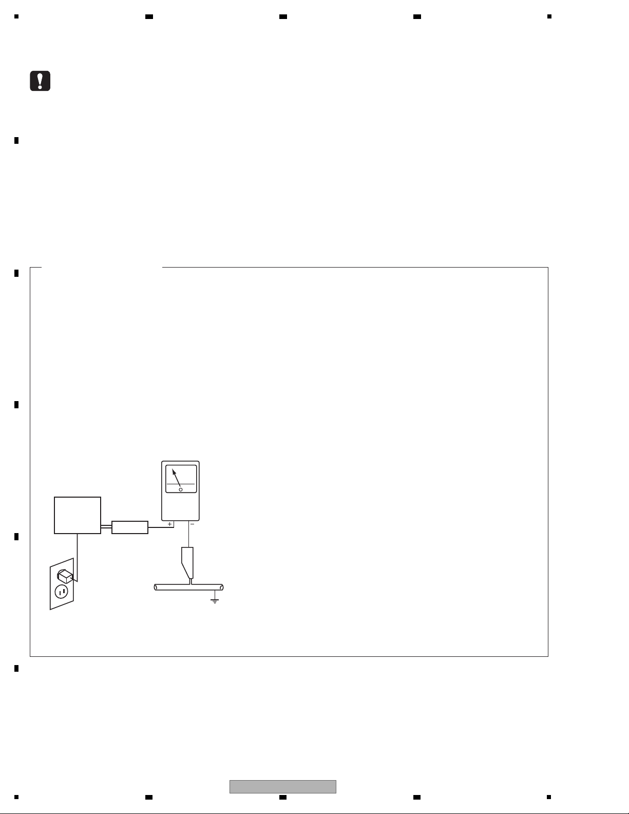
LEAKAGE CURRENT CHECK
Measure leakage current to a known earth ground
(water pipe, conduit, etc.) by connecting a leakage
current tester such as Simpson Model 229-2 or
equivalent between the earth ground and all exposed
metal parts of the appliance (input/output terminals,
screwheads, metal overlays, control shaft, etc.). Plug
the AC line cord of the appliance directly into a 120 V
AC 60 Hz outlet and turn the AC power switch on. Any
current measured must not exceed 0.5 mA.
ANY MEASUREMENTS NOT WITHIN THE LIMITS
OUTLINED ABOVE ARE INDICATIVE OF A POTENTIAL
SHOCK HAZARD AND MUST BE CORRECTED BEFORE
RETURNING THE APPLIANCE TO THE CUSTOMER.
2. PRODUCT SAFETY NOTICE
Many electrical and mechanical parts in the appliance
have special safety related characteristics. These are
often not evident from visual inspection nor the protection
afforded by them necessarily can be obtained by using
replacement components rated for voltage, wattage, etc.
Replacement parts which have these special safety
characteristics are identified in this Service Manual.
Electrical components having such features are
identified by marking with a > on the schematics and on
the parts list in this Service Manual.
The use of a substitute replacement component which
does not have the same safety characteristics as the
PIONEER recommended replacement one, shown in the
parts list in this Service Manual, may create shock, fire,
or other hazards.
Product Safety is continuously under review and new
instructions are issued from time to time. For the latest
information, always consult the current PIONEER Service
Manual. A subscription to, or additional copies of,
PIONEER Service Manual may be obtained at a nominal
charge from PIONEER.
Leakage
current
tester
Reading should
not be above
0.5 mA
Device
under
test
Test all
exposed metal
surfaces
Also test with
plug reversed
(Using AC adapter
plug as required)
Earth
ground
AC Leakage Test
(FOR USA MODEL ONLY)
2 3 4
SAFETY INFORMATION
A
B
C
D
E
F
2
1
2 3 4
DJM-250-W

5
6 7 8
CONTENTS
SAFETY INFORMATION.......................................................................................................................................................... 2
1. SERVICE PRECAUTIONS ....................................................................................................................................................4
1.1 NOTES ON SOLDERING...............................................................................................................................................4
2. SPECIFICATIONS ................................................................................................................................................................. 5
3. BASIC ITEMS FOR SERVICE .............................................................................................................................................. 6
3.1 CHECK POINTS AFTER SERVICING ........................................................................................................................... 6
3.2 JIGS LIST ....................................................................................................................................................................... 6
3.3 PCB LOCATIONS ...........................................................................................................................................................7
4. BLOCK DIAGRAM ................................................................................................................................................................8
4.1 OVERALL CONNECTION DIAGRAM............................................................................................................................. 8
4.2 OVERALL BLOCK DIAGRAM....................................................................................................................................... 10
4.3 POWER BLOCK DIAGRAM ......................................................................................................................................... 12
5. DIAGNOSIS ........................................................................................................................................................................ 14
5.1 TROUBLESHOOTING..................................................................................................................................................14
5.2 PROTECTION CIRCUIT............................................................................................................................................... 18
6. SERVICE MODE................................................................................................................................................................. 19
6.1 TEST MODE.................................................................................................................................................................19
7. DISASSEMBLY ................................................................................................................................................................... 20
8. EACH SETTING AND ADJUSTMENT................................................................................................................................25
9. EXPLODED VIEWS AND PARTS LIST............................................................................................................................... 26
9.1 PACKING SECTION .....................................................................................................................................................26
9.2 EXTERIOR SECTION .................................................................................................................................................. 28
10. SCHEMATIC DIAGRAM .................................................................................................................................................... 32
10.1 MIXER and CH FADER PCB ASSYS......................................................................................................................... 32
10.2 I/O, MASTER OUTPUT, BALANCE OUTPUT and PHONE PCB ASSYS .................................................................. 34
11. PCB CONNECTION DIAGRAM........................................................................................................................................36
11.1 MIXER and CH FADER PCB ASSYS......................................................................................................................... 36
11.2 I/O
12. PCB PARTS LIST .............................................................................................................................................................. 44
, MASTER OUTPUT, BALANCE OUTPUT and PHONE PCB ASSYS .................................................................. 40
A
B
C
D
E
F
DJM-250-W
5
6 7 8
3

1
• For environmental protection, lead-free solder is used on the printed circuit boards mounted in this unit.
Be sure to use lead-free solder and a soldering iron that can meet specifications for use with lead-free solders for repairs
accompanied by reworking of soldering.
• Compared with conventional eutectic solders, lead-free solders have higher melting points, by approximately 40 ºC.
Therefore, for lead-free soldering, the tip temperature of a soldering iron must be set to around 373 ºC in general, although
the temperature depends on the heat capacity of the PC board on which reworking is required and the weight of the tip of
the soldering iron.
Do NOT use a soldering iron whose tip temperature cannot be controlled.
Compared with eutectic solders, lead-free solders have higher bond strengths but slower wetting times and higher melting
temperatures (hard to melt/easy to harden).
The following lead-free solders are available as service parts:
• Parts numbers of lead-free solder:
GYP1006 1.0 in dia.
GYP1007 0.6 in dia.
GYP1008 0.3 in dia.
2 3 4
1. SERVICE PRECAUTIONS
1.1 NOTES ON SOLDERING
A
B
C
D
E
F
4
1
2 3 4
DJM-250-W
5
AC adapter
Power..............................................AC 100 V to 240 V, 50 Hz/60 Hz
Rated current........................................................................ 800 mA
Rated output................................................................... DC 5 V, 3 A
General – Main Unit
Main unit weight.........................................................3.1 kg (6.83 lb)
Max. dimensions........240 mm (W) × 107.7 mm (H) × 300.2 mm (D)
(9.45 in. (W) × 4.24 in. (H) × 11.8 in. (D))
Tolerable operating temperature
............................................. +5 °C to +35 °C (+41 °F to +95 °F)
Tolerable operating humidity............ 5 % to 85 % (no condensation)
Audio Section
Sampling rate ........................................................................ 48 kHz
A/D, D/A converter.................................................................. 24 bits
Frequency characteristic
CD/LINE/AUX/MIC ...............................................20 Hz to 20 kHz
S/N ratio (rated output)
CD ........................................................................................ 91 dB
LINE...................................................................................... 91 dB
PHONO ................................................................................ 86 dB
MIC....................................................................................... 80 dB
Total harmonic distortion (CD — MASTER 1) ..................... 0.007 %
Standard input level / Input impedance
CD ..........................................................................–12 dBu/10 kΩ
LINE........................................................................–12 dBu/47 kΩ
PHONO ..................................................................–48 dBu/47 kΩ
MIC.........................................................................–52 dBu/10 kΩ
AUX 1 .....................................................................–18 dBu/10 kΩ
AUX 2, 3 .................................................................–12 dBu/10 kΩ
Standard output level / Load impedance / Output impedance
MASTER 1.....................................................+6 dBu/10 kΩ/330 Ω
MASTER 2.......................................................+2 dBu/10 kΩ/1 kΩ
PHONES .......................................................... +2 dBu/32 Ω/33 Ω
Rated output level / Load impedance
MASTER 1............................................................. +22 dBu/10 kΩ
MASTER 2............................................................. +18 dBu/10 kΩ
Crosstalk (CD)..................................................................... 74 dB
Channel equalizer characteristic
HI.................................................................–∞ to + 9 dB (13 kHz)
MID................................................................ –∞ to + 9 dB (1 kHz)
LOW ...............................................................–∞ to +9 dB (70 Hz)
MIC/AUX equalizer characteristics
HI......................................................... –12 dB to +12 dB (10 kHz)
LOW .................................................... –12 dB to +12 dB (100 Hz)
Input/output terminals
CD input ter
minal
RCA pin jack......................................................................... 2 sets
PHONO/LINE input terminals
RCA pin jack......................................................................... 2 sets
MIC input terminal
Phone jack (Ø 6.3 mm)...........................................................1 set
AUX input terminal
RCA pin jack......................................................................... 2 sets
Mini phone jack (Ø 3.5 mm) ...................................................1 set
MASTER output terminal
RCA pin jacks.........................................................................1 set
BALANCED OUTPUT output terminal
XLR connector........................................................................1 set
PHONES output terminal
Stereo phone jack (Ø 6.3 mm) ...............................................1 set
CONTROL terminal
Mini phone jack (Ø 3.5 mm) .................................................2 sets
The specifications and design of this product are subject to change
without notice.
(SVYXE8: 411-DJM250-842-HA)
(FLPXE: 411-DJM250-841-HA)
(KXE5: 411-DJM250-845-HA)
(UXECB: 411-DJM250-840-HA)
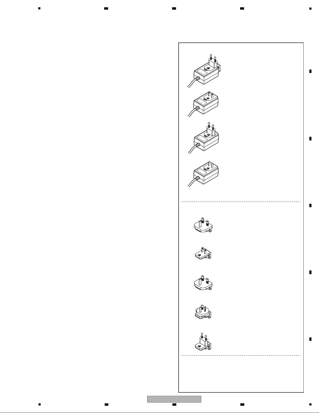
AC adapter
Power plug
Operating instructions
(SVYXE8: 502-DM250B-3136-HA)
(UXECB: 502-DM250A-3135-HA)
(FLPXE: 502-DM250F-3140-HA)
(KXE5: 502-DM250E-3139-HA)
(AXE5: 502-DM250D-3138-HA)
Accessories
(SVYXE8: 420-DJM250-362-HA)
(FLPXE: 420-DJM250-361-HA)
(FLPXE: 420-DJM250-362-HA)
(FLPXE: 420-DJM250-363-HA)
(FLPXE: 420-DJM250-364-HA)
(AXE5: 411-DJM250-844-HA)
for Mexico, Taiwan, etc.
for Hong Kong, Malaysia, Singapore, etc.
for Australia, New Zealand, etc.
for Thailand, etc.
for UK
2. SPECIFICATIONS
6 7 8
A
5
6 7 8
DJM-250-W
B
C
D
E
F
5
1
Item to be checked regarding audio
Distortion
Noise
Volume too low
Volume too high
Volume fluctuating
Sound interrupted
See the table below for the items to be checked regarding audio.
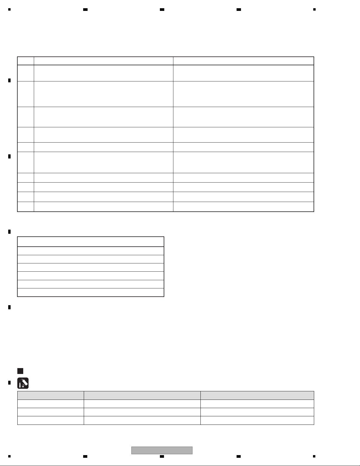
Items to be checked after servicing
To keep the product quality after servicing, confirm recommended check points shown below.
No. Procedures Check points
2 Confirm whether the customer complain has been solved.
If the customer complain occurs with the specific source, such as
Mic, each Input, Fader, Equalizer, and Trim, input that specific
source for checking.
The customer complain must not be reappeared.
Audio and operations must be normal.
1 Check the firmware version in Test mode. The firmware version must be the latest one.
If it is not the latest one, be sure to update it.
3 Check the analog audio input
(Check the Channel 1, 2, MIC and AUX.) (Make the analog
connections with CDJ player, analog player and MIC.)
Audio and operations must be normal.
4 Check the analog audio output (MASTER1 and 2.)
(Make the analog connection with CDJ player.)
Audio and operations must be normal.
5 Check the headphones output. There must be no errors, such as noise, in the audio output.
6 Check playback, using the fader function.
(Select the fader function then check operations of each channel
with audio signals.)
There must be no errors in audio output and operations of each
channel.
8 Check the LEDs. Check that all the LEDs light in Test mode.
7 Check the buttons. Make sure that all buttons on the main unit function properly.
9 Check the user settings. They must be returned to those set before repair.
10 Check the appearance of the product.
No scratches or dirt on its appearance after receiving it for service.
Lubricants and Glues List
Name Part No. Remarks
Adhesive GYL1001 (ThreeBond: 1401B) Refer to "7. DISASSEMBLY".
Adhesive ——
(Sony Chemical&Information Devic: SC608Z2)
Refer to "7. DISASSEMBLY".
Adhesive GYL1005 (CEMEDINE: 575) Refer to "7. DISASSEMBLY".
2 3 4
3. BASIC ITEMS FOR SERVICE
3.1 CHECK POINTS AFTER SERVICING
A
B
C
D
E
3.2 JIGS LIST
F
6
1
2 3 4
DJM-250-W
5
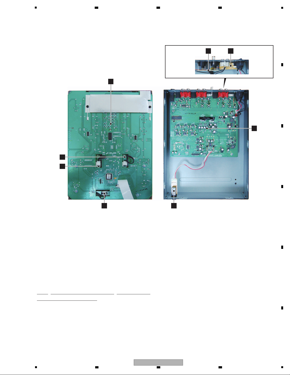
C
I/O PCB
ASSY
D
MASTER OUTPUT
PCB ASSY
A
MIXER PCB ASSY
• Bottom view
E
BALANCE OUTPUT
PCB ASSY
F
PHONE PCB ASSY
B
CH FADER PCB ASSY
B
CH FADER
PCB ASSY
B
CH FADER
PCB ASSY
1..MIXER PCB ASSY 704-DJM250-A026-HA
1..CH FADER PCB ASSY 704-DJM250-A032-HA
1..I/O PCB ASSY 704-DJM250-A028-HA
1..MASTER OUTPUT PCB ASSY 704-DJM250-A031-HA
1..BALANCE OUTPUT PCB ASSY 704-DJM250-A029-HA
1..PHONE PCB ASSY 704-DJM250-A030-HA
Mark No. Description Part No.
LIST OF ASSEMBLIES
NOTES: - Parts marked by “NSP” are generally unavailable because they are not in our Master Spare Parts List.
-
The > mark found on some component parts indicates the importance of the safety factor of the part.
Therefore, when replacing, be sure to use parts of identical designation.
3.3 PCB LOCATIONS
6 7 8
A
B
C
D
E
F
DJM-250-W
5
6 7 8
7
1
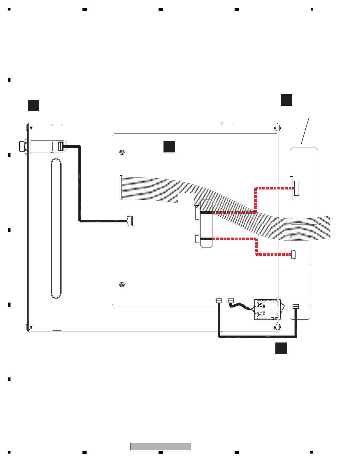
CN204
1. L+
2. XLRG
3. L-
4. R+
5. XLRG
6. R-
1. LCH
2. GND
3. RCH
1. LCH
2. GND
3. RCH
4. R
3. GND
2. GND
1. L
4. R
3. GND
2. GND
1. L
4P 2.5 CONNECTOR WIRE
(404-AMW4-2730-HA)
CN1A
W204
W201
CN201
CN203
CN202
CN200
W203
W202
C
I/O PCB ASSY
(704-DJM250-A028-HA)
F
PHONE PCB ASSY
(704-DJM250-A030-HA)
D
MASTER OUT
(704-DJM250
E
BALANCE O
(704-DJM2
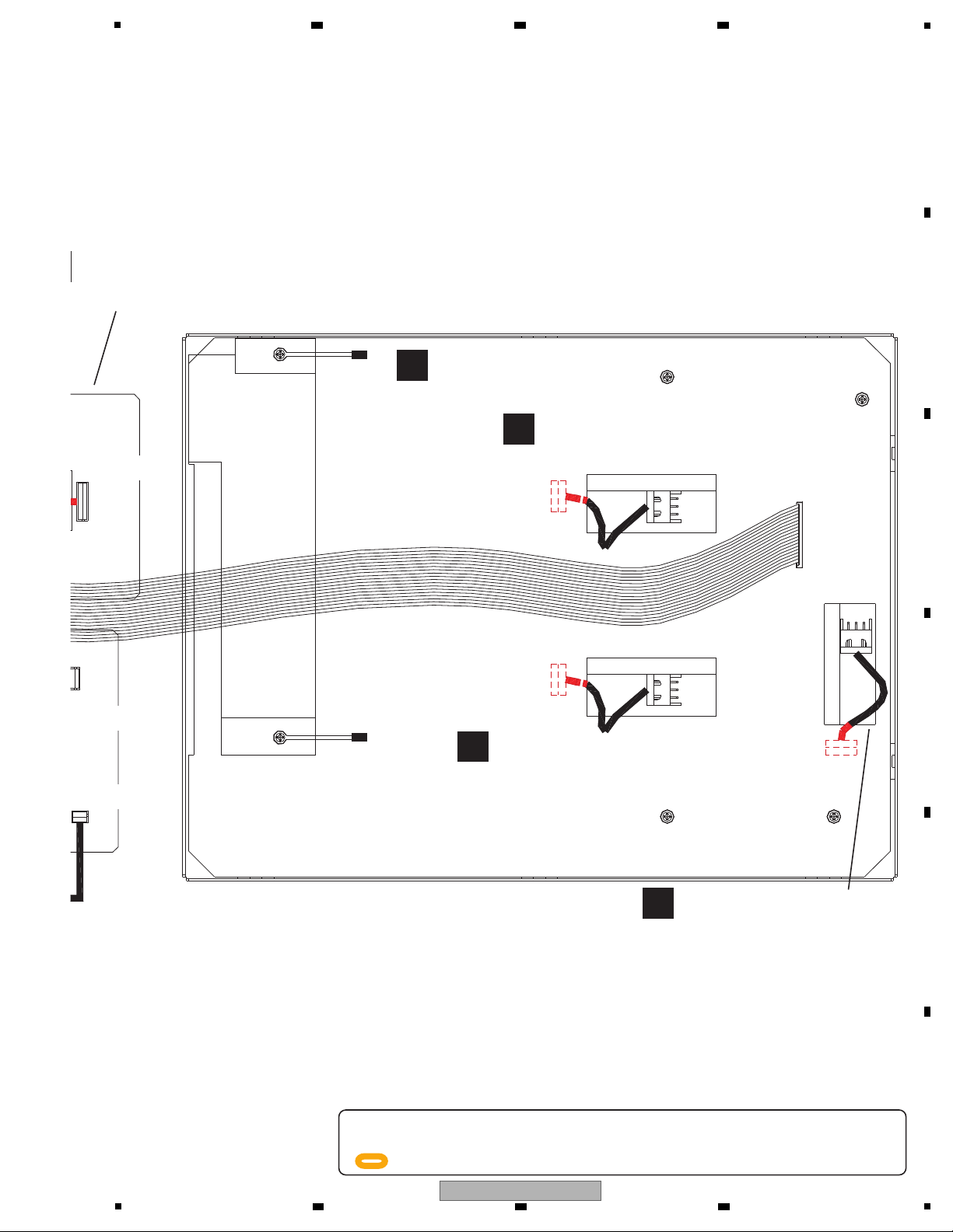
1. L+
2. XLRG
3. L-
4. R+
5. XLRG
6. R-
20. GND
19. SELB
18. SELA
17. PC2B
16. PC2A
15. PC1B
14. PC1A
13. MUTE-M
12. CL
11. DI
10. CE
9. DRST
8. MOSI
7. MISO
6. HREQ
5. SS
4. GND
3. SCK SCL
2. GND
1. D5V
2P 2.0/2.5 CONNECTOR WIR
(404-DJM250-3623-HA)
3P 2.0 CONNECTOR WIRE
(404-DJM250-3622-HA)
6P 2.0 CONNECTOR WIRE
(404-ID-3048-HA)
2 3 4
4. BLOCK DIAGRAM
4.1 OVERALL CONNECTION DIAGRAM
A
B
C
D
E
F
8
1
2 3 4
DJM-250-W
5
CN01
CN01
CN01
W3
1. AD5V
2. AD13
3. GND
3P 2.0 CONNECTOR WIRE
(404-DJM250-3624-HA)
3P 2.0 CONNECTOR WIRE
(404-DJM250-3624-HA)
3P 2.0 CONNECTOR WIRE
(404-DJM250-3624-HA)
1. L+
2. XLRG
3. L-
4. R+
5. XLRG
6. R-
1. AD5V
2. AD13
3. GND
1. LCH
2. GND
3. RCH
1. AD5V
2. AD13
3. GND
1. AD5V
2. AD13
3. GND
1. AD5V
2. AD13
3. GND
1. AD5V
2. AD13
3. GND
W4
W5
CN1B
20P 1.0 FFC CABLE
(406-DJM250-1190-HA)
W203
W202
A
MIXER PCB ASSY
(704-DJM250-A026-HA)
B
CH FADER PCB ASSY
(704-DJM250-A032-HA)
B
CH FADER PCB ASSY
(704-DJM250-A032-HA)
B
CH FADER PCB ASSY
(704-DJM250-A032-HA)
BALANCE OUTPUT PCB ASSY
(704-DJM250-A029-HA)
20. GND
19. SELB
18. SELA
17. PC2B
16. PC2A
15. PC1B
14. PC1A
13. MUTE-M
12. CL
11. DI
10. CE
9. DRST
8. MOSI
7. MISO
6. HREQ
5. SS
4. GND
3. SCK SCL
2. GND
1. D5V
404-DJM250-3623-HA)
3P 2.0 CONNECTOR WIRE
(404-DJM250-3622-HA)
6P 2.0 CONNECTOR WIRE
(404-ID-3048-HA)
-
When ordering service parts, be sure to refer to "EXPLODED VIEWS and PARTS LIST" or "PCB PARTS LIST".
-
The > mark found on some component parts indicates the impor tance of the safety factor of the part.
Therefore, when replacing, be sure to use parts of identical designation.
-
: The power supply is shown with the marked box.
6 7 8
A
B
C
D
E
F
5
6 7 8
DJM-250-W
9
1
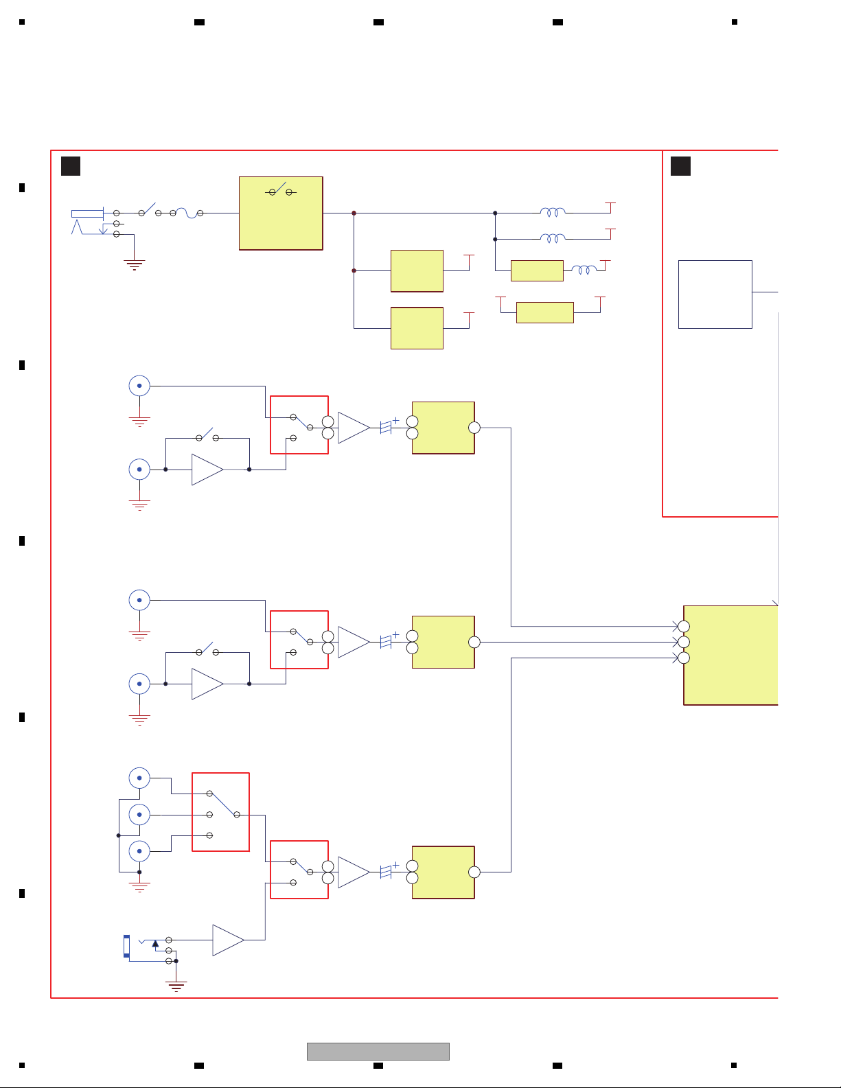
ADC
PCM1803
ADC
PCM1803
DSP5
DI0
DI1
(48K/24bit/512fs for A/D
(I2S format for audio
(24.57
CH FADER * 2
CS FADER * 1
MIC
Balance(mono)
ADC
PCM1803
+40dB
DI2
D3.3V
1
2
3
JK1
DC 5V/3A
BA03 3FP
D5V
A5V
D3.3V
BD12AK5FB
1.20V
MIC/AUX1~3
LN/PH/CD-2
LN/PH/CD-1
L
3
G
1
S
4
1
2
TPS54232
IC2
IC
IC3
IC1
IC12
IC7
IC8
IC9
IC6
IC6
IC6
IC5
INVERTER
-15V
NJM2374
BOOST
15V
AXU1
-9.32dB
AXU2
AUX3
2
1
3
LC78213
-9.32dB
-9.32dB
Line1/Phono1
CD1
2
1
3
+36dB(RIAA)
Line2/Phono2
CD2
2
1
3
LC78213
LC78213
F1
2.5 A/63 V
OVP limit 5.5V
Over Voltage
Protection
1
2
1 2
0dB
+36dB(RIAA)
1 2
C1
1
2
3
74HC4052
C
I/O PCB ASSY
A
MIXER PCB A
3
1
2
12
1
2
12
58
57
79
28
6
25
1
2
12
9
22
2 3 4
4.2 OVERALL BLOCK DIAGRAM
A
B
C
D
E
F
10
DJM-250-W
1
2 3 4
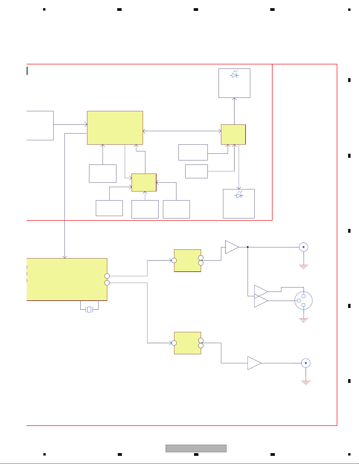
LPF&.
MASTER OUT(RCA)
LPF&.
NJM4580
NJM4556
DSP56374
STM8S207MB
MCU
TACT SW
4
EXP. AD
HC4052 * 2
ROTARY
SER.-->PAL.
PT6964
21LEDs
DO0
DO1
(I2S format for audio data)
(24.576 MHz)
24.576 M
(16 MHz )
SLIDE SW * 2
AD * 3
Master
HeadPhone
Headphone(32 ohm/6.3mm)
DAC
PCM1754
DAC
PCM1754
scan
SPI
SLIDE SW * 1
3 SEGMENT
2 SEGMENT
8 LEDs
LEVEL METER
CH1,CH2
I/O EXPAND
IC4
IC11
IC13
IC14
IC3
IC1, IC2
FIR1,FIR2
ROTARY * 1
5 SEGMENT
ROTARY
AD * 2
FIR-R/L
VR * 2
VR * 14
AD * 4
+17.6dB
+7.5dB
BALANCE
+4.4dB
NJM4580
2
3
1
MASTER OUT(XLR)
MIXER PCB ASSY
55
2
7
8
7
8
2
56
5
6 7 8
A
B
C
D
E
F
DJM-250-W
5
6 7 8
11
1
1
2
3
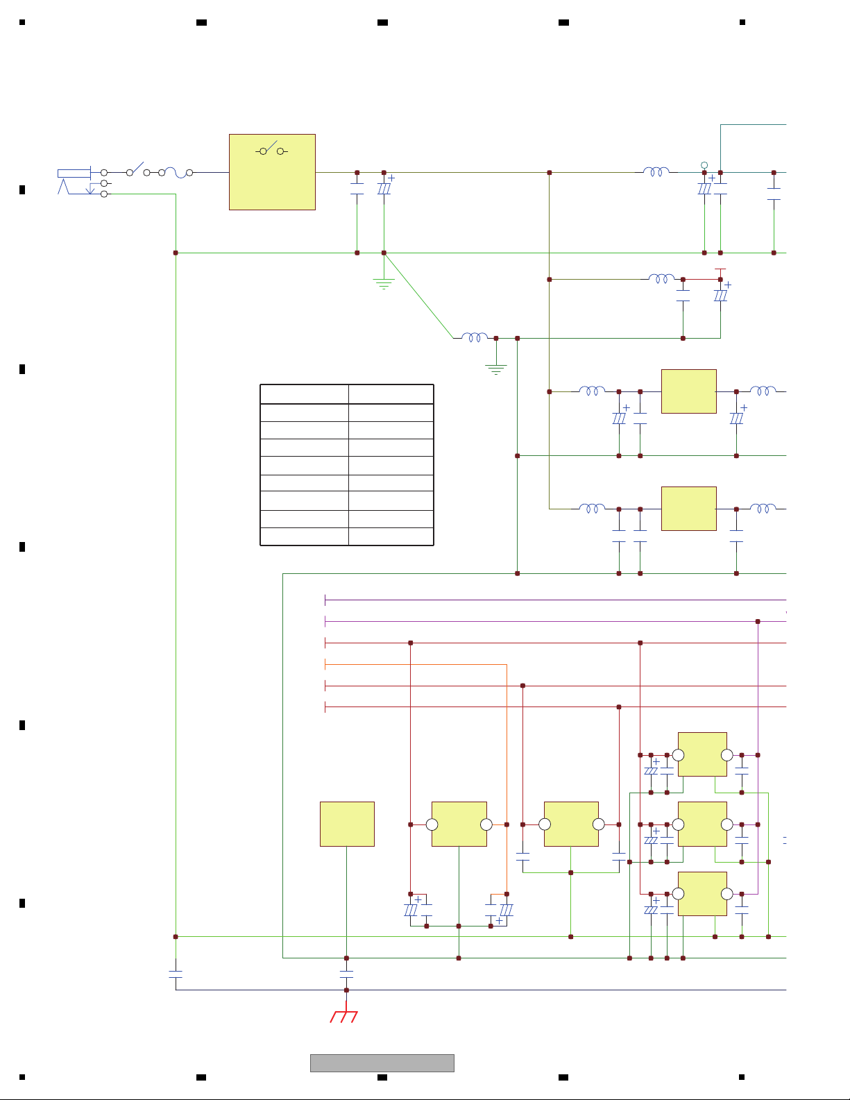
JK1
DC 5V/3A
1 2
5V->15V
BOOST
F1
2.5A/63V
OVP(5.5V)
Over Voltage
Protection
1 2
C10
330/16
D
C4
0.1
L4
Bead
A
D5V
C11
100/16
C5
0.1
L2
Bead
L5
Bead
A5V
C13
100/16
C7
0.1
C2
0.
C12
100/16
C8
0.1
L6
Bead
C25
220/25
L8
Bead
5V-> -15V
INVERTER
C2
0.
C6
0.1
L3
Bead
L7
Bead
C14
4.7/25
C18
10/25
IC3
IC2
IC5
IC6
IC7
IC8
IC9
C1
0.1
CH1 A/D
CH2 A/D
MIC/AUX
INPUT
A/D
JACK
0.01
CHASSIS
AUX
SELECT
CHANNEL
SELECT
74HC4052 LC78213
D3.3V
A5V
-5V
15V
-15V
1.2V
0.01
PCM1803A
C77
0.1
C76
0.1
C75
47/16
C74
47/16
C98
0.1
C99
0.1
C108
0.1
C123
0.1
C138
0.1
C115
100/10
C107
0.1
C128
100/10
C122
0.1
C143
100/10
C137
0.1
D3.3V
-5V
A5V
15V
-15V
Signal name Voltage (V)
D5V 5
A5V 5
D3.3V 3.3
1.2V 1.2
15V 15
-15V -15
-5V -5
AD5V 5
5
5
5
14
14
1219
16 7
14
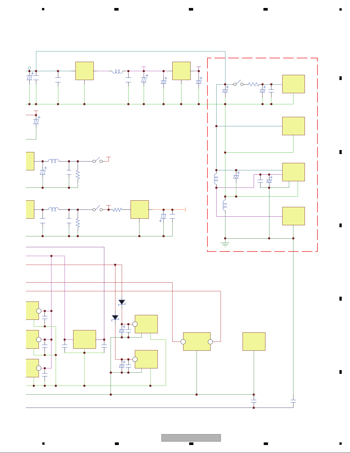
4.3 POWER BLOCK DIAGRAM
A
B
2 3 4
C
D
E
F
12
DJM-250-W
1
2 3 4
5
15V
D5V
C5
0.1
A5V
C13
100/16
C22
0.1
R5
15K,1/4W
C25
220/25
L8
Bead
1 2
-15V
C21
0.1
R4
15K,1/4W
L7
Bead
1 2
C18
10/25
-5V
C27
47/16
C9
0.1
I
G
O
IC4
C7
IC8
IC9
79L05
R13
10ohm/1W
C2
0.1
C3
470/16
C1
0.1
D3.3V
L1
BEAD
I
G
O
IC1
IC1, 2
IC4
IC13
IC11
IC14
IC207, 208, 209
BA033FP
C165
100u/10
C164
100u/10
I
COM
O
IC12
BD12KA5FP
1.2V
SCAN
LED/KEY
MCU
FADER
VR
C30
0.1
C35
100/10
C46
100/10
1 2
R8
22
C38
100u/10
L2
10uH
L1
BEAD/600ohm
C33
0.1
C36
100u/10
AD
AD5V
AD5V
ADGND
ADGND
EXPANSION
74HC4052
D/A
H.P
DSP
LPF&
MASTER
D/A
JACK
OUTPUT
0.01 0.01
DSP56374
PCM1754
C108
0.1
C123
0.1
C138
0.1
37
0.1
0.1
C172
330/10
C170
0.1
D10
1N5819
D9
1N5819
C200
330/10
C198
0.1
1.2V
D3.3V
1.2V
A5V
15V
-15V
14
14
6
6
8 4
14
6 7 8
A
B
C
D
E
F
DJM-250-W
5
6 7 8
13

1
1 Power failure
Symptom: The Master and Channel level indicator LEDs does not flash and SOUND COLOR FILTER indicatorLED
does not light.
Status of the product: A power device or power circuit failure
Diagnostic procedure:
1. Unplug the AC power cord.
2. Measure if terminals of capacitor C10, C213 and C242 is short.
3. Measure if AC adapter is DC 5 V input.
4. Plug in the AC power cord, check the positive voltage of C10:
A. If it is not, check if Q28, Q29 and IC15 is failure.
B. If it is 5 V, check each DC voltage, measure C11 positive to ground is +5 V
C13 positive to ground is +5 V, C3 positive to ground is +3.3 V, C27 negative to ground is -5 V
C222 positive to ground is +15 V, C223 negative to ground is -15 V
2 Audio is not output
Symptom: Audio is not output
Diagnostic procedure:
1. Is a signal input to the ADC?
IC7: CH1, IC8: AUX and MIC, IC9: CH2 → Pin 1 and Pin 2
A. If it is not, something is wrong with the analog -circuit block. Check if IC6 audio switch is normal.
Check if OPA (IC200, IC204: CH1, IC203, IC206: CH2, IC201, IC211, IC205: AUX and MIC) is working normally.
B. If it is, something is wrong with the digital -circuit block.
Check if there is CLOCK signal for IC7, IC8, IC9 → Pin 10, Pin 11, Pin 12 and Pin 15
2. Is a signal output from the ADC?
IC13: MASTER, IC14: HP → Pin 7 and Pin 8
A. If it is, something is wrong with the analog -circuit block.
Check if output amplifier (IC207, IC208: MASTER, IC209: HP) is working normally.
Check if each MUTE transistor (Q12 to Q16 and Q30 to Q31: MASTER, Q18 to Q21: HP) Base Pin is -15 V.
B. If it is not, something is wrong with the digital -circuit block.
Check if there is CLOCK signal for IC13, IC14 → Pin 1, Pin 2, Pin 3 and Pin 16
3 CD, PHONO/LINE input selector switch on the front panel can not be switched
Symptom: The CD and PHONO/LINE inputs cannot be switched.
Diagnostic procedure:
1. While CD and PHONO/LINE input is normal, the SW1: CH1, SW2: CH2 or audio switch IC6 may be in failure.
4 PHONO/LINE selector switch can not be switched
Symptom: The PHONO/LINE inputs cannot be switched.
Diagnostic procedure:
1. While PHONO/LINE input is normal, the SW200: CH1, SW201: CH2 or Q6, Q7: CH1, Q8, Q9: CH2 may be in failure.
5 MIC, OFF, AUX 1, AUX 2, AUX 3 input selector switch can not be switched
Symptom: The MIC, OFF, AUX 1, AUX 2, AUX 3 inputs cannot be switched.
Diagnostic procedure:
1. While MIC and AUX input is normal, the section switch SW7 or audio switch IC5 and IC6 may be in failure.
2 3 4
5. DIAGNOSIS
5.1 TROUBLESHOOTING
A
B
C
D
E
F
14
DJM-250-W
1
2 3 4
 Loading...