

Pioneer DEH-X2900UI SERVICE MANUAL

PIONEER CORPORATION 28-8, Honkomagome 2-chome, Bunkyo-ku, Tokyo 113-0021, Japan
PIONEER ELECTRONICS (USA) INC. P.O. Box 1760, Long Beach, CA 90801-1760, U.S.A.
PIONEER EUROPE NV Haven 1087, Keetberglaan 1, 9120 Melsele, Belgium
PIONEER ELECTRONICS ASIACENTRE PTE. LTD. 2 Jalan Kilang Barat, #07-01, Singapore 159346
PIONEER CORPORATION 2016
CD RDS RECEIVER
ORDER NO.
CRT5941
DEH-X2900UI/XNUC
DEH-X2900UI
DEH-X1
DEH-X1
DEH-X2900UI
DEH-X2950UI
DEH-X2990UI
This service manual should be used together with the following manual(s):
Model No. Order No. Mech. Module Remarks
/XNCS
/XNME
/XNEW5
/XNGS
/XNID
/XNUC
CX-3287 CRT4759 S11.6STD CD Mech. Module : Circuit Descriptions, Mech. Descriptions, Disassembly
K-ZZZ AUG. 2016 Printed in Japan
1234
1234
C
D
F
A
B
E
SAFETY INFORMATION
CAUTION
Where in a manufacturer’s service documentation, for example in circuit diagrams or lists
of components, a symbol is used to indicate that a specific component shall be replaced only
by the component specified in that documentation for safety reasons, the following symbol shall
be used:
This service manual is intended for qualified service technicians; it is not meant for the casual do-it-yourselfer.
Qualified technicians have the necessary test equipment and tools, and have been trained to properly and safely repair
complex products such as those covered by this manual.
Improperly performed repairs can adversely affect the safety and reliability of the product and may void the warranty.
If you are not qualified to perform the repair of this product properly and safely, you should not risk trying to do so
and refer the repair to a qualified service technician.
CAUTION:
USE OF CONTROLS OR ADJUSTMENTS OR PERFORMANCE OF PROCEDURES OTHER THAN THOSE
SPECIFIED HEREIN MAY RESULT IN HAZARDOUS RADIATION EXPOSURE.
- Safety Precautions for those who Service this Unit.
When checking or adjusting the emitting power of the laser diode exercise caution in order to get safe, reliable
results.
Caution:
1. During repair or tests, minimum distance of 13 cm from the focus lens must be kept.
2. During repair or tests, do not view laser beam for 10 seconds or longer.
WARNING!
The AEL (accessible emission level )of the laser power output is less than CLASS 1
but the laser component is capable of emitting radiation exceeding the limit for
CLASS 1.
A specially instructed person should do servicing operation of the apparatus.
CAUTION
This product is a class 1 laser product classified under the Safety of laser products, IEC
60825-1:2007.
Laser diode characteristics
Wave length : 785 nm to 814 nm
Maximum output : 1 190 µW(Emitting period : unlimited)
Additional Laser Caution
Transistors Q101 in PCB drive the laser diodes.
When Q101 is shorted between their terminals, the laser diodes will radiate beam.
If the top cover is removed with no disc loaded while such short-circuit is continued,
the naked eyes may be exposed to the laser beam.
CAUTION
Danger of explosion if battery is incorrectly replaced.
Replaced only with the same or equivalent type recommended by the manufacturer.
Discard used batteries according to the manufacturer's instructions.
2
DEH-X2900UI/XNUC

5678
56
7
8
C
D
F
A
B
E
CONTENTS
SAFETY INFORMATION .....................................................................................................................................2
1. SERVICE PRECAUTIONS ................................................................................................................................4
1.1 SAFETY PRECAUTIONS...........................................................................................................................4
1.2 NOTES ON DISASSEMBLY / ASSEMBLY .................................................................................................4
1.3 NOTES ON REPLACING PARTS ...............................................................................................................5
1.4 NOTES ON ADJUSTMENT........................................................................................................................6
1.5 OTHERS.....................................................................................................................................................6
2. SPECIFICATIONS.............................................................................................................................................6
2.1 SPECIFICATIONS ......................................................................................................................................6
2.2 DISC/CONTENT FORMAT .........................................................................................................................6
3. BASIC ITEMS FOR SERVICE ..........................................................................................................................7
3.1 CHECK POINTS AFTER SERVICING .......................................................................................................7
3.2 PCB LOCATIONS .......................................................................................................................................7
3.3 JIGS LIST ...................................................................................................................................................8
3.4 CLEANING .................................................................................................................................................8
4. BLOCK DIAGRAM ............................................................................................................................................9
4.1 BLOCK DIAGRAM......................................................................................................................................9
4.2 POWER SUPPLY SYSTEM FIGURE .......................................................................................................10
5. DIAGNOSIS ....................................................................................................................................................11
5.1 OPERATIONAL FLOWCHART.................................................................................................................11
5.2 ERROR CODE LIST.................................................................................................................................12
5.3 CONNECTOR FUNCTION DESCRIPTION .............................................................................................15
5.4 FUSE CHECK...........................................................................................................................................16
6. SERVICE MODE.............................................................................................................................................17
6.1 DISPLAY TEST MODE1 ...........................................................................................................................17
6.2 DISPLAY TEST MODE2 ...........................................................................................................................18
6.3 SOFTWARE VERSION UP METHOD......................................................................................................19
6.4 CD TEST MODE.......................................................................................................................................20
7. DISASSE
MBLY ...............................................................................................................................................21
8. EACH SETTING AND ADJUSTMENT............................................................................................................27
8.1 ADJUSTMENT REQUIRED WHEN THE UNIT IS REPLACED ...............................................................27
8.2 CD ADJUSTMENT ...................................................................................................................................27
8.3 CHECKING THE GRATING AFTER CHANGING THE PICKUP UNIT ....................................................28
9. EXPLODED VIEWS AND PARTS LIST ..........................................................................................................30
9.1 PACKING ..................................................................................................................................................30
9.2 EXTERIOR ...............................................................................................................................................32
9.3 CD MECHANISM MODULE .....................................................................................................................34
10. SCHEMATIC DIAGRAM................................................................................................................................36
10.1 TUNER AMP UNIT(VEHICLE I/F) ..........................................................................................................36
10.2 TUNER AMP UNIT(SYSTEM REGULATOR) .........................................................................................37
10.3 TUNER AMP UNIT(BT) ..........................................................................................................................38
10.4 TUNER AMP UNIT(OTHER SUPPLY)....................................................................................................39
10.5 TUNER AMP UNIT(SYSTEM u-COM) ...................................................................................................40
10.6 TUNER AMP UNIT(iPod I/F)...................................................................................................................41
10.7 TUNER AMP UNIT(E-VOL)....................................................................................................................42
10.8 KEYBOARD UNIT(LITHIO) ....................................................................................................................43
10.9 TUNER AMP UNIT(S11.6 I/F) ................................................................................................................44
10.10 TUNER AMP UNIT(EXTERNAL I/F).....................................................................................................45
10.11 TUNER AMP UNIT(POWER AMP) ......................................................................................................46
10.12 KEYBOARD UNIT(1/3).........................................................................................................................47
10.13 CD CORE UNIT(S11.6VA) ...................................................................................................................48
10.14 CD CORE UNIT(S11.6 STD)................................................................................................................49
10.15 WAVEFORMS.......................................................................................................................................50
11. PCB CONNECTION DIAGRAM....................................................................................................................52
11.1 TUNER AMP UNIT .................................................................................................................................52
11.2 KEYBOARD UNIT ..................................................................................................................................54
11.3 CD CORE UNIT(S11.6VA) .....................................................................................................................55
11.4 CD CORE UNIT(S11.6STD)...................................................................................................................57
12. ELECTRICAL PARTS LIST ...........................................................................................................................59
DEH-X2900UI/XNUC
3
1234
1234
C
D
F
A
B
E
1. SERVICE PRECAUTIONS
You should conform to the regulations governing the product (safety, radio and noise, and other regulations), and
should keep the safety during servicing by following the safety instructions described in this manual.
Please keep the distance of more than 13 cm from focus lens for safety when you check pickup and make adjustment,
and do not look straight at Laser Beam for more than 10 seconds.
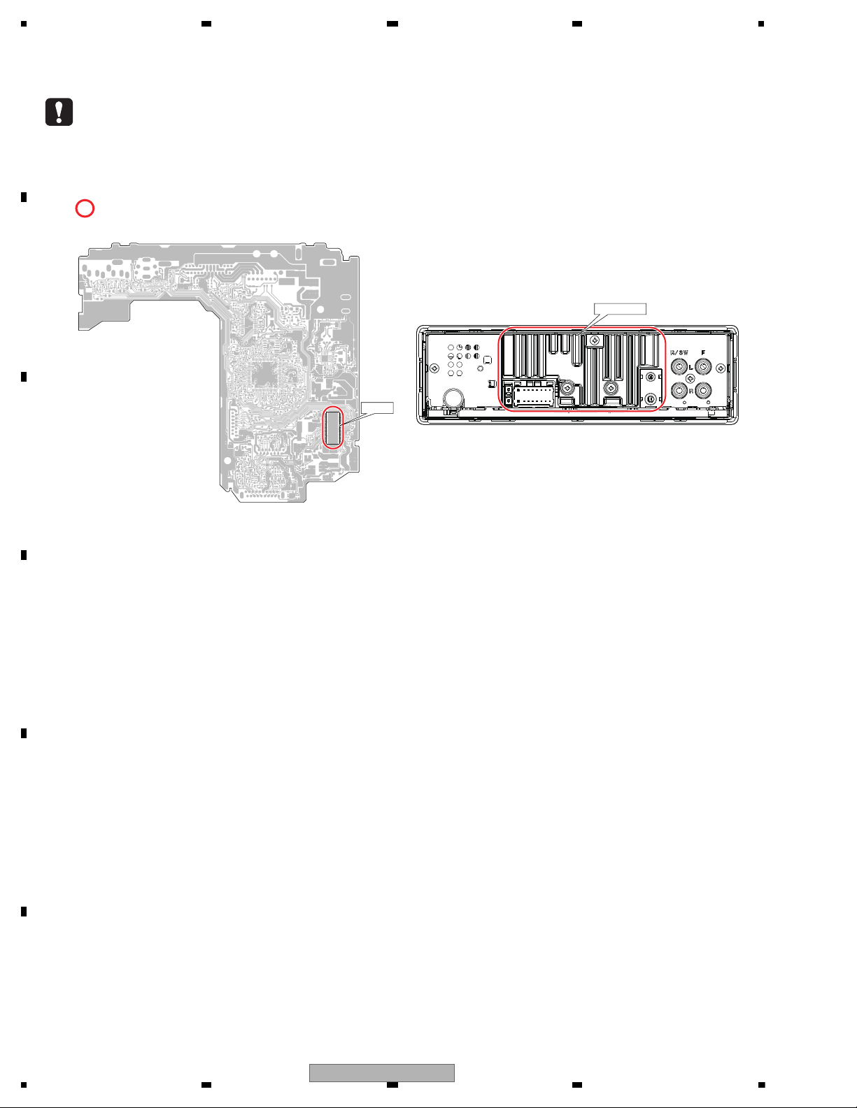
area and a heat sink becomes hot areas. Be careful not to burn yourself.
TUNER AMP UNIT (Side A)
IC151
HEAT SINK
Before disassembling the unit, be sure to turn off the power. Unplugging and plugging the connectors during power-on
mode may damage the ICs inside the unit.
To protect the pickup unit from electrostatic discharge during servicing, take an appropriate treatment (shorting-solder)
by referring to CRT4759 "3.4 HOW TO REMOVE AND INSTALL THE CD CORE UNIT".
Please be sure to conduct line process to original status if you make assembling after repair.
1.1 SAFETY PRECAUTIONS
1.2 NOTES ON DISASSEMBLY / ASSEMBLY
4
DEH-X2900UI/XNUC

5678
56
7
8
C
D
F
A
B
E
Be careful in handling ICs. Some ICs such as MOS type are so fragile that they can be damaged by electrostatic
induction.
Please be careful of not to apply static charge onto integrated circuits, etc, when you conduct repair work.
Especially, please use soldering iron with its tip grounded.
Also, please use a pair of tweezers with static charge protection capability if there is the possibility of contacting to
device terminals, and avoid the use of metal-made tweezers.
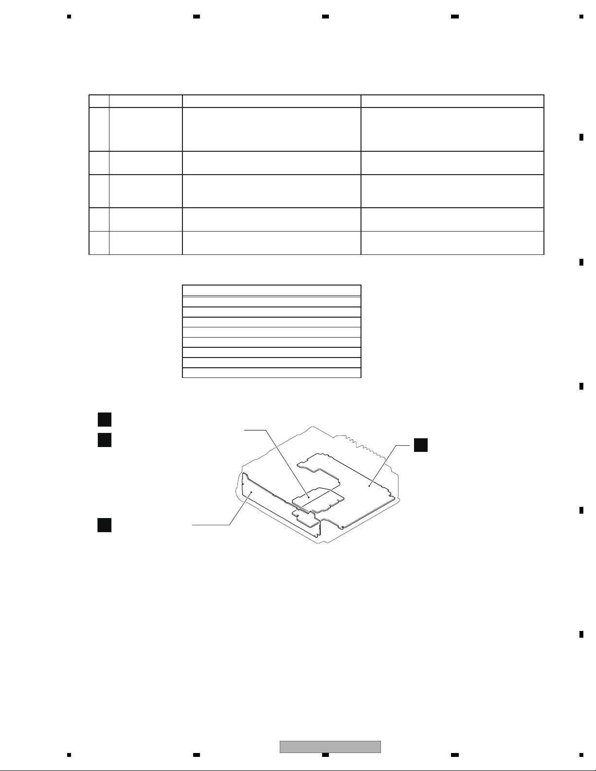
The part listed below is difficult to replace as a discrete component part.
When the part listed in the table is defective, replace whole Assy.
There are 2 kinds of CD Mechanism Module as follows for each models on this Service Manual.
These modules are interchangeable in case of replacing whole module but configuration parts such as Pickup Unit,
CD Core Unit and other component parts might not be interchangeable each other.
When replacing these configuration parts, please refer to following "How to distinguish the type of CD Mechanism
Module" and "12. ELECTRICAL PARTS LIST" for each module and adopt correct ones.
In case either of configuration part is unavailable, replace whole CD Mechanism Module.
Regarding applicable CD Mechanism Module for each models, please refer to (2) CONTRAST TABLE in "9.2
EXTERIOR" of "9. EXPLODED VIEWS AND PARTS LIST".
Heat pad
IC151 BD49101AEFSSYSTEM POWER SUPPLY
SYMBOL/DESCRIPTION PART NUMBER
CD Mechanism Module(S11.6) CXK5807
CD Mechanism Module(S11.6) CXK5808
<How to distinguish the type of CD Mechanism Module>
CXK5807
IC201 = PE5791*
connector = black
Mech no. = 5807*
Mech no. = 5808*
connector = white
IC201 = PEQ094*
CXK5808
1.3 NOTES ON REPLACING PARTS
DEH-X2900UI/XNUC
5

1234
1234
C
D
F
A
B
E
1.4 NOTES ON ADJUSTMENT
Some of the adjustment is required when the part is replaced.
Pease refer to “8. EACH SETTING AND ADJUSTMENT”.
For environmental protection, lead-free solder is used on the printed circuit boards mounted in this unit.
Be sure to use lead-free solder and a soldering iron that can meet specifications for use with lead-free solders for
repairs accompanied by reworking of soldering.
To secure the front panel
The front panel can be secured with the supplied screw.
Notes on soldring
Screw
BPZ20P060FTC (UC)
XXX7020 (Except UC)
For all items except the backup current, refer to the Owner's Manual.
Backup current......................... 4.0 mA or less
1.5 OTHERS
2. SPECIFICATIONS
2.1 SPECIFICATIONS
2.2 DISC/CONTENT FORMAT
6
DEH-X2900UI/XNUC
5678
56
7
8
C
D
F
A
B
E
demrifnocebotmetIserudecorP.oN
1 Confirm whether the customer complain has
been solved.
If the customer complain occurs with the
specific media, use it for the operation check.
The customer complain must not be
reappeared.
Display, audio and operations must be
normal.
2 CD Play back a CD.
(Track search)
No malfunction on display, audio and
operation.
3 FM/AM tuner Check FM/AM tuner action.
(Seek, Preset)
Switch band to check both FM and AM.
Display, audio and operations must be
normal.
4 Check whether no disc is inside the product. The media used for the operating check must
be ejected.
retfaecnaraeppastinotridrosehctarcsoNkcehcecnaraeppA5
receiving it for service.
Item to be checked regarding audio
A:DEH-X2900UI/XNUC
B:DEH-X1/XNCS
C:DEH-X1/XNME
D:DEH-X2900UI/XNEW5
E:DEH-X2950UI/XNGS
F:DEH-X2990UI/XNID
Unit Name : Tuner Amp Unit
Unit Number : QWM4328(A)
Unit Number : QWM4330(B)
Unit Number : QWM4398(C)
Unit Number : QWM4327(D)
Unit Number : QWM4329(E)
Unit Number : QWM4331(F)
Unit Name : Keyboard Unit
Unit Number : QWM4370
Unit Name : CD Core Unit(S11.6VA)
Unit Number : CWX4269
Unit Name : CD Core Unit(S11.6STD)
Unit Number : CWX4023
Notes:
For CD Core Unit, please refer to "1.3 NOTES ON
REPLACING PARTS" for part distinguish.
A
B
Keyboard Unit
C
CD Core Unit (S11.6VA)
D
CD Core Unit (S11.6STD)
Tuner Amp Unit
3. BASIC ITEMS FOR SERVICE
3.1 CHECK POINTS AFTER SERVICING
To keep the product quality after servicing, please confirm following check points.
See the table below for the items to be checked regarding audio:
Distortion
Noise
Volume too low
Volume too high
Volume fluctuating
Sound interrupted
3.2 PCB LOCATIONS
DEH-X2900UI/XNUC
7
1234
1234
C
D
F
A
B
E
3.3 JIGS LIST
- Jigs List
- Grease List
Name
Grease
Grease
Grease No.
GEM1024
GEM1043
Remarks
CD Mechanism Module
CD Mechanism Module
e
.
ks
Name
16P FFC
Test Disc
L.P.F.
Jig No.
GGD1310
TCD-782
Remarks
Tuner Amp Unit - CD Core Unit
Checking the grating
Checking the grating (Two pieces)
Before shipping out the product, be sure to clean the
following portions by using the prescribed cleaning
tools:
Portions to be cleaned Cleaning tools
CD pickup lenses Cleaning liquid : GEM1004
Cleaning paper : GED-008
Nam
3.4 CLEANING
Grease No
emar
8
DEH-X2900UI/XNUC
5678
56
7
8
C
D
F
A
B
E
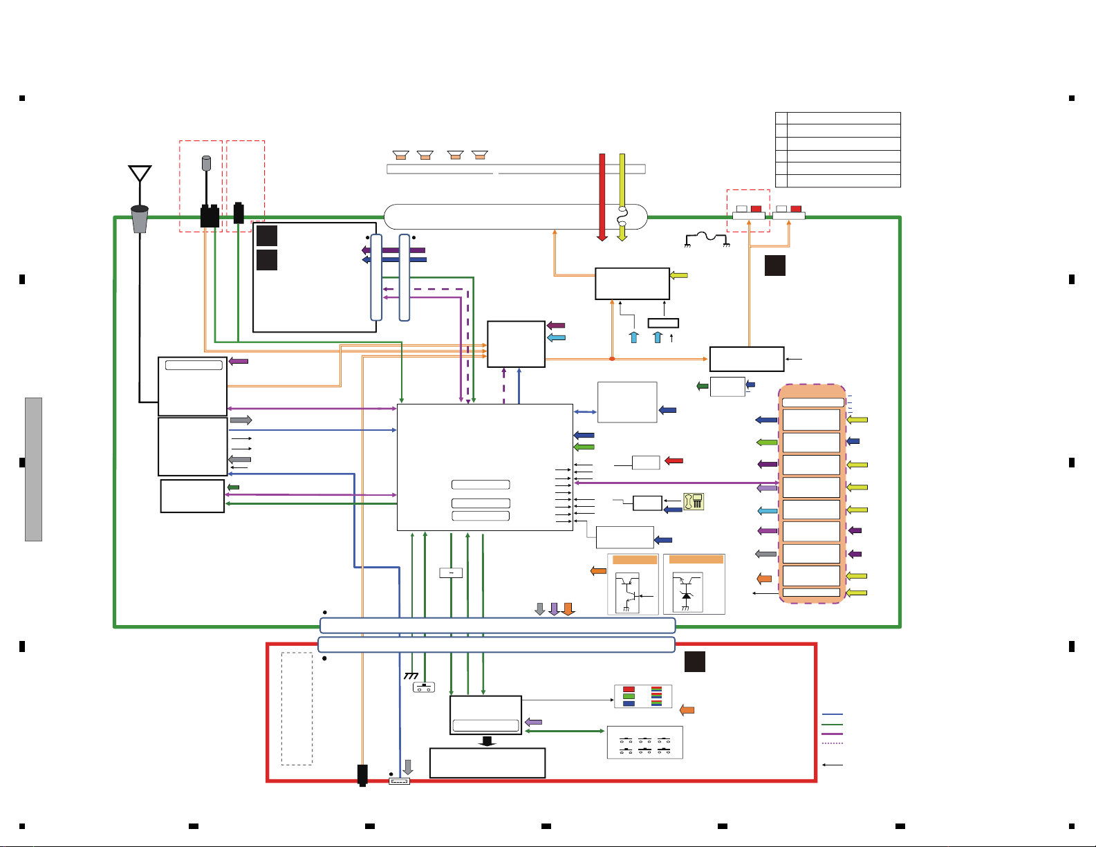
4. BLOCK DIAGRAM
4. BLOCK DIAGRAM
SYS+B 5.75
Memory: 64Kbyte
ASEN S
BSENS
BTPW VDSENS
SYNC
USBCTL
ECO TEL .IN
EN
MUTE
DIM
Digital Line
I2S communication line
Communication Line
Audio Line
I2C Communication line
Control line
CN801
SYSTEM
R5 S726A0D216FP
IC351
A.SENS
ACC
key matrix
TUNER AMP UNIT
A
KEYBOARD UNIT
B
SWVDD
35
KYDT
DPDT
DP,DM
IC 501
iPod CP
337S3959
CP_SCL,CP_SD
CPPW,CPRST
VDD3 .3V
VDD1 .2V
IC551
E.VOL
PM9013A
Lithio
IC601
TEF6686HN-V102
SYS+B 5.75
VDD3 .3V
RCA MUTE
IC851
POWER AMP
PAL013B
STBY
TUNSCL,TUNSDA
SYS+B
MUTE
STBY
MUTE
MCLK,LRCLK
DATA,CLK
TUNL TUNR
SOURCE
KEYD,KEYAD
RESETB,ST B
BCLK,DIN
SYS+B
IC361
RESET
S-80827CNMC-B8M
VDD
B. Up
FL
FR
RL/SW
RR/SW
ROT0, ROT1
CDSKIP,CDRST
CDSRQ,CDSTBY
CD_SCL,CD_SDA
BLCK.DATA,LRCK
Connector flex
1. VD
2. VD
3. /CDSRQ
4. CDSTBY
5. SCL
6. SKIP
7. SDA
8. RESET
9. VDD
10. GND
11. DATA
12. BCLK
13. LRCK
14. GND
15. PGND
16. WAIT
WW /R
JA101
JA751
JA782
Power Connector
B.UP
ACC
1. FL+
2. FR+
3. FL-
4. FR-
5. RL+
6. RR+
7. RL-
8. RR-
9. NCABCEF
9. TELD
10. NC
11. ILL
12. NC
13. ACC
14. BREM &
A.ANT
15. B.UP
16. GND
17. GND
18. B.UP
10 A
FM/AM FM/AM ANT
X401 9.216M
Hz
X603 16.93MHz
X601 12 MHz
For BT modual
X602 16.93MHz
Exce pt BT modual
GND
RCA GND
P252
CEK1404
X18014.97MHz
Di splay System
PDC205A
IC1801
CAW2056
YEK5001-A
IC371
S-Quad Flash
VDD3 .3V
A QWW4004
BC QWW4055
DEF QWW4003
3A
L
RFL
R
R/SW
VDD 3.3V
DDC2
SWVDD 5V
REG5
VDD1.2
REG1
VDD1 .2
SWVDD5V
SYS5.78V
REG2
SYS+B5.78
B.Up
TUN3.3V
REG3
TUN3.3V
USB5V
367.347/439.024kHz
Hiside SW
USB5V
REG4
BSENS
VD 6.0V
DDC1
VD6.0V
VDD3 .3V
B.Up
B.Up
B.Up
B.Up
B.Up
BD49 101AEFS
IC151IC151
ILMPW
VD
6.0
V
VDD3.3V
TUN3.3V
EN
ECO
SYNC
CP_SW 3.3V
Q501
LSAR523UB
CPPWR
CP_SW3.3V
PW_SCL,PW_SDA
SWVDD5V
USB5V_1
ILM+B
MUTE
CP_SW3.3V
USBCTL
BSENS
JA1921
AUX
USB5V_1
VBUS
D-
D+
GND
JA1901
USB
DSENS
SSENS
CN1941
CN701
CN701
CN1941
1. DGND
2. ILMGND
3. SWVDD
4. ROT1
5. ILM+B
6. ROT0
7. USBGND
8. KYDT
9. USBGND
10. DPDT
11. USB 5V
12. BTPW
13. DM
14. NC
15. DP
16. AUXGND
17. AUXR
18. SOURCE
19.AUXL
20.DSENS
Q302 2SCR514PZGE
ILM SUPPLY
Q301 2SAR502UB
ILM+B
DIMMR CTL
DIM
TELIN
IC321
CDP
ABCEF
STCC2540IQ
USB5V
CTL3
USB5V_1
DMIN, DPIN
DM, DP
CHARGE
FLG
CHARGE
FLG
CTL3
LCD
CD CORE UNIT
(S11.6)
C
D
A DEH-X2900UI/XNUC
B DEH-X1/XNCS
C DEH-X1/XNME
D DEH-X2900UI/XNEW5
E DEH-X2950UI/XNGS
F DEH-X2990UI/XNID
W/R &MIC
JA781JA601
D
BCDEF
ABCEF
ILM+B
LIGTH DISPLAY
PWM
4.1 BLOCK DIAGRAM
DEH-X2900UI/XNUC
9

1234
1234
C
D
F
A
B
E
4.2 POWER SUPPLY SYSTEM FIGURE
System u-com
Voltage
Current
(min 1000 mA)
(min 200 mA)
Voltage
Current
(min 500 mA)
Voltage
Current
(min 100 mA)
Voltage
Current
(min 50 mA)
Voltage
Current
(min 1500 mA)
Voltage
Current
(min 300 mA)
(min 500 mA)
Power Amp
215.0 mA
ILM+B SW
Hiside-SW
ILM REG
Q301-Q303
K/B Illumi (LED)
K/B Illumi (LED)
USB1
3.14 3.30 3.47
TUN 3.3 V
REG3
Si-Tuner
NM
NM
USB LDO
REG4
USB1
BT 1.8 V
IC321
CDP 5 V
STCC2540IQ
BT 1.8 V
6.00 V
3000 mA
BT 3.3 V
MM3411A33N
MM3479A18P
IC22
IC21
BT 3.3 V
Mecha VD 6.0 V
DDC1
Mecha VD
3 --> 5 IC
5.00 5.25 5.50
52.0 mA
SWVDD
REG5
Grill u-com
60.00 mA
Power Amp
(Mute)
5.78
190.0 mA
SYS+B
REG2
E-Volume
(Analog)
1.20 1.25 1.30
VDD 1.2 V
REG1
System u-com
SH726A
TELIN
E-Volume
(Digital)
S-FLASH
(Quad 2 MB)
VDD 3.3V
STBREG
Mecha VDD
CPPWER_SW
LSAR523UB
Q 501
i-Pod
3.15 3.30 3.45
549.5 mA
B.UP
VDD 3.3V
DDC2
i-Pod model
CD model
LED model
RGB model
TELIN model
MAX TYP PART NO.
378.5 mA
300mA 185mA
2715.0 mA 1535.0 mA
140mA
220mA
1500.0 mA 1000.0 mA USB
215.0 mA 150.0 mA Lithio
120.0 mA 20.0 mA BT MODULE
BT MODULE630.0 mA 65.0 mA
2.0 mA TC7SET08FUS1
1000.0 mA 300.0 mA S11.6 STD
18.0 mA
50.0 mA 30.0 mA PDC205A
171.0 mA SH726A
549.5 mA
55.0 mA 38.0 mA PM9013A
25.0 mA 10.0 mA PM9013A
171.0 mA S11.6 STD
25.0 mA MX25L1633E
150.0 mA R5S726A0D216FP
7.5 mA 6.0 mA 337S3959
DDC1 : CD
DDC2 : VDD 3.3 V
LDO1 : VDD 1.2 V
LDO2 : SYS 5.8 V
LDO3 : TUN 3.3 V
LDO4 : USB_H/S_SW
LDO5 : SWVDD 5 V
BD49101AEFSIC151
CDP model
L101
BUP14.4V
BUP14.4V
BUP14.4V
VDD3.3V
VDD3.3V
VDD1.2V
SYS+B5.7V
SWVDD5V
VD6.0V
VD6.0V
VD6.0V
USB5V
USB5V_1
TUN3.3V
ILMPW ILM+B
TUNER AMP UNIT
A
10
DEH-X2900UI/XNUC
5678
56
7
8
C
D
F
A
B
E
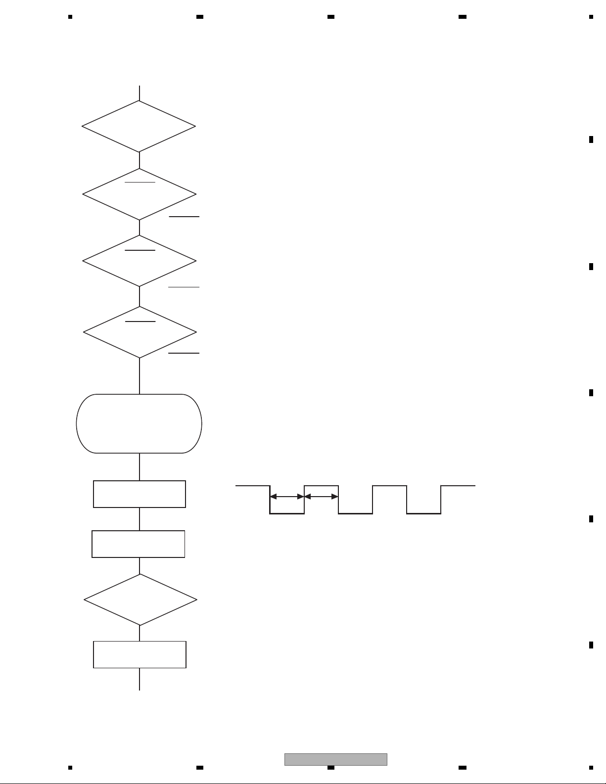
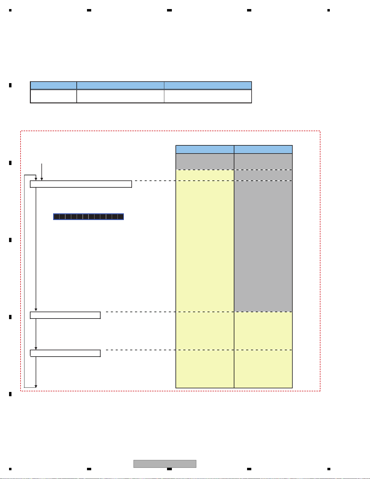
Vcc = 1.2 V
PVcc = 3.3 V
BSENS
Pin 90
ASENS
Pin 89
DSENS
Pin 34
BSENS = L
DSENS = L
Starts
communication
with Grille
microcomputer.
SWVDD <- H
Pin 1
Source keys
operative
Source ON
SYSPW <- H
Pin 8
300 ms
300 ms
In case of the above signal, the communication
with Grille microcomputer may fail.
If the time interval is not 300 msec, the oscillator
may be defective.
Completes power-on operation.
(After that, proceed to each source operation)
Power ON
ASENS = L
Vcc : Pin 12, 20, 43, 78, 86, 109
PVcc : Pin 3, 16, 28, 36, 48, 69, 82,101, 112
5. DIAGNOSIS
5.1 OPERATIONAL FLOWCHART
DEH-X2900UI/XNUC
11
1234
1234
C
D
F
A
B
E
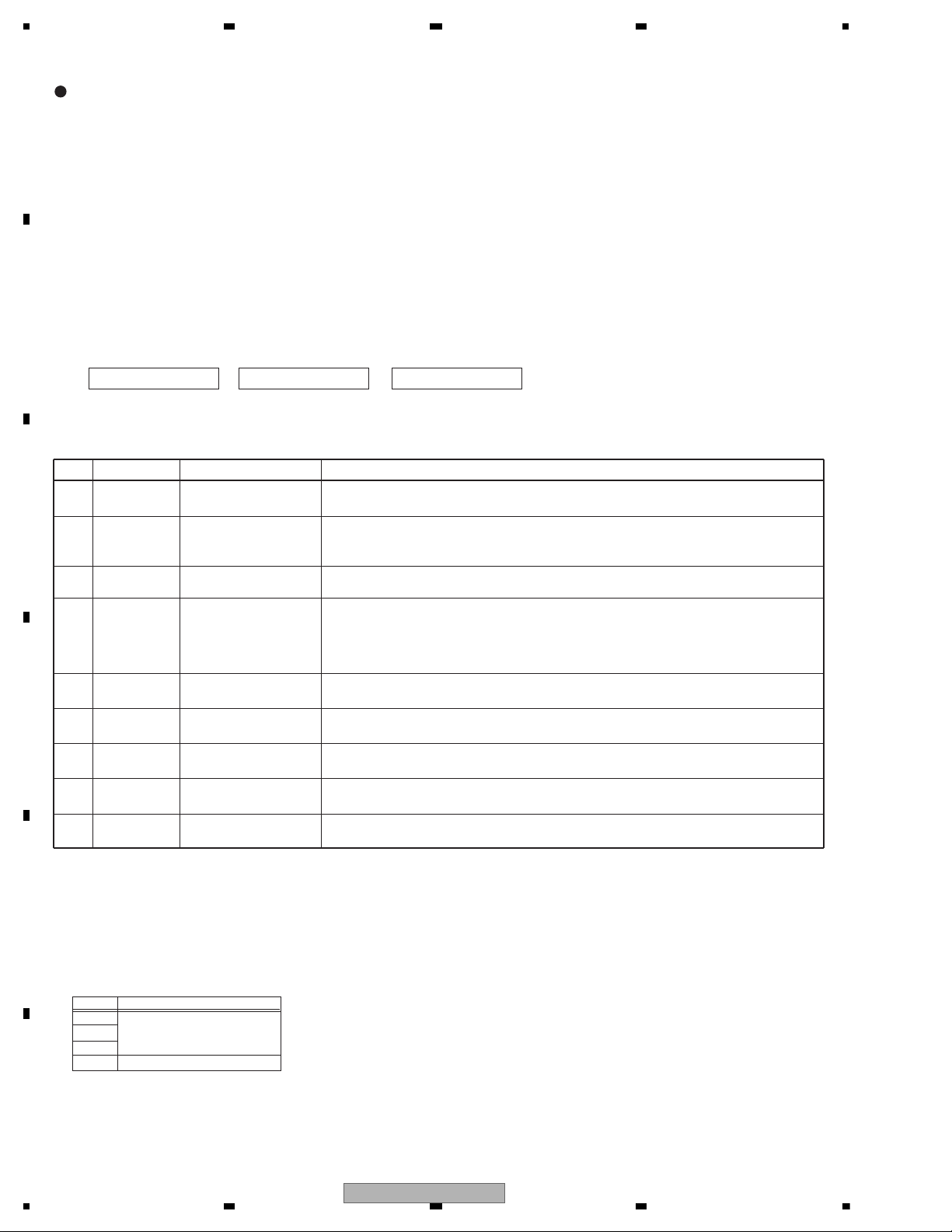
5.2 ERROR CODE LIST
8-digit display 6-digit display 4-digit display
ERROR-xx ERR-xx E-xx
(2) LIST OF CD ERROR CODES (Error Mode: 0xFD)
Code Classification
Error code to be displayed
Details and possible causes
10 Servo Carriage Home NG The pickup cannot move toward the inner track.
The CRG cannot move from the inner track.
--> Defective HOME SW; Failure in CRG movement.
07 Servo TOC reading NG TOC information cannot be read.
--> The partial disk or TOC content is illegal.
11 Servo Focus NG Focusing not available
--> Disc placed upside-down; Stains on the disc; excessive vibration.
17 Servo Setup NG The laser output cannot be adjusted. Focus can be easily lost.
--> Scratches or stains on the disc; excessive vibration.
15 Servo RF NG The digital signal from the disc cannot be detected.
--> A CD-R/RW disc that does not contain data loaded.
12 Servo Spindle Lock NG
Subcode NG
RF-amp NG
Spindle not locked. Subcode not readable.
Proper RF AMP gain not obtained.
--> Defective spindle; Scratches or stains on the disc; excessive vibration.
-->
A CD-R/RW disc that does not contain data loaded, or in a rare case, disc placed upside-down.
--> RF signal error.
30 Servo Search Time Out Failed to reach a target address. And, the search became a timeout.
--> Carriage/Tracking error; Scratches on the disc; Stains on the disc
50 Mechanism Load NG
Eject NG
Disc loading/ejection not completed
--> A foreign object inserted in the mechanism; Disc jammed.
51 Mechanism Failure in retried
turning for ejection
Disc could not be ejected even after disc turning had been retried.
--> A foreign object inserted in the mechanism; Disc jammed.
ERROR CODES
(1) DISPLAY METHOD
If “0xFD” error mode is displayed in CD MODE (CD MODE area for display), an error code will be displayed in the MIN (minute
display) and SEC (second display) areas.
The same code is displayed in the MIN and SEC areas.
The TNO area is blank (#0FFH), as it conventionally was.
• Display example of the head unit
Depending on the display capability of LCDs, the display format varies, as shown below. XX denotes an error number.
Note: In a case of an OEM product, the error display format is subject to the specifications used by the equipment
manufacturer.
If a CD memory device is inoperable, or operation of such media is stopped by an error, the error mode is established and a
cause of the error is displayed by an error code. Indication of error codes is intended to reduce the number of calls from
customers and facilitate failure analysis and repair work in servicing.
• The 2 high-order digits of an error code denote the main classification, shown below.
code classification
0x
1x Servo-related errors
3x
5x Mechanism-related errors
• How to restore from each error is shown below.
Servo-related errors(0X, 1X, 3X) : Servo-related errors CD Off, Eject, ACC Off, Back-up Off, Communication reset, Reset
Load NG/Eject NG(50) : Reload, Eject, ACC Off, Back-up Off, Communication reset, Reset
Failure in retried turning for ejection : CD On, Eject, ACC Off, Back-up Off, Communication reset, Reset
NOTES
• Indications of error codes are available only during disc operations, because CD operations are unavailable if a mechanical error is
generated.
• If the TOC cannot be read, It stops because of error 07.
• If you design a new head unit, be sure to use one of the display formats indicated in “Display example of the head unit.”
12
DEH-X2900UI/XNUC
5678
56
7
8
C
D
F
A
B
E
Common
AMP ERROR
This unit fails to operate or the speaker
connection is incorrect.
– Check the speaker connection.
– Check the power IC and its peripheral circuit.
NO XXXX (NO TITLE, for example)
There is no embedded text information.
– Switch the display or play another
track/file.
CD player
USB device/iPod
ERROR-07, 11, 12, 17, 30
The disc is dirty.
–Clean the disc.
The disc is scratched.
– Replace the disc.
ERROR-07, 10, 11, 12, 15, 17, 30, A0
There is an electrical or mechanical
error.
– Turn the ignition switch OFF and back
to ON, then back to the CD player.
ERROR-15
The inserted disc is blank.
– Replace the disc.
ERROR-23
Unsupported CD format.
– Replace the disc.
FORMAT READ
Sometimes there is a delay between the
start of playback and when you start to
hear any sound.
– Wait until the message disappears and
you hear sound.
NO AUDIO
The inserted disc does not contain any
playable files.
– Replace the disc.
SKIPPED
The inserted disc contains DRM
protected files.
– The protected files are skipped.
PROTECT
All the files on the inserted disc are
embedded with DRM.
– Replace the disc.
FORMAT READ
Sometimes there is a delay between the
start of playback and when you start to
hear any sound.
– Wait until the message disappears and
you hear sound.
NO AUDIO
There are no songs.
– Transfer the audio files to the USB
device and connect.
The connected USB device has security
enabled.
– Follow the USB device instructions to
disable the security.
SKIPPED
The connected USB device contains
DRM protected files.
– The protected files are skipped.
PROTECT
All the files on the connected USB
device are embedded with DRM.
– Replace the USB device.
N/A USB
The connected USB device is not
supported by this unit.
– Disconnect your device and replace it
with a compatible USB device.
HUB ERROR
The USB device connected via a USB
hub is not supported by this unit.
–Connect the USB device directly to this
unit using a USB cable.
CHECK USB
The USB connector or USB cable has
short-circuited.
– Check that the USB connector or USB
cable is not caught in something or
damaged.
The connected USB device consumes
more than maximum allowable current.
– Disconnect the USB device and do not
use it. Turn the ignition switch OFF
and back to ACC or ON. Connect only
compliant USB devices.
The iPod operates correctly but does
not charge.
– Make sure the connection cable for
the iPod has not shorted out (e.g., not
caught in metal objects). After
checking, turn the ignition switch OFF
and back to ON, or disconnect the
iPod and reconnect.
ERROR-19
Communication failed.
– Perform one of the following
operations, then return to the USB
source.
• Turn the ignition switch OFF and
back to ON.
• Disconnect the USB device.
• Change to a different source.
iPod failure.
– Disconnect the cable from the iPod.
Once the iPod’s main menu is
displayed, reconnect the iPod and
reset it.
ERROR-23
USB device was not formatted properly.
–Format the USB device with FAT12,
FAT16 or FAT32.
ERROR-16
The iPod firmware version is old.
– Update the iPod version.
iPod failure.
– Disconnect the cable from the iPod.
Once the iPod’s main menu is
displayed, reconnect the iPod and
reset it.
STOP
There are no songs in the current list.
– Select a list that contains songs.
NOT FOUND
No related songs.
– Transfer songs to the iPod.
NO BT DEVICE GO TO BT MENU TO
REGISTER
No Bluetooth device found.
– Connect the unit and iPod via
Bluetooth.
CONN. FAILED PRESS BAND KEY TO
RETRY
Bluetooth connection with iPod failed.
– Press BAND/ to make a
connection again.
DISCONNECTED PRESS BAND KEY TO
RETRY
Bluetooth connection with iPod failed.
Apps
NO BT DEVICE GO TO BT MENU TO
REGISTER
No Bluetooth device found.
– Connect the unit and the device via
Bluetooth.
CONN. FAILED PRESS BAND KEY TO
RETRY
Bluetooth connection failed.
DISCONNECTED PRESS BAND KEY TO
RETRY
Bluetooth connection failed.
CHECK APP
Connection to the application failed.
– Follow the instructions that appear on
the screen.
–Press BAND/ to make a
connection again.
– Press BAND / to make a
connection again.
– Press BAND / to make a
connection again.
START UP APP
The application has not started running
yet.
–Operate the mobile device to start up
the application.
Spotify
NO BT DEVICE GO TO BT MENU TO
REGISTER
No Bluetooth device found.
– Connect the unit and the device via
Bluetooth.
CONN. FAILED PRESS BAND KEY TO
RETRY
Bluetooth connection failed.
CHECK APP PRESS BAND KEY TO RETRY
Connection to the Spotify application
failed.
DISCONNECTED PRESS BAND KEY TO
RETRY
Bluetooth connection lost.
CHECK APP
Connection to the Spotify application
failed.
– Follow the instructions that appear on
the screen.
– Press BAND / to make a
connection again.
– Press BAND / to make a
connection again.
– Press BAND / to make a
connection again.
DEH-X2900UI/XNUC
13
1234
1234
C
D
F
A
B
E
Pandora
ERROR-19
Communication failed.
– Disconnect the cable from the device.
Once the device’s main menu is
displayed, reconnect the device and
reset it.
START UP APP
The Pandora application has not started
running yet.
– Start up the Pandora application.
RATING ERROR
The thumb rating operation was
disabled.
– Run the same command for another
track.
CAN'T SKIP
The skip operation was disabled.
– Run the same command for another
track.
TRY LATER
Unable to save thumb rating.
Unable to save BookMark.
Unable to add station.
– Try again later.
MAINTENANCE
Pandora system is undergoing
maintenance.
– Try again later.
SKIP LIMIT
Due to music licensing restrictions,
Pandora limits the total number of skips
per hour.
– Wait until Pandora allows you to skip
again.
UPDATE APP
This version of the Pandora application
is not supported.
– Connect a device that has a
compatible version of the Pandora
application installed.
LOGIN ERROR
Your Pandora account is not logged in.
– Disconnect the cable from the device,
and log in to your Pandora account.
Then reconnect the device.
CHECK DEVICE
Device error message displayed in the
Pandora application.
– Check the connected device.
PLEASE CREATE A STATION ON THE
PHONE
No station found.
– Create a station in the Pandora
application on your connected device.
SELECT STN
No station selected.
– Select a station.
NO BT DEVICE GO TO BT MENU TO
REGISTER
No Bluetooth device found.
–Connect the unit and the device via
Bluetooth.
CONN. FAILED PRESS BAND KEY TO
RETRY
Bluetooth connection failed.
connection again.
CHECK APP PRESS BAND KEY TO RETRY
Connection to the Pandora application
failed.
connection again.
– Press BAND / to make a
– Press BAND / to make a
– Press BAND / to make a
DISCONNECTED PRESS BAND KEY TO
RETRY
Bluetooth connection lost.
connection again.
STATION FULL
A new station cannot be added.
– Delete an old station to open a spot
for a new one.
CAN.T DELETE
The station could not be deleted.
– Run the same command for another
station.
NO NETWORK
The connected device is out of area.
– Connect the device to a network.
NO SERVICE IN THIS COUNTRY
The connected device is out of area.
– Connect the device to a network.
STN DELETED
The operation was disabled.
– Run the same command for another
station.
14
DEH-X2900UI/XNUC
5678
56
7
8
C
D
F
A
B
E
16
14
12
10 8
6
42
15
13
11
97
5
31
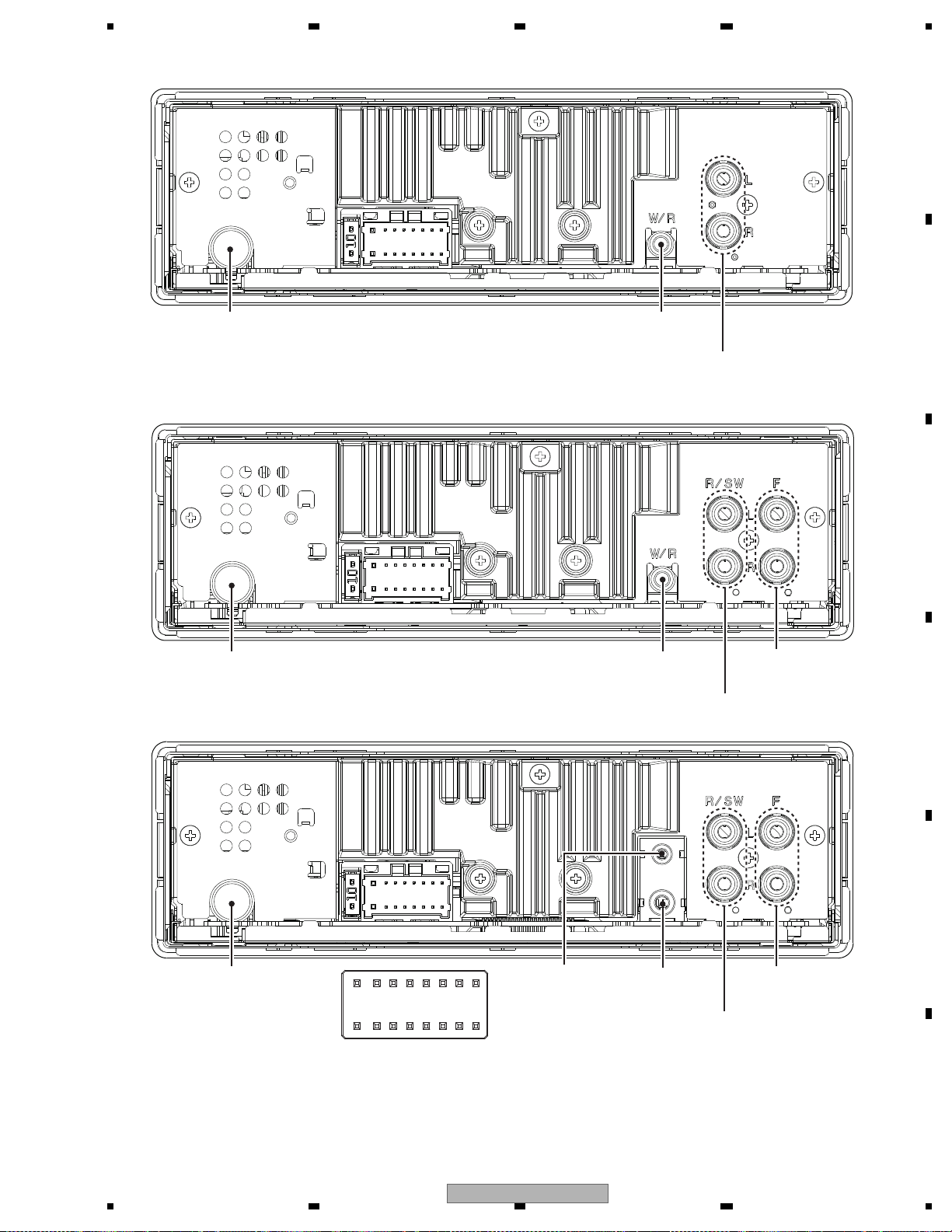
1 FL+
2 FR+
3 FL4 FR5 RL+
6 RR+
7 RL8 RR-
9 NC (Except for DEH-X2900UI/XNEW5)
9 TEL (DEH-X2900UI/XNEW5)
10 NC
11 ILL
12 NC
13 ACC
14 B.REM
15 B.UP
16 GND
MICROPHONE
INPUT
FM/AM
ANTENNA INPUT
WIRED
REMOTE
CONTROL
REAR OUTPUT or
SUBWOOFER OUTPUT
FM/AM
ANTENNA INPUT
WIRED
REMOTE
CONTROL
REAR OUTPUT or
SUBWOOFER OUTPUT
FRONT
OUTPUT
FM/AM
ANTENNA INPUT
WIRED
REMOTE
CONTROL
REAR OUTPUT or
SUBWOOFER OUTPUT
FRONT
OUTPUT
DEH-X2900UI/XNUC
DEH-X1/XNCS, DEH-X1/XNME, DEH-X2950UI/XNGS, DEH-X2990UI/XNID
DEH-X2900UI/XNEW5
5.3 CONNECTOR FUNCTION DESCRIPTION
DEH-X2900UI/XNUC
15
1234
1234
C
D
F
A
B
E
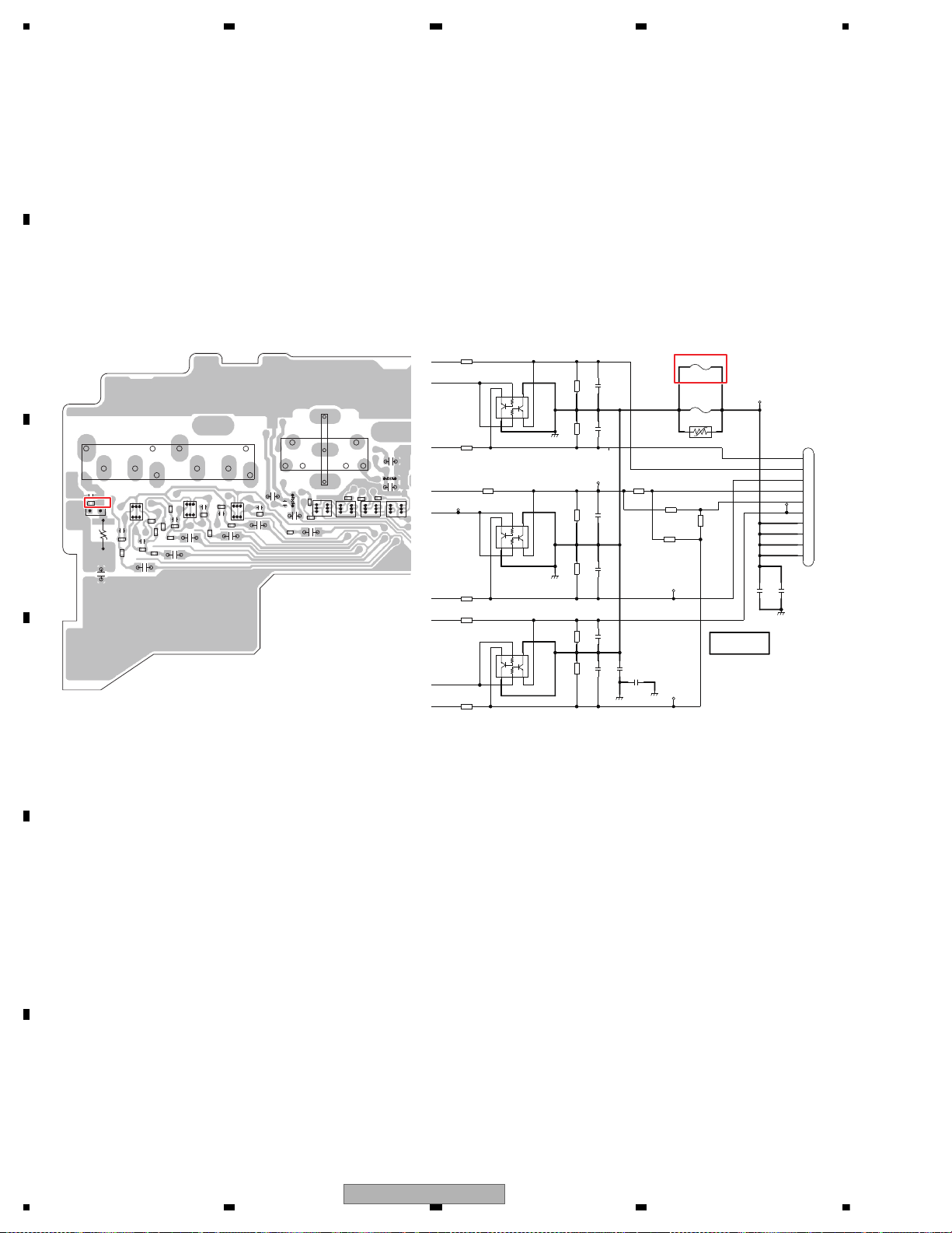
5.4 FUSE CHECK
*R753
22k
*FR
EMH53
*Q751
1234
5
6
R756
820
C758
NM
GND
R755
820
R757
22k
MUTE
*PR
C759
NM
C761
NM
*R754
22k
GND
EMH53
Q752
1
2
34
5
6
C757
NM
*C754
NM
GND
FL
*R751
820
C760
0.1u/10
*R752
820
RCAG
R758
22k
*C753
NM
*R761
22k
EMH53
*Q753
1234
5
6
*R762
22k
*C763
NM
*R759
820
*R760
820
*C762
NM
GND
PL
*R763
NM
*R764
0
*R765
0
*R766
NM
P751
NM
1
2
P753
CEK1404-A
12
C766
NM
GNDILM
*JA751
1
2
3
4
5
6
7
8
9
10
NM
P752
12
RCA OUT
SWR
SWL
FR
FL
CKB1109-A
[Ref.751-780]
3A
>
R800
1
P751
P752
P753
D812
D813
5
1
Q751
5
1
Q752
5
1
Q753
1
5
Q781
1
5
Q782
1
5
Q783
1
5
Q784
R751
R752
R753
R754
R755
R756
R757
R758
R759
R760
R761
R762
R763
R764
R765
R766
1
10
5
JA751
R789
C751
C752
C753
C754
C755
C756
C757
C758
R795
C759
R798
R799
C760
C761
C762
C763
C764
1
5
JA782
C765
JA781
C785
C786
C787
C788
- No sounds and display output of external unit (the condition when the fuse is blown)
This product may receive excessive current if the power line connection of the external product is incorrect, such as Ground
connection failure.
The fuse P753 on TUNER AMP UNIT is used to protect this product from this excessive current.
Even though the fuse is blown, the sounds of Pre-out output and AUX input are output properly and also other functions work
correctly.
However, you cannot turn on the external product connected to this product as the power is not supplied if the fuse is blown.
(The symptom in this case is the sounds of external product are not output on this product when the external product is
connected on a vehicle.)
If you find the symptoms above, check if the fuse is not blown.
If you replace to a new fuse and the fuse is blown again (you cannot turn on the power of external product), check the power
connection (Ground) of external product.
16
DEH-X2900UI/XNUC
5678
56
7
8
C
D
F
A
B
E
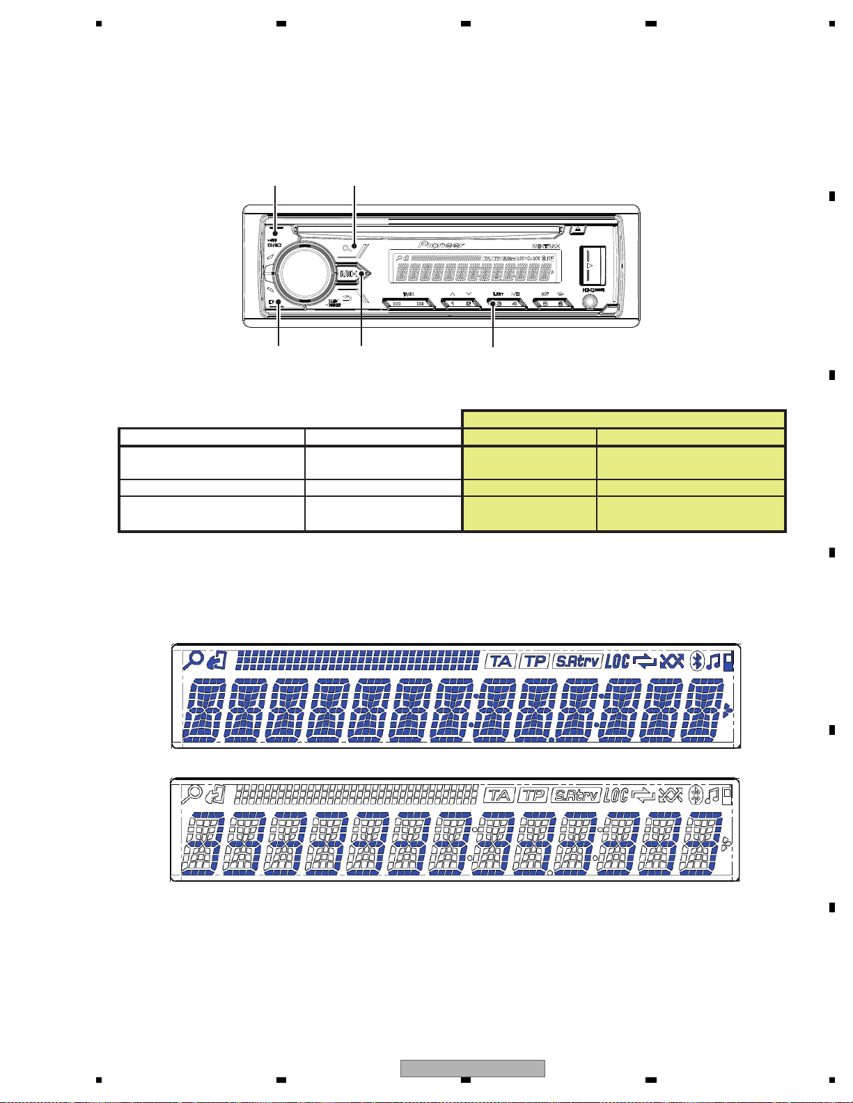
DISP 3
SOURCE
LIST
Press and hold "MIX and "LIST" buttons together, and turn BUP and ACC on.
[How to enter Test mode]
MIX
Status 1: Refer to "Draw 1" below.
States 2: All light off
Status 3: Refer to "Draw 2" below.
Draw 1
Draw 2
Grille condition
Conf. item Operate Show LCD ILM
All light up MIX + LIST Draw 1 RED
All light off SOURCE No light No light
Conf. Button feeling 3 Draw 2 BLUE
LCD States
6. SERVICE MODE
6.1 DISPLAY TEST MODE1
DEH-X2900UI/XNUC
17
1234
1234
C
D
F
A
B
E
6.2 DISPLAY TEST MODE2
* Initial
condition
$ PD number
For Ver.7.01, "701" is displayed
For PEA010A, "010A" is displayed
# System
microcomputer
version
S
$$$$
###
1 + 3
On (state when
entering test mode)
Press and hold "1" and "3" buttons together, and turn BUP and ACC on.
[Operation key]
[How to enter Test mode]
[Test items]
Start display test mode.
Press and hold "1" and "3" buttons together, and turn
BUP and ACC on.
Display is normally updated
Display update is stopped
Product operation is performed as usual, in appearance.
The screen gets still when entering this item.
On (an initial value)
On (lighting condition
of normal times)
On (an initial value or
setting value of default
menu)
On (an initial value or
setting value of default
menu)
On (an initial value or
setting value of default
menu)
Off
All off
All off
All off
Remarks
Key Illumination
Operation key Processing
Icon
Enter display test mode
Switch to next test mode
The information such as the system microcomputer version is checked.
Switching to next display
by pressing “ 1 ” + “ 3 ” buttons together.
Switching to next display
by pressing “ 1 ” + “ 3 ” buttons together.
Switching to next display
by pressing “ 1 ” + “ 3 ” buttons together.
System Version information is displayed.
18
DEH-X2900UI/XNUC
5678
56
7
8
C
D
F
A
B
E
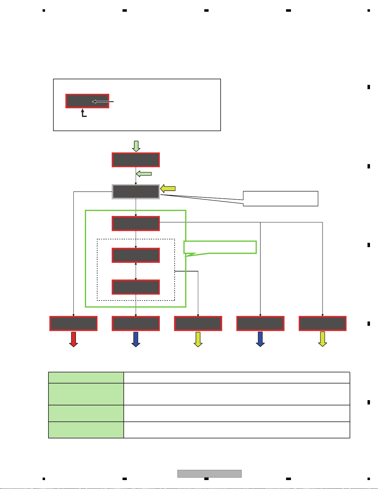
Overview
This mode is used for upgrading the MCU software of system using USB memory.
How to enter in USB rewriting mode
Press and hold "1" and "2" buttons together, and turn BUP and ACC on.
USB rewriting operation flow
Explanatory note
Screen display and ON/OFF of illumination
Characters displayed on the screen
Red frame: illumination lights up
Gray frame: illumination lights off
Blue characters: operation to be carried out by a user of USB rewriting function
Press and hold "1" and "2" buttons together, and turn BUP and ACC on.
Press LIST button
* After connecting USB memory in which upgrading file is stored, press LIST button.
(4) Retry count over
Retry rewriting
Check of upgrading file is started
(2) Upgrading file is not detected
Upgrading file error
After retryFirst time
Rewriting is started
Switched every
5 seconds
(3) Rewriting failed
(1) Rewriting succeeded
Result of rewriting
(1) Rewriting succeeded
(2) Upgrading file error
Upgrading file is not detected
(3) Rewriting failed
(4) Retry count over
FILE ERROR
DON'T STOP
PRG **/100
ERR->RETRYCAN'T UPDT
USB
START UPDT
CHECK FILE
In 5 seconds, usual operation
(OFF SOURCE)
As the reset is internally carried out,
display and illumination go out
In 5 seconds, usual operation
(OFF SOURCE)
In 5 seconds, rewriting
is retried
In 5 seconds, rewriting
is retried
Display is continued until
the power supply is turned
OFF
If the power supply is turned OFF
during rewriting, retry the rewriting.
Displayed when there is no upgrading file in USB memory or the data of upgrading file is different.
In 5 seconds, usual operation (OFF SOURCE) is started.
If the upgrading file error is detected or the upgrading file is not detected after the rewriting is retried, the rewriting is failed.
In 5 seconds, rewriting is retried.
Displayed when the retry becomes unavailable because the retry count is exceeded.
The display is continued until the power supply is turned OFF. If the power supply is turned ON again, the display is not changed.
Since USB Updating is disabled, it is necessary to replace Flash ROM UNIT.
Displayed when the writing of upgrading file in serial Flash is not normally terminated.
Or, displayed if the upgrading file error is detected or the upgrading file is not detected after the rewriting is retried.
In 5 seconds, rewriting is retried.
Displayed when USB rewriting is normally terminated.
In 5 seconds, usual operation (OFF SOURCE) is started.
ERR->RETRY
COMPLETE
6.3 SOFTWARE VERSION UP METHOD
DEH-X2900UI/XNUC
19
1234
1234
C
D
F
A
B
E
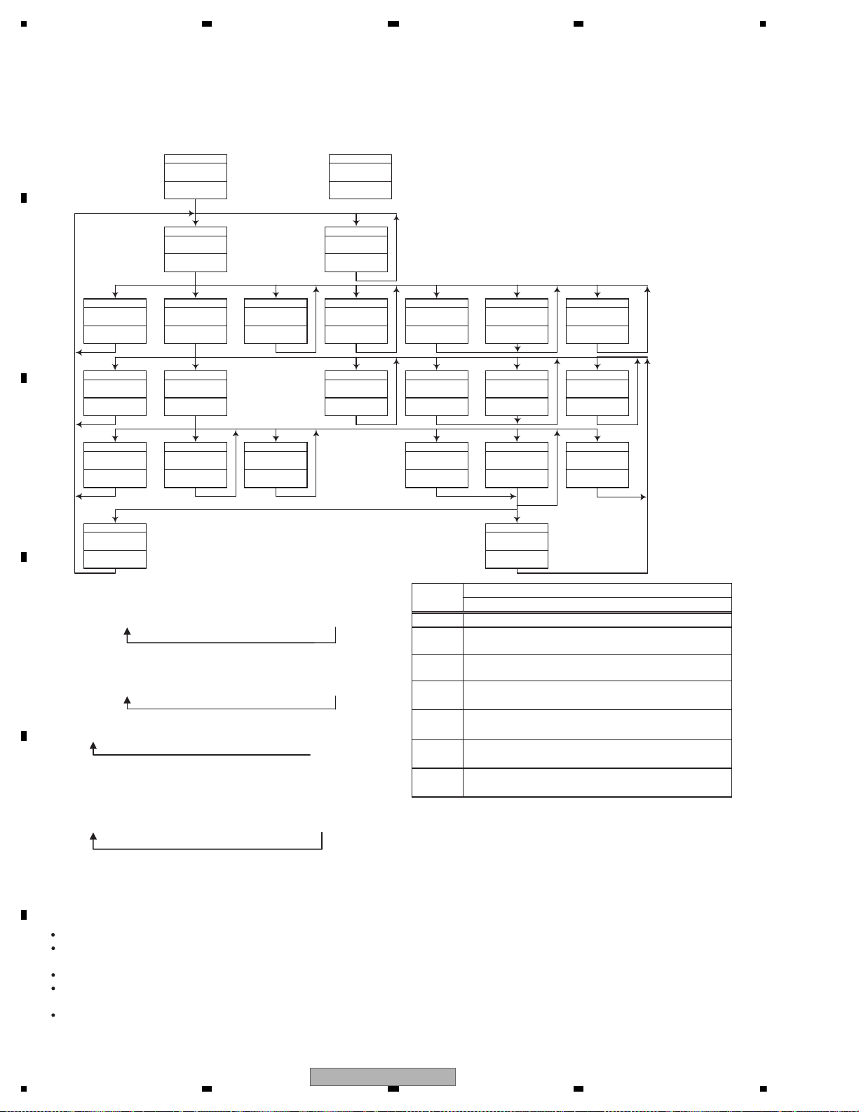
6.4 CD TEST MODE
- Flow Chart
To enter the test mode: [4] + [6] -> BUP + ACC ON
[CD] or [SOURCE]
Source ON
TRK MIN
[BAND]
Power Off
TRK MIN SEC
[BAND]
Power Off
TRK MIN SEC
[BAND]
Power Off
TRK MIN SEC
[BAND]
Power Off
TRK MIN SEC
[BAND]
Power On
(T.Offset is adjusted)
TRK MIN SEC
00 00 00
[3]
Focus Close
S curve check
TRK MIN SEC
91 91 91
[1]
T.Close & AGC
Applicable servomechanism
TRK MIN SEC
?tr ?min ?sec
[1]
F,T,RF AGC
F.Bias display switching
TRK MIN SEC
*5
[6]
Focus Mode switching
TRK MIN SEC
0X 0X 0X
[3] [>]
F,T AGC / F.Bias
RF AGC
TRK MIN SEC
?tr ?min ?sec
*2
[2]
TRK MIN SEC
GG GG GG
[1]
or 99 99 99
[3]
RF AGC coefficient display
TRK MIN SEC
?? ?? ??
[Key]
Contents
Display
RF AMP
Gain switching
Tracking Servo
Close
00 00 00
RF AGC /
*1
[>]
CRG +
00 00 00
or 99 99 99
[>]
CRG +
8X 8X 8X
or 9X 9X 9X
CRG/TR Jump +
TRK MIN SEC
?tr ?min ?sec
[<]
CRG -
00 00 00
or 99 99 99
[<]
CRG -
8X 8X 8X
or 9X 9X 9X
[<]
*4 *4
CRG/TR Jump -
TRK MIN SEC
?tr ?min ?sec?? ?? ??
[2]
Tracking Open
8X 8X 8X
or 9X 9X 9X
*6
[2]
Self-adjusting
switching
TRK MIN SEC
[2]
T.Balance adjustment /
T.BAL coefficient display
TRK MIN SEC
[2]
or 9X 9X 9X
*3*6
?? ?? ??
?? ?? ??
Tracking Open
8X 8X 8X
Operation
*1) TYP t + 6 dB t + 12 dB
TRK
MIN
SEC
TRK06MIN06SEC
06
TRK12MIN12SEC
12
[Key]
[BAND]
[>]
Power On/Off
CRG + / TR Jump +
Test Mode
(Direction of the external surface)
*2) Focus Close
TRK00MIN00SEC
TRK99MIN99SEC
(
t S. Curve t F EQ measurement setting
00
TRK
MIN01SEC
01
01
TRK02MIN02SEC
99)
02
CRG - / TR Jump -
[<]
(Direction of the internal surface)
[1]
T. CLS & AGC & Applicable servomechanism /
AGC,AGC display setting
[2]
*3) F.Offset Display t
RF.Offset
*4) 100TR Jump
*5) TRK/MIN/SEC
t F.AGC t T.AGC Gain t F.Bias t RF AGC
t
T.Offset Display t
Switch to the order
of the original
display
RF Gain switching / Offset adjustment display /
T.Balance adjustment / T. Open
[3]
F. Close,S. Curve / Rough Servo and RF AGC /
F,T,RF AGC
[6]
F. Mode switching / Tracking Close
*6) CRG motor voltage = 2 [V]
After the [EJECT] key is pressed keys other than the [EJECT] key should not be pressed, until disc ejection is complete.
When the key [2] or [3] is pressed during the Focus Search, the power supply should be immediately turned off (otherwise the lens sticks
to Wall, causing the actuator to be damaged).
In the case of 100TR Jump, the mechanism shall be set to the Tracking Close mode when the key is released.
When the power is turned on/off the gain of the RFAMP is reset to 0 dB. At the same time all the self-adjusting values shall return to the
default setting.
Do not do Tracking Servo Close before doing Focus Servo Close. (Because the overcurrent flows)
20
DEH-X2900UI/XNUC
 Loading...