

PIONEER CORPORATION 1-1, Shin-ogura, Saiwai-ku, Kawasaki-shi, Kanagawa 212-0031, Japan
PIONEER ELECTRONICS (USA) INC. P.O. Box 1760, Long Beach, CA 90801-1760, U.S.A.
PIONEER EUROPE NV Haven 1087, Keetberglaan 1, 9120 Melsele, Belgium
PIONEER ELECTRONICS ASIACENTRE PTE. LTD. 253 Alexandra Road, #04-01, Singapore 159936
PIONEER CORPORATION 2012
CD RDS RECEIVER
ORDER NO.
CRT4866
DEH-80PRS/XNUC
DEH-80PRS
/XNUC
DEH-80PRS/XNEW5
DEH-80PRS/XNES
This service manual should be used together with the following manual(s):
Model No. Order No. Mech. Module Remarks
CX-3287 CRT4759 S11.6STD CD Mech. Module : Circuit Descriptions, Mech. Descriptions, Disassembly
K-ZZZ FEB. 2012 Printed in Japan

1234
1234
C
D
F
A
B
E
SAFETY INFORMATION
CAUTION
Where in a manufacturer’s service documentation, for example in circuit diagrams or lists
of components, a symbol is used to indicate that a specific component shall be replaced only
by the component specified in that documentation for safety reasons, the following symbol shall
be used:
This service manual is intended for qualified service technicians; it is not meant for the casual do-it-yourselfer.
Qualified technicians have the necessary test equipment and tools, and have been trained to properly and safely repair
complex products such as those covered by this manual.
Improperly performed repairs can adversely affect the safety and reliability of the product and may void the warranty.
If you are not qualified to perform the repair of this product properly and safely, you should not risk trying to do so
and refer the repair to a qualified service technician.
CAUTION:
USE OF CONTROLS OR ADJUSTMENTS OR PERFORMANCE OF PROCEDURES OTHER THAN THOSE
SPECIFIED HEREIN MAY RESULT IN HAZARDOUS RADIATION EXPOSURE.
- Safety Precautions for those who Service this Unit.
When checking or adjusting the emitting power of the laser diode exercise caution in order to get safe, reliable
results.
Caution:
1. During repair or tests, minimum distance of 13 cm from the focus lens must be kept.
2. During repair or tests, do not view laser beam for 10 seconds or longer.
WARNING
This product may contain a chemical known to the State of California to cause cancer, or birth defects or
other reproductive harm.
Health & Safety Code Section 25249.6 - Proposition 65
WARNING!
The AEL (accessible emission level )of the laser power output is less than CLASS 1
but the laser component is capable of emitting radiation exceeding the limit for
CLASS 1.
A specially instructed person should do servicing operation of the apparatus.
CAUTION
This product is a class 1 laser product classified under the Safety of laser products, IEC
60825-1:2007, and contains a class 1M laser
module. To ensure continued safety, do not remove any covers or attempt to gain access to
the inside of the product. Refer all servicing to
qualified personnel.
CAUTION—CLASS 1M INVISIBLE LASER
RADIATION WHEN OPEN, DO NOT VIEW
DIRECTLY WITH OPTICAL INSTRUMENTS.
2
DEH-80PRS/XNUC
5 678
56
7
8
C
D
F
A
B
E
Laser diode characteristics
Wave length : 785 nm to 814 nm
Maximum output : 1 190 µW(Emitting period : unlimited)
Additional Laser Caution
Transistors Q101 in PCB drive the laser diodes.
When Q101 is shorted between their terminals, the laser diodes will radiate beam.
If the top cover is removed with no disc loaded while such short-circuit is continued,
the naked eyes may be exposed to the laser beam.
CAUTION
Danger of explosion if battery is incorrectly replaced.
Replaced only with the same or equivalent type recommended by the manufacturer.
Discord used batteries according to the manufacturer's instructions.
DEH-80PRS/XNUC
3

1234
1234
C
D
F
A
B
E
CONTENTS
SAFETY INFORMATION..................................................................................................................................... 2
1. SERVICE PRECAUTIONS............................................................................................................................... 5
1.1 SERVICE PRECAUTIONS ........................................................................................................................ 5
1.2 NOTES ON SOLDERING .......................................................................................................................... 6
2. SPECIFICATIONS............................................................................................................................................ 7
2.1 SPECIFICATIONS ..................................................................................................................................... 7
2.2 DISC/CONTENT FORMAT ...................................................................................................................... 13
3. BASIC ITEMS FOR SERVICE........................................................................................................................ 14
3.1 CHECK POINTS AFTER SERVICING..................................................................................................... 14
3.2 PCB LOCATIONS .................................................................................................................................... 14
3.3 JIGS LIST ................................................................................................................................................ 15
3.4 CLEANING............................................................................................................................................... 15
4. BLOCK DIAGRAM.......................................................................................................................................... 16
5. DIAGNOSIS.................................................................................................................................................... 20
5.1 OPERATIONAL FLOWCHART................................................................................................................ 20
5.2 ERROR CODE LIST ................................................................................................................................ 21
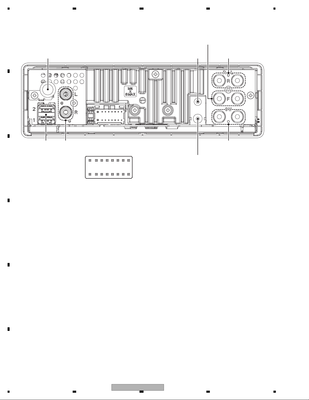
5.3 CONNECTOR FUNCTION DESCRIPTION............................................................................................. 24
6. SERVICE MODE ............................................................................................................................................ 25
6.1 DISPLAY TEST MODE ............................................................................................................................ 25
6.2 CD TEST MODE...................................................................................................................................... 28
7. DISASSEMBLY .............................................................................................................................................. 29
8. EACH SETTING AND ADJUSTMENT ........................................................................................................... 33
8.1 CD ADJUSTMENT................................................................................................................................... 33
8.2 CHECKING THE GRATING AFTER CHANGING THE PICKUP UNIT.................................................... 34
8.3 PCL OUTPUT CONFIRMATION.............................................................................................................. 36
9. EXPLODED VIEWS AND PARTS LIST.......................................................................................................... 38
9.1 PACKING ................................................................................................................................................. 38
9.2 EXTERIOR............................................................................................................................................... 42
9.3 CD MECHANISM MODULE..................................................................................................................... 44
10. SCHEMATIC DIAGRAM............................................................................................................................... 46
10.1 TUNER AMP UNIT (SYSTEM BLOCK) (GUIDE PAGE)........................................................................ 46
10.2 TUNER AMP UNIT (MEDIA BLOCK) (GUIDE PAGE) ........................................................................... 52
10.3 TUNER AMP UNIT (DSP BLOCK) (GUIDE PAGE) ............................................................................... 58
10.4 TUNER AMP UNIT (POWER SUPPLY BLOCK) (GUIDE PAGE).......................................................... 64
10.5 KEYBOARD UNIT.................................................................................................................................. 70
10.6 CD CORE UNIT (S11.6STD) ................................................................................................................. 72
10.7 PANEL UNIT .......................................................................................................................................... 74
10.8 WAVEFORMS ........................................................................................................................................ 75
11. PCB CONNECTION DIAGRAM.................................................................................................................... 78
11.1 TUNER AMP UNIT................................................................................................................................. 78
11.2 KEYBOARD UNIT .................................................................................................................................. 82
11.3 CD CORE UNIT (S11.6STD).................................................................................................................. 84
11.4 PANEL UNIT .......................................................................................................................................... 86
12. ELECTRICAL PARTS LIST .......................................................................................................................... 87
4
DEH-80PRS/XNUC
5 678
56
7
8
C
D
F
A
B
E
1. You should conform to the regulations governing the product (safety, radio and noise, and other
regulations), and should keep the safety during servicing by following the safety instructions
described in this manual.
2. Before disassembling the unit, be sure to turn off the power. Unplugging and plugging the connectors
during power-on mode may damage the ICs inside the unit.
3. To protect the pickup unit from electrostatic discharge during servicing, take an appropriate treatment
(shorting-solder) by referring to "the DISASSEMBLY".
4. After replacing the pickup unit, be sure to check the grating.
5. Be careful in handling ICs. Some ICs such as MOS type are so fragile that they can be damaged by
electrostatic induction.
6. area and a heat sink becomes hot areas. Be careful not to burn yourself.
7. The RESET button is at the back of the Detach Grille.
Note that the audio settings cannot be deleted by a hard reset.
Reset the audio settings from the initial setting menu.
8. Be careful not to damage the Knob for the Slide Switches (S351, S601) at the bottom of the Tuner Amp Unit while
handling it or attaching the Bottom Plate.
9. The part listed below is difficult to replace as a discrete component part.
When the part listed in the table is defective, replace whole Assy.
10. RGB LED's (D1831 - D1864) are used for the illumination of the Keyboard Unit. To avoid the color heterogeneity, replace
the whole of the Keyboard Unit, even if only one of RGB LED's was defective.
TUNER AMP UNIT IC851 LT1912EMSE Heat pad
1. SERVICE PRECAUTIONS
1.1 SERVICE PRECAUTIONS
DEH-80PRS/XNUC
5

1234
1234
C
D
F
A
B
E
1.2 NOTES ON SOLDERING
For environmental protection, lead-free solder is used on the printed circuit boards mounted in this unit.
Be sure to use lead-free solder and a soldering iron that can meet specifications for use with lead-free solders for repairs
accompanied by reworking of soldering.
Compared with conventional eutectic solders, lead-free solders have higher melting points, by approximately 40 C.
Therefore, for lead-free soldering, the tip temperature of a soldering iron must be set to around 373 C in general, although
the temperature depends on the heat capacity of the PC board on which reworking is required and the weight of the tip of
the soldering iron.
Compared with eutectic solders, lead-free solders have higher bond strengths but slower wetting times and higher melting
temperatures (hard to melt/easy to harden).
The following lead-free solders are available as service parts:
Parts numbers of lead-free solder:
GYP1006 1.0 in dia.
GYP1007 0.6 in dia.
GYP1008 0.3 in dia.
6
DEH-80PRS/XNUC

5 678
56
7
8
C
D
F
A
B
E
• DEH-80PRS/XNUC
General
Power source............................ 14. 4 V DC (10.8 V to 15.1 V
allowable)
Grounding system.................. Negative type
Maximum current consumption
................................................... 10. 0 A
Dimensions (W × H × D):
DIN
Chassis.................... 178 mm × 50 m m ×
165 mm
(7 in. × 2 in. × 6-1/2in.)
Nose.......................... 188 mm × 58 m m × 17 mm
(7-3/8 in.× 2-1/4 in.× 5/8 in.)
D
Chassis.................... 178 mm × 50 m m ×
165 mm
(7 in.× 2 in.× 6-1/2 in.)
Nose.......................... 170 mm × 46 m m × 17 mm
(6-3/4 in.× 1-3/4 in.× 5/8 in.)
Weight ........................................ 1.2 kg (2.6 lbs)
Audio
Maximum power output ....... 50 W × 4
Continuous power output ... 22 W × 4 (50 Hz to
15 000 Hz, 5% THD,
4 Ω load, both channels dri-
ven)
Load impedance ..................... 4 Ω to 8 Ω ×4
Preout maximum output level
.................................................. 5.0 V
Loudness contour .................. +10 dB (1 00 Hz), +6.5 dB
(10 kHz) (volume:–30 dB)
Equalizer (Left/Right independent 16-Band Graphic
Equalizer):
Frequency......................... 20 Hz/31.5 Hz/50 Hz/80 Hz/
125 Hz/200 Hz/315 Hz/
500 Hz/800 Hz/1.25 kHz/
2 kHz/3.15 kHz/5 kHz/8 kHz/
12.5 kHz/20 kHz
Equalization range........ ±12 dB (2 dB step)
Auto equalizer:
(Front & rear & subwoofer/High & mid & low)
Frequency......................... 20 Hz/31.5 Hz/50 Hz/80 Hz/
125 Hz/200 Hz/315 Hz/
500 Hz/800 Hz/1.25 kHz/
2 kHz/3.15 kHz/5 kHz/8 kHz/
12.5 kHz/20 kHz
Equalization range........ +6 dB t o –1 2 dB (2 dB step)
Network (standard mode):
HPF (front)
Frequency............... 50 Hz/63 Hz/80 Hz/100Hz/
125 Hz/160 Hz/200 Hz
Slope......................... 0 ( Pass)/–6dB/oct./–12 dB/
oct.
Gain........................... 0 dB t o –24 dB/Mute (1 dB
step)
HPF (rear)
Frequency............... 50 Hz/63 Hz/80 Hz/100Hz/
125 Hz/160 Hz/200 Hz
Slope......................... 0 ( Pass)/–6dB/oct./–12 dB/
oct.
Gain........................... +6 dB to –24 dB/Mute (1
dB step)
Subwoofer (stereo/mono):
Frequency............... 50 Hz/63 Hz/80 Hz/100Hz/
125 Hz/160 Hz/200 Hz
Slope......................... –6 dB/oct./–12 dB/oct./–
18 dB/oct.
Gain........................... +6 dB to –24 dB/Mute (1
dB step)
Phase ....................... Normal/Reverse
Network (3-way network mode):
High HPF:
Frequency................1. 25 kHz/1.6 kHz/2 kHz/
2.5 kHz/3.15 kHz/4 kHz/
5 kHz/6.3 kHz/8 kHz/10 kHz/
12.5 kHz
Slope......................... –6 dB/oct./–12 dB/oct./–
18 dB/oct./–24 dB/oct.
Gain........................... 0 dB t o –24 dB/Mute (1 dB
step)
Phase ....................... Normal/Reverse
Mid HPF/LPF:
F
requency (LPF)...1.25 kHz/1.6kHz/2 kHz/
2.5 kHz/3.15 kHz/4 kHz/
5 kHz/6.3 kHz/8 kHz/10 kHz/
12.5 kHz
Frequency (HPF)
............................... 25 Hz/31.5 Hz/40 Hz/50Hz/
63 Hz/80 Hz/100 Hz/125 Hz/
160 Hz/200 Hz/250 Hz
Slope (LPF)............ 0 (Pass)/–6 dB/oct./–12 dB/
oct./–18 dB/oct./–24 dB/oct.
Slope (HPF)........... 0 ( Pass)/–6 dB/oct./–12dB/
oct./–18 dB/oct./–24 dB/oct.
Gain........................... 0 dB t o –24 dB/Mute (1 dB
step)
Phase ....................... Normal/Reverse
Low LPF (stereo/mono):
Frequency............... 25 Hz/31.5 Hz/40 Hz/50Hz/
63 Hz/80 Hz/100 Hz/125 Hz/
160 Hz/200 Hz/250 Hz
Slope......................... –12 dB/oct./–18 dB/oct./–
24 dB/oct./–30 dB/oct./–
36 dB/oct.
Backup current ................... 5.0 mA or less
2. SPECIFICATIONS
2.1 SPECIFICATIONS
DEH-80PRS/XNUC
7

1234
1234
C
D
F
A
B
E
Gain........................... +6 dB to –24 dB/Mute (1
dB step)
Phase ....................... Normal/Reverse
CD player
System........................................ Compact disc audio system
Usable discs ............................ Compact disc
Signal-to-noise ratio.............. 10 5 dB (1 kH z) (IHF- A net-
work)
Number of channels ............. 2 (stereo)
MP3 decoding format .......... MPEG-1 & 2 Audio Layer 3
WMA decoding format ........ Ver. 7, 7.1, 8, 9, 10, 11 , 12
(2 ch audio)
(Windows Media Player)
AAC decoding format........... MPEG-4 AAC (iTunes en-
coded only) (.m4a)
(Ver. 10.4 and earlier)
WAV signal format................. Linear PCM & MS ADPCM
(Non-compressed)
USB
USB standard specification
................................................... USB 2 .0 full spee d
Maximum current supply .... 1 A
USB Class................................. MSC (Mass Storage Class)
File system................................ FAT12, FAT16, FAT32
MP3 decoding format .......... MPEG-1 & 2 Audio Layer 3
WMA decoding format ........ Ver. 7, 7.1, 8, 9, 10, 11 , 12
(2 ch audio)
(Windows Media Player)
AAC decoding format........... MPEG-4 AAC (iTunes en-
coded only) (.m4a)
(Ver. 10.4 and earlier)
WAV signal format................. Linear PCM & MS ADPCM
(Non-compressed)
SD
Compatible physical format
................................................... Version 2.00
Maximum memory capacity
................................................... 32 GB (fo r SD an d SDH C)
File system................................ FAT12, FAT16, FAT32
MP3 decoding format .......... MPEG-1 & 2 Audio Layer 3
WMA decoding format ........ Ver. 7, 7.1, 8, 9, 10, 11 , 12
(2 ch audio)
(Windows Media Player)
AAC decoding format........... MPEG-4 AAC (iTunes en-
coded only) (.m4a)
(Ver. 10.4 and earlier)
WAV signal format................. Linear PCM & MS ADPCM
(Non-compressed)
FM tuner
Frequency range..................... 87.9 MHz to 107.9 MHz
Usable sensitivity.................... 9 dBf (0.8 µV/75 Ω, mono,
S/N: 30 dB)
Signal-to-noise ratio.............. 72 dB (IHF-A network)
AM tuner
Frequency range..................... 530 kH z to 1 7 10 kHz
Usable sensitivity.................... 25 µV (S/N: 20 dB)
Signal-to-noise ratio.............. 62 dB (IHF-A network)
Bluetooth
Version........................................ Bluetooth 3.0 certified
Output power ........................... +4 d Bm Maximum
(Power class 2)
CEA2006 Specifications
Powe r out put ............................ 14 W RMS × 4 Ch annels
(4 Ω and
1 % THD+N)
S/N ratio ..................................... 91 dBA (reference: 1 W into
4 Ω)
Note
Specifications and the design are subject to modifications without notice.
8
DEH-80PRS/XNUC

5 678
56
7
8
C
D
F
A
B
E
General
Power source............................ 14. 4 V DC (10.8 V to 15.1 V
allowable)
Grounding system.................. Negative type
Maximum current consumption
................................................... 10. 0 A
Dimensions (W × H × D):
DIN
Chassis.................... 178 mm × 50 m m ×
165 mm
Nose.......................... 188 mm × 58 m m × 17 mm
D
Chassis.................... 178 mm × 50 m m ×
165 mm
Nose.......................... 170 mm × 46 m m × 17 mm
Weight .........................................1.2 k g
Audio
Maximum power output ....... 50 W × 4
Continuous power output ... 22 W × 4 (50 Hz to
15 000 Hz, 5% THD,
4 Ω load, both channels dri-
ven)
Load impedance ..................... 4 Ω to 8 Ω×4
Preout maximum output level
................................................... 5.0 V
Loudness contour .................. +10 dB (1 00 Hz), +6.5 dB
(10 kHz) (volume:–30 dB)
Equalizer (Left/Right independent 16-Band Graphic
Equalizer):
Frequency......................... 20 Hz/31.5 Hz/50 Hz/80 Hz/
125 Hz/200 Hz/315 Hz/
500 Hz/800 Hz/1.25 kHz/
2 kHz/3.15 kHz/5 kHz/8 kHz/
12.5 kHz/20 kHz
Equalization range....... ±12 dB (2 dB step)
Auto equalizer:
(Front & rear & subwoofer/High & mid & low)
Frequency......................... 20 Hz/31.5 Hz/50 Hz/80 Hz/
125 Hz/200 Hz/315 Hz/
500 Hz/800 Hz/1.25 kHz/
2 kHz/3.15 kHz/5 kHz/8 kHz/
12.5 kHz/20 kHz
Equalization range....... +6 d B to – 12 dB ( 2 d B step)
Network (standard mode):
HPF (front)
Frequency............... 50 Hz/63 Hz/80 Hz/100Hz/
125 Hz/160 Hz/200 Hz
Slope......................... 0 ( Pass)/–6dB/oct./–12 dB/
oct.
Gain........................... 0 dB t o –24 dB/Mute (1 dB
step)
HPF (rear)
Frequency............... 50 Hz/63 Hz/80 Hz/100Hz/
125 Hz/160 Hz/200 Hz
Slope......................... 0 ( Pass)/–6dB/oct./–12 dB/
oct.
Gain........................... +6 dB to –2 4 dB/Mute (1
dB step)
Subwoofer (stereo/mono):
Frequency............... 50 Hz/63 Hz/80 Hz/100Hz/
125 Hz/160 Hz/200 Hz
Slope......................... –6 dB/oct./–12 dB/oct./–
18 dB/oct.
Gain........................... +6 dB to –2 4 dB/Mute (1
dB step)
Phase ....................... Normal/Reverse
Network (3-way network mode):
High HPF:
Frequency................1. 25 kHz/1.6 kHz/2 kHz/
2.5 kHz/3.15 kHz/4 kHz/
5 kHz/6.3 kHz/8 kHz/10 kHz/
12.5 kHz
Slope......................... –6 dB/oct./–12 dB/oct./–
18 dB/oct./–24 dB/oct.
Gain........................... 0 dB t o –24 dB/Mute (1 dB
step)
Phase ....................... Normal/Reverse
Mid
HPF/LPF:
Frequency (LPF)...1.25 kHz/1.6 kHz/2 kHz/
2.5 kHz/3.15 kHz/4 kHz/
5 kHz/6.3 kHz/8 kHz/10 kHz/
12.5 kHz
Frequency (HPF)
................................ 25 Hz/31.5 Hz/40Hz/50 Hz/
63 Hz/80 Hz/100 Hz/125 Hz/
160 Hz/200 Hz/250 Hz
Slope (LPF)............ 0 (Pass)/–6 dB/oct./–12 dB/
oct./–18 dB/oct./–24 dB/oct.
Slope (HPF)........... 0 ( Pass)/–6 dB/oct./–12dB/
oct./–18 dB/oct./–24 dB/oct.
Gain........................... 0 dB t o –24 dB/Mute (1 dB
step)
Phase ....................... Normal/Reverse
Low LPF (stereo/mono):
Frequency............... 25 Hz/31.5 Hz/40 Hz/50Hz/
63 Hz/80 Hz/100 Hz/125 Hz/
160 Hz/200 Hz/250 Hz
Slope......................... –12 dB/oct./–18 dB/oct./–
24 dB/oct./–30 dB/oct./–
36 dB/oct.
Gain........................... +6 dB to –2 4 dB/Mute (1
dB step)
Phase ....................... Normal/Reverse
• DEH-80PRS/XNEW5
Backup current ................... 5.0 mA or less
DEH-80PRS/XNUC
9

1234
1234
C
D
F
A
B
E
CD player
System........................................ Compact disc audio system
Usable discs ............................ Compact disc
Signal-to-noise ratio.............. 10 5 dB (1 kH z) (IEC-A net-
work)
Number of channels ............. 2 (stereo)
MP3 decoding format .......... MPEG-1 & 2 Audio Layer 3
WMA decoding format ........ Ver. 7, 7.1, 8, 9, 10, 11 , 12
(2 ch audio)
(Windows Media Player)
AAC decoding format........... MPEG-4 AAC (iTunes en-
coded only) (.m4a)
(Ver. 10.4 and earlier)
WAV signal format................. Linear PCM & MS ADPCM
(Non-compressed)
USB
USB standard specification
................................................... USB 2 .0 full speed
Maximum current supply .... 1 A
USB Class................................. MSC (Mass Storage Class)
File system................................ FAT12, FAT16, FAT32
MP3 decoding format .......... MPEG-1 & 2 Audio Layer 3
WMA decoding format ........ Ver. 7, 7.1, 8, 9, 10, 11 , 12
(2 ch audio)
(Windows Media Player)
AAC decoding format........... MPEG-4 AAC (iTunes en-
coded only) (.m4a)
(Ver. 10.4 and earlier)
WAV signal format................. Linear PCM & MS ADPCM
(Non-compressed)
SD
Compatible physical format
................................................... Version 2.00
Maximum memory capacity
................................................... 32 GB (fo r SD an d SDH C)
File system................................. FAT12, FAT16, FAT32
MP3 decoding format .......... MPEG-1 & 2 Audio Layer 3
WMA decoding format ........ Ver. 7, 7.1, 8, 9, 10, 11 , 12
(2 ch audio)
(Windows Media Player)
AAC decoding format........... MPEG-4 AAC (iTunes en-
coded only) (.m4a)
(Ver. 10.4 and earlier)
WAV signal format................. Linear PCM & MS ADPCM
(Non-compressed)
FM tuner
Frequency range..................... 87.5 MHz to 108.0 MHz
Usable sensitivity.................... 9 dBf (0.8 µV/75 Ω, mono,
S/N: 30 dB)
Signal-to-noise ratio.............. 72 dB (IEC-A network)
MW tuner
Frequency range..................... 531 kHz to 1 602 kHz
Usable sensitivity.................... 25 µV (S/N: 20 dB)
Signal-to-noise ratio.............. 62 dB (I EC-A network)
LW tuner
Frequency range..................... 153 kHz to 28 1 kHz
Usable sensitivity.................... 28 µV (S/N: 20 dB)
Signal-to-noise ratio.............. 62 dB (I EC-A network)
Bluetooth
Version........................................ Bluetooth 3.0 certified
Output power ........................... +4 d Bm Maximum
(Power class 2)
Note
Specifications and the design are subject to modifications without notice.
10
DEH-80PRS/XNUC

5 678
56
7
8
C
D
F
A
B
E
• DEH-80PRS/XNES
General
Rated power source...............1 4.4 V DC
(allowable voltage range:
12.0 V to 14.4 V DC)
Grounding system.................. Negative type
Maximum current consumption
................................................... 10. 0 A
Dimensions (W × H × D):
DIN
Chassis.................... 178 mm × 50 m m ×
165 mm
Nose.......................... 188 mm × 58 m m × 17 mm
D
Chassis.................... 178 mm × 50 m m ×
165 mm
Nose.......................... 170 mm × 46 m m × 17 mm
Weight ........................................ 1.2 kg
Audio
Maximum power output ....... 50 W × 4
Continuous power output ... 22 W × 4 (50 Hz to
15 000 Hz, 5% THD,
4 Ω load, both channels dri-
ven)
Load impedance ..................... 4 Ω to 8 Ω×4
Preout maximum output level
................................................... 5.0 V
Loudness contour .................. +10 dB (1 00 Hz), +6.5 dB
(10 kHz) (volume:–30 dB)
Equalizer (Left/Right independent 16-Band Graphic
Equalizer):
Frequency........................ 20 Hz/31.5 Hz/50 Hz/80Hz/
125 Hz/200 Hz/315 Hz/
500 Hz/800 Hz/1.25 kHz/
2 kHz/3.15 kHz/5 kHz/8 kHz/
12.5 kHz/20 kHz
Equalization range........ ±12 dB (2 dB step)
Auto equalizer:
(Front & rear & subwoofer/High & mid & low)
Frequency........................ 20 Hz/31.5 Hz/50 Hz/80Hz/
125 Hz/200 Hz/315 Hz/
500 Hz/800 Hz/1.25 kHz/
2 kHz/3.15 kHz/5 kHz/8 kHz/
12.5 kHz/20 kHz
Equalization range........ +6 dB t o –1 2 dB (2 dB step)
Network (standard mode):
HPF (front)
Frequency............... 50 Hz/63 Hz/80 Hz/100Hz/
125 Hz/160 Hz/200 Hz
Slope........................ 0 (Pass)/–6 dB/oct./–12 dB/
oct.
Gain........................... 0 dB t o –24 dB/Mute (1 dB
step)
HPF (rear)
Frequency............... 50 Hz/63 Hz/80 Hz/100Hz/
125 Hz/160 Hz/200 Hz
Slope......................... 0 ( Pass)/–6dB/oct./–12 dB/
oct.
Gain........................... +6 dB to –24 dB/Mute (1
dB step)
Subwoofer (stereo/mono):
Frequency............... 50 Hz/63 Hz/80 Hz/100Hz/
125 Hz/160 Hz/200 Hz
Slope......................... –6 dB/oct./–12 dB/oct./–
18 dB/oct.
Gain........................... +6 dB to –24 dB/Mute (1
dB step)
Phase ....................... Normal/Reverse
Network (3-way network mode):
High HPF:
Frequency............... 1. 25 kHz/1.6 kHz/2 kHz/
2.5 kHz/3.15 kHz/4 kHz/
5 kHz/6.3 kHz/8 kHz/10 kHz/
12.5 kHz
Slope......................... –6 dB/oct./–12 dB/oct./–
18 dB/oct./–24 dB/oct.
Gain.......................... 0 dB t o –24 dB/Mute (1 dB
step)
Phase .......................
Normal/Reverse
Mid
HPF/LPF:
Frequency (LPF)...1.25 kHz/1.6 kHz/2 kHz/
2.5 kHz/3.15 kHz/4 kHz/
5 kHz/6.3 kHz/8 kHz/10 kHz/
12.5 kHz
Frequency (HPF)
............................... 25 Hz/31.5 Hz/40 Hz/50Hz/
63 Hz/80 Hz/100 Hz/125 Hz/
160 Hz/200 Hz/250 Hz
Slope (LPF)............ 0 (Pass)/–6 dB/oct./–12 dB/
oct./–18 dB/oct./–24 dB/oct.
Slope (HPF)........... 0 ( Pass)/–6 dB/oct./–12dB/
oct./–18 dB/oct./–24 dB/oct.
Gain.......................... 0 dB t o –24 dB/Mute (1 dB
step)
Phase ....................... Normal/Reverse
Low LPF (stereo/mono):
Frequency............... 25 Hz/31.5 Hz/40 Hz/50Hz/
63 Hz/80 Hz/100 Hz/125 Hz/
160 Hz/200 Hz/250 Hz
Slope......................... –12 dB/oct./–18 dB/oct./–
24 dB/oct./–30 dB/oct./–
36 dB/oct.
Gain........................... +6 dB to –24 dB/Mute (1
dB step)
Phase ....................... Normal/Reverse
Backup current ................... 5.0 mA or less
DEH-80PRS/XNUC
11

1234
1234
C
D
F
A
B
E
CD player
System........................................ Compact disc audio system
Usable discs ............................ Compact disc
Signal-to-noise ratio.............. 10 5 dB (1 kH z) (IEC-A net-
work)
Number of channels ............. 2 (stereo)
MP3 decoding format .......... MPEG-1 & 2 Audio Layer 3
WMA decoding format ........ Ver. 7, 7.1, 8, 9, 10, 11 , 12
(2 ch audio)
(Windows Media Player)
AAC decoding format........... MPEG-4 AAC (iTunes en-
coded only) (.m4a)
(Ver. 10.4 and earlier)
WAV signal format................. Linear PCM & MS ADPCM
(Non-compressed)
USB
USB standard specification
................................................... USB 2 .0 full speed
Maximum current supply ....1 A
USB Class................................. MSC (Mass Storage Class)
File system................................ FAT12, FAT16, FAT32
MP3 decoding format .......... MPEG-1 & 2 Audio Layer 3
WMA decoding format ........ Ver. 7, 7.1, 8, 9, 10, 11 , 12
(2 ch audio)
(Windows Media Player)
AAC decoding format........... MPEG-4 AAC (iTunes en-
coded only) (.m4a)
(Ver. 10.4 and earlier)
WAV signal format................. Linear PCM & MS ADPCM
(Non-compressed)
SD
Compatible physical format
................................................... Version 2.00
Maximum memory capacity
................................................... 32 GB (fo r SD an d SDH C)
File system................................ FAT12, FAT16, FAT32
MP3 decoding format .......... MPEG-1 & 2 Audio Layer 3
WMA decoding format ........ Ver. 7, 7.1, 8, 9, 10, 11 , 12
(2 ch audio)
(Windows Media Player)
AAC decoding format........... MPEG-4 AAC (iTunes en-
coded only) (.m4a)
(Ver. 10.4 and earlier)
WAV signal format................. Linear PCM & MS ADPCM
(Non-compressed)
FM tuner
Frequency range..................... 87.5 MHz to 108.0 MHz
Usable sensitivity.................... 9 dBf (0.8 µV/75 Ω, mono,
S/N: 30 dB)
Signal-to-noise ratio.............. 72 dB (IEC-A network)
AM tuner
Frequency range..................... 531 kHz to 1 602 kHz (9 kHz)
530 kHz to 1 640 kHz
(10 kHz)
Usable sensitivity.................... 25 µV (S/N: 20 dB)
Signal-to-noise ratio.............. 62 dB (I EC-A network)
Note
Specifications and the design are subject to modifications without notice.
12
DEH-80PRS/XNUC
5 678
56
7
8
C
D
F
A
B
E
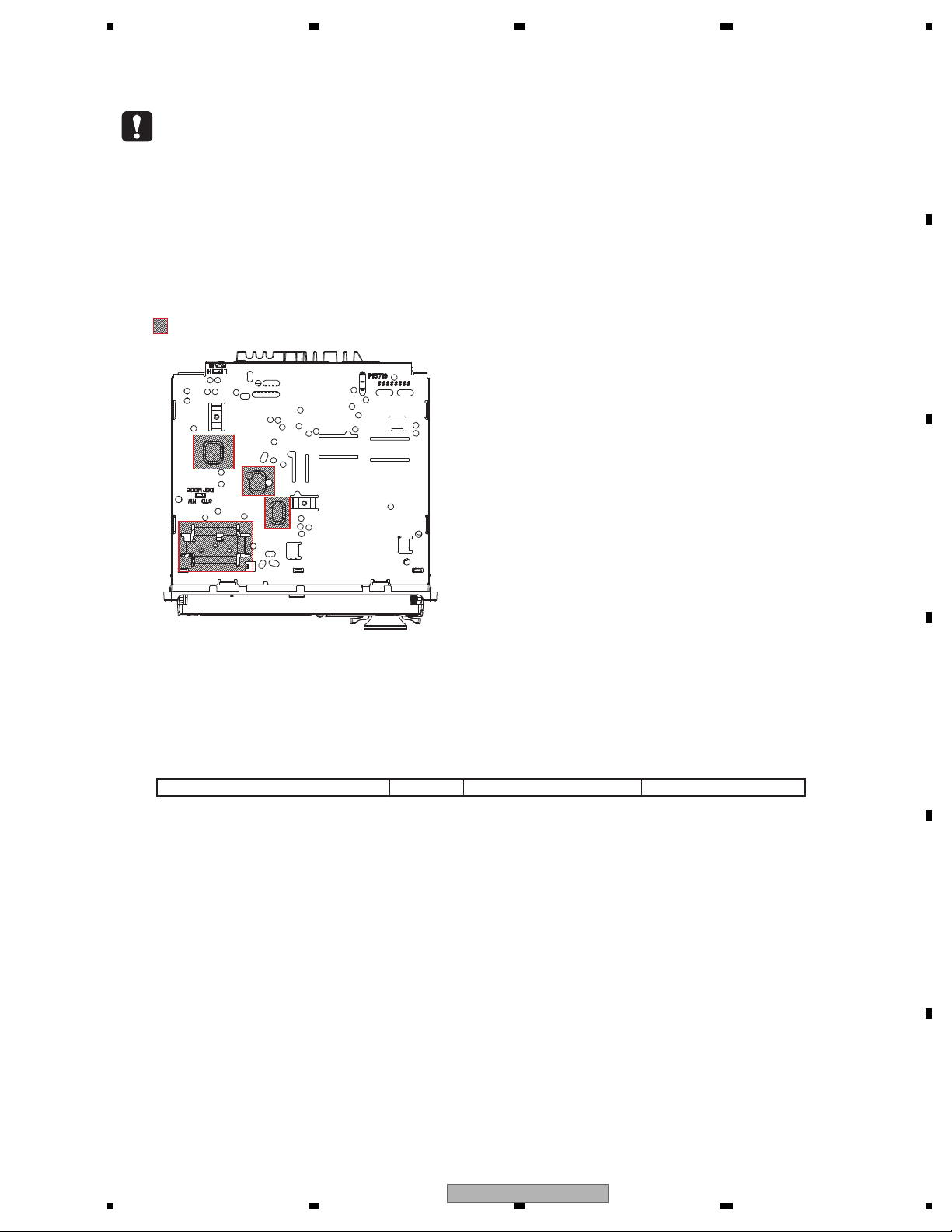
Fastening the front panel
If you do not plan to detach the front panel, the
front panel can be fastened with supplied
screws and holders.
1 Attach the holders to both sides of the
front panel.
1 Holder : CND1249, CND1250 (UC)
Holder : CXX1644, CXX1645 (EW5, ES)
2 Replace the front panel to the unit.
3 Flip the holders into upright positions.
4 Fix the front panel to the unit using fixing screws.
1 Screw : BPZ20P060FTC (UC)
Screw : XXX7020 (EW5, ES)
The Bluetooth word mark and logos are owned by the Bluetooth SIG, Inc.
and any use of such marks by Pioneer Corporation is under license.
Other trademarks and trade names are those of their respective owners.
2.2 DISC/CONTENT FORMAT
DEH-80PRS/XNUC
13
1234
1234
C
D
F
A
B
E
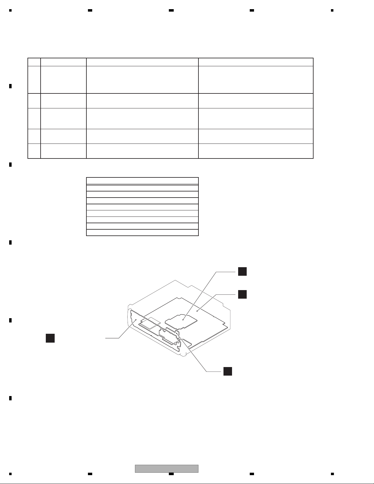
3. BASIC ITEMS FOR SERVICE
demrifnocebotmetIserudecorP.oN
1 Confirm whether the customer complain has
been solved.
If the customer complain occurs with the
specific media, use it for the operation check.
The customer complain must not be
reappeared.
Display, audio and operations must be
normal.
2 CD Play back a CD.
(Track search)
No malfunction on display, audio and
operation.
3 FM/AM tuner Check FM/AM tuner action.
(Seek, Preset)
Switch band to check both FM and AM.
Display, audio and operations must be
normal.
4 Check whether no disc is inside the product. The media used for the operating check must
be ejected.
retfaecnaraeppastinotridrosehctarcsoNkcehcecnaraeppA5
receiving it for service.
Item to be checked regarding audio
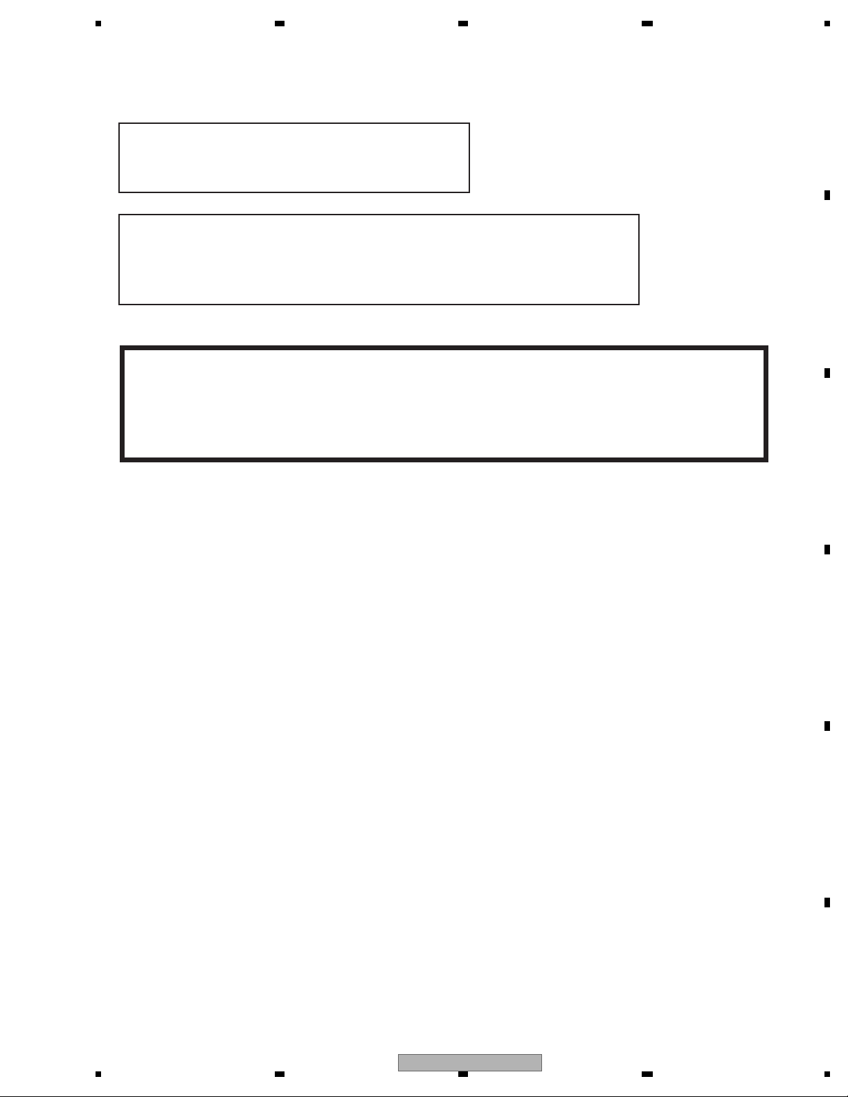
A
B
D
Keyboard Unit
Panel Unit
Tuner Amp Unit
C
CD Core Unit
(S11.6STD)
Unit Number : CWN6303(UC)
Unit Number : CWN6302(EW5)
Unit Number : CWN6304(ES)
Unit Name : Tuner Amp Unit
Unit Number : (UC,ES)
Unit Number : (EW5)
Unit Name : Keyboard Unit
Unit Number : CWX4023
Unit Name : CD Core Unit (S11.6STD)
Unit Number : CWN6306
Unit Name : Panel Unit
3.1 CHECK POINTS AFTER SERVICING
To keep the product quality after servicing, please confirm following check points.
See the table below for the items to be checked regarding audio:
Distortion
Noise
Volume too low
Volume too high
Volume fluctuating
Sound interrupted
3.2 PCB LOCATIONS
14
DEH-80PRS/XNUC
5 678
56
7
8
C
D
F
A
B
E
- Jigs List
- Grease List
Name
16P FFC
Test Disc
L.P.F.
Acetate Tape
Jig No.
GGD1310
TCD-782
GYH1026
Remarks
Tuner Amp Unit - CD Core Unit
Checking the grating
Checking the grating (Two pieces)
Capacitor Bond Lock
Name
Grease
Grease
Grease
Silicon Glue
Grease No.
GEM1024
GEM1043
GEM1013
GEM1017
Remarks
CD Mechanism Module
CD Mechanism Module
Panel Assy
Capacitor Bond Lock
N
G
Before shipping out the product, be sure to clean the
following portions by using the prescribed cleaning
tools:
Portions to be cleaned Cleaning tools
CD pickup lenses Cleaning liquid : GEM1004
Cleaning paper : GED-008
3.3 JIGS LIST
ame
3.4 CLEANING
rease No.
emarks
DEH-80PRS/XNUC
15
1234
1234
C
D
F
A
B
E
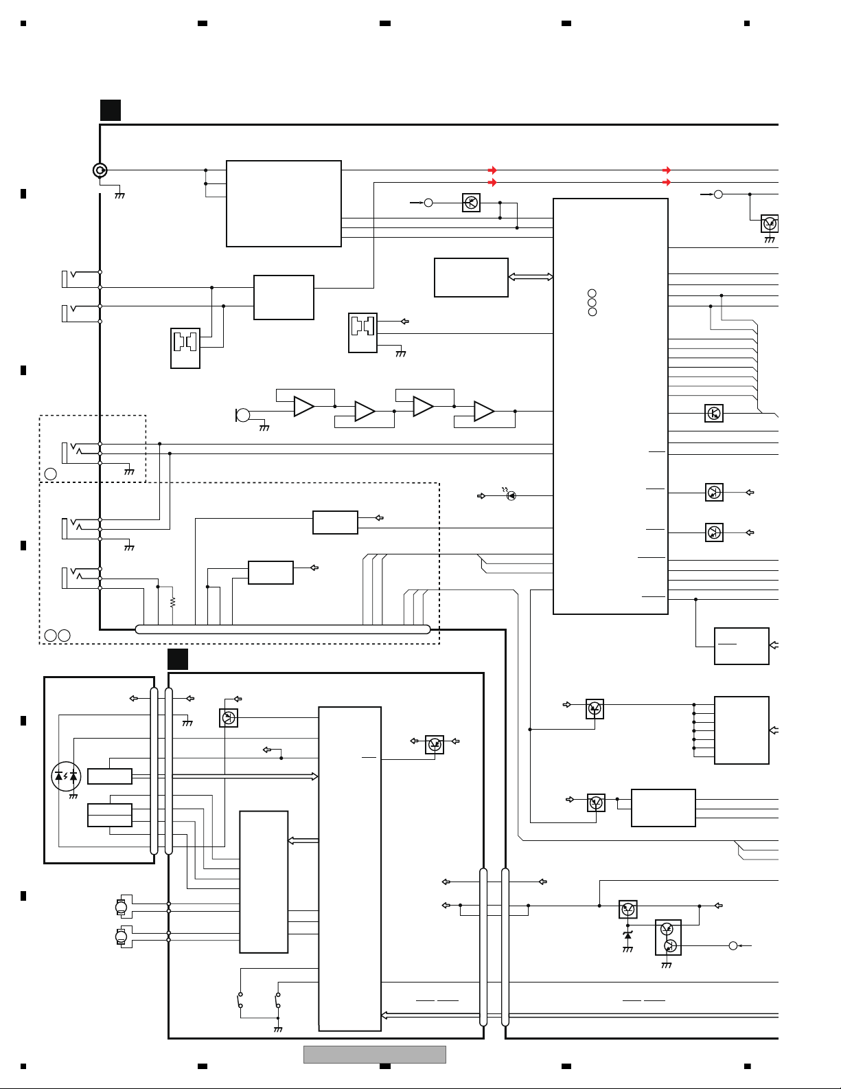
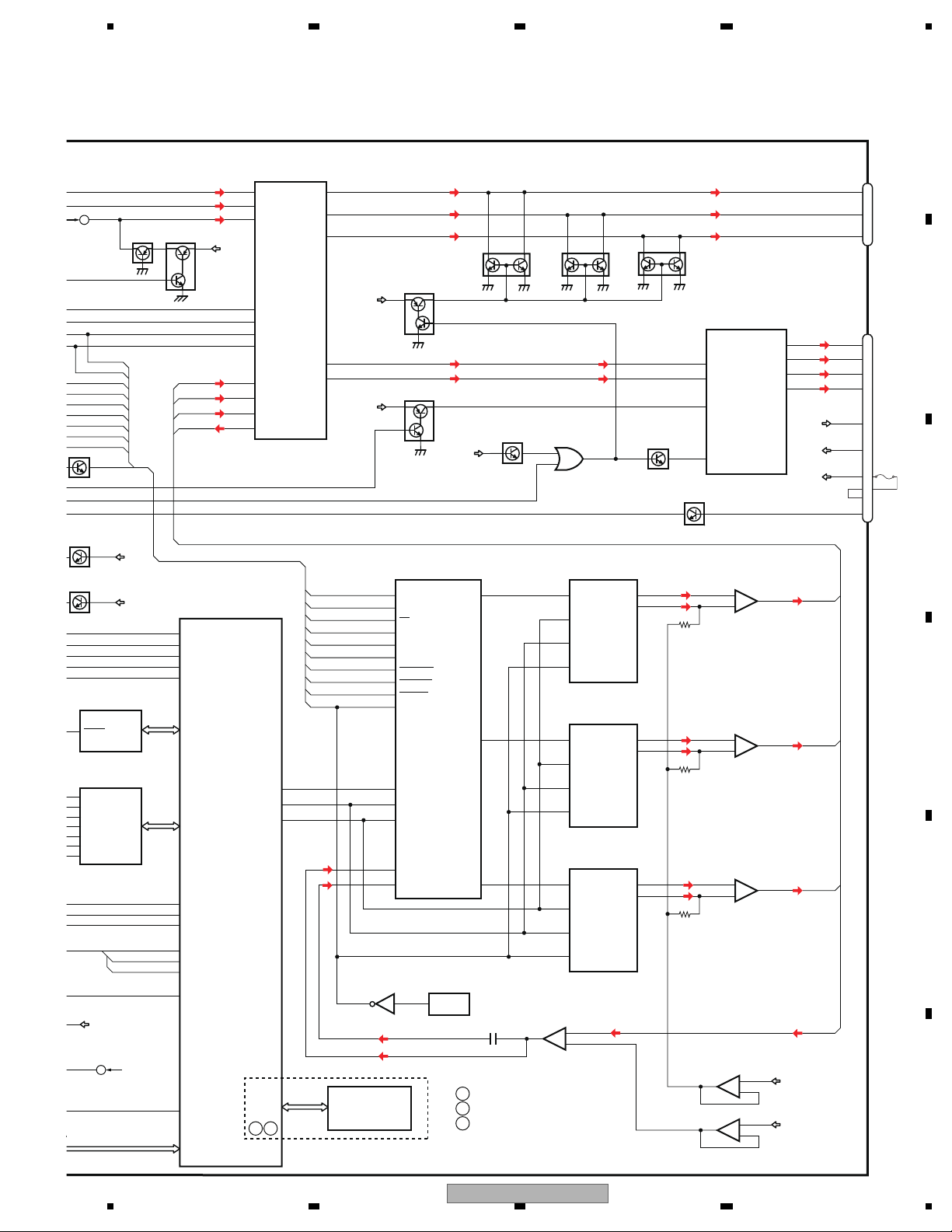
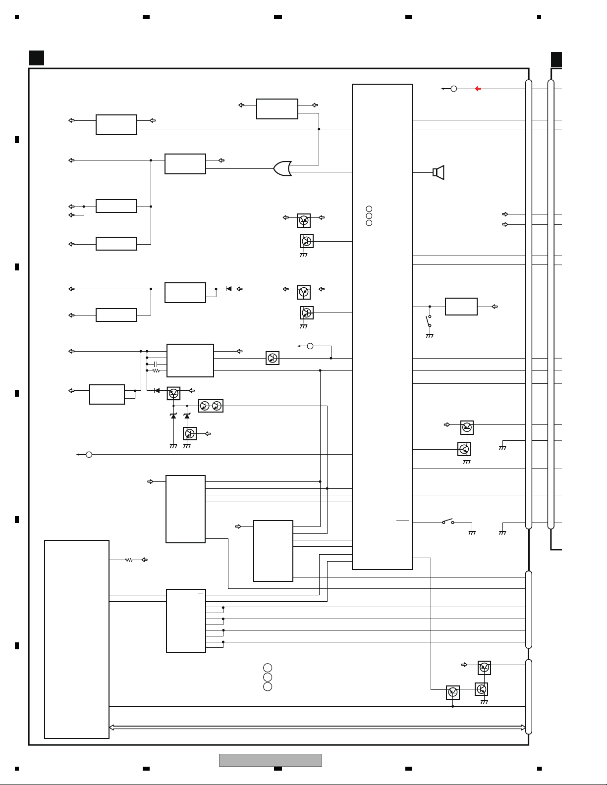
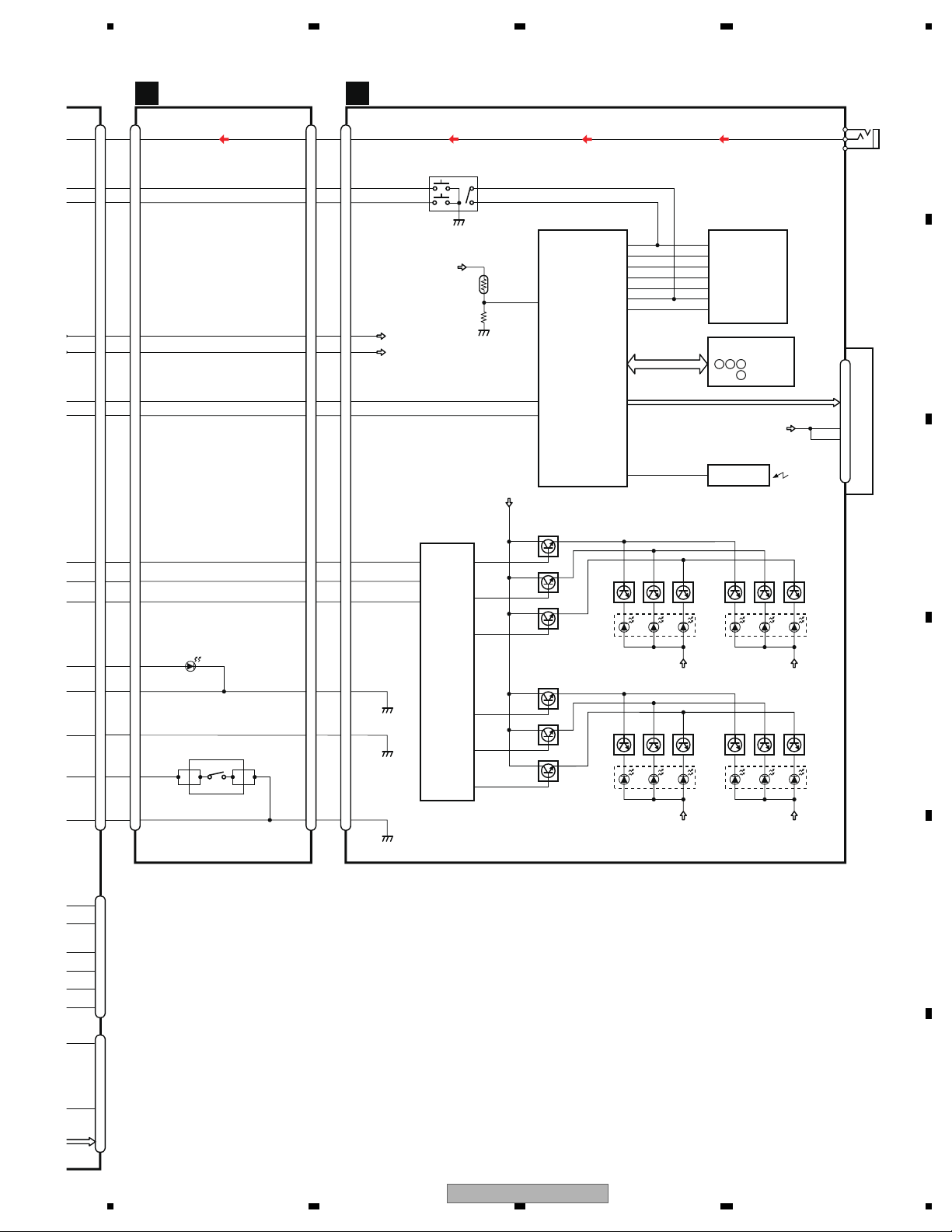
4. BLOCK DIAGRAM
TO2/2
E
TO2/2
D
DSPDRDY
DSPIN
DSPRQ
DSPCLR
DSPIRST
CKRST
DSPRST
MCKCTL
AMPPW
ASLIN
2
3
1
WIRED REMOTEBT MIC
KEYAD
KEYD
GND
5
4
JA521
6
BTMICM
BTMICP
BT33V
BT18V
BT18ON
BTTOSYS
SYSTOBT
202122
7
11
645
8
12
BTSCK
BTLRCK
131516
BT MODULE
CN521
BTRST
MEDRST
MEDSTBY
BTRX
BTPW
CPPWR
BTTX
BTRST
JA401
TUNER AMP UNIT(1/2)
2,3
1
MODESW
2
3
1
KEYAD
KEYD
GND
JA522
21OEMINRP
OEMINLM
JA351
43OEMINLP
OEMINRM
KEYAD
KEYD
92
32
100
93
22
1
20
21
VDD5V
VDD33V
VDD5V
A
FM/AM ANTENNA
SYSTEM MICRO
COMPUTER
IC601
(1/2)
ISENS
EVOLCS
50
FCKSEL
51
DSPCK
26
DSPOUT
28
AEQAUXSW
45
MUTE
48
38
8
Q481
VOUT
5
BT3.3V REG.
IC922
S-1170B33UC-OTS
4
1 68
VIN
ON/OFF
6
VINVOUT
ON/OFF
1
BT1.8V REG.
IC921
S-1172B18-E6
3
CN461
MED33V
8
9
RESET
15
16
VDD
CD DATA (CDSRQ,CDSTBY,SKIP,SCL,SDA,
DATA,BCLK,LRCK,WAIT)
CD CORE UNIT(S11.6 STD)
M
LD
MD
SPINDLE
M
LOADING/CARRIAGE
LD-
MD
15
5
HOLOGRAM
RF AMP, CD DECODER, MP3&WMA DECODER
2
VD
VD
9
3
SPO+
2
SPO-
5
SLLDO+
4
SLLDO-
22
LDIN
21
MUTE
TD,FD
AC,BD,E,F
SD,MD
LD+
14
1
LD
2
PD
CONT
LOEJ
HOME
35
41
39
VDD
1
VDD
VDD
15
5
FOCUS ACT.
TRACKING ACT.
FOP
TOP
2
1
TOP
FOP
7
TKO-
10
FCO+
2
1
14
DSCSNS
38
29
RESET
8
RESET
88
VREF
REFO
93
REFOUT
3
3
FOM
FOM
8
TKO+
4
4
TOM
TOM
9
FCO-
23
CNT
CLCONT
40
54
PUEN
V+3A
VDD
UNIT
MOTOR
MOTOR
ACTUATOR/
MOTOR DRIVER
BD8223EFV
HOMEDSCSNS
PE5791A
DIGITAL SERVO/DATA • PROCESSOR
CPU, USB HOST CONTROLLER
CN701
Q101
CN101
Q102
IC301
S901
S903
IC201
C
V+3A
12
12
VCC
PD
REFO
LD+
SOP
SOM
LCOP
LCOM
PICKUP UNIT
(P10.6)(SERVICE)
GND
CD DATA (CDSRQ,CDSTBY,SKIP,
SCL,SDA,DATA,BCLK,LRCK,WAIT)
BUP
Q881
Q882
MECHA VD
VD
BTDATA
16
Q982(1/2)
BSENS
BUP
12
4
13
2
5
I2C_SCL
nRESET
MODE1
VCC
I2C_SDA
iPod CP
IC791
341S2162
MED33V
Q791
IN1+
IC351
NJM2794RB2
DSP MODE
RCA INPUT MODE
IN1-
1
OUT1
10
9
S351
2
1
BSENS
18
Q982(2/2)
ASENS
ACC
ASENS
MEDMUTE
MEDRX
MEDTX
43
41
34
33
42
AB
C
FM/AM TUNER IC
IC401
TDA7706
5
FMMIXIN1
16
PINDIN
18
LNAIN
TUNSDA
TUNSCL
33
34
57
75
76
I2CSDA
TUNRES
31 74
RSTN
I2CSCL
DACOUTL
RESET
12
FLASH ROM
IC771
PEH322A8
EEPROM
IC661
BR25L320F-W
WIRED
REMOTE REAR AUX INPUT
BTMICM
BTMICP
MIC
_
BIAS
AUTO
S601
3
2
1
NJM4558V
ASL
1
2
3
-
+
7
5
6
-
+
IC332(1/2)
NJM4558V
IC331(1/2)
NJM4558V
IC332(2/2)
NJM4558V
IC331(2/2)
1
2
3
-
+
7
5
6
-
+
MC331
Q371
83
55
53
27
54
98
84
77
DSPtoSYS
SYStoDSP
DSPCK
MCK
TO2/2
F
SD RAM
IC751
IS42S16400F-7TL
1
VDD1
3
14
27
43
49
VDDQ1
9
VDDQ2
VDD2
VDD3
VDDQ3
VDDQ4
MED33V
Q751
:PEG866A8
:PEG865A8
A
B
:PEG864A8
C
Q601
BTSCK
BTLRCK
BTDATA
BTTOSYS
SYSTOBT
BTRST
ISOLATOR
OUT
GND
ACC
BATTERY INDICATOR
D982
MODELAD
95
F_AUXL
VDCONT
DDPWR
16
DEH-80PRS/XNUC
5 678
56
7
8
C
D
F
A
B
E
E
16
25
22
19
ANL
SWLch
RLch
FLch
9
10
20
27
28
29
43
DSPDRDY
14DSPCK
RLch
11SYStoDSP
8
5
3
1
2
5
3
1
2
5
3
1
2
DSPRQ
DSPtoSYS
DSPCLR
DSPIRST
CKRST
DSPRST
MCK
FLch
ANL
INT_RESET
CK_RESET
S_RESET
RESET
9
7
3
5
OUT1(-)
OUT1(+)
OUT2(-)
OUT2(+)
FL-
FL+
RL-
RL+
BREM
22
MUTE
13
18
17
15
ILL
7
5
1
3
CN991
IN1
11
IN2
12
STBY
4
14
11
4
2
Q304
AMP
IC271
PA2030A
JA251
Q256
45
Si4L
Si2L
11
Vi1(FL)
Vi3(RL)
Vi5(SWL)
So1L
46
44
43
CS
FCKSEL
SCK
SDA
BUP
BUP
ACC
B.REM
33
Vo5a
SWL
31
Vo3a
PRE_RL
29
Vo1a
PRE_FL
36
Vo1b
AMP_FL
38
Vo3b
AMP_RL
RCA OUTSOURCE
CONNECTOR
RL
6
FL
SWL
TUNL
6OEMINL
Si1L+
1F_AUXL
Q303
Q481
Q301
BUP
BUP
INPUT AUDIO
IC201
NJM4558V
7
6
5
+
-
BIAS BUFFER
IC241
NJM4558V
7
5
6
+
-
Q983
ISENS
MUTE
MUTE
MUTE
Q305
VDD5V
109
VDSENS
(EJSW)
BUP
A5V
1
3
2
+
-
A5V
85
BUP
CP_SCL
CP_SDA
CPRST
148
101
SO
RQ/CAD1
SDIN3/JX2
XTI
RDY
SCLK/SCL
DSP
IC101
AK7732VT
MEDIA uCOM
IC701
(1/2)
R5S7262ZD144FPU
SI/CAD0
37
SDOUT1
BCK
SCK
DATA
AUDIO DAC
IC131
PCM1793DB
LRCK
VoutL+
VoutL-
VoutL+
VoutL-
VoutL+
VoutL-
17
18
36
SDOUT2
BCK
SCK
DATA
IC132
PCM1793DB
LRCK
35
SDOUT3
BCK
SCK
OUTPUT
DATA
IC133
PCM1793DB
LRCK
AUDIO LPF
IC161
(1/2)
LT1358CS8
17
18
17
18
BSENS
ACC
ASENS
MEDIA_MUTE
SYS_TXD
BRST
SYS_RXD
59
58
63
61
SDIN5A/JX0
LRCLK_0
BITCLK_0
DACDATA
DACLRCK
DACSCK
137
138
139
22
39
38
AINL-
AINL+
63
64
43
112
CPRST
113
BT_SCKIN
111
BT_DATAIN
:DEH-80PRS/XNUC
:DEH-80PRS/XNEW5
A
B
:DEH-80PRS/XNES
C
A
B
TAGGING
IC781
A8V
Q373
RESET
12
FLASH ROM
IC771
PEH322A8
MX25L4006EM2I-12G
ELECTRONIC VOLUME/
AUTO EQ & AUX
SOURCE SELECTOR
IC211
PM9009A
Q371
DSPtoSYS
SYStoDSP
DSPCK
MCK
TO2/2
F
SD RAM
IC751
IS42S16400F-7TL
1
VDD1
3
14
27
43
49
VDDQ1
9
VDDQ2
VDD2
VDD3
VDDQ3
VDDQ4
TC7SZ04FU
IC481
X481
3
7
6
5
-
+
IC161
(2/2)
LT1358CS8
1
2
3
-
+
IC163
LT1358CS8
7
6
5
-
+
SWLch
BTSCK
BTLRCK
BTDATA
AUDIO LPF
AUDIO LPF
AUDIO DAC
AUDIO DAC
F_AUXL
4
2
Q254
Q255
VDCONT
10 A
FUSE
DEH-80PRS/XNUC
17
1234
1234
C
D
F
A
B
E
Q862
BUP
VDD5V
Q861
MED33V
Q901
Q902
Q501
VDD
CD1
SD DATA (SD_DATA0-SD_DATA3,SD_CLK,SD_CMD)
4
10
CN501
SD CARD
SD_CD
114
CN801
8
AUXL
5
CN311
USB
7
6
3
2
1
USBFLG
83
923
4
SYNC
USBOUT
VIN
FLT
USBCTL
12
5
63
USBSEL_OE
78
USBSEL
79
EN_USB
EN_SYS
IC942
OZ529IGN
MEDIA uCOM
IC701
R5S7262ZD144FPU
(2/2)
DP
DM
BUP
Q821
Q822
FLPILM
3
DPDT
20
KYDT
19
ILM+B
SW3V
13
ROT1
4
ROT0
11
RGBDT
18
RGBCK
16
RGBST
14
FLPILM
22
ILMGND
2
CSENS
9
EJECT
DGND
21
1
71
70
SYSTEM MICRO
COMPUTER
IC601
(2/2)
FLPILM
88
RGBDT
73
DPDT
29
ROT1
4
ROT0
5
KYDT
30
RGBCK
71
RGBST
72
EJECTIN
3
SDCTL
80
DSENS
17
CSENS
89
24
SYNC
87
DDPWR
19
VDCONT
44
59
USBFLG2
35
DALMON
USBCTL2
BUP
83
9
4
SYNC
USBOUT
VIN
FLT
12
5
EN_USB
EN_SYS
IC941
OZ529IGN
BUP
USB2
157
6
1
2A
4
1A
2B2
11
3
14
5
10
2
13
3B1
S
4B1
2B1
1B2
1B1
4B2
3B2
IC311
TC7MB3257FK
MULTI PLEXER
OE
S801
TUN5V
TUNER5V REG.
IC591
S-1155B50-U5
VDD5V
5
4
VINVOUT
ON/OFF
1
USB1
SD3.3V REG.
MED33V
115
SD_WP
USB5V1
USB5V2
USBDM2
USBDP2
USBDM1
USBDP1
1
MED3.3V REG.
IC912
S-1172B33-E6
6
VDD5V
MED33V
MED12V
MED1.2V REG.
IC911
S-1206B12-U3
2
VINVOUT
VINVOUT
3
3
ON/OFF
Q932
Q933
Q863
ILMPW
49
BUP
ILM+B
ILM+B
Q891
Q892
SWVDD
DSPPW
47
VDD33V
SW3V
SW3V REG.
Q854
4
6
5
3
1
Vin
SYNC
SW
2
8
BOOST
FB
BD
RUN/SS
VDD5V REG.
IC851
LT1912EMSE
BUP
B
:PEG866A8
:PEG865A8
A
:PEG864A8C
E
TO1/2
D
TO1/2
VDD5V
VDD33V
VOUT
5
VDD3.3V REG.
IC891
S-1200B33-M5
1
VIN
3
ON/OFF
SYSPW
52
A8V
36
AUDIO8V REG.
IC841
NJM2388F84
BUP
2
1
VIN
VOUT
CONTROL
4
A5V
DAC5V REG.
IC846
NJM78L05UA
3
INPUTOUTPUT
1
D3V
A3V
DSP3.3V REG.
IC831
NJM2885DL1-33
1
INOUT
3
B.REM OUT
1
B.REM
IC871
TPD1018F
5
VDD
6
IN
BUP
F
TO1/2
D
KY
ILM
DP
SW
CN
3
DG
4
19
AUX
RO
10
12
RO
15
20
RG
RG
RG
22
CS
EJE
ILM
FLA
21
14
2
5
7
9
1
TUNER AMP UNIT(2/2)
A
:DEH-80PRS/XNUC
:DEH-80PRS/XNEW5
A
B
:DEH-80PRS/XNES
C
F_AUXL
RESET
VDD33V
VDD
2
POWER ON RESET
IC651
S-80827CNMC-B8M
110
OUT
S651
2
PEE
BUZZER
BZ601
SWVDD
DSENS
VDCONT
DDPWR
RESET
18
DEH-80PRS/XNUC
5 678
56
7
8
C
D
F
A
B
E
D
:PEH368A8B
:PEH366A8AC
VDD
CD1
4
10
CN501
SD CARD
CN801
8
AUXL
5
CN311
USB
7
6
3
2
1
3
DPDT
20
KYDT
19
13
ROT1
4
ROT0
11
RGBDT
18
RGBCK
16
RGBST
14
FLPILM
22
ILMGND
2
CSENS
9
EJECT
DGND
21
1
USB5V1
USB5V2
USBDP2
USBDP1
LCD UNIT
JA1981
KEYBOARD UNIT
B
PANEL UNIT
D
AUXG
AUXL
1
3
2
KYDT
DPDT
CN1801
4
DGND
20
2
1
AUXL
7
8
11
AUXR
LCD DRIVER/
KEY CONTROLLER
IC1901
PEG870A8
ROM
IC1902
27
28
P27
P28
SWVDD
ILM+B
9
CN1951
RGBDT
RGBCK
RGBST
15
17
19
RGB DRIVER
IC1821
BH2228FV
11
12
CLK
10
CSB
DI
1
AO1
2
AO2
3
AO3
4
AO4
5
AO5
6
AO6
4
P4
IC1931
PNJ4833M
SENSOR
1
REMOTE CONTROL
ILM+B
Q1831
Q1832
Q1833
Q1861
Q1862
Q1863
BLUE
GREEN
RED
BLUE
GREEN
RED
Q1834
(2/2)
Q1834
(1/2)
Q1835
(2/2)
D1831,
D1834
ILM+B
Q1864
(2/2)
Q1864
(1/2)
Q1865
(2/2)
D1861,
D1862
ILM+B
ILM+B
Q1836
(1/2)
Q1836
(2/2)
Q1835
(1/2)
D1832,
D1833
ILM+B
Q1866
(1/2)
Q1866
(2/2)
Q1865
(1/2)
D1863,
D1864
KYDT
ILM+B
DPDT
SWVDD
CN2
3
DGND
20
4
19
AUXL
ROT1
10
12
ROT0
AUXL
ROT1
ROT0
15
20
RGBDT
RGBCK
RGBST
15
17
19
CN1
4
22
CSENS
3
CSENS
EJECT
KYDT
ILM+B
DPDT
SWVDD
DGND
ILMGND
18
ILMGND
FLAPILM
18
21
ILMGND
RGBDT
RGBCK
RGBST
CSENS
3
14
2
2
1
7
8
11
9
5
7
9
1
FRONT_AUX
ROT0
ROT1
2
1
5
4
3
ROTARY COMMANDER
S1811
2
1
4
3
S1
D1,D2
KEY MATRIX
18
P18
19
P19
20
P20
91
92
P92
NC
93
P93
95
KS2
KS1
KS0
KD3
KD2
KD1
KD0
P95
TH1901
90
P90
SWVDD
SWVDD
12
13
VDD
VDD2
SWVDD
EJECT
DEH-80PRS/XNUC
19
1234
1234
C
D
F
A
B
E
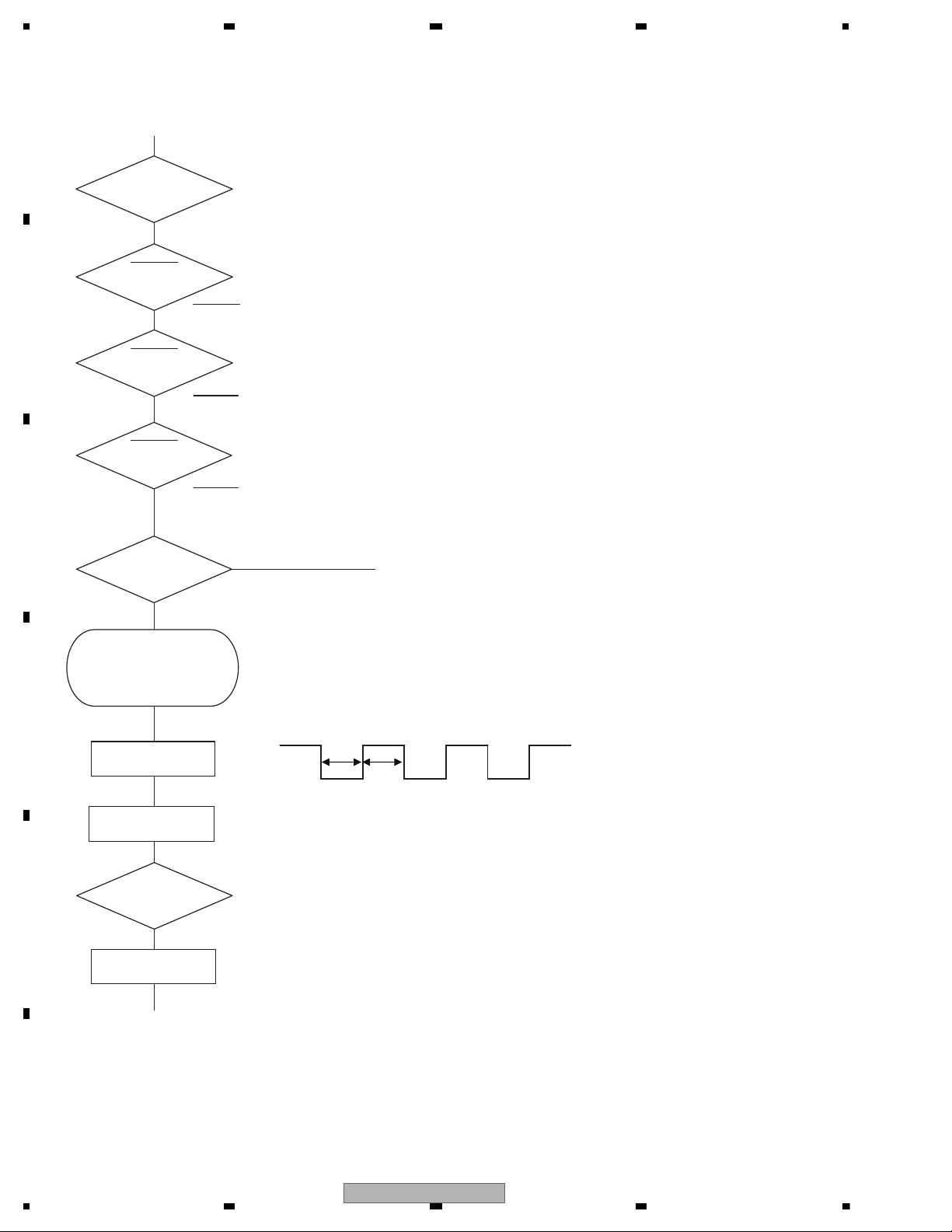
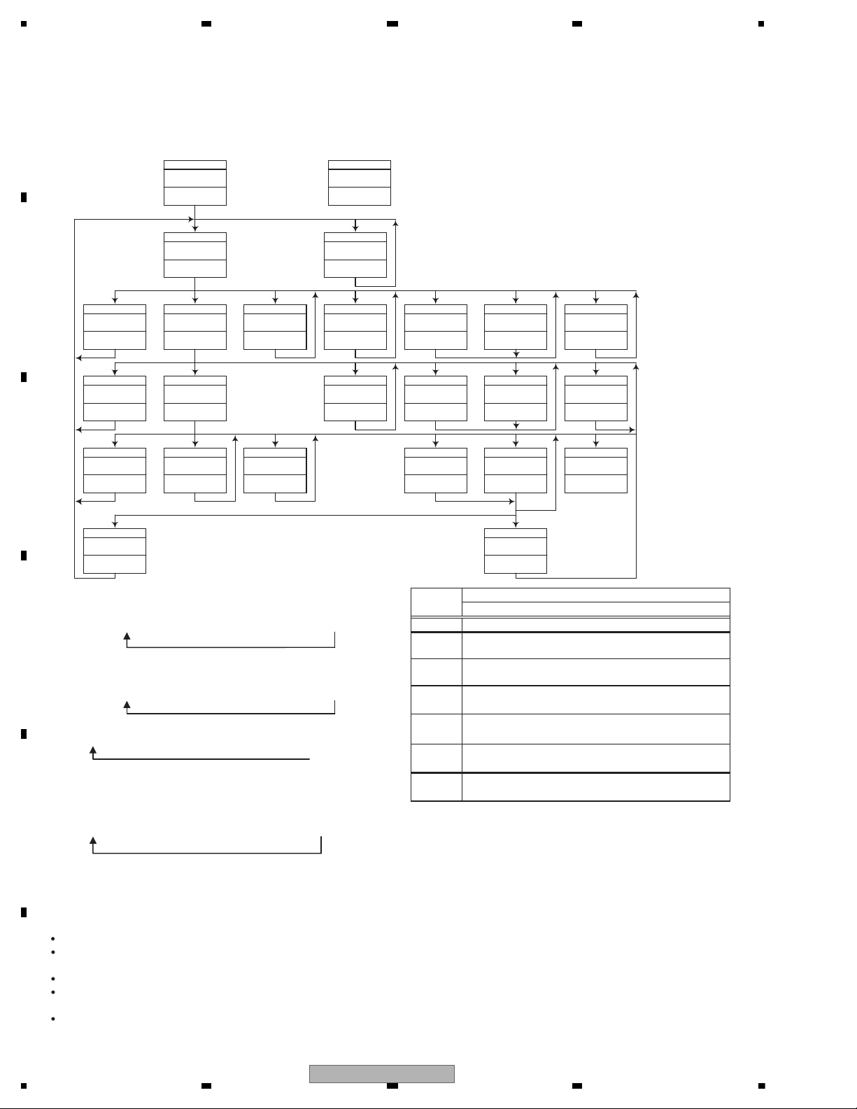
5. DIAGNOSIS
Vcc = 3.3 V
Pin 14, 60
BSENS
Pin 16
ASENS
Pin 18
DSENS
Pin 17
BSENS = L
Starts
communication
with Grille
microcomputer.
SWVDD <- H
Pin 47
Source keys
operative
Source ON
SYSPW <- H
Pin 36
Completes power-on operation.
(After that, proceed to each source operation)
500 ms
500 ms
In case of the above signal, the communication
with Grille microcomputer may fail.
If the time interval is not 500 msec, the oscillator
may be defective.
Power ON
ASENS = L
DSENS = L
CSENS
Pin 89
1.3 V < CSENS < 2 V
- 1.3 V < CSENS < 2 V
Last source returns.
CD loading functions are available.
Keys except for EJECT key are not available.
5.1 OPERATIONAL FLOWCHART
20
DEH-80PRS/XNUC
5 678
56
7
8
C
D
F
A
B
E
Error Code
The error status occurs when CD/USB/SD cannot operate, or stop during operation due to an error.
The reason for such error is displayed with a numeral.
This intends to reduce the number of nonsense calls from users and to assist in analysis/repair in services.
1. Basic display method
An error status (F0h) is entered in the Media status area of the source concerned, and the code in the minute/second area for notification.
E.g. For Read Error
Media status (disc) = 0xF0h
Minute (upper): FFh
Minute (lower): 07h
Second: 07h
- As for VD ERROR, the error status shall be 0xFB.
- Example of head unit display
The following occurs depending on the LCD display capability. The error No. comes in xx.
* For OEM, the error shall be displayed as per the specification of the OEM destination.
Display in 8 digits
Display in 6 digits
Display in 4 digits
ERROR-xx
ERR-xx
E-xx
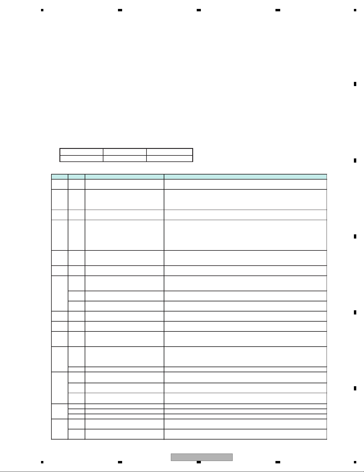
2. List of error status codes
Code Source Error status Details and reasons
07h CD Read_Error
The CD mecha cannot read the Disc TOC
The TOC section of the PRD/Disc has been damaged
10h CD
Carriage Home NG
The CRG of the CD mecha cannot move to the inner perimeter
The CRG of the CD mecha cannot move from the inner perimeter
=> Failure in the HOME SWITCH of the CD mecha. Failure in CRG movement.
Failure in communication between the microcomputer and servo LSI.
11h CD Focus_Error
(Focus Error in mechanism set up)
The CD mecha cannot take focus.
Dirt on the back of the disc and CD-RW. Significant vibration.
12h CD
Spindle Rock,
ID/SubCode Read Error/RF AMP NG
No spindle lock occurs in the CD mecha.
No sub-code can be read.
No appropriate RF AMP gain is set up.
=> Failure in the spindle. Scratches or dirt on the disc. Significant vibration.
CD-R with no written content. Occasionally the back of the disc.
CD signal abnormality.
15h CD
RF NG
Failed to read RF
-> CD-R with no written content.
CD-RW with no written content.
17h CD
Setup NG
The AGC protection does not work. Easily become out of focus.
=> Scratches or dirt on the disc. Significant vibration. CD-RW
23h CD
File Format NG
Written in the incompatible file format.
=> The CD-ROM recorded in a file format other than ISO 9660 Level 1
or 2 has been set (e.g.UDF).
USB
File Format NG
Written in the incompatible file format.
=> Recorded in a file format other than FAT 12/16/32
SD
File Format NG
Written in the incompatible file format.
=> Recorded in a file format other than FAT 12/16/32
30h CD
Search Time Out
The CD mecha could not reach the target address
=> Failure in the CRG or tracking. Scratches on the disc
50h CD
Loading_Ejecting_Mecha_Error
Disc LoadNG/EjectNG
Foreign object inserted in the mecha. Disc stuck.
16h USB
Unsuccessful authentication of iPod
Unsuccessful authentication of iPod (this occurs only with iPod)
=> In case authentication is attempted again and an error is turned back
from the iPod or authentication IC during iPod authentication
18h USB Incompatible device Incompatible device connection detected
=> In case something other than mass storage or iPod is connected
In case incompatible iPod is connected. Or in case the connected iPod
is compatible but has an incompatible firmware version.
SD Incompatible device Incompatible card connected detected (e.g. incompatible MMC) etc.
22h CD Not playable No playable file
The CD-ROM set has no MP3, WMA, AAC or WAV file.
USB Not playable No playable file
The USB device set has no MP3, WMA, AAC or WAV file.
SD Not playable No playable file
The SD card set has not MP3, WMA, AAC or WAV file.
24h CD All DRM All playable files in the disc are DRM.
USB All DRM All playable files in the device are DRM.
SD All DRM All playable files in the SD card are DRM.
19h USB
Communication error
Cannot communicate with the device
=> In case the device failure or other reason prevents communication
SD
Communication error
Cannot communicate with the SD card
=> In case the SD card failure or other reason prevents communication
5.2 ERROR CODE LIST
DEH-80PRS/XNUC
21

1234
1234
C
D
F
A
B
E
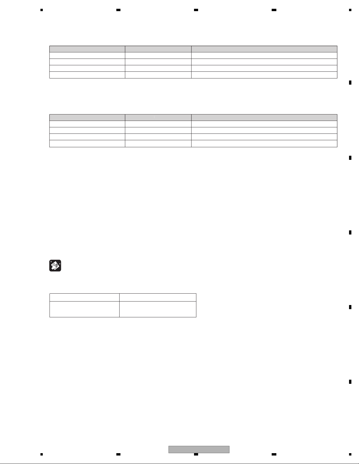
External storage device (USB, SD)/iPod
Message Cause Action
NO DEVICE No USB storage
device or iPod is
connected.
Connect a compatible USB storage
device/iPod.
FORMAT
READ
Sometimes there
is a delay between the start of
playback and
when you start to
hear any sound.
Wait until the message disappears
and you hear
sound.
NO AUDIO There are no
songs.
Transfer the audio
files to the USB
storage device and
connect.
The connected
USB storage device has security
enabled.
Follow the USB
storage device instructions to disable the security.
SKIPPED The connected
USB storage device contains
files embedded
with Windows
Media™ DRM 9/
10.
Play an audio file
not embedded with
Windows Media
DRM 9/10.
PROTECT All the files in the
USB storage device are embedded with
Windows Media
DRM 9/10.
Transfer audio files
not embedded with
Windows Media
DRM 9/10 to the
USB storage device and connect.
NOT COMPATIBLE
The USB device
connected to is
not supported by
this unit.
Connect a USB
Mass Storage
Class compliant
device.
Disconnect your
device and replace
it with a compatible USB storage
device.
Non-compatible
iPod
Disconnect your
device and replace
it with a compatible iPod.
Non-compatible
SD storage device
Remove your device and replace it
with a compatible
SD storage device.
Message Cause Action
CHECK USB The USB connec-
tor or USB cable
has shortcircuited.
Check that the
USB connector or
USB cable is not
caught in something or damaged.
The connected
USB storage device consumes
more than maximum allowable
current.
Disconnect the
USB storage device and do not
use it. Turn the
ignition switch to
OFF, then to ACC
or ON and then
connect only compliant USB storage
devices.
The iPod operates correctly but
does not charge.
Make sure the connection cable for
the iPod has not
shorted out (e.g.,
not caught in
metal objects).
After checking,
turn the ignition
switch OFF and
back ON, or disconnect the iPod
and reconnect.
ERROR-19 Communication
failed.
Perform one of
the following operations.
–Turn the ignition
switch OFF and
back ON.
–Disconnect or
eject the external
storage device.
–Change to a different source.
Then, return to the
USB or SD source.
Disconnect the
cable from the
iPod. Once the
iPod’s main menu
is displayed, reconnect the iPod and
reset it.
iPod failure. Disconnect the
cable from the
iPod. Once the
iPod’s main menu
is displayed, reconnect the iPod and
reset it.
22
DEH-80PRS/XNUC

5 678
56
7
8
C
D
F
A
B
E
Message Cause Action
ERROR-23 USB storage de-
vice was not formatted with
FAT12, FAT16 or
FAT32.
USB storage device should be formatted with FAT12,
FAT16 or FAT32.
ERROR-16 The iPod firm-
ware version is
old.
Update the iPod
version.
iPod failure. Disconnect the
cable from the
iPod. Once the
iPod’s main menu
is displayed, reconnect the iPod and
reset it.
STOP There are no
songs in the current list.
Select a list that
contains songs.
Not found No related
songs.
Transfer songs to
the iPod.
Bluetooth device
Message Cause Action
ERROR-10 The power failed
for the Bluetooth
module of this
unit.
Turn the ignition
switch OFF and
then to ACC or ON.
If the error message is still displayed after
performing the
above action,
please contact
your dealer or an
authorized Pioneer
Service Station.
Pandora
Message Cause Action
ERROR-19 Communication
failed.
Disconnect the
cable from the
iPod. Once the
iPod’s main menu
is displayed, reconnect the iPod and
reset it.
Start up the
Pandora Application
The Pandora application has not
started running
yet.
Start up the
Pandora application from your
iPod/iPhone.
Message Cause Action
Try again later Unable to save
thumb rating.
Unable to save
BookMark.
Pandora system
is undergoing
maintenance.
Try again later.
Skip limit
reached
Skip limit
reached.
Do not exceed the
skip limit.
Check Application
This version of
the Pandora application is not
supported.
Connect an iPod/
iPhone that has a
compatible version
of the Pandora application installed.
Check Device Device error mes-
sage displayed in
Pandora Application.
Unable to play
music from
Pandora.
Please check your
iPod/iPhone.
No Available
Station
No station found. Create a station in
the Pandora application on your
iPod/iPhone.
No Active Stations
No station selected.
Select a station.
Auto TA and EQ
Message Cause Action
ERR:MIC check The microphone
is not connected.
Plug the supplied
microphone securely into the
jack.
ERR:Front
Speaker,ERR:
Front-Lch,
ERR:Front-Rch,
ERR:Rear-Lch,
ERR:Rear-Rch,
ERR:SubWLch,ERR:
SubW-Rch,
ERR:SubWoofer
The microphone
cannot pick up
the measuring
tone of a speaker.
Confirm that the
speakers are connected correctly.
Cancel muting
the front speaker
units.
Correct the input
level setting of the
power amp connected to the
speakers.
Set the microphone correctly.
ERR:Outside
Noise
The surrounding
noise level is too
high.
Stop your car in
a place that is
quiet, and switch
off the engine, air
conditioner and
heater.
Set the microphone correctly.
DEH-80PRS/XNUC
23
1234
1234
C
D
F
A
B
E
5.3 CONNECTOR FUNCTION DESCRIPTION
1 FL+
2 FR+
3 FL4 FR5 RL+
6 RR+
7 RL8 RR-
9 NC
10 NC
11 ILL
12 NC
13 ACC
14 B.REM
15 B.UP
16 GND
16
14
12
10 8
6
42
15
13
11
97
5
31
FM/AM ANTENNA
USB
REAR OUTPUT or
HIGH RANGE OUTPUT
SUBWOOFER or
LOW RANGE OUTPUT
REAR AUX
INPUT
FRONT OUTPUT or MID RAGE OUTPUT
WIRED REMOTE CONTROL INPUT
MICROPHONE INPUT for BT
(UC, EW5 only)
24
DEH-80PRS/XNUC
5 678
56
7
8
C
D
F
A
B
E
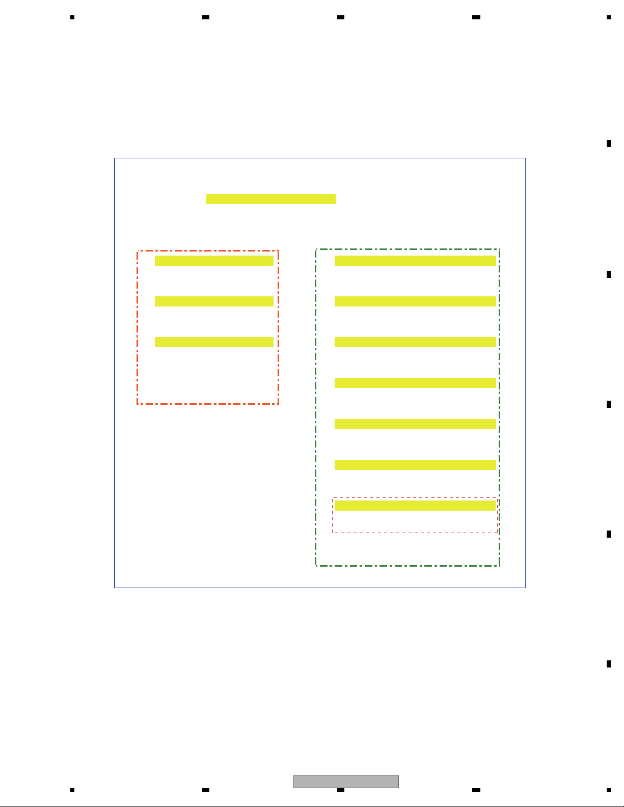
Service Display Test Mode
2. Operation method
u
u
rrr Display test mode selection screen tt
uu
u EQ+BAND key u LIST key
uu
uu
t General display of display mode t Display of version information
iu iu
iu
EQ + BAND key
iuLIST key
iu iu
i Static display of display mode i Display of ROM collection information
iu iu
iu
EQ + BAND key
iuLIST key
iu iu
i All lights ON i All lights ON
iu iu
iu
EQ + BAND key
iuLIST key
iu iu
rru i All lights OFF
iu
iuLIST key
iu
i Confirmation of image ROM connection
iu
iuLIST key
iu
i Display of media microcomputer information
iu
iuLIST key
iu
i Display of Manufacture_ID information
iu
iuLIST key UC only
iu
rru
<Display Test Mode> <Service display Test Mode>
1. Overview
This is the test mode which summarized the confirmation of the system microcomputer version and
the all light ON/OFF functions of a display part.
Turn on BUP and ACC while pressing [EQ] + [BAND] together.
6. SERVICE MODE
6.1 DISPLAY TEST MODE
DEH-80PRS/XNUC
25
1234
1234
C
D
F
A
B
E
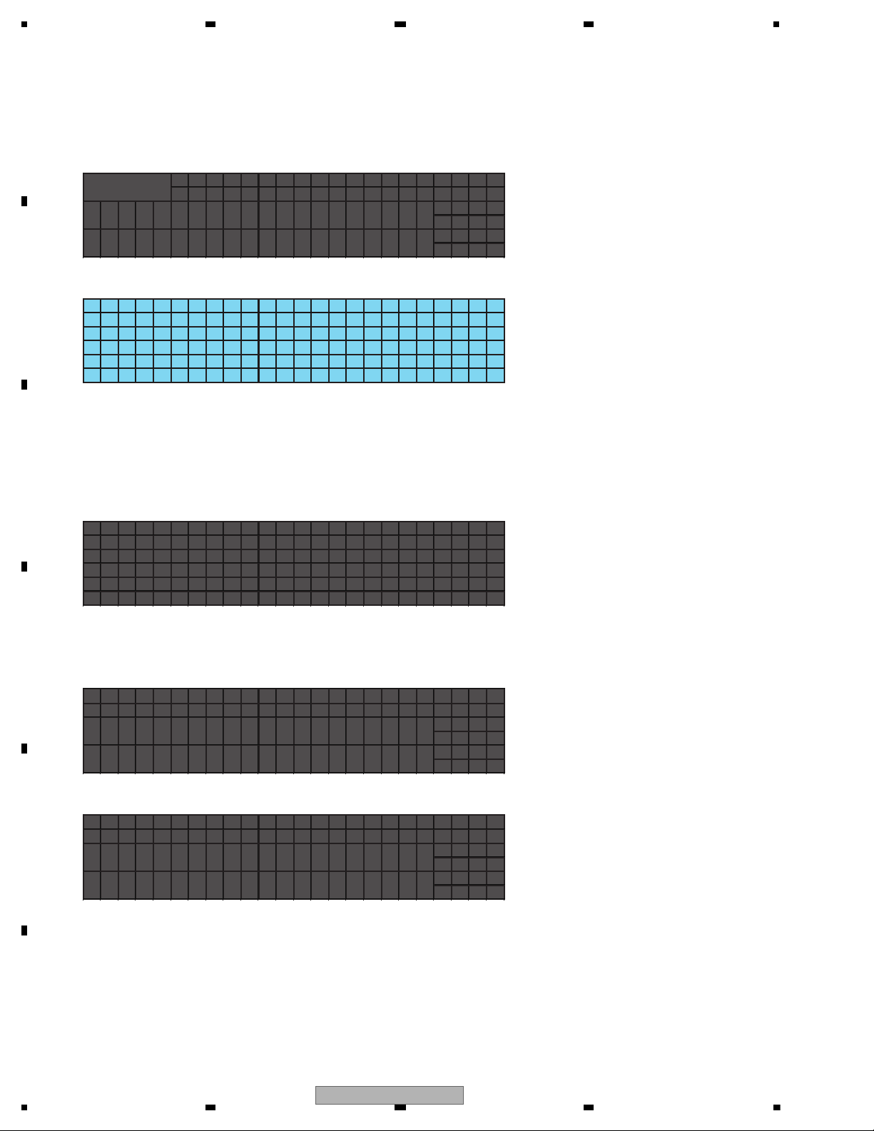
3. Contents to be displayed
Display test mode selection screen
Manual Flap model
0 8 16 24 32 40 48 56 64 72 80 88 96 04 12 20 28 36 44 52 60 68 76 84 92
8
-Mode Select-
16
24
32
40
48
All lights ON
0 8 16 24 32 40 48 56 64 72 80 88 96 04 12 20 28 36 44 52 60 68 76 84 92
8
16
24
32
40
48
- If nothing appears on the screen:
There might be a problem in communication or abnormality in the display microcomputer.
- If noise appears on the screen:
There might be abnormality in the display microcomputer or a problem, for instance, in connection between the
display microcomputer and the OEL driver.
Display of version information
0 8 16 24 32 40 48 56 64 72 80 88 96 04 12 20 28 36 44 52 60
68 76 84 92
Description:
8
IC Info.
UNIT
16
--------------------
24
PD Ve r UNI T
32
SYS ***** *.** _ ????
40
DI S ##### # . ## _ &&&&
48
PIC !!!!! !.!!
????:The unit number information of the system
microcomputer
&&&&:The unit number information of the display
microcomputer
Display the four-digit number only.
(For CWW1969, display 1969)
Display of ROM collection information
(1) If no information could be acquired from EEPROM
0 8 16 24 32 40 48 56 64 72 80 88 96 04 12 20 28 36 44 52 60
68 76 84 92
8
EEPROM I n f o .
16
--------------------
24
$$$$$$$$$$$:Error information
32
When ROM collection is not connected:
NO_EEPROM
40
ROM collection data error:ROM_ERROR
48
(2) If information is successfully acquired from EEPROM
0 8 16 24 32 40 48 56 64 72 80 88 96 04 12 20 28 36 44 52 60
68 76 84 92
8
EEPROM I n f o .
16
--------------------
24
####:EEPROM collection version information
32
! ! ! !:CH use information
40
(1: Used, 0: Not used. Corresponding to:
CH1, CH2, CH3 and CH4 from left)
48
- If nothing appears on the screen:
There might be a problem in communication or abnormality in the display microcomputer.
- If an obviously weird numeral appears as the version:
There might be a problem in communication.
- If the number of CHs used is not properly displayed despite the version displayed:
There might be defective connection with EEPROM.
!!####- ! !SYSTEM :
###- !!!!
$$$$
PLA$Y: #
$
DIS
SYSTEM $
$$$$$$$$$
$$:
LAY
PL Y :ADIS
TEST
DISP BAND
VI
Q+
CE
:E
SER : L I ST
26
DEH-80PRS/XNUC

5 678
56
7
8
C
D
F
A
B
E
All lights OFF
0 8 16 24 32 40 48 56 64 72 80 88 96 04 12 20 28 36 44 52 60 68 76 84 92
8
16
24
32
40
48
- If noise appears on the screen:
There might be abnormality in the display microcomputer or a problem, for instance, in connection between the
display microcomputer and the OEL driver.
Confirmation of image ROM connection
0 8 16 24 32 40 48 56 64 72 80 88 96 04 12 20 28 36 44 52 60 68 76 84 92
8
Bus Connect T e s t
16
--------------------
24
32
40
48
##:OK or NG
- If nothing appears on the screen:
There might be a problem in communication or abnormality in the display microcomputer.
- If NG appears somewhere:
There might be defective connection between the display microcomputer and image ROM.
For instance, NG appearing with respect to the data bus does not necessarily mean data bus connection is definitely
defective.
Where the address bus is the reason for NG appearing, an error could still occur when checking the data bus.
Display of media microcomputer information
0 8 16 24 32 40 48 56 64 72 80 88 96 04 12 20 28 36 44 52 60 68 76 84 92
Description:
8
MED I A I n f o .
UNIT
16
--------------------
24
PD * * * * *
_:
Caution: The display is blank because nothing is sent
from the media microcomputer.
32
UN I T
_ ????
????:Media microcomputer unit number information
40
Ver * * . * *
48
- If nothing appears on the screen:
There might be a problem in communication to the display microcomputer, or abnormality in the display
microcomputer itself.
- If an obviously weird numeral appears on the media microcomputer version:
There might be a problem in communication between the system microcomputer and display microcomputer, or
between the system and media microcomputer.
Display of Manufacture_ID information (UC only)
0 8 16 24 32 40 48 56 64 72 80 88 96 04 12 20 28 36 44 52 60 68 76 84 92
8
Ma n u f a c t u r e I D
16
--------------------
24
0xC02820ED
32
40
48
ADRS #:#
us :
Bus
##DATA B
DEH-80PRS/XNUC
27
1234
1234
C
D
F
A
B
E
6.2 CD TEST MODE
[Key]
Contents
Display
[BAND]
Power On
(T.Offset is adjusted)
TRK MIN SEC
00 00 00
[2]
RF AMP
Gain switching
GG GG GG
*1
[3]
Focus Close
S curve check
TRK MIN SEC
91 91 91
[6]
Focus Mode switching
0X 0X 0X
*2
[1]
Tracking Servo
Close
00 00 00
or 99 99 99
[UP]
CRG +
[2]
Self-adjusting
switching
TRK MIN SEC
?? ?? ??
*3*6
[DOWN]
CRG -
*6
[BAND]
Power Off
TRK MIN SEC
[BAND]
Power Off
TRK MIN SEC
[BAND]
Power Off
TRK MIN SEC
[BAND]
Power Off
TRK MIN SEC
[1]
T.Close & AGC
Applicable servomechanism
TRK MIN SEC
?tr ?min ?sec
[3]
RF AGC /
RF AGC coefficient display
[UP]
CRG +
8X 8X 8X
or 9X 9X 9X
[2]
T.Balance adjustment /
T.BAL coefficient display
TRK MIN SEC
?? ?? ??
[DOWN]
CRG -
?? ?? ??
[1]
F,T,RF AGC
F.Bias display switching
TRK MIN SEC
TRK MIN SEC
TRK MIN SEC
[3] [UP]
CRG/TR Jump +
[2]
Tracking Open
[DOWN]
CRG/TR Jump -
?tr ?min ?sec
TRK MIN SEC
TRK MIN SEC
00 00 00
or 99 99 99
TRK MIN SEC
?tr ?min ?sec
8X 8X 8X
or 9X 9X 9X
8X 8X 8X
or 9X 9X 9X
00 00 00
or 99 99 99
TRK MIN SEC
?tr ?min ?sec?? ?? ??
*5
F,T AGC / F.Bias
RF AGC
8X 8X 8X
or 9X 9X 9X
[2]
Tracking Open
*6
*4 *4
Operation
[Key]
Test Mode
[BAND] Power On/Off
[UP]
CRG + / TR Jump +
(Direction of the external surface)
[DOWN]
CRG - / TR Jump (Direction of the internal surface)
[1] T. CLS & AGC & Applicable servomechanism /
AGC,AGC display setting
[2] RF Gain switching / Offset adjustment display /
T.Balance adjustment / T. Open
[3] F. Close,S. Curve / Rough Servo and RF AGC /
F,T,RF AGC
[6] F. Mode switching / Tracking Close
After the [EJECT] key is pressed keys other than the [EJECT] key should not be pressed, until disc ejection is complete.
When the key [UP] or [DOWN] is pressed during the Focus Search, the power supply should be immediately turned off (otherwise the
lens sticks to Wall, causing the actuator to be damaged).
In the case of 100TR Jump, the mechanism shall be set to the Tracking Close mode when the key is released.
When the power is turned on/off the gain of the RFAMP is reset to 0 dB. At the same time all the self-adjusting values shall return to the
default setting.
Do not do Tracking Servo Close before doing Focus Servo Close. (Because the overcurrent flows)
- Flow Chart
[CD] or [SOURCE]
Source ON
TRK MIN
To enter the test mode: [PHONE] + [BAND] -> BUP + ACC ON (UC, EW5)
[COLOR] + [BAND] -> BUP + ACC ON (ES)
Operate with a Remote Control with 1 - 6 keys for a CD Receiver in the test mode.
*1) TYP t + 6 dB t + 12 dB
TRK
MIN
SEC
TRK06MIN06SEC
06
TRK12MIN12SEC
12
*2) Focus Close
t S. Curve t F EQ measurement setting
TRK00MIN00SEC
00
TRK
01
MIN01SEC
01
TRK02MIN02SEC
02
(
TRK99MIN99SEC
99)
*3) F.Offset Display t
*4) 100TR Jump
*5) TRK/MIN/SEC
t F.AGC t T.AGC Gain t F.Bias t RF AGC
*6) CRG motor voltage = 2 [V]
RF.Offset
Switch to the order
of the original
display
t
T.Offset Display t
28
DEH-80PRS/XNUC
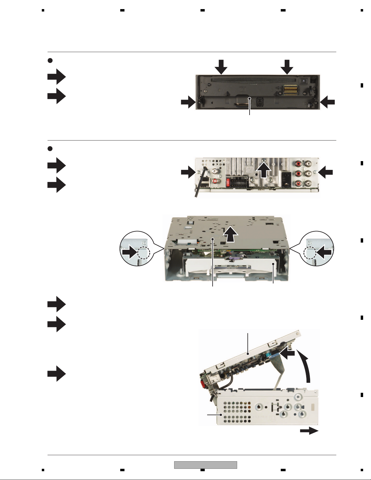
5 678
56
7
8
C
D
F
A
B
E
2
1
2
1
1
2
1
2
3
4
5
1
Push the area and remove the two hooks.
Slide the Tuner Amp Assy in the direction
of the arrow.
Disconnect the FFC and then remove the
CD Mechanism Module.
2 2
3
3
5
Lift off the Tuner Amp Assy from the Front Side.
Front
Heat Sink Side
The CD Mechanism Module side is made a bottom.
- Removing the CD Mechanism Module (Fig.2, 3, 4)
CD Mechanism Module
CD Mechanism Module
Tuner Amp Assy
Remove the two screws.
Release the two latches and then remove
the Panel Assy.
- Removing the Panel Assy (Fig.1)
Fig.4
Fig.1
Fig.2
Fig.3
Remove the screw.
Remove the two screws.
Panel Assy
Tuner Amp Assy
4
7. DISASSEMBLY
DEH-80PRS/XNUC
29
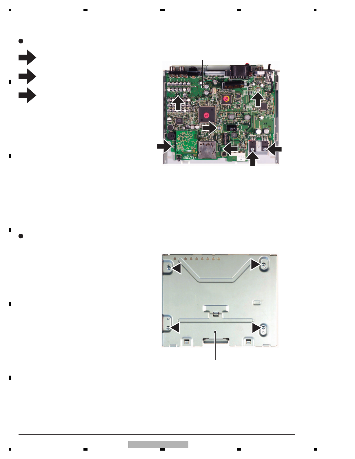
1234
1234
C
D
F
A
B
E
1
2
3
- Removing the Tu n er Amp Unit (Fig.5)
Remove the two screws.
Remove the two screws.
Straighten the tabs at three locations
indicated and then remove the Tu n e r
Amp Unit.
Tu n e r Amp Unit
CD Mechanism Module
- Attention of removing (Fig.6)
Don’t remove this screws excluding the dismantlement
of the CD Mechanism Module.
Fig.5
Fig.6
3
1
3
2
3
1
2
30
DEH-80PRS/XNUC
 Loading...