

Pioneer DEH-80PRS Installation Manual

CD RDS RECEIVER
AUTORADIO CD RDS
REPRODUCTOR DE CD CON RECEPTOR RDS
DEH-80PRS
English EspañolFrançais
Installation Manual
Manuel d’installation
Manual de instalación
i
Section
01
Connections
Connections
WARNING
! Use speakers over 50 W (output value) and
between 4 W to 8 W (impedance value). Do
not use 1 W to 3 W speakers for this unit.
! The black cable is ground. When installing
this unit or power amp (sold separately),
make sure to connect the ground wire first.
Ensure that the ground wire is properly connected to metal parts of the car’s body. The
ground wire of the power amp and the one of
this unit or any other device must be connected to the car separately with different
screws. If the screw for the ground wire loosens or falls out, it could result in fire, generation of smoke or malfunction.
Ground wire
Other devices
(Another electronic
device in the car)
POWER AMP
Metal parts of car’s body
Important
! When installing this unit in a vehicle without
an ACC (accessory) position on the ignition
switch, failure to connect the red cable to the
terminal that detects operation of the ignition
key may result in battery drain.
O
F
N
F
O
S
T
A
R
T
ACC position No ACC position
! Use this unit with a 12-volt battery and nega-
tive grounding only. Failure to doso mayresult in a fire or malfunction.
! To prevent a short-circuit, overheatingor mal-
function, be sure to follow the directions
below.
— Disconnect the negative terminal ofthe bat-
tery before installation.
— Secure the wiring with cable clamps or adhe-
sive tape. Wrap adhesive tape around wiring
that comes into contact with metal parts to
protect the wiring.
— Place all cables away from moving parts,
such as the shift lever and seat rails.
— Place all cables away from hot places, such
as near the heater outlet.
— Do not connect the yellow cable to the battery
by passing it through the hole to the engine
compartment.
— Cover any disconnected cable connectors
with insulating tape.
— Do not shorten any cables.
— Never cut the insulation of the power cable of
this unit in order to share the power with
other devices. The current capacity of the
cable is limited.
— Use a fuse of the rating prescribed.
— Never wire the negative speaker cable directly
to ground.
— Never band together negative cables of multi-
ple speakers.
! When this unit is on, control signals are sent
through the blue/white cable. Connect this
cable to the system remote control of an external power amp or the vehicle’s auto-antenna relay control terminal (max. 300 mA
12 V DC). If the vehicle is equipped with a
glass antenna, connect it to the antenna
booster power supply terminal.
! Never connect the blue/white cable to the
power terminal of an external power amp.
Also, never connect it to the power terminal
of the auto antenna. Doing so may result in
battery drain or a malfunction.
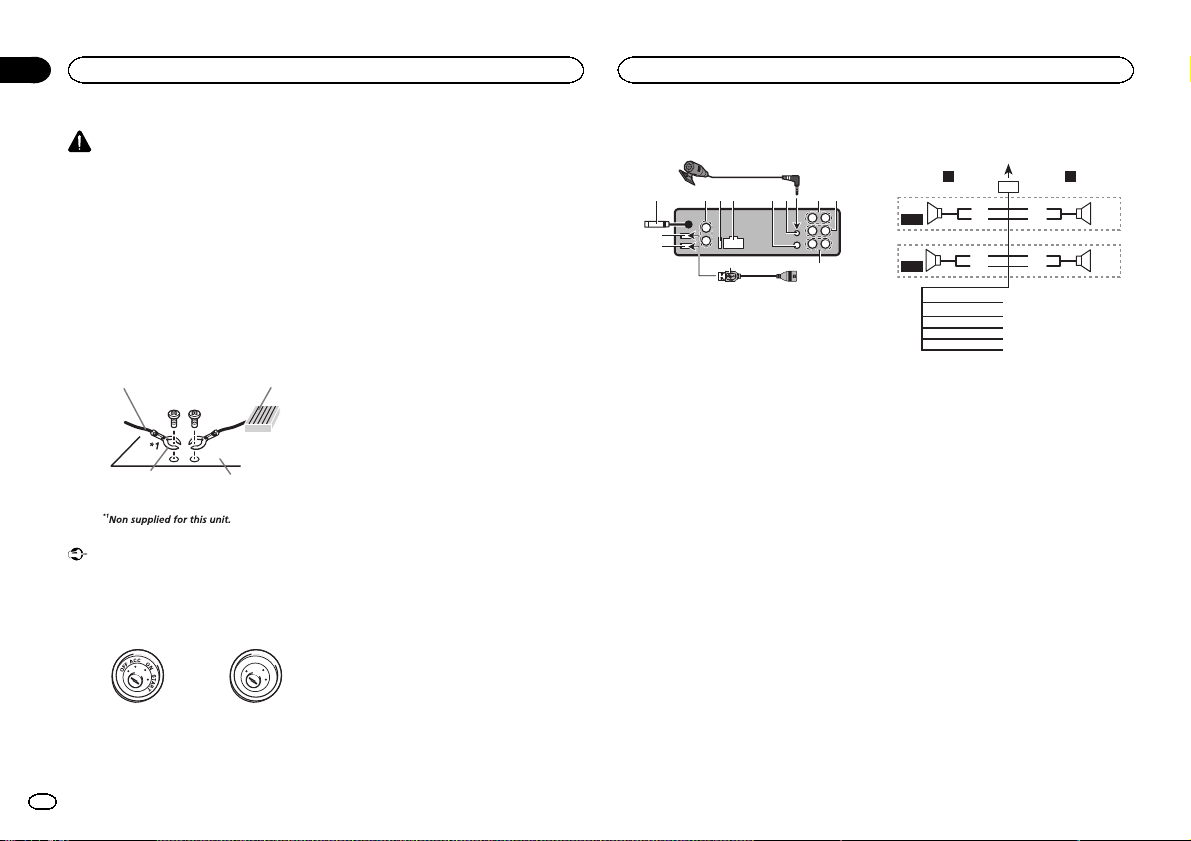
This unit
9
4
3
2
1
1 USB port 1
2 USB port 2
3 Antenna input
15 cm (5-7/8 in.)
4 Audio input
5 Fuse (10 A)
6 Power cord input
7 Wired remote input
Hard-wired remote control adaptor can be
connected (sold separately).
8 Microphone input
9 Microphone
4 m (13 ft. 1 in.)
a Rear output or high range output
b Front output or middle range output
c Subwoofer output or low range output
d USB cable
1.5 m (4 ft. 11 in.)
! If connecting both USB1 (USB storage
device1)/iPod1 (iPod connected using
USB input1) and USB2 (USB storage device2)/iPod2 (iPod connected using USB
input2) at the same time, use a Pioneer
USB cable (CD-U50E) in addition to the
regular Pioneer USB cable.
5 6a7 b
8
d
c
Power cord
LR
4
F/M
5
R/H
1 To power cord input
2 Left
3 Right
4 Front speaker or middle range speaker
5 Rear speaker or high range speaker
6 White
7 White/black
8 Gray
9 Gray/black
a Green
b Green/black
c Violet
d Violet/black
e Black (chassis ground)
Connect to a clean, paint-free metal location.
f Yellow
Connect to the constant 12 V supply terminal.
g Red
Connect to terminal controlled by ignition
switch (12 V DC).
h Blue/white
Connect to system control terminal of the
power amp or auto-antenna relay control terminal (max. 300 mA 12 V DC).
i Orange/white
Connect to lighting switch terminal.
1
32
8
6
9
7
a
b
e
f
g
h
c
d
2
En
Connections
Connections
Section
01
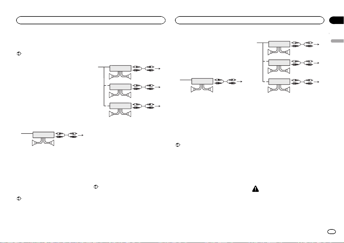
Power amp (sold separately)
Standard mode with internal amp
Important
! Change the DSP switch to standard mode
(STD).
For more details on change settings, refer to
the operation manual or Switching the DSP
setting mode on this page.
! The following signals are output from the
speaker leads when this connection is in
use.
White: Front left +
White/black: Front left *
Gray: Front right +
Gray/black: Front right *
Green: Rear left +
Green/black: Rear left *
Violet: Rear right +
Violet/black: Rear right *
1
1 System remote control
Connect to Blue/white cable.
2 Power amp (sold separately)
3 Connect with RCA cable (sold separately)
4 To subwoofer output
5 Subwoofer
Standard mode without internal
amp
Important
! Change the DSP switch to standard mode
(STD).
For more details on change settings, refer to
the operation manual or Switching the DSP
setting mode on this page.
3
2
55
4
! If using this system, we recommend that this
unit’s internal amp is turned off.
For details, refer to the operation manual.
! The speaker leads are not used when this
connection is in use.
1
1
1
1 System remote control
Connect to Blue/white cable.
2 Power amp (sold separately)
3 Connect with RCA cable (sold separately)
4 To Rear output
5 Rear speaker
6 To Front output
7 Front speaker
8 To subwoofer output
9 Subwoofer
3
2
55
3
2
77
3
2
99
4
6
8
3-way network mode with
internal amp
Important
! Change the DSP switch to 3-way network
mode (NW).
For more details on change settings, refer to
the operation manual or Switching the DSP
setting mode on this page.
! The following signals are output from the
speaker leads when this connection is in
use.
White: Middle range left +
White/black: Middle range left *
Gray: Middle range right +
Gray/black: Middle range right *
Green: High range left +
Green/black: High range left *
Violet: High range right +
Violet/black: High range right *
1
1 System remote control
Connect to Blue/white cable.
2 Power amp (sold separately)
3 Connect with RCA cable (sold separately)
4 To low range output
5 Low range speaker
3
2
55
4
3-way network mode without
internal amp
Important
! Change the DSP switch to 3-way network
mode (NW).
For more details on change settings, refer to
the operation manual or Switching the DSP
setting mode on this page.
! If using this system, we recommend that this
unit’s internal amp is turned off.
For details, refer to the operation manual.
! The speaker leads are not used when this
connection is in use.
1
1
1
1 System remote control
Connect to Blue/white cable.
2 Power amp (sold separately)
3 Connect with RCA cable (sold separately)
4 To high range output
5 High range speaker
6 To middle range output
7 Middle range speaker
8 To low range output
9 Low range speaker
3
2
55
3
2
77
3
2
99
4
6
8
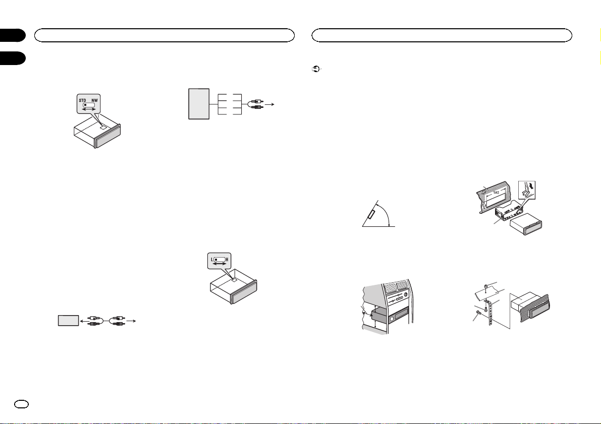
Switching the DSP setting mode
This unit features two operation modes: the 3way network mode (NW) and the standard mode
(STD). You can switch between modes as desired. Initially, the DSP setting is set to the
standard mode (STD).
! After switching, reset the microprocessor.
WARNING
Do not use the unit in standard mode when a
speaker system for 3-way network mode is connected to this unit. This may cause damage to
the speakers.
English
3
En
5cmcm
Section
Connections
01
02
1 Use a thin, flathead screwdriver to
change the DSP switch on the bottom of this
unit.
2 Press RESET with a pen tip or other
pointed instrument.
For details, refer to the operation manual.
Audio input
If you connect the unit to an audio device with
RCA output, or to one with no RCA output, you
can set it up so that the audio from the audio device is output through speakers connected to
the unit. Change settings as necessary based on
whether the connected device has RCA output
or not.
For more details on change settings, refer to the
operation manual or Switching between RCA
input modes on this page.
If connecting the unit to a car
stereo with RCA output
23 4
1
1 Car stereo with RCA output
2 To audio output
3 Connect with RCA cable (sold separately)
4 To audio input
If connecting the unit to a car
stereo with no RCA output
3
7
1
1 Car stereo with no RCA output
2 To speaker output
3 Red: Right +
4 Black: Right *
5 Black: Left *
6 White: Left +
7 Speaker-RCA conversion cable (supplied)
19 cm (7-1/2 in.)
8 To audio input
5
6
4
2
8
Switching between RCA input
modes
% Use a thin, flathead screwdriver to
change the RCA input mode switch on the
bottom of this unit.
! L (Low) - If inputting from the RCA output of a
connected device
! H (High) - If inputting from the speaker out-
put of a connected device
Installation
Important
! Check all connections and systems before
final installation.
! Do not use unauthorized parts as this may
cause malfunctions.
! Consult your dealer if installation requires
drilling of holes or other modifications to the
vehicle.
! Do not install this unit where:
— it may interfere with operation of the vehicle.
— it may cause injury to a passenger as a result
of a sudden stop.
! The semiconductor laser will be damaged if
it overheats. Install this unit away from hot
places such as near the heater outlet.
! Optimum performance is obtained when the
unit is installed at an angle of less than 60°.
60°
! When installing, to ensure proper heat dis-
persal when using this unit, make sure you
leave ample space behind the rear panel and
wrap any loose cables so they are not blocking the vents.
Leave ample
space
5 cm
5 cm
DIN front/rear mount
This unit can be properly installed using either
front-mount or rear-mount installation.
Use commercially available parts when installing.
DIN Front-mount
1 Insert the mounting sleeve into the dashboard.
For installation in shallow spaces, use the supplied mounting sleeve. If there is enough space,
use the mounting sleeve that came with the vehicle.
2 Secure the mounting sleeve by using a
screwdriver to bend the metal tabs (90°) into
place.
1
2
1 Dashboard
2 Mounting sleeve
3 Install the unit as illustrated.
1
2
4
5
1 Nut
2 Firewall or metal support
3 Metal strap
4 Screw
5 Screw (M4 × 8)
3
4
En
Installation
Installation
Section
02
# Make sure that the unit is installed securely in
place. An unstable installation may cause skipping
or other malfunctions.
DIN Rear-mount
1 Determine the appropriate position
where the holes on the bracket and the side
of the unit match.
2 Tighten two screws on each side.
1
2
1 Screw
2 Mounting bracket
3 Dashboard or console
! Use either truss (5 mm × 8 mm) or flush sur-
face (5 mm × 9 mm) screws, depending on
the bracket screw holes.
3
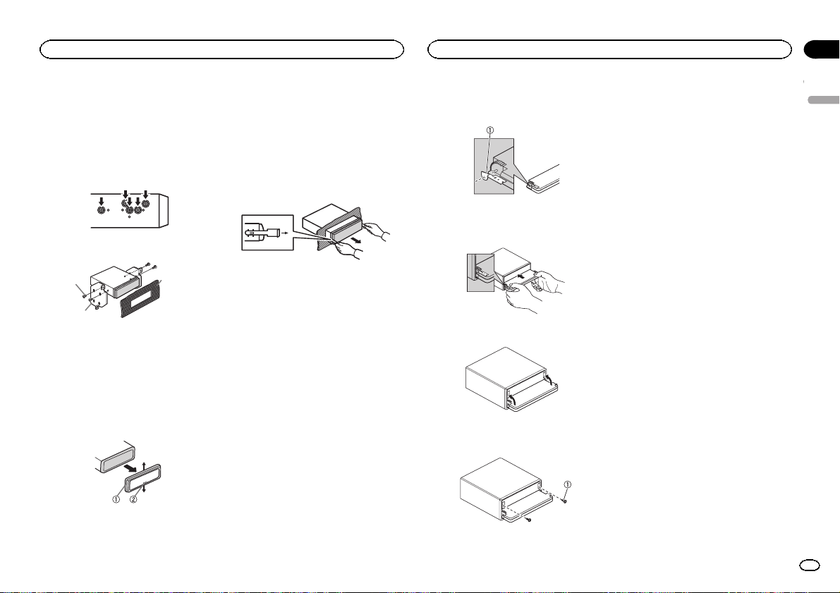
Removing the unit
1 Remove the trim ring.
! Releasing the front panel allows easier ac-
cess to the trim ring.
! When reattaching the trim ring, point the
side with the notched tab down.
2 Insert the supplied extraction keys into
both sides of the unit until they click into
place.
3 Pull the unit out of the dashboard.
Removing and re-attaching
the front panel
You can remove the front panel to protect your
unit from theft.
Press the detach button and push the front
panel upward and pull it toward you.
For details, refer to operation manual.
Fastening the front panel
If you do not plan to detach the front panel, the
front panel can be fastened with supplied
screws and holders.
1 Attach the holders to both sides of the
front panel.
1 Holder
2 Replace the front panel to the unit.
3 Flip the holders into upright positions.
4 Fix the front panel to the unit using fixing screws.
English
1 Trim ring
2 Notched tab
1 Screw
5
En
4
2
Section
Installing the microphone
03
Installing the microphone
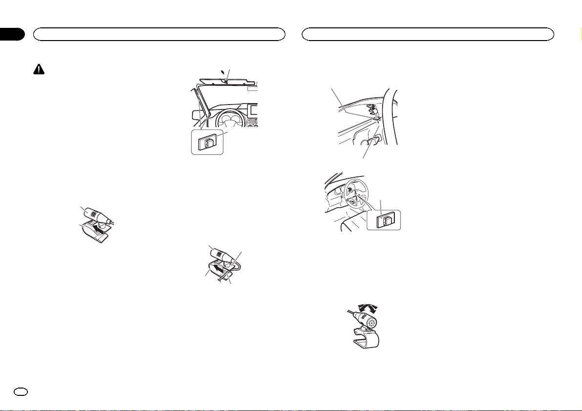
CAUTION
It is extremely dangerous to allow the microphone lead to become wound around the steering column or shift lever. Be sure to install the
unit in such a way that it will not obstruct driving.
Note
Install the microphone in a position and orientation that will enable it to pick up the voice of the
person operating the system.
When installing the
microphone on the sun visor
1 Install the microphone on the microphone clip.
1
2
1 Microphone
2 Microphone clip
2 Install the microphone clip on the sun
visor.
With the sun visor up, install the microphone
clip. (Lowering the sun visor reduces the voice
recognition rate.)
1
2
1 Microphone clip
2 Clamp
When installing the
microphone on the steering
column
1 Install the microphone on the microphone clip.
1
3
1 Microphone
2 Microphone base
3 Microphone clip
4 Fit the microphone lead into the groove.
# Microphone can be installed without using microphone clip. In this case, detach the microphone
base from the microphone clip. To detach the microphone base from the microphone clip, slide the microphone base.
2
2 Install the microphone clip on the steering column.
1
3
1 Double-sided tape
2 Install the microphone clip on the rear side of
the steering column.
3 Clamp
Adjusting the microphone
angle
The microphone angle can be adjusted.
6
En
 Loading...