


Pioneer DEH-6300SD, DEH-6390SD Service manual
PIONEER CORPORATION 1-1, Shin-ogura, Saiwai-ku, Kawasaki-shi, Kanagawa 212-0031, Japan
PIONEER ELECTRONICS (USA) INC. P.O. Box 1760, Long Beach, CA 90801-1760, U.S.A.
PIONEER EUROPE NV Haven 1087, Keetberglaan 1, 9120 Melsele, Belgium
PIONEER ELECTRONICS ASIACENTRE PTE. LTD. 253 Alexandra Road, #04-01, Singapore 159936
PIONEER CORPORATION 2010
CD RDS RECEIVER
ORDER NO.
CRT4672
DEH-6300SD/XNEW5
DEH-6300SD
/XNEW5
DEH-6350SD/XNES
DEH-6350SD/XNES1
DEH-6390SD/XNID
This service manual should be used together with the following manual(s):
Model No. Order No. Mech. Module Remarks
CX-3269 CRT4488 S11.1STD-DOUT CD Mech. Module : Circuit Descriptions, Mech. Descriptions, Disassembly
For details, refer to "Important Check Points for Good Servicing".
K-ZZZ DEC. 2010 Printed in Japan
1234
1234
C
D
F
A
B
E
SAFETY INFORMATION
Where in a manufacturer’s service documentation, for example in circuit diagrams or lists
of components, a symbol is used to indicate that a specific component shall be replaced only
by the component specified in that documentation for safety reasons, the following symbol shall
be used:
This service manual is intended for qualified service technicians; it is not meant for the casual do-it-yourselfer.
Qualified technicians have the necessary test equipment and tools, and have been trained to properly and safely repair
complex products such as those covered by this manual.
Improperly performed repairs can adversely affect the safety and reliability of the product and may void the warranty.
If you are not qualified to perform the repair of this product properly and safely, you should not risk trying to do so
and refer the repair to a qualified service technician.
CAUTION:
USE OF CONTROLS OR ADJUSTMENTS OR PERFORMANCE OF PROCEDURES OTHER THAN THOSE
SPECIFIED HEREIN MAY RESULT IN HAZARDOUS RADIATION EXPOSURE.
WARNING!
The AEL (accessible emission level )of the laser power output is less than CLASS 1
but the laser component is capable of emitting radiation exceeding the limit for
CLASS 1.
A specially instructed person should do servicing operation of the apparatus.
Laser diode characteristics
Wave length : 785 nm to 814 nm
Maximum output : 1 190 µW(Emitting period : unlimited)
Additional Laser Caution
Transistors Q101 in PCB drive the laser diodes.
When Q101 is shorted between their terminals, the laser diodes will radiate beam.
If the top cover is removed with no disc loaded while such short-circuit is continued,
the naked eyes may be exposed to the laser beam.
- Safety Precautions for those who Service this Unit.
When checking or adjusting the emitting power of the laser diode exercise caution in order to get safe, reliable
results.
Caution:
1. During repair or tests, minimum distance of 13 cm from the focus lens must be kept.
2. During repair or tests, do not view laser beam for 10 seconds or longer.
CAUTION
This product is a class 1 laser product classified under the Safety of laser products, IEC
60825-1:2007, and contains a class 1M laser
module. To ensure continued safety, do not remove any covers or attempt to gain access to
the inside of the product. Refer all servicing to
qualified personnel.
CAUTION—CLASS 1M INVISIBLE LASER
RADIATION WHEN OPEN, DO NOT VIEW
DIRECTLY WITH OPTICAL INSTRUMENTS.
2
DEH-6300SD/XNEW5

5 678
56
7
8
C
D
F
A
B
E
CAUTION
Danger of explosion if battery is incorrectly replaced.
Replaced only with the same or equivalent type recommended by the manufacture.
Discord used batteries according to the manufacture's instructions.
DEH-6300SD/XNEW5
3
1234
1234
C
D
F
A
B
E
[Important Check Points for Good Servicing]
In this manual, procedures that must be performed during repairs are marked with the below symbol.
Please be sure to confirm and follow these procedures.
1. Product safety
Please conform to product regulations (such as safety and radiation regulations), and maintain a safe servicing environment by
following the safety instructions described in this manual.
1 Use specified parts for repair.
Use genuine parts. Be sure to use important parts for safety.
2 Do not perform modifications without proper instructions.
Please follow the specified safety methods when modification(addition/change of parts) is required due to interferences such as
radio/TV interference and foreign noise.
3 Make sure the soldering of repaired locations is properly performed.
When you solder while repairing, please be sure that there are no cold solder and other debris.
Soldering should be finished with the proper quantity. (Refer to the example)
4 Make sure the screws are tightly fastened.
Please be sure that all screws are fastened, and that there are no loose screws.
5 Make sure each connectors are correctly inserted.
Please be sure that all connectors are inserted, and that there are no imperfect insertion.
6 Make sure the wiring cables are set to their original state.
Please replace the wiring and cables to the original state after repairs.
In addition, be sure that there are no pinched wires, etc.
7 Make sure screws and soldering scraps do not remain inside the product.
Please check that neither solder debris nor screws remain inside the product.
8 There should be no semi-broken wires, scratches, melting, etc. on the coating of the power cord.
Damaged power cords may lead to fire accidents, so please be sure that there are no damages.
If you find a damaged power cord, please exchange it with a suitable one.
9 There should be no spark traces or similar marks on the power plug.
When spark traces or similar marks are found on the power supply plug, please check the connection and advise on secure
connections and suitable usage. Please exchange the power cord if necessary.
a Safe environment should be secured during servicing.
When you perform repairs, please pay attention to static electricity, furniture, household articles, etc. in order to prevent injuries.
Please pay attention to your surroundings and repair safely.
2. Adjustments
To keep the original performance of the products, optimum adjustments and confirmation of characteristics within specification.
Adjustments should be performed in accordance with the procedures/instructions described in this manual.
4. Cleaning
For parts that require cleaning, such as optical pickups, tape deck heads, lenses and mirrors used in projection monitors, proper
cleaning should be performed to restore their performances.
3. Lubricants, Glues, and Replacement parts
Use grease and adhesives that are equal to the specified substance.
Make sure the proper amount is applied.
5. Shipping mode and Shipping screws
To protect products from damages or failures during transit, the shipping mode should be set or the shipping screws should be
installed before shipment. Please be sure to follow this method especially if it is specified in this manual.
4
DEH-6300SD/XNEW5

5 678
56
7
8
C
D
F
A
B
E
CONTENTS
SAFETY INFORMATION .....................................................................................................................................2
1. SERVICE PRECAUTIONS................................................................................................................................6
1.1 SERVICE PRECAUTIONS .........................................................................................................................6
1.2 NOTES ON SOLDERING...........................................................................................................................7
2. SPECIFICATIONS.............................................................................................................................................8
2.1 SPECIFICATIONS ......................................................................................................................................8
2.2 DISC/CONTENT FORMAT .........................................................................................................................9
2.3 PANEL FACILITIES...................................................................................................................................10
2.4 CONNECTION DIAGRAM........................................................................................................................12
3. BASIC ITEMS FOR SERVICE........................................................................................................................14
3.1 CHECK POINTS AFTER SERVICING .....................................................................................................14
3.2 PCB LOCATIONS .....................................................................................................................................14
3.3 JIGS LIST .................................................................................................................................................15
3.4 CLEANING ...............................................................................................................................................15
4. BLOCK DIAGRAM ..........................................................................................................................................16
4.1 BLOCK DIAGRAM....................................................................................................................................16
5. DIAGNOSIS ....................................................................................................................................................19
5.1 OPERATIONAL FLOWCHART.................................................................................................................19
5.2 ERROR CODE LIST.................................................................................................................................20
5.3 CONNECTOR FUNCTION DESCRIPTION .............................................................................................22
6. SERVICE MODE.............................................................................................................................................23
6.1 DISPLAY TEST MODE .............................................................................................................................23
6.2 CD TEST MODE.......................................................................................................................................24
7. DISASSEMBLY ...............................................................................................................................................25
8. EACH SETTING AND ADJUSTMENT............................................................................................................31
8.1 CD ADJUSTMENT ...................................................................................................................................31
8.2 CHECKING THE GRATING AFTER CHANGING THE PICKUP UNIT ....................................................32
8.3 PCL OUTPUT CONFIRMATION...............................................................................................................34
9. EXPLODED VIEWS AND PARTS LIST ..........................................................................................................36
9.1 PACKING ..................................................................................................................................................36
9.2 EXTERIOR ...............................................................................................................................................38
9.3 CD MECHANISM MODULE .....................................................................................................................40
10. SCHEMATIC DIAGRAM................................................................................................................................42
10.1 TUNER AMP UNIT (1/2) (GUIDE PAGE) ...............................................................................................42
10.2 TUNER AMP UNIT (2/2) (GUIDE PAGE) ...............................................................................................48
10.3 KEYBOARD UNIT ..................................................................................................................................54
10.4 CD CORE UNIT (S11.1STD-DOUT) ......................................................................................................56
10.5 SD UNIT .................................................................................................................................................58
10.6 WAVEFORMS.........................................................................................................................................59
11. PCB CONNECTION DIAGRAM....................................................................................................................62
11.1 TUNER AMP UNIT .................................................................................................................................62
11.2 KEYBOARD UNIT ..................................................................................................................................66
11.3 CD CORE UNIT (S11.1STD-DOUT) ......................................................................................................68
11.4 SD UNIT .................................................................................................................................................70
12. ELECTRICAL PARTS LIST ...........................................................................................................................71
DEH-6300SD/XNEW5
5
1234
1234
C
D
F
A
B
E
1. SERVICE PRECAUTIONS
1. You should conform to the regulations governing the product (safety, radio and noise, and other
regulations), and should keep the safety during servicing by following the safety instructions
described in this manual.
2. Before disassembling the unit, be sure to turn off the power. Unplugging and plugging the connectors
during power-on mode may damage the ICs inside the unit.
3. To protect the pickup unit from electrostatic discharge during servicing, take an appropriate treatment
(shorting-solder) by referring to "the DISASSEMBLY".
4. After replacing the pickup unit, be sure to check the grating.
5. Be careful in handling ICs. Some ICs such as MOS type are so fragile that they can be damaged by
electrostatic induction.
6. area and a heat sink becomes hot areas. Be careful not to burn yourself.
7. Notes on replacing parts
The part listed below is difficult to replace as a discrete component part.
ASSY NAME Ref No. Part No. Remarks
Tuner Amp Unit IC601 PEG640A8 Narrow pitch
IC401 TDA7706 Narrow pitch
IC501 R5S7262ZD144FPU Narrow pitch
IC571 CWW2867 Narrow pitch
8. How to Handle Infrared Detecting unit for Remote Control of Grille
The infrared detecting unit for remote control of keyboard unit is not fixed with cushion, etc.
When external force is applied on the infrared detecting unit for remote control, the light receiving sensitivity might be
deteriorated since the lead bents and attaching angle of the light receiving part may be varied.
Please do not apply external force onto the infrared detecting unit for remote control. If any external force is applied by
mistake, please confirm whether lead bending may exist or not.
If the lead is bent, please correct the angle between the lead and the light receiving part to be 90 degrees or replace
the infrared detecting unit for remote control (GP1UXC14RK).
1.1 SERVICE PRECAUTIONS
6
DEH-6300SD/XNEW5
5 678
56
7
8
C
D
F
A
B
E
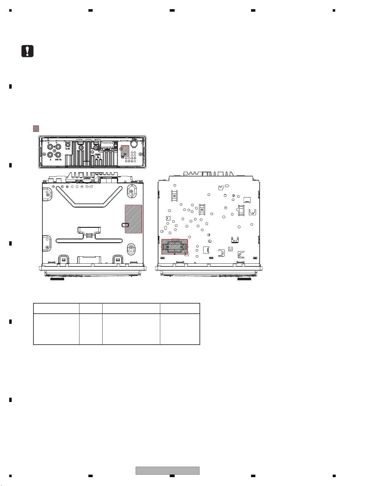
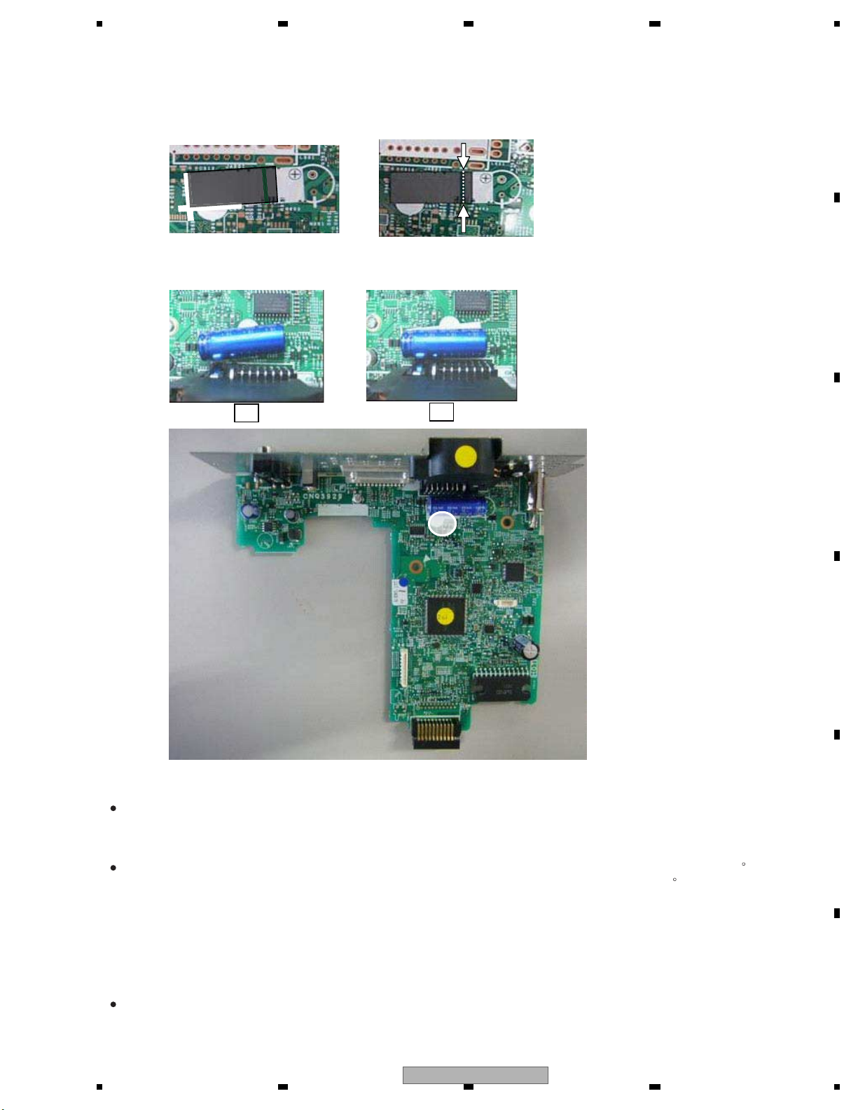
10. Capacitor Bond Lock (ES, ES1)
Silicon Glue (GEM1017)
Place the capacitor in the center of the silk print, and confirm it does not touch to the connector. Then, apply silicon glue.
OK
NG
9. Capacitor Bond Lock (EW5, ID)
Acetate Tape (GYH1026)
1 Please stick acetate tape along white line.
2 Please confirm line hiding with acetate tape.
* length of tape : 24±4mm
12
For environmental protection, lead-free solder is used on the printed circuit boards mounted in this unit.
Be sure to use lead-free solder and a soldering iron that can meet specifications for use with lead-free solders for repairs
accompanied by reworking of soldering.
Compared with conventional eutectic solders, lead-free solders have higher melting points, by approximately 40 C.
Therefore, for lead-free soldering, the tip temperature of a soldering iron must be set to around 373 C in general, although
the temperature depends on the heat capacity of the PC board on which reworking is required and the weight of the tip of
the soldering iron.
Compared with eutectic solders, lead-free solders have higher bond strengths but slower wetting times and higher melting
temperatures (hard to melt/easy to harden).
The following lead-free solders are available as service parts:
Parts numbers of lead-free solder:
GYP1006 1.0 in dia.
GYP1007 0.6 in dia.
GYP1008 0.3 in dia.
1.2 NOTES ON SOLDERING
DEH-6300SD/XNEW5
7

1234
1234
C
D
F
A
B
E
2. SPECIFICATIONS
General
Power source ..................14.4 V DC (10.8 V to 15.1 V al-
lowable)
Grounding system ............Negative type
Maximum current consumption
.................................10.0 A
Dimensions (W × H × D):
DIN
Chassis .............. 178 mm × 50 mm × 165
mm
Nose .................. 188 mm × 58 mm × 18
mm
D
Chassis .............. 178 mm × 50 mm × 165
mm
Nose ........... ... .... 170 mm × 46 mm × 18
mm
Weight ........................... 1.16 kg
Audio
Maximum power output ... 50 W × 4
70 W × 1/2 (for subwoofer)
Continuous power output
.................................22 W × 4(50 Hz to 15 000 Hz,
5 % THD, 4 load, both chan-
nels driven)
Load impedance .............4 (4 to 8 allowable)
Preout maximum output level
.................................4.0 V
Equalizer (5-Band Graphic Equalizer):
Frequency............ ... ..100/315/1.25k/3.15k/8k Hz
Gain .................... ... .. ±12 dB
HPF:
Frequency............ ... . 50/63/80/100/125 Hz
Slope ............... ... .....–12 dB/oct
Subwoofer (mono):
Frequency................ 50/63/80/100/125 Hz
Slope .......................–18 dB/oct
Gain ........................+6 dB to –24 dB
Phase ......................Normal/Reverse
Bass boost:
Gain ........................+12 dB to 0 dB
CD player
System ..........................Compact disc audio system
Usable discs ...................Compact disc
Signal-to-noise ratio ......... 94 dB (1 kHz) (IEC-A network)
Number of channels ........ 2 (stereo)
MP3 decoding format ...... MPEG-1 & 2 Audio Layer 3
WMA decoding format ..... Ver. 7, 7.1, 8, 9, 10, 11, 12 (2ch
audio)
(Windows Media Player)
AAC decoding format ....... MPEG-4 AAC (iTunes encoded
only) (.m4a)
(Ver. 9.2 and earlier)
WAV signal format ...........Linear PCM & MS ADPCM
(Non-compressed)
USB
USB standard specification
..................................USB 2.0 full speed
Maximum current supply
..................................500 mA
USB Class ...................... MSC (Mass Storage Class)
File system...................... FAT12,FAT16, FAT32
MP3 decoding format ...... MPEG-1 & 2 Audio Layer 3
WMA decoding format ..... Ver. 7, 7.1, 8, 9, 10, 11, 12 (2ch
audio)
(Windows Media Player)
AAC decoding format ....... MPEG-4 AAC (iTunes encoded
only) (.m4a)
(Ver. 9.2 and earlier)
WAV signal format ...........Linear PCM & MS ADPCM
(Non-compressed)
SD
Compatible physical format
.................................Version 2.00
Maximum memory capacity
.................................32 GB (for SD and SDHC)
File system......................FAT12, FAT16, FAT32
MP3 decoding format ...... MPEG-1 & 2 Audio Layer 3
WMA decoding format ..... Ver. 7, 7.1, 8, 9, 10, 11, 12 (2ch
audio)
(Windows Media Player)
AAC decoding format ....... MPEG-4 AAC (iTunes encoded
only) (.m4a)
(Ver. 9.2 and earlier)
WAV signal format ...........Linear PCM & MS ADPCM
(Non-compressed)
FM tuner
Frequency range ............. 87.5 MHz to 108.0 MHz
Usable sensitivity , mono, S/N:............ 9 dBf (0.8 µV/75
30 dB)
Signal-to-noise ratio ........ 72 dB (IEC-A network)
MW tuner
Frequency range .............. 531 kHz to 1602 kHz (9 kHz)
Usable sensitivity ............. 25 µV (S/N: 20 dB)
Signal-to-noise ratio ......... 62 dB (IEC-A network)
LW tuner
Frequency range .............. 153 kHz to 281 kHz
Usable sensitivity ............. 28 µV (S/N: 20 dB)
Signal-to-noise ratio ......... 62 dB (IEC-A network)
Note
Specifications and the design are subject to
modifications without notice.
Backup current ................. 5.0 mA or less
DEH-6300SD/XNEW5
2.1 SPECIFICATIONS
8
DEH-6300SD/XNEW5

5 678
56
7
8
C
D
F
A
B
E
(for subwoofer)
load, both chan-
General
Power source ...................14.4 V DC (12.0 V to 14.4 V al-
lowable)
Grounding system ............Negative type
Maximum current consumption
.................................10.0 A
Dimensions (W × H × D):
DIN
Chassis .............. 178 mm × 50 mm × 165
mm
Nose ........... ... .... 188 mm × 58 mm × 18
mm
D
Chassis .............. 178 mm × 50 mm × 165
mm
Nose .............. .... 170 mm × 46 mm × 18
mm
Weight ........................... 1.16 kg
Audio
Maximum power output ... 50 W × 4
70 W × 1/2
Continuous power output
.................................22 W × 4(50 Hz to 15 000 Hz,
5 % THD, 4
nels driven)
Load impedance .............4 (4 to 8 allowable)
Preout maximum output level
................................4.0 V
Equalizer (5-Band Graphic Equalizer):
Frequency............ ...100/315/1.25k/3.15k/8k Hz
Gain ......................±12 dB
HPF:
Frequency............ . ..50/63/80/100/125 Hz
Slope .................. ... –12 dB/oct
Subwoofer (mono):
Frequency............ ... 50/63/80/100/125 Hz
Slope .................. ....–18 dB/oct
Gain .......................+6 dB to –24 dB
Phase ......... ... .........Normal/Reverse
Bass boost:
Gain .......................+12 dB to 0 dB
CD player
System ....... ................... Compact disc audio system
Usable discs ...................Compact disc
Signal-to-noise ratio ......... 94 dB (1 kHz) (IEC-A network)
Number of channels ........ 2 (stereo)
MP3 decoding format ...... MPEG-1 & 2 Audio Layer 3
WMA decoding format ..... Ver. 7, 7.1, 8, 9, 10, 11, 12 (2ch
audio)
(Windows Media Player)
AAC decoding format ....... MPEG-4 AAC (iTunes encoded
only) (.m4a)
(Ver. 9.2 and earlier)
WAV signal format ...........Linear PCM & MS ADPCM
(Non-compressed)
USB
USB standard specification
.................................USB 2.0 full speed
Maximum current supply
.................................500 mA
USB Class .................. ....MSC (Mass Storage Class)
File system......................FAT12, FAT16, FAT32
MP3 decoding format ...... MPEG-1 & 2 Audio Layer 3
WMA decoding format ..... Ver. 7, 7.1, 8, 9, 10, 11, 12 (2ch
audio)
(Windows Media Player)
AAC decoding format ....... MPEG-4 AAC (iTunes encoded
only) (.m4a)
(Ver. 9.2 and earlier)
WAV signal format ...........Linear PCM & MS ADPCM
(Non-compressed)
SD
Compatible physical format
.................................Version 2.00
Maximum memory capacity
.................................32 GB (for SD and SDHC)
File system......................FAT12, FAT16, FAT32
MP3 decoding format ...... MPEG-1 & 2 Audio Layer 3
WMA decoding format ..... Ver. 7, 7.1, 8, 9, 10, 11, 12 (2ch
audio)
(Windows Media Player)
AAC decoding format ....... MPEG-4 AAC (iTunes encoded
only) (.m4a)
(Ver. 9.2 and earlier)
WAV signal format ...........Linear PCM & MS ADPCM
(Non-compressed)
FM tuner
Frequency range .............87.5 MHz to 108.0 MHz
Usable sensitivity , mono, S/N:............9 dBf (0.8 µV/75
30 dB)
Signal-to-noise ratio ........72 dB (IEC-A network)
AM tuner
Frequency range .............531 kHz to 1 602 kHz (9 kHz)
530 kHz to 1640 kHz (10 kHz)
Usable sensitivity ............25 µV (S/N: 20 dB)
Signal-to-noise ratio ........62 dB (IEC-A network)
Infrared remote control
Wavelength ....................940 nm ±50 nm
Output ...........................typ; 12 mw/sr per Infrared LED
Note
Specifications and the design are subject to
modifications without notice.
DEH-6350SD/XNES, XNES1, DEH-6390SD/XNID
Backup current ................. 5.0 mA or less
(DEH-6350SD/XNES, XNES1)
2.2 DISC/CONTENT FORMAT
DEH-6300SD/XNEW5
9
1234
1234
C
D
F
A
B
E
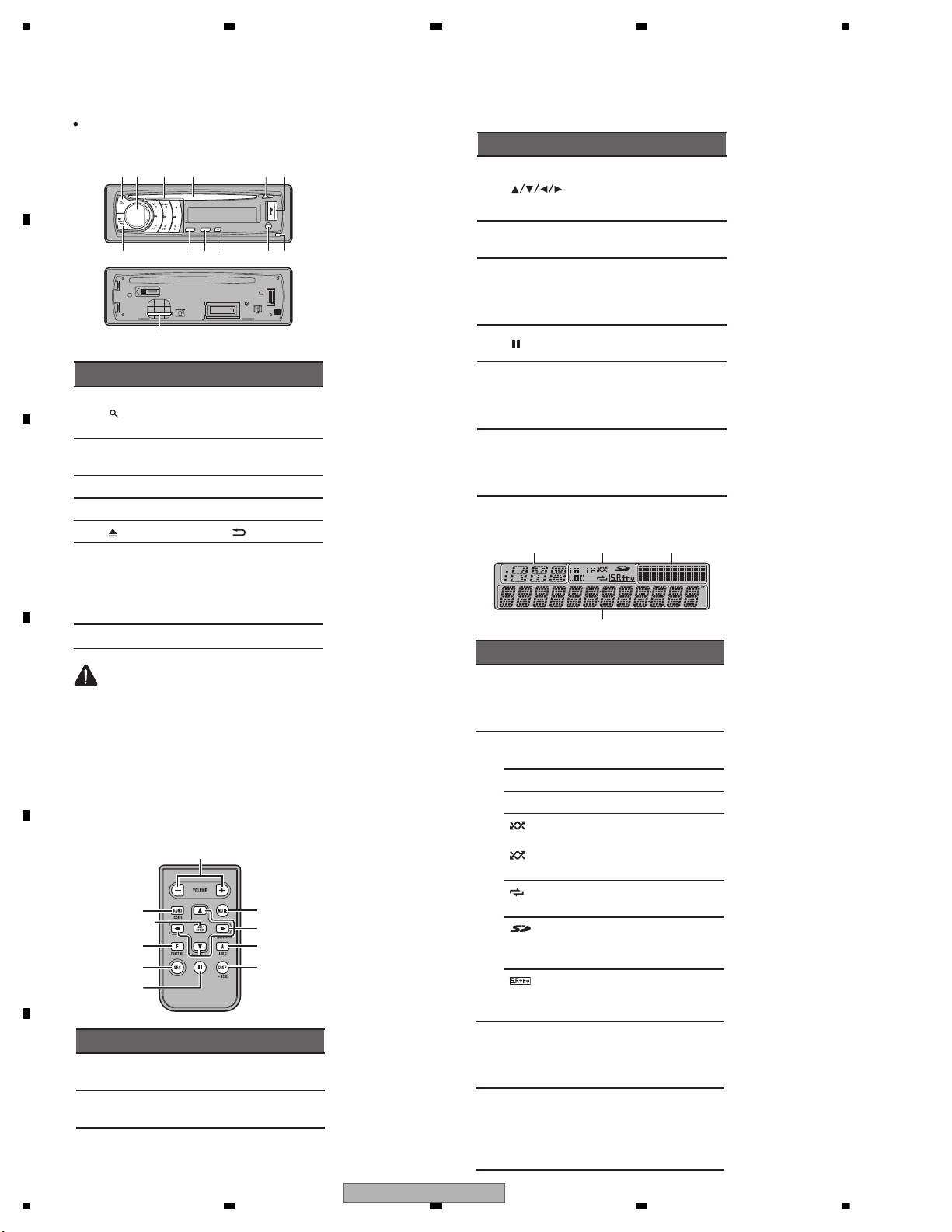
2.3 PANEL FACILITIES
Head unit
d
7
8
3
b
a9
c
61
2
4
5
Part Part
1
(list) 8
AUX input jack
(3.5 mm stereo
jack)
2
MULTI-CONTROL
(M.C.)
9 TA/NEWS
3 1 to 6 a BAND/ESC
4 Disc loading slot b SRC/OFF
5 (eject) c
/DISP/SCRL
6 USB port d
Removing the
front panel, you
canseetheSD
memory card
slot.
7 Detach button
CAUTION
Use an optional Pioneer USB cable (CD-U50E)
to connect the USB audio player/USB memory
as any device connected directly to the unit will
protrude out from the unit and may be dangerous.
Do not use unauthorized products.
Optional remote control
The remote control CD-R320 is sold separately.
e
l
j
b
a
f
i
hk
g
Part Operation
e VOLUME
Press to increase or decrease
volume.
f MUTE
Press to mute. Press again to
unmute.
g
Press to perform manual seek
tuning, fast forward, reverse
and track search controls. Also
used for controlling functions.
h AUDIO
Press to select an audio function.
i DISP/SCRL
Press to select different displays.
Press and hold to scroll
through the text information.
j
Press to pause or resume playback.
Part Operation
k
FUNCTION
Press to select functions.
Press and hold to recall the initial setting menu when the
sources are off.
l
LIST/
ENTER
Press to display the list depending on the source.
While in the operating menu,
press to control functions.
Display indication
1
4
2
3
Indicator State
1
Information display section
Source, band, and menu operation guides are displayed.
2
TA
TA (traffic announcement
standby) function is on.
LOC Local seek tuning is on.
TP A TP station is tuned in.
(ran-
dom)
(shuf-
fle)
The random function is on.
The iPod source is selected
and the shuffle or shuffle all
function is on.
(re-
peat)
The repeat function is on.
(SD
memory
card)
SD/SDHC memory card is inserted.
(sound retriever)
The sound retriever function is
on.
3
Level
meter display section
The levels of the audio outputs
are displayed.
4
Main display section
Tuner: frequency
Built-in CD, external storage
device (USB, SD) and iPod:
elapsed playback time and text
information
DEH-6300SD/XNEW5
10
DEH-6300SD/XNEW5
5 678
56
7
8
C
D
F
A
B
E
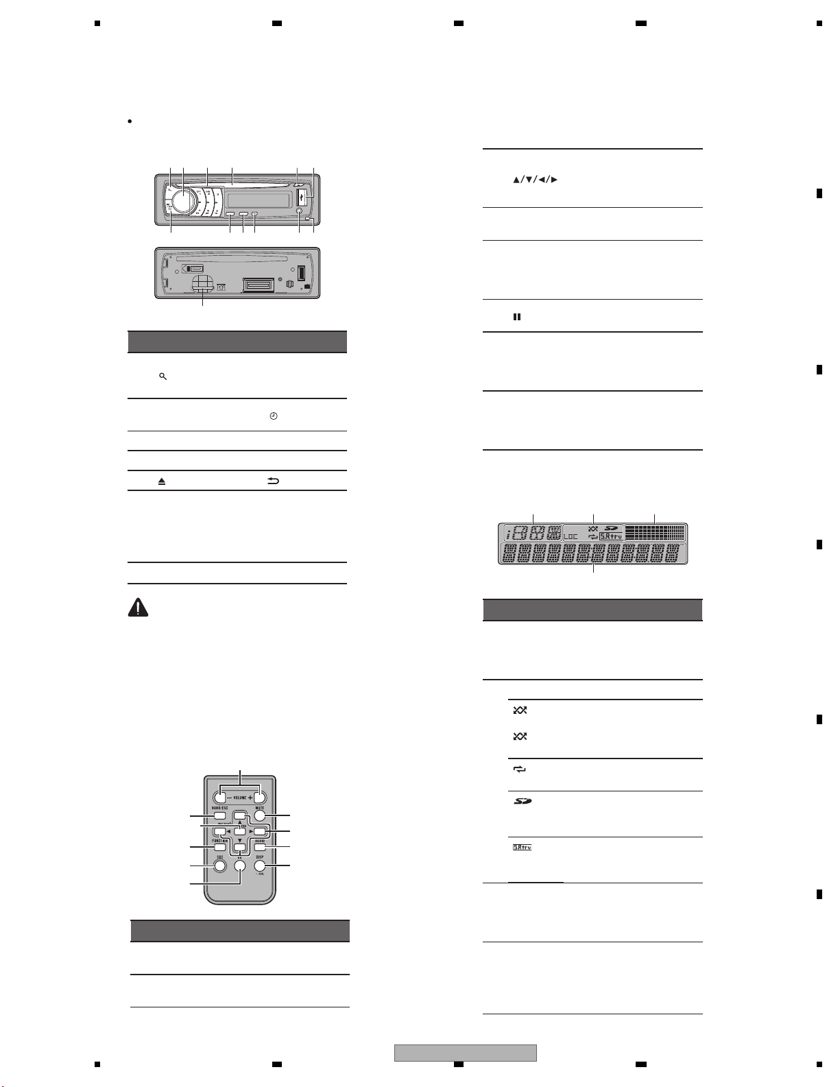
Head unit
d
7
8
3
b
a9c
61
2
4 5
Part Part
1
(list) 8
AUX input jack
(3.5mmstereo
jack)
2
MULTI-CONTROL
(M.C.)
9
/DISP OFF
3 1 to 6 a BAND/ESC
4 Disc loading slot b SRC/OFF
5 (eject) c
/DISP/SCRL
6 USB port d
Removing the
front panel, you
can see the SD
memory card
slot.
7 Detach button
CAUTION
Use an optional Pioneer USB cable (CD-U50E)
to connect the USB audio player/USB memory
as any device connected directly to the unit will
protrude out from the unit and may be dangerous.
Do not use unauthorized products.
Remote control
e
l
j
b
a
f
i
hk
g
Part Operation
e VOLUME
Press to increase or decrease
volume.
f MUTE
Press to mute. Press again to
unmute.
g
Press to perform manual seek
tuning, fast forward, reverse
and track search controls. Also
used for controlling functions.
h AUDIO
Press to select an audio function.
i DISP/SCRL
Press to select different displays.
Press and hold to scroll
through the text information.
j
Press to pause or resume playback.
k
FUNCTION
Press to select functions.
Press and hold to recall the initial setting menu when the
sources are off.
l
LIST/
ENTER
Press to display the list depending on the source.
While in the operating menu,
press to control functions.
Display indication
1
4
2 3
Indicator State
1
Information display section
Source, band, and menu operation guides are displayed.
2
LOC Local seek tuning is on.
(ran-
dom)
(shuf-
fle)
The random function is on.
The iPod source is selected
and the shuffle or shuffle all
function is on.
(re-
peat)
The repeat function is on.
(SD
memory
card)
SD/SDHC memory card is inserted.
(sound retriever)
The sound retriever function is
on.
3
Level
meter display section
The levels of the audio outputs
are displayed.
4
Main display section
Tuner: frequency
Built-in CD, external storage
device (USB, SD) and iPod:
elapsed playback time and text
information
DEH-6350SD/XNES, XNES1, DEH-6390SD/XNID
DEH-6300SD/XNEW5
11
1234
1234
C
D
F
A
B
E
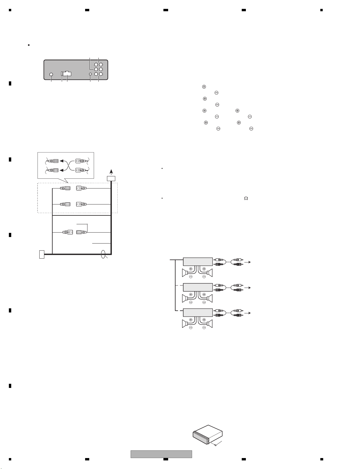
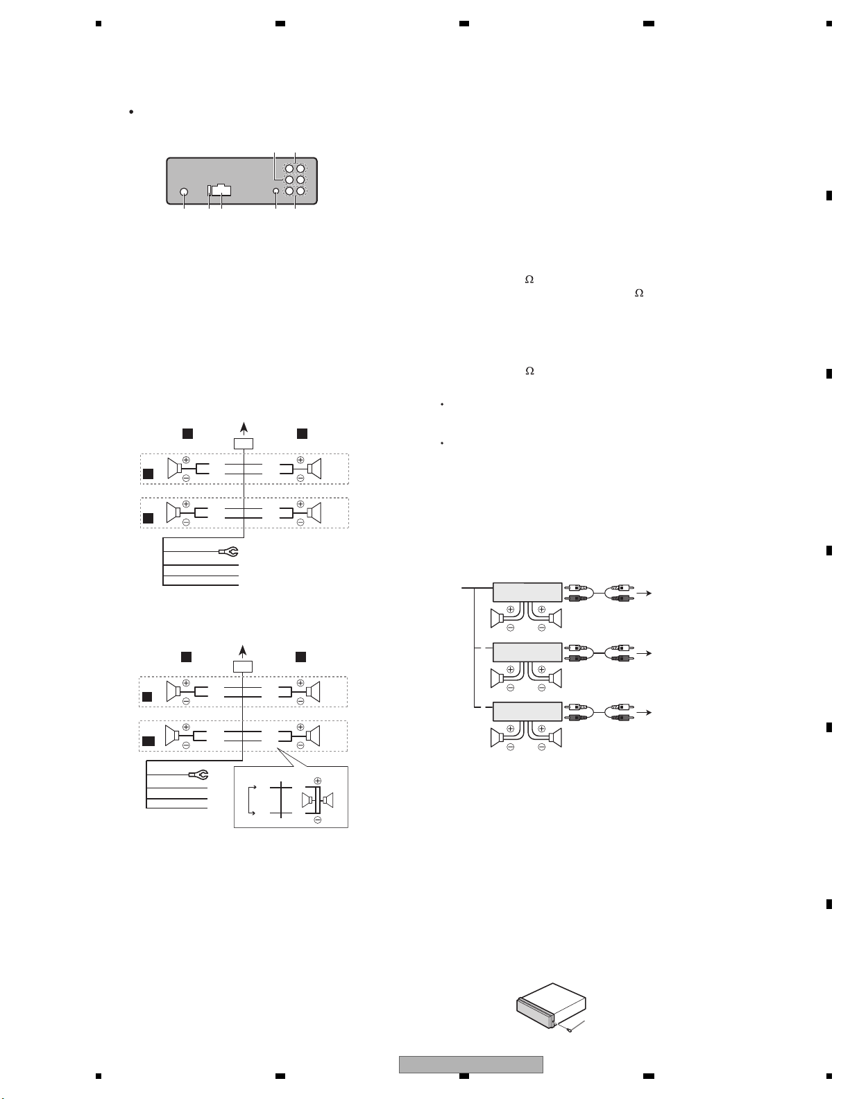
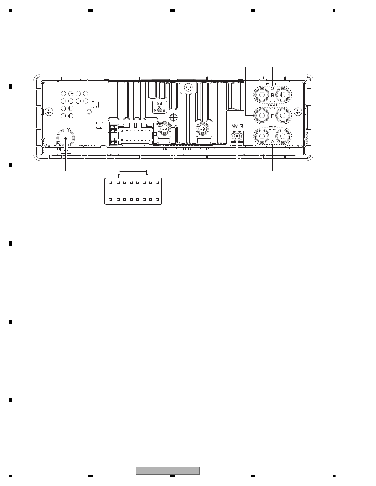
2.4 CONNECTION DIAGRAM
This unit
345 6 7
21
1 Front output
2 Rear output
3 Antenna input
4 Fuse (10 A)
5 Power cord input
6 Wired remote input
Hard-wired remote control adaptor can be
connected (sold separately).
7 Subwoofer output
Power cord
1
3
3
2
4
4
556
6
b
8
9
7
a
e
d
c
1 To power cord input
2 Depending on the kind of vehicle, the func-
tion of 3 and 5 may be different. In this
case, be sure to connect 4 to 5 and 6 to
3.
3 Yellow
Back-up (or accessory)
4 Yellow
Connect to the constant 12 V supply terminal.
5 Red
Accessory (or back-up)
6 Red
Connect to terminal controlled by ignition
switch (12 V DC).
7 Connect leads of the same color to each
other.
8 Black (chassis ground)
9 Blue/white
The pin position of the ISO connector will differ depending on the type of vehicle. Connect
9 and b when Pin 5 is an antenna control
type. In another type of vehicle, never connect 9 and b.
a Blue/white
Connect to system control terminal of the
power amp (max. 300 mA 12 V DC).
b Blue/white
Connect to auto-antenna relay control terminal (max. 300 mA 12 V DC).
c Yellow/black
If you use an equipment with Mute function,
wire this lead to the Audio Mute lead on that
equipment. If not, keep the Audio Mute lead
free of any connections.
d Speaker leads
White: Front left
White/black: Front left
Gray: Front right
Gray/black: Front right
Green: Rear left or subwoofer
Green/black: Rear left or subwoofer
Violet: Rear right or subwoofer
Violet/black: Rear right or subwoofer
e ISO connector
In some vehicles, the ISO connector may be
divided into two. In this case, be sure to connect to both connectors.
Notes
Change the initial setting of this unit. Refer
to SW CONTROL (rear output and subwoofer
setting).
The subwoofer output of this unit is monaural.
When using a subwoofer of 70 W (2 ), be
sure to connect the subwoofer to the violet
and violet/black leads of this unit. Do not
connect anything to the green and green/
black leads.
Power amp (sold separately)
Perform these connections when using the optional amplifier.
1
1
3
2
4
55
3
2
6
77
1
3
2
8
99
1 System remote control
Connect to Blue/white cable.
2 Power amp (sold separately)
3 Connect with RCA cables (sold separately)
4 To Rear output
5 Rear speaker
6 To Front output
7 Front speaker
8 To subwoofer output
9 Subwoofer
Fastening the front panel
If you do not plan to detach the front panel,
the front panel can be fastened with the supplied
screw.
Screw : XXX7020
DEH-6300SD/XNEW5
12
DEH-6300SD/XNEW5
5 678
56
7
8
C
D
F
A
B
E
This unit
34
5
6
7
21
1 Front output
2 Rear output
3 Antenna input
4 Fuse (10 A)
5 Power cord input
6 Wired remote input
Hard-wired remote control adaptor can be
connected (sold separately).
7 Subwoofer output
Power cord
Perform these connections when not connecting a rear speaker lead to a subwoofer.
1
8
9
c
d
6
32
4
5
7
a
b
e
f
h
g
RL
F
R
Perform these connections when using a subwoofer without the optional amplifier.
1
8
9
c
d
6
32
4
7
a
b
a
b
e
f
h
g
RL
F
SW
i
j
d
c
k l
1 To power cord input
2 Left
3 Right
4 Front speaker
5 Rear speaker
6 White
7 White/black
8 Gray
9 Gray/black
a Green
b Green/black
c Violet
d Violet/black
e Black (chassis ground)
Connect to a clean, paint-free metal location.
f Yellow
Connect to the constant 12 V supply terminal.
g Red
Connect to terminal controlled by ignition
switch (12 V DC).
h Blue/white
Connect to system control terminal of the
power amp or auto-antenna relay control terminal (max. 300 mA 12 V DC).
i Subwoofer (4 )
j When using a subwoofer of 70 W (2 ), be
sure to connect the subwoofer to the violet
and violet/black leads of this unit. Do not
connect anything to the green and green/
black leads.
k Not used.
l Subwoofer (4 )× 2
Notes
With a 2 speaker system, do not connect anything to the speaker leads that are not connected to speakers.
Change the initial setting of this unit. Refer
to SW CONTROL (rear output and subwoofer
setting).
The subwoofer output of this unit is monaural.
Power amp (sold separately)
Perform these connections when using the optional amplifier.
1
1
3
2
4
55
3
2
6
77
1
3
2
8
99
1 System remote control
Connect to Blue/white cable.
2 Power amp (sold separately)
3 Connect with RCA cables (sold separately)
4 To Rear output
5 Rear speaker
6 To Front output
7 Front speaker
8 To subwoofer output
9 Subwoofer
Fastening the front panel
If you do not plan to detach the front panel,
the front panel can be fastened with the supplied
screw.
Screw : XXX7020
DEH-6350SD/XNES, XNES1, DEH-6390SD/XNID
DEH-6300SD/XNEW5
13
1234
1234
C
D
F
A
B
E
3. BASIC ITEMS FOR SERVICE
demrifnocebotmetIserudecorP.oN
1 Confirm whether the customer complain has
been solved.
If the customer complain occurs with the
specific media, use it for the operation check.
The customer complain must not be
reappeared.
Display, audio and operations must be
normal.
2 CD Play back a CD.
(Track search)
No malfunction on display, audio and
operation.
3 FM/AM tuner Check FM/AM tuner action.
(Seek, Preset)
Switch band to check both FM and AM.
Display, audio and operations must be
normal.
4 Check whether no disc is inside the product. The media used for the operating check must
be ejected.
retfaecnaraeppastinotridrosehctarcsoNkcehcecnaraeppA5
receiving it for service.
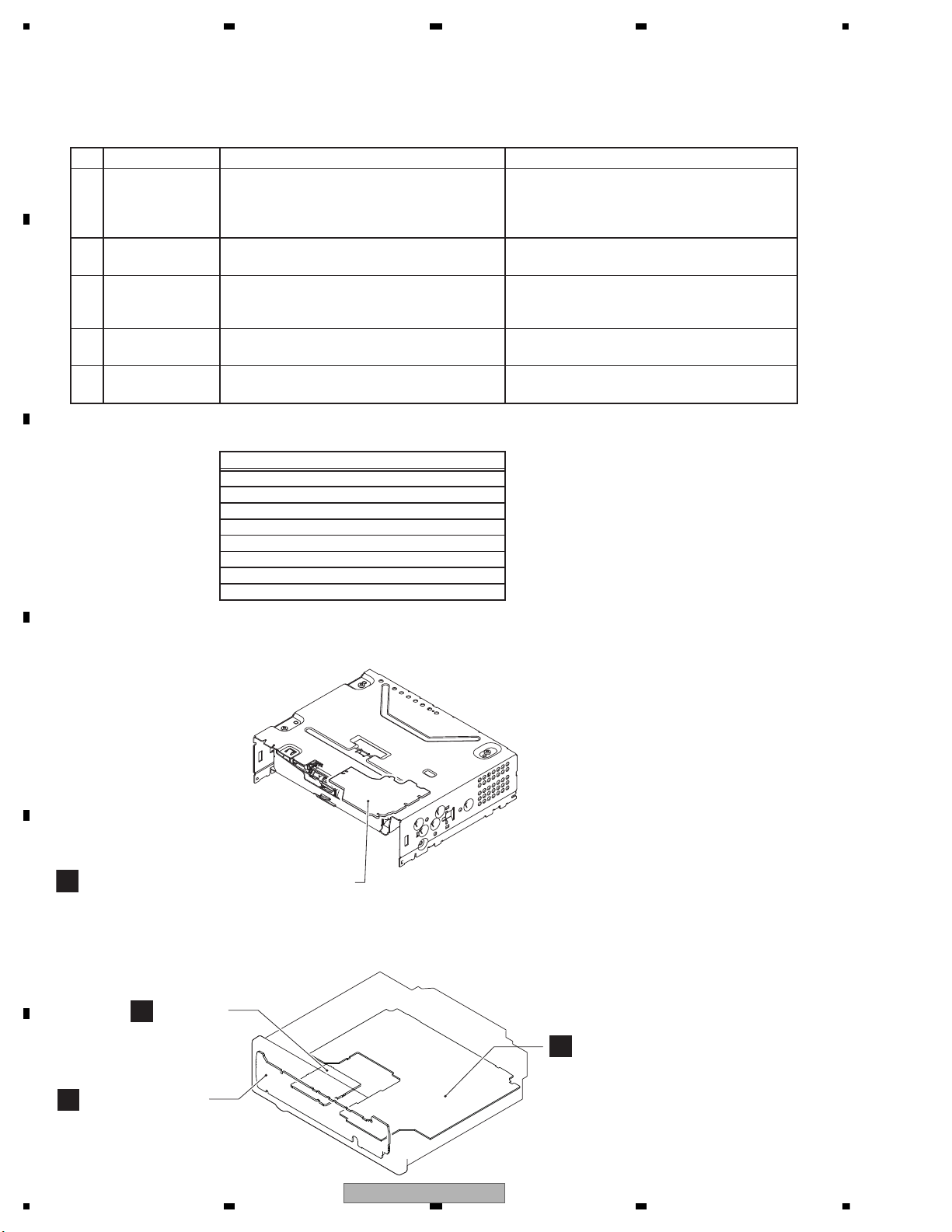
Item to be checked regarding audio
A
D
SD Unit
CD Core Unit (S11.1STD-DOUT)
C
Tuner Amp Unit
B
Keyboard Unit
A:DEH-6300SD/XNEW5
B:DEH-6350SD/XNES
C:DEH-6350SD/XNES1
D:DEH-6390SD/XNID
Unit Number : YWM5506(A)
: YWM5508(B,C)
: YWM5510(D)
Unit Name : Tuner Amp Unit
Unit Number : (A)
: (B,C)
: (D)
Unit Name : Keyboard Unit
Unit Number : CWX3985
Unit Name : CD Core Unit
(S11.1STD-DOUT)
Unit Number : YWM5516
Unit Name : SD Unit
3.1 CHECK POINTS AFTER SERVICING
To keep the product quality after servicing, please confirm following check points.
See the table below for the items to be checked regarding audio:
Distortion
Noise
Volume too low
Volume too high
Volume fluctuating
Sound interrupted
3.2 PCB LOCATIONS
14
DEH-6300SD/XNEW5
5 678
56
7
8
C
D
F
A
B
E
- Jigs List
- Grease List
Name
Grease
Grease
Grease
Grease
Silicon Glue
Grease No.
GEM1024
GEM1038
GEM1043
GEM1045
GEM1017
Remarks
CD Mechanism Module
CD Mechanism Module
CD Mechanism Module
CD Mechanism Module
Capacitor Bond Lock
Name
G
Name
16P FFC
Test Disc
L.P.F.
Acetate Tape
Jig No.
GGD1310
TCD-782
GYH1026
Remarks
Tuner Amp Unit - CD Core Unit
Checking the grating
Checking the grating (Two pieces)
Capacitor Bond Lock
Before shipping out the product, be sure to clean the
following portions by using the prescribed cleaning
tools:
Portions to be cleaned Cleaning tools
CD pickup lenses Cleaning liquid : GEM1004
Cleaning paper : GED-008
3.3 JIGS LIST
3.4 CLEANING
rease No.
emarks
DEH-6300SD/XNEW5
15
1234
1234
C
D
F
A
B
E
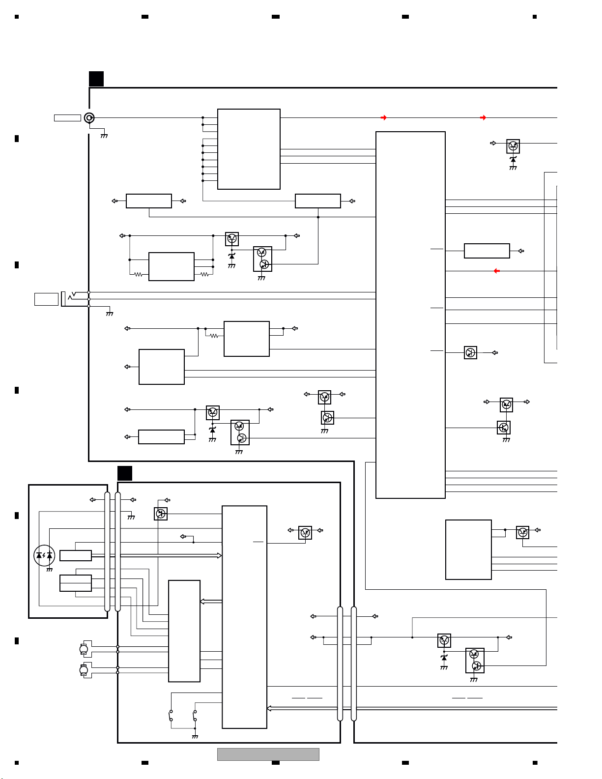
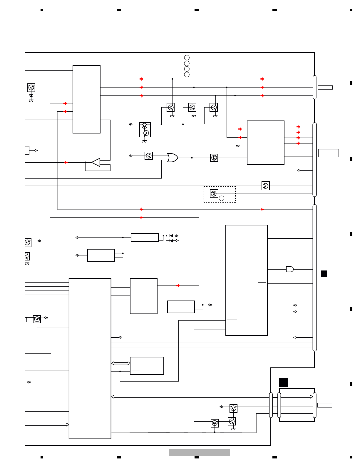
4. BLOCK DIAGRAM
JA401
1
2,3
ANTENNA
16
VDD33V
8
9
RESET
Q901
15
16
Q902
Q921(1/2)
DALMON
45
Q841
Q842
Q821
SWVDD
47
VDCONT
19
49
VD
VDD
RF FRONT END IC
IC401
TDA7706
5
FMMIXIN1
18
LNAIN
1
FMPINDRV
8
VCCRF
13
VCCVCO
27
VDIG
28
VCCREG1V2
51
VCC-REF
59
VCC-ADC_DAC
60
VCC-PLL
JA661
ILM+B
BUP
Q822
SYSTEM MICRO
COMPUTER
IC601
PEG731A8 : EW
PEG733A8 : ES,ES1,ID
(1/2)
TUSDA
TUSCL
33
34
57
75
76
KEYAD
92
SYNC
24
KEYD
32
USBCTL
36
USBFLG
23
I2CSDA
TUNRST
31
74
SYSPW
46
RSTN
I2CSCL
DACOUTL
RESET
ASENS
BSENS
10
LVLINL
91
ILMPW
5
1
EN/SYNC
PVIN
8
2
VIN
SW
DD5V REG.
IC161
BD9008F
3
4
FLG
1
EN
VIN
VIN
USB5V REG.
IC151
R5523N001B
VDT
VST
VCK
53
55
54
MUTE
48
18
VOUT
4
1
TUNER 5V REG.
IC451
NJM2886DL3-05
2
VIN
CONT
M
LD
MD
SPINDLE
M
LOADING/CARRIAGE
LD-
MD
15
5
HOLOGRAM
RF AMP, CD DECODER, MP3&WMA DECODER
2
VD
VD
9
16
VO3-
15
VO3+
18
VO4-
17
VO4+
21
CNT
9
MUTE
TD,FD
AC,BD,E,F
SD,MD
LD+
14
1
LD
2
PD
CONT
CLCONT
HOME
35
40
39
VDD
1
VDD
VDD
15
5
FOCUS ACT.
TRACKING ACT.
FOP
TOP
2
1
TOP
FOP
11
VO1-
14
VO2+
2
1
14
DSCSNS
38
29
RESET
8
RESET
88
VREF
REFO
93
REFOUT
3
3
FOM
FOM
12
VO1+
4
4
TOM
TOM
13
VO2-
22
LDIN
LOEJ
41
54
PUEN
V+3A
VDD
UNIT
MOTOR
MOTOR
ACTUATOR/
MOTOR DRIVER
BA5839FP
HOMEDSCSNS
PE5756A
DIGITAL SERVO/DATA • PROCESSOR
CPU, USB HOST CONTROLLER
CN701 CN701
Q101
CN101
Q102
IC301
S901
S903
IC201
V+3A
12
12
VCC
PD
REFO
LD+
SOP
SOM
LCOP
LCOM
PICKUP UNIT
(P10.5)(SERVICE)
GND
CD DATA (CDSRQ,CDSTBY,SKIP,
SCL,SDA,DATA,BCLK,LRCK,WAIT)
CD DATA (CDSRQ,CDSTBY,SKIP,
SCL,SDA,DATA,BCLK,LRCK,WAIT)
SYS8V
VDD5V
2
3
1
WIRED
REMOTE
KEYAD
KEYD
GND
A
CDL
TUNL
VOUT
2
4
SYS+B REG.
IC911
NJM2388F84
1
1
VDD3.3V REG.
IC901
S-1132B33-U5
5
VIN
CONTROL
BUP
OUT VDD
POWER ON RESET
IC651
S-80827CNMC-B8M
2
VDD33V
BUP
BUP
BUP
15V
Q201
SYS8V
SWVDD
VOUT
VOUT
5
USB5V
VDD5V
VDD33V
DD5V
TUNER AMP UNIT
A
CD CORE UNIT(S11.1STD-DOUT)
C
12
2
4
13
I2C_SCL
nRESET
MODE1
5
VCC
I2C_SDA
iPod CP
IC591
341S2162
MED33V
Q591
Q751
BUP
Q752
ILM+B
MECHA VD
BSENS
SWVDD
VDD5V REG.
Q832
Q831
8
6
V+
7
SI
BUP15V
HI-OUT 14V
4
INV
4
SW
CD
1
5
CS
INVIN
DC-DC CONVERTER
IC831
NJM2360M
MEDMUTE
MED_RX
MEDSTBY
MED_TX
43
41
34
33
1
TELIN
40
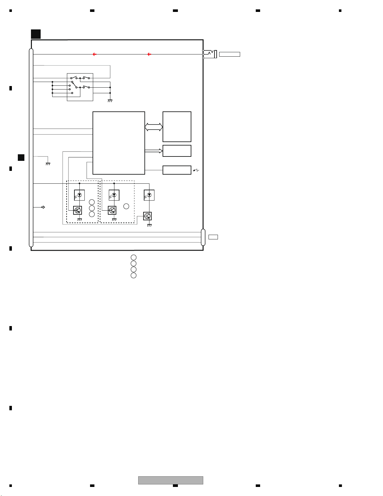
4.1 BLOCK DIAGRAM
16
DEH-6300SD/XNEW5
5 678
56
7
8
C
D
F
A
B
E
9
7
3
5
OUT1(-)
OUT1(+)
OUT2(-)
OUT2(+)
FL2
FL1
RL2
RL1
BRE1
ACC1
22
MUTE
CN801
13
18
7
5
1
3
JA981
20
ROT0
1
ROT1
95
DPDT
29
KYDT
IN1
11
3
30
DSENS
17
IN2
12
STBY
4
25
H-SW/VOS-DET
14
4
2
10
AUXL
14
Q382
Q921(2/2)
AMP
IC351
PA2030A
JA301
ILM+B
SYSTEM MICRO
COMPUTER
IC601
(2/2)
Q303 Q302 Q301
RESET
23
DATA
STB
S4B-L
36
E. VOL
IC201
PM9012A
39
S1Q+L
20
VCCH
35
S5B+L
CLK
21
22
31
SOL
13
6
1
4
JOYST
2
8
D-
VBUS(US5V)
D+
15
17
42
IC801
TC7SET08FUS1
ILM+B
BUP
5
SWVDD
SD DATA (DATA0 - DATA3, CLK, CMD)
27
OUTPL
SWL
26
OUTRL
RL
25
OUTFL
FL
RCA OUT
SOURCE
CONNECTOR
RL
6
FL
FR/SWL
AUXL
ROT1
JOYST
KYDT
DPDT
DSENS
SW5V
ROT0
CDL
TUNL
ET
AMP
IC241
NJM4558MD
2
VDD33V
Q381
Q361
BUP
SYS8V
BUP
Q201
1
3
2
+
-
SD_CD
114
VDSENS
85
CDRST
113
CP_SCL
CP_SDA
CPPWR
149
111
148
CPRST
112
FLASH ROM
IC571
CWW2867
MED33V
Q591
CN1202
942
7
CN781
10
4
JA1203
SD UNIT
D
SD_CD
SD33V
SD_CD CD1
SD33V
BUP
DAC5V REG.
IC182
NJM2872F05
SYS8V
5
MED33V
Q781
Q782
Q783
SDCTL
MEDRST
DAC
IC181
WM8761GED
MEDIA uCOM
IC501
R5S7262ZD144FPU
RESET
43
DM
70
DP
71
9
VOUTL
8
VDD
CDL
CN1
B
1
VIN
VOUT
CONT
3
80
21
12
ASENS
SD CARD
MEDIAMUTE
SYS_TXD
BRST
SYS_RXD
59
58
63
61
1
MED33V REG.
IC581
S-1172B33-E6
6
VDD5V
MED33V
MED12V
MED12V REG.
IC583
BH12PB3WHFV
3
VIN
VOUT
VIN
STBY
1
VOUT
4
DD5V
3
ON/OFF
BCKIN
MCLK
LRCIN
DIN
DEEMPH
DACSCK
DACCLK
DACLRCK
DACDATA
DACDATA1
139
138
137
136
105
3
1
2
14
12
SD_WP
115
MED33V
SD33V REG.
VDD
USB5V
MUTE
MUTE
MUTE
:DEH-6300SD/XNEW5
:DEH-6350SD/XNES
:DEH-6350SD/XNES1
A
B
C
:DEH-6390SD/XNID
D
TEL1
9
Q951
A
TELMUTE
PEG731A8 : EW
PEG733A8 : ES,ES1,ID
DEH-6300SD/XNEW5
17
1234
1234
C
D
F
A
B
E
KEYBOARD UNIT
B
CN1
AUXL
14
ROT0
8
ROT1
4
JOYST
6
ROTARY COMMANDER
S13
1
Phase_A 10 Phase_B
3A 2 Enc_Com
4B
7C
8D
9Push
5 Com
6 GND
CN3
AUXR
AUXL
AUXG
3
2
1
FRONT_AUX
KYDT
3
DPDT
1
CN801
20
A
10
5
DSENS
ILM+B
SW5V
VBUS(US5V)
13
D-
15
D+
17
49
TXD
50
RXD
LCD DRIVER/
KEY CONTROLLER
IC1
POUT1
POUT2
POUT3
2
PD6538A
4
Q1
3
D18 - D34,
D45, D46
A
48
58
59
D1 - D17,
D43, D44
B
1
5
C
Q1
D
6
KDT1-3
KEY MATRIX
KST1-4
LCD
V1
REMOTE CONTROL
Q2
1
D35
SENSOR
IC2
GP1UXC14RK
57
REM
A
:DEH-6300SD/XNEW5
B
:DEH-6350SD/XNES
:DEH-6350SD/XNES1
C
:DEH-6390SD/XNID
D
CN2
VBUS(US5V)
5
D-
4
USB
D+
3
18
DEH-6300SD/XNEW5
5 678
56
7
8
C
D
F
A
B
E
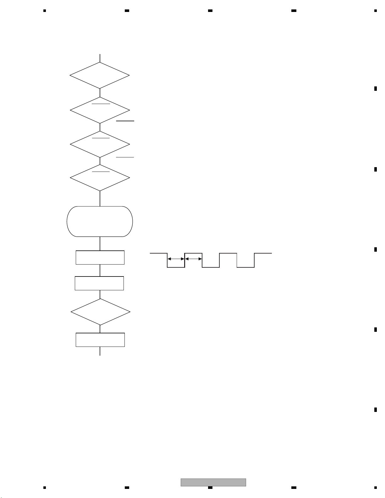
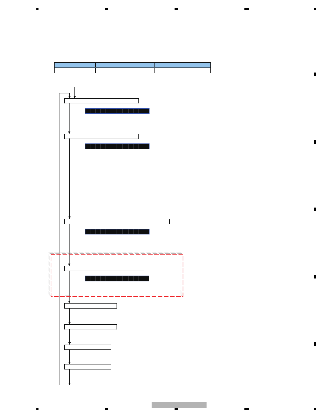
VCC = 3.3 V
Pin 14
BSENS
Pin 16
ASENS
Pin 18
BSENS = L
Starts
communication
with Grille
microcomputer.
SWVDD <- H
Pin 47
Source keys
operative
Source ON
SYSPW <- H
Pin 46
500 ms
500 ms
Completes power-on operation.
(After that, proceed to each source operation)
In case of the above signal, the communication
with Grille microcomputer may fail.
If the time interval is not 500 msec, the oscillator
may be defective.
Power ON
ASENS = L
DSENS
Pin 17
5. DIAGNOSIS
5.1 OPERATIONAL FLOWCHART
DEH-6300SD/XNEW5
19
1234
1234
C
D
F
A
B
E
5.2 ERROR CODE LIST
8-digit display 6-digit display 4-digit display
ERROR-xx ERR-xx E-xx
(2) LIST OF CD ERROR CODES (Error Mode: 0xFD)
Code Classification
Error code to be displayed
Details and possible causes
10 Servo Carriage Home NG The CRG cannot move toward the inner track.
The CRG cannot move from the inner track.
--> Defective HOME SW; Failure in CRG movement.
7
Servo TOC reading NG TOC information cannot be read.
--> The partial disk or TOC content is illegal.
11
Servo Focus Search NG Focusing not available
--> Disc placed upside-down; Stains on the disc; excessive vibration.
17 Servo Setup NG AGC protection does not work. Focus can be easily lost.
--> Scratches or stains on the disc; excessive vibration.
15 Servo Failure in RF data RF not read
--> A CD-R disc that does not contain data loaded
--> A CD-RW disc that does not contain data loaded
12
Servo Spindle Lock NG
Subcode NG
RF-amp NG
Spindle not locked. Subcode not readable.
Proper RF AMP gain not obtained.
--> Defective spindle; Scratches or stains on the disc; excessive vibration.
-->
A CD-R disc that does not contain data loaded, or in a rare case, disc placed upside-down.
--> CD signal error.
30
Servo Search Time Out Failed to reach a target address
--> CRG tracking error; Scratches on the disc; Stains on the disc
50 Mechanism Failure in ejection
Load NG
Disc ejection not completed
Disc loading not completed
--> A foreign object inserted in the mechanism; Disc jammed.
51
Mechanism Failure in retried
turning for ejection
Disc could not be ejected even after disc turning had been retried.
--> A foreign object inserted in the mechanism; Disc jammed.
NOTES
• Indications of error codes are available only during disc operations, because CD operations are
unavailable if a mechanical error is generated.
• If the TOC cannot be read, this is not processed as an error, and operation continues accordingly.
• If you design a new head unit, be sure to use one of the display formats indicated in “Display example of
the main unit.”
ERROR CODES
(1) DISPLAY METHOD
If “0xFD” error mode is displayed in CD MODE (CD MODE area for display), an error code will be displayed in the MIN (minute
display) and SEC (second display) areas.
The same code is displayed in the MIN and SEC areas.
The TNO area is blank (#0FFH), as it conventionally was.
• Display example of the main unit
Depending on the display capability of LCDs, the display format varies, as shown below. XX denotes an error number.
Note: In a case of an OEM product, the error display format is subject to the specifications used by the equipment
manufacturer.
If a CD memory device is inoperable, or operation of such media is stopped by an error, the error mode is established and a
cause of the error is displayed by an error code. Indication of error codes is intended to reduce the number of calls from
customers and facilitate failure analysis and repair work in servicing.
• The 2 high-order digits of an error code denote the main
classification, shown below.
0x: Servo-related errors
1x: Servo-related errors
3x: Servo-related errors
5x: Mechanism-related errors
• How to restore from each error is shown below.
0x, 1x and 3x: ACC-OFF then ON, CD-OFF then ON,
Disc ejection
5X: ACC-OFF then ON, Disc ejection, Disc reloading
20
DEH-6300SD/XNEW5
5 678
56
7
8
C
D
F
A
B
E
External storage device (USB, SD)/iPod
Message Cause Action
NO DEVICE When plug and
play is off, no
USB storage device or iPod is
connected.
Turn the plug
and play on.
Connect a compatible USB storage device/iPod.
FORMAT
READ
Sometimes
there is a delay
between the
start of playback
and when you
start to hear any
sound.
Wait until the
message disappears and you
hear sound.
NO AUDIO There are no
songs.
Transfer the audio
files to the USB
storage device
and connect.
The connected
USB storage device has security enabled
Follow the USB
storage device instructions to disable the security.
SKIPPED The connected
USB storage device contains
files embedded
with Windows
Media DRM 9/
10
Play an audio file
not embedded
with Windows
Media DRM 9/10.
PROTECT All the files in
the USB storage
device are embedded with
Windows Media
DRM 9/10
Transfer audio
files not embedded with
Windows Media
DRM 9/10 to the
USB storage device and connect.
N/A USB The connected
USB storage device is not supported by this
unit.
Connect a USB
Mass Storage
Class compliant
device.
Disconnect
your device and
replace it with a
compatible USB
storage device.
Non-compatible
iPod
Disconnect your
device and replace it with a
compatible iPod.
N/A SD Non-compatible
SD storage device
Remove your device and replace it
with a compatible
SD storage device.
CHECK USB The USB con-
nector or USB
cable has shortcircuited.
Check that the
USB connector or
USB
cable is not
caught in something or damaged.
Message Cause Action
CHECK USB The connected
USB storage device consumes
more than 500
mA (maximum
allowable current).
Disconnect the
USB storage device and do not
use it. Turn the
ignition switch to
OFF, then to ACC
or ON and then
connect only
compliant USB
storage devices.
CHECK USB The iPod oper-
ates correctly
but does not
charge
Make sure the
connection cable
for the iPod has
not shorted out
(e.g., not caught
in metal objects).
After checking,
turn the ignition
switch OFF and
back ON, or disconnect the iPod
and reconnect.
ERROR-19 Communication
failed.
Perform one of
the following operations.
–Turn the ignition
switch OFF and
back ON.
–Disconnect or
eject the external
storage device.
–Change to a different source.
Then, return to
the USB or SD
source.
Disconnect the
cable from the
iPod. Once the
iPod's main menu
is displayed, reconnect the iPod
and reset it.
ERROR-19 iPod failure Disconnect the
cable from the
iPod. Once the
iPod's main menu
is displayed, reconnect the iPod
and reset it.
ERROR-23 USB storage de-
vice was not formatted with
FAT12, FAT16 or
FAT32
USB storage device should be formatted with
FAT12, FAT16 or
FAT32.
ERROR-16 The iPod firm-
ware version is
old
Update the iPod
version.
iPod failure Disconnect the
cable from the
iPod. Once the
iPod's main menu
is displayed, reconnect the iPod
and reset it.
STOP There are no
songs in the
current list.
Select a list that
contains songs.
NOT FOUND No related
songs
Transfer songs to
the iPod.
DEH-6300SD/XNEW5
21
1234
1234
C
D
F
A
B
E
5.3 CONNECTOR FUNCTION DESCRIPTION
ANTENNA
1 FL+
2 FR+
3 FL4 FR5 RL+
6 RR+
7 RL8 RR-
9 TELMUTE (DEH-6300SD/XNEW5)
10 NC
11 NC
12 NC
13 ACC
14 B.REM
15 B.UP
16 GND
16
14
12
10 8
6
42
15
13
11
97
5
31
WIRED
REMOTE
CONTROL
FRONT
OUTPUT
REAR
OUTPUT
SUBWOOFER
OUTPUT
22
DEH-6300SD/XNEW5
5 678
56
7
8
C
D
F
A
B
E
The information such as the system version is checked and the lighting of every segment on the display is checked.
[Operation key]
[Test item]
Test mode is started
System Version information is displayed
S$$$$ ###
$ PEG number For PEG123A, "123A" is displayed
# System microcomputer version For Ver.7.01, "701" is displayed
Unit number information is displayed
U %%%% % % %
% System unit number For CWW1234, "CWW1234" is displayed
Media microcomputer Version information is displayed
MV $ $ # #
$ Major version
# Minor version
Manufacture_ID information is displayed
MID $ $ $ $$$$$
$ Manufacture ID
Display is normally updated
Usual product operation is implemented to outward appearances.
Display update is stopped
The screen gets still when entering this item.
Every segment lights up
Every segment including icons lights up.
Every segment goes out
Every segment including icons goes out.
Corresponding key Processing Remarks
BAND + 1 KEY Switching to next test display Also used as an entry key
Only /UC model
6. SERVICE MODE
6.1 DISPLAY TEST MODE
DEH-6300SD/XNEW5
23
1234
1234
C
D
F
A
B
E
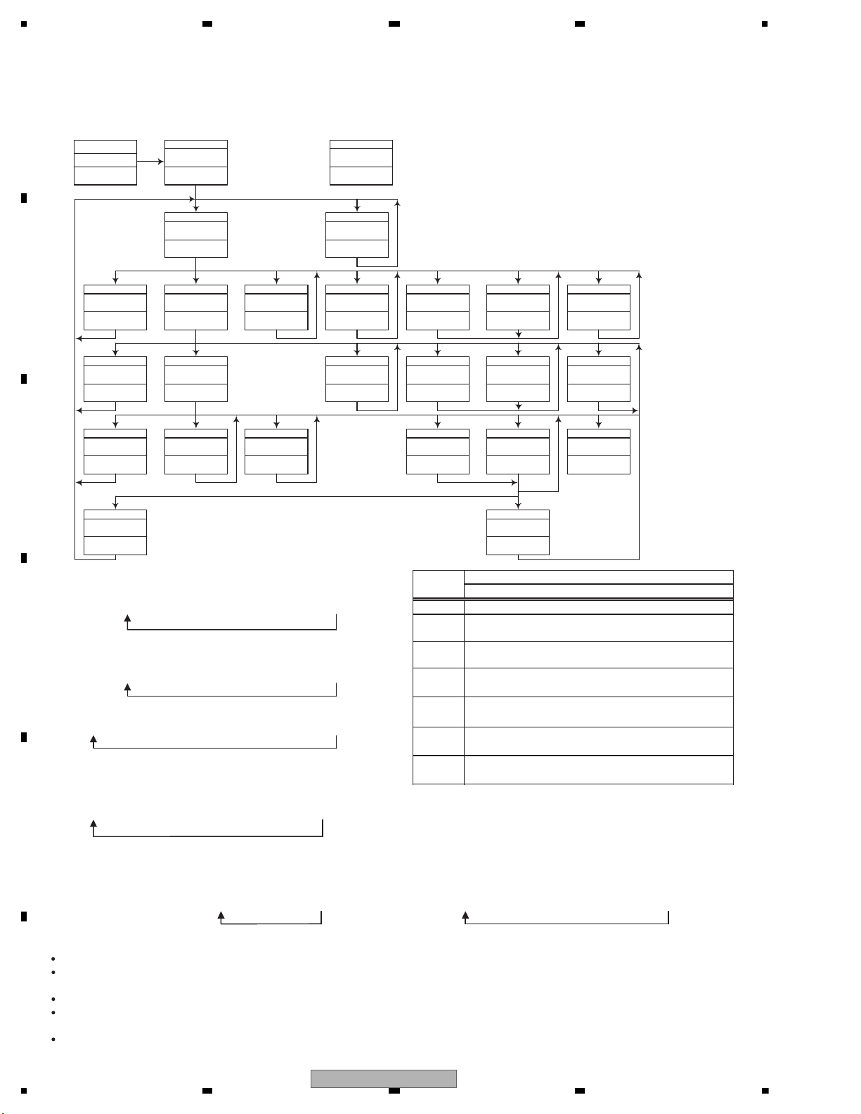
6.2 CD TEST MODE
[Key]
Contents
Display
[BAND]
Power On
(T.Offset is adjusted)
TRK MIN SEC
00 00 00
[2]
RF AMP
Gain switching
GG GG GG
*1
[3]
Focus Close
S curve check
TRK MIN SEC
91 91 91
[6]
Focus Mode switching
0X 0X 0X
*2
[1]
Tracking Servo
Close
00 00 00
or 99 99 99
[<]
CRG +
[2]
Self-adjusting
switching
TRK MIN SEC
?? ?? ??
*3*8
[>]
CRG -
*8
[BAND]
Power Off
TRK MIN SEC
[BAND]
Power Off
TRK MIN SEC
[BAND]
Power Off
TRK MIN SEC
[BAND]
Power Off
TRK MIN SEC
[1]
T.Close & AGC
Applicable servomechanism
TRK MIN SEC
?tr ?min ?sec
[3]
RF AGC /
RF AGC coefficient display
[<]
CRG +
8X 8X 8X
or 9X 9X 9X
[2]
T.Balance adjustment /
T.BAL coefficient display
TRK MIN SEC
?? ?? ??
[>]
CRG -
?? ?? ??
[1]
F,T,RF AGC
F.Bias display switching
TRK MIN SEC
TRK MIN SEC
TRK MIN SEC
[3] [<]
CRG/TR Jump +
[2]
Tracking Open
[>]
CRG/TR Jump -
?tr ?min ?sec
TRK MIN SEC
TRK MIN SEC
00 00 00
or 99 99 99
TRK MIN SEC
?tr ?min ?sec
8X 8X 8X
or 9X 9X 9X
8X 8X 8X
or 9X 9X 9X
00 00 00
or 99 99 99
TRK MIN SEC
?tr ?min ?sec?? ?? ??
*7
F,T AGC / F.Bias
RF AGC
8X 8X 8X
or 9X 9X 9X
[2]
Tracking Open
*6
*4 *4
Operation
[Key]
Test Mode
[BAND] Power On/Off
[<]
CRG + / TR Jump +
(Direction of the external surface)
[>]
CRG - / TR Jump (Direction of the internal surface)
[1] T. CLS & AGC & Applicable servomechanism /
AGC,AGC display setting
[2] RF Gain switching / Offset adjustment display /
T.Balance adjustment / T. Open
[3] F. Close,S. Curve / Rough Servo and RF AGC /
F,T,RF AGC
[6] F. Mode switching / Tracking Close
After the [EJECT] key is pressed keys other than the [EJECT] key should not be pressed, until disc ejection is complete.
When the key [2] or [3] is pressed during the Focus Search, the power supply should be immediately turned off (otherwise the lens sticks
to Wall, causing the actuator to be damaged).
100TR Jump, the mechanism shall be set to the Tracking Close mode when the key is released.
When the power is turned on/off the gain of the RFAMP is reset to 0 dB. At the same time all the self-adjusting values shall return to the
default setting.
Do not do Tracking Servo Close before doing Focus Servo Close. (Because the overcurrent flows)
- Flow Chart
[SRC]
Source ON
TRK MIN
[SRC] + [5]
-> BUP + ACC ON
Test Mode IN
*1) TYP t + 6 dB t + 12 dB
TRK
MIN
SEC
TRK06MIN06SEC
06
TRK12MIN12SEC
12
*2) Focus Close
t S. Curve t F EQ measurement setting
TRK00MIN00SEC
00
TRK
01
MIN01SEC
01
TRK02MIN02SEC
02
(
TRK99MIN99SEC
99)
*3) F.Offset Display t T.Offset Display t Switch to the
order of the original display
*4) 100TR Jump
*7) TRK/MIN/SEC
t F.AGC t T.AGC Gain t F.Bias t RF AGC
*8) CRG motor voltage = 2 [V]
*9) TYP (1X)
t 2X t 1X
TRK
MIN
SEC
TRK
22
MIN22SEC
22
TRK11MIN11SEC
11
*10) OFF(TYP)
t FORCUS t TRACKING
TRK
MIN
SEC
TRK
70
MIN70SEC
70
TRK71MIN71SEC
71
24
DEH-6300SD/XNEW5