

Pioneer DEH-1800R User Manual [en, de, es, fr, it]
n
53
182182
e
a
o
o
53
182182
r
D
d
R
h
S
w
Installation <ENGLISH>
e
53
182182
er
G
e
S
e
Instalación <ESPAÑOL>
Einbau <DEUTSCH>
DEH-2800MPB
DEH-2820MP
DEH-2800MP
DEH-281MP
DEH-1820R
DEH-1800R
This product conforms to new cord colors.
Los colores de los cables de este producto se conforman con un nuevo código de colores.
Dieses Produkt entspricht den neuen Kabelfarben.
Le code de couleur des câbles utilisé pour ce produit
est nouveau.
Questo prodotto è conforme ai nuovi codici colori.
De kleuren van de snoeren van dit toestel zijn gewijzigd.
чÌÌÓ ÛÒÚÓÈÒÚ‚Ó ÒÓÓÚ‚ÂÚÒÚ‚ÛÂÚ ÌÓ‚˚Ï
Ú·ӂ‡ÌËflÏ Í ˆ‚ÂÚÛ ÔÓ‚Ó‰Ó‚.
INSTALLATION MANUAL
MANUEL D’INSTALLATION
Note:
• Before making a final installation of the unit,
temporarily connect the wiring to confirm that
the connections are correct and the system works
properly.
• Use only the parts included with the unit to
ensure proper installation. The use of unauthorized parts can cause malfunctions.
• Consult with your nearest dealer if installation
requires the drilling of holes or other modifications of the vehicle.
• Install the unit where it does not get in the driver’s way and cannot injure the passenger if there
is a sudden stop, like an emergency stop.
• The semiconductor laser will be damaged if it
overheats, so don’t install the unit anywhere hot
— for instance, near a heater outlet.
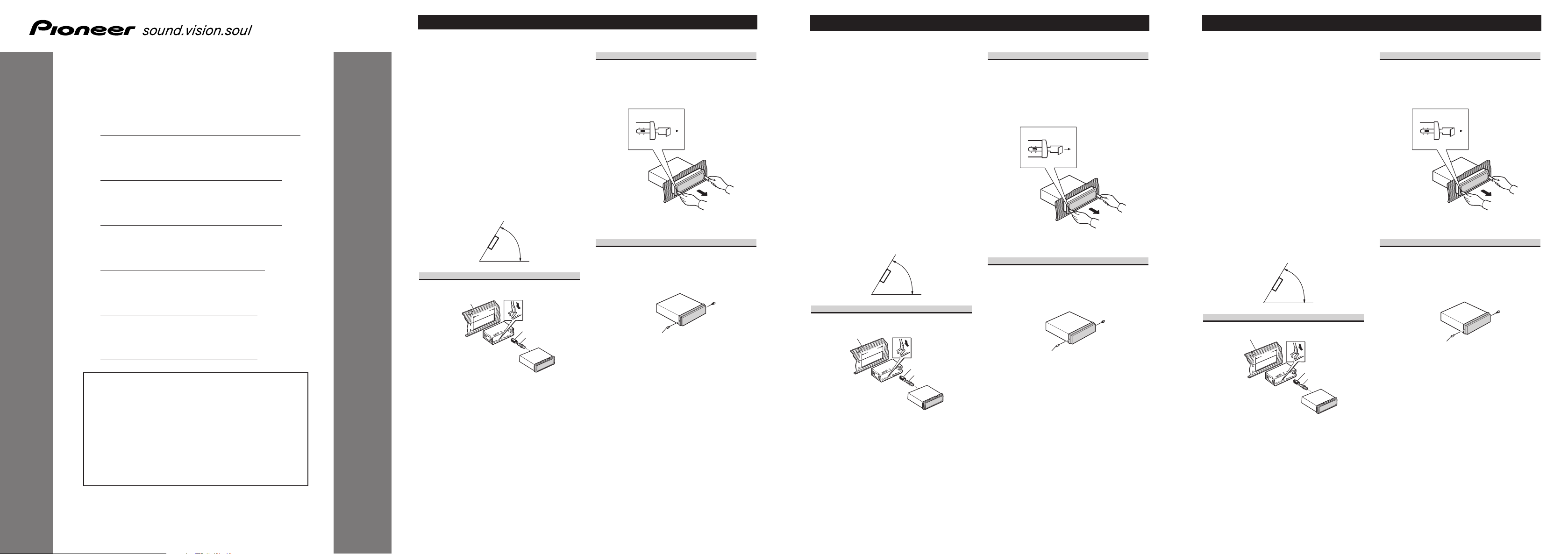
• If installation angle exceeds 60° from horizontal,
the unit might not give its optimum performance.
60°
Installation with the rubber bush
ashboar
After inserting the holder into the dashboard,
then select the appropriate tabs according to the
thickness of the dashboard material and bend
them.
(Install as firmly as possible using the top and
bottom tabs. To secure, bend the tabs 90
degrees.)
Holde
ubber bus
cre
Removing the Unit
Insert the supplied extraction keys into the unit,
as shown in the figure, until they click into place.
Keeping the keys pressed against the sides of the
unit, pull the unit out.
About the fixing screws for the
front panel
If you do not operate the Removing and
Attaching the Front Panel Function, use the supplied fixing screws and fix the front panel to this
unit.
Fixing screw
Nota:
• Antes de finalmente instalar la unidad, conecte el
cableado temporalmente y compruebe que las
conexiones están correctas e que el sistema funciona debidamente.
• Utilice sólo las piezas que se incluyen con esta
unidad para asegurar la instalación adecuada. El
uso de piezas no autorizadas podría causar fallos
de funcionamiento.
• Consulte con su distribuidor si la instalación
requiere del taladro de orificios u otras modificaciones del vehículo.
• Instale la unidad donde no alcance el espacio del
conductor, y donde no pueda dañar a los
pasajeros si sucediera un paro repentino, como
una detención de emergencia.
• El semiconductor láser se dañará si se sobrecalienta, por eso no instale la unidad en un lugar
caliente – por ejemplo, cerca de la salida de un
calefactor.
• Si el ángulo de la instalación excede los 60° del
lado horizontal, la unidad podría no brindar su
óptimo funcionamiento.
60°
Instalación con tope de goma
Tablero de
instrument
Después de insertar el soporte en la tabla de
mandos, luego seleccione las orejetas apropiadas
según el grosor del material de la tabla de mandos y dóblelos.
(Instale lo más firme posible usando las lengüetas superior e inferior. Para fijar, doble las
lengüetas 90 grados.)
Soport
s
Tope de gom
Tornill
Quitado de la unidad
Inserte las herramientas de extracción suministradas en la unidad, como se indica en la figura,
hasta que se enganchen en su positión.
Tire de la unidad mientras mantiene las herramientas presionadas contra los lados de la
unidad.
Sobre los tornillos de fijación del
panel delantero
Si no desea utilizar la función de extracción y
colocación del panel delantero, utilice los tornillos de fijación suministrados y fije el panel
delantero a esta unidad.
Tornillos de fijació
Hinweis:
• Bevor Sie das Gerät endgültig einbauen,
schließen Sie die Kabel provisorisch an und
vergewissern Sie sich, dass alle Anschlüsse stimmen und das System richtig funktioniert.
• Um einwandfreien Einbau zu gewährleisten, sollten nur die mit dem Gerät mitgelieferten Teile
verwendet werden. Bei Verwendung von NichtOriginalteilen kann es zu Funktionsstörungen
kommen.
• Wenden Sie sich an Ihren Fachhändler, wenn
zum Einbau des Geräts Löcher gebohrt oder
andere Veränderungen an Ihrem Auto vorgenommen werden müssen.
• Bauen Sie das Gerät an einer Stelle ein, wo es
den Fahrer nicht behindert und den Beifahrer bei
plötzlichem Bremsen nicht verletzen kann.
• Der Halbleiterlaser wird bei Überhitzung
beschädigt, bauen Sie das Gerät daher nicht an
einer Stelle ein, wo es heiß wird, z.B. nahe einer
Heizungsauslassöffnung.
• Wenn der Einbauwinkel mehr als 60º von der
Horizontalen abweicht, kann es sein, dass das
Gerät nicht optimal arbeitet.
60°
Einbau mit der Gummibuchse
Armaturenbrett
Den Halter in das Armaturenbrett einsetzen, dann
die der Dicke des Armaturenbretts entsprechenden Zungen auswählen und diese biegen.
(Mithilfe der Ansätze, oben und unten, so fest
wie möglich einsetzen. Zur Sicherung werden die
Ansätze 90 Grad gebogen.)
Halt
ummibuchs
chraub
Entnahme des Gerätes
Die mitgelieferten Ausziehschlüssel wie in der
Abbildung gezeigt bis zur Einrastposition in das
Gerät einsetzen. Die Schlüssel gegen die Seiten
des Geräts drücken und das Gerät herausziehen.
Befestigungsschrauben für die
Frontplatte
Wenn Sie die Funktion zum Abnehmen und
Anbringen der Frontplatte nicht verwenden
wollen, so fixieren Sie die Frontplatte mit den
mitgelieferten Befestigungsschrauben an diesem
Gerät.
Befestigungsschraub
Printed in
Imprimé
<URD3875-A> EW
<KSNNX> <05K00000>
f
53
182182
r
R
of
f
D
d
o
53
182182
o
a
Vite
C
o
on
53
182182
t
Bag
o
c
Vi
s
d
Installation <FRANÇAIS>
53
182182
ÑÂ
¸
fl
¸
Installazione <ITALIANO>
Installeren <NEDERLANDS>
ìÒÚ‡Ìӂ͇ <PYCCKàâ>
Remarque:
• Avant d’effectuer l’installation définitive, reliez
provisoirement les appareils entre eux pour vous
assurer qu’ils fonctionnent correctement, individuellement et ensemble.
• Pour obtenir une bonne installation, n’utiliser que
les pièces de l’appareil. L’utilisation de pièces
non prévues risque de causer un mauvais fonctionnement.
• Consulter le concessionnaire le plus proche si
l’installation nécessite le percement de trous ou
toute autre modification du véhicule.
• Installer l’appareil à un endroit où il ne gêne pas
le conducteur et où il ne peut pas blesser les passagers en cas d’arrêt brusque, comme pendant un
arrêt d’urgence.
• Le laser semiconducteur sera endommagé en cas
de réchauffement excessif. Dans ce cas ne pas
installer l’appareil dans un endroit présentant une
température élevée, tel que sortie de chauffage.
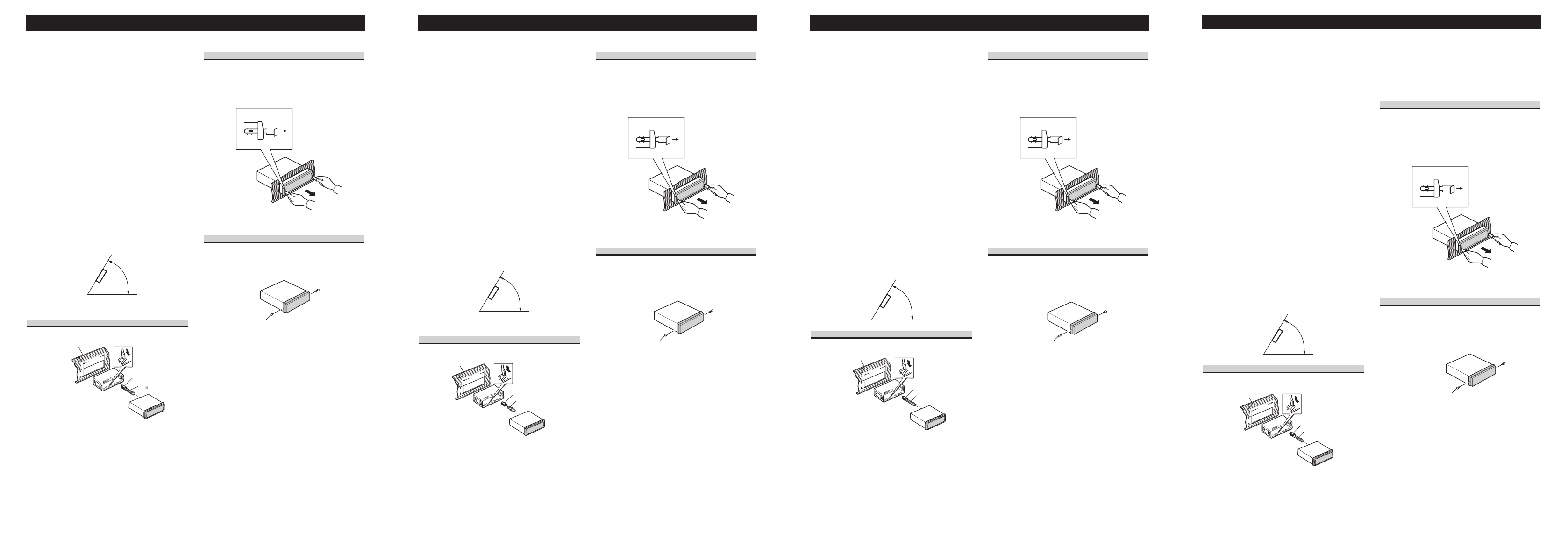
• L’angle de l’installation, ne doit pas dépasser 60°
par rapport à l’horizontale, faute de quoi l’unité ne
fournira pas ses performances optimales.
60°
Installation avec une bague en
caoutchouc
Tableau de bor
Suppor
ca
ue en
utchou
Dépose de l’únite
Insérer les clés d’extraction fournis dans l’unité,
comme indiqué dans la figure, jusqu’à ce qu’elles
s’enclenchent en position. En maintenant ces clés
pressées contre les côtés de l’unité, retirer l’unité.
À propos des vis de fixation de la
face avant
Si vous n’utilisez pas la fonction de dépose et
pose de la face avant, utilisez la vis de fixation
fournie et fixez la face avant à l’appareil.
Vis de fixati
Nota:
• Prima di installare definitivamente l’apparecchio,
collegare temporaneamente i cavi in modo da
verificare che i collegamenti eseguiti siano corretti ed il sistema operi correttamente.
• Per un’installazione appropriata, usare soltanto i
pezzi in dotazione all’apparecchio. L’uso di pezzi
non autorizzati può causare problemi di funzionamento.
• Rivolgersi al più vicino rivenditore se l’installazione richiede la trapanatura di fori o altre
modifiche del veicolo.
• Installare l’apparecchio in un punto in cui esso
non intralci le manovre del conducente e in cui
non possa provocare lesioni ai passeggeri nel
caso dell’arresto improvviso del veicolo, come
nel caso di una frenata d’emergenza.
• Il laser a semiconduttore subisce danni se si surriscalda; pertanto, non installare l’apparecchio in
luoghi esposti al calore, come per esempio nei
pressi della bocca di efflusso dell’impianto di
riscaldamento.
• Se l’angolo di installazione supera i 60° rispetto
alla posizione orizzontale, l’apparecchio potrebbe
non fornire prestazioni ottimali.
60°
Installazione con la boccola di
gomma
ruscott
Support
Boccola di gomm
Estrazione dell’unità
Inserire le chiavette di estrazione in dotazione
nell’apparecchio, come mostrato nella figura,
finché non scattano in posizione. Tenendo le chiavette premute contro i lati dell’apparecchio,
estrarre l’apparecchio.
Viti di fissaggio per il pannello
anteriore
Se non si usa la funzione Rimozione e montaggio
del frontalino, usare le viti di fissaggio in
dotazione per fissare il frontalino su questo
apparecchio.
Vite di fissaggi
Opmerking:
• Voor u het toestel definitief installeert, dient u de
bedrading tijdelijk aan te sluiten om te controleren of alle verbindingen correct zijn en of het
systeem naar behoren functioneert.
• Gebruik voor het installeren uitsluitend de bij het
apparaat geleverde onderdelen. Toepassing van
andere dan de goedgekeurde onderdelen kan leiden tot storing in de werking van het apparaat.
• Raadpleeg uw dichtstbijzijnde dealer als het voor
het installeren van het apparaat nodig blijkt gaten
te boren, of andere wijzigingen aan te brengen
aan de auto.
• Installeer het apparaat op een plaats waar het de
bestuurder niet in de weg kan zitten en waar het
ook bij een noodstop e.d. geen gevaar voor de
inzittenden kan opleveren.
• De halfgeleider-laser in het apparaat is gevoelig
voor beschadiging door oververhitting, dus
installeer het apparaat niet te dicht in de buurt
van de autoverwarming of de warme luchtsroom
daarvan.
• Als u het apparaat onder een al te steile hoek
installeert, d.w.z. meer dan 60° uit het horizontale vlak, zal het niet naar behoren kunnen
werken.
60°
Installatie met de rubber mof
ashboar
Houde
ubber m
Schroe
Verwijderen van het apparaat
Steek de bijgeleverde verwijdersleutels in het
apparaat, zoals in de afbeelding aangegeven, tot
ze op hun plaats vastklikken. Houd de sleutels
tegen de zijkanten van het apparaat aangedrukt
en trek het apparaat naar buiten.
Meer over de bevestigingsschroeven
voor het voorpaneel
Indien u de functie voor Los maken en bevestigen van het voorpaneel niet gebruikt, moet u met
de bijgeleverde bevestigingsschroeven het voorpaneel aan dit apparaat vastzetten.
Bevestigingsschroe
èËϘ‡ÌËfl:
• иВВ‰ УНУМ˜‡ЪВО¸МУИ ЫТЪ‡МУ‚НУИ ЫТЪУИТЪ‚‡
‚ВПВММУ ФУ‰ТУВ‰ЛМЛЪВ ФУ‚У‰‡, ˜ЪУ·˚
Ы·В‰ЛЪ¸Тfl ‚ ЪУП, ˜ЪУ ТУВ‰ЛМВМЛfl ‚˚ФУОМВМ˚
Ф‡‚ЛО¸МУ Л ТЛТЪВП‡ ‡·УЪ‡ВЪ ‰УОКМ˚П
У·‡БУП.
• СОfl Ф‡‚ЛО¸МУИ ЫТЪ‡МУ‚НЛ ТОВ‰ЫВЪ
ФУО¸БУ‚‡Ъ¸Тfl ЪУО¸НУ НУПФУМВМЪ‡ПЛ,
ФУТЪ‡‚ОflВП˚ПЛ Т ЫТЪУИТЪ‚УП.
аТФУО¸БУ‚‡МЛВ МВЫЪ‚ВК‰ВММ˚ı Н
ЛТФУО¸БУ‚‡МЛ˛ НУПФУМВМЪУ‚ ПУКВЪ ФЛ‚ВТЪЛ
Н Т·УflП ‚ ‡·УЪВ ЫТЪУИТЪ‚‡.
• ЦТОЛ ‰Оfl ЫТЪ‡МУ‚НЛ ЪВ·ЫВЪТfl ФУТ‚ВОЛЪ¸
УЪ‚ВТЪЛfl ЛОЛ ПУ‰ЛЩЛˆЛУ‚‡Ъ¸ ‡‚ЪУПУ·ЛО¸
ЛМ˚П У·‡БУП, Т‚flКЛЪВТ¸ Т ·ОЛК‡И¯ЛП
‰ЛОВУП.
• мТЪ‡МУ‚ЛЪВ ЫТЪУИТЪ‚У Ъ‡НЛП У·‡БУП, ˜ЪУ·˚
УМУ МВ ПВ¯‡ОУ ‚У‰ЛЪВО˛ Л МВ ПУ„ОУ
Ъ‡‚ПЛУ‚‡Ъ¸ Ф‡ТТ‡КЛУ‚ ‚ ТОЫ˜‡В ВБНУ„У
ЪУПУКВМЛfl, Н‡Н М‡ФЛПВ ‚ ‡‚‡ЛИМУИ
ТЛЪЫ‡ˆЛЛ.
• иВ„‚ ФУОЫФУ‚У‰МЛНУ‚У„У О‡БВ‡
ФЛ‚У‰ЛЪ Н В„У ФУ‚ВК‰ВМЛ˛, ФУ˝ЪУПЫ МВ
ЫТЪ‡М‡‚ОЛ‚‡ИЪВ ЫТЪУИТЪ‚У ‚ ПВТЪ‡ı,
ФУ‰‚ВКВММ˚ı ‚УБ‰ВИТЪ‚Л˛ ‚˚ТУНУИ
ЪВПФВ‡ЪЫ˚, М‡ФЛПВ, fl‰УП Т ‚˚ФЫТНУП
М‡„В‚‡ЪВОfl.
• ÖÒÎË ÛÒÚ‡ÌÓ‚ËÚ¸ ÛÒÚÓÈÒÚ‚Ó ÔÓ‰ Û„ÎÓÏ ·ÓÎÂÂ
60°, Н‡˜ВТЪ‚У ‡·УЪ˚ ЫТЪУИТЪ‚‡, ‚УБПУКМУ,
МВ ·Ы‰ВЪ УФЪЛП‡О¸М˚П.
60°
мТЪ‡МУ‚Н‡ Т ВБЛМУ‚УИ ‚ЪЫОНУИ
è‰Ìfl
Ô‡ÌÂÎ
ʇÚÂÎ
(мТЪ‡МУ‚ЛЪВ ЫТЪУИТЪ‚У Н‡Н ПУКМУ ФОУЪМВВ
ФЛ ФУПУ˘Л ‚ВıМЛı Л МЛКМЛı ‚˚ТЪЫФУ‚.
лУ„МЛЪВ ‚˚ТЪЫФ˚ ФУ‰ Ы„ОУП 90 „‡‰ЫТУ‚,
˜ЪУ·˚ М‡‰ВКМУ Б‡НВФЛЪ¸ ЫТЪУИТЪ‚У).
쉇ОВМЛВ ЫТЪУИТЪ‚‡
ЗТЪ‡‚¸ЪВ НО˛˜Л ‰Оfl ЛБ‚ОВ˜ВМЛfl, ‚ıУ‰fl˘ЛВ ‚
ФУТЪ‡‚ОflВП˚И НУПФОВНЪ, Н‡Н ФУН‡Б‡МУ М‡
ЛТЫМНВ, Л М‡‰‡‚ЛЪВ М‡ МЛı ‰У ЪВı ФУ, ФУН‡ МВ
ЫТО˚¯ЛЪВ ˘ВО˜УН. З˚ЪflМЛЪВ ЫТЪУИТЪ‚У,
Ы‰ВКЛ‚‡fl В„У НО˛˜‡ПЛ Б‡ ·УНУ‚˚В ТЪУУМ˚.
é ¯ÛÛÔ‡ı ‰Îfl ÙËÍÒ‡ˆËË
ÔÂ͉ÌÂÈ Ô‡ÌÂÎË
EТОЛ МВ ‚˚ МВ УЪТУВ‰ЛМflВЪВ В„ЫОflМУ
ФВВ‰М˛˛ Ф‡МВО¸, ЪУ ВВ ПУКМУ КВТЪНУ
ФЛНВФЛЪ¸ Н УТМУ‚МУПЫ ПУ‰ЫО˛ Т ФУПУ˘¸˛
ФЛО‡„‡ВП˚ı ¯ЫЫФУ‚.
оЛНТЛЫ˛˘ЛИ ¯ЫЫФ
кВБЛМУ‚‡fl ‚ЪЫОН‡
Après avoir introduit le support dans le tableau
de bord, sélectíonnez les languettes appropriées
en fonction de l’épaisseur du matériau du tableau
de bord et courbez-les.
(Assurez le maintien aussi solidement que possible en utilisant les languettes inférieures et
supérieures. Cela fait, courbez les languettes de
90 degrés.)
Dopo aver inserito il supporto nel cruscotto,
selezionare le linguette appropriate a seconda
dello spessore del materiale del cruscotto e piegarle.
(Installare quanto più saldamente possibile servendosi delle linguette superiore e inferiore. Per
fissare, piegare le linguette a 90 gradi.)
Nadat u de houder in het dashboard hebt
geplaatst, kiest u de juiste lipjes voor de dikte
van het dashboard-materiaal en buigt u deze om.
(Plaats zo stevig als mogelijk met gebruik van de
boven- en onderlipjes. Buig de lipjes 90 graden
om te vergrendelen.)
ÇÒÚ‡‚Ë‚ ‰ÂʇÚÂθ ‚ ÔÂÂ‰Ì˛˛ Ô‡ÌÂθ
‡‚ÚÓÏÓ·ËÎfl, ‚˚·ÂËÚ ÔÓ‰ıÓ‰fl˘Ë ‚˚ÒÚÛÔ˚ ‚
ÒÓÓÚ‚ÂÚÒÚ‚ËË Ò ÚÓ΢ËÌÓÈ Ï‡Ú¡· Ô‰ÌÂÈ
Ô‡ÌÂÎË Ë ÒÓ„ÌËÚ Ëı.
 Loading...