

Pioneer CT1270WR Owner’s Manual
STEREO
DOUBLE CASSETTE TAPE DECK
C1 -1270WR
Thank you for buying this Pioneer product,
Please read through these operating instructions so you wilt
know how to operate your model properly, After you have
finished reading the instructions, put them away in a safe
place for future reference,
In some countries or regions, the shape of the power plug and
power outlet may sometimes differ from that shown in the ex-
planatory drawings_ However, the method of connecting and
operating the unit is the same.
WARNI NG: TO PREVENT FIRE OR SHOCK HAZARD.
DO NOT EXPOSE THIS APPLIANCE TO RAIN OR MOISTURE,
IMPORTANT NOTICE
[For U,S. and Canadian models]
The serial number for this equipment is located on the rear
panel Please write this serial number on your enclosed war-
ranty card and keep in a s_cure ares, This is for your security,,
[For Canadian model]
CAUTION: TOPREVENTELECTRICSHOCKDONOT
USE THIS (POLARIZED) PLUG WITH AN EXTENSION CORD.
RECEPTACLE OR OTHER OUTLET UNI3i[SS THE BLADES CAN
BE FULLY INSERTED TO PREVENT BLAIYkEEXPOSURE
ATTENTION: PourPREVENmRLESCHOCSELEC-
TRIQUESNEPASUT_UBERCETTEFICHEPOLARISEEAWC
UN PROLONGATEUR UNE PRISE DE COURANT OU UNE
AUTRE SORTIE DE COURANT, SAUF SI LES LAMES PEUVENT
ETRE tNSEREES A FOND SANS EN LA1SSER AUCUNE PARTIE
A DECOUVERT
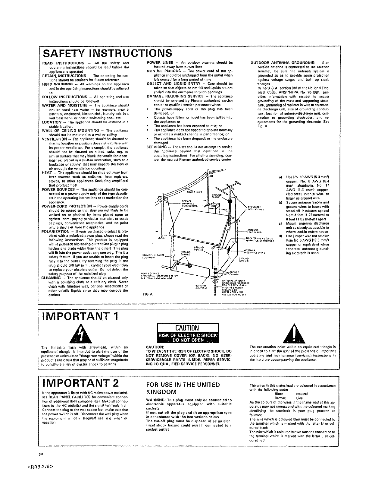
LINE VOLTAGE SELECTOR SWITCH
Only multi-voltage models are provided with this
switch, U_S. Canadian, European, U.K,,, and Australian
models are not provided with this switch.
The line voltage selector switch is on the rear panel, Before
your model is shTpped from the factory, this switch is set to
the power requirements of the destination Check that it is set
properly before plugging the power cord into the AC outlet. If
the voltage is not properly set or if you move to an area where
the voltage requirements differ, adjust the selector switch as
follows
1 Disconnect the power cord,
2_ Use a medium-size screwdriver.
3. Insert the screwdriver into the groove on the voltage selec-
tor, and adjust so that the tip of the arrow points to the
voltage value of your area,
Medium-size screwdriver
"This product is manufactured to comply with the radio in- I
Iterference requirements of EEC Directive 76/889/EEC and
[82/4.99/EECo "
PIONEER"
SAFETY INSTRUCTIONS
READ INSTRUCTIONS - All the salary and
operating in_l/UCltons shotted be toad befolo the
app_o is opetal_d
RETAIN._ INSTRUCTIONS - The opetating _i_uc
tion.__houId be t0ta_ned for lutur_ toferenct_
HEED WARNING -- All warnings o_ lbe appliance
and in [he _p,_tlng in_lluctians _bould b_ adhered
Io,
beLLOW iNSTRUCTIONS - Al! operating _nd use
in_{ruc_ions shQuId be Iottow0d
WATER AND MOISTURE - Th_ appliance sho_d
not be u._d _r w_lt_t - fo_" 0xamp_, nea_
bathlub, w_shbowt, kitchen s_nk, I_undry luh _ a
W_! basement, or n_t _ _;wimm_n_ poo_ _c
LOCATION _ The _ppli_nca should be ins{a_10d _t_
stable Iocat_n.
WALL OR CEIUNG MOUNTING _ Th0 ap_ce
_hou_d riot be mrJ_ttt_d to a wa_l o_ ce_ng
VENTILATION - The appliance shouid besiluai_d so
tha_ i_ rotation o_ poshlon does nD_ in_de_e wi_h
its proper wn_ilalion. For example, the appli,_nce
r.h_uld =lot be situoled or_ a bed, _of_ _ug, or
s_m_r _trf_co that may b_ck th0 vent _'_ltionopen ¸¸
in_si or, _ced _ a bui_l,_n tn_ta,allo_, such a_ a
bookc_ o_ _:_bi_et Iha{ may Impede the flow of
air through th_ ventilation openings,
HEAT -- Th_ appliance should ba _tu_ted _w_y &am
ho_ so'Jfc_5 _uch a_ fsd_atots, heel _e_i_,le;_,,
_loves, or othc_"_ppl_a_ca_ ltn¢lud_g ampti{i_t
_ha_produce heal
POWER SOUI_CE_; - The appliance should b_ con-
nectad to a pow_r supply _nly of _ho type d_sc_ib_
od _n _h_operating Insttuclions o__lsmarked on the
appliance,
POWERCORD PROTECTION - Powe_ _pp_ycord_
should he _outed _o that they ate not tlke_y to be
w_tk_d o_ or p_n_:h_d by hem_ p_aced upon o_
against Ihom, p0y_n_ partlcula_ att_.*n{ion t_ coldr,
at plugs, convo_,_once ;_c_ptacl_,. and _ba pain1
wh_ro Ihoy exi_ f_om th0 appliance
POLARIZATION -- tf your purchased producl Is p_o-
vid_d w_lh apolarized power plug, p_oa_e_o_d the
t_t_owing insltUct_ons This producl is _quipp_d
wiih a pola6zed alternating current llne plug I_ phtg
having one blade wider than _ho o_h_rl This plug
will fil in_o _ba power outl_t only one way, Tb_ i_ a
_a|ety foaluto II you ale una_ to In_0_t th_ bhlg
fully into th_ out!0t t_y revelling th_ p_ug ff tile
plug should slill _il t_ fit, co,tact your eI_¢lticlan
salary p_rp_e of the p_lati;_ed p_u0
CLEANING _ ThE appliance should b_ cleaned only
with a polishing cloth or a soil dw c_oI!l Never
clean with turni_Ltto wax, b_r_zino, in_0cticid_s or
other v_atito I_q_td_ _inco th0y m_y co_rodo the
ci_binol
POWER LINES _ An outdom" antenna should ba
NONUSE PERIODS -- The power cord o_ the ap-
OBJECT AND LIQUID ENTRY _ C_to should ba
DAMAGE REQUIRING SERVICE - Tba apptlanco
* The powers_,tbply cord at _h_ pIug has bo_n
" Objects have falcon or _iquld has been spilled into
• Tbo appllancohas been Exposed to faln;or
• The appliancedoes not _ppE_r to opa¢_tonolmaIIy
• Th_ appliance hits been dropped; or tile enclosure
SERVICING - Th_ user should n_t atlempt tO s_iCO
Ioca=ed _way from power I_nes
pliance _ho_Id _ unplugged from the outl0t when
lah _nus0d fat a _n_ period of lime
taken SOthat obiects do not fa_land t_qulds are not
spifled Into Ihe enctosuro through openlng_
sbo_d be se_ic_d by Piono_ authorizedsO.ice
c_n_ el qualff_dserv_o pelsonne] when;
damaged; or
the appliance; or
O_exhlhI_5 a m_kod chB_ge it_ p0t_ot_a_c_; or
damaged
the appliance b_yond Itlatdas_tlbe_din the
operating inslruc_ions re= allothe_ s_vlclng,co_,
tacl _he nearest Pi_noe_ authorized se_'vlcoCenter
OUTDOOR ANTENNA GROUNDING -- II on
o_tsldoanlenna isconne_led to thaantenna
tE_min_L be sure _ho antenna system is
_lound0d so as to provld_ some protection
_g_inst vohoge sulgos and bu_tt up static
-ch_g_s
In lhoU S A section B_Oof the Nattort_l E_a
Ideal Co_a, ANS_/NFPA No 70-_984, pie
rides infotmal]o_l v;ith respect tO proper
grounding Of th_ mast and suppo;tin o$tfuc
IU_a, g_ound_ng o! thr_ _ad in wing to ar_an_en,
na dlschar_E unh, size of grounding conduc
tors_ locallon _f anlenna.d_scP_,rgo _n_t, co+3,
_clion to glou_dlng _t¢cttodes, arid t_'
qu_l_mr:ilt5 fat Iho glound_ng _l_clfod_ SO0
Fig A
a) U$eNo IOAWG 153mm:l
copper. No. B AWG (B,4
mm _) aluminum, NO t7
AWG II.O mm_t _opp0r
c_d steel, bronze who o_
_._ger a_ g_o_nd wi_o.
hi Seculo antenna_ead-_n and
ground wires to hous_ with
stand.oR insulatOrS _paced
f;am 4 fe_t II 22 m_letst 1o
6 teat {f 83 m0t_t_I ap_n
ct Mount arttartna dlschsrgo
unh as c_o_elyas possible to
where _a_d.ln enters ho_e
df Us_lumpor wiro_ot _ma_0t
than No 6 AWG |t3 3 mm _I
copper or equivalent whet_
s_p_rato tttHa_t_t_glout_d_
tn_ e_e_ttod_ i_ u_d
IMPORTANT 1
The li_]htnlng flash with arrowhead, w}thln on
equ_lato_aI tllangle, _s intended to ai_l _h_ user of th_
pm_anc_ ol un_nsUlalad "dLtngotou_ volt,go ¸_whhin th_
product_ enc_or_u_athat may be of suIficlent m_g_itud_
to constlt_tla a risk of olectric _ho_k to pa_son_,
IMPORTANT 2
tf tho apparatus is #ittad with AC mains powor outlet(s)
see REAR PANEL FACILiTiES _ convenien_ connec-
tion of additlonal Ht-FI componentlsI Make all connie-
lions Io the AC o_let(sI and the signal terminals Iirs_
Connect the plug to the w_ll _o¢_0t lasl. _ka _u;e th_
th_ power switch is off, Di_conn0ct the wa_ p_g when
the e_ipm_n_ _s _r_l ir_ be,_bd u_a e g when on
vac_ttlott
<RRB.276>
CAUTION
CAUTION:
TO PREVENT THE R!SK OF ELECTRIC SHOCK, 00
NOT REMOVE COVER fOR BACKL NO USER-
SERVICEABLE PARTS INSIDE. REFER SERVIC-
iNG TO QUALIFIED SERVICE PERSONNEL
FOR USE IN THE UNITED
KINGDOM
WARNING: This plug m_st o.ly be connected tr_
aI_cltonte appEratus equipped with =ultablo
sockat_
t! not. cut off the ptug and fit _n appropriate typ_
_n accordance with the instructions below
The c_t_off plug mu_t be disposed of a_ on aide,
trlcal shoc_ hazard could exist if connected t_ a
soc_t o_ttet
The exclamation poit_twithin an equi_=tetol tti_tng_ois
inle_d0d to aterl the u_r el that pto_enc0 el important
opei_t_ng and maintenance lsorvlclngl _._tluction_ _n
the literature _ccompany{ng the appli_nc_
The wires in this m_ins le_dare co_ou;ed in Dccoldance
with the following code:
As the co[ou_s of the wires in th_ mains read of thisap,
paralus m_y not corre.'_pondwith the colou_ad ma_klng
_dentifying the le_mlnal=- _n your p_ug p_oceed as
follows:
The wirrt which iScolourad blue m_st bo connected to
the tat_h_alwhich i_ma_ked with th0 I_tler N at COl
outed b_ack
The wife wh}ch isCotou_adbrown must b_ connected tn
th_ termin_l which i_maTked with _h_ _etler L or co_
outed _od
Slus: Neutral
Biown_ Live
CONTENTS
Features ................................................................. 3
Preparations and Connections ....................................... 3
Front Panel Facilities ........................................... 4
How to Handle Cassette Tapes ........................ 7
Noise Reduction System ..................................... 7
Recording .................................................................... 8
Playback ...................................................... 9
Relay Playback ................................................. 10
Tape Copying ....................................................... 12
Recording and Playback Using Audio Timer ............ 14
Maintenance ........................................... 16
Troubleshooting ............................................. 17
Specifications .......................................... 20
FEATURES
• Double deck equipped with auto reverse mechanism
(record/playback deck+ exclusive playback deck)
operated by soft-push button,
• Dolby B and C Noise Reduction
• Normal and High-Speed Dubbing Functions
m Relay Play for Extended Playback
o Timer Stand-by Functions
• Music Scan
PREPARATIONS AND CONNECTIONS
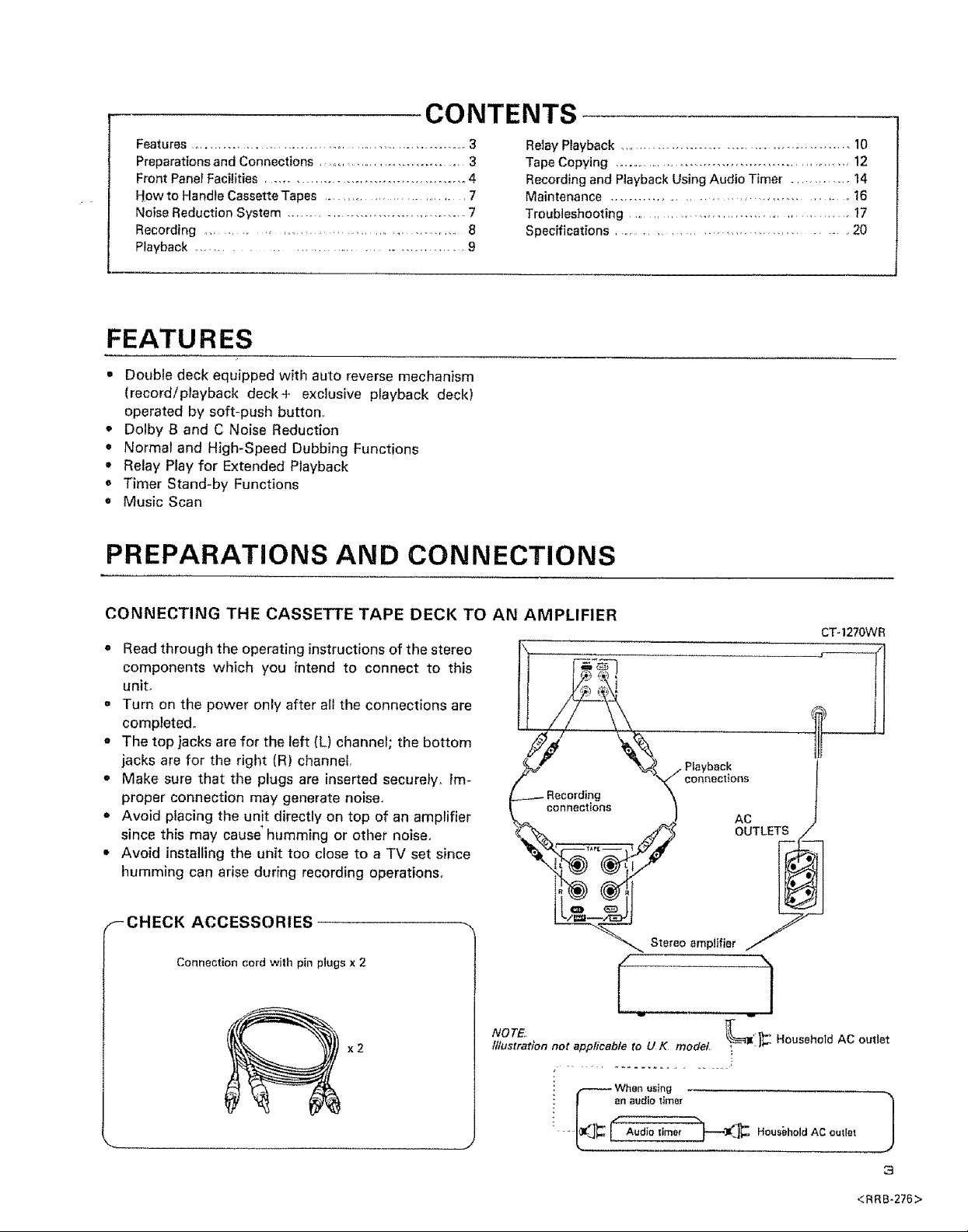
CONNECTING THE CASSETTE TAPE DECK TO AN AMPLIFIER
,, Read through the operating instructions of the stereo
components which you intend to connect to this
unit.
• Turn on the power only after all the connections are
completed.
o The top jacks are for the left (L) channel; the bottom
jacks are for the right (R) channel,
• Make sure that the plugs are inserted securely. Im-
proper connection may generate noise.
• Avoid placing the unit directly on top of an amplifier
since this may cause _humming or other noise.
• Avoid installing the unit too close to a TV set since
humming can arise during recording operations.
k connections ] AC J
_'_ ,_ OUTLETS/
,#;J
I- CHECK ACCESSORIES
Connection cord with pin plugs x 2
NOTE: +_,,
x2
lllustratlon not appflcabteto U K model -I_" HouseholdAC outlet
.......................... i
CT-127OWR
s,o,ooomp,*ior
-- When using
an audio dmer
, , J
J
3
<RRB.276>
FRONT PANEL FACILITIES
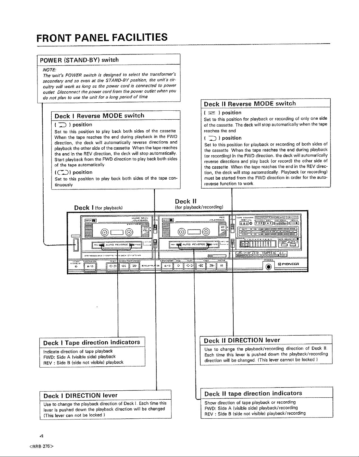
POWE R (STAND-BY) switch
NOTE:
The "unit's POWER switch is designed to select the transformer's
secondary and so even at the STAND-BY position, the unit's cir-
sultry will work as long as the power cord is connected to power
outlet Dtsconnect the power cord from the power outlet when you
do not ptan to use ttre unit for a tong period of time
Deck I Reverse MODE switch
( "_ } position
Set to this position to pfay back both s_des of the cassette
When the tape reaches the and dudng playback in the FWD
direction, the deck will automatically reverse directions and
playback the other side of the cassette When the tape reaches
the end in the REV direction, the deck will stop automatically
Start playback from the FWD direction to play back both sides
of the tape automatically
(_'.._) position
Set to this positron to play back both sides of the tape con-
tinuously
Deck I (for playback) (for playback/recording)
iN 11 M,H,,= ....
Deck II Reverse MODE switch
( z ) position
Set to this position for playback or recording of oniy one side
of the cassette The deck wit_stop automatically when the 1ape
reaches the end
( _ ) position
Set to this position for playback or recording of both sides of
the cassette When the tape reaches the end during playback
(or recording} in the FWD direction, the deck will automat_cafly
reverse directions and play back (or record) the other side of
the cassette, When the tape reaches the end in the REV direc-
tion, the deck will stop automatically, Playback (or recording)
must be started from the FWD direction in order for the auto-
reverse function to work
Deck II
i ......'=111 .......... : .....
/Tape direction indi__cators
direction of tape piayback
ida A (visib(e side) pJayback
ida B (side not visible} playback
Use to change the playback direction of Deck i Each time this
lever is pushed down the playback direction will be changed
I Deck I DIRECTION lever
(This lever can not be locked )
Deck I! DIRECTION lever
Use to change the playback/recording direction of Deck fl,
Each time th(s tever is pushed down the playback/recordlng
direction wilt be changed (This lever cannot be locked )
Deck II tape direction indicators
Show direction of tape playback or recording
FWD: Side A (visible side} playback/reco_'ding
REV : Side B (side not v_sib_e}playback/recording
4-
<RRB.276>
FRONT PANEL FACILITIES
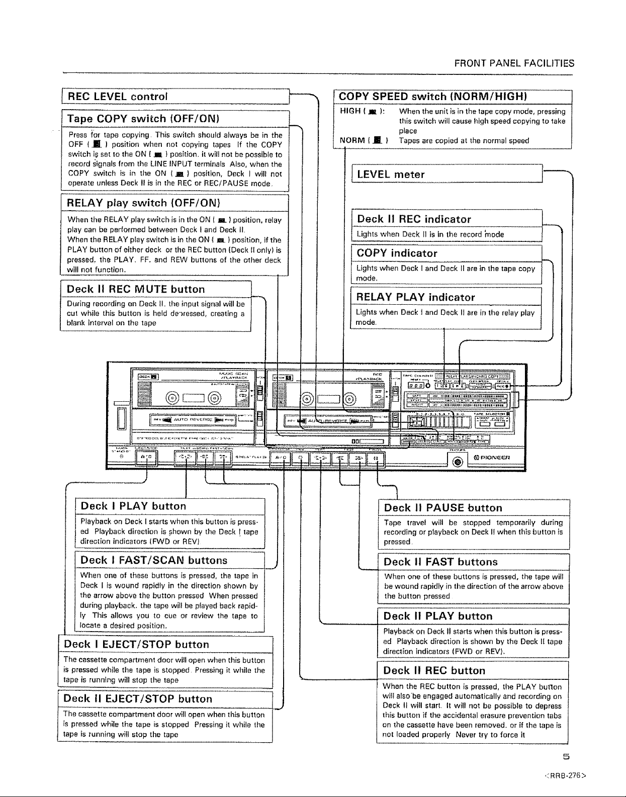
REC LEVEL control
Tape COPY switch (OFF/ON)
Press f'or tape copying This switch should always be in the
OFF (HE) position when not copying tapes If the COPY
switch i_ set to the ON ( m ) position, it wifl not be possible to
record signals from the LINE INPUT terminals Also, when the
COPY switch is in the ON (JIM) position, Deck I wil] not
operate unless Deck 1_is in ti_e REC or RECiPAUSE mode.
RELAY play switch (OFF/ON)
When the RELAY play switch is in the ON ( _. ) position, relay
play can be performed between Deck I and Deck I1
When the RELAY play switch is in the ON ( m ) position, if the
PLAY button of either deck or timeREC button (Deck 11only) is
pressed, the PLAY. FF. and REW buttons of the other deck
will not function.
Deck II REC MUTE button ___
During recording on Deck H. the input signal will be r
cut whiie this button is held de'_ressed, creating a l
blank interval on the tape
3 D.........
COPY SPEED switch (NORM/HIGH)
HIGH ( _ ): When the unit }s in the tape copy mode, pressing
this switch will cause high speed copying to take
NORM ( .mE } Tapes are copied at the normal speed
place
LEVEL meter ]'----_
Deck I1REC indicator L_
Lights when Deck II is in the record _node
Lights when Deck I and Deck II are in the tape copy
COPY indicator
mode.
RELAY PLAY indicator
Lights when Deck i and Deck 1] are in the rainy play
mode
if
_J j L_L_
, Deck I PLAY button j
Playback on Deck I starts when this button is press_
ed Playback direction is shown by the Deck . tape
direction indicators (FWD or REV)
Deck 1 FAST/SCAN buttons ./_._
When one of these buttons is pressed, the tape in
Deck I is wound rapidly in the direction simewn by
the arrow above the button pressed When pressed
during playback, the tape wil! be p_ayed back rapid-
ly This al]ows you to cue or review the tape to
locate a desired position.
The cassette compartment doer wilt open when this button
is pressed while the tape is stopped Pressing it while the
f Deck I EJECT/STOP button
tape is running will stop the tape
Deck 11EJECT/STOP button 1
The cassette compartment door wifl open when this button
is pressed while the tape is stopped Pressing it while the
tape is running witl stop time tape
J
I
L__
Deck It PAUSE button
Tape trave_ wilt be stopped temporarily during I
recording or playback on Deck I! when this button is I
pressed, J
I Deck !1 FAST buttons
When one of these buttons is pressed, the tape witI
be wound rapidly in the direction of the arrow above
[
the button pressed
Deck II PLAY button
PEaybaek on Deck 11starts when this button _spress-
ed Playback direction is shown by the Deck II tape
direction indicators (FWD or REV).
Deck II REC button
When the REC button is pressed, the PLAY but'ton
will also'be engaged automatically and recording on
Deck II will start It will not be possible to depress
this button if the accidental erasure prevention tabs
on the cassette have been removed, or if the tape is
not loaded properly Never try to force it
5
<RRB-276>
FRONT PANEL FACILITIES
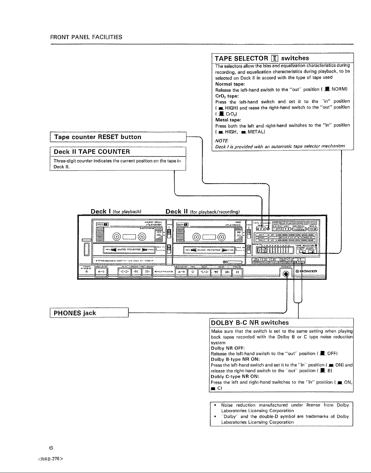
Tape counter RESET button
Deck tl TAPE COUNTER 1
Three-digit counter indicates the current position on the tape ir_
Deck II,
?
TAPE SELECTOR [] switches
The selectors allow the bias and equalization characteristics during '
recording, and equalization characteristics during playback, to be
selected on Deck I1 in accord with the type of tape used
Normal tape:
Release the left-hand switch to the "out" position ( JU NORM)
CrOz tape:
Press the left-hand switch and set it to the "in" position
( I_ HIGH) and tease the right-hand switch to the "out" position
I _ CrO_)
Metal tape:
Press both the left and right-hand switches to the "in" position
( _ HIGH, n_ METAL)
NOTE
Deck 1 is provided with an automatic tape selector mechanism
r
3
Deck I (for ptayback! . Deck 11(for /
PHONES jack !'
D-OLBY B-C NR switches
Make sure that the switch is set to the same setting when playing
back tapes recorded with the Dolby B or C type noise reduction
system
Dotby NR OFF;
Refease the left-hand switch to the "out" position ( __ OFF)
Dolby B-type NR ON:
Press the left*hand switch and set it to the "in" position ( _ ON) and
release the right-hand switch to the "out" position ( JR B)
Dobty C-type NR ON;
Press the left and right-hand switches to the "in" position I _ ON,
_C)
<RR8-276>
Laboratories Licensing Corporation
"Dolby" and the double-D symbol are trademarks of Dolby
I i Noise reduction manufactured under license from Dolby
Laboratories Licensing Corporation
 Loading...