

PIONEER ELECTRONIC CORPORATION 4-1, Meguro 1-Chome, Meguro-ku, Tokyo 153-8654, Japan
PIONEER ELECTRONICS SERVICE INC. P.O.Box 1760, Long Beach, CA 90801-1760 U.S.A.
PIONEER ELECTRONIC [EUROPE] N.V. Haven 1087 Keetberglaan 1, 9120 Melsele, Belgium
PIONEER ELECTRONICS ASIACENTRE PTE.LTD. 253 Alexandra Road, #04-01, Singapore 159936
C PIONEER ELECTRONIC CORPORATION 1999
K-ZZY. FEB. 1999 Printed in Japan
ORDER NO.
CRT2317
MULTI-CD COMPACT DISC PLAYER
CDX-P656 X1N/UC
CONTENTS
1. SAFETY INFORMATION ............................................3
2. EXPLODED VIEWS AND PARTS LIST.......................4
3. SCHEMATIC DIAGRAM ...........................................12
4. PCB CONNECTION DIAGRAM ................................20
5. ELECTRICAL PARTS LIST ........................................26
6. ADJUSTMENT..........................................................29
7. GENERAL INFORMATION .......................................35
7.1 IC .........................................................................35
7.2 DIAGNOSIS ........................................................40
7.2.1 DISASSEMBLY .........................................40
7.2.2 TEST MODE..............................................42
7.3 BLOCK DIAGRAM ..............................................48
8. OPERATIONS AND SPECIFICATIONS.....................50
- See the separate manual CX-892(CRT2356) for the CD mechanism description, disassembly and circuit
description.
- The CD mechanism employed in this model is one of C7 series.
CDX-P656/X1N/UC
CDX-P25 X1N/EW
2
CDX-P656,P25
- CD Player Service Precautions
1. For pickup unit(CXX1285) handling, please refer
to"Disassembly"(See page 40). During replacement,
handling precautions shall be taken to prevent an
electrostatic discharge(protection by a short pin).
2. During disassembly, be sure to turn the power off
since an internal IC might be destroyed when a connector is plugged or unplugged.
3. Please checking the grating after changing the pickup
unit(see page 29) since these screws protects the
mechanism during transport, be sure to affix it when
it is transported for repair, etc.
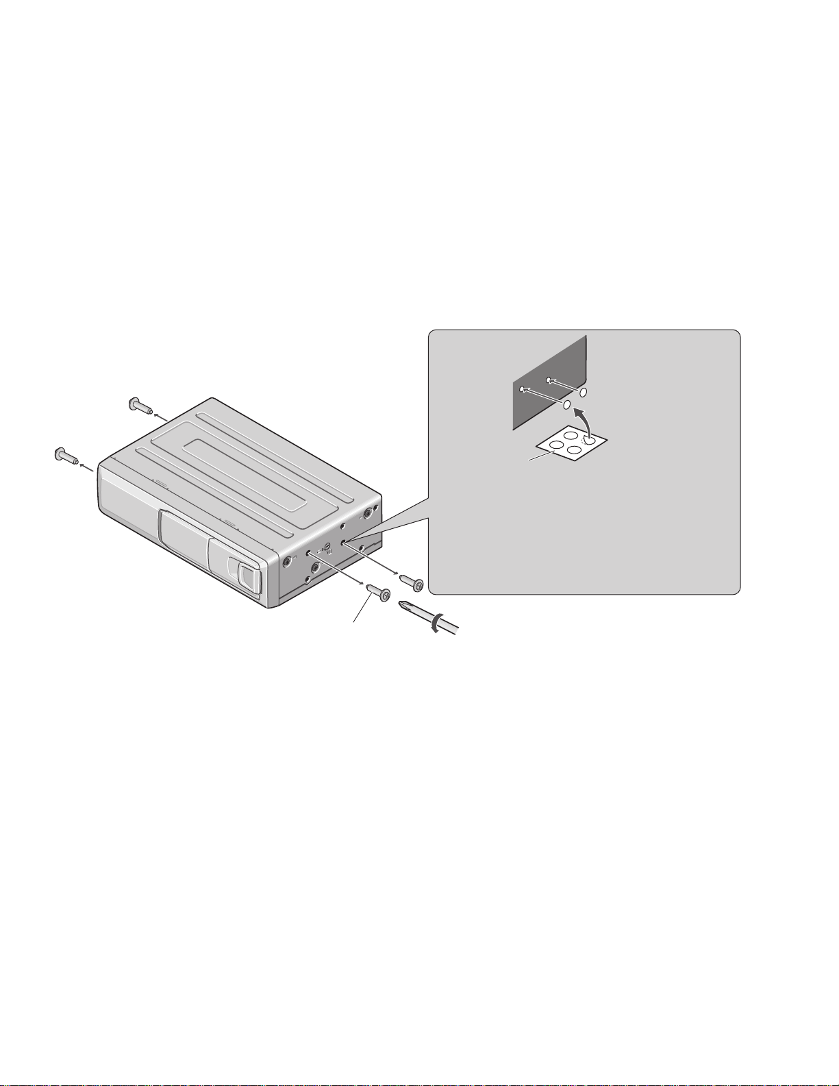
Transport screw
Attach to the original position before transporting the set.
Seal
After removing the transport screw, cover the hole
with the supplied seal.
A transport screw has been attached to the set in order to protect it
during transportation. After removing the transport screw, cover the
hole with the supplied seal. Be sure to remove the transport screw
before mounting the set. The removed transport screw should be
retained in the accessory bag for use the next time the set is transported.
Transportation of multi-CD Player
3
CDX-P656,P25
1. SAFETY INFORMATION
1.1 CDX-P656/X1N/UC
CAUTION
This service manual is intended for qualified service technicians; it is not meant for the casual do-it-yourselfer.
Qualified technicians have the necessary test equipment and tools, and have been trained to properly and safely repair
complex products such as those covered by this manual.
Improperly performed repairs can adversely affect the safety and reliability of the product and may void the warranty.
If you are not qualified to perform the repair of this product properly and safely; you should not risk trying to do so
and refer the repair to a qualified service technician.
W
ARNING
This product contains lead in solder and certain electrical parts contain chemicals which are known to the state of
California to cause cancer, birth defects or other reproductive harm.
Health & Safety Code Section 25249.6 - Proposition 65
1.2 CDX-P25/X1N/EW
1. Safety Precautions for those who Service this Unit.
• Follow the adjustment steps (see pages 29 through 34)in the service manual when servicing this unit. When checking or adjusting the emitting power of the laser diode exercise caution in order to get safe, reliable results.
Caution:
1. During repair or tests, minimum distance of 13cm from the focus lens must be kept.
2. During repair or tests, do not view laser beam for 10 seconds or longer.
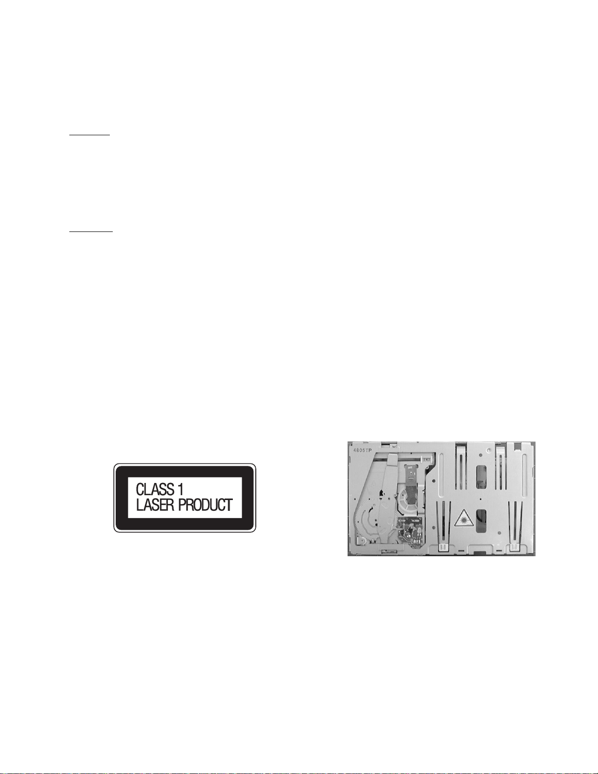
2. A “CLASS 1 LASER PRODUCT” label is affixed to the
rear of the player.
3. The triangular label is attached to the mechanism
unit frame.
4. Specifications of Laser Diode
Specifications of laser radiation fields to which human access is possible during service.
Wavelength = 800 nanometers
4
CDX-P656,P25
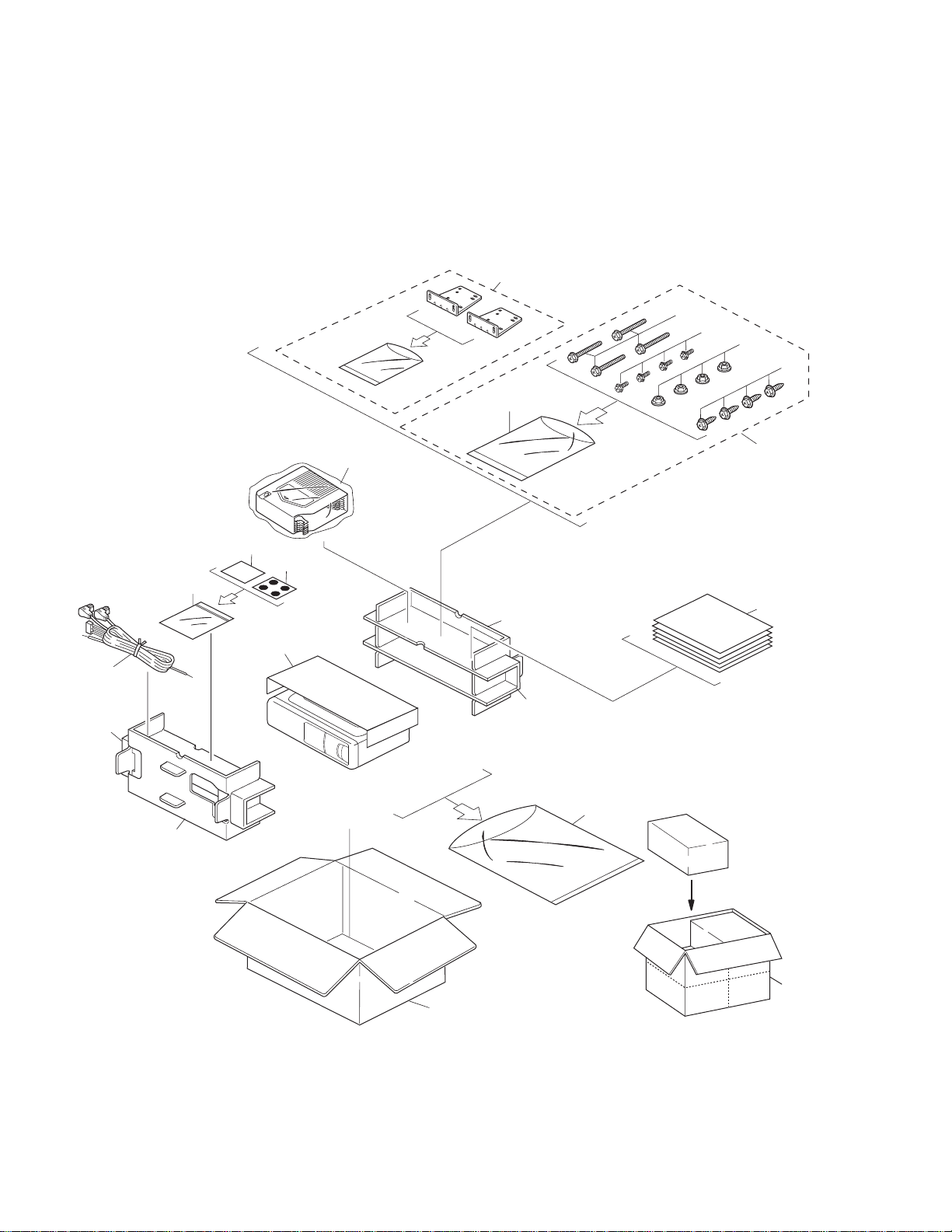
2. EXPLODED VIEWS AND PARTS LIST
2.1 PACKING
12
11
11
12
8
9
15
19
10
7
13
5
4
3
1
6
2
14
20
21
16
5
CDX-P656,P25
Part No.
Mark No. Description CDX-P656/X1N/UC CDX-P25/X1N/EW
1 Screw Assy CEA1962 CEA1962
2 Screw CBA1295 CBA1295
* 3 Polyethylene Sheet CNM5158 CNM5158
4 Screw HMB60P500FMC HMB60P500FMC
5 Screw HMF40P080FZK HMF40P080FZK
6 Nut NF60FMC NF60FMC
* 7 Polyethylene Bag CEG1099 CEG1099
8 Polyethylene Bag CEG1185 CEG1042
9 Carton CHG3713 CHG3715
10 Contain Box CHL3713 CHL3715
11 Protector CHP2133 CHP2133
12 Protector CHP2134 CHP2134
13 Seal CNM5599 CNM5599
14-1 Owner’s Manual CRD2887 CRD2893
14-2 Owner’s Manual Not used CRD2894
* 14-3 Warranty Card CRY1070 CRY1087
* 14-4 Caution Card CRP1201 CRP1203
* 14-5 Caution Card CRP1205 CRP1205
15 Magazine Assy CXB4027 CXB4027
16 Angle Assy CXB3591 CXB3591
17 •••••
18 •••••
19 Cord CDE5831 CDE5830
* 20 Caution Card CRP1090 CRP1090
* 21 Caution Card CRP1195 CRP1195
- Owner’s Manual
Model Part No. Language
CDX-P656/X1N/UC CRD2887 English, French
CDX-P25/X1N/EW CRD2893 English, Italian, French
CRD2894 German, Dutch, Spanish
- PACKING SECTION PARTS LIST
NOTE:
- Parts marked by “*”are generally unavailable because they are not in our Master Spare Parts List.
- Screws adjacent to
∇ mark on the product are used for disassembly.
6
CDX-P656,P25
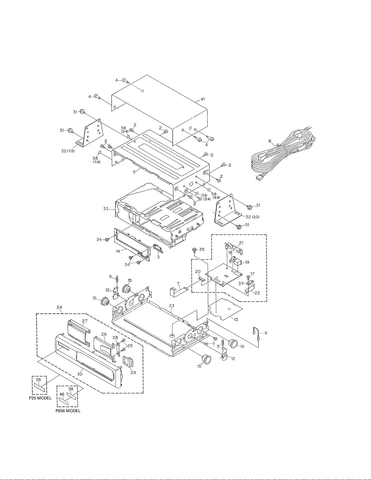
2.2 EXTERIOR
7
CDX-P656,P25
1 Screw BMZ26P040FMC
2 Screw BMZ30P040FZK
3 Button CAC4632
4 Screw CBA1460
5 Spring CBH1859
6 Connector CDE5525
7 Connector CDE5783
8 Cord
See Contrast table(2)
9 •••••
10 •••••
11 Upper Case CNB2431
12 Arm CNC8058
13 Insulator CNM6074
14 Panel CNS5216
15 Damper CNV5591
16 Power Unit CWX2299
17 Screw BMZ26P060FMC
18 Plug(CN901) CKS-460
19 Connector(CN921) CKS3407
20 Connector(CN911) CKS4072
21 Holder CNC8055
22 Holder CNC8056
23 Lower Case Unit CXB3395
24 Grille Unit
See Contrast table(2)
25 Screw BPZ20P080FMC
26 Door
See Contrast table(2)
27 Door See Contrast table(2)
28 Holder CNC8139
29 Lever
See Contrast table(2)
30 Grille See Contrast table(2)
31 Screw HMF40P080FZK
32 Angle Assy CXB3591
33 CD Mechanism Module
See Contrast table(2)
34 Screw IMS20P035FZK
35 Screw IMS26P040FMC
36 Sheet
See Contrast table(2)
37 Transistor(Q910) 2SD2396
38 Seal CNM5599
* 39 Double Faced Tape
See Contrast table(2)
* 40 Batch See Contrast table(2)
* 41 Caution Card CRP1195
(1) EXTERIOR SECTION PARTS LIST
Mark No. Description Part No. Mark No. Description Part No.
Part No.
Mark No. Symbol and Description CDX-P656/X1N/UC CDX-P25/X1N/EW
8 Cord CDE5831 CDE5830
24 Grille Unit CXB4374 CXB4383
26 Door CAT2045 CAT2013
27 Door CAT2046 CAT2014
29 Lever CNS5392 CNS5391
30 Grille CNS5290 CNS5292
33 CD Mechanism Module CXK4805 CXK4800
36 Sheet Not used CAH1682
* 39 Double Faced Tape CNM6211 Not used
* 40 Batch CAH1680 Not used
(2) CONTRAST TABLE
CDX-P656/X1N/UC and CDX-P25/X1N/EW are constructed the same except for the following:
8
CDX-P656,P25
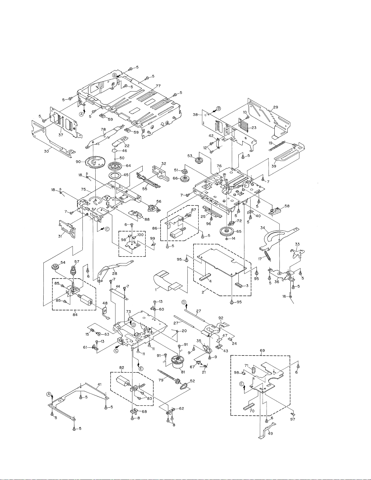
2.3 CD MECHANISM MODULE

9
CDX-P656,P25
1 Connector CDE6069
2 CD Core Unit(C7)
See Contrast table(2)
3 Connector(CN701) CKS1953
4 Connector(CN101) CKS2272
5 Screw BMZ20P025FMC
6 Screw CBA1037
7 Screw CBA1041
8 Screw CBA1176
9 Screw CBA1362
10 Screw CBA1387
11 Screw CBA1470
12 Screw CBA1476
13 Screw CBA1486
14 Washer CBF1038
15 Spring CBH2172
16 Spring CBH2173
17 Spring CBH2174
18 Spring CBH2175
19 Spring CBH2285
20 Spring CBH2177
21 Spring CBH2178
22 Spring CBL1390
23 Spring CBL1392
24 Short Pin CBL1239
25 Volume(VR801) CCW1023
26 •••••
27 Shaft CLA3304
28 Arm CNC7901
29 Lever CNC7902
30 Lever CNC7904
31 Lever CNC7905
32 Lever CNC7906
33 Arm CNC7908
34 Arm CNC7909
35 Holder CNC7911
36 Holder CNC7912
37 Frame CNC7917
38 Frame CNC7918
39 Lever CNC7919
40 Stopper CNC7920
41 Frame CNC7921
42 Bracket CNC8354
43 Plate CNC8375
44 Cover CNC8434
45 Sheet CNM6009
46 Spacer CNM6146
47 Sheet CNM6296
48 PCB CNP5227
49 PCB CNP5228
50 Ball CNR1189
51 Gear CNR1531
52 Belt CNT1086
53 Gear CNV5472
54 Gear CNV5473
55 Rail CNV5474
56 Lever CNV5475
57 Gear CNV5477
58 Arm CNV5478
59 Holder CNV5480
60 Guide CNV5481
61 Guide CNV5482
62 Holder CNV5483
63 Holder CNV5484
64 Clamper CNV5485
65 Gear CNV5486
66 Gear CNV5562
67 Holder CNV5563
68 Lighting Conductor CNV5785
69 Mechanism PCB CWX2303
70 Connector(CN801) CKS1965
71 Connector(CN802) CKS3486
72 Damper Unit CXA7714
73 Chassis Unit CXB2850
74 •••••
75 Chassis Unit CXB2851
76 Magazine Holder Unit CXB2853
77 Frame Unit CXB4426
78 Arm Unit CXB2855
79 Screw Unit CXB2857
80 •••••
81
Motor Unit(M851)(SPINDLE) CXB3003
82
Motor Unit(M854)(CARRIAGE) CXB3004
83 Screw JFZ20P025FMC
84 Motor Unit(M853)(TRAY) CXB4421
85 Screw JFZ20P025FMC
86 Motor Unit(M852)(ELV) CXB3006
87 Screw JFZ20P025FMC
88 Lever Unit CXB3938
89 •••••
90 Gear Unit CXB4338
Mark No. Description Part No. Mark No. Description Part No.
(1)CD MECHANISM MODULE SECTION PARTS LIST
10
CDX-P656,P25
91 Screw JGZ17P025FZK
92 Pickup Unit(Service) CXX1285
93 •••••
94 •••••
95 Screw IMS26P040FMC
96 Screw JFZ20P025FNI
97 Photo-transistor(Q851) PT4800
98
Spring Switch(S851,S853) CSN1051
99 LED(D851) CN504-2
100 Spring Switch(S852) CSN1052
Mark No. Description Part No.
(2) CONTRAST TABLE
CDX-P656/X1N/UC and CDX-P25/X1N/EW are constructed the same except for the following:
Part No.
Mark No. Symbol and Description CDX-P656/X1N/UC CDX-P25/X1N/EW
2 CD Core Unit(C7) CWX2261 CWX2260
11
CDX-P656,P25
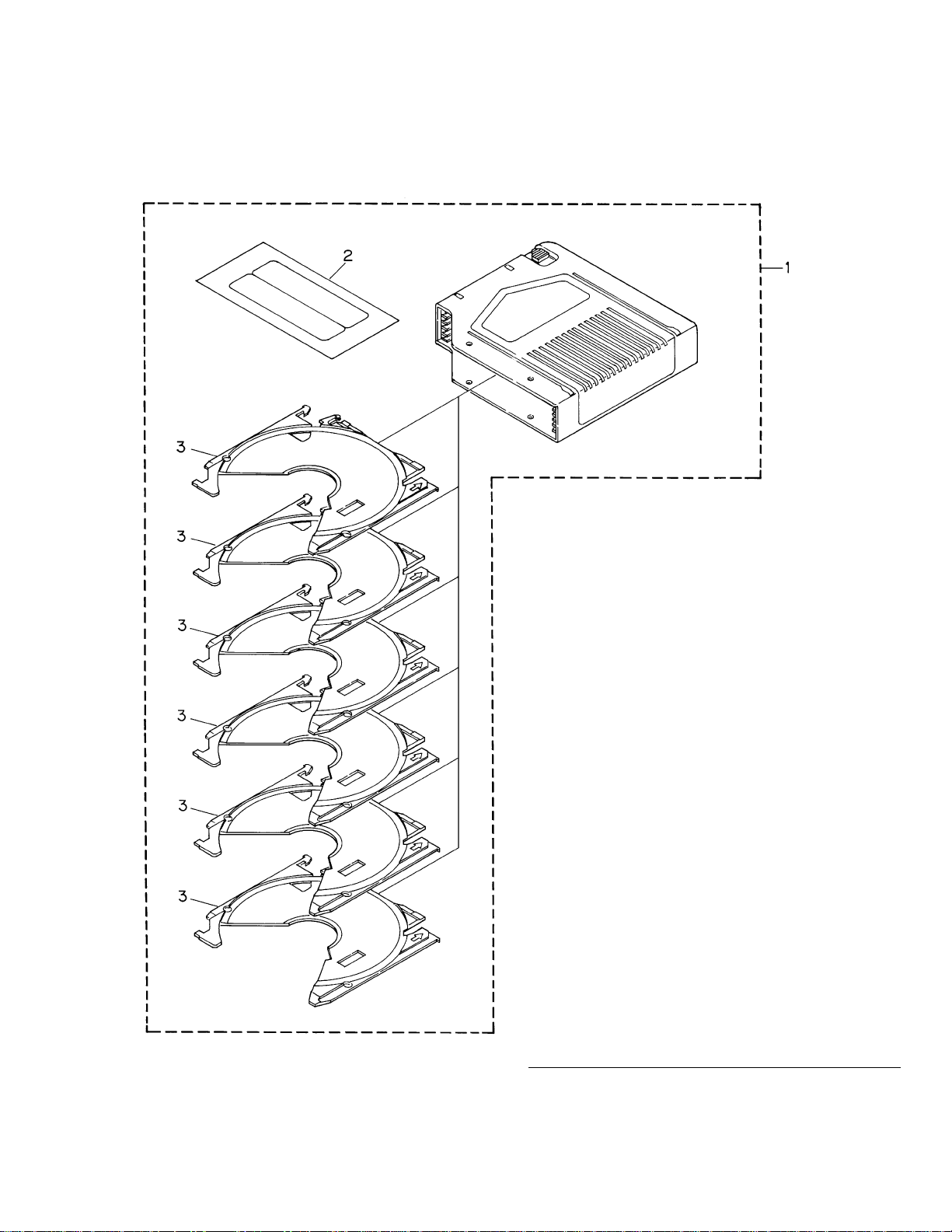
2.4 MAGAZINE ASSY
1 Magazine Assy CXB4027
2 Label CRW1395
3 Tray CNV5341
- MAGAZINE ASSY SECTION PARTS LIST
Mark No. Description Part No.
12
CDX-P656,P25
1
23
4
1234
D
C
B
A
A
C
D
E
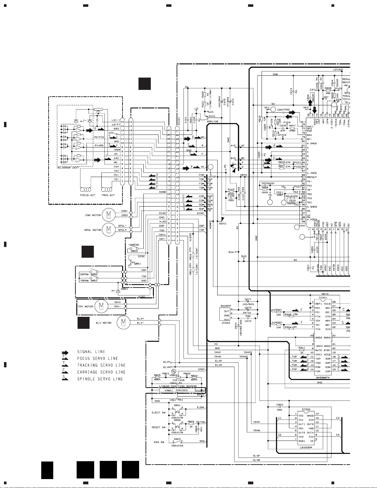
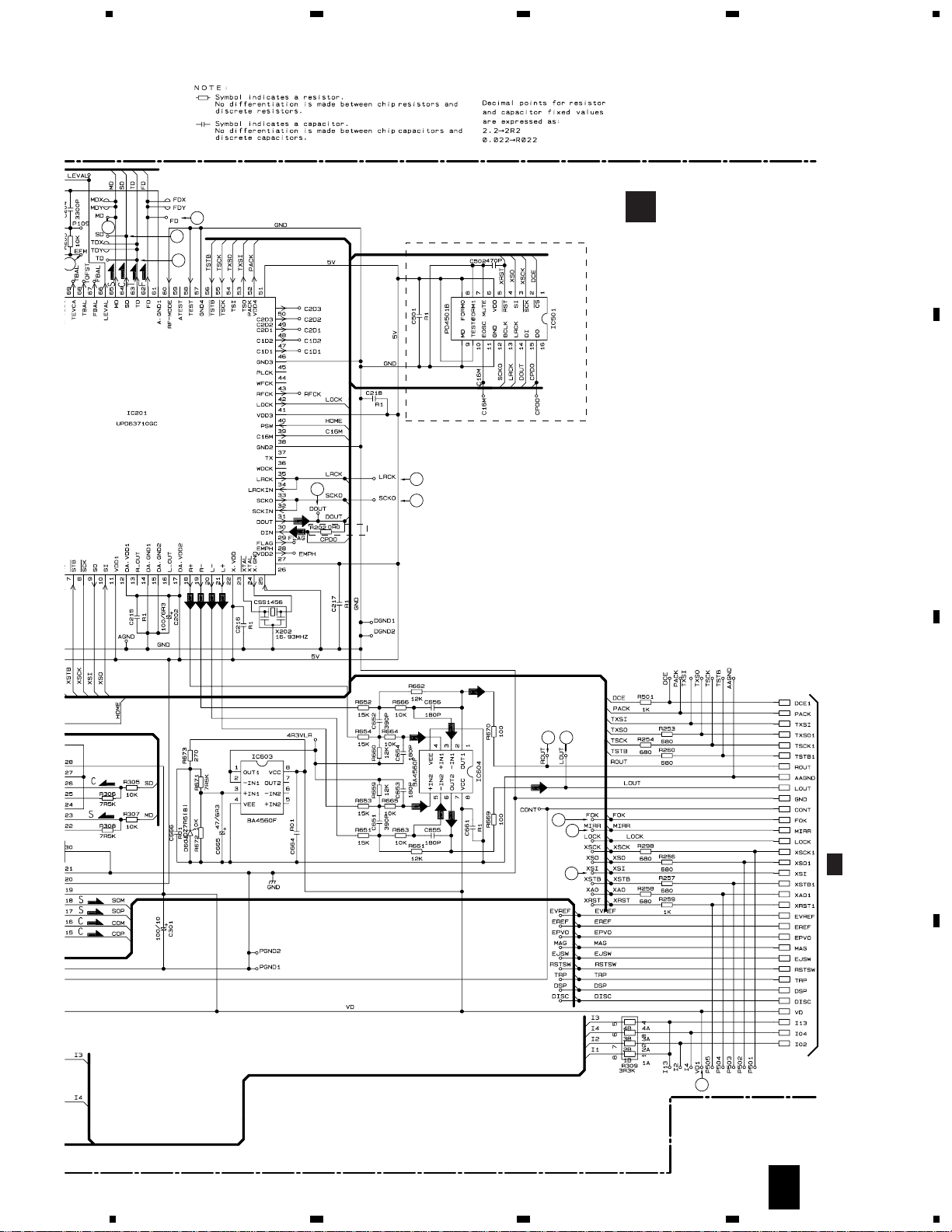
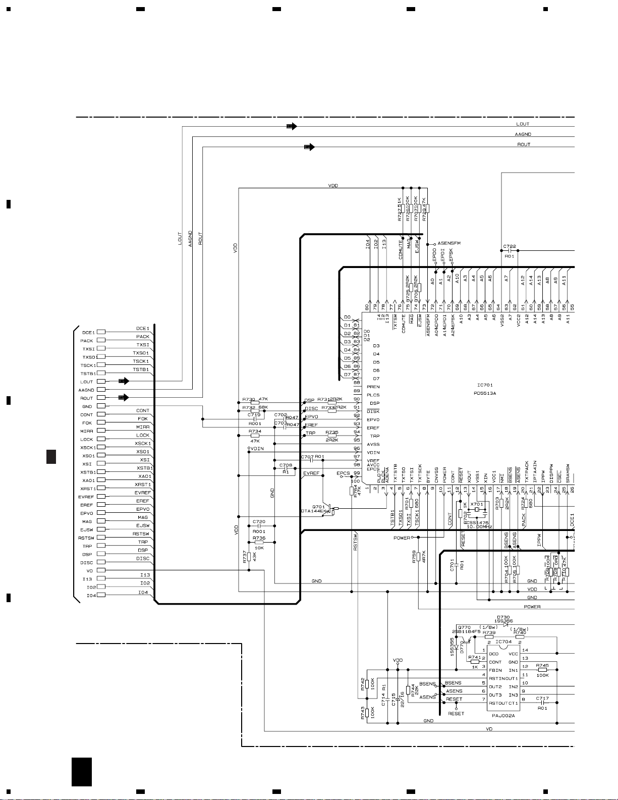
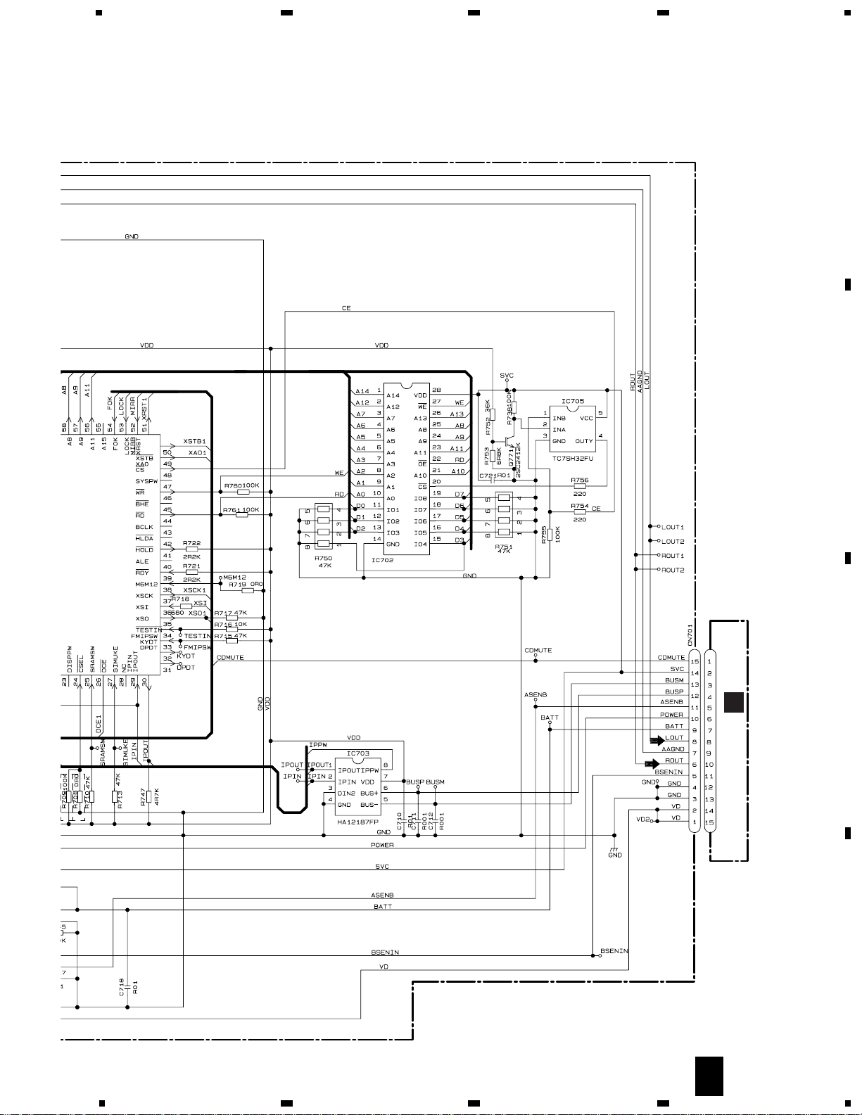
3. SCHEMATIC DIAGRAM
3.1 OVERALL CONNECTION DIAGRAM
Note: When ordering service parts, be sure to refer to “EXPLODED VIEWS AND PARTS LIST” or “ELECTRICAL
PARTS LIST”.
M853
CXB3005
M852
CXB3006
M851
CXB3003
M854
CXB3004
PICKUP UNIT(SERVICE)
CXX1285
CSN1051
CSN1051
CSN1052
CN504-2
PT4800
10k
1k(B)
C
MECHANISM
PCB
D
SWITCH PCB
E
MOTOR PCB
MOT
4CH SERVO DRIV
RF-A
DSP
1
12
6
8
13
21
10
4
CN801
CN802
1/2
13
CDX-P656,P25
5
6
78
5
6
78
D
C
B
A
A
CD CORE UNIT
A
2/2
MOTOR DRIVER
DRIVER
RF-AMP,SERVO,
DSP,DAC
18
7
2
5
19 20
15
17
16
12
3
9
11
10
UCmodel
EW model
A
1/2
14
CDX-P656,P25
1
23
4
1234
D
C
B
A
A
1/2
SYSTEM CONTROLLER
UCmodel
EWodel
A
2/2
15
CDX-P656,P25
5
6
78
5
6
78
D
C
B
A
GGC1257
(SRM2B256SLTMX70)
B
CN911
SRAM
IP-BUS DRIVER
POWER UNIT
UCmodel
EWodel
A
2/2
 Loading...