

Page 1

Operation Manual
CDX-FM673
Mode d’emploi
UNIVERSAL
MULTI-CD SYSTEM
SYSTEME DE CD
MULTIPLE UNIVERSEL
130FM673
Page 2

Dear Customer ............................................ 4
Precautions ................................................. 5
Using the Compact Discs Magazine ......... 6~8
Inserting discs ................................................... 6~7
Loading the magazine
............................................ 8
Playing Compact Discs .......................... 9~15
Start the CD player
................................................ 9
Disc Number Search
.............................................. 9
Using Track Search/Fast Forward and Reverse
........ 10
Pausing
..............................................................
11
Repeat
............................................................... 11
Random Play
....................................................... 12
Setting Player to Play Discs via Radio
................ 13~14
Display shows this message
.................................
15
Pressing the Clear Button .......................... 16
Discs ........................................................ 16
Transportation of multi-CD player .............. 17
Specifications ........................................... 18
Contents
2
English
Page 3

Table des matières
3
Cher Client ................................................ 19
Précautions ............................................... 20
Utilisation du chargeur de disque compact
..... 21~23
Mise en place des disques ................................ 21~22
Mise en place d’un chargeur
.................................. 23
Lecture de disques compacts ............... 24~30
Commandez la lecture du CD ................................ 24
Recherche de numéro de disque ............................ 24
Utilisation de la recherche de plage/
de l’avance rapide et de l’inversion
........................ 25
Pause ................................................................. 26
Répétition
........................................................... 26
Lecture aléatoire
.................................................. 27
Réglage du lecteur pour la lecture de
disques via la radio
.......................................... 28~29
Affichage du message ........................................... 30
En appuyant sur la touche d’effacement ..... 31
Disques ..................................................... 31
Transport du lecteur de CD à chargeur ....... 32
Spécifications ............................................ 33
Français
Page 4
Dear Customer
4
Selecting fine audio equipment such as the unit you’ve just
purchased is only the start of your musical enjoyment. Now it’s time
to consider how you can maximize the fun and excitement your
equipment offers. This manufacturer and the Electronic Industries
Association’s Consumer Electronics Group want you to get the most
out of your equipment by playing it at a safe level. One that lets the
sound come through loud and clear without annoying blaring or
distortion—and, most importantly, without affecting your sensitive
hearing.
Sound can be deceiving. Over time your hearing “comfort level”
adapts to higher volumes of sound. So what sounds “normal” can
actually be loud and harmful to your hearing. Guard against this by
setting your equipment at a safe level BEFORE your hearing adapts.
To establish a safe level:
• Start your volume control at a low setting.
• Slowly increase the sound until you can hear it comfortably and
clearly, and without distortion.
Once you have established a comfortable sound level:
• Set the dial and leave it there.
Taking a minute to do this now will help to prevent hearing damage or
loss in the future. After all, we want you listening for a lifetime.
We Want You Listening For A Lifetime
Used wisely, your new sound equipment will provide a lifetime of
fun and enjoyment. Since hearing damage from loud noise is often
undetectable until it is too late, this manufacturer and the Electronic
Industries Association’s Consumer Electronics Group recommend
you avoid prolonged exposure to excessive noise. This list of sound
levels is included for your protection.
Decibel
Level Example
30 Quiet library, soft whispers
40 Living room, refrigerator, bedroom away from traffic
50 Light traffic, normal conversation, quiet office
60 Air conditioner at 20 feet, sewing machine
70 Vacuum cleaner, hair dryer, noisy restaurant
80 Average city traffic, garbage disposals, alarm clock at two feet.
THE FOLLOWING NOISES CAN BE DANGEROUS
UNDER CONSTANT EXPOSURE
90 Subway, motorcycle, truck traffic, lawn mower
100 Garbage truck, chain saw, pneumatic drill
120 Rock band concert in front of speakers, thunderclap
140 Gunshot blast, jet plane
180 Rocket launching pad
Information courtesy of the Deafness Research Foundation.
Page 5
Precautions English
5
• When you use this universal multi-CD
system, the effective sensitivity of your
radio will be reduced slightly.
• When you turn the car radio off, the
system stays on. If you leave it on for a
long time, the car battery may go flat.
• When driving on an uneven road, the
player may not reproduce every sound
properly.
• When this universal multi-CD system is
connected to a vehicle’s diversity antenna, there may be distortion if a station is
broadcasting a strong signal on the frequency you’re using for the system. If
this occurs, switch to another frequency.
• During winter the inside of the vehicle
may be very cold. If the heater is turned
on and the player is used soon after, the
disc or optical parts (prism, lens, etc.)
may become misted up, and the player
will not operate correctly. If the disc is
misted up, wipe it with a soft cloth. If
the optical parts are misted up, wait for
about an hour for them to warm up.
They will return to their normal condition.
• This product conforms to the track skip
function of the CD-R disc. The tracks
containing the track skip information are
skipped over automatically.
Important
The serial number of this device is located
on the rear of the unit. For your own security and convenience, be sure to record
this number on the enclosed warranty
card.
After-sales service for Pioneer
products
Please contact the dealer or distributor
from where you purchased the product
for its after-sales service (including
warranty conditions) or any other information. In case the necessary information is not available, please contact the
companies listed below:
Please do not ship your product to the
companies at the addresses listed
below for repair without advance contact.
U.S.A.
Pioneer Electronics Service, Inc.
CUSTOMER SERVICE DEPARTMENT
P.O. Box 1760
Long Beach, CA 90801
800-421-1404
CANADA
Pioneer Electronics of Canada, Inc.
CUSTOMER SERVICE DEPARTMENT
300 Allstate Parkway
Markham, Ontario L3R OP2
(905) 479-4411
1-877-283-5901
For warranty information please see
the Limited Warranty sheet included
with your product.
NOTES:
THIS DEVICE COMPLIES WITH PART 15
OF THE FCC RULES. OPERATION IS
SUBJECT TO THE FOLLOWING CONDITIONS: (1)THIS DEVICE MAY NOT
CAUSE HARMFUL INTERFERENCE,
AND (2)THIS DEVICE MUST ACCEPT
ANY INTERFERENCE RECEIVED,
INCLUDING INTERFACE THAT MAY
CAUSE UNDESIRED OPERATION.
CHANGES OR MODIFICATIONS TO
THIS PRODUCT BY OTHER THAN AN
AUTHORIZED SERVICE FACILITY
COULD VOID AUTHORIZATION TO USE
THIS EQUIPMENT.
SHOULD THE USE OF THIS PRODUCT
CAUSE HARMFUL INTERFERENCE
WITH ANY RADIO DEVICES, CONTACT
YOUR DEALER.
THE USE OF THIS PRODUCT MAY
CAUSE A NOTICEABLE LOSS IN AM
SIGNAL RECEPTION. THIS IS NOT A
MALFUNCTION BUT IS PART OF THE
NORMAL OPERATION OF THIS
MODEL.
CAUTION:
USE OF CONTROL OR ADJUSTMENT
OR PERFORMANCE OF PROCEDURES
OTHER THAN THOSE SPECIFIED
HEREIN MAY RESULT IN HAZARDOUS
RADIATION EXPOSURE.
CAUTION:
THE USE OF OPTICAL INSTRUMENTS
WITH THIS PRODUCT WILL INCREASE
EYE HAZARD.
Page 6
Using the Compact Discs Magazine
6
1
2
3
4
5
6
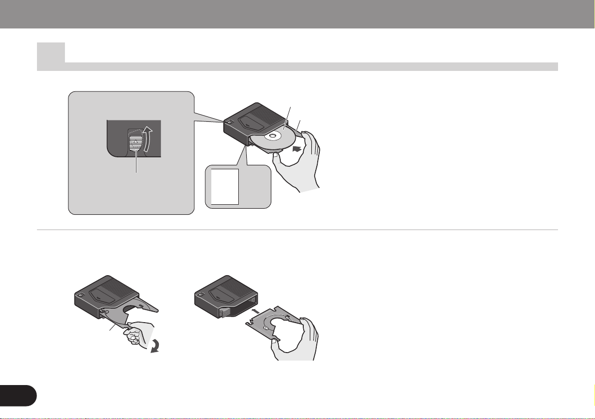
Hold down the magazine
lock button and, pull the
tray out.
Slide out the disc tray
Disc tray
Position the disc with
the label upward.
Inserting discs [Page 6~7]
Disc 1
to
Disc 6
Changing disc trays
Align the disc tray with the left and right
grooves, and push it in until you hear it
click.
Gently pull the disc tray out.
Disc tray
Page 7
English
7
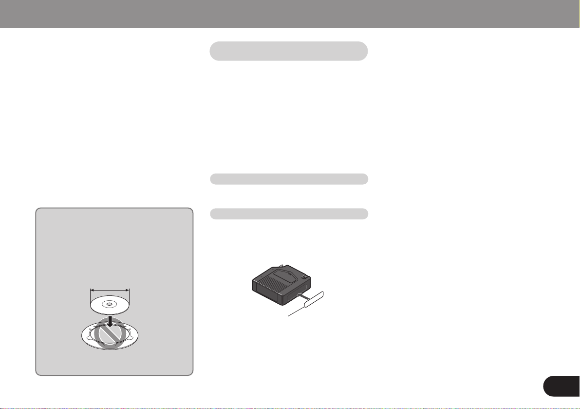
Notes on 8-cm (3-inch) CDs
Do not use an 8-cm CD adapter. If it is
used, the player may fail. To load an
8-cm CD, you need a special 8-cm CD
tray (Part No. CXB5931). Ask your
Pioneer service station about it.
• Do not put the magazine in a place
where it will be exposed to high
temperatures or direct sunlight.
• Do not disassemble the magazine.
• Take care not to drop the magazine or
knock it against anything.
• Do not use cracked or warped trays.
• Never insert anything other than discs.
Do not attach a label or tape to a disc.
• The use of benzine, thinner, insecticide,
or other volatile chemicals may damage
the magazine surface.
If you need more magazines, please ask
your nearest dealer for magazine JD-612V.
Attach the supplied label in the specified position. Attaching the label in an
incorrect place or attaching more than
one label will cause malfunction.
Label
• Be sure to remove the disc before
changing a disc tray.
• If the tray is not aligned with the right
and left grooves, it cannot be pushed to
the end. Do not bend or force the tray.
• Always load 6 trays in a magazine to
prevent loss or warping of trays.
• If you load a disc with the label general-
ly printed in black facing down, not only
will the player not be able to recognize
whether the disc is set or not, but also,
the display unit will not display an error
message to let you know about it. So
make sure all the discs in each magazine have their label sides facing up.
Precautions when handling
magazines
Extra magazines
Attaching the label
8cm
Page 8
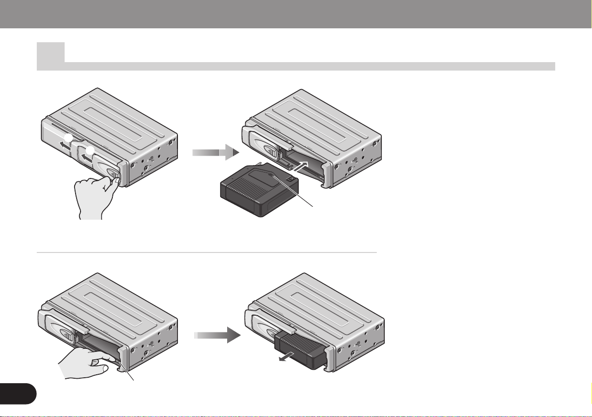
Press the eject
button.
Using the Compact Discs Magazine
8
2
1
Insert the magazine.
• Do not put your fingers in the magazine
tray as this may lead to incorrect operation and damage to the player.
• If the label on the magazine is coming
off or wrinkled up, it may damage the
eject mechanism, and in some cases,
the magazine may not be ejected.
Therefore, remove a damaged label
completely before use.
• Never leave the door open while playing discs. The entry of dirt, dust, or any
other foreign matter into the player may
cause it to fail.
Loading the magazine
To remove the magazine
Insert the magazine with
the arrow upward.
1 Slide and open the door.
2 Open it fully until it locks with a click.
Page 9
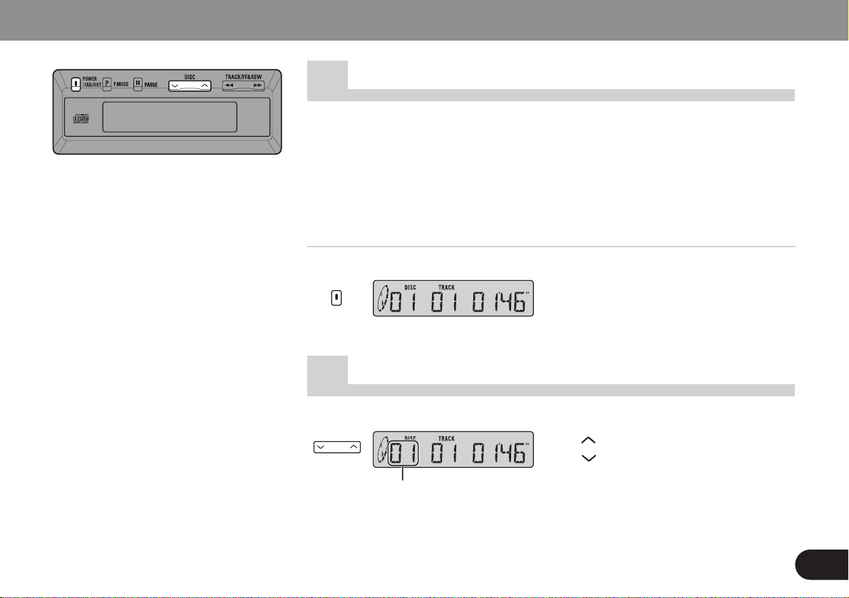
: increase the number.
: decrease the number.
Playing Compact Discs English
9
1.Switch the radio on and tune to
Modulating Frequencies.
• The initial value is 89.1 MHz.
(
See Page 13 regarding switching CD
player transmission frequency.)
• If your radio does not have muting, there
may be some noise before power switch
of control unit is ON. If this happens, turn
down the volume of the radio.
2.Press button to switch on and
start the player.
Start the CD player
Disc Number Search
Disc Number
Page 10

10
Using Track Search/Fast Forward and Reverse
Playing Compact Discs
This product lets you select the
track search function or fast forward/reverse function by changing
the length of the time you press
the button.
Track Number
Elapsed play time
Track search 0.5 seconds or less
Fast-forward/Reverse Continue pressing
: decrease the number.
: Fast Reverse
: increase the number.
: Fast Forward
Page 11

11
English
Press button to pause during disc
playback.
Press button again to release pause.
Pausing
Repeat
MEMO
You can select a track using the track
search during pause. (“PAUSE” is off
while a track is being searched.) When
the track search ends, the found track
is paused at its beginning.
Track Repeat
Play the current track repeatedly.
Disc Repeat
Play the same disc repeatedly.
Normal play
Play all disc loaded in the magazine in the CD player repeatedly.
Each press of button, the mode
changes.
MEMO
• Changing to a different song or using
fast forward or reverse during track
repeat will cause the mode to change
to disc repeat.
• Changing discs during track repeat or
disc repeat will cause the mode to
change to normal play.
Page 12

1.Select the desired repeat mode.
2.Hold down button for more than 2
second.
Once the current track has been played,
the microprocessor will randomly select
the next and subsequent tracks.
To cancel random play, hold down button for more than 2 seconds again.
Random Play
Playing Compact Discs
MEMO
If track repeat is selected as the repeat
mode in step 1, it will automatically
switch to disc repeat mode and random play will begin.
Displayed during random play.
12
Random play will be performed
within the selected repeat mode.
Example : Disc Repeat (See Page 11.)
Page 13

English
13
1.Hold down button for more than 2
seconds. The modulator setting
mode will be entered, and the frequency will be displayed.
MEMO
If you do nothing within the next 8 seconds, the modulator setting mode
returns to the normal mode without
changing the most recent settings.
Modulating frequencies selector
This system can change the frequency at
which the FM car radio receives the CD
audio signals within the range of 87.9 to
90.1 MHz in 0.2-MHz increments. (The initial setting is 89.1 MHz.) If there is a
strong broadcast station signal near the
current frequency, radio interference may
occur. If it occurs, change the frequency.
Source level adjuster
When you play discs, If the volume is low
compared with that for FM increase the
volume level. If the volume is high and
there is distortion, decrease the volume
level. (The initial setting is “LEVEL-4”.)
Setting Player to Play Discs via Radio [Page 13~14]
Page 14

Playing Compact Discs
Item
Level
2.Set the items while referring to the chart on the
left.
Button Display
The last adjustment is kept as final.
3.Press the button for 2 seconds or
more to return to normal play.
Frequency
14
Page 15

English
15
Take action according
to the chart below.
Check discs and magazine
once more.
If it still doesn’t work
after checking.
Press the CD player’s Clear
button. (See Page 16.)
If it still doesn’t work.
Read “After-sales service
for Pioneer products” and
request servicing.
Message
No MAGAZINE (appears)
No MAGAZINE (flashes for 5 seconds)
READY
Err 11, Err 12, Err 14, Err 17
Err 30
Err 11, Err 14
Err 14
Err 44
NO DISC
Err 10, Err 11, Err 12, Err 14, Err 17
Err 19, Err 30, Err 50, Err 60, Err 70
Err A0, Err A1
Cause
Removing the magazine from the CD player
during CD play.
Power was turned on while the magazine
was not loaded in the CD player.
The CD player is warming up.
Dirt or a scratch on the disc stops the laser
beam from being able to focus.
Dirt or a scratch on the disc hinders the track
number search function.
The disc has been inserted upside down.
An unrecorded compact disc (CD-R), which
can be recorded on once is being used.
All tracks are setting track skip.
There is no disc in the magazine.
Electrical or mechanical system fault.
Treatment
To use this system, load the magazine into
the CD player and then turn on the power.
Turn on the power after loading the magazine into the CD player.
Please wait a few moments.
Wipe off the dirt. Exchange the disc if it has
been scratched. (See Page 16.)
Confirm that the disc has been inserted right
side down. (See Page 6.)
When you use a CD-R, load one that has
been recorded on.
Replace the disc.
Load a disc into the magazine. (See Page 6.)
Turn the car ignition switch off and on
again, or press power ON/OFF button on the
display unit, and start the CD playing again.
Display shows this message
Page 16

Pressing the Clear Button
After connecting everything up, press the
clear button with the tip of a pencil. If the
power will not switch on, or if the CD
player does not operate, when the button
on the control unit is pressed, or if the
control unit display is incorrect, press this
button with the tip of a pencil to restore
normal operation. (This button is located
inside the door.)
Discs
Clear button
Magazine Disc
• With this unit, use discs and magazines
bearing the above marks.
• This product is designed for use with
conventional,fully circular CDs only. Use
of shaped CDs are not recommended
for this product.
• Check all CDs before playing, and discard cracked, scratched or warped discs.
• Normal playback of CD-R discs other
than those recorded with a music CD
recorder may not be possible.
• Playback of music CD-R discs, even
those recorded with a music CD
recorder, may not be possible with this
product due to disc characteristics or
scratches or dirt on the disc. Dirt or condensation on the lens inside this product
may also prevent playback.
• Read the precautions with the CD-R
discs before using.
• Avoid touching the recorded (iridescent)
surface when handling discs.
• Do not affix labels or apply chemicals to
discs.
• Wipe dirty or damp discs outward from
the center with a soft cloth.
• Keep discs out of direct sunlight and
high temperatures.
16
COMPACT
DIGITAL AUDIO
Page 17

Transportation of multi-CD player English
17
A transport screw has been attached to
the set in order to protect it during transportation. After removing the transport
screw, cover the hole with the supplied
seal.
Be sure to remove the transport screw
before mounting the set. The removed
transport screw should be retained in the
accessory bag for use the next time the
set is transported.
Seal
After removing the transport screw,
cover the hole with the supplied seal.
Transport screw
Attach to the original position before
transporting the set.
Page 18

Specifications
18
CD Player unit
System .......... Compact disc audio system
Usable discs ......................... Compact Disc
Signal format
................. Sampling frequency: 44.1 kHz
Number of quantization bits: 16; linear
Power source
....... 14.4 V DC (10.8 — 15.1 V allowable)
Max. current consumption ................ 1.0 A
Weight .................................. 1.9 kg (4.2 lbs)
Dimensions
................. 248 (W) × 66 (H) × 168 (D) mm
[9-3/4 (W) × 2-5/8 (H) × 6-5/8 (D) in]
FM modulator usable frequency
............. 87.9/88.1/88.3/88.5/88.7/88.9/89.1
/89.3/89.5/89.7/89.9/90.1 MHz
Antenna Switching unit
Weight ................................... 140 g (0.3 lbs)
Dimensions
..................... 45 (W) × 25 (H) × 43 (D) mm
[1-3/4 (W) × 1 (H) × 1-5/8 (D) in]
Display unit
Weight ..................................... 78 g (0.2 lbs)
Dimensions
....................100 (W) × 37 (H) × 18 (D) mm
[3-15/16 (W) × 1-7/16 (H) × 5/8 (D) in]
Note:
Specifications and the design are subject
to possible modification without prior
notice due to improvements.
Page 19

Printed in Thailand
Imprimé en Thaïlande
<CRD3321-A/N> UC
<KFJFF/00H00000>
Published by Pioneer Corporation.
Copyright © 2000 by Pioneer Corporation.
All rights reserved.
Publication de Pioneer Corporation.
Copyright © 2000 Pioneer Corporation.
Tous droits de reproduction et de traduction réservés.
PIONEER CORPORATION
4-1, MEGURO 1-CHOME, MEGURO-KU, TOKYO 153-8654, JAPAN
PIONEER ELECTRONICS (USA) INC.
P.O. Box 1760, Long Beach, California 90801, U.S.A.
TEL: (800) 421-1404
PIONEER EUROPE NV
Haven 1087, Keetberglaan 1, B-9120 Melsele, Belgium
TEL: (0) 3/570.05.11
PIONEER ELECTRONICS AUSTRALIA PTY. LTD.
178-184 Boundary Road, Braeside, Victoria 3195, Australia
TEL: (03) 9586-6300
PIONEER ELECTRONICS OF CANADA, INC.
300 Allstate Parkway, Markham, Ontario L3R OP2, Canada
TEL: (905) 479-4411
PIONEER ELECTRONICS DE MEXICO, S.A. de C.V.
San Lorenzo 1009 3er. Piso Desp. 302
Col. Del Valle Mexico, D.F. C.P. 03100
TEL: 5-688-52-90
Page 20

Connecting the Units/Connexion des appareils
D
A
C
B
E
F
Yellow
To the terminal always supplied with power
regardless of ignition switch position.
Jaune
Vers une borne alimentée en permanence,
indépendamment de la position de la clé de
contact.
Red
To electric terminal controlled by ignition switch (12 V DC) ON/OFF.
Rouge
Vers une borne commandée par la clé
de contact (12 V CC).
Black (ground)
To the vehicle (metal) body.
Noir (masse)
Vers la carrosserie (masse) du véhicule.
Fuse holder
Porte-fusible
Display unit
Unité d’affichage
CD Player unit
Unité de lecteur CD
Car antenna plug
Fiche d’antenne de Voiture
To FM car radio
Vers Auto radio FM
Antenna switching unit
Unité de commutateur d’antenne
Resistor
Resistore
• Before mounting, connect the units temporarily. Check that the units and the system are working correctly.
• After connection is complete, press the
clear button on the CD player with the tip
of a pencil.
• Be sure to connect the ground lead
(black) to the vehicle body or some other
metal part that is properly grounded to
the chassis. If the ground lead is not properly connected, noise may occur or the
system may not operate correctly.
• This unit is for vehicles with a 12-volt battery and negative grounding. Before
installing it in a recreational vehicle, truck,
or bus, check the battery voltage.
• To avoid shorts in the electrical system,
be sure to disconnect the battery (–) cable
before beginning installation.
• Check whether installation and wiring
have been completed correctly. Replace
the removed car components, then
connect the end of the cable to the negative (–) terminal of the battery.
• Secure the wiring with cable clamps or
adhesive tape. To protect the wiring,
wrap adhesive tape around them where
they lie against metal parts.
• Route and secure all wiring so it cannot
touch any moving parts, such as the gear
shift, handbrake, and seat rails. Do not
route wiring in places that get hot, such
as near the heater outlet. If the insulation
of the wiring melts or gets torn, there is a
danger of the wiring short-circuiting to
the vehicle body.
• Do not pass the yellow lead through a
hole into the engine compartment to connect to the battery. This will damage the
lead insulation and cause a very dangerous short.
• Do not shorten any leads. If you do, the
protection circuit may fail to work when it
should.
• Never feed power to other equipment by
cutting the insulation of the power supply
lead of the unit and tapping into the lead.
The current capacity of the lead will be
exceeded, causing over heating.
• Replace fuses only with the types stipulated on the fuse holder.
• Avant l’installation, retirer la goupille de
transport et raccorder provisoirement les
appareils. Vérifier que les appareils et la
chaîne fonctionnent correctement.
• Lorsque le raccordement est effectué,
appuyer sur le bouton d’annulation du
lecteur CD avec la pointe d’un crayon.
• Veiller à bien raccorder le conducteur de
masse (noir) à la carrosserie du véhicule
ou à toute autre pièce métallique correctement mise à la masse sur le châssis.
Si le conducteur de masse n’est pas raccordé correctement, il ourrait en résulter
des parasites, ou la chaîne pourrait ne
pas fonctionner correctement.
• Cet appareil est destiné aux véhicules
avec une batterie de 12 V, négative à
masse négative. Avant de l’installer dans
un véhicule de loisir, un camion ou un
car, vérifier la tension de la batterie.
• Afin d’éviter des court-circuits dans le
système électrique, s’assurer de déconnecter le câble (–) de batterie avant de
commencer l’installation.
• Vérifier si l’installation et le câblage ont
été complétés correctement. Remplacer
les composantes de voiture retirées, puis
connecter l’extrémité du câble à la borne
négative (–) de la batterie.
• Fixer le câblage au moyen des attaches
de câble ou une bande adhésive. Pour
protéger le câblage, enrouler la bande
adhésive autour des câbles à l’endroit où
ceux-ci sont placés contre les parties
métalliques.
• Acheminer et fixer tout le câblage de telle
sorte qu’il ne touche pas les pièces
mobiles, comme le levier de changement
de vitesse, le frein à main et les rails des
sièges. Ne pas acheminer les câbles dans
des endroits qui peuvent devenir chauds,
comme près de la sortie de radiateur.
Si l’isolation des câbles fond ou se
déchire, il existe un danger de court-circuit des câbles avec la carrosserie du
véhicule.
• Ne faites pas passer le conducteur jaune
dans le compartiment moteur par un trou
pour le connecter avec la batterie. Ceci
endommagerait l’isolation du conducteur
et causerait un dangereux court-circuit.
• Ne pas court-circuiter les conducteurs.
Sinon, le circuit de protection risque de
ne pas fonctionner.
• Ne jamais alimenter un autre appareil en
coupant l’isolation du conducteur d’alimentation de l’appareil et en la branchant
dans le conducteur. L’intensité de courant
du conducteur sera dépassée provoquant
ainsi une surchauffe.
• Remplacer les fusibles seulement par des
fusibles de type spécifié sur le portefusible.
English Français
A B
D
C
FE
Parts for connection/
Pièces requises pour les raccordements
Pass leads and
cords through.
Engagez cordons
et câbles dans
l’ouverture.
Pass leads and cords through D and
fix in place.
Engagez cordons et câbles dans
l’ouverture D et assurez leur fixation.
<KFJFF/00H00000> <CRD3322-A/N> UC
INSTALLATION MANUAL
MANUEL D’INSTALLATION
CDX-FM673
Published by Pioneer Corporation.
Copyright © 2000 by Pioneer Corporation.
All rights reserved.
Publication de Pioneer Corporation.
Copyright © 2000 Pioneer Corporation.
Tous droits de reproduction et de traduction réservés.
Printed in Thailand
Imprimé en Thaïlande
This product conforms to CEMA cord colors.
Le code de couleur des câbles utilisé pour ce produit est conforme à CEMA.
Cords for this product and those for other products
may be different colors even if they have the same
function. When connecting this product to another
product, refer to the supplied Installation manuals
of both products and connect cords that have the
same function.
Les câbles de cet appareil et ceux d’autres appareils
peuvent fort bien ne pas être de la même couleur
bien que remplissant la même fonction. Pour relier
cet appareil à un autre appareil, utilisez le manuel
d’installation de chacun et effectuez les raccordements en ne tenant compte que de la fonction de
chaque câble.
550 cm
100 cm
540 cm
30 cm
50 cm
Choke coil
Bobine d’arrêt
Page 21

Removing the Display Unit/
Enlever de I’afficheur
Insert the G that comes with the unit as
shown in the illustration. Turn it to the left
and then pull it towards you.
Insérer la pièce G fournie avec l’appareil
comme montré sur l’illustration. La tourner
vers la gauche puis la tirer vers soi.
English Français
3
2
1
E
D
A
F
Tout d’abord, percer les trous d’installation
dans la console, etc.
• Avant de percer les trous dans la console,
s’assurer que l’on peut le faire sans danger et veiller à ne pas endommager les
câbles d’alimentation électrique.
• La profondeur minimale requise pour le
support de montage affleurant est de
20 mm.
Installing the Display Unit/Installation de l’afficheur
A
×1
BC
D
EF
G
×1 ×1 ×1
×1 ×1×2
Parts for display unit mounting/
Pièces requises pour le montage de l’afficheur
Fasten the display unit with Velcro tape/
Fixer I’afficheur à I’aide d’une bande Velcro
Installation using the flush mounting bracket/
Installation au moyen du support du montage affleurant
• Thoroughly wipe off the surface before
affixing the Velcro tape.
• Obviously, it is very dangerous if the cord
gets tangled in the steering wheel, so
install the cord so that it cannot get in the
way.
• Essuyez soigneusement la surface avant
d’attacher le morceau de bande Velcro.
• Il est naturellment dangereux si le cordon
sera enchevêtré au volant de direction, et
il faudra donc installer le cordon de telle
façon qu’il ne soit pas pris.
English Français
English Français
Start by opening installation holes in the
console, etc.
• When opening holes in the console, etc.,
confirm that there is no object at the rear
of the console, and be careful not to cut
off the power supply cord.
• A minimum depth of 20 mm is required
for installation of the flush mounting
bracket.
Fit the D into the opening in the console,
etc., raise the claws of the D with a flatbladed screwdriver, and secure the bracket
in place.
Fit the E into the D (the top and bottom of
the holder are predetermined), then secure
it with F.
Pass the display unit (A) cord through the
hole in the holder, and fit the display unit
into the holder.
Engager la pièce D dans l’ouverture de la
console, etc., soulever les griffes de la pièce
D au moyen d’un tournevis plat et assurer
de cette manière le maintien du support.
Engager la pièce E dans la pièce D (les
parties supérieure et inférieure du support
sont repérées) et assurer le maintien au
moyen de F.
Faire cheminer le cordon de l’afficheur (A)
à travers le trou du support puis engager
l’afficheur dans le support.
1
2
3
4
Velcro tape
Bande Velcro
Claws
Raise the claws.
Mâchoires
Soulevez les mâchoires.
Console, etc.
Console, etc.
110 – 111 mm
40 – 41 mm
Velcro tape
Bande Velcro
(Rough surface)
(Surface rugueuse)
(Soft surface)
(Surface douce)
Page 22

A transport screw has been attached to the
set in order to protect it during transportation. After removing the transport screw,
cover the hole with the supplied seal. Be
sure to remove the transport screw before
mounting the set. The removed transport
screw should be retained in the accessory
bag for use the next time the set is transported.
Des vis sont fixées sur le lecteur de façon à
le protéger pendant le transport. Après
avoir retiré la vis de transport, bouchez le
trou au moyen du cache fourni. Veillez à
retirer ces vis avant d’installer le lecteur.
Conservez les vis dans le sac contenant les
accessoires de manière à ne pas les égarer
et à être en mesure de les remettre en place
en cas de transport.
1
Horizontally/Horizontalement Vertically/Verticalement
Transportation of multi-CD Player/
Transport du lecteur de CD à chargeur
English Français
Installing the CD Player Unit/Installation de la Unité lecteur CD
A
B
A
B
B
A
A
B
Mounting board
Platine
Mounting board
Platine
Mounting the player on the mounting board with self-tapping screws/
Fixation du lecteur sur une platine à I’aide de vis autotaraudeuses
Suspending the player from the parcel shelf with hex-screws/
Fixation du lecteur sous la plage arrière au moyen de vis à tête hexagonale
1
Parcel shelf
Plage arrière
A
A
B
B
Transport screw
Attach to the original position before transporting the set.
Vis de transport
Replacez ces vis dans leur position d’origine avant de transporter I’appareil.
Seal
After removing the transport screw, cover the hole with
the supplied seal.
Cache
Après avoir retiré la vis de transport, bouchez le trou au
moyen du cache fourni.
Put marks.
Marquez ces emplacements.
Put marks.
Marquez ces emplacements.
Put marks.
Marquez ces emplacements.
A
BC
D
×2 ×4 ×4 ×4 ×4
E
Mounting parts/Pièces de fixation
Refer to the following illustrations of mounting parts when mounting the player.
Les pièces servant à la fixation du lecteur sont illustrées
ci-dessous.
A
A
Use the holes indicated with arrows.
Percez les trous indiqués par les flèches.
Use the holes indicated with arrows.
Percez les trous indiqués par les flèches.
A
Use the holes indicated with arrows.
Percez les trous indiqués par les flèches.
Page 23

2
3
E
E
D
D
φ
6.5 ~ 7 mm
Mounting angle/
Angle de montage
Use any angle in
this range (up to
90 degrees).
Tout angle compris entre 0 et 90
degrés convient.
The player cannot be installed
in this direction.
Le lecteur ne
peut pas être
installé de cette
manière.
Angle switching
dial
Sélecteur d’angle
de montage
5 steps
5 positions
Angle switching dial adjustment
Set the dial so that its slot is closest to the horizontal direction with respect to the
ground surface.
Positionnement du sélecteur d’angle de montage
Positionnez le sélecteur de manière que la fente soit horizontale.
The angle switching dial must be set on both sides of
the player to the same position.
Les boutons de commutation d’angle placés de chaque
côté du lecteur doivent occuper les mêmes positions.
Top
Sommet
2 3
English Français
C
C
• Consult with your nearest dealer if installation requires the drilling of holes or other
modifications of the vehicle.
• Before finally installing the unit, connect the
wiring temporarily and make sure it is all
connected up properly and the unit and the
system work properly.
• Use only the parts included with the unit to
ensure proper installation. The use of unauthorized parts can cause malfunctions.
• When mounting the player, make sure none
of the leads are trapped between the player
and the surrounding metalwork or fittings.
Location
• Install the unit where it does not get in
the driver’s way and cannot injure the
passenger if there is a sudden stop, like
an emergency stop.
• Be sure to mount the player on a rigid
surface which is firm enough to hold the
player in the proper position under all circumstances. Failure to do so may affect
the optimum performance of the player.
• Before drilling a hole into the trunk, confirm that there is nothing behind the hole.
Never drill a hole in the fuel tank or any
other important part.
• Do not mount the player near the heater
outlet, where it would be affected by heat,
or near the doors, where rainwater might
splash onto it.
• Do not mount the player on the spare tire
board or any other unstable place.
• Mount the player in a place where it does
not prevent the spare tire, jack, or tools
from being easily removed.
• Do not mount the player anywhere that
gets the sun and so becomes hot, like on
the dashboard or the rear shelf.
• Mount the player on a flat surface.
Suspending the player from the parcel
shelf with hex-screws
• Ideally, when the player is being mounted
under the parcel shelf, two persons
should work together. One person should
hold the player, and the other should
tighten the hex-nuts. If you do this job on
your own, take great care not to drop or
knock the player.
• When suspending the player under the
parcel shelf, be sure that it is firmly
installed on a solid surface. If the unit is
not firmly installed, skipping will occur.
• Consultez le concessionnaire de votre
véhicule si l’installation exige le percement de trous ou toute autre modification
du véhicule.
• Avant d’installer définitivement l’appareil,
reliez provisoirement les câbles et
assurez-vous que tout est correct et que
l’ensemble fonctionne normalement.
• Pour réaliser une bonne installation,
n’utilisez que les pièces fournies avec
l’appareil. L’emploi de pièces non
fournies peut provoquer une anomalie de
fonctionnement.
• Installez l’appareil de manière qu’aucun
câble ne soit écrasé entre le lecteur et les
pièces métalliques voisines.
Emplacement
• Installez l’appareil de manière qu’il ne
gêne pas le conducteur et qu’il ne puisse
pas blesser un occupant du véhicule en
cas de freinage brusque.
• Fixez l’appareil à une surface rigide suffisamment solide pour le maintenir en
toutes circonstances, faute de quoi ses
performances pourraient être altérées.
• Avant de percer une cloison, assurezvous que vous n’endommagerez aucune
pièce pouvant se trouver derrière cette
cloison. Ne percez aucun trou dans le
réservoir de carburant ou toute autre
pièce importante.
• N’installez pas l’appareil près des ouïes
du chauffage en raison de la chaleur
dégagée, ni près des portières en raison
de l’exposition aux intempéries.
• N’installez pas l’appareil sur la plaque
cachant la roue de secours ni sur toute
autre surface amovible.
• Installez l’appareil dans un endroit qui ne
gêne pas le retrait de la roue de secours,
du cric et des outils.
• N’installez pas l’appareil dans un endroit
où il sera exposé à la lumière directe du
soleil tel que la plage arrière ou le tableau
de bord.
• Fixer le lecteur sur une surface plate.
Fixation du lecteur sous la plage arrière au
moyen de vis à tête hexagonale
• Pour installer le lecteur sous la plage
arrière, il est préférable de travailler à
deux; une personne peut alors maintenir
le lecteur tandis que l’autre pose les vis.
Si vous devez procéder seul à cette installation, veillez à ce que le lecteur soit provisoirement maintenu en position de
manière qu’il ne tombe pas dans le coffre
pendant les opérations de fixation.
•
Si vous installez le lecteur sous la plage
arrière, veillez à ce qu’il soit solidement
fixé, faute de quoi des erreurs de lecture
peuvent se produire.
φ
4 ~ 4.5 mm
The following steps are the same for horizontal or
vertical installation.
Les opérations suivantes sont les mêmes, que l’in-
stallation de l’appareil soit horizontale ou verticale.
Page 24

Page 25

Page 26

Page 27

 Loading...