

Page 1
AUDIO VIDEO SELECTOR
SÉLECTEUR AUDIO/VIDÉO
ENGLISH
ESPAÑOL
Operation Manual
CD-VS33
Mode d’emploi
This product conforms to new cord colors.
Los colores de los cables de este producto se conforman con un nuevo
código de colores.
Dieses Gerät entspricht den neuen kabelfarben.
Le code de couleur des câbles utilisé pour ce produit est nouveau.
Questo prodotto è conforme ai nuovi codici colori.
DEUTSCH
FRANÇAIS
ITALIANO NEDERLANDS
Page 2

Contents
Before Using this Product ........................ 2
About this Product ............................................ 2
Precaution .......................................................... 2
Connecting the Units ................................ 3
Connecting the Power Cord
and Controller Unit .................................... 4
Connecting the System (1) ................................ 5
Connecting the System (2) ................................ 7
Connecting the Audio/Video equipment............ 9
Installation ................................................ 10
Installing Hide-away Unit .............................. 10
Installing Controller Unit ................................ 11
Part Names And Applications .............. 14
Controller Unit ................................................ 14
Hide-away Unit................................................ 15
Specifications .......................................... 16
1
Page 3
Before Using this Product
About this Product
This product is a rear-seat audio-video selector that enables you to switch the display
between audio and video.
■ When using this product
We recommend that you familiarize yourself with the functions and their operation by
reading through the manual before you begin using this product. It is especially important
that you read and observe the “Precaution” on this page and in other sections.
Precaution
• Keep this manual handy as a reference for operating procedures and
precautions.
• Protect this product from moisture.
• Do not set a high volume level when using headphones to listen. Listening to high vol-
umes for extended periods of time can have an adverse effect on hearing.
WARNING
• Handling the cord on this product or cords associated with accessories sold with the
product may expose you to chemicals listed on proposition 65 known to the State of
California and other governmental entities to cause cancer and birth defects or other
reproductive harm. Wash hands after handling.
• Connect the product to a display that cannot be seen by the driver. If the display can be
installed only where it is visible to the driver, use a display that can detect the ON/OFF
status of the parking brake, and be sure to install the display correctly so that it always
works in conjunction with the parking brake switch.
• To avoid the risk of accident and the potential violation of applicable laws, this product
is not for use with a video screen that is visible to the driver.
• In some countries or states the viewing of images on a display inside a vehicle even by
persons other than the driver may be illegal. Where such regulations apply, they must
be obeyed.
ENGLISH ESPAÑOL DEUTSCH FRANÇAIS
ITALIANO NEDERLANDS
2
Page 4

Connecting the Units
Note:
• This product is for vehicles with a 12-volt battery and negative grounding. Before installing it in a
recreational vehicle, truck, or bus, check the battery voltage.
• To avoid shorts in the electrical system, be sure to disconnect the ≠ battery cable before beginning
installation.
• After completing installation and wiring, double check that there are no mistakes. Re-install any
parts removed from the car during installation, then connect the battery negative terminal.
• Refer to the owner’s manual for details on connecting the various cords of the
power amp and other units, then make connections correctly.
• Secure the wiring with cable clamps or adhesive tape. To protect the wiring, wrap adhesive tape
around them where they lie against metal parts.
• Route and secure all wiring so it cannot touch any moving parts, such as the gear shift, handbrake
and seat rails. Do not route wiring in places that get hot, such as near the heater outlet. If the
insulation of the wiring melts or gets torn, there is a danger of the wiring short-circuiting to the
vehicle body.
• Do not shorten any leads. If you do, the protection circuit may fail to work when it should.
• Never feed power to other equipment by cutting the insulation of the power supply lead of the unit
and tapping into the lead. The current capacity of the lead will be exceeded, causing overheating.
• When replacing a fuse, be sure to use only a fuse of the rating prescribed on the fuse holder.
• Always grip the Controller unit when connecting an RCA pin plug.
3
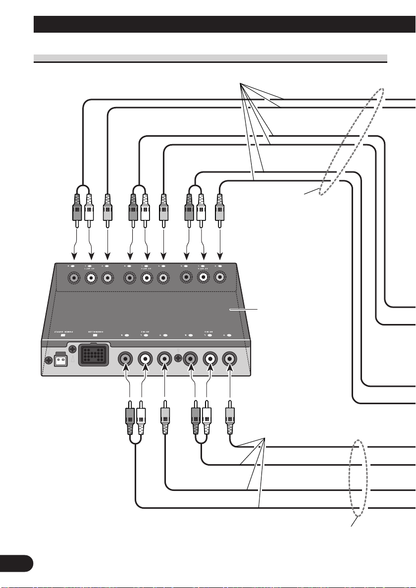
Page 5
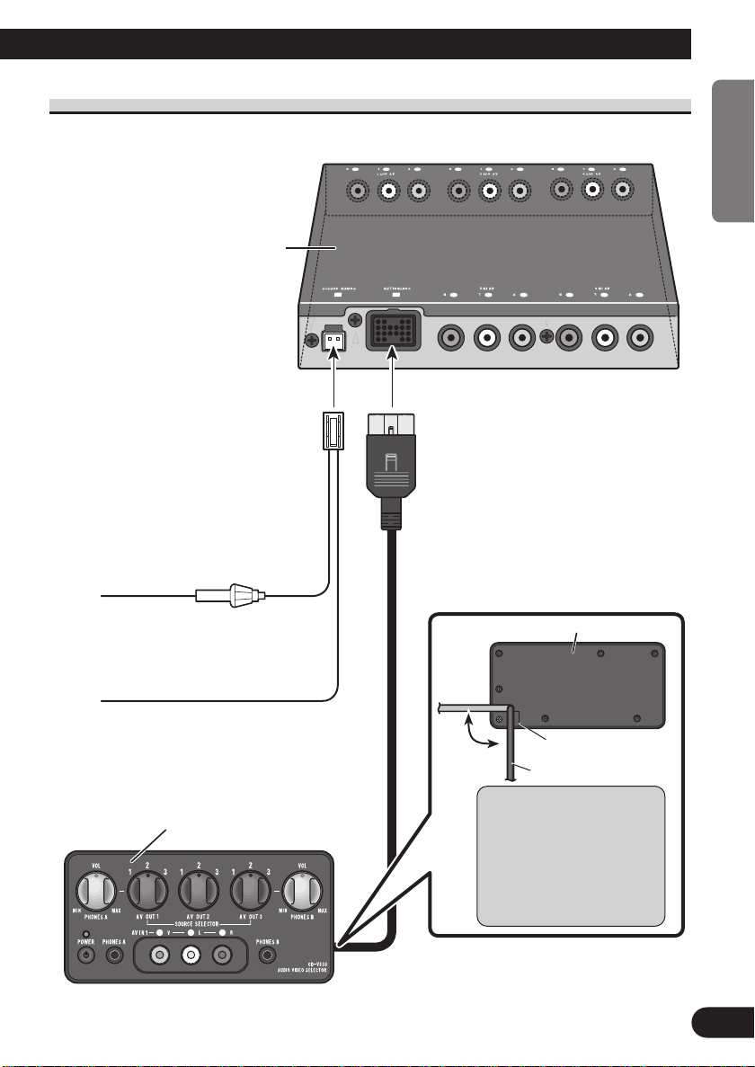
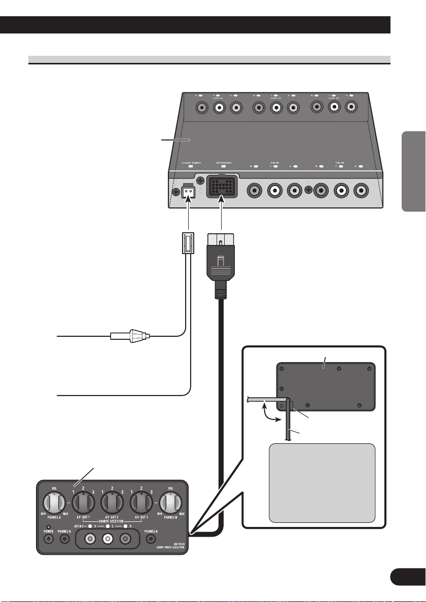
Connecting the Power Cord and Controller Unit
Hide-away unit
ENGLISH ESPAÑOL DEUTSCH FRANÇAIS
Fuse holder (1 A)
2 m
Red
To electric terminal controlled by
ignition switch (12V DC) ON/OFF.
2 m
Black (ground)
To vehicle (metal) body.
Controller unit
3 m
Controller unit rear side
ITALIANO NEDERLANDS
Groove
Cord
Route the controller unit
cord inside the slot groove
on the controller unit rear
side. Do not pull strongly,
excessively bend or stretch
the cord.
4
Page 6
Connecting the Units
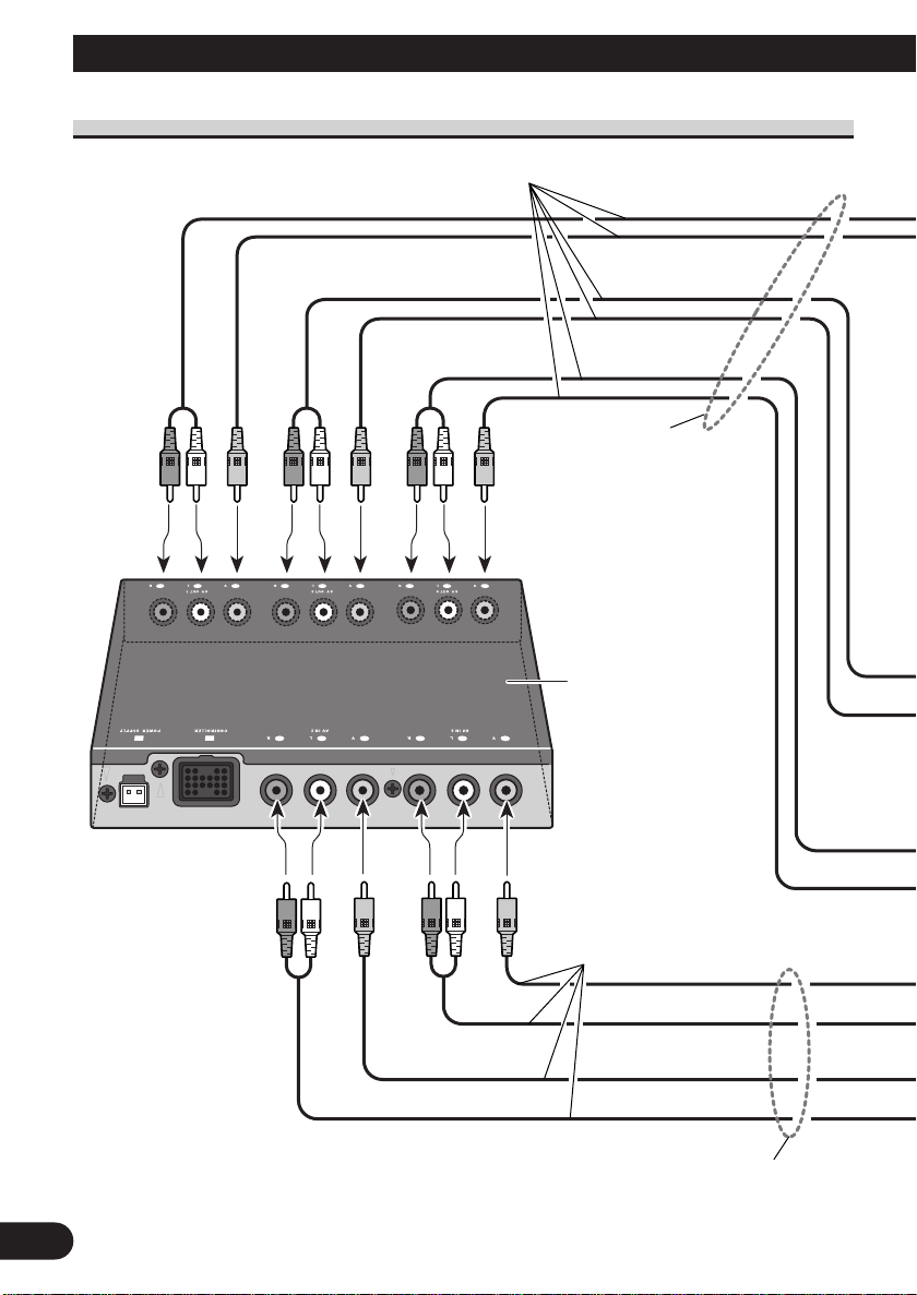
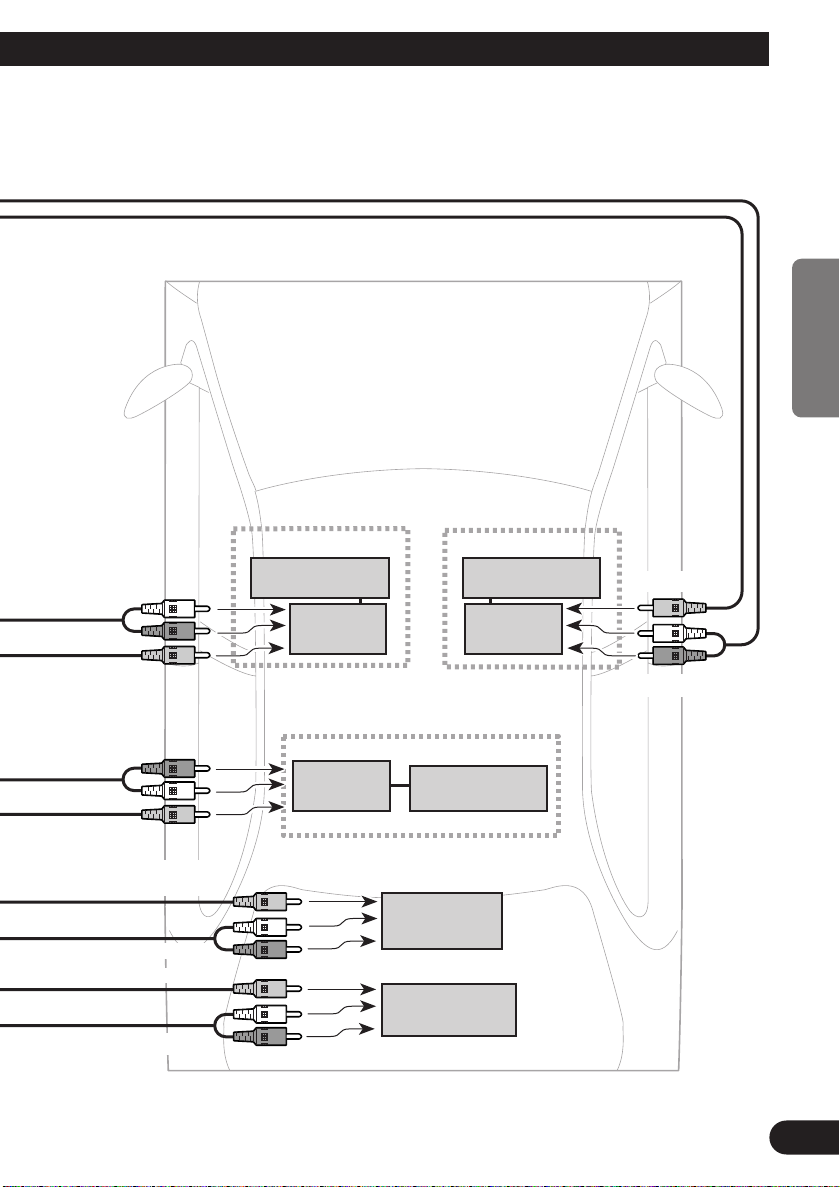
Connecting the System (1)
Connecting cords with RCA
pin plugs (sold separately)
AV OUT (1 – 3)
Hide-away unit
Connecting cords with RCA pin
plugs (sold separately)
AV IN (2 – 3)
5
Page 7
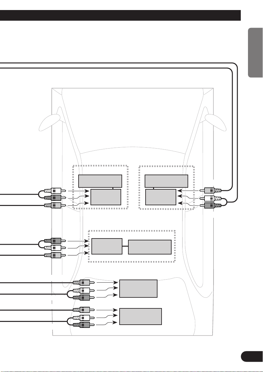
Front
ENGLISH ESPAÑOL DEUTSCH FRANÇAIS
Audio input
Video input
Audio input
Video input
Video output for rear
Audio output
Video output
Audio output
Rear Display 2
AVD-W8000, etc
Display Display
Hide-away
unit
Rear Display 3
AVD-W8000, etc
Hide-away
unit
Multi-DVD player
Portable video (sold
separately), etc
Rear Display 1
AVD-W8000, etc
Hide-away
Display
XDV-P9
Video input
unit
Audio input
ITALIANO NEDERLANDS
Rear
6
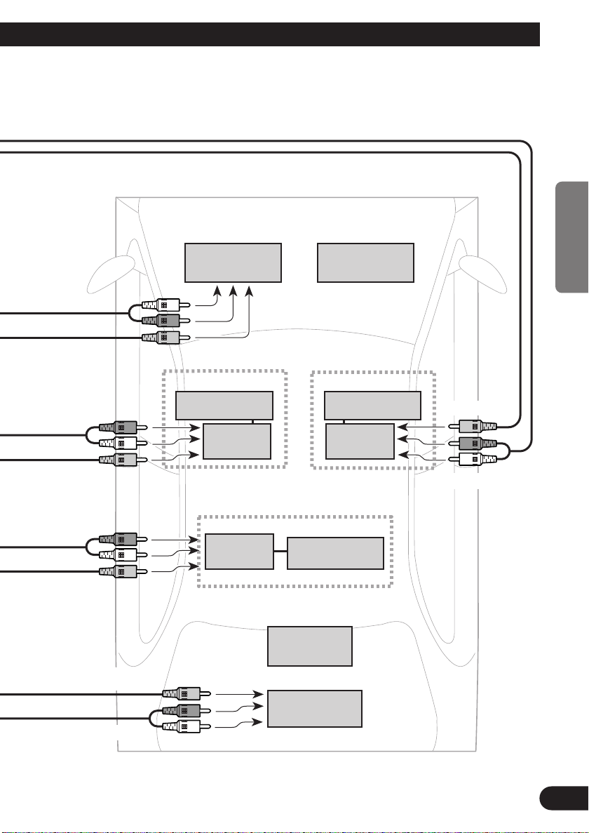
Page 8
A Title (English)
Connecting the Units
Connecting the System (2)
Connecting cords with RCA
pin plugs (sold separately)
AV OUT (1 – 3)
Hide-away unit
Connecting cords with RCA pin
plugs (sold separately)
AV IN (2 – 3)
7
Page 9
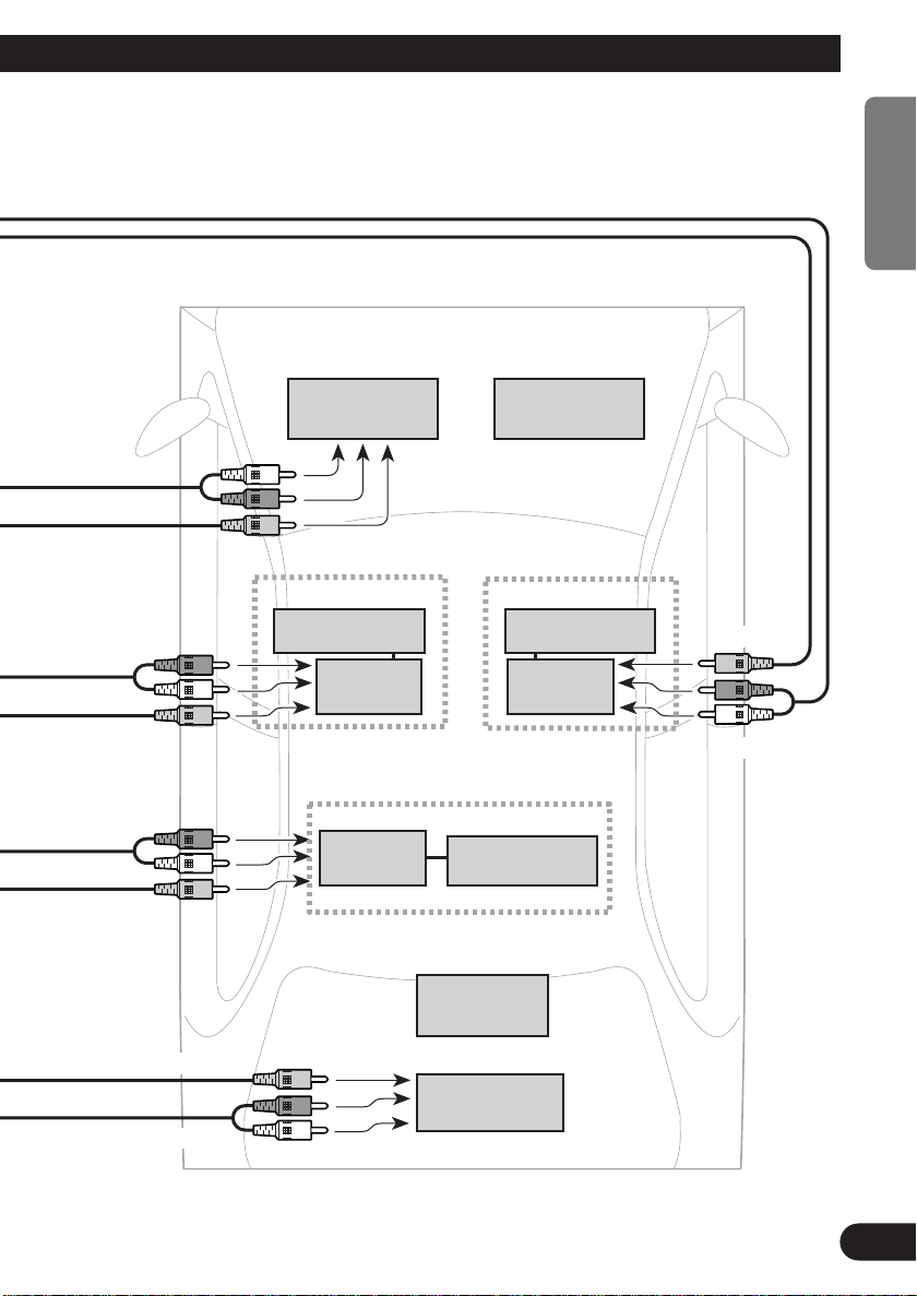
Front
ENGLISH ESPAÑOL DEUTSCH FRANÇAIS
Audio output
Video output
Audio input
Video input
Audio input
Video input
TV TUNER
GEX-P7000TV
Rear Display 2
AVD-W8000, etc
Display Display
Hide-away
unit
Rear Display 3
AVD-W8000, etc
Hide-away
unit
Front Display
AVX-P7000CD,
Rear Display 1
AVD-W8000, etc
Hide-away
Display
etc
Video input
unit
Audio input
ITALIANO NEDERLANDS
Video output for rear
Audio output
AVM-P9000R
Multi-DVD player
XDV-P9
Rear
8
Page 10
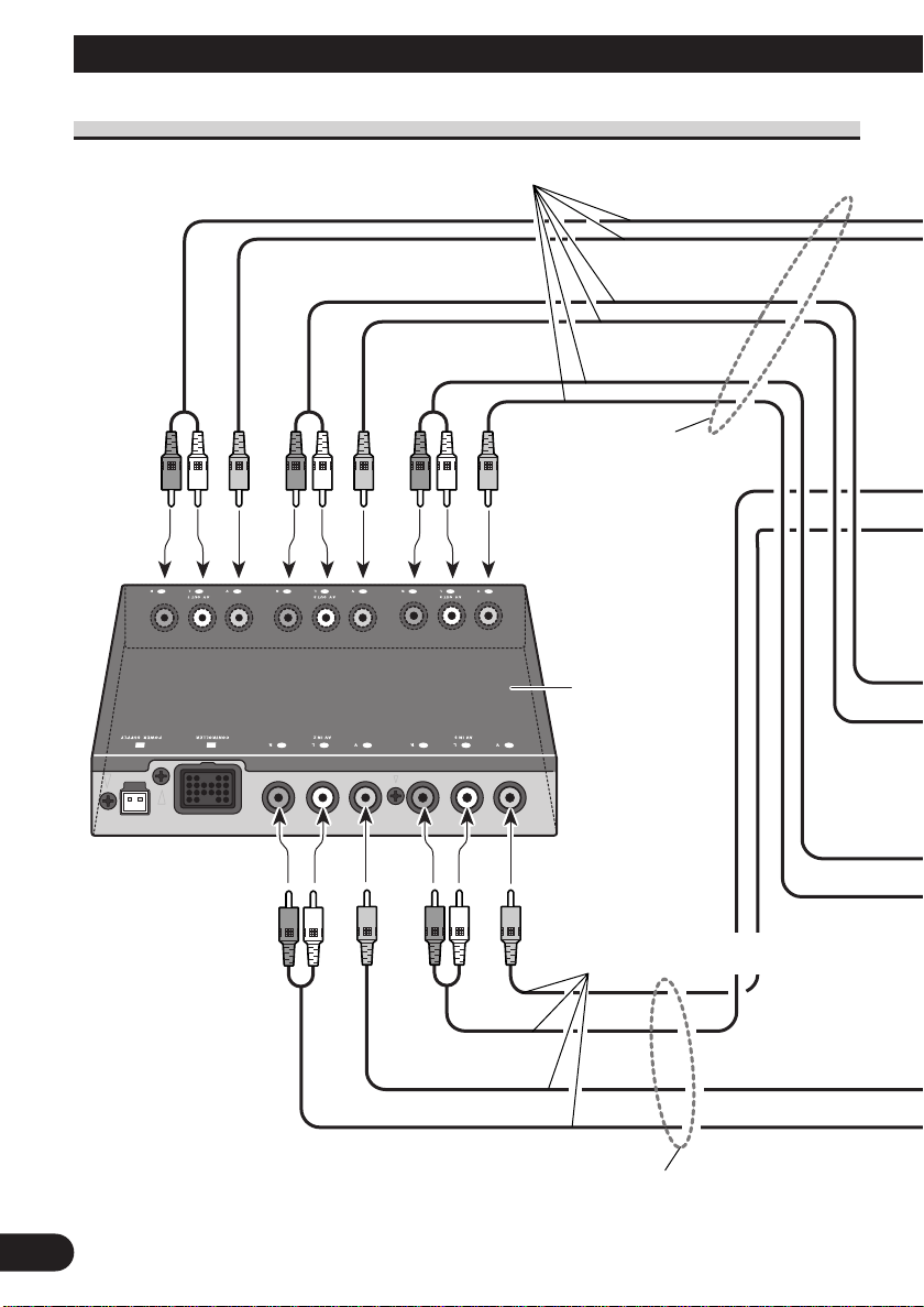
Connecting the Units
Connecting the Audio / Video equipment
Controller unit
∅ 3.5 mini pin plug
Headphones
(sold separately)
Video output
∅ 3.5 mini pin plug
Headphones
(sold separately)
Connecting cords with RCA
Connecting cords with RCA
pin plugs (sold separately)
pin plugs (sold separately)
Audio output
8mm video, vehicle-mounted
portable video, etc.
9
Page 11
Installation
Note:
• Before finally installing the unit, connect the wiring temporarily, making sure it is all connected up
properly, and the unit and the system work properly.
• Use only the parts included with the unit to ensure proper installation. The use of unauthorized
parts can cause malfunctions.
• Install the unit where it does not get in the driver’s way and cannot injure the passenger if there is a
sudden stop, like an emergency stop.
• When mounting this product, make sure none of the leads are trapped between this product and the
surrounding metalwork or fittings.
• Do not mount this product near the heater outlet, where it would be affected by heat, or near the
doors, where rainwater might splash onto it.
• If this product is installed in the passenger compartment, anchor it securely so it does not break free
while the car is moving, and cause injury or an accident.
• If this product is installed under a front seat, make sure it does not obstruct seat movement. Route
all leads and cords carefully around the sliding mechanism so they do not get caught or pinched in
the mechanism and cause a short circuit.
• Install the controller in a safe place where it can be easily operated from the rear seat.
• Never install the controller on the dashboard where it will be exposed to the direct rays of the sun.
It could be damaged by high temperatures.
• In attaching L-fixtures to the controller unit with screws, be careful not to overtighten the screws or
tighten them slanted. An expanded screw hole might result, disabling attachment of the L-fixtures.
• The L-fixture can be bent to match the installation location.
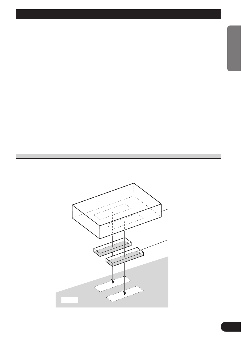
Installing Hide-away Unit
ENGLISH ESPAÑOL DEUTSCH FRANÇAIS
Car mat
Hide-away unit
ITALIANO NEDERLANDS
Velcro tape
(hard)
10
Page 12
Installation
Installing Controller Unit
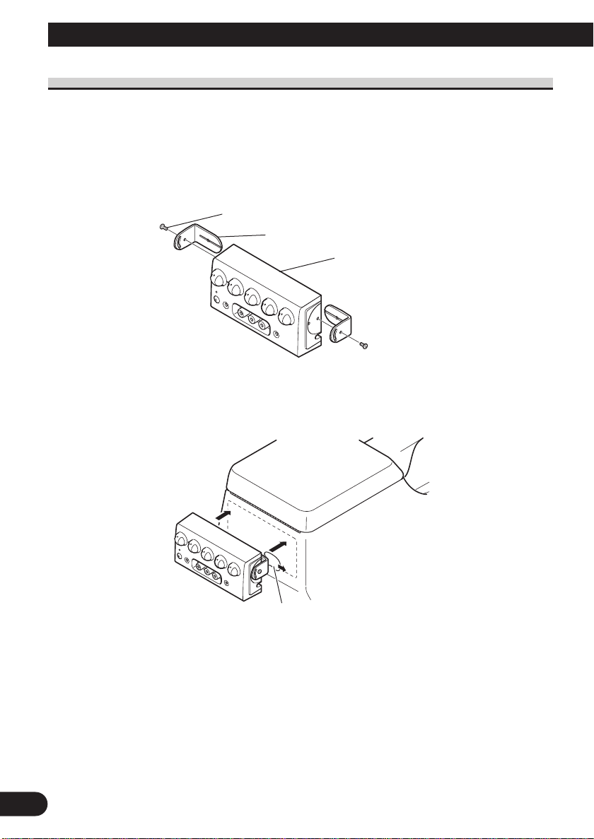
■ Installation using the L-fixture
The controller unit, when installed with L-fixtures, can be tilted for optimal ease of use.
Peel off the paper backing of the double-sided tape of the L-fixture and adhere to the
installation location.
1. Attach L-fixtures to the controller unit finger-tight.
Keep the screws loose.
Screw
L-fixture
Controller unit
2. Paste double-sided adhesive tape to the intended installation position of the
controller unit.
Remove release paper
Note:
• Bend the L-fixtures to meet the shape of the intended installation position of the controller unit.
11
Page 13
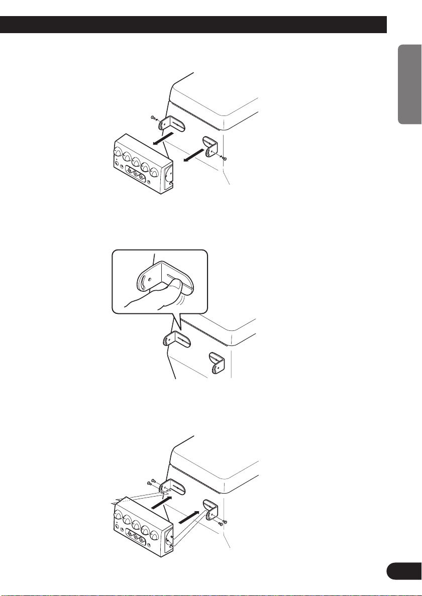
3. Release the controller unit from the L-fixtures once.
4. Press the L-fixtures firmly against the intended installation position of the
controller unit.
ENGLISH ESPAÑOL DEUTSCH FRANÇAIS
5. Attach the controller unit to the L-fixtures.
Keep the screws loose.
ITALIANO NEDERLANDS
12
Page 14
Installation
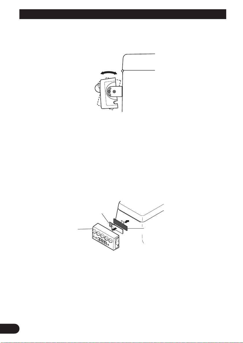
6. Adjust the installation angle of the controller unit.
Adjust the angle for optimal ease of use.
7. Secure the controller unit firmly with the L-fixtures.
Tighten the screws fully.
Note:
• Be careful not to overtighten the screws or tighten them slanted. An expanded screw hole might
result, disabling attachment of the L-fixtures.
■ Installation using Velcro tape
Adhere the Velcro tape (hard) (provided) to the back of the controller unit, adhere the
Velcro tape (soft) to the installation location and then install.
13
Controller unit
Velcro tape
(hard)
Velcro tape
(soft)
Page 15
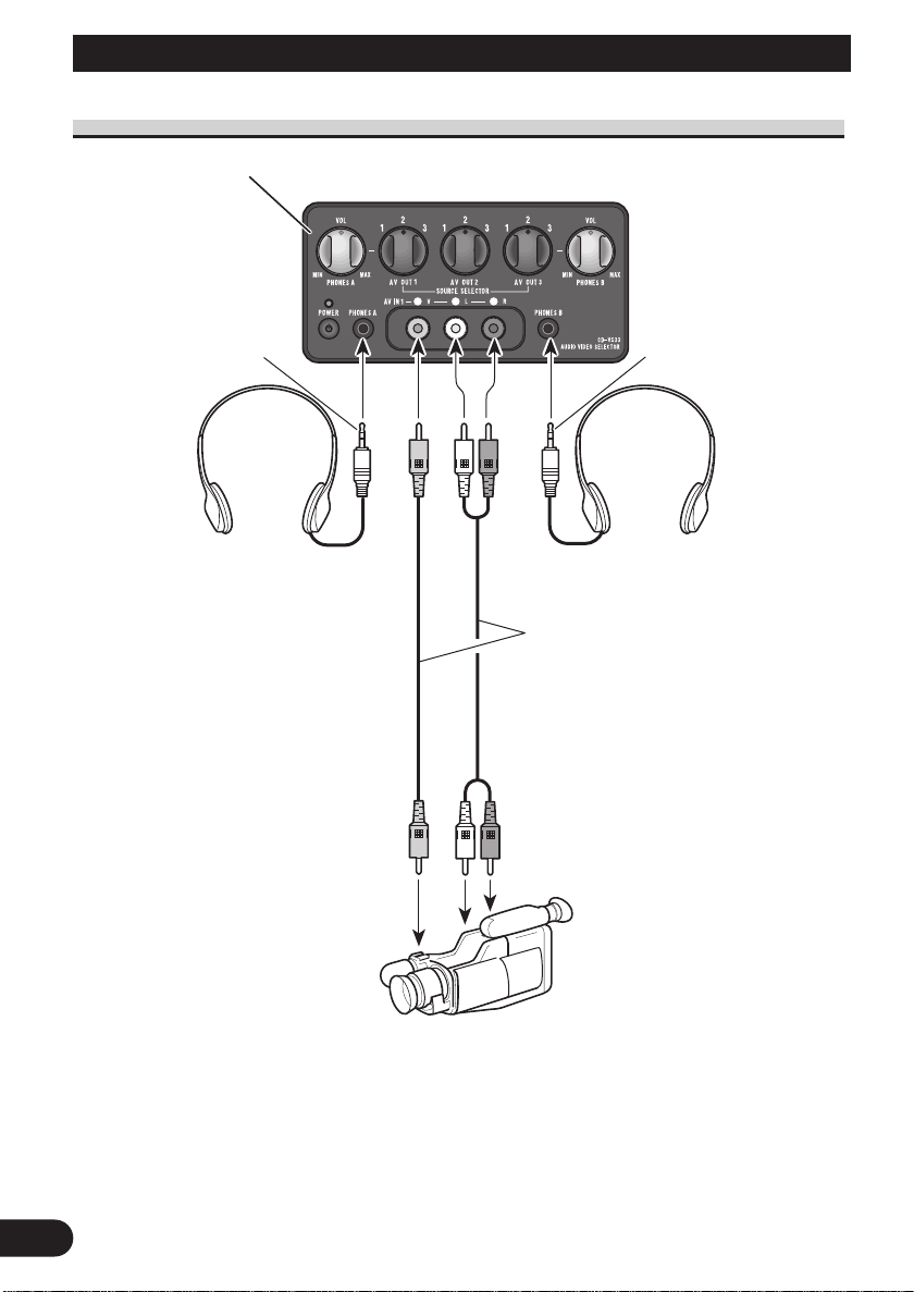
Part Names And Applications
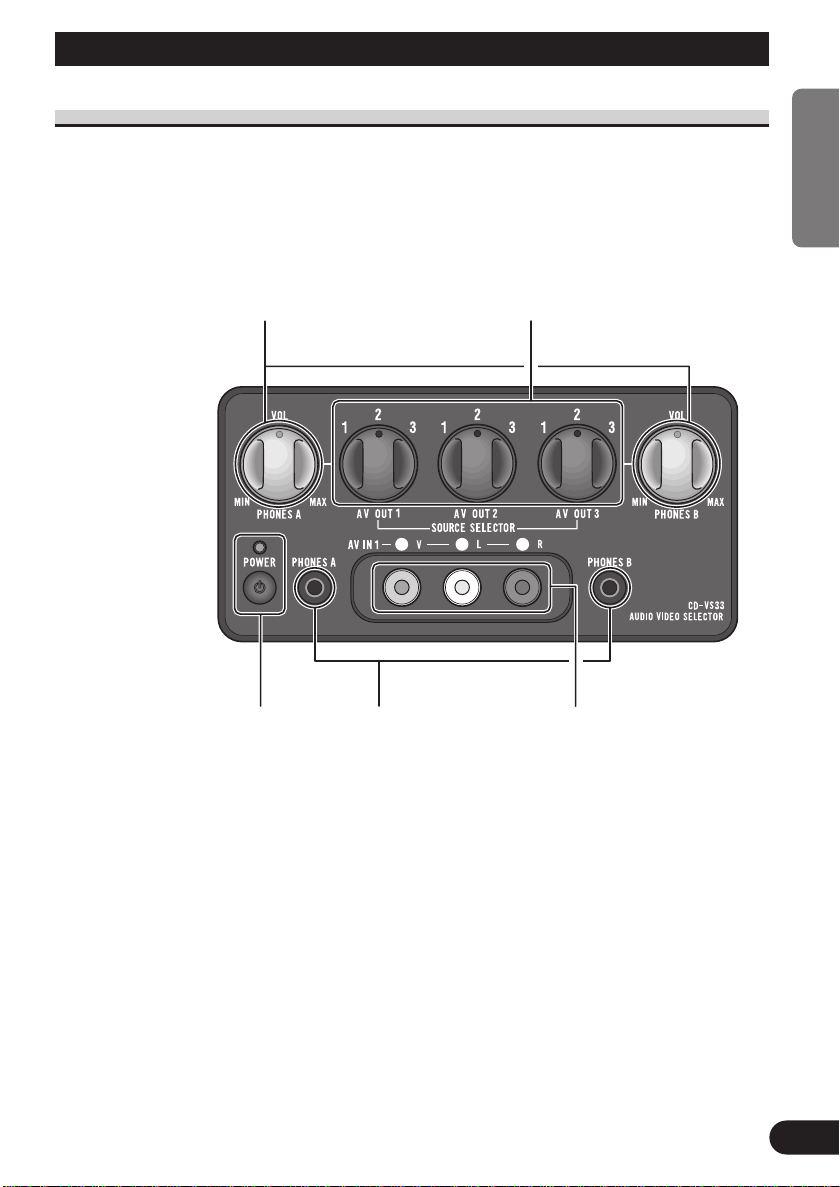
Controller Unit
VOLUME
PHONES A VOLUME is used to adjust the
volume of the headphones connected to
PHONES A.
PHONES B VOLUME is used to adjust the
volume of the headphones connected to
PHONES B.
Rotate counterclockwise to reduce the volume
and rotate clockwise to increase the volume.
ENGLISH ESPAÑOL DEUTSCH FRANÇAIS
SOURCE SELECTOR (1 – 3)
Used to switch the video and audio
connected to the AV IN jack (1 – 3)
for each AV OUT jack (1 – 3).
Power indicator, power
switch
The power is turned on or
off alternately each time
the power switch is
pressed. The power indicator lights when the
power is on.
Headphone output jacks
The mini pin plug of headphones
can be connected to PHONES A
or PHONES B.
The audio from AV OUT 1 is output from the headphones connected to PHONES A.
The audio from AV OUT 3 is output from the headphones connected to PHONES B.
AV IN jacks (1)
RCA video input (yellow)
RCA audio input (white,
red)
Used to connect 8mm
video, vehicle-mounted
portable video, etc.
ITALIANO NEDERLANDS
14
Page 16
Part Names And Applications
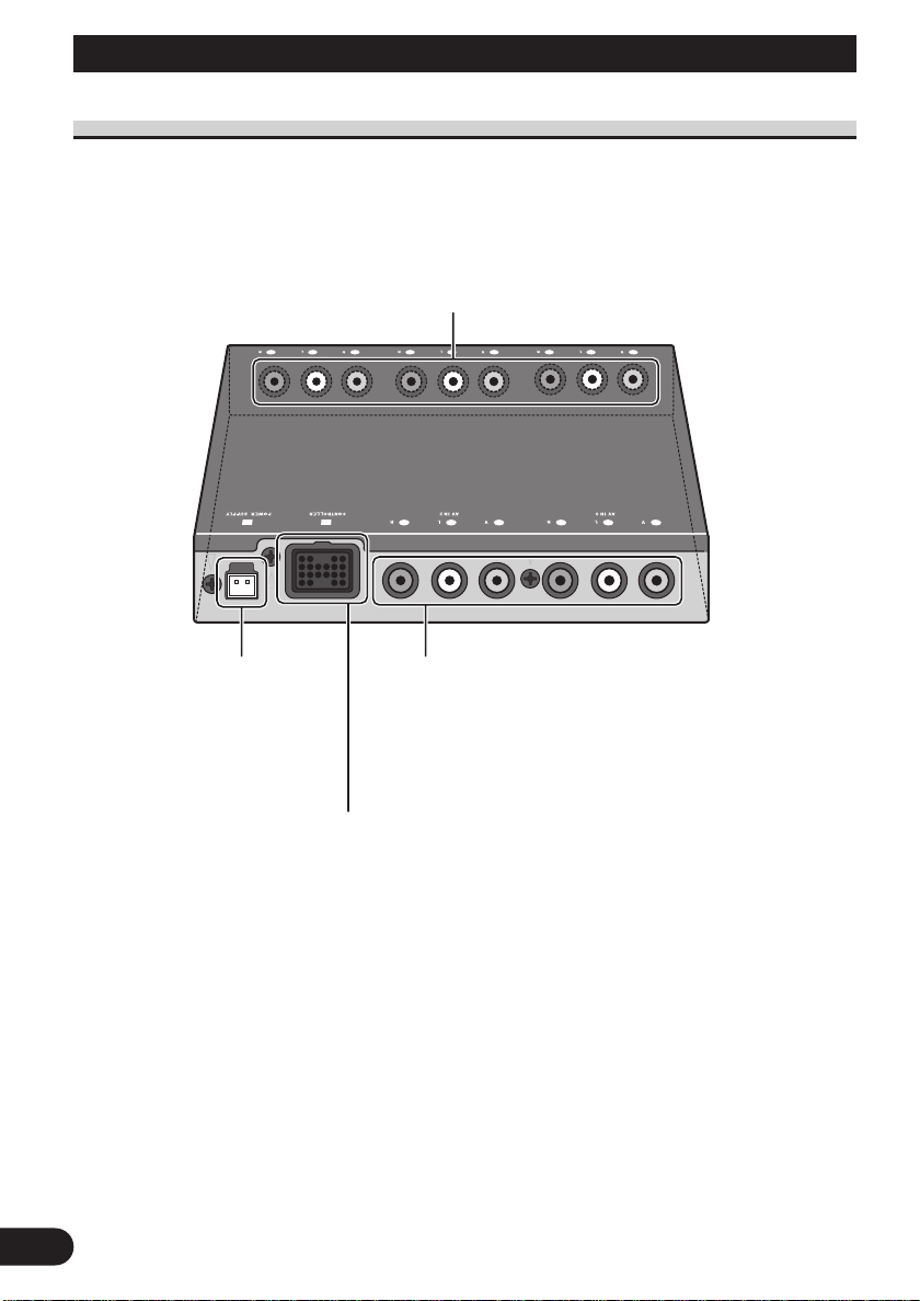
Hide-away Unit
AV OUT jacks (1 – 3)
RCA video output (yellow)
RCA audio output (white, red)
Outputs the video and audio signals (Multi-DVD
player, vehicle-mounted portable video, etc.)
connected to the AV IN jack.
15
Power
Connect the
power cord
(provided).
Controller connection jack
Connect the controller unit
(provided).
AV IN jacks (2 – 3)
RCA video input (yellow)
RCA audio input (white, red)
Used to connect to the RCA input jacks of video and
portable video units, etc.
Page 17

Specifications
Power Source .......................................................... 14.4 V
(10.8 – 15.1 V allowable)
Grounding System ...................................... Negative Type
Max. Current Consumption ...................................... 0.4 A
Audio Output Level ..........................................1Vp-p/75Ω
Hide-away Unit
Dimensions ............ 160 (W) × 28 (H) × 120 (D) mm
Weight ............................................................ 0.53 kg
Controller
Dimensions .............. 120 (W) × 60 (H) × 32 (D) mm
Weight ............................................................ 0.32 kg
Note:
• Specifications and the design are subject to possible modification without notice due to improvements.
ENGLISH
ENGLISH ESPAÑOL DEUTSCH FRANÇAIS
ITALIANO NEDERLANDS
16
Page 18

Indice
Antes de usar este producto .................... 2
Notas sobre este producto ................................ 2
Precaución ........................................................ 2
Conectando las unidades ........................ 3
Conexión del cable de alimentación y
del unidad controlador ................................ 4
Conexión del sistema (1) .................................. 5
Conexión del sistema (2) .................................. 7
Equipo de audio/vídeo........................................ 9
Instalación ................................................ 10
Instalación del unidad oculta-alejada .............. 10
Instalación del unidad controlador .................. 11
Nombre de las piezas y aplicaciones .. 14
Unidad controlador .......................................... 14
Unidad oculta-alejada ...................................... 15
Especificaciones .................................... 16
1
Page 19
Antes de usar este producto
Notas sobre este producto
Este producto es un selector de audio-vídeo para el asiento trasero que le permite conmutar
la pantalla entre audio y vídeo.
■ Cuando se usa este producto
Le recomendamos que se familizarice con las funciones y con su operación leyendo de
principio a fin el manual antes de comenzar a usar este producto. Es sumamente importante que lea y se fije en la “Precaución” en esta página siguiente y en las otras secciones.
Precaución
• Mantenga el manual a la mano para las referencias de los procedimientos de las
operaciones y las precauciones.
• Proteja este producto de la humedad.
• Cuando utilice los auriculares, evite ajustar a un nivel de volumen alto. La audición pro-
longada a altos niveles de volumen puede producir trastornos en el oído.
ADVERTENCIA
• Conecte el producto a una pantalla que no sea visible desde el asiento del conductor. Si
instala la pantalla en un sitio que sea visible por el conductor, escoja una que pueda
detectar el estado de aplicación/liberación del freno de estacionamiento, y asegúrese de
instalarla correctamente de manera que funcione siempre conjuntamente con el interruptor del freno de estacionamiento.
• Para evitar riesgos de accidentes y una eventual infracción de las leyes vigentes, este
producto no es para usar con pantalla de vídeo visible desde el asiento del conductor.
• En algunos países o estados, el mirar imágenes en pantalla dentro de un vehículo puede
ser ilegal no sólo para el conductor, sino para todos los ocupantes. Respete estos
reglamentos cuando sean aplicables.
ENGLISH
ESPAÑOL DEUTSCH FRANÇAIS
ITALIANO NEDERLANDS
2
Page 20

Conectando las unidades
Nota:
• Este producto es para vehículos con batería de 12 voltios y con conexión a tierra. Antes de instalar
la unidad en un vehículo recreativo, camioneta, o autobús, revise el voltaje de la batería.
• Para evitar cortocircuitos en el sistema eléctrico, asegúrese de desconectar el cable de la batería ≠
antes de comenzar con la instalación.
• Luego de completar la instalación y cableado, realice una doble verificación para cerciorarse de que
no hay errores. Vuelva a instalar las partes retiradas del automóvil durante la instalación, luego
conecte el terminal negativo de la batería.
• Refiérase al manual del propietario para los detalles acerca de la conexión de los variados cables
del amplificador de potencia y otras unidades, luego realice las conexiones correctamente.
• Asegure el cableado con abrazaderas de cables o con cinta adhesiva. Para proteger el cableado,
envuélvalo con cinta adhesiva donde éstos se apoyan sobre las piezas de metal.
• Coloque y asegure todo el cableado de tal manera que no toque las piezas en movimiento, tal como
la palanca de cambio de velocidades, el freno de mano, y los pasamanos de los asientos.
No coloque el cableado en lugares que se calientan, tal como cerca de la salida de un calefactor. Si
el material aislante del cableado se derritiera o se gastara, habrá el peligro de un cortocircuito del
cableado a la carrocería del vehículo.
• No acorte ninguna guía. Si lo hiciera, la protección del circuito podría fallar al funcionar cuando
debería.
• Nunca alimente energía a otros equipos cortando el aislamiento de la guía de alimentación provista
de la unidad y haciendo un empalme con la guía. La capacidad de corriente de la guía se excederá,
causando el recalentamiento.
• Cuando reemplace algún fusible, asegúrese de utilizar solamente un fusible del ratio descrito en el
soporte de fusibles.
• Sujete siempre el unidad controlador cuando conecte una clavija RCA.
3
Page 21
Conexión del cable de alimentación y del unidad controlador
ENGLISH
Unidad ocultaalejada
Porta fusible (1 A)
2 m
Rojo
Al terminal de energía eléctrica controlado por el interruptor de encendido
del vehículo (12 V C.C.) ON/OFF.
2 m
Negro (tierra)
A la carrocería (metálica) del vehículo
(parte metálica).
ESPAÑOL DEUTSCH FRANÇAIS
3 m
Lado trasero del controlador
ITALIANO NEDERLANDS
Ranura
Cable
Unidad controlador
Tienda el cable del controlador dentro de la ranura dispuesta en la parte posterior
del controlador. No tire del
cordón con fuerza y evite
doblarlo o atirantarlo excesivamente.
4
Page 22
Conectando las unidades
Conexión del sistema (1)
Cables de conexión con clavjás
RCA (en venta por separado).
AV OUT (1–3)
Unidad oculta-alejada
Cables de conexión con clavjás
RCA (en venta por separado).
AV IN (2–3)
5
Page 23
Parte delantera
ENGLISH
ESPAÑOL DEUTSCH FRANÇAIS
Entrada de audio
Entrada de vídeo
Entrada de audio
Entrada de vídeo
Salida de vídeo para la
parte trasera
Salida de audio
Salida de vídeo
Salida de audio
Pantalla trasera 2
AVD-W8000, etc
Pantalla Pantalla
Unidad oculta-
alejada
Pantalla trasera 3
AVD-W8000, etc
Unidad oculta-
alejada
Reproductor de
Vídeo portátil (en
venta por separa-
Pantalla trasera 1
AVD-W8000, etc
Unidad oculta-
Pantalla
Multi-DVD
XDV-P9
do), etc.
Entrada de vídeo
alejada
Entrada de audio
ITALIANO NEDERLANDS
Parte trasera
6
Page 24

Conectando las unidades
Conexión del sistema (2)
Cables de conexión con clavjás
RCA (en venta por separado).
AV OUT (1–3)
Unidad ocultaalejada
Cables de conexión con clavjás
RCA (en venta por separado).
AV IN (2–3)
7
Page 25
Parte delantera
ENGLISH
ESPAÑOL DEUTSCH FRANÇAIS
Salida de audio
Salida de vídeo
Entrada de audio
Entrada de vídeo
Entrada de audio
Entrada de vídeo
Sintonizador de TV
GEX-P7000TV
Pantalla trasera 2
AVD-W8000, etc
Pantalla Pantalla
Unidad oculta-
alejada
Pantalla trasera 3
AVD-W8000, etc
Unidad oculta-
alejada
Pantalla delantera
AVX-P7000CD, etc
Pantalla trasera 1
AVD-W8000, etc
Unidad oculta-
Pantalla
Entrada de vídeo
alejada
Entrada de audio
ITALIANO NEDERLANDS
Salida de vídeo para la
parte trasera
Salida de audio
AVM
-P9000R
Reproductor de
Multi-DVD
XDV-P9
Parte trasera
8
Page 26

Conectando las unidades
Equipo de audio/vídeo
Unidad Controlador
Miniclavija
monopolar de
∅ 3,5
Auriculares (en
venta por sepa-
rado)
Salida de vídeo
Miniclavija
monopolar de ∅ 3,5
Auriculares (en
venta por sepa-
rado)
Cables de conexión con
clavjás RCA (en venta por
separado)
Salida de audio
Vídeo de 8 mm, vídeo
portátil montado en
vehículo, etc.
9
Page 27

Instalación
Nota:
• Antes de instalar finalmente la unidad, conecte el cableado temporariamente y asegúrese de que
todas las conexiones están correctas y que la unidad funciona adecuadamente.
• Utilice solamente las partes incluidas con la unidad para asegurar una instalación adecuada. El uso
de partes no autorizadas pueden ocasionar fallas de funciona-miento.
• Instale la unidad en un lugar en donde no interfiera con el conductor y no pueda lesionar a los
pasajeros en caso de una parada repentina, tal como una al frenar por una emergencia.
• Al colocar este producto, asegúrese de que ninguno de los conductores quede atrapado entre este
producto y las partes metálicas circundantes o dispositivos.
• No coloque este producto cerca de la salida de calefacción, en donde podría ser afectada por el
calor, o cerca de las puertas, en donde el agua de lluvia podría salpicarla.
• Si este producto es instalada en el compartimiento del pasajero, fíjela adecuadamente de modo que
no se mueva libremente cuando el automóvil se encuentra en movimiento, pudiendo ocasionar
lesiones o accidentes.
• Si este producto es instalada debajo de un asiento delantero, asegúrese de que no obstruya el
movimiento del asiento. Disponga todos los cables y conductores cuidadosamente alrededor del
mecanismo deslizante de modo que no queden atrapados o aprisionados en el mecanismo a causa
de un cortocircuito.
• Instale el unidad controlador en un lugar seguro, de forma que pueda ser fácilmente accionado
desde el asiento trasero.
• No instale nunca el controlador en el tablero de instrumentos o donde pueda quedar expuesto a los
rayos directos del sol, pues podría dañarse debido a las altas temperaturas.
• Cuando apriete los tornillos para fijar los sujetadores L al controlador, preste atención para no apretarlos en exceso o de forma inclinada. De lo contrario, puede suceder que los agujeros de los tornillos se ensanchen y que no se puedan fijar los sujetadores L.
• El sujetador L puede doblarse para adaptarlo al sitio de instalación.
Instalación del unidad oculta-alejada
ENGLISH
ESPAÑOL DEUTSCH FRANÇAIS
Alfombra del
automóvil
Unidad oculta-alejada
ITALIANO NEDERLANDS
Cinta autoadhesiva
(rígida)
10
Page 28

Instalación
Instalación del unidad controlador
■ Instalación utilizando el sujetador L
Para una óptima facilidad de empleo, instale el controlador con los sujetadores L.
Despegue el papel del dorso de la cinta de doble cara del sujetador L y péquela en el sitio
de instalación.
1. Fije los sujetadores L al unidad controlador apretándolos con los dedos.
Mantenga los tornillos flojos.
2. Pegue la cinta adhesiva de doble cara en el sitio de instalación previsto para
el unidad controlador.
Tornillo
Sujetador L
Unidad Controlador
Despegar la tira desprendible
Nota:
• Doble los sujetadores L para acomodarlos a la forma del lugar de instalación previsto
para el unidad controlador.
11
Page 29

3. Retire los sujetadores del unidad controlador.
4. Presione firmemente los sujetadores L contra el sitio de instalación previsto
para el unidad controlador.
ENGLISH
ESPAÑOL DEUTSCH FRANÇAIS
5. Fije el unidad controlador a los sujetadores L.
Mantenga los tornillos flojos.
ITALIANO NEDERLANDS
12
Page 30

Instalación
6. Ajuste el ángulo de instalación del unidad controlador.
Ajuste el ángulo para una óptima facilidad de empleo.
7. Asegure firmemente el unidad controlador con los sujetadores L.
Apriete los tornillos firmemente.
Nota:
• Preste atención para no apretar los tornillos en exceso o de forma inclinada. De lo contrario, puede
suceder que los agujeros de los tornillos se ensanchen y que no se puedan fijar los sujetadores L.
■ Instalación utilizando la cinta velcro
Pegue la cinta Velcro (rígida) suministrada sobre la parte posterior del unidad controlador
y la cinta Velcro (blanda) sobre el sitio de instalación y realice la instalación.
13
Unidad
controlador
Cinta Velcro
(rígida)
Cinta Velcro
(blanda)
Page 31

Nombre de las piezas y aplicaciones
Unidad controlador
VOLUME
PHONE A VOLUME se utiliza para ajustar el volumen de los auriculares conectados a PHONES A.
PHONES B VOLUME se utiliza para ajustar el volumen de los auriculares conectados a PHONES B.
Gire en sentido contrario a las agujas del reloj para
disminuir el volumen y en el sentido de las agujas
del reloj para aumentarlo.
SELECTOR DE FUENTE (1-3)
Se utiliza para conmutar el vídeo y
audio conectados a la toma AV IN
(1-3) para cada toma AV OUT (1-3).
ENGLISH
ESPAÑOL DEUTSCH FRANÇAIS
Indicador de alimentación,
interruptor de alimentación
La unidad se enciende y
apaga alternativamente cada
vez que presiona el interruptor de alimentación. Al encen-
der la unidad, el indicador de
alimentación se ilumina.
Tomas de salida para auriculares
La miniclavija macho de los auriculares puede conectarse a PHONES A
o PHONES B.
El audio de AV OUT 1 sale por los
auriculares conectados a PHONES A.
El audio de AV OUT 3 sale de los
auriculares conectados a PHONES B.
Tomas AV IN (1)
Entrada de vídeo RCA
(amarillo), entrada de
audio RCA (blanco, rojo)
Se utiliza para conectar un
vídeo de 8 mm, un vídeo
portátil montado en el
vehículo, etc.
ITALIANO NEDERLANDS
14
Page 32

Nombre de las piezas y aplicaciones
Unidad oculta-alejada
Tomas AV OUT (1 – 3)
Salida de vídeo RCA (amarillo)
Salida de audio RCA (blanco, rojo)
Salidas de las señales de audio y vídeo de las
unidades (Reproductor de Multi-DVD, vídeo
portátil montado en el vehículo, etc.) conectadas
a la toma AV IN.
15
Alimentación
Se utiliza para
conectar el cable
de alimentación
suministrado.
Toma para conexión del
unidad controlador
Conecte el unidad controlador suministrado.
Tomas AV IN (2 – 3)
Entrada de vídeo RCA (amarillo)
Entrada de audio RCA (blanco, rojo)
Se utiliza para conectar las tomas de entrada de RCA
de vídeo con unidades de vídeo portátiles, etc.
Page 33

Especificaciones
Fuente de alimentación .................................... 14,4 V CC
Sistema de conexión a tierra .................. De tipo negativo
Máx. consumo de energía .......................................... 0,4 A
Nivel de Salida de Audio .............................. 1 Vp-p/75
Unidad oculto-alejado
Dimensiones ........ 160 (An)
Peso ................................................................ 0,53 kg
Unidad controlador
Dimensiones .......... 120 (An)
Peso ................................................................ 0,32 kg
(10,8 – 15,1 V permisible)
Ω
× 28 (Al) × 120 (Pr) mm
× 60 (Al) × 32 (Pr) mm
Nota:
• Las especificaciones y el diseño están sujetos a
posibles modificaciones sin previo aviso debido a
mejoramientos.
ENGLISH
ESPAÑOL DEUTSCH FRANÇAIS
ITALIANO NEDERLANDS
16
Page 34

Inhaltsverzeichnis
Vor Inbetriebnahme .................................. 2
Über dieses Produkt .......................................... 2
Vorsichtsmaßnahmen ........................................ 2
Anschließen der Geräte .......................... 3
Anschließen des Stromkabels und des
Controllers- Einheit ....................................4
Anschließen der Geräte (1) .............................. 5
Anschließen der Geräte (2) .............................. 7
Anschließen der Audio/Video-Geräte................9
Einbau ........................................................ 10
Einbauen des Steuerungsgeräts ...................... 10
Einbauen des Controllers-Einheit .................... 11
Bezeichnung der Teile und ihre
Funktionen .......................................... 14
Controllers-Einheit .......................................... 14
Hideaway-Einheit ............................................ 15
Technische Daten .................................... 16
1
Page 35

Vor Inbetriebnahme
Über dieses Produkt
Dieses Gerät ist ein Rücksitz-Audio-Video-Selektor, der die Umschaltung zwischen Audio
und Video des Displays ermöglicht.
■ Bei Gebrauch dieses Produit
Wir empfehlen, daß Sie sich mit den Funktionen und der Bedienung des Geräts vertraut
machen, indem Sie dieses Handbuch sorgfältig lesen, bevor Sie das Gerät in Betrieb
nehmen. Achten Sie insbesondere auf den Text unter “Vorsichtsmaßnahmen” auf diese
Seite und in anderen Abschnitten.
Vorsichtsmaßnahmen
• Bewahren Sie dieses Bedienungsanleitung sorgfältig auf, damit Sie jederzeit nachschla-
gen können.
• Achten Sie darauf, daß diese Anlage keiner Feuchtigkeit ausgesetzt wird.
• Stellen Sie bei Verwendung eines Kopfhörers keinen hohen Lautstärkepegel ein.
Abhören mit hoher Lautstärke über längere Zeitspannen kann schädlich für das Gehör
sein.
WARNUNG
• Schließen Sie das Produkt an ein Display an, das nicht vom Fahrer einsehbar ist. Falls
das Display nur an einer Stelle installiert werden kann, wo es vom Fahrer einsehbar ist,
verwenden Sie ein Display, das den EIN/AUS-Zustand der Feststellbremse erkennen
kann, und installieren Sie das Display korrekt, so dass es immer in Verbindung mit dem
Feststellbremsschalter funktioniert.
• Zur Vermeidung von Unfällen und zur Einhaltung der entsprechenden
Gesetzesvorschriften darf dieses Produkt nicht mit einem für den Fahrer sichtbaren
Videobildschirm verwendet werden.
• In einigen Ländern oder Staaten ist auch Bei- und Mitfahrern in einem Fahrzeug das
Betrachten von Bildern auf einem Bildschirm verboten. Wo solche Vorschriften gelten,
sind diese zu beachten.
ENGLISH ESPAÑOL
DEUTSCH FRANÇAIS
ITALIANO NEDERLANDS
2
Page 36

Anschließen der Geräte
Hinweis:
• Dieses Produkt ist für Fahrzeuge mit 12-V-Batterie und negativer Erdung konzipiert. Bevor Sie es
in ein Freizeitfahrzeug, einen LKW oder Bus einbauen, müssen Sie die Batteriespannung überprüfen.
• Um Kurzschlüsse beim elektrischen System zu vermeiden, unbedingt das Massekabel ≠ der
Batterie abklemmen, bevor mit der Installation begonnen wird.
• Nach vollständiger Installation und Verkabelung sollten Sie sicherstellen, daß keine Fehler begangen worden sind. Bauen Sie alle Teile, die Sie während der Installation ausgebaut haben, wieder
ein, und schließen Sie dann das Massekabel der Batterie wieder an.
• Einzelheiten zum Anschluß der verschiedenen Kabel des Leistungsverstärkers und anderer Geräte
entnehmen Sie bitte den entsprechenden Bedienungsanleitungen, und nehmen Sie die Anschlüsse
richtig vor.
• Sichern Sie die Kabel mit Kabelklemmen oder Klebeband. Zum Schutz der Kabel umwickeln Sie
diese an Berührungsstellen mit Metallteilen mit Klebeband.
• Verlegen und sichern Sie alle Kabel so, daß diese keine beweglichen Teile, wie z.B. Schalthebel,
Handbremse und Sitzschienen, berühren können. Verlegen Sie Kabel nicht an Stellen, die heiß werden können, wie z.B. in der Nähe des Heizungsauslasses. Falls eine Kabelisolierung schmilzt oder
rissig wird, besteht die Gefahr eines Kurzschlusses zwischen Kabel und Karosseriemasse.
• Schließen Sie kein Kabel kurz, da anderenfalls die Schutzschaltung ausfallen kann, wenn sie in
Kraft treten sollte.
• Führen Sie niemals Strom anderen Geräten zu, indem Sie das Stromversorgungskabel des Geräts
abisolieren und es mit einem anderen Kabel verbinden, da dadurch die Belastbarkeit des Kabels
überschritten und Überhitzung verursacht wird.
• Wenn eine Sicherung ausgewechselt wird, unbedingt eine solche mit dem auf dem Sicherungshalter
angegebenen Nennwert verwenden.
• Halten Sie stets den Controllers-Einheit fest, wenn Sie einen Cinch-Stecker anschließen.
3
Page 37

Anschließen des Stromkabels und des Controllers- Einheit
Hideaway-Einheit
ENGLISH ESPAÑOL
DEUTSCH FRANÇAIS
Sicherungshalter (1 A)
2 m
Rot
An eine Stromversorgung anschließen,
(12 V Gleichstrom), die mit dem
Zündschloß ein- und ausgeschaltet wird.
Schwarz (Erdung)
An die Karosserie (Metallteil)
anschließen.
Controllers-Einheit
2 m
3 m
Controller-Rückseite
ITALIANO NEDERLANDS
Rille
Kabel
Führen Sie das Kabel des
Controllers durch die
Schlitznut auf der
Rückseite des Controllers.
Das Kabel nicht gewaltsam
ziehen, übermäßig biegen
oder dehnen.
4
Page 38

Anschließen der Geräte
Anschließen der Geräte (1)
Verbindungskabel mit RCAStiftstecker (getrennt erhältlich)
AV OUT (1 – 3)
Hideaway-Einheit
Verbindungskabel mit RCAStiftstecker (getrennt erhältlich)
AV IN (2 – 3)
5
Page 39

Vorn
ENGLISH ESPAÑOL
DEUTSCH FRANÇAIS
Audio-Eingang
Video-Eingang
Audio-Eingang
Video-Eingang
Video-Ausgang für hinten
Audio-Ausgang
Video-Ausgang
Audio-Ausgang
Hinteres Display 2
AVD-W8000, u.s.w.
Display Display
Hideaway-
Einheit
Hinteres Display 3
AVD-W8000, u.s.w.
Hideaway-
Einheit
Multi-DVD player
Tragbares Videoerhältlich), u.s.w.
Hinteres Display 1
Display
XDV-P9
gerät (getrennt
AVD-W8000, u.s.w.
Hideaway-
Einheit
VideoEingang
AudioEingang
ITALIANO NEDERLANDS
Hinten
6
Page 40

Anschließen der Geräte
Anschließen der Geräte (2)
Verbindungskabel mit RCAStiftstecker (getrennt erhältlich)
AV OUT (1 – 3)
Hideaway-Einheit
Verbindungskabel mit RCAStiftstecker (getrennt erhältlich)
AV IN (2 – 3)
7
Page 41

Vorn
ENGLISH ESPAÑOL
Audio-Ausgang
Video-Ausgang
Audio-Eingang
Video-Eingang
Audio-Eingang
Video-Eingang
Fernsehtuner
GEX-P7000TV
Hinteres Display 2
AVD-W8000, u.s.w.
Display Display
Hideaway-
Einheit
Hinteres Display 3
AVD-W8000, u.s.w.
Hideaway-
Einheit
Vorderes Display
AVX-P7000CD,
Hinteres Display 1
AVD-W8000, u.s.w.
Hideaway-
Display
u.s.w
DEUTSCH FRANÇAIS
VideoEingang
Einheit
AudioEingang
ITALIANO NEDERLANDS
Video-Ausgang für hinten
Audio-Ausgang
AVM-P9000R
Multi-DVD player
XDV-P9
Hinten
8
Page 42

Anschließen der Geräte
Anschließen der Audio / Video-Geräte
ControllersEinheit
∅ 3,5 Mini-Klinkenstecker
Kopfhörer
(getrennt
erhältlich)
Video-Ausgang
∅ 3,5 Mini-Klinkenstecker
Kopfhörer
(getrennt
erhältlich)
Verbindungskabel mit RCAStiftstecker (getrennt erhältlich)
Audio-Ausgang
8-mm-Video-Gerät, tragbares
Bord-Videogerät usw.
9
Page 43

Einbau
Hinweis:
• Bevor Sie das Gerät endgültig einbauen, schließen Sie die Kabel provisorisch an, und überzeugen
Sie sich, daß alle Anschlüsse stimmen, und daß das ganze System richtig funktioniert.
• Verwenden Sie für den Einbau nur die mitgelieferten Teile. Durch den Gebrauch von ungeeigneten
Teilen können Betriebsstörungen verursacht werden.
• Installieren Sie die Anlage so, daß sie den Fahrer nicht stört und keinen Mitfahrer verletzen kann,
z.B. im Falle einer Notbremsung.
• Achten Sie bei der Befestigung dieses Geräts darauf, daß kein Kabel zwischen irgendwelchen
Teilen eingeklemmt werden kann.
• Bringen Sie dieses Gerät nicht in der Nähe des Heizungsauslasses an, wo es durch die
Wärmeabstrahlung beeinträchtigt werden könnte, oder in der Nähe der Türen, wo es Feuchtigkeit
ausgesetzt werden könnte.
• Wenn dieses Gerät im Fahrgastraum installiert wird, muß es sicher befestigt werden, so daß es sich
während der Fahrt nicht lösen und Verletzungen oder einen Unfall verursachen kann.
• Wenn dieses Gerät unter einem Vordersitz installiert wird, muß sichergestellt werden, daß der Sitz
immer noch ohne jegliche Behinderung verschoben werden kann. In diesem Fall sind jegliche
Kabel sorgfältig so um den Verschiebemechanismus zu verlegen, daß sie nicht eingeklemmt werden und einen Kurzschluß verursachen können.
• Bringen Sie den Controller an einem geeigneten Platz an, wo er bequem vom Rücksitz aus bedient
werden kann.
• Montieren Sie den Controller nicht am Armaturenbrett, wo er direktem Sonnenlicht ausgesetzt ist.
Er könnte sonst durch hohe Temperaturen beschädigt werden.
• Achten Sie bei Schraubenbefestigung der L-Halter am Controller darauf, die Schrauben nicht zu
fest oder schief anzuziehen. Dies könnte ein Ausreißen der Gewindebohrung zur Folge haben, was
die Befestigung der L-Halter unmöglich macht.
• Die L-Halter können zur Anpassung an die Montagefläche gebogen werden.
Einbauen des Steuerungsgeräts
ENGLISH ESPAÑOL
DEUTSCH FRANÇAIS
Bodenmatte
Hideaway-Einheit
ITALIANO NEDERLANDS
Haftstück
(hart)
10
Page 44

Einbau
Einbauen des Controllers-Einheit
■ Installation mit L-Haltern
Wenn der Controller mit den L-Haltern befestigt wird, kann er für optimale
Bedienungsfreundlichkeit geneigt werden.
Lösen Sie das Schutzpapier vom doppelseitigen Klebeband der L-Halter ab, und bringen
Sie diese an der Montagefläche an.
1. Die L-Halter von Hand am Controllers-Einheit anziehen.
Die Schrauben locker halten.
2. Doppelseitiges Klebeband an der vorgesehenen Montagefläche des
Controllers-Einheit anbringen.
Schraube
L-Halter
Controllers-Einheit
Schutzpapier abziehen
Hinweis:
• Die L-Halter biegen, um sie der Form der vorgesehenen Montagefläche des ControllersEinheit anzupassen.
11
Page 45

3. Den Controllers-Einheit vorübergehend von den L-Haltern abnehmen.
ENGLISH ESPAÑOL
4. Die L-Halter fest gegen die vorgesehene Montagefläche des ControllersEinheit pressen.
5. Den Controllers-Einheit an den L-Haltern anbringen.
Die Schrauben locker halten.
DEUTSCH FRANÇAIS
ITALIANO NEDERLANDS
12
Page 46

Einbau
6. Den Neigungswinkel des Controllers-Einheit einstellen.
Den Winkel für optimale Bedienungsfreundlichkeit einstellen.
7. Den Controllers-Einheit fest an den L-Haltern sichern.
Die Schrauben fest anziehen.
Hinweis
• Achten Sie darauf, die Schrauben nicht zu fest oder schief anzuziehen. Dies könnte ein Ausreißen
der Gewindebohrung zur Folge haben, was die Befestigung der L-Halter unmöglich macht.
■ Installation mit Klettband
Bringen Sie das mitgelieferte Klettband (hart) an der Rückseite des Controllers, und das
Klettband (weich) an der Montagefläche an, und installieren Sie den Controller.
13
ControllersEinheit
Haftstück
(hart)
Haftstück
(weich)
Page 47

Bezeichnung der Teile und ihre Funktionen
Controllers-Einheit
Lautstärkeregler
Der Lautstärkeregler PHONES A dient zur
Einstellung der Lautstärke des an
PHONES A angeschlossenen Kopfhörers.
Der Lautstärkeregler PHONES B dient zur
Einstellung der Lautstärke des an
PHONES B angeschlossenen Kopfhörers.
Zum Verringern der Lautstärke nach links,
und zum Erhöhen der Lautstärke nach
rechts drehen.
ENGLISH ESPAÑOL
Programmquellen-Wahlschalter
(1 - 3)
Diese Schalter dienen zum
Umschalten des an die Buchse AV
IN (1 - 3) angeschlossenen Videound Audiogerätes für jede Buchse
AV OUT (1 - 3).
DEUTSCH FRANÇAIS
Betriebsanzeige, EinAus-Schalter
Der Strom wird mit jedem
Drücken des Ein-AusSchalters abwechselnd
ein- und ausgeschaltet.
Die Betriebsanzeige
leuchtet bei eingeschalteter Stromversorgung.
Kopfhörer-Ausgangsbuchsen
Der Mini-Klinkenstecker eines
Kopfhörers kann an die Buchse
PHONES A oder PHONES B
angeschlossen werden.
Das Audiosignal von AV OUT 1
wird über den an PHONES A
angeschlossenen Kopfhörer ausgegeben.
Das Audiosignal von AV OUT 3
wird über den an PHONES B
angeschlossenen Kopfhörer ausgegeben.
Buchsen AV IN (1)
Cinch-Video-Eingangsbuchse
(gelb)
Cinch-AudioAusgangsbuchsen (weiß, rot)
Diese Buchsen dienen zum
Anschluss eines 8-mm-VideoGerätes, eines tragbaren BordVideogerätes usw.
ITALIANO NEDERLANDS
14
Page 48

Bezeichnung der Teile und ihre Funktionen
Hideaway-Einheit
Buchsen AV OUT (1 - 3)
Cinch-Video-Ausgangsbuchse (gelb)
Cinch-Audio-Ausgangsbuchsen (weiß, rot)
An diesen Buchsen werden die Video- und
Audiosignale der an den Buchsen AV IN
angeschlossenen Geräte (Multi-DVD player,
tragbares Bord-Videogerät usw.) ausgegeben.
15
Stromeingang
Hier wird das
mitgelieferte
Stromkabel
angeschlossen.
Controller-Anschlussbuchse
Hier wird der mitgelieferte
Controller angeschlossen.
Buchsen AV IN (2 - 3)
Cinch-Video-Eingangsbuchse (gelb)
Cinch-Audio-Ausgangsbuchsen (weiß, rot)
Diese Buchsen werden mit den CinchAusgangsbuchsen einer Videokamera, eines tragbaren
Videogerätes usw. verbunden.
Page 49

Technische Daten
Stromversorgung .......................... Gleichspannung 14,4 V
Erdungssystem .................................... Minuspol an Masse
Max. Leistungsaufnahme .......................................... 0,4 A
Audio-Ausgangspegel .................................... 1 Vp-p/75
Hideaway-Einheit
Abmessungen .......... 160 (B)
Gewicht .......................................................... 0,53 kg
Controllers-Einheit
Abmessungen ............ 120 (B)
Gewicht .......................................................... 0,32 kg
(10,8 – 15,1 V zulässig)
Ω
× 28 (H) × 120 (T) mm
× 60 (H) × 32 (T) mm
Hinweis:
• Technische Änderungen zum Zwecke der
Produktverbesserung sind ohne Vorankündigung
vorbehalten.
ENGLISH ESPAÑOL
DEUTSCH FRANÇAIS
ITALIANO NEDERLANDS
16
Page 50

Table des matières
Avant d’utiliser cet appareil .................... 2
Sur cet appareil .................................................. 2
Précaution .......................................................... 2
Connexion des appareils .......................... 3
Connexion du cordon d’alimentation et de
l’unité de commande .................................. 4
Connexion du système (1) ................................ 5
Connexion du système (2) ................................ 7
Appareils audio/vidéo ...................................... 9
Installation ................................................ 10
Installation de l’appareil .................................. 10
Installation de l’unité de commande .............. 11
Nom et fonction des commandes ........ 14
Unité de commande ........................................ 14
Unité dissimulée .............................................. 15
Spécifications .......................................... 16
1
Page 51

Avant d’utiliser cet appareil
Sur cet appareil
Cet appareil est sélecteur audio-vidéo pour sièges arrière qui vous permet de commuter
l’affichage entre audio et vidéo.
■ Utilisation de ce produit
Nous vous suggérons de vous familiariser avec les commandes et les fonctions de ce
produit avant de l’utiliser. Il est particulièrement important que vous lisiez et respectiez le
“Précaution” figurant à la page lequel et éventuellement dans les autres sections de ce
mode d’emploi.
Précaution
• Gardez ce manuel à portée de main comme référence aux procédures et précautions
d’utilisation.
• Maintenez l’appareil à l’abri de l’humidité.
• Ne réglez pas le volume sur un niveau élevé lorsque vous utilisez un casque d’écoute.
Une écoute prolongée à un niveau de volume élevé peut avoir un effet néfaste sur votre
ouïe.
AVERTISSEMENT
• Connectez l’appareil à un affichage qui ne peut pas être vu par le conducteur. Si l’af-
fichage peut seulement être installé dans un endroit où il est visible par le conducteur,
utilisez un affichage qui peut détecteur l’état en/hors service du frein à main et assurezvous de l’installer correctement de façon qu’il fonctionne en conjugaison avec l’interrupteur du frein à main.
• Pour éviter tout risque d’accident et de violation potentielle des lois en vigueur, ce pro-
duit ne doit pas être utilisé avec un écran vidéo visible par le conducteur.
• Dans certains pays ou dans certains états, le visionnement d’images sur un écran à l’in-
térieur d’un véhicule, même par des personnes autres que le conducteur peut être illégal.
Si de telles lois existent, elles doivent être respectées.
ENGLISH ESPAÑOL DEUTSCH
FRANÇAIS
ITALIANO NEDERLANDS
2
Page 52

Connexion des appareils
Remarque:
• Cet appareil a été conçu pour les véhicules équipés d’une batterie 12 Volts dont le pôle négatif est à
la masse. Avant de l’installer dans un véhicule de loisir, un camion ou un bus, contrôlez la tension
de la batterie.
• Pour éviter tout court-circuit, veillez à débrancher le câble relié à la borne négative ≠ de la batterie
avant de commencer l’installation.
• L’installation et le câblage terminés, assurez-vous que tout est correct.
Remontez toute pièce déposée au cours de l’installation puis branchez le câble relié à la borne négative de la batterie.
• Reportez-vous au mode d’emploi pour le raccordement des différents conducteurs de l’amplificateur de puissance et des autres éléments puis effectuez ces raccordements comme il convient.
• Maintenez le câblage au moyen de colliers ou de morceaux de ruban adhésif. Pour protéger le
câblage, entourez-le de ruban adhésif aux endroits où il frotte sur des pièces métalliques.
• Faites cheminer les câbles et assurez leur maintien de sorte qu’ils ne puissent pas toucher des pièces
mobiles telles que le levier de sélection de vitesse, le frein de stationnement ou les rails des sièges.
Veillez à ce que les câbles ne passent pas à proximité d’endroits chauds tels que les bouches du
chauffage. Si l’isolant d’un conducteur fond ou s’endommage, un court-circuit dangereux entre ce
conducteur et la carrosserie du véhicule est possible.
• Ne mettez aucun conducteur en court-circuit. En procédant ainsi, vous courez le risque de rendre
inopérant le circuit de protection.
• N’alimentez aucun autre élément par branchement sur le câble d’alimentation de l’appareil. Le
courant que ce câble est en mesure de supporter pourrait être dépassé, ce qui provoquerait une surchauffe.
• Lors du remplacement d’un fusible, veillez à utiliser le fusible dont la valeur nominale est indiquée
sur le porte-fusible.
• Tenez toujours le contrôleur lors de la connexion de la fiche cinch (RCA)
3
Page 53

Connexion du cordon d’alimentation et de l’unité de commande
Unité dissimulée
ENGLISH ESPAÑOL DEUTSCH
Porte-fusible (1 A)
Rouge
Vers une borne dont l’alimentation
est commandée par la clé de contact
(12 V CC).
Noir (masse)
Fil de masse vers un élément en
métal apparent de la voiture.
Unité de commande
2 m
2 m
3 m
Face arrière de l’unité de commande
Rainure
Cordon
Faites passer le cordon du
contrôleur dans la rainure
située à l’arrière du contrôleur. Ne le tirez pas trop
fort, ne le tordez pas ni ne le
tendez excessivement.
FRANÇAIS
ITALIANO NEDERLANDS
4
Page 54

Connexion des appareils
Connexion du système (1)
Câbles de liaison munis de prises
RCA (vendu séparément)
AV OUT (1 – 3)
Unité dissimulée
Câbles de liaison munis de prises
RCA (vendu séparément)
AV IN (2 – 3)
5
Page 55

Avant
ENGLISH ESPAÑOL DEUTSCH
Entrée audio
Entrée vidéo
Entrée audio
Entrée vidéo
Sortie vidéo pour l’arrière
Sortie audio
Sortie vidéo
Sortie audio
Affichage arrière 2
AVD-W8000, etc
Affichage Affichage
Unité
dissimulée
Affichage arrière 3
AVD-W8000, etc
Unité
dissimulée
Lecteur de DVD
à chargeur XDV-
Affichage arrière 1
AVD-W8000, etc
Unité
dissimulée
Affichage
P9
Appareil vidéo
portable (vendu
séparément), etc.
Entrée vidéo
FRANÇAIS
Entrée audio
ITALIANO NEDERLANDS
Arrière
6
Page 56

Connexion des appareils
Connexion du système (2)
Câbles de liaison munis de prises
RCA (vendu séparément)
AV OUT (1 – 3)
Unité dissimulée
Câbles de liaison munis de prises
RCA (vendu séparément)
AV IN (2 – 3)
7
Page 57

Avant
ENGLISH ESPAÑOL DEUTSCH
Sortie audio
Sortie vidéo
Entrée audio
Entrée vidéo
Entrée audio
Entrée vidéo
Tuner de télévision
GEX-P7000TV
Affichage arrière 2
AVD-W8000, etc
Affichage Affichage
Unité
dissimulée
Affichage arrière 3
AVD-W8000, etc
Unité
dissimulée
Affichage avant
AVX-P7000CD, etc
Affichage arrière 1
AVD-W8000, etc
Unité
dissimulée
Affichage
Entrée vidéo
FRANÇAIS
Entrée audio
ITALIANO NEDERLANDS
Sortie vidéo pour l’arrière
Sortie audio
AVM-P9000R
Lecteur de DVD
à chargeur XDV-
P9
Arrière
8
Page 58

Connexion des appareils
Appareils audio/vidéo
Unité de commande
Mini fiche
∅ 3,5
Casque d’é-
coute (vendu
séparément)
(video output)/
Sortie vidéo
Mini fiche ∅ 3,5
Casque d’é-
coute (vendu
séparément)
Câbles de liaison munis de prises
RCA (vendu séparément)
(audio ouput)/
Sortie audio
Caméra vidéo 8 mm, appareil vidéo
portable monté sur véhicule, etc.
9
Page 59

Installation
Remarque:
• Avant d’effectuer l’installation définitive de ce produit, procédez à un câblage provisoire de façon à
vous assurer que tous les éléments sont correctement reliés et fonctionnent convenablement.
• Pour réaliser une installation correcte, n’utilisez que les pièces qui sont fournies avec l’appareil.
L’utilisation d’autres pièces peut provoquer une anomalie.
• Installez l’appareil de telle manière qu’il ne gêne pas le conducteur et ne puisse pas blesser un
passager en cas d’arrêt brusque ou d’urgence.
• Lors de la pose de l’appareil, veillez à ce qu’aucun câble ne soit pincé entre l’appareil et une pièce
métallique voisine.
• N’installez pas l’appareil près d’une bouche de chauffage car la température peut perturber son
fonctionnement, ni près d’une portière car il craint la pluie.
• Si vous installez l’appareil dans l’habitacle, veillez à ce qu’il soit solidement maintenu de façon
qu’il ne puisse causer ni accident ni blessure pendant la conduite du véhicule.
• Si vous installez l’appareil sous le siège avant, veillez à ce qu’il ne gêne pas le déplacement du
siège. Faites cheminer les câbles et les conducteurs de manière qu’ile ne puissent pas être pincés
par le mécanisme de réglage de position du siège, ce qui pourrait provoquer un court-circuit.
• Installez l’unité de commande dans un endroit sûr, où il peut être manipulé facilement à partir des
sièges arrière.
• N’installez jamais l’unité de commande sur le tableau de bord où il peut être exposé aux rayons
directs du soleil. Il pourrait être endommagé par les hautes températures.
• En attachant les fixations en L à l’unité de commande avec les vis, faites attention de ne pas trop
serrer les vis ou de ne pas assez les serrer. Des trous agrandis peuvent causer le détachement des
fixations en L.
• La patte de fixation en L peut être tordue pour s’adapter à l’emplacement de l’installation.
Installation de l’appareil
ENGLISH ESPAÑOL DEUTSCH
FRANÇAIS
Tapis du véhicule
Dissimulé
ITALIANO NEDERLANDS
Bande Velcro
(dure)
10
Page 60

Installation
Installation de l’unité de commande
■ Installation en utilisant la patte de fixation en L
L’unité de commande, quand elle est installée avec les fixations en L, peut être penchée
dans la position qui permet l’utilisation la plus facile.
Décollez le papier de protection du ruban adhésif à double-face de la patte de fixation en L
et collez-la à l’emplacement de l’installation.
1. Attachez les fixations en L à l’unité de commande en serrant les vis avec les
doigts.
Ne serrez pas complètement les vis.
Vis
Patte de fixation en L
2. Collez le ruban adhésif à double-faces à l’endroit où vous souhaitez installer
l’unité de commande.
Unité de commande
Retirez le papier
Remarque:
• Tordez les fixations en L pour qu’elles prennent la forme de la position d’installation de
l’unité de commande.
11
Page 61

3. Détachez l’unité de commande des fixations en L.
4. Appuyez fermement sur les fixations en L dans leur positon d’installation de
l’unité de commande.
ENGLISH ESPAÑOL DEUTSCH
FRANÇAIS
5. Attachez l’unité de commande sur les fixations en L.
Ne serrez pas complètement les vis.
ITALIANO NEDERLANDS
12
Page 62

Installation
6. Ajustez l’angle d’installation de l’unité de commande.
Ajustez l’angle pour un confort d’utilisation optimal.
7. Fixez l’unité de commande solidement avec les fixations en L.
Serrez complètement les vis.
Remarque:
• Faites attention de ne pas trop serrer les vis ou de ne pas assez les serrer. Des trous agrandis peuvent causer le détachement des fixations en L.
■ Installation en utilisant la bande Velcro
Collez la bande Velcro (dure) fournie à l’arrière de l’unité de commande, collez la bande
Velcro fournie (souple) à l’emplacement de l’installation et fixez l’unité.
13
Unité de commande
Bande Velcro
(dure)
Bande Velcro
(souple)
Page 63

Nom et fonction des commandes
Unité de commande
VOLUME
PHONES A VOLUME est utilisé pour ajuster le
volume du casque d’écoute connecté à la prise
PHONES A.
PHONES B VOLUME est utilisé pour ajuster le
volume du casque d’écoute connecté à la prise
PHONES B.
Tournez dans le sens contraire des aiguilles d’une
montre pour diminuer le volume et dans le sens
des aiguilles d’une montre pour l’augmenter.
ENGLISH ESPAÑOL DEUTSCH
Sélecteur de source (1-3)
Utilisez ces boutons pour commuter les appareils vidéo et
audio connectés aux prises AV
IN (1-3) pour chaque prise AV
OUT (1-3).
FRANÇAIS
Indicateur d’alimentation, Interrupteur d’alimentation
Chaque que fois que vous
appuyez sur cette touche,
l’appareil est mis alternativement sous et hors tension. L’indicateur d’alimentation s’allume quand
l’appareil est sous tension.
Prises de sortie de casque d’écoute
La fiche mini prise d’un casque
d’écoute peut être connectée à la
prise PHONES A ou PHONES B.
Le son de AV OUT 1 est sorti par
le casque d’écoute connecté à la
prise PHONES A.
Le son de AV OUT 3 est sorti par
le casque d’écoute connecté à la
prise PHONES B.
Prises AV IN (1)
Entrée vidéo cinch (RCA)
(jaune)
Entrée audio cinch (RCA)
(blanc rouge)
Utilisez ces prises pour
connecter une caméra
vidéo 8 mm, un appareil
vidéo portable monté sur
véhicule, etc.
ITALIANO NEDERLANDS
14
Page 64

Nom et fonction des commandes
Unité dissimulée
Prises AV OUT (1-3)
Sortie vidéo cinch (RCA) (jaune)
Sortie audio cinch (RCA) (blanc, rouge)
Sort les signaux vidéo et audio (lecteur de DVD
à chargeur, appareil vidéo portable monté sur
véhicule, etc.) par les prises AV IN.
15
Prise d’alimentation
Connectez à cette
prise le cordon
d’alimentation
fourni.
Prise de connection de l’unité
de commande
Connectez à cette prise l’unité
de commande fournie.
Prises AV IN (2-3)
Entrée vidéo cinch (RCA) (jaune)
Entrée audio cinch (RCA) (blanc, rouge)
Utilisez ces prises pour connecter les prises d’entrée
cinch (RCA) d’appareils vidéo et vidéo portables, etc.
Page 65

Spécifications
Source d’alimentation ...................................... 14,4 V CC
Système demise à la masse ............................ Type négatif
Consommation max. .................................................. 0,4 A
Niveau de sortie audio .................................... 1 Vc-c/75
Appareil déporté
Dimensions .............. 160 (L)
Poids .............................................................. 0,53 kg
Contrôleur
Dimensions ................ 120 (L)
Poids .............................................................. 0,32 kg
(10,8 – 15,1 V admissible)
Ω
× 28 (H) × 120 (P) mm
× 60 (H) × 32 (P) mm
Remarque:
• Du fait d’améliorations, les caractéristiques techniques et la présentation sont susceptibles de
modification sans préavis.
ENGLISH ESPAÑOL DEUTSCH
FRANÇAIS
ITALIANO NEDERLANDS
16
Page 66

Indice
Prima di usare l’unità ................................ 2
L’unità .............................................................. 2
Precauzioni ........................................................ 2
Collegamenti delle unità .......................... 3
Collegamento del cavo di alimentazione e
dell’unità di controllo ................................ 4
Collegamenti del sistema (1) ............................ 5
Collegamenti del sistema (2) ............................ 7
Apparecchiature audio/video ............................ 9
Installazione ............................................ 10
Installazione dell’unità .................................... 10
Installazione dell’unità di controllo ................ 11
Nome e funzione dei componenti ........ 14
Unità di controllo ............................................ 14
Unità nascosta ................................................ 15
Caratteristiche tecniche ........................ 16
1
Page 67

Prima di usare l’unità
L’unità
Questo prodotto è un selettore audio-video per sedile posteriore che permette di cambiare
il display alternativamente tra audio e video.
■ Quando si usa quest prodotto
Prima di usare l’unità, leggere completamente questo manuale per familiarizzarsi con
l’unità e le sue funzioni. La sezione “Precauzioni” alle pagine questi è particolarmente
importante poiché concerne la vostra sicurezza.
Precauzioni
• Tenere questo manuale a portata di mano come riferimento per i procedimenti operativi
e le precauzioni per l’uso.
• Proteggere l’unità da umidità.
• In caso di ascolto in cuffia, non regolare il volume su livelli troppo elevati. L’ascolto a
volume elevato per periodi di tempo prolungati può influire negativamente sull’udito.
AVVERTENZA
• Collegare il prodotto a un display che non possa essere visto dal guidatore. Se il display
può essere installato solo in un posto in cui è visibile dal guidatore, usare un display che
possa rilevare lo stato ON/OFF del freno di parcheggio, e fare attenzione a installare il
display correttamente in modo che funzioni sempre con l’interruttore di freno di
parcheggio.
• Per evitare il rischio di un incidente e la possibile violazione delle leggi applicabili, non
utilizzare questo prodotto con uno schermo video che sia visibile al guidatore.
• In alcune regioni, o stati, all’interno di un veicolo, potrebbe essere proibito dalla legge
guardare immagini su schermo non solo a chi guida ma anche a chi non è impegnato alla
guida del veicolo. Tali leggi, laddove in vigore, devono essere ubbidite.
ENGLISH ESPAÑOL DEUTSCH FRANÇAIS
ITALIANO NEDERLANDS
2
Page 68

Collegamenti delle unità
Nota:
• Quest’unità è costruita per veicoli con batteria a 12 volt e terra negativa. Prima di installarla su
veicoli ricreativi, camion o autobus, controllarne il voltaggio.
• Per evitare corto circuiti nell’impianto elettrico, scollegare il cavo ≠ prima di iniziare l’installazione.
• Completati l’installazione ed i collegamenti, controllare di non aver fatto errori.
Reinstallare le parti rimosse dall’automobile durante l’installazione e ricollegare il terminale negativo della batteria.
• Per dettagli sul collegamento dei cavi dell’amplificatore di potenza e delle altre unità, consultare il
rispettivo manuale e quindi procedere con i collegamenti.
• Fissare i cavi con fermafilo o nastro adesivo. Per proteggerli, avvolgerli in nastro isolante dove toccano parti in metallo non verniciate.
• Stendere e fermare tutti i cavi così che non entrino in contatto con parti in movimento, ad esempio
il cambio, il freno a mano ecc. Non stenderli in luoghi che si surriscaldano, ad esempio vicino allo
scappamento. L’isolamento potrebbe altrimenti fondersi e il cavo potrebbe entrare in contatto col
telaio della vettura, causando un corto circuito.
• Non accorciare i cavi. Se lo faceste, il circuito di protezione potrebbe non funzionare normalmente.
• Non alimentare mai altre unità collegando il loro cavi di alimentazione a quello di quest’unità. Ciò
sovraccarica il cavo e lo fa surriscaldare.
• Se si sostituisce un fusibile, usarne uno di amperaggio uguale.
• Quando si inserisce uno spinotto RCA, afferrare sempre saldamente l’unità di controllo.
3
Page 69

Collegamento del cavo di alimentazione e dell’unità di controllo
Unità nascosta
ENGLISH ESPAÑOL DEUTSCH FRANÇAIS
Portafusibili (1A)
2 m
Rosso
Collegare alla chiave d’avviamento
ON/OFF (12 V di c.c.).
Nero (massa)
Al telaio (parte metallica) dell’automobile.
Unità di controllo
2 m
3 m
Parte posteriore dell’unità di controllo
ITALIANO NEDERLANDS
Scanalatura
Cavo di alimentazione
Führen Sie das Kabel des
Controllers durch die
Schlitznut auf der Rückseite
des Controllers. Das Kabel
nicht gewaltsam ziehen,
übermäßig biegen oder
dehnen.
4
Page 70

Collegamenti delle unità
Collegamenti del sistema (1)
Cavi di collegamento con
spine a terminale RCA
(venduto separatamente)
AV OUT (1 – 3)
Unità nascosta
Cavi di collegamento con
spine a terminale RCA
(venduto separatamente)
AV IN (2 – 3)
5
Page 71

Lato anteriore
ENGLISH ESPAÑOL DEUTSCH FRANÇAIS
Ingresso audio
Ingresso video
Ingresso audio
Ingresso video
Uscita video per parte posteriore
Uscita audio
Uscita video
Uscita audio
Display posteriore 2
AVD-W8000, ecc.
Display Display
Unità
nascosta
Display posteriore 3
AVD-W8000, ecc.
Unità
nascosta
Display posteriore 1
AVD-W8000, ecc.
Display
Lettori multi-
DVD XDV-P9
Video portatile
(venduto separata-
mente), ecc.
Ingresso video
Unità
nascosta
Ingresso audio
ITALIANO NEDERLANDS
Lato posteriore
6
Page 72

Collegamenti delle unità
Collegamenti del sistema (2)
Cavi di collegamento con
spine a terminale RCA
(venduto separatamente)
AV OUT (1 – 3)
Unità nascosta
Cavi di collegamento con
spine a terminale RCA
(venduto separatamente)
AV IN (2 – 3)
7
Page 73

Lato anteriore
ENGLISH ESPAÑOL DEUTSCH FRANÇAIS
Uscita audio
Uscita video
Ingresso audio
Ingresso video
Ingresso audio
Ingresso video
Sintonizzatore TV
GEX-P7000TV
Display posteriore 2
AVD-W8000, ecc.
Display Display
Unità
nascosta
Display posteriore 3
AVD-W8000, ecc.
Unità
nascosta
Display anteriore
AVX-P7000CD, ecc.
Display posteriore 1
AVD-W8000, ecc.
Display
Ingresso video
Unità
nascosta
Ingresso audio
ITALIANO NEDERLANDS
Uscita video per parte posteriore
Uscita audio
AVM-P9000R
Lettori multi-DVD
XDV-P9
Lato posteriore
8
Page 74

Collegamenti delle unità
Apparecchiature audio/video
Unità di controllo
Minispinotto di ∅ 3,5
Cuffie
(venduto
separatamente)
Uscita video
Minispinotto di ∅ 3,5
Cuffie
(venduto
separatamente)
Cavi di collegamento con
spine a terminale RCA
(venduto separatamente)
Uscita audio
Videocamera 8 mm, videocamera
portatile video installata sul veicolo, e così via.
9
Page 75

Installazione
Nota:
• Prima di installare definitivamente l’unità, collegare temporaneamente i cavi e controllare che siano
collegati bene e che l’unità ed il sistema funzionino regolarmente.
• Per assicurarsi un funzionamento ottimale dell’unità, usare solo le part ad essa accluse. Usandone di
altro tipo potreste causare problemi di funzionamento.
• Installare l’unità in una posizione in cui non ostacoli il conducente e non possa ferire il passeggero
in caso di frenate improvvise.
• Durante l’installazione dell’unità, controllare che nessuno dei cavi sia preso fra il prodotto e la
superficie cui è fissato.
• Non installare il prodotto vicino all’uscita del riscaldamento, dove sarebbe soggetto a calore,
o vicino alle portiere, dove potrebbe venire investito da pioggia.
• Se questo prodotto viene installato nell’abitacolo, fissarlo bene così che non possa muoversi,
causando ferite o incidenti.
• Se questo prodotto viene installato sotto il sedile anteriore, controllare che non ne ostacoli il
movimento. Posare tutti i cavi attorno alle rotaie del sedile così che non corra il rischi di rimanere
preso da queste e causare un corto circuito.
• Installare l’unità di controllo in un punto sicuro, nel quale essa possa essere azionata agevolmente
dal sedile posteriore.
• Non installare l’unità di controllo sul cruscotto, dove può risultare esposta ai raggi diretti del sole e
danneggiarsi a causa della temperatura elevata.
• Nell’installare con le viti le parti di montaggio L all’unità controller, fare attenzione a stringere
bene le viti, in modo che non siano né allentate né troppo strette. La spanatura di un foro filettato
potrebbe compromettere l’installazione complessiva delle parti di montaggio L.
• La staffa a L può essere sagomata battendola, per adattarla al punto di installazione.
Installazione dell’unità
ENGLISH ESPAÑOL DEUTSCH FRANÇAIS
Tappetino
abitacolo
Nascondere
ITALIANO NEDERLANDS
Nastro Velcro
(duro)
10
Page 76

Installazione
Installazione dell’unità di controllo
■ Installazione mediante la staffa a L
L’unità controller, se installata con le parti di montaggio L, può essere inclinata per la
comodità d’uso.
Rimuovere la carta di protezione dal lato posteriore del nastro biadesivo presente sulla
staffa a L, quindi incollare quest’ultima nel punto di installazione.
1. Installare le parti di montaggio L all’unità controller, avvitando a mano.
Lasciare le viti allentate.
Vite
Staffa a L
Unità di controllo
2. Attaccare il nastro biadesivo alla posizione designata all’installazione dell’u-
nità controller.
Rimuovere la carta di stacco.
Nota:
• Piegare le parti di montaggio L in modo da adattarle alla posizione designata all’installazione dell’unità controller.
11
Page 77

3. Sganciare una volta l’unità controller dalle parti di montaggio L.
4. Premere saldamente le parti di montaggio L contro la posizione designata
all’installazione dell’unità controller.
ENGLISH ESPAÑOL DEUTSCH FRANÇAIS
5. Installare l’unità controller alle parti di montaggio L.
Lasciare le viti allentate.
ITALIANO NEDERLANDS
12
Page 78

Installazione
6. Regolare l’angolo d’installazione dell’unità controller.
Regolare l’angolo per la migliore comodità d’uso.
7. Fissare saldamente l’unità controller, con le parti di montaggio L.
Serrare bene le viti.
Nota:
• Fare attenzione a stringere bene le viti, in modo che non siano né allentate né troppo strette. La
spanatura di un foro filettato potrebbe compromettere l’installazione complessiva delle parti di
montaggio L.
■ Installazione mediante il nastro Velcro
Incollare la parte dura del nastro Velcro in dotazione al lato posteriore dell’unità di controllo e quella morbida nel punto di installazione, quindi procedere con quest’ultima.
13
Unità di controllo
Nastro Velcro
(parte dura)
Nastro Velcro
(parte morbida)
Page 79

Nome e funzione dei componenti
Unità di controllo
VOLUME
La manopola PHONES A VOLUME (VOLUME
CUFFIE A) serve per regolare il volume delle
cuffie collegate all’uscita PHONES A (CUFFIE A).
La manopola PHONES B VOLUME (VOLUME
CUFFIE B) serve per regolare il volume delle
cuffie collegate all’uscita PHONES B (CUFFIE B).
Ruotare la manopola in senso antiorario per ridurre
il volume, e in senso orario per aumentarlo.
ENGLISH ESPAÑOL DEUTSCH FRANÇAIS
SELETTORE DI SORGENTE (1 - 3)
Questi interruttori servono per la commutazione dei segnali video e audio collegati alle prese a jack AV IN (Ingresso
audio/video) (da 1 a 3) verso ciascuna
presa a jack AV OUT (Uscita
audio/video) (da 1 a 3).
Indicatore e interruttore
di alimentazione
L’alimentazione viene
attivata e disattivata ogni
volta che si preme l’interruttore di alimentazione.
L’indicatore di alimentazione si illumina quando
l’unità è accesa.
Prese a jack di uscita delle cuffie
Gli spinotti miniaturizzati delle
cuffie possono essere collegati
alle prese PHONES A o PHONES
B.
Il segnale audio proveniente dall’uscita AV OUT 1 viene diffuso
dalle cuffie collegate alla presa
PHONES A.
Il segnale audio proveniente dall’uscita AV OUT 3 viene diffuso
dalle cuffie collegate alla presa
PHONES B.
Prese a jack AV IN (1)
Ingresso video RCA (giallo)
Ingresso audio RCA (bianco e
rosso)
Queste prese servono per il collegamento di telecamere 8 mm,
telecamere portatili installate
sul veicolo, e così via.
ITALIANO NEDERLANDS
14
Page 80

Nome e funzione dei componenti
Unità nascosta
Prese a jack AV OUT (1 - 3)
Uscita video RCA (giallo)
Uscita audio RCA (bianco e rosso)
Queste prese emettono i segnali video e audio
provenienti dalle apparecchiature (Lettori multiDVD, telecamere portatili installate sul veicolo, e
così via) collegate alle prese a jack AV IN.
15
Alimentazione
Collegare a questa
presa il cavo di
alimentazione in
dotazione.
Presa a jack di collegamento
dell’unità di controllo
Collegare a questa presa l’u-
nità di controllo in dotazione.
Prese a jack AV IN (2 - 3)
Ingresso video RCA (giallo)
Ingresso audio RCA (bianco e rosso)
Questa prese servono per il collegamento alle prese
a jack di ingresso RCA di telecamere, telecamere
portatili, e così via.
Page 81

Caratteristiche tecniche
Alimentazione .................................................. 14,4 V CC
Sistema di messa a massa ............................ Tipo negativo
Consumo massimo di corrente .................................. 0,4 A
Livello di uscita audio .................................... 1 Vp-p/75
Apparecchio retraibile
Dimensioni .............. 160 (L)
Peso ................................................................ 0,53 kg
Apparecchio di controllo
Dimensioni ................ 120 (L)
Peso ................................................................ 0,32 kg
(10,8 – 15,1 V ammissibile)
Ω
× 28 (A) × 120 (P) mm
× 60 (A) × 32 (P) mm
Nota:
• Le caratteristiche tecniche e il disign sono
soggetti a possibili modifiche senza preavviso
dovute a miglioramenti.
ENGLISH ESPAÑOL DEUTSCH FRANÇAIS
ITALIANO NEDERLANDS
16
Page 82

PIONEER CORPORATION
4-1, MEGURO 1-CHOME, MEGURO-KU, TOKYO 153-8654, JAPAN
PIONEER ELECTRONICS (USA) INC.
P.O. Box 1540, Long Beach, California 90801-1540, U.S.A.
TEL: (800) 421-1404
PIONEER EUROPE NV
Haven 1087, Keetberglaan 1, B-9120 Melsele, Belgium
TEL: (0) 3/570.05.11
PIONEER ELECTRONICS ASIACENTRE PTE. LTD.
253 Alexandra Road, #04-01, Singapore 159936
TEL: 65-6472-7555
PIONEER ELECTRONICS AUSTRALIA PTY. LTD.
178-184 Boundary Road, Braeside, Victoria 3195, Australia
TEL: (03) 9586-6300
PIONEER ELECTRONICS OF CANADA, INC.
300 Allstate Parkway, Markham, Ontario L3R 0P2, Canada
TEL: 1-877-283-5901
TEL: 905-479-4411
PIONEER ELECTRONICS DE MEXICO, S.A. de C.V.
Blvd.Manuel Avila Camacho 138 10 piso
Col.Lomas de Chapultepec, Mexico, D.F. 11000
TEL: 55-9178-4270
Published by Pioneer Corporation.
Copyright © 2000 by Pioneer Corporation.
All rights reserved.
Publié par Pioneer Corporation.
Copyright © 2000 par Pioneer Corporation.
Tous droits réservés.
<KNAZX> <08E00000>
Printed in Japan
Imprimé au Japon
<CZR3239-A> E
 Loading...