

Page 1
PIONEER CORPORATION 4-1, Meguro 1-Chome, Meguro-ku, Tokyo 153-8654, Japan
PIONEER ELECTRONICS SERVICE INC. P.O.Box 1760, Long Beach, CA 90801-1760 U.S.A.
PIONEER EUROPE NV Haven 1087 Keetberglaan 1, 9120 Melsele, Belgium
PIONEER ELECTRONICS ASIACENTRE PTE.LTD. 253 Alexandra Road, #04-01, Singapore 159936
C PIONEER CORPORATION 2001
K-ZZS. JULY 2001 Printed in Japan
ORDER NO.
CRT2738
PC LINK KIT
CD-PC1 ES
- For operation verification, use either of the detachable front panels for the car stereos listed below:
DEH-P9350/ES
CONTENTS
1. SAFETY INFORMATION ............................................2
2. EXPLODED VIEWS AND PARTS LIST.......................2
3. SCHEMATIC DIAGRAM .............................................6
4. PCB CONNECTION DIAGRAM ..................................8
5. ELECTRICAL PARTS LIST ........................................10
6. ADJUSTMENT..........................................................11
7. GENERAL INFORMATION .......................................11
8. OPERATIONS AND SPECIFICATIONS.....................12
Page 2
2
CD-PC1
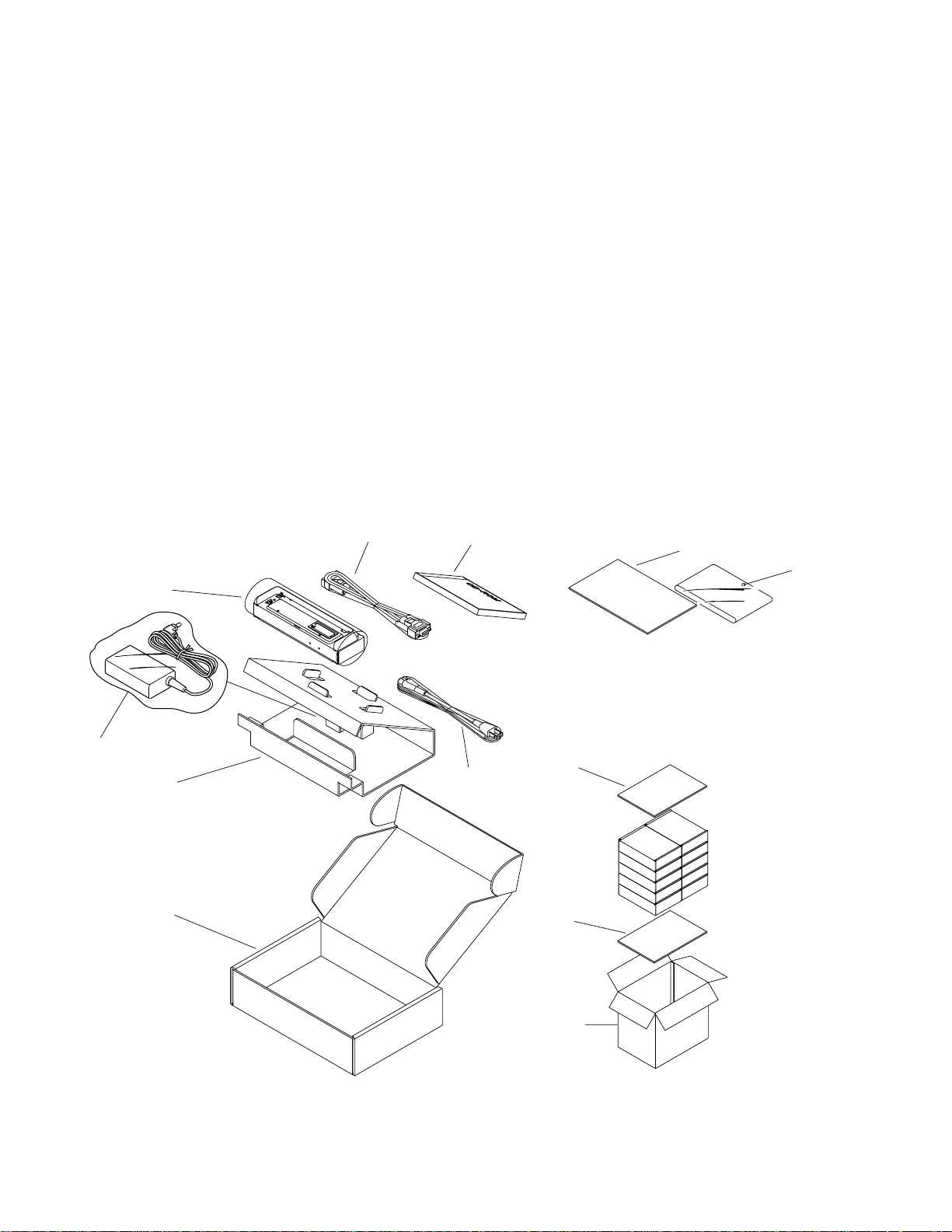
2. EXPLODED VIEWS AND PARTS LIST
2.1 PACKING
2
7
8
3
5
9
9
4
6
11
10
1
1. SAFETY INFORMATION
This service manual is intended for qualified service technicians; it is not meant for the casual do-it-yourselfer.
Qualified technicians have the necessary test equipment and tools, and have been trained to properly and safely repair
complex products such as those covered by this manual.
Improperly performed repairs can adversely affect the safety and reliability of the product and may void the warranty.
If you are not qualified to perform the repair of this product properly and safely, you should not risk trying to do so
and refer the repair to a qualified service technician.
Page 3
CD-PC1
3
1-1 Owner’s Manual CZR3221
1-2 Owner’s Manual CZR3222
1-3 Owner’s Manual CZR3227
* 1-4 Caution Card CZR3232
* 1-5 Label CZR3235
2 Polyethylene Bag CZE3171
3 Carton CZH6211
4 Contain Box CZH6212
> 5 AC Cord ADG7003
6 RS232C Cable(Straight) CZD6031
> 7 AC Adapter CZE3271
8 Board CZH6203
* 9 Board CZH6206
10 Spacer CZH6213
11 CD-ROM CZR3229
Mark No. Description Part No. Mark No. Description Part No.
- PACKING SECTION PARTS LIST
NOTE:
- Parts marked by “*” are generally unavailable because they are not in our Master Spare Parts List.
- Screws adjacent to ∇ mark on the product are used for disassembly.
- The > mark found on some component parts indicates the importance of the safety factor of the part. Therefore,
when replacing, be sure to use parts of identical designation.
- Owner's Manual
Model Part No. Language
CD-PC1/ES CZR3221 English
CZR3222 Spanish
CZR3227 Portuguese(B)
Page 4
4
CD-PC1
10
2
10
10
10
2
2
2
2
2
21
21
12
19
19
16
22
23
18
17
24
15
20
14
7
6
9
11
3
4
5
7
6
9
13
1
8
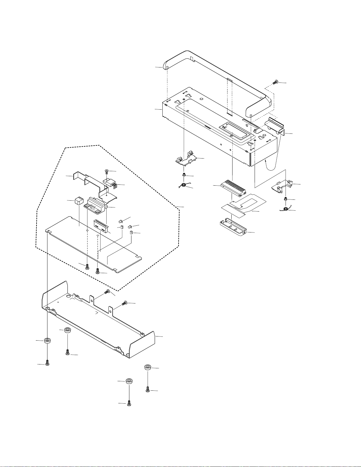
2.2 EXTERIOR
Page 5

CD-PC1
1 Screw BPZ26P080FZK
2 Screw BSZ26P060FZK
3 Connector(CN3) CKS4436
4 PCB CNP6124
5 Cover CNV6573
6 Screw CZB2041
7 Spring CZB2042
8 Holder CZN7682
9 Hook CZN7685
10 Foot CZN7686
11 Case CZN7688
12 Chassis CZN7689
13 Stopper CZN7691
14 PCB Unit CZW6032
15 Screw BSZ26P080FMC
16 Connector(CN4) CKS1568
17 Jack(CN2) CKS2577
18 Connector(CN1) CZD6033
19 LED Spacer CZE3277
20 Bracket CZN7687
21 Screw PMZ30P080FMC
22 LED(D3) SLR-332DU
23 LED(D5) SLR-332MG
24 IC(IC2) NJM78M05FA
- EXTERIOR SECTION PARTS LIST
Mark No. Description Part No.
Mark No. Description Part No.
5
Page 6

6
CD-PC1
1
23
4
1
234
D
C
B
A
1
2
3
4
5
6
8
9
7
C5+
11
12
13
14
15
CN1
9.8V
9.2V
5V
5
D6
HZS18(2)
HZS18(2)
D8
D9
D7
HZS18(2)
HZS18(2)
C6 1/50
C7 1/50
16
17
18
20
RIN2
RIN1
DOUT2
DOUT1
VCHA
STBY
VSS
C4C4+
VCC
3
ROUT2
ROUT1
DIN2
DIN1
C5-
C1C1+
VDD
GND
19
10
9
8
6
7
4
5
2
1
IC1
UPD4721GS
R13
1K
C8
1/50
C9
1/50
C
D5 SLR-332MG
C1 100/16 R9 820
2SC3928A
R6
10K
Q2
Q4
2SC3928A
Q3
2SB1132
R8
10K
R7 47K
Q1
DTC114EK
D4 HZS11(B2)
R5 18K
R4 10K
R3 100
D3 SLR-332DU
D2 ERA15-02
D1 ERA15-02
D17 ERA15-02
CN2
AC ADAPTER 9.8V,2A
RS-232C LINE DRIVER/RECEIVER
R1 2K
R10 2K
PCB UNIT
A
RS-232C
3. SCHEMATIC DIAGRAM
3.1 PCB UNIT
Note: When ordering service parts, be sure to refer to “EXPLODED VIEWS AND PARTS LIST” or “ELECTRICAL PARTS
LIST”.
A
Page 7

7
CD-PC1
5
6
78
5
6
78
D
C
B
A
5V
3V
5V
Q5
2SD1664
HZS7(C1)
HZS7(C1)
HZS7(C1)
D11
HZS7(C1)
D12
D13HZS7(C1)D14
D15HZS7(C1)D16
HZS4LL(A)
C11
D10
47/10
100
R14C10 R47
CN4
16
15
14
13
12
11
10
16
15
14
13
12
11
10
16
15
14
13
12
11
10
9
8
7
6
5
9
8
7
6
5
4
3
1
2
4
3
1
2
9
8
7
6
5
4
3
1
2
CN3
DETACH
DSENS
OEL+B
OELGND
KYDT
DPDT
ROTA
ROTB
VDD3V
NC.
NC.
SWDVDD
VDD
ILM+B
ILMGND
RST
DGND
IC2
NJM78M05FA
IN
GND
OUT
R12 47K
C5 R47
C4 10/16
C3 R47
C2 100/16
R10 2K
A
Page 8

PCB UNIT
4. PCB CONNECTION DIAGRAM
4.1 PCB UNIT
8
CD-PC1
1
23
4
1
234
D
C
B
A
SIDE A
A
A
Capacitor
Connector
P.C.Board
Chip Part
SIDE A
SIDE B
NOTE FOR PCB DIAGRAMS
1. The parts mounted on this PCB
include all necessary parts for
several destination.
For further information for
respective destinations, be sure
to check with the schematic dia-
gram.
2. Viewpoint of PCB diagrams
D17
R1
R3
J2
D15
D16
D12
D14
1
CN4
D11D3D13
D4
D1
D2
D7
D9
D8
D6
CN1
C1
C2
IC2
C11
D10
AC ADAPTER
CN2
RS-232C
C4
D5
R10
J1
C7C6C9C8
Page 9

9
CD-PC1
1
2
34
1
2
34
D
C
B
A
A
(1/2)
D17
R1
R3
R7
R9
R8
Q3
D15
J2
D1
D2
R4
Q1
R5
D4
D7
541
9876
D9
D8
D16
D6
C1
C2
C3
R6
Q2Q4
R12
C5
C4
C11
D10
C10
R10
R14
R13
C7
C6
C9C8
OUT
GND
IN
D12
D3
2
1591315
6101416
D14D13
D11
Q5
IC1
11
20
10
1
J1
D5
SIDE B
PCB UNIT
A
Page 10

10
CD-PC1
5. ELECTRICAL PARTS LIST
NOTE:
- Parts whose parts numbers are omitted are subject to being not supplied.
- The part numbers shown below indicate chip components.
Chip Resistor
RS1/_S___J,RS1/__S___J
Chip Capacitor (except for CQS.....)
CKS....., CCS....., CSZS.....
Unit Number : CZW6032
Unit Name : PCB Unit
MISCELLANEOUS
IC 1 IC UPD4721GS
IC 2 IC NJM78M05FA
Q 1 Transistor DTC114EK
Q 2 Transistor 2SC3928A
Q 3 Transistor 2SB1132
Q 4 Transistor 2SC3928A
Q 5 Transistor 2SD1664
D 1 Diode ERA15-02
D 2 Diode ERA15-02
D 3 LED SLR-332DU
D 4 Diode HZS11(B2)
D 5 LED SLR-332MG
D 6 Diode HZS18(2)
D 7 Diode HZS18(2)
D 8 Diode HZS18(2)
D 9 Diode HZS18(2)
D 10 Diode HZS4LL(A)
D 11 Diode HZS7(C1)
D 12 Diode HZS7(C1)
D 13 Diode HZS7(C1)
D 14 Diode HZS7(C1)
D 15 Diode HZS7(C1)
D 16 Diode HZS7(C1)
D 17 Diode ERA15-02
RESISTORS
R 1 RD1/4PU202J
R 3 RD1/4PU101J
R 4 RS1/16S103J
R 5 RS1/16S183J
R 6 RS1/16S103J
R 7 RS1/16S473J
R 8 RS1/16S103J
R 9 RS1/16S821J
R 10 RD1/4PU202J
R 12 RS1/16S473J
R 13 RS1/16S102J
R 14 RS1/16S101J
CAPACITORS
C 1 CEAT101M16
C 2 CEAT101M16
C 3 CKSRYF474Z16
C 4 CEAT100M16
C 5 CKSRYF474Z16
C 6 CEAT1R0M50
C 7 CEAT1R0M50
C 8 CEAT1R0M50
C 9 CEAT1R0M50
C 10 CKSRYF474Z16
C 11 CEAT470M10
=====Circuit Symbol and No.===Part Name Part No.
--- ------ ------------------------------------------ -------------------------
=====Circuit Symbol and No.===Part Name Part No.
--- ------ ------------------------------------------ -------------------------
A
Page 11

11
CD-PC1
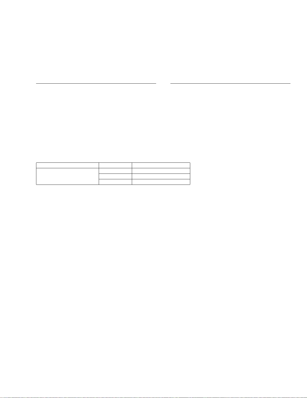
6. ADJUSTMENT
7. GENERAL INFORMATION
There is no information to be shown in this chapter.
Front panel
connector
Front panel
Examples)
DEH-P9350/ES
OS: English Windows 98, English Windows 98SE,
English Windows 2000, or English Windows Me
Connection: Serial port capable of connecting
RS-232C D-Sub 9-pin connector
- Connection Diagram
Page 12

12
CD-PC1
8. OPERATIONS AND SPECIFICATIONS
8.1 OPERATIONS
Mounting the Front Panel
Mount the front panel to this unit.
Align with the mounting guide and mount the front panel.
Align the position of the unit and front panel connectors and push the front panel straight
down until a click is heard and the panel is securely locked. If the front panel is correctly
mounted, the Ready indicator will light.
Note:
• For front panels with a cut-off corner, the direction of the mounting guide needs to be changed.
In this case, pull off the mounting guide and remount as shown in the illustration below.
Checking the front panel Mounting the mounting guide
Removing the Front Panel
Slide off the front panel to remove.
Caution:
• When mounting the front panel by sliding, damage may occur to the front panel connector of
the unit. Always mount the front panel by pushing straight down.
Mounting guide
Ready indicator
Power indicator
Page 13

13
CD-PC1
8.2 SPECIFICATIONS
Main unit
Type: PC link kit
Power supply: DC 10 V
Demand power
(when front panel is connected): 3 W
Demand power
(when front panel is not connected): 1 W
Weight: 0.30 kg
Dimensions (excl. protrusions):
190 (W) × 43 (H) × 59 (D) mm
AC adapter
Power supply: AC 100 V – 240 V, 50/60 Hz
Rating: 45 – 57 VA
Rated output: DC 10 V
Demand power: 0.6 W
Weight: 0.15 kg
Dimensions: 98 (W) × 26 (H) × 54 (D) mm
 Loading...