

Pioneer CDJ-200 Service manual
PIONEER CORPORATION 4-1, Meguro 1-chome, Meguro-ku, Tokyo 153-8654, Japan
PIONEER ELECTRONICS (USA) INC. P.O. Box 1760, Long Beach, CA 90801-1760, U.S.A.
PIONEER EUROPE NV Haven 1087, Keetberglaan 1, 9120 Melsele, Belgium
PIONEER ELECTRONICS ASIACENTRE PTE. LTD. 253 Alexandra Road, #04-01, Singapore 159936
PIONEER CORPORATION 2005
NECESSARY INFORMATION FOR DHHS RULES
MARKED ON THE TOP COVER BELOW:
CAUTION – LASER RADIATION WHEN OPEN.
DO NOT STARE INTO BEAM
ORDER NO.
RRV3095
CDJ-200
COMPACT DISC PLAYER
CDJ-200
THIS MANUAL IS APPLICABLE TO THE FOLLOWING MODEL(S) AND TYPE(S).
Model Type Power Requirement Remarks
CDJ-200 KUCXJ AC120V
CDJ-200 RLTXJ AC110-120V/AC220-240V
CDJ-200 WYXJ AC220-240V
CDJ-200 RFXJ AC110-120V/AC220-240V
For details, refer to "Important Check Points for good servicing".
T-IZY MAR. 2005 printed in Japan

1234
SAFETY INFORMATION
A
This service manual is intended for qualified service technicians ; it is not meant for the casual do-ityourselfer. Qualified technicians have the necessary test equipment and tools, and have been trained
to properly and safely repair complex products such as those covered by this manual.
Improperly performed repairs can adversely affect the safety and reliability of the product and may
void the warranty. If you are not qualified to perform the repair of this product properly and safely, you
should not risk trying to do so and refer the repair to a qualified service technician.
WARNING
This product contains lead in solder and certain electrical parts contain chemicals which are known to the state of California to
cause cancer, birth defects or other reproductive harm.
B
NOTICE
(FOR CANADIAN MODEL ONLY)
Fuse symbols (fast operating fuse) and/or (slow operating fuse) on PCB indicate that replacement parts must
be of identical designation.
REMARQUE
(POUR MODÈLE CANADIEN SEULEMENT)
Les symboles de fusible (fusible de type rapide) et/ou (fusible de type lent) sur CCI indiquent que les pièces
de remplacement doivent avoir la même désignation.
Health & Safety Code Section 25249.6 - Proposition 65
C
(FOR USA MODEL ONLY)
1. SAFETY PRECAUTIONS
The following check should be performed for the
continued protection of the customer and service
technician.
ANY MEASUREMENTS NOT WITHIN THE LIMITS
OUTLINED ABOVE ARE INDICATIVE OF A POTENTIAL
SHOCK HAZARD AND MUST BE CORRECTED BEFORE
RETURNING THE APPLIANCE TO THE CUSTOMER.
LEAKAGE CURRENT CHECK
Measure leakage current to a known earth ground
(water pipe, conduit, etc.) by connecting a leakage
current tester such as Simpson Model 229-2 or
D
E
equivalent between the earth ground and all exposed
metal parts of the appliance (input/output terminals,
screwheads, metal overlays, control shaft, etc.). Plug
the AC line cord of the appliance directly into a 120V
AC 60 Hz outlet and turn the AC power switch on. Any
current measured must not exceed 0.5 mA.
Reading should
not be above
0.5 mA
Earth
ground
Device
under
test
Also test with
plug reversed
(Using AC adapter
plug as required)
Leakage
current
tester
Test all
exposed metal
surfaces
2. PRODUCT SAFETY NOTICE
Many electrical and mechanical parts in the appliance
have special safety related characteristics. These are
often not evident from visual inspection nor the protection
afforded by them necessarily can be obtained by using
replacement components rated for voltage, wattage, etc.
Replacement parts which have these special safety
characteristics are identified in this Service Manual.
Electrical components having such features are
identified by marking with a > on the schematics and on
the parts list in this Service Manual.
The use of a substitute replacement component which
does not have the same safety characteristics as the
PIONEER recommended replacement one, shown in the
parts list in this Service Manual, may create shock, fire,
or other hazards.
Product Safety is continuously under review and new
instructions are issued from time to time. For the latest
information, always consult the current PIONEER Service
Manual. A subscription to, or additional copies of,
PIONEER Service Manual may be obtained at a nominal
charge from PIONEER.
AC Leakage Test
F
2
1234
CDJ-200

5678
IMPORTANT
THIS PIONEER APPARATUS CONTAINS
LASER OF CLASS 1.
SERVICING OPERATION OF THE APPARATUS
SHOULD BE DONE BY A SPECIALLY
INSTRUCTED PERSON.
WARNING !
THE AEL (ACCESSIBLE EMISSION LEVEL) OF THE LASER POWER OUTPUT IS LESS THAN CLASS 1
BUT THE LASER COMPONENT IS CAPABLE OF EMITTING RADIATION EXCEEDING THE LIMIT FOR
CLASS 1.
A SPECIALLY INSTRUCTED PERSON SHOULD DO SERVICING OPERATION OF THE APPARATUS.
LASER DIODE CHARACTERISTICS
MAXIMUM OUTPUT POWER : 5 mW
WAVELENGTH : 780 – 785 nm
LABEL CHECK (for RLTXJ, WYXJ and RFXJ types)
for WYXJ for WYXJ for RLTXJ
for RFXJ
A
B
C
(Printed on the chassis)
Additional Laser Caution
1. Laser Interlock Mechanism
The position of the switch (S1901) for detecting loading
completion is detected by the system microprocessor, and the
design prevents laser diode oscillation when the switch is not
in LPS1 terminal side (when the mechanism is not clamped
and LPS1 signal is high level.)
Thus, the interlock will no longer function if the switch is
deliberately set to LPS1 terminal side. ( if LPS1 signal is low
level ).
In the test mode∗ the interlock mechanism will not function.
Laser diode oscillation will continue, if pin 41 of TC94A15FG
(IC105) on the MAIN Assy is connected to GND, or else the
terminals of Q105 are shorted to each other (fault condition).
2. When the cover is opened, close viewing of the objective
lens with the naked eye will cause exposure to a Class 1
laser beam.
∗ : See page 51.
D
E
F
56
CDJ-200
3
7
8
1234
[Important Check Points for Good Servicing]
In this manual, procedures that must be performed during repairs are marked with the below symbol.
Please be sure to confirm and follow these procedures.
A
1. Product safety
Please conform to product regulations (such as safety and radiation regulations), and maintain a safe servicing environment by
following the safety instructions described in this manual.
1 Use specified parts for repair.
Use genuine parts. Be sure to use important parts for safety.
2 Do not perform modifications without proper instructions.
Please follow the specified safety methods when modification(addition/change of parts) is required due to interferences such as
radio/TV interference and foreign noise.
B
C
D
3 Make sure the soldering of repaired locations is properly performed.
When you solder while repairing, please be sure that there are no cold solder and other debris.
Soldering should be finished with the proper quantity. (Refer to the example)
4 Make sure the screws are tightly fastened.
Please be sure that all screws are fastened, and that there are no loose screws.
5 Make sure each connectors are correctly inserted.
Please be sure that all connectors are inserted, and that there are no imperfect insertion.
6 Make sure the wiring cables are set to their original state.
Please replace the wiring and cables to the original state after repairs.
In addition, be sure that there are no pinched wires, etc.
7 Make sure screws and soldering scraps do not remain inside the product.
Please check that neither solder debris nor screws remain inside the product.
8 There should be no semi-broken wires, scratches, melting, etc. on the coating of the power cord.
Damaged power cords may lead to fire accidents, so please be sure that there are no damages.
If you find a damaged power cord, please exchange it with a suitable one.
9 There should be no spark traces or similar marks on the power plug.
When spark traces or similar marks are found on the power supply plug, please check the connection and advise on secure
connections and suitable usage. Please exchange the power cord if necessary.
0 Safe environment should be secured during servicing.
When you perform repairs, please pay attention to static electricity, furniture, household articles, etc. in order to prevent injuries.
Please pay attention to your surroundings and repair safely.
2. Adjustments
To keep the original performance of the products, optimum adjustments and confirmation of characteristics within specification.
Adjustments should be performed in accordance with the procedures/instructions described in this manual.
3. Lubricants, Glues, and Replacement parts
Use grease and adhesives that are equal to the specified substance.
E
Make sure the proper amount is applied.
4. Cleaning
For parts that require cleaning, such as optical pickups, tape deck heads, lenses and mirrors used in projection monitors, proper
cleaning should be performed to restore their performances.
5. Shipping mode and Shipping screws
To protect products from damages or failures during transit, the shipping mode should be set or the shipping screws should be
installed before shipment. Please be sure to follow this method especially if it is specified in this manual.
F
4
1234
CDJ-200

5678
CONTENTS
1. SPECIFICATIONS.............................................................................................................................................6
2. EXPLODED VIEWS AND PARTS LIST.............................................................................................................8
2.1 PACKING SECTION ...................................................................................................................................8
2.2 EXTERIOR SECTION ..............................................................................................................................10
2.3 CONTROL PANEL SECTION...................................................................................................................12
2.4 SLOT-IN MECHANISM SECTION ............................................................................................................14
3. BLOCK DIAGRAM AND SCHEMATIC DIAGRAM ..........................................................................................16
3.1 BLOCK DIAGRAM....................................................................................................................................16
3.2 OVERALL WIRING DIAGRAM .................................................................................................................18
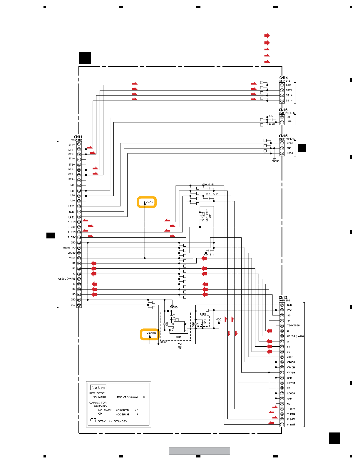
3.3 MAIN ASSY (1/2)......................................................................................................................................20
3.4 MAIN ASSY (2/2)......................................................................................................................................22
3.5 RLYB ASSY ..............................................................................................................................................23
3.6 DISP, KSWB, INDB, SLDB, JLED and JOGB ASSYS..............................................................................24
3.7 JACK ASSY..............................................................................................................................................26
3.8 ACIN, TRNS, SLMB, SECB and REGB ASSYS.......................................................................................28
3.9 VOLTAGES................................................................................................................................................30
3.10 WAVEFORMS.........................................................................................................................................32
4. PCB CONNECTION DIAGRAM ......................................................................................................................34
4.1 JACK ASSY..............................................................................................................................................35
4.2 MAIN and RLYB ASSYS...........................................................................................................................36
4.3 DISP, KSWB, INDB, SLDB, JLED and JOGB ASSYS..............................................................................38
4.4 ACIN, TRNS, SLMB, SECB and REGB ASSYS.......................................................................................42
5. PCB PARTS LIST............................................................................................................................................46
6. ADJUSTMENT ................................................................................................................................................50
7. GENERAL INFORMATION .............................................................................................................................51
7.1 DIAGNOSIS..............................................................................................................................................51
7.1.1 SERVICE MODE................................................................................................................................51
7.1.2 POWER ON SEQUENCE ..................................................................................................................58
7.1.3 DISASSEMBLY ..................................................................................................................................59
7.2 PARTS ......................................................................................................................................................64
7.2.1 IC........................................................................................................................................................64
7.2.2 FL .......................................................................................................................................................76
8. PANEL FACILITIES .........................................................................................................................................77
A
B
C
D
E
F
56
CDJ-200
5
7
8

1234
1. SPECIFICATIONS
• KUCXJ type
1. General
A
System..............................Compact disc digital audio system
Power requirements.....................................AC 120 V, 60 Hz
Power consumption.......................................................14 W
Operating temperature............+5˚C – +35˚C (+41˚F – +95˚F)
Operating humidity...............................................5 % – 85 %
(There should be no condensation of moisture.)
Weight..............................................................3.2 kg (7.1 lb)
Dimensions.........................216 (W) × 292 (D) × 99.5 (H) mm
8 – 1/2 (W) × 11 –1/2 (D) × 3 – 15/16 (H) in
2. Audio section
B
Frequency response........................................4 Hz – 20 kHz
Signal-to-noise ratio..........................110 dB or more (JEITA)
Distortion.................................................... .0.006 % (JEITA)
3. Accessories
• Operating instructions........................................................1
• Power cord........................................................................1
• Audio cable....................................................................... 1
• Control cable..................................................................... 1
• Forced eject pin (housed in a groove in the bottom panel)... 1
• Limited warranty................................................................1
C
NOTE:
Specifications and design are subject to possible modification
with-out notice.
• WYXJ type
1. General
System.......................... Compact disc digital audio system
Power requirements .................... AC 220-240 V, 50/60 Hz
Power consumption ..................................................... 16 W
Operating temperature .................................. +5°C – +35°C
D
Operating humidity ............................................ 5 % – 85 %
(There should be no condensation of moisture.)
Weight ....................................................................... 3.2 kg
Dimensions ..................... 216 (W) x 292 (D) x 99.5 (H) mm
• RLTXJ, RFXJ types
1. General
System........................... Compact disc digital audio system
Power requirements .... AC 110-120 V/220-240 V, 50/60 Hz
Power consumption ..................................................... 16 W
For Taiwan: 17 W
Operating temperature .................................. +5°C – +35°C
Operating humidity ........................................... 5 % – 85 %
(There should be no condensation of moisture.)
Weight ........................................................................3.2 kg
Dimensions ...................... 216 (W) x 292 (D) x 99.5 (H) m
m
2. Audio section
Frequency response...................................... 4 Hz – 20 kHz
Signal-to-noise ratio ....................... 110 dB or more (JEITA)
Distortion ................................................... 0.006 % (JEITA)
3. Accessories
• Operating instructions ..................................................... 1
• Power cord ...................................................................... 1
• Audio cable ..................................................................... 1
• Control cable ................................................................... 1
• Forced eject pin (housed in a groove in the bottom panel)... 1
NOTE:
Specifications and design are subject to possible modification
with-out notice.
Voltage selector (RLTXJ, RFXJ types only)
• You can find the voltage selector switch on the bottom plate
of the unit.
The factory setting for the voltage selector is 220 – 240 V.
Please set it to the correct voltage for your country or region.
• For Taiwan, please set to 110 – 120 V before using.
Before changing the voltage, disconnect the AC power cord.
Use a medium size screwdriver to change the voltage
selector switch.
220-240V
2. Audio section
Frequency response...................................... 4 Hz – 20 kHz
Signal-to-noise ratio ....................... 110 dB or more (JEITA)
Distortion ................................................... 0.006 % (JEITA)
3. Accessories
E
• Operating instructions ..................................................... 1
• Power cord ...................................................................... 1
• Audio cable ..................................................................... 1
• Control cable ................................................................... 1
• Forced eject pin (housed in a groove in the bottom panel)... 1
NOTE:
Specifications and design are subject to possible modification
with-out notice.
F
6
1234
110-120V
CDJ-200

5678
Accessories
Power cord
(KUCXJ : ADG7021)
(RLTXJ : ADG1154)
(WYXJ : ADG1154)
(RFXJ : ADG7097)
Audio cable
(VDE1064 or XDE3045)
L= 1.5m
Control cable
(ADE7108 or XDE3063)
L= 1 m
Forced eject pin
(housed in a groove
in the bottom panel)
(DEX1008)
A
B
C
D
E
56
CDJ-200
F
7
7
8
1234
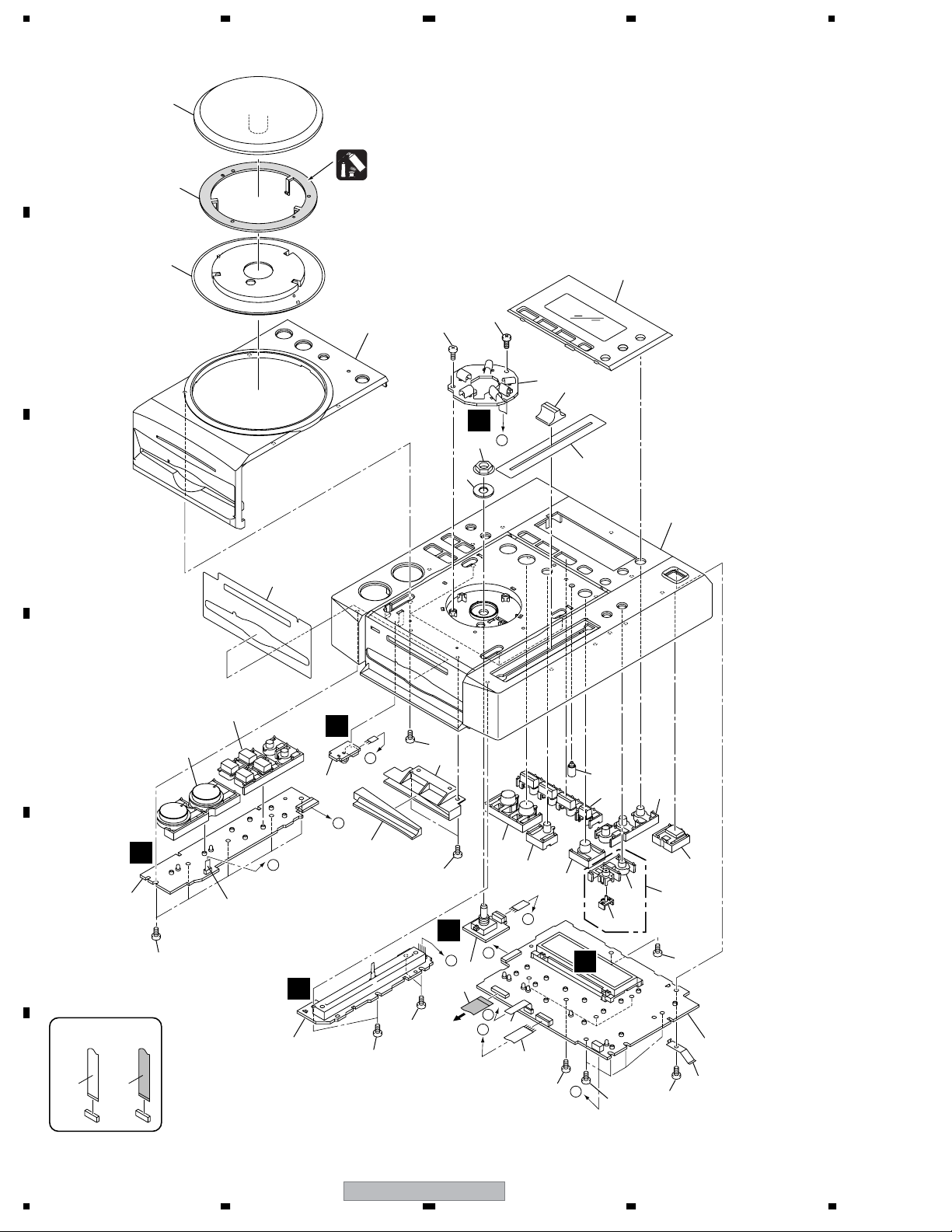
2. EXPLODED VIEWS AND PARTS LIST
NOTES:
A
Parts marked by "NSP" are generally unavailable because they are not in our Master Spare Parts List.
The mark found on some component parts indicates the importance of the safety factor of the part.
Therefore, when replacing, be sure to use parts of identical designation.
Screws adjacent to mark on product are used for disassembly.
For the applying amount of lubricants or glue, follow the instructions in this manual.
(In the case of no amount instructions, apply as you think it appropriate.)
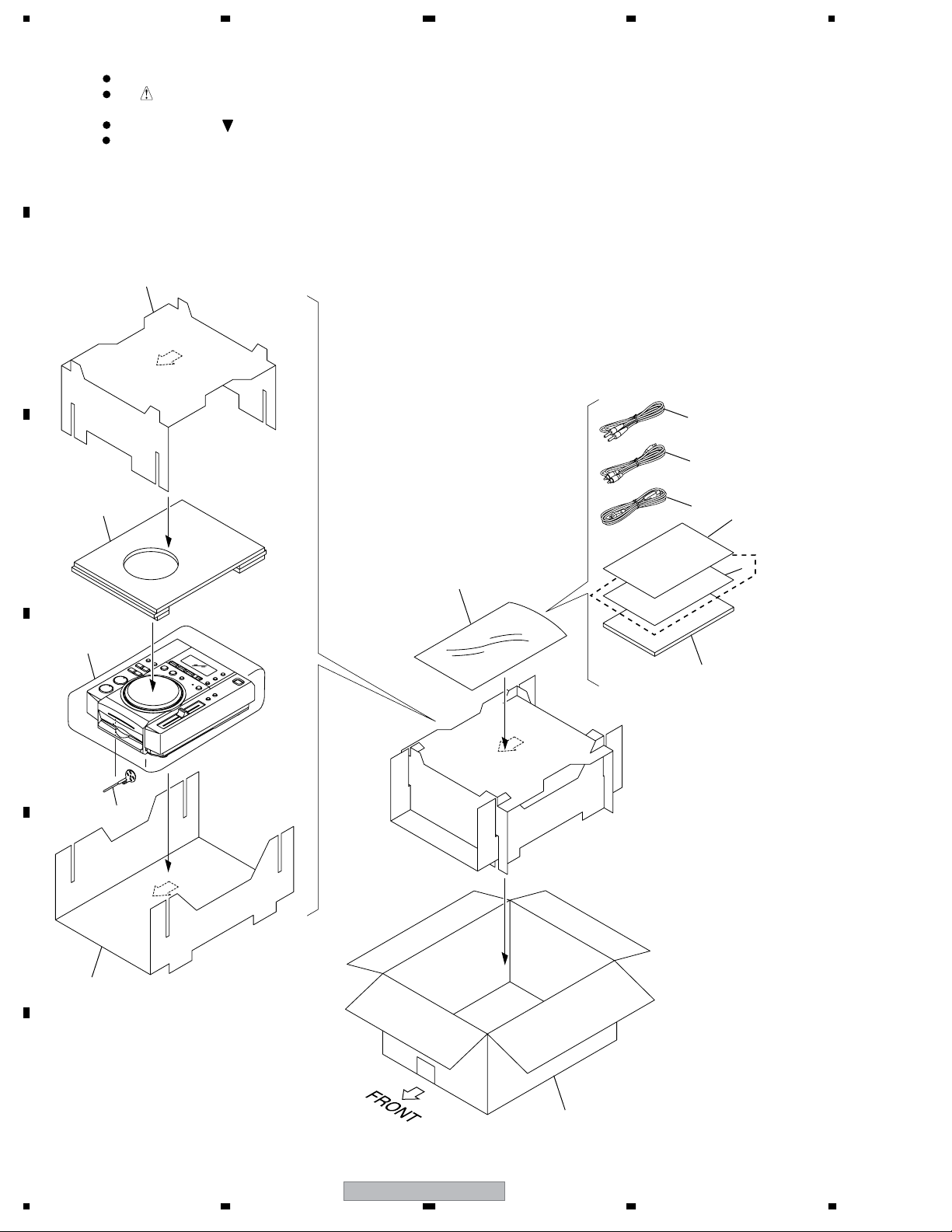
2.1 PACKING SECTION
10
B
C
12
3
2
1
7
KUCXJ
6
8
9
5
D
4
E
11
Only
F
8
1234
CDJ-200
13

>
5678
(1) PACKING SECTION PARTS LIST
No. Description Part No.
Mark
1Power Cord See Contrast table (2)
2Audio Cable
3 Control Cable
4Forced Eject Pin DEX1008
5 Operating Instructions See Contrast table (2)
NSP 6 Limited Warranty See Contrast table (2)
NSP 7 User Seat DRM1262
NSP 8 Polyethylene Bag AHG7117
(0.06 x 230 x 340)
9Packing Sheet AHG7015
VDE1064 or XDE3045
ADE7108 or XDE3063
A
10 Pad A DHA1638
11 Pad B DHA1639
12 Pad C DHA1640
13 Packing Case See Contrast table (2)
(2) CONTRAST TABLE
CDJ-200/KUCXJ, RLTXJ, WYXJ and RFXJ are constructed the same except for the following:
Mark No. Symbol and Description
>
NSP 6 Limited Warranty ARY7043 Not used Not used Not used
1Power Cord ADG7021 ADG1154 ADG1154 ADG7097
5 Operating Instructions DRB1377 DRB1378 DRB1376 DRB1378
13 Packing Case DHG2495 DHG2496 DHG2494 DHG2500
CDJ-200/
KUCXJ
CDJ-200/
RLTXJ
CDJ-200/
WYXJ
CDJ-200/
RFXJ
B
C
D
56
CDJ-200
E
F
9
7
8

1234
2.2 EXTERIOR SECTION
23
A
K
18
40
43
40
Refer to
"2.3 CONTROL PANEL SECTION".
A
J
1
B
41
C
D
29
B
27
A
27
29
22
25
21
41
32
C
40
40
31
28
L
I
L
41
33
40
15
F
41
K
39
H
41
G
5
38
F
4
6
J
16
K
20
9
17
41
G
34
WYXJ Only
10
J
N
41
40
L
D
B
27
E
29
24
41
E
D
41
41
M
36
35
RLTXJ, RFXJ Only
32
I
14
8
41
37
41
I
H
M
M
3
11
41
42
E
Refer to
"2.4 SLOT-IN MECHANISM SECTION".
F
NON-CONTACT
SIDE
CONTACT SIDE
13
10
1234
29
27
30
41
A
41
7
12
C
41
19
26
2
B
19
CDJ-200
>
>
5678
(1) EXTERIOR SECTION PARTS LIST
No. Description Part No.
Mark
1 MAIN Assy DWG1587
2RLYB Assy DWX2429
3JACK Assy DWX2433
4ACIN Assy See Contrast table (2)
5 TRNS Assy See Contrast table (2)
6 SLMB Assy DWS1355
7 SECB Assy DWR1394
8 REGB Assy DWR1393
9 Fuse (FU11) See Contrast table (2)
10 Power Transformer (T22) See Contrast table (2)
11 24P Flexible Cable DDD1275
12 32P Flexible Cable DDD1276
13 24P Flexible Cable DDD1278
14 9P Flexible Cable DDD1279
15 Earth Lead Unit/300V DDF1032
16 Connector Assy PF03PP-B17
17 Power Button DAC2254
NSP 18 Silicone Sheet D5 L DEB1456
19 Insulator DEC2250
20 Protector DEC2808
21 PU Caution DEC2856
22 PCB Stay DNH2640
No. Description Part No.
Mark
23 Heatsink DNH2641
24 Trans. Plate DNH2670
25 Card Spacer DNK2769
NSP 26 Chassis See Contrast table (2)
27 Damper CNV6011
28 Earth Spring DBH1398
29 Float Spring G5 DBH1494
30 FPC Guard DBK1282
31 Mecha Plate DNH2642
32 Nyron Rivet (3 x 4.5) RBM-003
33 Cord Clamper RNH-184
34 Caution Label HE See Contrast table (2)
35 Caution Label See Contrast table (2)
36 Caution Label See Contrast table (2)
37 Nut M12 DBN1012
38 DM Screw DBA1260
39 Screw BBZ40P060FTC
40 Screw BBZ30P060FTC
41 Screw BPZ30P080FTC
42 Jumper Wire 6P(J904) D20PDY0610E
43 15P Flexible Cable DDD1277
A
B
C
(2) CONTRAST TABLE
CDJ-200/KUCXJ, RLTXJ, WYXJ and RFXJ are constructed the same except for the following:
Mark No. Symbol and Description
4ACIN Assy DWR1388 DWR1389 DWR1387 DWR1389
5 TRNS Assy DWR1391 DWR1392 DWR1391 DWR1392
>
>
>
NSP 26 Chassis DNK4423 DNK4424 DNK4386 DNK4427
9 Fuse (FU11 : 2.0A/125V) REK1111 Not used Not used
9 Fuse (FU11 : T1AL250V) Not used REK1022 REK1022
10 Power Transformer (T22) DTT1172 DTT1171 DTT1171
34 Caution Label HE Not used Not used PRW1233 Not used
35 Caution Label Not used Not used VRW1094 Not used
36 Caution Label Not used PRW1018 Not used DRW2248
CDJ-200/
KUCXJ
CDJ-200/
RLTXJ
CDJ-200/
WYXJ
CDJ-200/
RFXJ
Not used
REK1022
DTT1171
D
E
F
56
CDJ-200
11
7
8
1234
2.3 CONTROL PANEL SECTION
23
21
22
Dyefree
GEM1036
(ZLX-ME413A)
20
34
34
27
5
28
A
B
G
D
33
35
C
16
19
D
E
F
D
2
NON-CONTACT
SIDE
CONTACT SIDE
34
18
9
E
34
34
25
34
H
To MAIN
CN105
26
15
10
11
12
C
B
E
6
7
C
37
D
38
34
C
E
31
34
30
13
14
29
34
1
17
34
8
A
36
A
3
B
24
F
4
34
12
CDJ-200
1234

5678
CONTROL PANEL SECTION PARTS LIST
No. Description Part No.
Mark
1 DISP Assy DWG1588
2 KSWB Assy DWS1356
3 INDB Assy DWX2438
4 SLDB Assy DWX2430
5 JLED Assy DWX2432
6 JOGB Assy DWX2431
7 15P Flexible Cable DDD1277
8 PLAY Button DAC2244
9 SEARCH Button DAC2245
10 LOOP Button DAC2246
A
11 RELOOP Button DAC2270
12 BEAT LOOP Button DAC2271
13 TIME Button DAC2249
14 EJECT Button DAC2253
15 JET Button DAC2266
16 Slide Sheet (GRAY) DAH2374
17 Earth Plate DBK1224
18 Vessel Sheet DEC2751
19 Control Panel A DNK4384
20 Control Panel B DNK4385
21 Jog Dial DNK4387
22 POM Ring DNK4388
23 Jog Lens DNK4389
24 Front Lens DNK4390
25 Reflector DNK4391
26 BEAT Lens DNK4392
27 Display Panel DNK4492
28 Slide Knob (SILVER) DNK4448
29 TEMPO Button Assy DXA2014
30 TEMPO Button DAC2258
31 TEMPO Lens DNK4421
32 • • • • •
33 Nut M9 DBN1008
34 Screw BPZ30P080FTC
35 JOG Washer DBF1002
B
C
D
36 Jumper Wire 3P D20PDY0305E
37 Jumper Wire 4P D20PDY0405E
38 Jumper Wire 6P D20PDY0610E
56
CDJ-200
E
F
13
7
8
1234
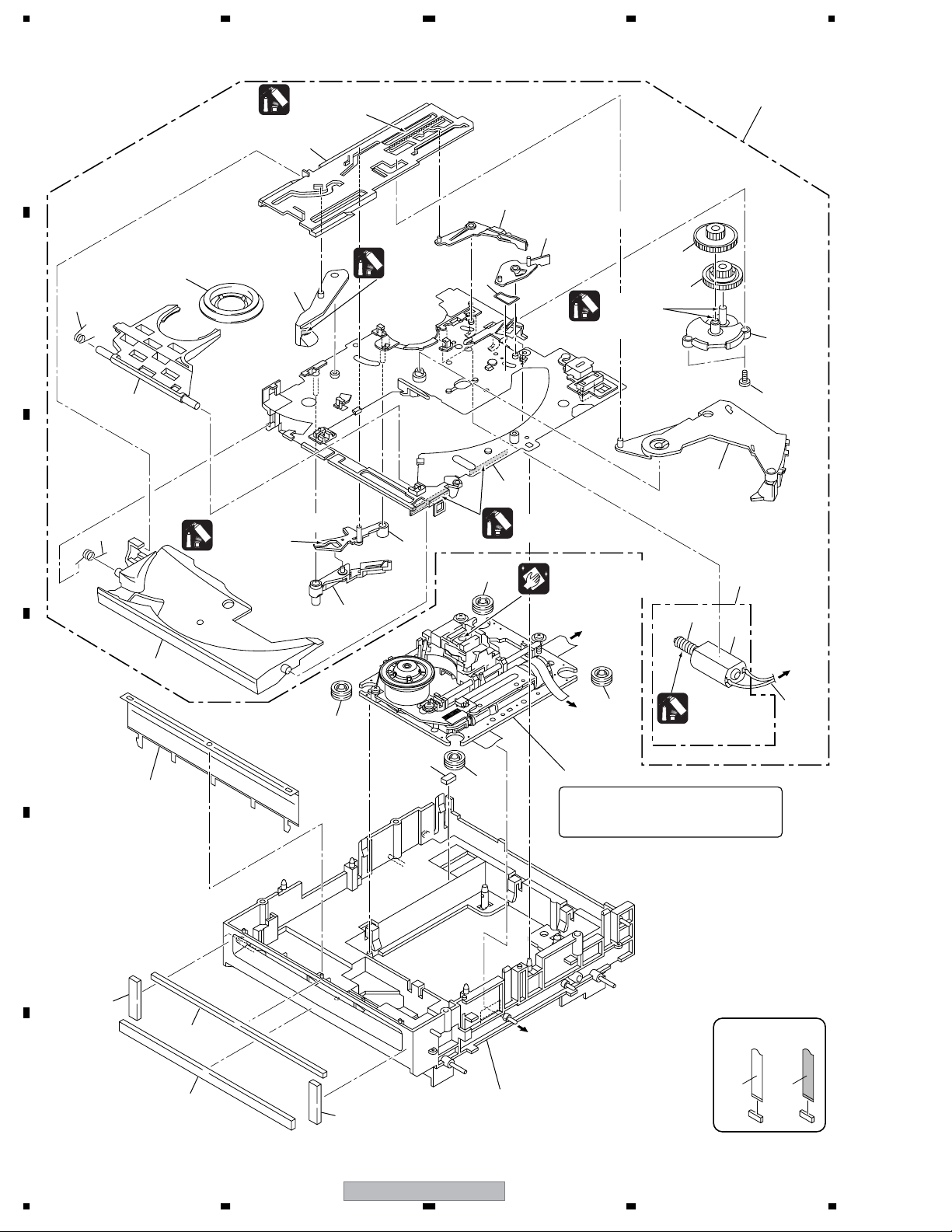
2.4 SLOT-IN MECHANISM SECTION
Grease
A
GYA1001
(ZLB-PN397B)
1
11
20
21
Dyefree
23
B
7
10
GEM1036
(ZLX-ME413A)
9
Grease
GYA1001
(ZLB-PN397B)
13
19
C
8
Dyefree
GEM1036
15
(ZLX-ME413A)
16
Dyefree
GEM1036 (ZLX-ME413A)
25
Cleaning liquid : GEM1004
Cleaning paper : GED-008
RLYB CN12
To
(Pickup)
12
18
17
22
24
14
3
4
5
To
RLYB CN16
(Loading Motor)
25
D
25
To
RLYB CN14
(Stepping Motor)
Grease
GYA1001
(ZLB-PN397B)
6
27
31
25
2
Note:
The TM. Assy 03-S is supplied only in
assembly form, not as a single part.
E
30
29
F
28
30
26
To MAIN CN102
(Spindle Motor)
NON-CONTACT
SIDE
CONTACT SIDE
14
CDJ-200
1234

5678
SLOT-IN MECHANISM SECTION PARTS LIST
Mark No. Description Part No.
NSP 1 Slot-in Mecha SV Assy DXA2005
2 TM. Assy 03-S VXX2909
3 DC Motor Assy-S DXX2510
NSP 4 Worm Gear DNK3910
NSP 5 DC Motor S (ROHS) DXM1230
6 Connector Assy PF02PY-B22
7 Clamp Spring DBH1374
8 Guide Spring DBH1375
9 SW Lever Spacer SV DEC2831
10 Loading Lever DNK3406
A
11 Main Cam DNK3407
12 Disc Guide DNK3478
13 Clamp Arm DNK3576
14 Eject Lever DNK3684
15 Lever AP DNK3835
16 Lever BP DNK3836
17 Loading Gear DNK3911
18 Drive Gear DNK3912
19 Loading Base SV DNK4369
20 SW Lever SV1 DNK4370
21 SW Lever SV2 DNK4371
22 Gear Holder SV DNK4372
23 Clamper 04 Assy DXB1859
24 Screw BPZ20P060FTC
25 Floating Rubber (SI) VEB1351
26 Float Base 04 Assy DXB1838
27 Spacer POR (T3) DEB1566
28 Vessel Cushion A DEC2852
29 Vessel Cushion B DEC2853
30 Vessel Cushion C DEC2854
31 Front Sheet DED1132
B
C
D
56
CDJ-200
E
F
15
7
8
1234
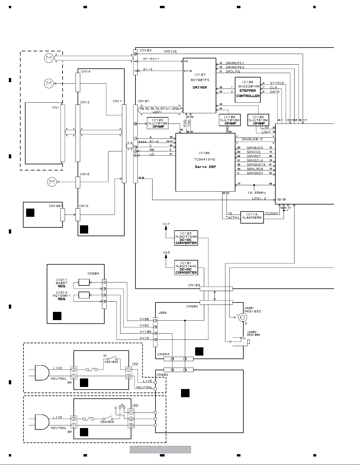
3. BLOCK DIAGRAM AND SCHEMATIC DIAGRAM
3.1 BLOCK DIAGRAM
A
TM. ASSY 03-S (VXX2909)
SPINDLE
MOTOR 04
STEPPING
MOTOR 04
B
PICKUP ASSY
C
D
E
DC MOTOR
ASSY-S
(DXX2510)
L
SLMB ASSY
N
For KUCXJ, WYXJ
RLYB ASSY
B
REGB ASSY
SECB ASSY
M
COMPARATOR
DIGITAL OUT
CONTROL
ACIN ASSY
J
For RLTXJ, RFXJ
F
ACIN ASSY
J
16
1234
S2
S1
BROWN
VIOLET
BLUE
J2
J3
CDJ-200
TRNS ASSY
K
5678
A
MAIN ASSY
A
B
D
KSWB ASSY
JACK ASSY
I
E
INDB ASSY
PHONES
C
AUDIO OUT
D
E
H
JOGB ASSY
SLDB ASSY
F
DISP ASSY
C
G
JLED ASSY
56
CDJ-200
F
17
7
8
1234
3.2 OVERALL WIRING DIAGRAM
A
SPINDLE MOTOR 04
STEPPING
MOTOR 04
B
TM. ASSY 03-S (VXX2909)
SLOT-IN MECHA SV ASSY (DXA2005)
C
1
2
3
4
5
6
7
8
9
10
11
12
(S)
(S)
(S)
(S)
(F)
(F)
(T)
(T)
B
RLYB ASSY
(DWX2429)
(RF)
(T)
(T)
(RF)
(RF)
(RF)
D
FOR
KUCXJ, WYXJ
E
FOR
RLTXJ, RFXJ
(RF)
(T)
F
(F)
(T)
(S)
18
PICKUP ASSY
DC MOTOR
ASSY-S
(DXX2510)
SLMB ASSY
L
(DWS1355)
POWER CORD
KUCXJ : ADG7021
WYXJ : ADG1154
POWER CORD
RLTXJ : ADG1154
RFXJ : ADG7097
J
KUCXJ : XKP3042
WYXJ : XKP3041
ACIN ASSY
(RLTXJ, RFXJ : DWR1389)
: RF DATA SIGNAL ROUTE
: TRACKING DATA SIGNAL ROUTE
: FOCUS SERVO LOOP LINE
: TRACKING SERVO LOOP LINE
: STEPPING SERVO LOOP LINE
1234
ACIN ASSY
(KUCXJ : DWR1388)
(WYXJ : DWR1387)
J
REGB ASSY
CDJ-200
(DWR1393)
N
K
TRNS ASSY
(KUCXJ, WYXJ : DWR1391)
(RLTXJ, RFXJ : DWR1392)
SECB ASSY
M
(DWR1394)
5678
A
D
KSWB ASSY
(DWS1356)
E
INDB ASSY
(DWX2438)
JLED ASSY
(DWX2432)
B
G
A
A 1/2, A 2/2
MAIN ASSY (DWG1587)
C
DISP ASSY
(DWG1588)
SLDB ASSY
F
(DWX2430)
JACK ASSY
(DWX2433)
C
JOGB ASSY
(DWX2431)
H
D
L
AUDIO OUT
I
R
E
PHONES
÷
When ordering service parts, be sure to refer to "EXPLODED VIEWS and PARTS
LIST" or "PCB PARTS LIST".
÷
The > mark found on some component parts indicates the importance of the safety
factor of the part. Therefore, when replacing, be sure to use parts of identical
designation.
÷
56
: The power supply is shown with the marked box.
CDJ-200
F
19
7
8
1234
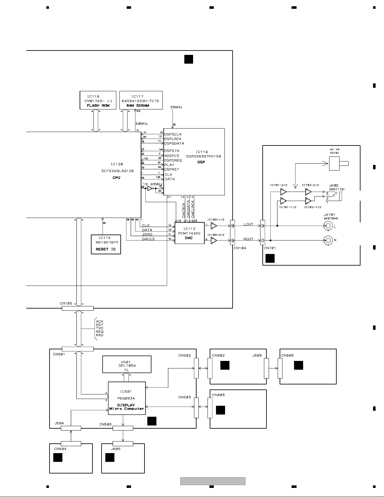
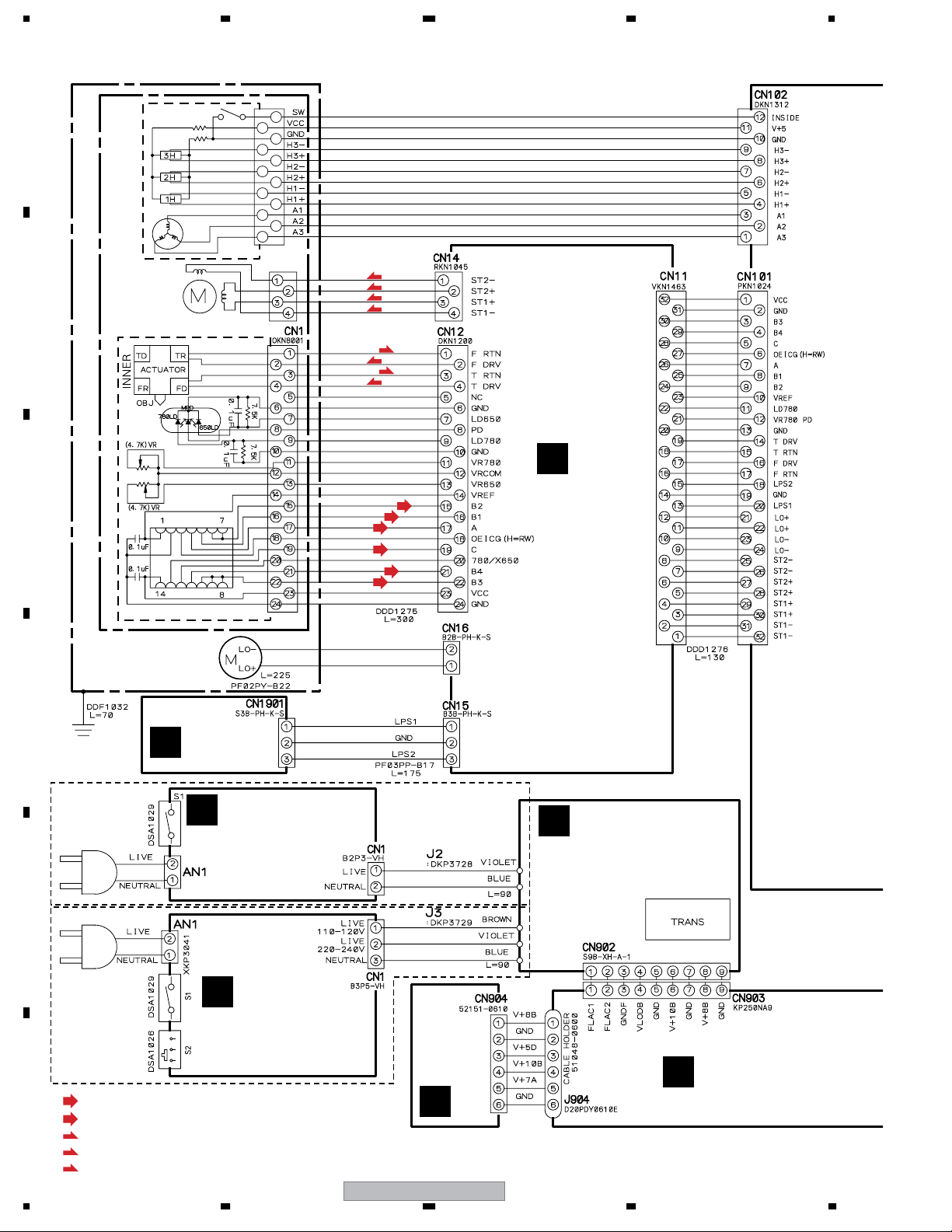
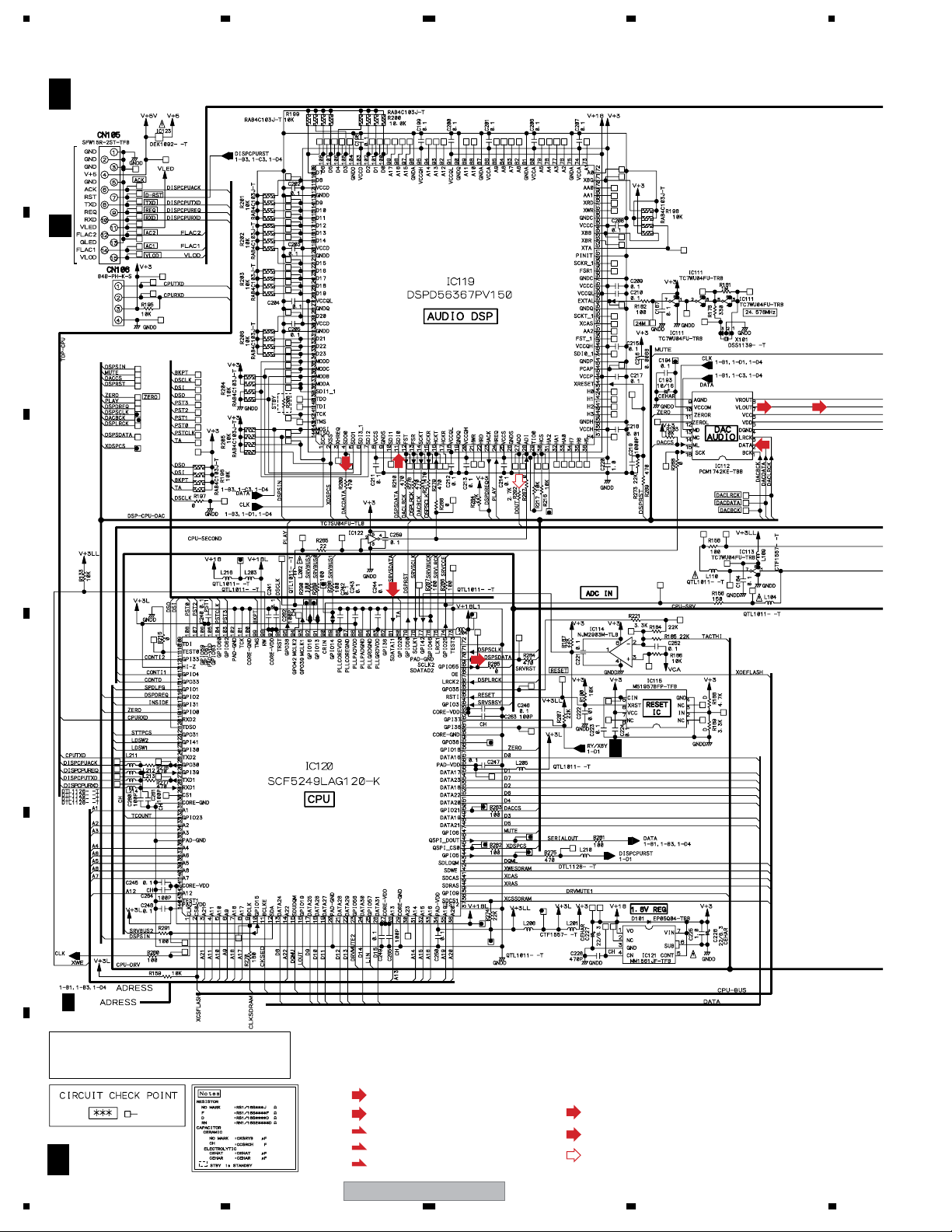
3.3 MAIN ASSY (1/2)
A
B
C
A 1/2
CN501
C
UPDATE
CONNECTOR
MAIN ASSY (DWG1587)
(D)
(D)
(D)
(D)
(D)
D
2/2A
E
2/2A
CAUTION : FOR CONTINUED PROTECTION AGAINST
RISK OF FIRE. REPLACE ONLY WITH
SAME TYPE NO. DEK1092- 466.200
F
MFD, BY LITTELFUSE INK. FOR IC123.
A 1/2
20
1234
(RF)
: RF DATA SIGNAL ROUTE
(T)
: TRACKING DATA SIGNAL ROUTE
(F)
: FOCUS SERVO LOOP LINE
(T)
: TRACKING SERVO LOOP LINE
(S)
: STEPPING SERVO LOOP LINE
CDJ-200
(D)
: AUDIO DATA SIGNAL ROUTE
: AUDIO SIGNAL ROUTE (L ch)
: AUDIO SIGNAL ROUTE (Digital)
5678
13
10
I
CN701
M
CN905
A
B
(T)
(RF)
(T)
(RF)
9
7
1
(RF)
(RF)
12
8
2
(S)
(S)
(S)
(S)
6
5
C
3
4
(F)
(F)
(T)
(T)
15 16
(T)
(RF)
(RF)
(RF)
(T)
(RF)
B
D
CN11
E
14
(D)
(T)
(F)
(F)
(S)
(S)
(S)
(S)
(T)
(S)
(S)
(S)
(S)
11
(F)
(F)
(T)
(T)
To
SPINDLE
MOTOR
04
F
56
CDJ-200
A 1/2
21
7
8

1234
3.4 MAIN ASSY (2/2)
A
B
C
A 2/2
MAIN ASSY (DWG1587)
2/2A
2/2
A
D
E
F
22
A 2/2
CDJ-200
1234
5678
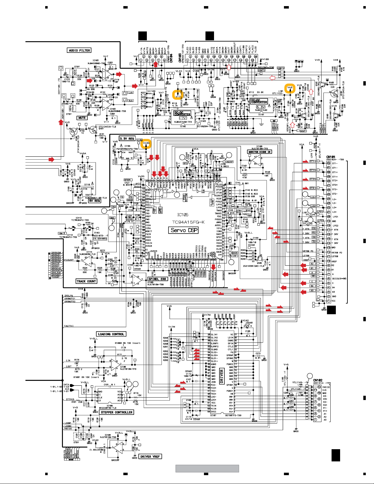
3.5 RLYB ASSY
RLYB ASSY (DWX2429)
B
(RF)
: RF DATA SIGNAL ROUTE
(T)
: TRACKING DATA SIGNAL ROUTE
(F)
: FOCUS SERVO LOOP LINE
(T)
: TRACKING SERVO LOOP LINE
(S)
: STEPPING SERVO LOOP LINE
A
CN101
A 1/2
(S)
(S)
(S)
(S)
(S)
(S)
(S)
(S)
To
STEPPING
MOTOR 04
To
DC MOTOR
B
ASSY-S
(S)
(S)
(S)
(S)
L
CN1901
C
(F)
(F)
(T)
(T)
(F)
(F)
(T)
(T)
(RF)
(RF)
(T)
(T)
(RF)
(RF)
(RF)
(RF)
(T)
(RF)
(RF)
D
(T)
(F)
(T)
(T)
(F)
(T)
(T)
(RF)
(RF)
E
To
PICKUP
ASSY
CN1
(T)
(T)
(F)
(F)
F
56
CDJ-200
B
23
7
8
1234
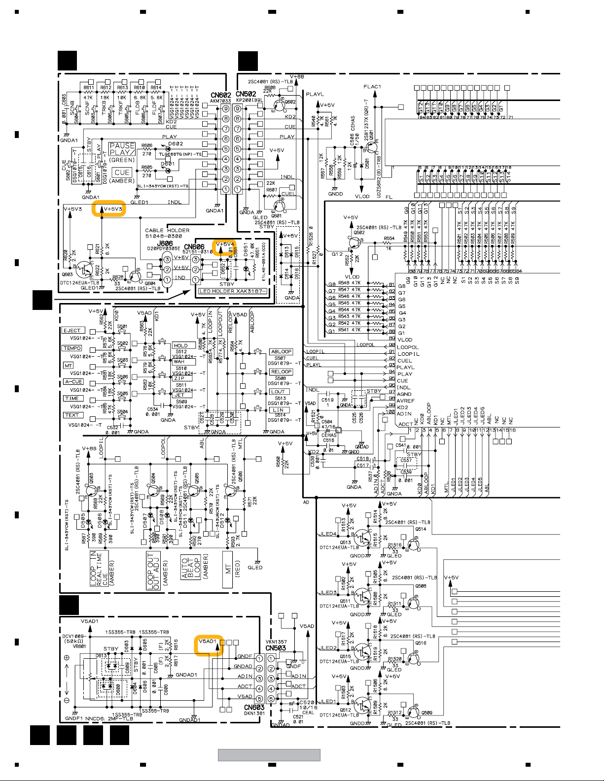
3.6 DISP, KSWB, INDB, SLDB, JLED and JOGB ASSYS
KSWB ASSY (DWS1356)
A
B
D
INDB ASSY (DWX2438)
DISP ASSY (DWG1588)
C
E
C
D
E
SLDB ASSY (DWX2430)
F
F
C D E F
24
1234
CDJ-200
 Loading...