

Pioneer A-30-K, A-30-S User Manual

Operating Instructions | Mode d’emploi | Bedienungsanleitung |
Istruzioni per I’uso | Handleiding | Manual de instrucciones |
Инструкции по эксплуатации
ME06
A-
30
-K/-S
Integrated Amplifier | Amplificateur Intégré |
Eingebauter Verstärker | Amplificatore Integrato |
Geïntegreerde versterker | Amplificador integrado |
A-
20
10
A-
-K/-S
-K/-S
IMPORTANT
CAUTION
RISK OF ELECTRIC SHOCK
DO NOT OPEN
The lightning flash with arrowhead symbol,
within an equilateral triangle, is intended to
alert the user to the presence of uninsulated
“dangerous voltage” within the product’s
enclosure that may be of sufficient
magnitude to constitute a risk of electric
shock to persons.
CAUTION:
TO PREVENT THE RISK OF ELECTRIC
SHOCK, DO NOT REMOVE COVER (OR
BACK). NO USER-SERVICEABLE PARTS
INSIDE. REFER SERVICING TO QUALIFIED
SERVICE PERSONNEL.
European model only
Information for users on collection and disposal of old equipment and used batteries
Symbol for
equipment
Symbol examples
for batteries
Pb
These symbols on the products, packaging, and/or accompanying documents mean
that used electrical and electronic products and batteries should not be mixed with
general household waste.
For proper treatment, recovery and recycling of old products and used batteries,
please take them to applicable collection points in accordance with your national
legislation.
By disposing of these products and batteries correctly, you will help to save valuable
resources and prevent any potential negative effects on human health and the
environment which could otherwise arise from inappropriate waste handling.
For more information about collection and recycling of old products and batteries,
please contact your local municipality, your waste disposal service or the point of sale
where you purchased the items.
These symbols are only valid in the European Union.
For countries outside the European Union:
If you wish to discard these items, please contact your local authorities or dealer and
ask for the correct method of disposal.
The exclamation point within an equilateral
triangle is intended to alert the user to the
presence of important operating and
maintenance (servicing) instructions in the
literature accompanying the appliance.
D3-4-2-1-1_A1_En
K058a_A1_En
WARNING
This equipment is not waterproof. To prevent a fire or
shock hazard, do not place any container filled with
liquid near this equipment (such as a vase or flower
pot) or expose it to dripping, splashing, rain or
moisture.
D3-4-2-1-3_A1_En
WARNING
Before plugging in for the first time, read the following
section carefully.
The voltage of the available power supply differs
according to country or region. Be sure that the
power supply voltage of the area where this unit
will be used meets the required voltage (e.g., 230 V
or 120 V) written on the rear panel.
D3-4-2-1-4*_A1_En
WARNING
To prevent a fire hazard, do not place any naked flame
sources (such as a lighted candle) on the equipment.
D3-4-2-1-7a_A1_En
VENTILATION CAUTION
When installing this unit, make sure to leave space
around the unit for ventilation to improve heat radiation
(at least 30 cm at top, 10 cm at rear, and 10 cm at each
side).
WARNING
Slots and openings in the cabinet are provided for
ventilation to ensure reliable operation of the product,
and to protect it from overheating. To prevent fire
hazard, the openings should never be blocked or
covered with items (such as newspapers, table-cloths,
curtains) or by operating the equipment on thick carpet
or a bed.
D3-4-2-1-7b*_A1_En
Operating Environment
Operating environment temperature and humidity:
+5 °C to +35 °C (+41 °F to +95 °F); less than 85 %RH
(cooling vents not blocked)
Do not install this unit in a poorly ventilated area, or in
locations exposed to high humidity or direct sunlight (or
strong artificial light)
If the AC plug of this unit does not match the AC
outlet you want to use, the plug must be removed
and appropriate one fitted. Replacement and
mounting of an AC plug on the power supply cord of
this unit should be performed only by qualified
service personnel. If connected to an AC outlet, the
cut-off plug can cause severe electrical shock. Make
sure it is properly disposed of after removal.
The equipment should be disconnected by removing
the mains plug from the wall socket when left unused
for a long period of time (for example, when on
vacation).
CAUTION
The /I STANDBY/ON switch on this unit will not
completely shut off all power from the AC outlet.
Since the power cord serves as the main disconnect
device for the unit, you will need to unplug it from the
AC outlet to shut down all power. Therefore, make
sure the unit has been installed so that the power
cord can be easily unplugged from the AC outlet in
case of an accident. To avoid fire hazard, the power
cord should also be unplugged from the AC outlet
when left unused for a long period of time (for
example, when on vacation).
D3-4-2-1-7c*_A1_En
D3-4-2-2-1a_A1_En
D3-4-2-2-2a*_A1_En
This product is for general household purposes. Any
failure due to use for other than household purposes
(such as long-term use for business purposes in a
restaurant or use in a car or ship) and which requires
repair will be charged for even during the warranty
period.
K041_A1_En
POWER-CORD CAUTION
Handle the power cord by the plug. Do not pull out the
plug by tugging the cord and never touch the power
cord when your hands are wet as this could cause a
short circuit or electric shock. Do not place the unit, a
piece of furniture, etc., on the power cord, or pinch the
cord. Never make a knot in the cord or tie it with other
cords. The power cords should be routed such that they
are not likely to be stepped on. A damaged power cord
can cause a fire or give you an electrical shock. Check
the power cord once in a while. When you find it
damaged, ask your nearest PIONEER authorized
service center or your dealer for a replacement.
S002*_A1_En
(A-30 only)
CAUTION:
HOT SURFACE. DO NOT TOUCH.
The top surface over the internal
heatsink may become hot when
operating this product continuously.
Thank you for buying this Pioneer
product.
Please read through these operating instructions so that
you will know how to operate your model properly. After
you have finished reading the instructions, put them in a
safe place for future reference.
Contents
01 Before you start
What’s in the box. . . . . . . . . . . . . . . . . . . . . . . . . . 4
Loading the batteries in the remote control
(Except A-10) . . . . . . . . . . . . . . . . . . . . . . . . . . . . .4
Using the remote control . . . . . . . . . . . . . . . . . . . . .4
Installing the amplifier. . . . . . . . . . . . . . . . . . . . . . 4
02 Connecting up
Making cable connections. . . . . . . . . . . . . . . . . . .5
About “Bi-wiring” . . . . . . . . . . . . . . . . . . . . . . . . . . 5
Connecting speaker cables . . . . . . . . . . . . . . . . . . 6
Connecting audio cables . . . . . . . . . . . . . . . . . . . . 6
Using centralized control with other Pioneer
components (Except A-10) . . . . . . . . . . . . . . . . . . . 6
Plugging in . . . . . . . . . . . . . . . . . . . . . . . . . . . . . . 6
03 Controls and displays
Front panel . . . . . . . . . . . . . . . . . . . . . . . . . . . . . . 7
Rear panel . . . . . . . . . . . . . . . . . . . . . . . . . . . . . . . 8
Remote control (Except A-10) . . . . . . . . . . . . . . . . 9
04 Operation
Playback . . . . . . . . . . . . . . . . . . . . . . . . . . . . . . . 10
Set the power to Standby. . . . . . . . . . . . . . . . . . . .10
When using the unit as a power amplifier
(A-30 only) . . . . . . . . . . . . . . . . . . . . . . . . . . . . . . .10
Making an audio recording . . . . . . . . . . . . . . . . .11
To set for automatic standby status
(Auto Power Down) . . . . . . . . . . . . . . . . . . . . . . . 11
Restoring all the settings to the factory default
settings . . . . . . . . . . . . . . . . . . . . . . . . . . . . . . . . 11
05 Additional information
Troubleshooting. . . . . . . . . . . . . . . . . . . . . . . . . . 12
Cleaning the unit . . . . . . . . . . . . . . . . . . . . . . . . . 12
Specifications . . . . . . . . . . . . . . . . . . . . . . . . . . . 13
3
01 Before you start
7 m
30 °
30 °
Chapter 1:
Before you start
What’s in the box
Please confirm that the following accessories are in the
box when you open it.
• Remote control (Except A-10)
• AAA/IEC R03 dry cell batteries x2 (Except A-10)
•Power cord
• Warranty card
• Operating instructions (This document)
Note
• Illustrations featured in the Operating Instructions
may have been modified or simplified for ease of
explanation, and may therefore differ from the
actual product appearance.
• The illustrations used here are mainly of the A-30.
Loading the batteries in the remote
control (Except A-10)
1 Open the rear lid.
A-20
4
En
A-30
2 Insert the new batteries, matching the
polarities as indicated inside the case.
A-30
A-20
3 Close the rear lid.
A-30
The batteries included with the unit have been provided
to allow you check product operation and may not last
long. We recommend using alkaline batteries that have
a longer life.
WARNING
• Do not use or store batteries in direct sunlight or
other excessively hot place, such as inside a car or
near a heater. This can cause batteries to leak,
overheat, explode or catch fire. It can also reduce
the life or performance of batteries.
Caution
Incorrect use of batteries may result in such hazards as
leakage and bursting. Observe the following
precautions:
• When inserting the batteries, make sure not to
damage the springs on the battery’s terminals.
A-20
• Do not use any batteries other than the ones
specified. Also, do not use a new battery together
with an old one.
• When loading the batteries into the remote control,
set them in the proper direction, as indicated by the
polarity marks ( and ).
• Do not heat batteries, disassemble them, or throw
them into flames or water.
• Batteries may have different voltages, even if they
are the same size and shape. Do not use different
types of batteries together.
• To prevent leakage of battery fluid, remove the
batteries if you do not plan to use the remote
control for a long period of time (1 month or more).
If the fluid should leak, wipe it carefully off the
inside of the case, then insert new batteries. If a
battery should leak and the fluid should get on your
skin, flush it off with large quantities of water.
• When disposing of used batteries, please comply
with governmental regulations or environmental
public institution’s rules that apply in your country/
area.
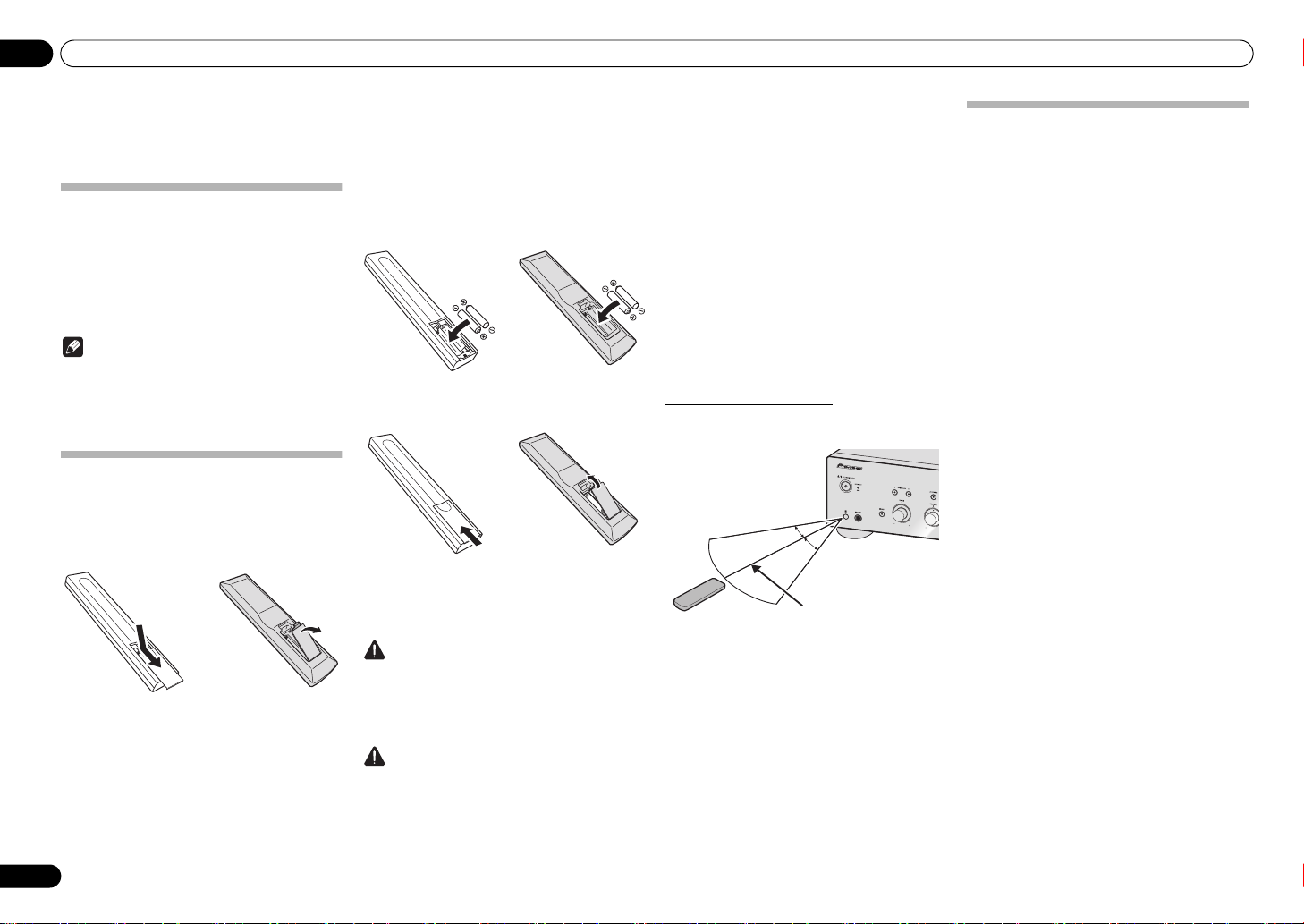
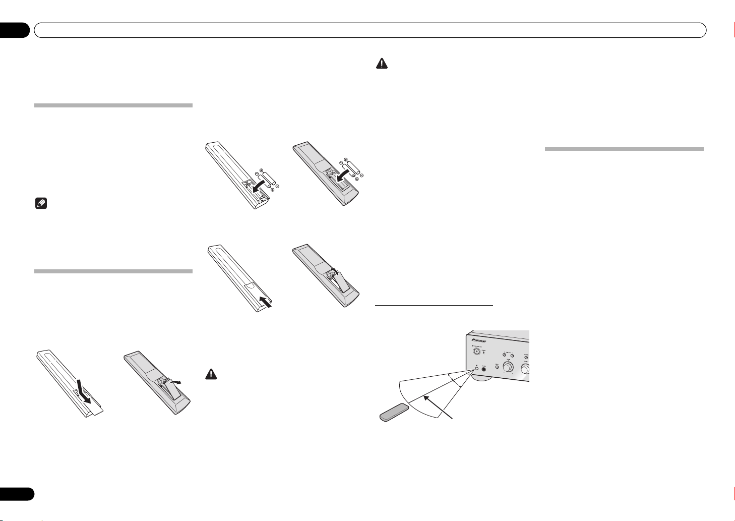
Using the remote control
The remote has a range of about 7 m at an angle of about
30º from the remote sensor.
Keep in mind the following when using the remote
control:
• Make sure that there are no obstacles between the
remote and the remote sensor on the unit.
• Remote operation may become unreliable if strong
sunlight or fluorescent light is shining on the unit’s
remote sensor.
• Remote controllers for different devices can
interfere with each other. Avoid using remotes for
other equipment located close to this unit.
• Replace the batteries when you notice a fall off in
the operating range of the remote.
Installing the amplifier
When installing this unit, make sure to put it on a level
and stable surface.
• Don’t install it on the following places:
– on a color TV (the screen may distort)
– near a cassette deck (or close to a device that
gives off a magnetic field). This may interfere with
the sound.
– in direct sunlight
– in damp or wet areas
– in extremely hot or cold areas
– in places where there is vibration or other
movement
– in places that are very dusty
– in places that have hot fumes or oils (such as a
kitchen)
• Do not mount the unit on a sofa or other object or
material with absorbent qualities, since sound
quality may be adversely affected.

Connecting up 02
REC
R
L
OUTPUT
R
L
PLAY
RL
AUDIO
OUTPUT
PRE OUT
R
L
LRLRL
R
L
R
LRL
R
L
R
L
R
L
R
L
R
LRL
R
L
R
L
R
L
R
MENU
iPod
Music>
Extras>
Settings>
Shuffle Songs
Backlight
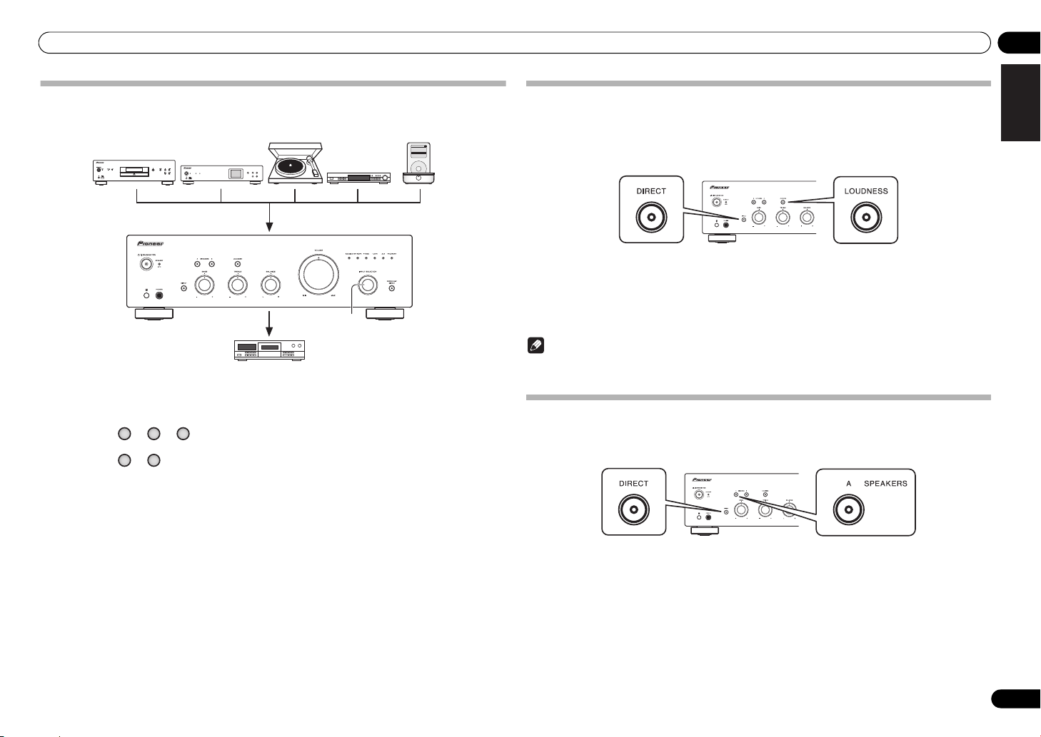
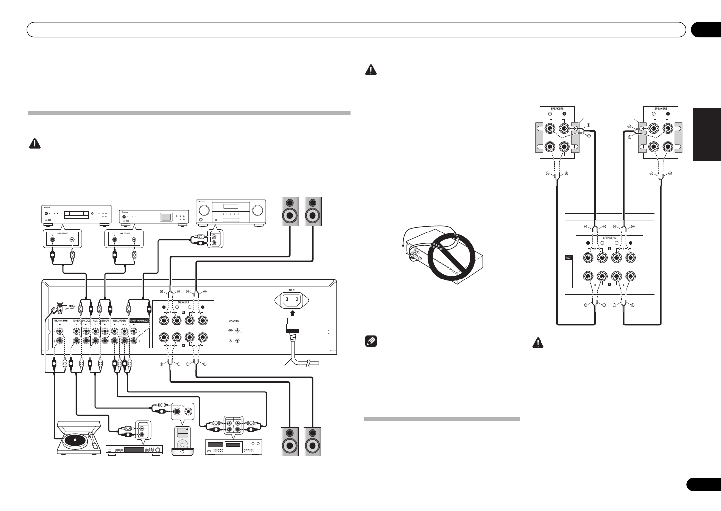
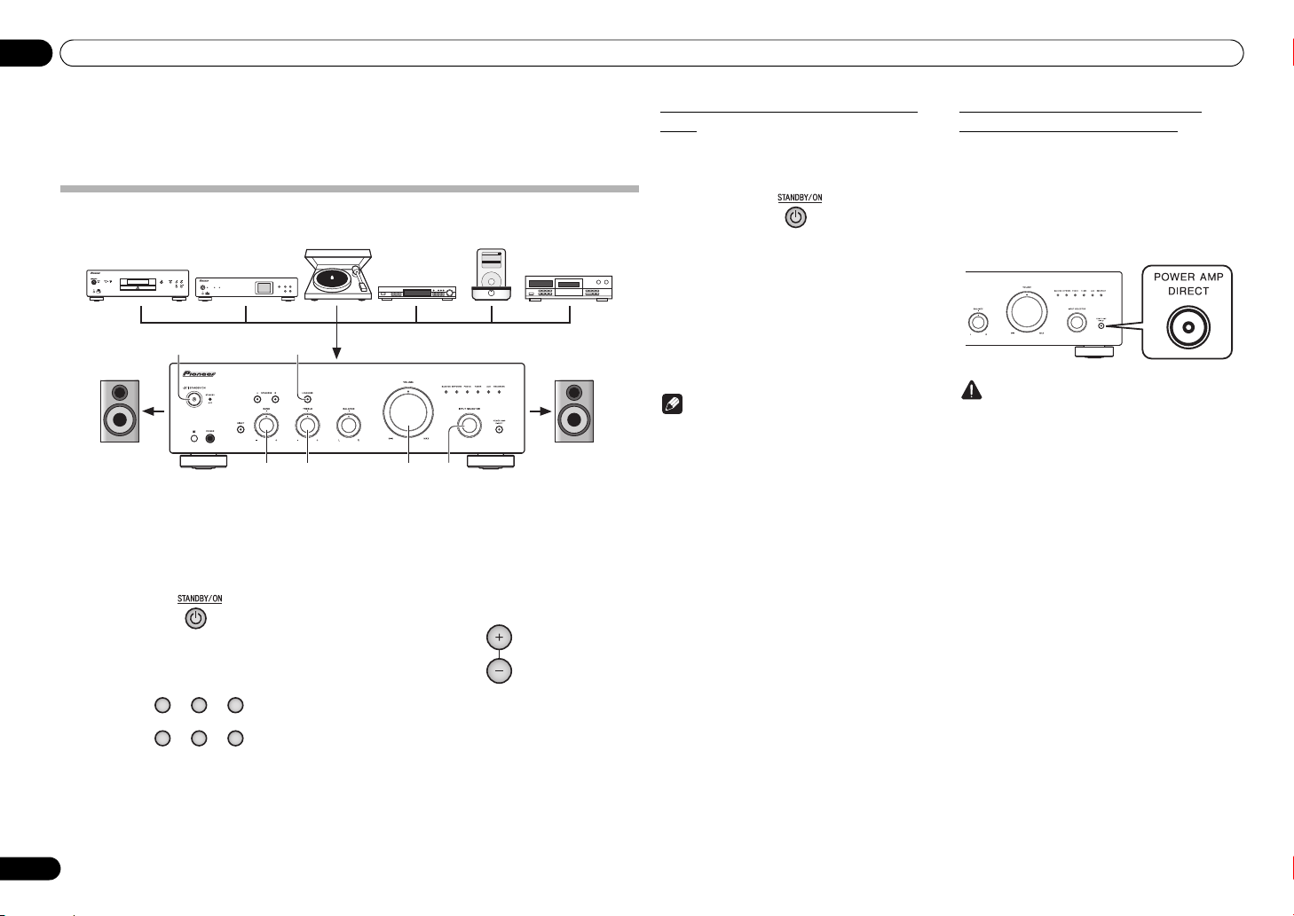
SACD/CD player
Network audio player
PRE OUT jacks on preamplifier or AV amplifier
Speaker system B
Speaker system A
Turntable
Tuner
iPod dock, etc
CD recorder or
tape deck
Right
Left
Right
Left
Power cord
(included)
A-30’s rear panel
A-30 only
HIGH
LOW
HIGH
LOW
Speaker system
Left
Speaker system
Right
A-30’s rear
panel
Remove the shorting
bar between the +
and – terminals.
Chapter 2:
Connecting up
Making cable connections
Caution
• Before making or changing the connections, switch off the power and disconnect the power cord from the AC
outlet.
• Connect the power cord after all the connections between devices have been completed.
Caution
•The SIGNAL GND terminal is provided to reduce
noise when connecting the unit to components
such as an analog turntable.
• Do not connect the PHONO (MM) terminals to any
component other than a turntable; also, do not
connect to a turntable equipped with built-in
equalizer. An excessively high sound output may be
produced, resulting in damage to your speakers or
other devices.
• The unit’s PHONO (MM) terminals are designed to
be used with turntables equipped with MM
(moving-magnet) type cartridges. Turntables
equipped with MC (moving-coil) cartridges cannot
be used.
• Make sure not to bend the cables over the top of
this unit (as shown in the illustration). If this
happens, the magnetic field produced by the
transformers in this unit may cause a humming
noise from the speakers.
• The unit’s POWER AMP DIRECT terminals should
never be connected to any other component’s
connectors except PRE-AMP OUT.
• If your turntable has a grounding wire, secure it to
the ground terminal on this amplifier.
Note
• When connecting a tape cassette deck, playback
noise may be heard, depending on the installation
location. This noise is caused by leakage flux from
the amplifier’s transformer. In this event, change
the installation location, or move the deck farther
from the amplifier.
• iPod is a trademark of Apple Inc., registered in the
U.S. and other countries.
About “Bi-wiring”
This unit can be used with speakers that support biwiring. Be sure to connect the high-frequency and
low-frequency connections correctly.
• During playback, be sure that both the SPEAKERS
A button and SPEAKERS B button are set to ON
(page 7).
Caution
• When using bi-wiring to connect speakers, avoid
adverse affects on the amplifier by being sure to
remove the HIGH and LOW short bars provided
with the speakers. For detailed information, consult
the instructions provided with the speakers.
• When using speakers with removable network
circuits, note that if the network is removed, no
effect will be produced and damage may be caused
to the speaker.
• Another method of connection is to connect the
SPEAKERS A terminals to HIGH and the
SPEAKERS B terminals to LOW (reverse that shown
in the illustration).
English
DeutschFrançais
Italiano Español Русский
Nederlands
5
En
02 Connecting up
10 mm
Cap
Left (white)
Right (red)
Other Pioneer
component equipped
with CONTROL IN/
OUT jacks
To other Pioneer
component
equipped with
CONTROL IN jack
A-30/A-20
Aim remote control
at the sensor on the
A-30/A-20.
A-30/A-20
remote
control
To AC outlet
Power cord
A-30’s rear panel
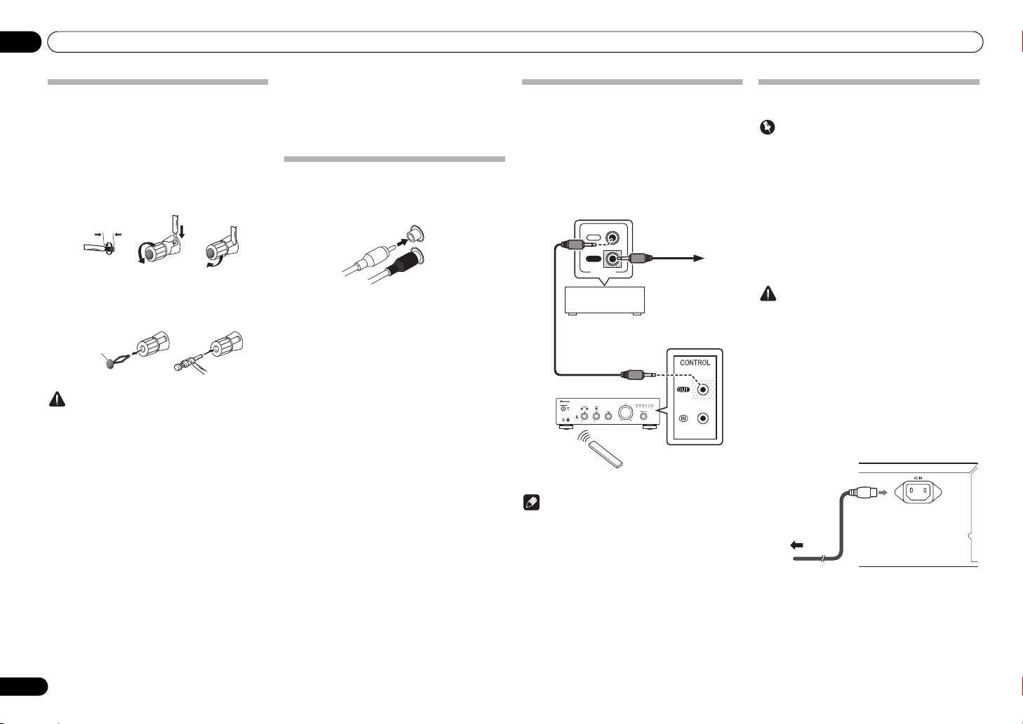
Connecting speaker cables
1 Twist the cable cores.
2 Loosen the nut on the
terminal, and insert the speaker cable into
the exposed hole in the terminal shaft.
3 Retighten the terminal nut.
123
• To use a banana plug connector, pull out the cap on
the terminal nut. Consult the plug instructions for
connection details.
Caution
• When using only one set of speaker terminals
(SPEAKERS A or SPEAKERS B), or when utilizing
bi-wiring connections, the speaker used should
have a nominal impedance between 4 Ω and
16 Ω. When using both sets of terminals, the
connected speakers should have nominal
impedance between 8 Ω and 32 Ω. Consult the
instructions accompanying your speakers for
details regarding the impedance value.
• Make sure the positive and negative (+/–) terminals
on the amplifier match those on the speakers.
• These speaker terminals carry HAZARDOUS live
voltage. To prevent the risk of electric shock when
connecting or disconnecting the speaker cables,
disconnect the power cord before touching any
uninsulated parts.
• Make sure that all the bare speaker wire is twisted
together and inserted fully into the speaker
terminal. If any of the bare speaker wire touches the
back panel it may cause the power to cut off as a
safety measure.
SPEAKERS
Connecting audio cables
Connect the white plug to the left (L) jack, and the red
plug to the right (R) jack. Be sure to insert the plugs fully
into the jacks.
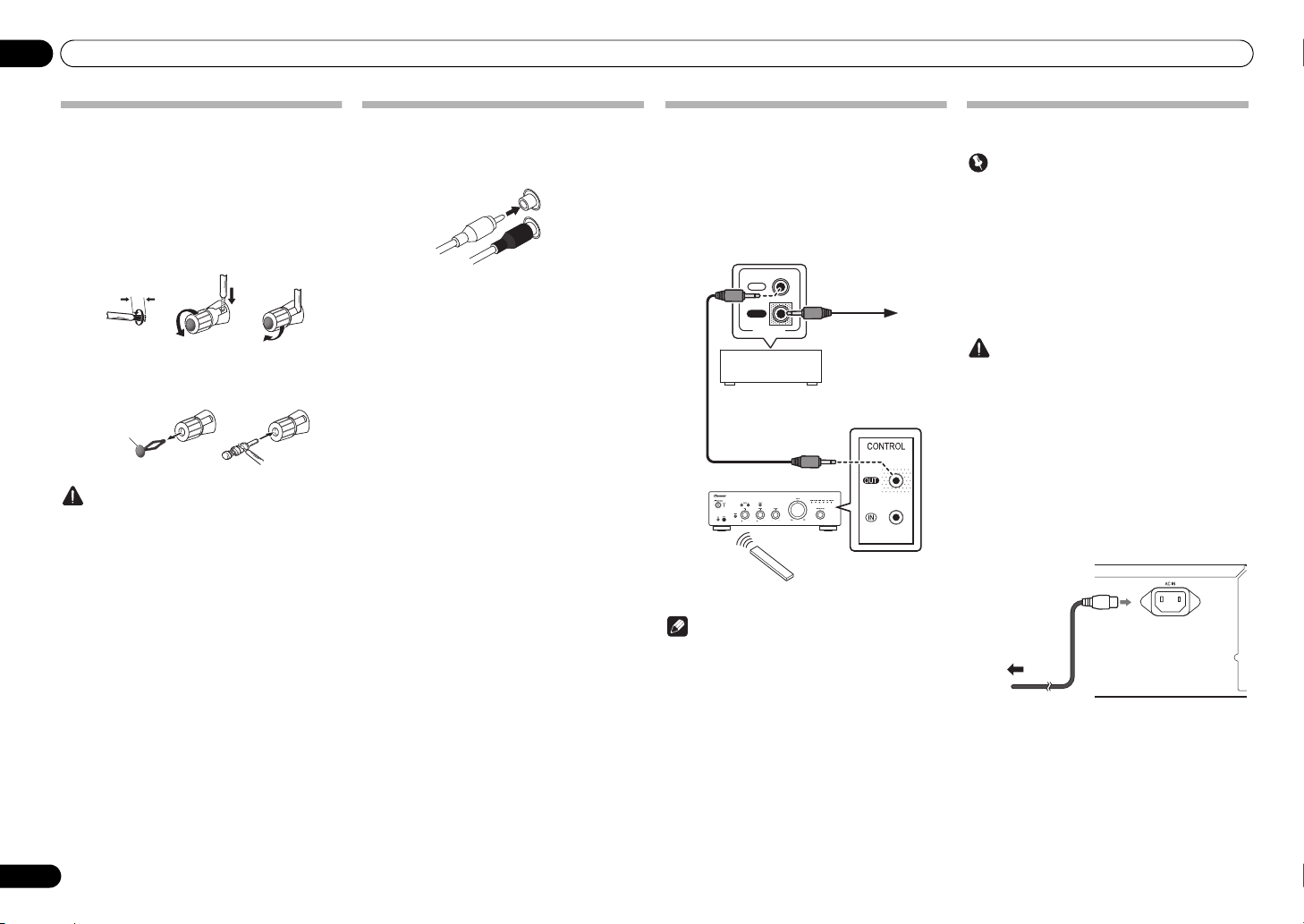
Using centralized control with other
Pioneer components (Except A-10)
Multiple Pioneer components equipped with CONTROL
IN/OUT jacks can be connected to the A-30/A-20 unit,
allowing centralized control of the components via the
rem ote se nsor o n the A -30/A -20. T his al so allows remot e
control of components not equipped with a remote
sensor, or installed in places where the component’s
remote sensor cannot be accessed.
IN
OUT
CONTROL
Note
• For connections use a commercially available
monaural miniplug cord (without resistor).
• When connecting the CONTROL IN/OUT jacks,
commercially available audio cords must also be
used to make analog connections. Merely
connecting the CONTROL IN/OUT jacks alone will
not allow proper system control.
• When a control cord is connected to the A-30/A20’s CONTROL IN jack, the unit cannot be
controlled by pointing the remote control at the A30/A-20 (the remote sensor is automatically
disabled).
Plugging in
Important
• When going on a trip or otherwise not using the
unit for an extended period, always disconnect the
power cord from its outlet. Note that various
internal settings will not be lost even if the power
cord is disconnected from its outlet for an extended
time.
• If it is necessary to detach the power cord, first be
sure to press the
front panel of the unit so the A-30/A-20 is turned
OFF or the A-10 is in standby mode before
detaching the cord.
Caution
• The use of a power cord other than the one provided
will invalidate the warranty, since Pioneer will not
be responsible for any damage incurred. (The
power cord provided with the model A-30 has a
rated current capacity of 10 A, while the cord
provided with the A-20/A-10 has a rated current
capacity of 2.5 A.)
• Do not use any power cord other than the one
supplied with this unit.
• Do not use the supplied power cord for any purpose
other than that described below.
After you’ve finished making all connections, plug the
unit into an AC outlet.
1 Plug the supplied power cord into the
AC IN
socket on the rear panel of the unit.
2 Plug the other end into an AC outlet.
/I
STANDBY/ON button on the
6
En
Controls and displays 03
Chapter 3:
Controls and displays
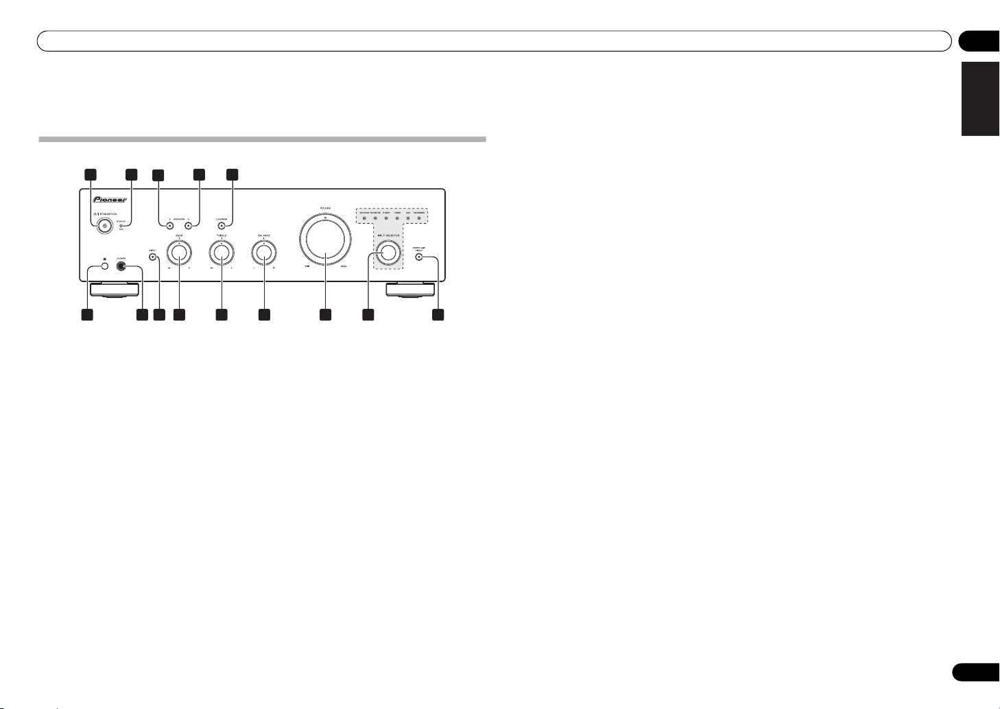
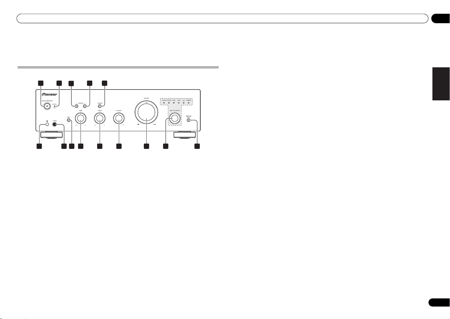
Front panel
1
2 54
3
6
1/I
STANDBY/ON
Switches the amplifier between off and on.
When power is turned on, the power indicator in the
center of the button will light.
• On the A-10 model, this switches the amplifier
between standby and on.
2
STANDBY/APD
When power is set to standby, the indicator lights red.
When the Auto Power Down (APD) function is on, the
indicator lights green (page 11).
3
SPEAKERS A
Use this button to listen to the speaker system
connected to SPEAKERS A terminals.
On : The indicator lights. Sound is heard from the
speaker system. (Sound will also be produced from the
PHONES jack.)
Off : The indicator goes off. No sound is heard from the
speaker system. Set to this position when listening with
headphones.
7
9
8
indicator
button/indicator
10 11 12
4
SPEAKERS B
Use this button to listen to the speaker system
connected to SPEAKERS B terminals.
On : The indicator lights. Sound is heard from the
speaker system. (Sound will also be produced from the
PHONES jack.)
Off : The indicator goes off. No sound is heard from the
speaker system. Set to this position when listening with
headphones.
5
LOUDNESS
Use when listening at low volume levels.
On : The indicator lights: Boosts low and high
frequencies to give added punch to playback even at a
low volume level.
Off : The indicator goes off: Should normally be left in
this position.
• This button does not operate when the DIRECT
button is in the on position.
• When sound volume is raised, the amount of
change produced by the LOUDNESS circuit is
reduced.
A-30
13 14
button/indicator
button/indicator
6 Remote sensor (Except A-10)
Receives the signals from the remote control (page 4).
7
PHONES
Use to connect headphones. No sound is produced
when the POWER AMP DIRECT button is ON.
8 DIRECT button/indicator
On : The indicator lights: When this button is set to ON,
sound signals are output directly, without being passed
through the various adjustment circuits (BASS, TREBLE,
BALANCE, LOUDNESS). This allows reproduction of the
signals with greater fidelity, but it disables any settings
made with the BASS, TREBLE, BALANCE or LOUDNESS
controls.
Off : The indicator goes off: The signal passes through
the various frequency adjusting circuits. When the
indicator is OFF, adjustments can be made with the
BASS, TREBLE, BALANCE, and LOUDNESS controls.
9
BASS
Use to adjust the low-frequency tone. The center position
is the flat (normal) position. When turned to the right,
low-frequency tones are emphasized; when turned to the
left, low-frequency tones are de-emphasized.
• This button does not operate when the DIRECT
button is in the on position.
10
TREBLE
Use to adjust the high-frequency tone. The center
position is the flat (normal) position. When turned to the
right, high-frequency tones are emphasized; when
turned to the left, high-frequency tones are deemphasized.
• This button does not operate when the DIRECT
button is in the on position.
11
BALANCE
Should normally be left in the center position. Adjust
balance if the sound is louder from one of the speakers.
If the right side is louder, turn toward the L (left) position
and if the left side is louder, turn toward the R (right)
position.
• This button does not operate when the DIRECT
button is in the on position.
12 VOLUME control
Use to adjust the volume level. (Also allows adjustment
of the headphone sound volume.)
jack
tone control
tone control
control
13
INPUT SELECTOR
Turn the knob clockwise or counterclockwise so that the
indicator lights for your desired input source. Turning
the knob clockwise causes the lit indicator to right.
Turning counterclockwise causes it to left. When the
remote control’s MUTE button is pressed to mute the
sound, the indicator for the input source selected with
the INPUT SELECTOR knob flashes.
14
POWER AMP DIRECT
knob/indicators
button/indicator
(A-30 only)
Press this button when the A-30 is to be used as a power
amplifier (page 10).
English
DeutschFrançais
Italiano Español Русский
Nederlands
En
7
03 Controls and displays
A-30
1 6
7
28 2
10
9
1311
2
12
2142 23 24 25
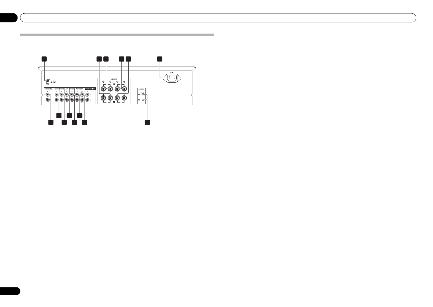
Rear panel
See pages 5-6 for details regarding connections.
1 GND (Turntable ground) terminal
This ground terminal is designed to help reduce noise
when a turntable is connected. It is not a safety ground.
2
SPEAKERS A
3
SPEAKERS B
SPEAKERS B
4
SPEAKERS A
5
6
AC IN
Connect power cord to here and an AC wall socket.
7
PHONO (MM) IN
TUNER IN
8
9
SACD/CD IN
terminals (Right channel)
terminals (Right channel)
terminals (Left channel)
terminals (Left channel)
jack
terminals
terminals
terminals
8
En
10
AUX IN
terminals
11
NETWORK IN
RECORDER IN/OUT
12
POWER AMP DIRECT IN
13
terminals
terminals
terminals (A-30
only)
When using the A-30 as a power amplifier, connect the
pre-amplifier here (page 10).
14
CONTROL IN/OUT
jack (Except A-10)
Controls and displays 03
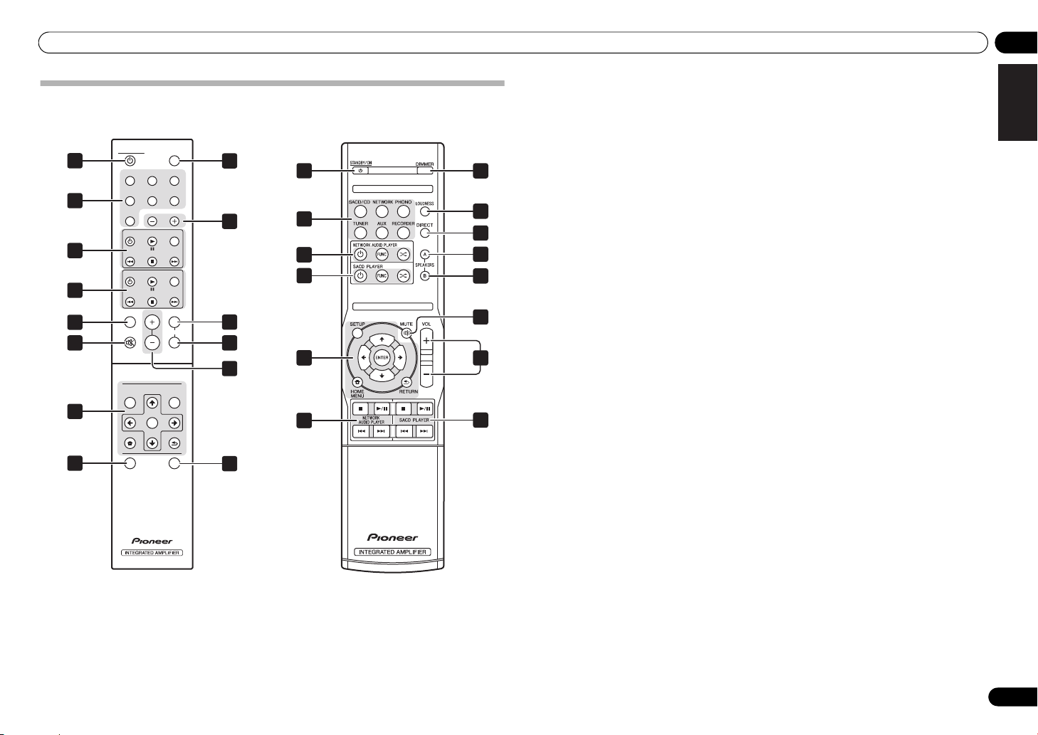
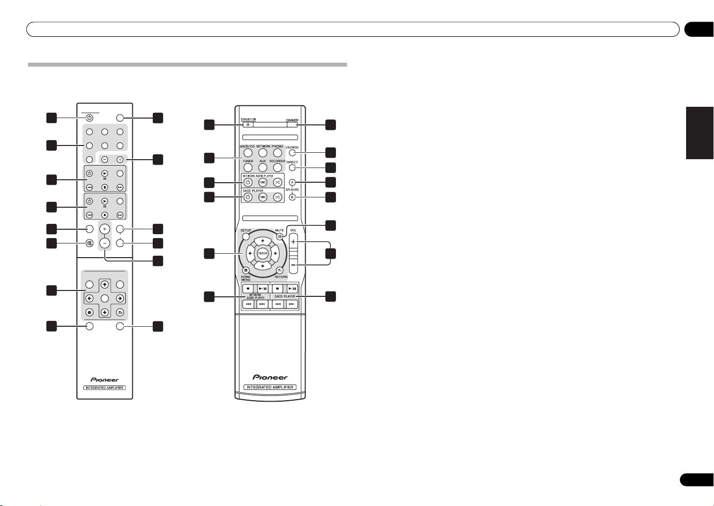
Remote control (Except A-10)
A-30
1
2
3
4
5
6
4
7
STANDBY/ON DIMMER
SACD/CD NETWORK PHONO
TUNER
AUX RECORDER
OPTION
INPUT
DIRECT
VOLUME
ENTER
FUNC
FUNC
A
SPEARKERS
B
SOUNDSETUP
RETURN
APD
SACD PLAYER
NETWORK AUDIO PLAYER
LOUDNESS
MUTE
NETWORK AUDIO PLAYER
HOME MENU
8
9
10
11
12
13
A-20
1
2
34
3
34
34
8
5
7
10
11
6
12
3
1
STANDBY/ON
Switches the amplifier between standby and on.
2 Input selector buttons
Press to select an input source. These select the
component connected to the corresponding input on the
rear panel.
• When the A-30 is connected, the OPTION button is
disabled.
3 SACD PLAYER control buttons
Use to control Pioneer SACD/CD player.
4 NETWORK AUDIO PLAYER control
buttons
Use to control Pioneer network audio player.
5
LOUDNESS
Use to set the loudness circuit ON/OFF (page 7).
6
MUTE
Mutes/unmutes the sound.
7
DIRECT
Press to access Direct listening (page 7).
8
DIMMER
This button allows the illumination of the unit's front
panel indicators to be set in three levels (does not affect
the STANDBY indicator).
9
INPUT +/–
Use to change the input source. The source changes as
below.
SACD/CD NETWORK PHONO TUNER
AUX RECORDER Return to the beginning.
10
SPEAKERS A
Use this button to listen to the speaker system
connected to SPEAKERS A terminals.
11
SPEAKERS B
Use this button to listen to the speaker system
connected to SPEAKERS B terminals.
12
VOLUME +/–
Use to set the listening volume.
13
APD
Use to set the Auto Power Down function to ON/OFF
(page 11).
button/indicator
button/indicator
English
DeutschFrançais
Italiano Español Русский
Nederlands
En
9
04 Operation
3566
62
MENU
iPod
Music>
Extras>
Settings>
Shuffle Songs
Backlight
/I STANDBY/ON
STANDBY
iPod/USB
5V2.1A
PURE AUDIO Hi-Bit 32
FUNCTION
NETWORK AUDIO PLAYER
N-50
SACD/CD player
Network audio player
Turntable
Tuner
iPod dock, etc
CD recorder or
tape deck
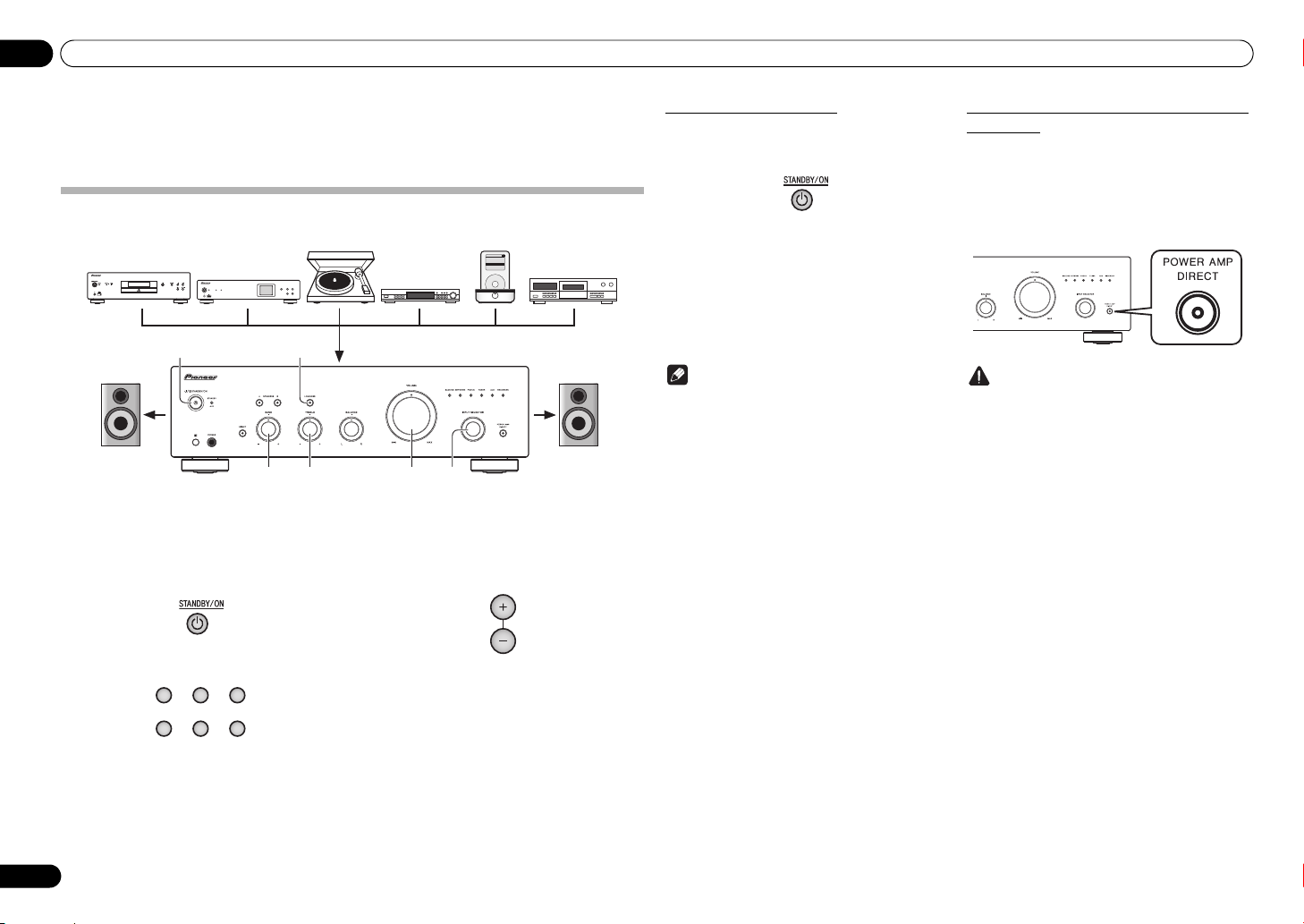
Playback
Playback
Chapter 4:
Operation
Playback
1 Turn on the power of the playback
component.
2 Turn power ON to the unit.
• If the unit is in the standby mode, press the remote
control’s STANDBY/ON button.
3 Select the source you want to playback.
Select the playback component.
• When using the A-30’s remote control, the INPUT
+/– button can be used to select the component.
• When using the front panel controls, rotate the
INPUT SELECTOR knob.
SACD/CD NETWORK PHONO
TUNER AUX RECORDER
4 Start playback of the component you
selected in step 1.
5 Adjust playback volume with
control.
VOLUME
6 Adjust the tone to your preference using
BASS
and
TREBLE
the
LOUDNESS
If the DIRECT button has been set to ON, these controls
are disabled.
button.
controls, and
VOLUME
Set the power to Standby
1 Press the remote control’s
ON
button.
The next time you wish to turn on the power, press the
remote control’s STANDBY/ON button.
• In the case of the A-30/A-20, If the front panel’s
STANDBY/ON button is pressed, the power will
be turned off. In this case, if the power is off,
pressing the remote control’s STANDBY/ON
button will not turn on the power. To turn on the
power again, press the front panel’s STANDBY/
ON button.
Note
• If the power cord is disconnected when the unit is
in the standby mode the unit will turn off, but when
the cord is then reconnected, the unit will not
automatically turn on. After reconnecting the
power cord, press the remote control’s
STANDBY/ON button to turn the power on.
STANDBY/
When using the unit as a power amplifier
(A-30 only)
When a pre-amplifier is connected to the unit’s POWER
AMP DIRECT terminals, the unit can be used as a power
amplifier.
1 Press the
on the front panel of the unit.
The POWER AMP DIRECT indicator will light.
Caution
• When the POWER AMP DIRECT indicator is
lighted, operations change as follows:
– The unit’s front-panel VOLUME, BASS, TREBLE,
– When the POWER AMP DIRECT indicator is
– Sound is not produced from the PHONES jack
• For more information, consult the operating
instructions for the component connected to the A30’s POWER AMP DIRECT terminals.
POWER AMP DIRECT
and BALANCE controls are disabled. These
adjustments are controlled by the component
connected to the unit’s POWER AMP DIRECT
terminals.
lighted, sound volume from the A-30 will
automatically be fixed at its maximum output.
When using this unit as a power amplifier,
check the output level of the component
connected to the POWER AMP DIRECT
terminals and set it to a low level as appropriate
before turning on the POWER AMP DIRECT
indicator. If the sound volume of the component
connected to the POWER AMP DIRECT
terminals is initially set to a high output level,
loud sound may suddenly be output when the
POWER AMP DIRECT indicator lights.
button
and RECORDER OUT terminals.
10
En
Operation 04
SACD/CD player
Network audio player
Turntable
Tuner
iPod dock, etc
Audio recording component
(CD recorder, tape deck, etc.)
Playback
Recording
English
Making an audio recording
You can make an audio recording from any audio source connected to the amplifier.
N-50
/I STANDBY/ON
1 Select the source you want to record.
SACD/CD NETWORK PHONO
TUNER AUX
2 Start recording, then start playback of
the source component.
STANDBY
PURE AUDIO Hi-Bit 32
iPod/USB
5V2.1A
FUNCTION
NETWORK AUDIO PLAYER
To set for automatic standby status (Auto Power Down)
When this condition is set, if no input signal or control operation is detected for 30 minutes, the unit will automatically
enter standby status.
iPod
Music>
Extras>
Settings>
Shuffle Songs
Backlight
MENU
1 If the unit’s power is ON, hold the unit’s front-panel
button depressed simultaneously for three seconds.
When this condition is set to ON, the STANDBY/APD indicator on the unit’s front panel will light green. Press the
buttons again to disable the setting.
DIRECT
button and
LOUDNESS
DeutschFrançais
• This condition can also be set by means of the APD button on the A-30’s remote control.
• The factory default setting is ON.
•Rotating the TREBLE, BASS, BALANCE, or VOLUME controls will not be counted as a control operation for
1
purposes of resetting the Automatic Power-Down 30-minute timer.
Note
• Depending on the device connected, excessive noise produced by the device may be interpreted as an audio
signal, thus preventing the Automatic Power-Down function from operating.
Italiano Español Русский
Restoring all the settings to the factory default settings
1 When power is in standby mode, hold the front-panel’s DIRECT button and
SPEAKERS A button depressed simultaneously for five seconds.
Nederlands
2 Turn power ON to the unit.
11
En

05 Additional information
Chapter 5:
Additional information
Troubleshooting
Incorrect operations are often mistaken for trouble and malfunctions. If you think that there is something wrong with
this component, check the points below. Sometimes the trouble may lie in another component. Investigate the other
components and electrical appliances being used. If the trouble cannot be rectified even after exercising the checks
listed below, ask your nearest Pioneer authorized service center or your dealer to carry out repair work.
• If the unit does not operate normally due to external effects such as static electricity disconnect the power plug
from the outlet and insert again to return to normal operating conditions.
Problem Remedy
The power does not turn on. • Is the power plug disconnected from the power outlet? Connect the power plug
Power turns off. •Is the Auto Power Down function turned ON? If you do not want the power to turn off
During playback, sound stops, and
the
STANDBY/APD
red at about 1 second intervals.
During playback, sound stops, and
the
STANDBY/APD
red at about 2 second intervals.
When power is turned on, the
STANDBY/APD
irregular intervals.
No sound is output when a function is
selected.
No sound from one speaker. •Are the connection cables or speaker cables disconnected on one side? Reconnect
indicator flashes
indicator flashes
indicator flashes at
correctly to its outlet (page 6).
•Is the power cord disconnected from the AC IN connector? Connect the power cord
correctly (page 6).
automatically, disable the Auto Power Down function (page 11).
•The unit’s internal temperature has risen and the safety circuit has operated.
- Turn power OFF, and allow the unit to cool before turning the power ON again.
- Install the unit in a location with better ventilation.
- Confirm that the unit is installed correctly; if the unit is turned on again without
being allowed to cool, the same symptoms may appear (page 4).
•Are you using speakers with impedance values not supported by this unit? Confirm
the speaker’s nominal impedance value (pa ge 6).
•Are any speaker cables loose from the
wires or the surface of the rear panel? Disconnect the power cord and reconnect the
speaker cables correctly (page 6).
•The unit’s circuitry is damaged. Disconnect the power cord and consu lt your dealer
or nearest
Pioneer authorized service center
•A connection cable is disconnected or connected improperly. Check your
connections (page 5).
•Connectors or pin plugs on a cable are dirty. Wipe off any dirt from connectors and
pin plugs.
•Confirm that the unit’s input selector is set to the desired playback component. Set
selector correctly (page 10).
•In the case of the A-30/A-20, press
(page 9).
securely (page 5).
SPEAKERS
terminals and touching other
.
MUTE
on the remote control to turn muting off
Problem Remedy
Can’t operate the remote
control.
Can’t change input source on A-30. •Check whether
•Replace the batt ery (page 4).
•Operate within 7 m, 30° of the remote sensor on the front panel (page 4).
•Remove the obstacle or operate from another position.
•Avoid exposing the remote sensor on the front panel to direct light.
•Is the control cord for one component connected improperly? Confirm correct
connections (page 6).
POWER AMP DIRECT
Cleaning the unit
• Use a polishing cloth or dry cloth to wipe off dust
and dirt.
• When the surface is dirty, wipe with a soft cloth
dipped in some neutral cleanser diluted five or six
times with water, and wrung out well, and then
wipe again with a dry cloth. Do not use furniture
wax or cleansers.
• Never use thinners, benzine, insecticide sprays or
other chemicals on or near this unit, since these
will corrode the surface.
POWER AMP DIRECT
button to turn the function OFF (page 10).
function is ON. If so, press the front panel’s
12
En

Additional information 05
Specifications
Amplifier section
Power output specification is for when power supply is 230 V.
• Continuous power output (both
channels driven at 20 Hz to 20 kHz)
A-30 . . . . . . . . . . . . . . . . . . . . . . . . . . . . . . . . 70 W + 70 W
A-20, A-10 . . . . . . . . . . . . . . . . . . . . . . . . . . . 50 W + 50 W
A-30 . . . . . . . . . . . . . . . . . . . . . . . . . . . . . . . . . 40 W+40 W
A-20, A-10 . . . . . . . . . . . . . . . . . . . . . . . . . . . . 30 W+30 W
Audio section
• Input (Sensitivity/Impedance)
SACD/CD, NETWORK, TUNER, AUX, RECORDER
. . . . . . . . . . . . . . . . . . . . . . . . . . . . . . . . . . . 200 mV/50 kΩ
POWER AMP DIRECT (A-30 only). . . . . . . . . . . 1 V/10 kΩ
PHONO (MM) . . . . . . . . . . . . . . . . . . . . . . . . 2.8 mV/50 kΩ
• Output (Level/Impedance)
RECORDER OUT . . . . . . . . . . . . . . . . . . . .200 mV/2.2 kΩ
PHONES . . . . . . . . . . . . . . . . . . . . . . . . . . . . 250 mV/32 Ω
• Frequency response
SACD/CD, NETWORK, TUNER, AUX, RECORDER
. . . . . . . . . . . . . . . . . . . . . . . . . . . .5 Hz to 100 kHz dB*
PHONO (MM) . . . . . . . . . . . . . .20 Hz to 20 kHz ±0.5 dB*
* Measured with DIRECT button switched on.
• Tone control
(When VOLUME is set to
Bass. . . . . . . . . . . . . . . . . . . . . . . . . . . . .± 10 dB (100 Hz)
Treble. . . . . . . . . . . . . . . . . . . . . . . . . . . .± 10 dB (10 kHz)
• Signal-to-Noise Ratio (IHF SHORTED,
A-NETWORK)
SACD/CD, NETWORK, TUNER, AUX, RECORDER
. . . . . . . . . . . . . . . . . . . . . . . . . . . . . . . . . . . . . . . . 105 dB*
PHONO (MM, 2.8 mV input) . . . . . . . . . . . . . . . . . 77 dB*
* Measured with DIRECT button switched on.
• Speaker load impedance
A, B . . . . . . . . . . . . . . . . . . . . . . . . . . . . . . . . . 4 Ω to 16 Ω
A+B. . . . . . . . . . . . . . . . . . . . . . . . . . . . . . . . . 8 Ω to 32 Ω
Bi-wiring . . . . . . . . . . . . . . . . . . . . . . . . . . . . . 4 Ω to 16 Ω
(THD 0.1 %, 4 Ω)
(THD 0.05 %, 8 Ω)
-
30 dB)
Miscellaneous
Power requirements
. . . . . . . . . . . . . . . . . . . . . . . . . . AC 220 V to 230 V, 50 Hz
Power consumption
A-30 . . . . . . . . . . . . . . . . . . . . . . . . . . . . . . . . . . . . . . 175 W
A-20/A-10. . . . . . . . . . . . . . . . . . . . . . . . . . . . . . . . . . 135 W
In standby . . . . . . . . . . . . . . . . . . . . . . . . . . . . . . . . . 0.3 W
Dimensions
. . . . . . . . . . . . .435 mm (W) x 128 mm (H) x 360 mm (D)
Weight (without package)
A-30 . . . . . . . . . . . . . . . . . . . . . . . . . . . . . . . . . . . . . . 7.9 kg
A-20 . . . . . . . . . . . . . . . . . . . . . . . . . . . . . . . . . . . . . . 7.2 kg
A-10 . . . . . . . . . . . . . . . . . . . . . . . . . . . . . . . . . . . . . . 6.7 kg
Accessories
Remote control (Except A-10) . . . . . . . . . . . . . . . . . . . . . 1
AAA/IEC R03 dry cell batteries (Except A-10) . . . . . . . . 2
Power cord
Warranty card
Operating instructions (This document)
Note
• Specifications and the design are subject to
possible modifications without notice, due to
improvements.
• Corporation and product names mentioned herein
are trademarks or registered trademarks of the
respective corporations.
English
DeutschFrançais
Italiano Español Русский
Nederlands
© 2012 PIONEER CORPORATION.
All rights reserved.
13
En
IMPORTANT
ATTENTION
DANGER D´ELECTROCUTION
NE PAS OUVRIR
Ce symbole de l’éclair, placé dans un
triangle équilatéral, a pour but d’attirer
l’attention de l’utilisateur sur la présence, à
l’intérieur du coffret de l’appareil, de
“tensions dangereuses” non isolées d’une
grandeur suffisante pour représenter un
risque d’électrocution pour les êtres
humains.
Information à destination des utilisateurs sur la collecte et l’élimination des
équipements et batteries usagés
Marquage pour les
équipements
Exemples de marquage
pour les batteries
Pb
Ces symboles qui figurent sur les produits, les emballages et/ou les documents
d’accompagnement signifient que les équipements électriques et électroniques et
batteries usagés ne doivent pas être jetés avec les déchets ménagers et font l’objet
d’une collecte sélective.
Pour assurer l’enlèvement et le traitement appropriés des produits et batteries
usagés, merci de les retourner dans les points de collecte sélective habilités
conformément à la législation locale en vigueur.
En respectant les circuits de collecte sélective mis en place pour ces produits, vous
contribuerez à économiser des ressources précieuses et à prévenir les impacts
négatifs éventuels sur la santé humaine et l’environnement qui pourraient résulter
d’une mauvaise gestion des déchets.
Pour plus d’information sur la collecte et le traitement des produits et batteries
usagés, veuillez contacter votre municipalité, votre service de gestion des déchets
ou le point de vente chez qui vous avez acheté ces produits.
Ces symboles ne sont valables que dans les pays de l’Union Européenne.
Pour les pays n’appartenant pas à l’Union Européenne :
Si vous souhaitez jeter ces articles, veuillez contacter les autorités ou revendeurs
locaux pour connaître les méthodes d’élimination appropriées.
ATTENTION :
POUR ÉVITER TOUT RISQUE
D’ÉLECTROCUTION, NE PAS ENLEVER LE
COUVERCLE (NI LE PANNEAU ARRIÈRE).
AUCUNE PIÈCE RÉPARABLE PAR
L’UTILISATEUR NE SE TROUVE À
L’INTÉRIEUR. CONFIER TOUT ENTRETIEN À
UN PERSONNEL QUALIFIÉ UNIQUEMENT.
Ce point d’exclamation, placé dans un
triangle équilatéral, a pour but d’attirer
l’attention de l’utilisateur sur la présence,
dans les documents qui accompagnent
l’appareil, d’explications importantes du
point de vue de l’exploitation ou de
l’entretien.
D3-4-2-1-1_A1_Fr
K058a_A1_Fr
AVERTISSEMENT
Cet appareil n’est pas étanche. Pour éviter les risques
d’incendie et de décharge électrique, ne placez près de
lui un récipient rempli d’eau, tel qu’un vase ou un pot
de fleurs, et ne l’exposez pas à des gouttes d’eau, des
éclaboussures, de la pluie ou de l’humidité.
D3-4-2-1-3_A1_Fr
AVERTISSEMENT
Avant de brancher l’appareil pour la première, lisez
attentivement la section suivante.
La tension de l’alimentation électrique disponible
varie selon le pays ou la région. Assurez-vous que
la tension du secteur de la région où l’appareil sera
utilisé correspond à la tension requise (par ex. 230
V ou 120 V), indiquée sur le panneau arrière.
D3-4-2-1-4*_A1_Fr
AVERTISSEMENT
Pour éviter les risques d’incendie, ne placez aucune
flamme nue (telle qu’une bougie allumée) sur
l’appareil.
D3-4-2-1-7a_A1_Fr
PRÉCAUTION DE VENTILATION
Lors de l’installation de l’appareil, veillez à laisser un
espace suffisant autour de ses parois de manière à
améliorer la dissipation de chaleur (au moins 30 cm sur
le dessus, 10 cm à l’arrière et 10 cm de chaque côté).
AVERTISSEMENT
Les fentes et ouvertures du coffret sont prévues pour la
ventilation, pour assurer un fonctionnement stable de
l’appareil et pour éviter sa surchauffe. Pour éviter les
risques d’incendie, ne bouchez jamais les ouvertures et
ne les recouvrez pas d’objets, tels que journaux, nappes
ou rideaux, et n’utilisez pas l’appareil posé sur un tapis
épais ou un lit.
D3-4-2-1-7b*_A1_Fr
Milieu de fonctionnement
Température et humidité du milieu de fonctionnement :
De +5 °C à +35 °C (de +41 °F à +95 °F) ; Humidité
relative inférieure à 85 % (orifices de ventilation non
obstrués)
N’installez pas l’appareil dans un endroit mal ventilé ou
un lieu soumis à une forte humidité ou en plein soleil
(ou à une forte lumière artificielle).
D3-4-2-1-7c*_A1_Fr
Ce produit est destiné à une utilisation domestique
générale. Toute panne due à une utilisation autre qu'à
des fins privées (comme une utilisation à des fins
commerciales dans un restaurant, dans un autocar
ou sur un bateau) et qui nécessite une réparation
sera aux frais du client, même pendant la période de
garantie.
K041_A1_Fr
Merci d’avoir acheté ce produit
Pioneer.
Veuillez lire entièrement ce mode d’emploi afin de
pouvoir faire fonctionner correctement le modèle que
vous avez choisi. Après avoir fini la lecture du mode
d’emploi, placez-le dans un endroit sûr afin de pouvoir
vous y référer plus tard
.
Table des
Si la fiche d’alimentation secteur de cet appareil ne
convient pas à la prise secteur à utiliser, la fiche doit
être remplacée par une appropriée. Ce
remplacement et la fixation d’une fiche secteur sur le
cordon d’alimentation de cet appareil doivent être
effectués par un personnel de service qualifié. En cas
de branchement sur une prise secteur, la fiche de
coupure peut provoquer une sérieuse décharge
électrique. Assurez-vous qu’elle est éliminée
correctement après sa dépose.
L’appareil doit être déconnecté en débranchant sa
fiche secteur au niveau de la prise murale si vous
prévoyez une période prolongée de non utilisation
(par exemple avant un départ en vacances).
D3-4-2-2-1a_A1_Fr
ATTENTION
L’interrupteur /I STANDBY/ON de cet appareil ne
coupe pas complètement celui-ci de sa prise secteur.
Comme le cordon d’alimentation fait office de
dispositif de déconnexion du secteur, il devra être
débranché au niveau de la prise secteur pour que
l’appareil soit complètement hors tension. Par
conséquent, veillez à installer l’appareil de telle
manière que son cordon d’alimentation puisse être
facilement débranché de la prise secteur en cas
d’accident. Pour éviter tout risque d’incendie, le
cordon d’alimentation sera débranché au niveau de
la prise secteur si vous prévoyez une période
prolongée de non utilisation (par exemple avant un
départ en vacances).
D3-4-2-2-2a*_A1_Fr
NOTE IMPORTANTE SUR LE CABLE D’ALIMENTATION
Tenir le câble d’alimentation par la fiche. Ne pas
débrancher la prise en tirant sur le câble et ne pas
toucher le câble avec les mains mouillées. Cela risque de
provoquer un court-circuit ou un choc électrique. Ne pas
poser l’appareil ou un meuble sur le câble. Ne pas pincer
le câble. Ne pas faire de noeud avec le câble ou l’attacher
à d’autres câbles. Les câbles d’alimentation doivent être
posés de façon à ne pas être écrasés. Un câble abîmé
peut provoquer un risque d’incendie ou un choc
électrique. Vérifier le câble d’alimentation de temps en
temps. Contacter le service après-vente PIONEER le plus
proche ou le revendeur pour un remplacement.
S002*_A1_Fr
(A-30 uniquement)
ATTENTION:
SURFACE CHAUDE. NE PAS TOUCHER.
La surface supérieure du dissipateur de
chaleur interne peut devenir très chaude
lorsque ce produit fonctionne en
permanence.
matières
01 Préparatifs
Contenu de la boîte . . . . . . . . . . . . . . . . . . . . . . . .4
Chargement des piles de la télécommande
(à l’exception de l’A-10) . . . . . . . . . . . . . . . . . . . . .4
Utilisation de la télécommande . . . . . . . . . . . . . . . .4
Installation de l’amplificateur . . . . . . . . . . . . . . . .4
02 Raccordement
Raccordements des câbles . . . . . . . . . . . . . . . . . . 5
A propos de “bi-câblage (bi-wiring)”. . . . . . . . . . . .5
Connexion des câbles d’enceinte. . . . . . . . . . . . . . 6
Raccordement des câbles audio . . . . . . . . . . . . . . 6
Commande centralisée avec d’autres composants
Pionner (à l’exception de l’A-10) . . . . . . . . . . . . . . 6
Branchement. . . . . . . . . . . . . . . . . . . . . . . . . . . . .6
03 Commandes et afficheur
Panneau avant. . . . . . . . . . . . . . . . . . . . . . . . . . . .7
Panneau arrière. . . . . . . . . . . . . . . . . . . . . . . . . . .8
Télécommande (à l’exception de l’A-10). . . . . . . . .9
04 Fonctionnement
Lecture . . . . . . . . . . . . . . . . . . . . . . . . . . . . . . . . 10
Réglage de la puissance sur la mise en veille . . . .10
Lorsque vous utilisez l’unité comme amplificateur
(A-30 uniquement). . . . . . . . . . . . . . . . . . . . . . . . . 10
Réalisation d’un enregistrement audio . . . . . . . . 11
Pour régler un statut de veille automatique
(fonction de mise hors tension automatique). . . .11
Pour restaurer tous les réglages sur
les valeurs par défaut. . . . . . . . . . . . . . . . . . . . . . 11
05 Informations supplémentaires
Guide de dépannage . . . . . . . . . . . . . . . . . . . . . . 12
Nettoyage de l’unité. . . . . . . . . . . . . . . . . . . . . . . 12
Spécifications . . . . . . . . . . . . . . . . . . . . . . . . . . .13
3
01 Préparatifs
Chapitre 1 :
Préparatifs
Contenu de la boîte
Veuillez confirmer que les accessoires suivants sont
présents dans la boîte quand vous l’ouvrez.
• Télécommande (à l’exception de l’A-10)
• Piles sèches AAA/IEC R03 x2 (à l’exception de
l’A-10)
• Cordon d’alimentation
• Carte de garantie
• Mode d’emploi (ce document)
Remarque
• Les illustrations des instructions opérationnelles
peuvent avoir été modifiées ou simplifiées dans le
but de clarification et en conséquence peuvent
différer de l’apparence actuelle du produit.
• Les illustrations utilisées ici représentent
principalement l’A-30.
Chargement des piles de la
télécommande
(à l’exception de l’A-10)
1 Ouvrez le couvercle arrière.
A-30
A-20
2 Placez les piles neuves, en faisant
correspondre la polarité à celle du boîtier.
A-30
A-20
3 Fermez le couvercle arrière.
A-30
Les piles incluses avec l’unité ont été fournies pour
permettre de contrôler le fonctionnement du produit et
ne dureront pas longtemps. Nous recommandons
d’utiliser des piles alcalines qui ont une durée de vie
utile plus longue.
A-20
Attention
Toute utilisation incorrecte des piles peut entraîner des
accidents, par exemple une fuite ou une explosion.
Respectez les précautions suivantes :
• Lorsque vous placez les piles, prenez soin de ne pas
endommager les ressorts des bornes des piles .
• Ne pas utiliser de piles autres que celles qui sont
indiquées. Ne pas utiliser non plus une pile neuve
avec une pile usée.
• Lorsque vous installez les piles dans la
télécommande, orientez-les batteries dans la
bonne direction en respectant la polarité ( et ).
• Ne pas chauffer, ni démonter, ni ne jeter les piles
dans le feu ou l’eau.
• La tension des piles peut différer l’une de l’autre et
cela même si leur type et forme sont identiques.
Utiliser ensemble uniquement des piles du même
type.
• Pour éviter que les piles ne fuient, enlever les piles
lorsque le produit n’est pas censé être utilisé
pendant une période prolongée (à savoir 1 mois ou
plus). Si les piles ont fuit, nettoyer soigneusement
l’intérieur du compartiment et placer ensuite les
piles. Si une pile fuit et que du liquide entre en
contact avec votre peau, nettoyer à grande quantité
d’eau.
• Lorsque vous jetez des piles usées, veuillez vous
conformer aux normes gouvernementales ou à la
réglementation des institutions publiques
environnementales en vigueur dans votre pays ou
région.
Utilisation de la télécommande
La télécommande a une portée d’environ 7 m avec un
angle de 30° par rapport au capteur de télécommande.
• La télécommande risque de ne pas fonctionner
correctement si la lumière du soleil ou une lampe
fluorescente puissante éclaire le capteur de
l’appareil.
• Les télécommandes de différents appareils
peuvent interférer entre elles. Evitez d’utiliser des
télécommandes commandant d’autres
équipements situés à proximité de cet appareil.
• Remplacez les piles lorsque vous constatez une
diminution de la portée de fonctionnement de la
télécommande.
Installation de l’amplificateur
Lors de l’installation de l’appareil, assurez-vous que ce
dernier est posé sur une surface plane et stable.
•
N’installez pas l’appareil dans les endroits suivants :
– sur un téléviseur couleur (les images à l’écran
pourraient être déformées)
– à proximité d’une platine à cassettes (ou d’un
appareil qui produit un champ magnétique). Le son
pourrait s’en trouver affecté.
– à la lumière directe du soleil
– à l’humidité
– à des températures extrêmes
– en présence de vibrations ou autres mouvements
– à la poussière
– à la fumée ou aux émanations graisseuses
(cuisine par ex.)
• Ne pas installer l’unité sur un divan ou tout autre
objet/matériau ayant des caractéristiques
absorbantes sous risque d’affecter la qualité du
son.
AVERTISSEMENT
• N’utilisez ni ne conservez les piles sous la lumière
directe du soleil ou dans un endroit excessivement
chaud, comme une voiture ou à proximité d’un
appareil de chauffage. Les piles risqueraient de
fuir, de surchauffer, d’exploser ou de s’enflammer.
Leur durée de vie ou leur performance pourrait
également être réduite.
Gardez à l’esprit ce qui suit lorsque vous utilisez la
télécommande :
• Assurez-vous de l’absence d’obstacles entre la
télécommande et le capteur de l’appareil.
30 °
30 °
7 m
4
Fr
Raccordement 02
Chapitre 2 :
Raccordement
Raccordements des câbles
Attention
• Avant d’effectuer ou de modifier les raccordements, mettez l’appareil hors tension et débranchez le cordon
d’alimentation de la prise secteur.
• Connectez le cordon d’alimentation après avoir effectué toutes les connexions entre les appareils.
Lecteur SACD/CD
R
L
Lecteur audio réseau
R
L
A-30
uniquement
Prises PRE OUT sur le
pré-amplificateur ou
amplificateur AV
PRE OUT
L
L
R
R
Système d’enceinte B
Gauch
Droite
Panneau arrière A-30
Attention
•La borne SIGNAL GND est fournie pour réduire le
bruit lors de la connexion de l’unité aux
composants, tels que la platine.
• Ne pas connecter les bornes PHONO (MM) à un
autre composant qu’une platine; ne pas connecter
non plus une platine dotée d’un égalisateur intégré.
Un son émis trop fort peut se produire, ce qui
endommagerait les enceintes ou les autres
appareils.
• Les bornes de l’unité
pour être utilisées avec des des
cartouches de type MM (à aimant mobile). Ne pas
utiliser les les
bobine mobile).
• Assurez-vous de ne pas plier les câbles par dessus
cette unité (comme indiqué dans l’illustration). Si
cela se produit, le champ magnétique produit par
les transformateurs dans cette unité peut
provoquer un ronflement des enceintes.
PHONO (MM)
platines dotée
ont été conçues
platines dotée
s de
s de cartouches MC (à
• Au cours de la lecture, assurez-vous que les
boutons SPEAKERS A et SPEAKERS B sont sur
Marche (ON) (page 7).
Système des
Droite
HIGH
LOW
Panneau
arrière A-30
Enlevez la tige de
court-circuit entre
les bornes + et –.
Système des
Gauch
HIGH
LOW
English
DeutschFrançais
Italiano Español Русский
• Les bornes de l’unité POWER AMP DIRECT ne
LRL
LRL
R
Platine
R
LRLRL
Syntoniseur
L
R
R
L
R
AUDIO
RL
OUTPUT
L
L
R
R
OUTPUT
iPod
Music>
Extras>
Settings>
Shuffle Songs
Backlight
MENU
Station d’accueil
iPod, etc.
PLAY
L
R
Enregistreur CD
ou à bande
REC
L
R
Cordon
d’alimentation
L
R
Droite
Système d’enceinte A
Gauch
doivent jamais être branchées à des connecteurs
autres que PRE-AMP OUT.
• Si votre platine dispose d’un fil de mise à la terre,
fixez-le à la borne de terre de cet amplificateur.
Remarque
• Lors de la connexion d’un enregistreur à bande, le
bruit de fond peut être perçu, selon l’emplacement
de l’installation. Ce bruit provient d’une fuite du
transformateur de l’amplificateur. Dans ce cas,
changez l’emplacement de l’installation ou
distancez davantage la platine de l’amplificateur.
• iPod est une marque commerciale d’Apple Inc.,
enregistrées aux États-Unis et dans d’autres pays.
A propos de “bi-câblage (bi-wiring)”
Cette unité peut être utilisée avec des enceintes
prenant en charge le bi-câblage. Toujours raccorder
correctement la haute fréquence et la basse
fréquence.
Attention
• Lorsque vous utilisez un bi-câblage pour connecter
les enceintes, assurez-vous d’enlever les tiges de
court-circuit HIGH et LOW fournies avec les
haut-parleurs pour ne pas créer d’effets adverses
sur l’amplificateur. Pour de plus amples
informations, consultez les instructions fournies
avec les enceintes.
• Lorsque vous utilisez des enceintes avec des
circuits de réseau amovibles, si le réseau est
enlevé, aucun effet ne se produira et les enceintes
peuvent subir des dommages.
• Vous pouvez alternativement connecter les bornes
SPEAKERS A sur HIGH et celles sur LOW
SPEAKERS B (à l’inverse de ce qui est illustré).
Nederlands
5
Fr
02 Raccordement
Connexion des câbles d’enceinte
1 Entortillez l’âme des câbles.
2 Desserrez l’écrou sur la borne
et introduisez le câble de l’enceinte dans le
trou exposé dans la borne.
3 Resserrez l’écrou de la borne.
123
10 mm
• Pour utiliser un connecteur à fiche banane, enlevez
le capuchon situé sur l’écrou de la borne. Pour de
plus amples informations, consultez les
instructions relatives à la fiche.
Capuc
Attention
• Lorsque vous utilisez uniquement un jeu de
bornes de l’enceinte (SPEAKERS A ou SPEAKERS
B), ou lorsque vous utilisez des connexions
bi-câblage, l’enceinte utilisée doit disposer
d’une impédance nominale entre 4 Ω et 16 Ω.
Lorsque vous utilisez des jeux de bornes, les
enceintes connectées doivent disposer d’une
impédance nominale entre 8 Ω et 32 Ω. Pour de
plus amples informations sur la valeur de
l’impédance, consultez les instructions jointes
aux enceintes.
• Vérifiez que les bornes positive et négative (+/–) sur
l’amplificateur correspondent à celles des
enceintes.
• Les bornes des haut-parleurs sont sous une
tension ACTIVE DANGEREUSE. Pour éviter tout
risque de décharge électrique lors du branchement
et du débranchement des câbles d’enceinte,
débranchez le cordon d’alimentation avant de
toucher des parties non isolées.
SPEAKERS
• Assurez-vous que tous les fils dénudés d’enceinte
sont entortillés ensemble et totalement introduits
dans la borne de l’enceinte. Si l’un des fils dénudés
entre en contact avec le panneau arrière,
l’alimentation sera automatiquement coupée par
mesure de sécurité.
Raccordement des câbles audio
Connectez la fiche blanche à la prise gauche (L) et la
fiche rouge à la prise droite (R). Assurez-vous de bien
brancher les fiches dans les prises.
Gauche
(blanche)
Droite (rouge)
Commande centralisée avec d’autres
composants Pionner (à l’exception de
l’A-10)
De nombreux composants Pionneer dotés de prises
CONTROL IN/OUT peuvent être connectés aux unités
A-30/A-20 centralisant la commande des composants
via le télécapteur sur l’A-30/A-20. Cette centralisation
permet d’utiliser une télécommande dont les
composants ne sont pas munis d’un télécapteur ou sont
installés à des emplacements inaccessibles par le
télécapteur.
IN
OUT
CONTROL
Vers d’autres
composants Pioneer
munis de prises
CONTROL IN/OUT
A-30/A-20
Télécommande
A-30/A-20
Remarque
• Pour établir la connexion, utilisez un cordon minifiche mono en vente dans le commerce (sans
résistance).
•
Lors de la connexion des prises
des cordons audio en vente dans le commerce
doivent être utilisés pour établir les connexions
analogiques. La connexion des prises CONTROL
IN/OUT ne suffit pas à à assurer un contrôle
adéquat du système.
• Lorsqu’un cordon de commande est connecté à la
prise de l’A-30/A-20 CONTROL IN, il est impossible
de contrôler l’unité en pointant la télécommande à
l’A-30/A-20 (le télécapteur est automatiquement
désactivé).
Vers d’autres
composants
Pioneer munis
d’une prise
CONTROL IN
Visez la télécommande
en direction du capteur
sur l’A-30/A-20.
CONTROL IN/OUT
Branchement
Important
• Lorsque vous devez vous absenter ou quelle que
soit la situation où l’unité ne sera pas utilisée
pendant une longue durée, toujours déconnecter le
cordon d’alimentation de ses prises. Les réglages
in tern es s ont tou jou rs c onse rvé s et cel a mê me s i le
cordon d’alimentation est déconnecté de sa prise
pendant une longue période.
• Si le cordon d’alimentation doit être déconnecté,
assurez-vous d’appuyer sur le bouton
/I
STANDBY/ON sur le panneau avant de l’unité
de manière à ce que l’A-30/A-20 soit sur Arrêt (OFF)
ou l’A-10 en mode d’attente avant de retirer le
cordon.
Attention
•
L’utilisation d’un cordon d'alimentation autre que
celui fourni, annule la garantie. En conséquence,
’endosse aucune responsabilité pour les
Pion ner n
dommages qui pourraient survenir. (Le courant
nominal du cordon d'alimentation fourni avec le
modèle A-30 est de 10 A alors que le cordon fourni
avec A-20/A-10 est de 2,5 A).
• Ne pas utiliser de cordon d’alimentation autre que
celui fourni avec cette unit.
• Ne pas utiliser le cordon d’alimentation fourni pour
un usage que celui qui est décrit ci-dessous.
Après avoir effectué toutes les connexions, branchez
l’unité dans une prise CA.
Panneau arrière A-30
Vers la prise CA
,
Cordon d’alimentation
1 Branchez le cordon d’alimentation dans
la prise
AC IN
située sur le panneau arrière
de l’unité.
2 Branchez l’autre extrémité dans la prise
CA.
6
Fr
Commandes et afficheur 03
Chapitre 3 :
Commandes et afficheur
Panneau avant
1
2 54
3
6
1/I
STANDBY/ON
Ce bouton permet de mettre l’amplificateur sous/hors
tension.
Lors de la mise sous tension, l’indicateur au centre du
bouton s’allume.
• Sur un modèle A-10, ce bouton permet de mettre
l’amplificateur sous tension et en veille.
2 Indicateur
Lorsque l’alimentation est en mode veille, l’indicateur
s’allume en rouge. Lorsque la fonction de mise hors
tension automatique (APD) est activée, l’indicateur
s’allume en vert (page 11).
3 Bouton/indicateur
Ce bouton permet d’écouter le système d’enceinte
connecté aux bornes SPEAKERS A.
On : L’indicateur s’allume. Le son est entendu du
système d’enceinte. (Le son sera également émis de la
prise PHONES).
Off : L’indicateur s’éteint. Aucun son n’est entendu du
système d’enceinte. Réglez à cette position lorsque vous
utilisez des écouteurs.
7
9
8
STANDBY/APD
SPEAKERS A
10 11 12
4 Bouton/indicateur
Ce bouton permet d’écouter le système d’enceinte
connecté aux bornes SPEAKERS B.
On : L’indicateur s’allume. Le son est entendu du
système d’enceinte. (Le son sera également émis de la
prise PHONES).
Off : L’indicateur s’éteint. Aucun son n’est entendu du
système d’enceinte. Réglez à cette position lorsque vous
utilisez des écouteurs.
5 Bouton/indicateur
Utilisez lorsque vous utilisez à des niveaux faibles.
On : L’indicateur s’allume : Augmente les fréquences
hautes et basses pour donner du punch aux lectures
même à niveau sonore faible.
Off : L’indicateur s’éteint: Doit en principe rester dans
cette position.
• Ce bouton ne fonctionne pas lorsque le bouton
DIRECT est en position de marche.
• Lorsque vous augmentez le son, la quantité de
changement produit par le circuit LOUDNESS est
réduite.
13 14
A-30
SPEAKERS B
LOUDNESS
6 Capteur de télécommande
à l’exception de l’A-10
(
Reçoit les signaux émis par la télécommande (page 4).
7Prise
Utilisez pour connecter des écouteurs. Pas de son
produit lorsque le bouton POWER AMP DIRECT est sur
ON.
8 Bouton/indicateur DIRECT
On : L’indicateur s’allume : Lorsque ce bouton est sur
ON, les signaux sonores sont émis directement sans
passer par les divers circuits de réglage (BASS, TREBLE,
BALANCE, LOUDNESS). Les signaux sont ainsi
reproduits très fidèlement mais les réglages effectués
avec les commandes BASS, TREBLE, BALANCE ou
LOUDNESS sont ignorés.
Off : L’indicateur s’éteint: Le signal passe par divers
circuits d’ajustement de fréquence. Lorsque l’indicateur
est sur OFF, les réglages peuvent être effectués avec les
commandes BASS, TREBLE, BALANCE et LOUDNESS.
9 Commande de la tonalité
Utilisez pour régler la tonalité basse fréquence. La
position centrale correspond à une position plate
(normale). Lorsque vous tournez sur la droite, les
tonalités basse fréquence sont accentuées; lorsque
vous tournez sur la gauche, les tonalités basse
fréquence sont atténuées.
10 Commande de la tonalité
Utilisez pour régler la tonalité haute fréquence. La
position centrale correspond à une position plate
(normale). Lorsque vous tournez sur la droite, les
tonalités haute fréquence sont accentuées; lorsque vous
tournez sur la gauche, les tonalités haute fréquence sont
atténuées.
11
Doit en principe rester au centre. Réglez l’équilibre si le
son est plus fort d’une enceinte que de l’autre. Si le côté
droit est plus fort, tournez vers la gauche (L) et si le côté
gauche est plus fort, tournez vers la droite (R).
PHONES
• Ce bouton ne fonctionne pas lorsque le bouton
DIRECT est en position de marche.
• Ce bouton ne fonctionne pas lorsque le bouton
DIRECT est en position de marche.
Commande BALANCE
• Ce bouton ne fonctionne pas lorsque le bouton
DIRECT est en position de marche.
)
BASS
TREBLE
12 Commandes du VOLUME
Utilisez pour régler le niveau du volume. (Permet
également d’effectuer des réglages du volume sonore
des écouteurs.)
13 Touche/indicateur
Tournez le bouton dans le sens horaire ou anti-horaire
de manière à ce que l’indicateur s’allume pour la source
d’entrée souhaitée. Tournez le bouton dans le sens
horaire pour que l’indicateur s’allume sur la droite.
Tournez dans le sens anti-horaire pour que l’indicateur
s’allume sur la gauche. Lorsque vous appuyez sur le
bouton de la télécommande MUTE pour mettre le son
en sourdine, l’indicateur de la source d’entrée
sélectionné avec le bouton INPUT SELECTOR se met à
clignoter.
14 Bouton/indicateur
(A-30 uniquement)
Appuyez sur ce bouton lorsque l’A-30 sera utilisé
comme amplificateur de la puissance (page 10).
INPUT SELECTOR
POWER AMP DIRECT
English
DeutschFrançais
Italiano Español Русский
Nederlands
7
Fr

03 Commandes et afficheur
Panneau arrière
Pour de plus amples informations sur les connexions, voir les pages 5-6.
1 6
2142 23 24 25
28 2
10
2
12
7
9
1311
1 Borne GND (mise à la terre de la platine)
Cette borne de terre a été conçue pour réduire le bruit
lorsqu’une platine est branchée. Il ne s’agit pas d’une
mise à la terre de sécurité.
2
SPEAKERS A
3
SPEAKERS B
SPEAKERS B
4
SPEAKERS A
5
6Prise
Connectez le cordon d’alimentation ici et à une prise
murale CA.
7
PHONO (MM)
TUNER
8
9
SACD/CD
bornes (canal droit)
bornes (canal droit)
bornes (canal gauche)
bornes (canal gauche)
AC IN
IN bornes
IN bornes
IN bornes
A-30
10
AUX
IN bornes
11
NETWORK
RECORDER IN/OUT
12
POWER AMP DIRECT
13
(A-30 uniquement)
Lorsque vous utilisez l’A-30 comme amplificateur de la
puissance, connectez le pré-amplificateur ici (page 10).
14
CONTROL IN/OUT
(à l’exception de l’A-10)
IN bornes
bornes
IN bornes
prise
8
Fr
Commandes et afficheur 03
1
STANDBY/ON
Télécommande (à l’exception de l’A-10)
A-30
1
2
3
4
5
6
4
7
STANDBY/ON DIMMER
SACD/CD NETWORK PHONO
TUNER
AUX RECORDER
OPTION
INPUT
DIRECT
VOLUME
ENTER
FUNC
FUNC
A
SPEARKERS
B
SOUNDSETUP
RETURN
APD
SACD PLAYER
NETWORK AUDIO PLAYER
LOUDNESS
MUTE
NETWORK AUDIO PLAYER
HOME MENU
8
9
10
11
12
13
A-20
1
2
34
3
34
34
8
5
7
10
11
6
12
3
Cette touche permet d’allumer l’amplificateur et de le
mettre en veille.
2 Boutons de sélection des entrées
Appuyez sur l’une de ces boutons pour sélectionner une
source d’entrée. Elles sélectionnent le composant
raccordé à l’entrée correspondante sur le panneau
arrière.
• Lorsque l’A-30 est connecté, le bouton OPTION est
désactivé.
3 Boutons de commande du SACD PLAYER
Permet de contrôler le lecteur SACD/CD Pioneer.
4 Boutons de commande du AUDIO
PLAYER DE RÉSEAU
Permet de contrôler le lecteur Pioneer audio en réseau.
5
LOUDNESS
Utilisez pour activer/désactiver (ON/OFF) (page 7) le
circuit de la puissance sonore.
6
MUTE
Permet de couper/restaurer le son.
7
DIRECT
Permet d’accéder à la fonction d’écoute en mode direct
(page 7).
8
DIMMER
Ce bouton permet d’allumer les indicateurs du panneau
avant de l’unité pour régler les trois niveaux (aucune
incidence sur l’indicateur STANDBY).
9
INPUT +/–
Permet de changer la source d’entrée. La source change
tel qu’indiqué ci-dessous.
SACD/CD NETWORK PHONO TUNER
AUX RECORDER Permet de revenir au début.
10
SPEAKERS A
Ce bouton permet d’écouter le système d’enceinte
connecté aux bornes SPEAKERS A.
11
SPEAKERS B
Ce bouton permet d’écouter le système d’enceinte
connecté aux bornes SPEAKERS B.
12
VOLUME +/–
Permet de régler le volume d’écoute.
13
APD
Permet d’activer/désactiver la fonction de hors tension
automatique (page 11).
bouton/indicateur
bouton/indicateur
English
DeutschFrançais
Italiano Español Русский
Nederlands
9
Fr
04 Fonctionnement
Chapitre 4 :
Fonctionnement
Lecture
Platine
Lecteur SACD/CD
Lecture
1 Mettez sous tension le composant de
lecture.
2 Mettez l’unité sous tension.
• Si l’unité est en mode de veille, appuyez sur le
bouton de la télécommande STANDBY/ON.
3 Sélectionnez la source que vous
souhaitez lire.
Sélectionnez le composant de lecture.
• Lorsque vous utilisez la télécommande de l’A-30, le
bouton INPUT +/– peut être utilisé pour la sélection
du composant.
Lecteur audio réseau
/I STANDBY/ON
STANDBY
PURE AUDIO Hi-Bit 32
iPod/USB
5V2.1A
SACD/CD NETWORK PHONO
TUNER AUX RECORDER
N-50
NETWORK AUDIO PLAYER
FUNCTION
62
Station d’accueil iPod, etc.
Syntoniseur
iPod
Music>
Extras>
Settings>
Shuffle Songs
Backlight
MENU
Enregistreur CD
ou à bande
Lecture
3566
• Lorsque vous utilisez les commandes du panneau
avant, tournez le bouton INPUT SELECTOR.
4 Débutez la lecture du composant que
vous avez sélectionné dans l’étape 1.
5 Réglez le volume de la lecture avec la
commande
VOLUME
.
VOLUME
6 Ajustez la tonalité à votre choix à l’aide
des commandes
LOUDNESS
bouton
Si le bouton DIRECT a été réglé sur ON, ces commandes
sont désactivées.
BASS
.
et
TREBLE
et du
Réglage de la puissance sur la mise en
veille
1 Appuyez sur le bouton de la
télécommande
La prochaine fois que vous remettrez sous tension,
appuyez sur le bouton STANDBY/ON de la
télécommande.
• Dans le cas de l’A-30/A-20, si le bouton
STANDBY/ON est appuyé, l’unité s’éteint. Dans
ce cas, si l’alimentation est coupée, vous ne
pourrez pas remettre sous tension en appuyant sur
le bouton de la télécommande STANDBY/ON.
Pour remettre sous tension, appuyez sur le bouton
du panneau avant STANDBY/ON.
Remarque
• Si le cordon de l’alimentation n’est pas branché
lorsque l’unité est en mode de veille, l’unité
s’éteindra. Toutefois lorsque le cordon est
rebranché, l’unité ne se remettra pas
automatiquement en marche. Après la
rebranchement du cordon d’alimentation, appuyez
sur le bouton de la télécommande
STANDBY/ON pour remettre sous tension.
STANDBY/ON
.
Lorsque vous utilisez l’unité comme
amplificateur (A-30 uniquement)
Lorsqu’un pré-amplificateur est connecté aux bornes de
l’unité POWER AMP DIRECT, l’unité peut être utilisée
comme amplificateur de puissance.
1 Appuyez sur le bouton
DIRECT
situé sur le panneau avant de
l’unité.
L’indicateur POWER AMP DIRECT s’allume.
Attention
• Lorsque l’indicateur POWER AMP DIRECT
s’allume, les opérations changent comme suit :
– Le panneau avant VOLUME de l’unité, BASS,
TREBLE et les commandes BALANCE sont
désactivés. Ces réglages sont contrôlés par le
composant connecté aux bornes de l’unité
POWER AMP DIRECT.
– Lorsque l’indicateur POWER AMP DIRECT
s’allume, le volume sonore de l’A-30 est
automatiquement fixé à sa puissance maximale.
Lorsque vous utilisez cet appareil comme
amplificateur de puissance, vérifiez le niveau de
sortie du composant connecté aux bornes
POWER AMP DIRECT et réglez-le à un niveau
bas, le cas échéant, avant d’allumer l’indicateur
POWER AMP DIRECT. Si le volume sonore de
l’appareil raccordé aux bornes POWER AMP
DIRECT est initialement réglé sur un niveau de
sortie élevé, un fort bruit peut se trouver
soudainement émis lorsque l’indicateur
POWER AMP DIRECT s'allume.
– Le son n’est pas produit par la prise PHONES ni
les bornes RECORDER OUT.
• Pour de plus amples informations, consultez les
instructions sur le fonctionnement du composant
connecté aux bornes de l’A-30 POWER AMP
DIRECT.
POWER AMP
10
Fr

Fonctionnement 04
English
Réalisation d’un enregistrement audio
Vous pouvez faire un enregistrement audio à partir de n’importe quelle source audio raccordée à l’amplificateur.
Station d’accueil iPod, etc.
Syntoniseur
iPod
Music>
Extras>
Settings>
Shuffle Songs
Backlight
MENU
1
Lecteur SACD/CD
Lecteur audio réseau
/I STANDBY/ON
STANDBY
PURE AUDIO Hi-Bit 32
iPod/USB
5V2.1A
(graveur CD, enregistreur à bande, etc.)
NETWORK AUDIO PLAYER
FUNCTION
Composant d’enregistrement audio
1 Sélectionnez la source que vous
souhaitez enregistrer.
SACD/CD NETWORK PHONO
TUNER AUX
2 Commencez l’enregistrement, puis
commencez la lecture du composant source.
Platine
N-50
Lecture
Enregistrem
Pour régler un statut de veille automatique (fonction de mise hors tension
automatique)
Lorsque cette fonction est définie, si aucun signal d’entrée ni fonction de contrôle ne sont détectés pendant
30 minutes, l’unité adopte automatiquement le statut de veille.
1 Si l’unité est sous tension, appuyez simultanément sur le bouton du panneau avant de
l’unité
DIRECT
et sur
LOUDNESS
Lorsque cette fonction est définie sur ON, l’indicateur STANDBY/APD situé sur le panneau avant de l’unité s’allume
en vert. Appuyez à nouveau sur les boutons pour désactiver le réglage.
• Vous pouvez également définir cette fonction avec le bouton APD sur la télécommande de l’A-30.
• Par défaut, cette option est activée.
• Le fait de faire tourner les commandes TREBLE, BASS, BALANCE ou VOLUME ne seront pas interprétées
comme des opérations de contrôle pour redéfinir la minuterie de 30 minutes de la mise hors tension
automatique.
Remarque
• En fonction du dispositif connecté, un bruit excessif risque de se pr odui re qu i pou rrai t êtr e int erpr été c omme un
signal audio, annulant ainsi la fonction de mise a l’arrêt automatique.
et maintenez-les enfoncés pendant trois secondes.
Pour restaurer tous les réglages sur les valeurs par défaut
1 Lorsque l’unité est en mode de veille, appuyez simultanément les boutons sur le
panneau avant DIRECT et SPEAKERS A que vous maintenez enfoncés pendant cinq
secondes.
DeutschFrançais
Italiano Español Русский
Nederlands
2 Mettez l’unité sous tension.
11
Fr

05 Informations supplémentaires
Chapitre 5 :
Informations supplémentaires
Guide de dépannage
Des opérations incorrectes sont souvent interprétées comme des problèmes et des mauvais fonctionnements. Si
vous pensez qu’il y a un problème avec ce composant, vérifiez les points ci-dessous. Parfois le problème peut se
trouver dans un autre composant. Examinez les autres composants et les appareils électriques en usage. Si le
problème ne peut pas se résoudre malgré les indications ci-dessous, consultez votre service après-vente Pioneer le
plus proche pour le faire réparer.
• Si l’unité ne fonctionne pas normalement en raison d’effets externes comme l’électricité statique, débranchez
la fiche d’alimentation de la prise de courant et insérez-la de nouveau pour rétablir les conditions normales de
fonctionnement.
Problèmes Solutions
Impossible de mettre sous tension. •La fiche est déconnectée de la prise? Connectez correctement la fiche à la prise
L’unité s’éteint. •La fonction de mise hors tension automatique est activée? Si vous ne voulez pas que
Au cours de la lecture, le son s’arrête
et l’indicateur
clignote en rouge à environ 1 seconde
d’intervalle.
Au cours de la lecture, le son s’arrête
et l’indicateur
clignote en rouge à environ 2 seconde
d’intervalle.
Lorsque l’unité est mise sous tension,
l’indicateur
clignoter à intervalles réguliers.
Aucun son n’est fourni quand une
fonction est sélectionnée.
STANDBY/APD
STANDBY/APD
STANDBY/APD
se met à
(page 6).
•Le cordon d’alimentation est déconnecté du connecteur AC IN (Entrée CA)?
Connectez correctement le cordon d’alimentation (page 6).
l’alimentation soit coupée automatiquement, désactivez la fonction Auto Power Down
(mise hors tension automatique) (page 11).
•La température interne de l’unité a augmenté et le circuit de sécurité s’est
déclenché.
- Mettez l’unité hors tension et attendrez qu’elle ait refroidi avant de la remettre sous
tension.
- Installez l’unité dans un endroit mieux ventilé.
- Confirmez l’installation appropriée de l’unité; si vous remettez l’unité en marche
sans attendre qu’elle ait refroidi, les mêmes symptômes peuvent se reproduire
(page 4).
•Utilisez-vous des enceintes avec des valeurs d’impédance non prise en charge par
cette unité? Confirmez la valeur d’impédance nominale de l’enceinte (page 6).
•Des câbles d’enceinte sont desserrés des bornes
ou la surface du panneau arrière ? Déconnectez le cordon d’alimentation et
reconnectez correctement les câbles d’enceinte (page 6).
•La circuitrie de l’unité est endommagée. Déconnectez le cordon d’alimentation et
consultez votre revendeur ou le
•Un câble de raccordement est déconnecté ou connecté incorrectement. Vérifiez vos
connexions (page 5).
•Les connecteurs ou les fiches à broche du câble sont sales. Nettoyez les impuretés
des connecteurs et des fiches à broche.
•Vérifiez que le sélecteur d’entrée de l’unité est réglé au composant de lecture
souhaité. Réglez le sélecteur correctement (page 10).
•Dans le cas de I’A-30/A-20, appuyez sur
la sourdine (page 9).
centre de service agréé par Pioneer
SPEAKERS
et touchent d’autre s fils
MUTE
de la télécommande pour désactiver
le plus proche.
Problèmes Solutions
Aucun son n’est entendu d’une
enceinte.
Impossible de faire fonctionner
la télécommande.
Impossible de changer la source
d’entrée sur l’A-30.
•Les câbles de raccordement ou des enceintes sont déconnectés sur un côté?
Reconnectez fermement (page 5).
•Remplacez les piles (page 4).
•Utilisez à moins de 7 m, 30° du capteur de télécommande du panneau avant (page 4).
•Eliminez tout obstacle ou utilisez dans une autre position.
•Ne pas exposer le capteur de télécommande du panneau avant à la lumière directe.
•Le cordon de commande d’un composant est connecté incorrectement? S’assurer
que les connexions sont correctes (page 6).
•Vérifiez si la fonction
bouton du panneau avant
Nettoyage de l’unité
• Utilisez un chiffon sec pour essuyer la poussière et
la saleté.
• Lorsque le surface est sale, essuyez avec un chiffon
doux trempé dans un nettoyant neutre dilué dans
une dose cinq ou six fois supérieure d’eau, et bien
essoré. Essuyez encore avec un chiffon sec. Ne pas
utiliser de cire ou nettoyant pour meubles.
• Ne jamais utiliser de diluants, benzine, insecticides
en bombe ou autres produits chimiques sur ou
près de cet appareil au risque d’entraîner une
corrosion.
POWER AMP DIRECT
POWER AMP DIRECT
est activée. Si c’est le cas, appuyez sur le
pour désactiver la fonction (page 10).
12
Fr

Informations supplémentaires 05
Divers
Spécifications
Section amplificateur
La spécification pour la puissance de sortie concerne les
cas où l’alimentation électrique est de 230 V.
• Puissance de sortie continue (les deux
canaux fonctionnant entre 20 Hz et
20 kHz)
A-30 . . . . . . . . . . . . . . . . . . . . . . . . . . . . . . . .70 W + 70 W
A-20, A-10 . . . . . . . . . . . . . . . . . . . . . . . . . . . 50 W + 50 W
A-30 . . . . . . . . . . . . . . . . . . . . . . . . . . . . . . . .40 W + 40 W
A-20, A-10 . . . . . . . . . . . . . . . . . . . . . . . . . . . 30 W + 30 W
Section audio
• Entrée (Sensibilité/impédance)
SACD/CD, NETWORK, TUNER, AUX, RECORDER
. . . . . . . . . . . . . . . . . . . . . . . . . . . . . . . . . . . 200 mV/50 kΩ
ALIMENTATION AMP DIRECTE (A-30 uniquement)
. . . . . . . . . . . . . . . . . . . . . . . . . . . . . . . . . . . . . . . 1 V/10 kΩ
PHONO (MM) . . . . . . . . . . . . . . . . . . . . . . . . 2,8 mV/50 kΩ
• Sortie (Niveau/impédance)
RECORDER OUT . . . . . . . . . . . . . . . . . . . .200 mV/2,2 kΩ
PHONES . . . . . . . . . . . . . . . . . . . . . . . . . . . . 250 mV/32 Ω
• Réponse en fréquence
SACD/CD, NETWORK, TUNER, AUX, RECORDER
. . . . . . . . . . . . . . . . . . . . . . . . . . . . 5 Hz à 100 kHz dB*
PHONO (MM) . . . . . . . . . . . . . . 20 Hz à 20 kHz ±0,5 dB*
* Mesure effectuée avec le bouton DIRECT activé.
• Commande de la tonalité
(Lorsque le VOLUME est réglé sur
Graves . . . . . . . . . . . . . . . . . . . . . . . . . . .± 10 dB (100 Hz)
Aigus . . . . . . . . . . . . . . . . . . . . . . . . . . . .± 10 dB (10 kHz)
• Ratio Signal sur Bruit (IHF EN COURTCIRCUIT, RESEAU-A)
SACD/CD, NETWORK, TUNER, AUX, RECORDER
. . . . . . . . . . . . . . . . . . . . . . . . . . . . . . . . . . . . . . . . 105 dB*
PHONO (MM, entrée de 2,8 mV). . . . . . . . . . . . . . 77 dB*
* Mesure effectuée avec le bouton DIRECT activé.
• Impédance charge haut-parleur
A, B . . . . . . . . . . . . . . . . . . . . . . . . . . . . . . . . . . 4 Ω à 16 Ω
A+B. . . . . . . . . . . . . . . . . . . . . . . . . . . . . . . . . . 8 Ω à 32 Ω
Bi-câblage . . . . . . . . . . . . . . . . . . . . . . . . . . . . . 4 Ω à 16 Ω
(THD 0,1 %, 4 Ω)
(THD 0,05 %, 8 Ω)
-
30 dB)
Puissance requise . . . . . . . . . . . 220 V à 230 V CA, 50 Hz
Consommation électrique
A-30 . . . . . . . . . . . . . . . . . . . . . . . . . . . . . . . . . . . . . .175 W
A-20/A-10. . . . . . . . . . . . . . . . . . . . . . . . . . . . . . . . . . 135 W
En mode veille. . . . . . . . . . . . . . . . . . . . . . . . . . . . . . 0,3 W
Dimensions
. . . . . . . . . . . . . .435 mm (L) x 128 mm (H) x 360 mm (P)
Poids (sans emballage)
A-30 . . . . . . . . . . . . . . . . . . . . . . . . . . . . . . . . . . . . . . 7,9 kg
A-20 . . . . . . . . . . . . . . . . . . . . . . . . . . . . . . . . . . . . . . 7,2 kg
A-10 . . . . . . . . . . . . . . . . . . . . . . . . . . . . . . . . . . . . . . 6,7 kg
Accessoires
Télécommande (à l’exception de l’A-10) . . . . . . . . . . . . 1
Piles sèches AA/IEC R03 (à l’exception de l’A-10). . . . . 2
Cordon d’alimentation
Carte de garantie
Mode d’emploi (ce document)
Remarque
• Les spécifications et la conception sont sujettes à
de possibles modifications sans préavis, suite à des
améliorations.
• Les noms d’entreprise et de produit mentionnés
dans les présentes sont des marques de commerce
ou des marques déposées de leur propriétaire
respectif.
© 2012 PIONEER CORPORATION.
Tous droits de reproduction et de traduction
réservés.
English
DeutschFrançais
Italiano Español Русский
Nederlands
13
Fr
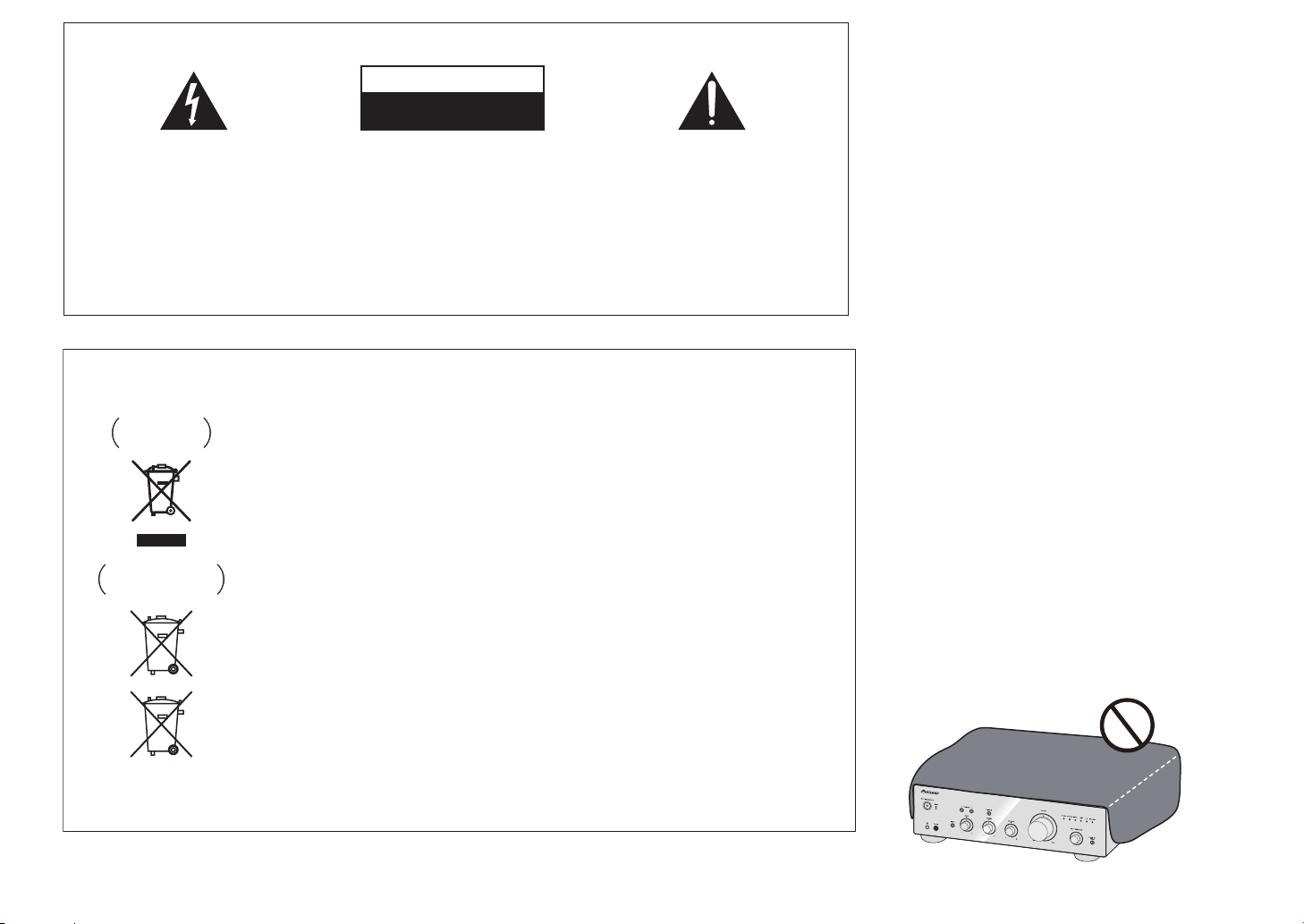
WICHTIG
CAUTION
RISK OF ELECTRIC SHOCK
DO NOT OPEN
Das Blitzsymbol in einem Dreieck weist den
Benutzer darauf hin, dass eine
Berührungsgefahr mit nicht isolierten Teilen
im Geräteinneren, die eine gefährliche
Spannung führen, besteht. Die Spannung
kann so hoch sein, dass sie die Gefahr eines
elektrischen Schlages birgt.
ACHTUNG:
UM SICH NICHT DER GEFAHR EINES
ELEKTRISCHEN SCHLAGES
AUSZUSETZEN, DÜRFEN SIE NICHT DEN
DECKEL (ODER DIE RÜCKSEITE)
ENTFERNEN. IM GERÄTEINNEREN
BEFINDEN SICH KEINE VOM BENUTZER
REPARIERBAREN TEILE. ÜBERLASSEN SIE
REPARATUREN DEM QUALIFIZIERTEN
KUNDENDIENST.
Informationen für Anwender zur Sammlung und Entsorgung von Altgeräten und
gebrauchten Batterien
Symbol für
Geräte
Symbolbeispiele
für Batterien
Pb
Diese Symbole auf den Produkten, der Verpackung und/oder Begleitdokumenten
bedeuten, dass gebrauchte elektrische und elektronische Produkte und Batterien
nicht über den Haushaltsmüll entsorgt werden dürfen.
Zur richtigen Handhabung, Rückgewinnung und Wiederverwertung von Altprodukten
und gebrauchten Batterien bringen Sie diese bitte zu den gemäß der nationalen
Gesetzgebung dafür zuständigen Sammelstellen.
Mit der korrekten Entsorgung dieser Produkte und Batterien helfen Sie dabei,
wertvolle Ressourcen zu schonen und vermeiden mögliche negative Auswirkungen
auf die Gesundheit und die Umwelt, die durch eine unsachgemäße Behandlung des
Abfalls entstehen könnten.
Weitere Informationen zur Sammlung und Wiederverwertung von Altprodukten und
Batterien erhalten Sie von Ihrer örtlichen Gemeindeverwaltung, Ihrem Müllentsorger
oder dem Verkaufsort, an dem Sie die Waren erworben haben.
Diese Symbole gelten ausschließlich in der Europäischen Union.
Für Länder außerhalb der Europäischen Union:
Wenn Sie diese Gegenstände entsorgen wollen, wenden Sie sich bitte an Ihre
lokalen Behörden oder Händler und fragen Sie dort nach der korrekten
Entsorungsweise.
Ein Ausrufezeichen in einem Dreieck weist
den Benutzer auf wichtige Bedienungs- und
Wartungsanweisungen in den Dokumenten
hin, die dem Gerät beiliegen.
D3-4-2-1-1_A1_De
WARNUNG
Dieses Gerät ist nicht wasserdicht. Zur Vermeidung der
Gefahr von Brand und Stromschlag keine Behälter mit
Flüssigkeiten (z.B. Blumenvasen und -töpfe) in die
Nähe des Gerätes bringen und dieses vor Tropfwasser,
Spritzwasser, Regen und Nässe schützen.
D3-4-2-1-3_A1_De
WARNUNG
Vor dem erstmaligen Anschluss des Gerätes an das
Stromnetz bitte den folgenden Hinweis sorgfältig
beachten.
Die Netzspannung ist je nach Land verschieden.
Vor der Inbetriebnahme des Gerätes sicherstellen,
dass die örtliche Netzspannung mit der auf dem
Typenschild an der Rückwand des Gerätes
angegebenen Nennspannung (z.B. 230 V oder 120
V) übereinstimmt.
D3-4-2-1-4*_A1_De
VORSICHTSHINWEIS ZUR BELÜFTUNG
Bei der Aufstellung dieses Gerätes muss für einen
ausreichenden Freiraum gesorgt werden, um eine
einwandfreie Wärmeabfuhr zu gewährleisten
(mindestens 30 cm oberhalb des Gerätes, 10 cm hinter
dem Gerät und jeweils 10 cm an der Seite des Gerätes).
WARNUNG
Im Gerätegehäuse sind Ventilationsschlitze und andere
Öffnungen vorgesehen, die dazu dienen, eine
Überhitzung des Gerätes zu verhindern und einen
zuverlässigen Betrieb zu gewährleisten. Um
Brandgefahr auszuschließen, dürfen diese Öffnungen
auf keinen Fall blockiert oder mit Gegenständen (z.B.
Zeitungen, Tischdecken und Gardinen) abgedeckt
werden, und das Gerät darf beim Betrieb nicht auf
einem dicken Teppich oder Bett aufgestellt sein.
D3-4-2-1-7b*_A1_De
K058a_A1_De
Betriebsumgebung
Betriebstemperatur und Betriebsluftfeuchtigkeit:
+5 °C bis +35 °C, 85 % rel. Feuchte max.
(Ventilationsschlitze nicht blockiert)
Eine Aufstellung dieses Gerät an einem unzureichend
belüfteten, sehr feuchten oder heißen Ort ist zu
vermeiden, und das Gerät darf weder direkter
Sonneneinstrahlung noch starken Kunstlichtquellen
ausgesetzt werden.
Falls der Netzstecker des Netzkabels dieses Gerätes
nicht in die Zusatzsteckdose einer anderen
Komponente passt, muss er gegen einen Netzstecker
der geeigneten Ausführung ausgewechselt werden.
Ein derartiger Austausch des Netzsteckers muss vom
Kundendienstpersonal vorgenommen werden. Wenn
der vom Netzkabel abgeschnittene ursprüngliche
Netzstecker in eine Netzsteckdose eingesteckt wird,
besteht akute Stromschlaggefahr! Daher ist
unbedingt dafür zu sorgen, dass der abgeschnittene
Netzstecker sofort vorschriftsmäßig entsorgt wird.
Vor einem längeren Nichtgebrauch des Gerätes,
beispielsweise während des Urlaubs, sollte der
Netzstecker aus der Netzsteckdose gezogen werden,
um das Gerät vollständig vom Netz zu trennen.
ACHTUNG
Der /I STANDBY/ON-Schalter dieses Gerätes
trennt das Gerät nicht vollständig vom Stromnetz. Um
das Gerät vollständig vom Netz zu trennen, muss der
Netzstecker aus der Netzsteckdose gezogen werden.
Daher sollte das Gerät so aufgestellt werden, dass
stets ein unbehinderter Zugang zur Netzsteckdose
gewährleistet ist, damit der Netzstecker in einer
Notsituation sofort abgezogen werden kann. Um
Brandgefahr auszuschließen, sollte der Netzstecker
vor einem längeren Nichtgebrauch des Gerätes,
beispielsweise während des Urlaubs, grundsätzlich
von der Netzsteckdose getrennt werden.
D3-4-2-1-7c*_A1_De
D3-4-2-2-1a_A1_De
D3-4-2-2-2a*_A1_De
Dieses Gerät ist für den Heimgebrauch vorgesehen.
Falls bei Einsatz zu einem anderem Zweck (z.B.
Langzeitgebrauch zu gewerblichen Zwecken in einem
Restaurant oder Betrieb in einem Fahrzeug bzw.
Schiff) eine Funktionsstörung auftritt, die eine
Reparatur des Gerätes erforderlich macht, werden
die Reparaturkosten dem Kunden selbst dann in
Rechnung gestellt, wenn die Garantiefrist noch nicht
abgelaufen ist.
K041_A1_De
VORSICHT MIT DEM NETZKABEL
Fassen Sie das Netzkabel immer am Stecker. Ziehen Sie
nicht am Kabel selbst, und fassen Sie das Netzkabel
niemals mit nassen Händen an, da dies einen
Kurzschluss oder elektrischen Schlag verursachen kann.
Stellen Sie nicht das Gerät, Möbelstücke o.ä. auf das
Netzkabel; sehen Sie auch zu, dass es nicht eingeklemmt
wird. Machen Sie niemals einen Knoten in das Netzkabel,
und binden Sie es nicht mit anderen Kabeln. Das
Netzkabel sollte so gelegt werden, dass niemand darauf
tritt. Ein beschädigtes Netzkabel kann einen Brand oder
elektrischen Schlag verursachen. Prüfen Sie das
Netzkabel von Zeit zu Zeit. Sollte es beschädigt sein,
wenden Sie sich an Ihre nächste autorisierte
PIONEER-Kundendienststelle oder Ihren Händler, um
es zu ersetzen.
S002*_A1_De
WARNUNG
Keine Quellen offener Flammen (z.B. eine brennende
Kerze) auf dieses Gerät stellen.
(nur A-30)
AUHTUNG:
HEISSE OBERFLÄCHE. NICHT BERÜHREN.
Die Oberabdeckung über dem internen
Kühlkörper kann bei längerem Gebrauch
dieses Produkts sehr heiß werden.
D3-4-2-1-7a_A1_De
Vielen Dank für den Erwerb dieses
Pioneer Produkts.
Lesen Sie bitte zum korrekten Betrieb Ihres Modells die
gesamte Bedienungsanleitung durch. Bewahren Sie sie
nach dem Durchlesen zur Einsicht an einem sicheren
Ort auf
.
Inhalt
01 Bevor Sie beginnen
Prüfung des Kartoninhalts. . . . . . . . . . . . . . . . . . . 4
Batterien in die Fernbedienung einlegen
(außer A-10) . . . . . . . . . . . . . . . . . . . . . . . . . . . . . . 4
Verwendung der Fernbedienung . . . . . . . . . . . . . . .4
Aufstellung des Verstärkers. . . . . . . . . . . . . . . . . .4
02 Anschlüsse
Anschließen der Kabel. . . . . . . . . . . . . . . . . . . . . .5
“Bi-wiring” (Doppelverkabelung) . . . . . . . . . . . . . .5
Lautsprecherkabel anschließen. . . . . . . . . . . . . . . 6
Audiokabel anschließen. . . . . . . . . . . . . . . . . . . . . 6
Zentrale Steuerung mit anderen Pioneer-
Komponenten (außer A-10) verwenden . . . . . . . . . 6
Anschließen. . . . . . . . . . . . . . . . . . . . . . . . . . . . . . 6
03 Bedienelemente und Anzeigen
Vorderseite . . . . . . . . . . . . . . . . . . . . . . . . . . . . . . 7
Rückwand . . . . . . . . . . . . . . . . . . . . . . . . . . . . . . .8
Fernbedienung (außer A-10) . . . . . . . . . . . . . . . . .9
04 Bedienung
Wiedergabe . . . . . . . . . . . . . . . . . . . . . . . . . . . . . 10
Bereitschaftsmodus einstellen . . . . . . . . . . . . . . .10
Wenn das Gerät als Verstärker
eingesetzt wird (nur A-30) . . . . . . . . . . . . . . . . . . .10
Vornahme eine Audioaufnahme . . . . . . . . . . . . . 11
Automatisch in den Bereitschaftsmodus
wechseln (Auto-Abschaltung) . . . . . . . . . . . . . . .11
Alle Einstellungen auf die Werkseinstellungen
rücksetzen . . . . . . . . . . . . . . . . . . . . . . . . . . . . . 11
05 Zusätzliche Informationen
Fehlerbehandlung . . . . . . . . . . . . . . . . . . . . . . . . 12
Reinigung des Geräts . . . . . . . . . . . . . . . . . . . . . 12
Technische Daten . . . . . . . . . . . . . . . . . . . . . . . .13
3
 Loading...