

Pioneer A-209 Service manual
VOLUME
LOUDNESS DIRECT
MIN MAX
TAPE 1
TUNER
CD
BALANCE
L
R
TAPE 2
LINE
PHONO
/CD-R/MD
MONITOR
INPUT SELECTOR
TAPE 2
MONITOR
—
A SPEAKERS B
STEREO AMPLIFIER
z¿<?/B
Î
POWER
OFF ON
_
PHONES
Direct Energy MOS
BASS
TREBLE
–
–
+
+
STEREO AMPLIFIER
A-209R
A-209
THIS MANUAL IS APPLICABLE TO THE FOLLOWING MODEL(S) AND TYPE(S).
Type
A-209R A-209 the following method.
Model
Power Requirement
MYXJ – AC220-230V –––––
MVXJ – AC220-230V –––––
MLXJ – AC220-230V –––––
SBDXJ – AC110V/120-127V/220V/240V With the voltage selector
The voltage can be converted by
ORDER NO.
RRV2283
CONTENTS
1. SAFETY INFORMATION
2. EXPLODED VIEWS AND PARTS LIST
3. BLOCK DIAGRAM AND SCHEMATIC DIAGRAM
4. PCB CONNECTION DIAGRAM
5. PCB PARTS LIST
6. ADJUSTMENT
...............................................
....................................................
PIONEER CORPORATION 4-1, Meguro 1-chome, Meguro-ku, Tokyo 153-8654, Japan
PIONEER ELECTRONICS SERVICE, INC. P.O. Box 1760, Long Beach, CA 90801-1760, U.S.A.
PIONEER EUROPE N.V. Haven 1087, Keetberglaan 1, 9120 Melsele, Belgium
PIONEER ELECTRONICS ASIACENTRE PTE. LTD. 253 Alexandra Road, #04-01, Singapore 159936
c
PIONEER CORPORATION 2000
......................................
...............
.....
.........................
16
24
27
2
3
6
7. GENERAL INFORMATION
7.1 DISASSEMBLY
7.2 IC
..................................................................
8. PANEL FACILITIES AND SPECIFICATIONS
................................
............................................
.......
T – ZZK APR. 2000 Printed in Japan
28
28
29
30
A-209R, A-209
1. SAFETY INFORMATION
This service manual is intended for qualified service technicians ; it is not meant for the casual do-ityourselfer. Qualified technicians have the necessary test equipment and tools, and have been trained
to properly and safely repair complex products such as those covered by this manual.
Improperly performed repairs can adversely affect the safety and reliability of the product and may
void the warranty. If you are not qualified to perform the repair of this product properly and safely, you
should not risk trying to do so and refer the repair to a qualified service technician.
WARNING
This product contains lead in solder and certain electrical parts contain chemicals which are known to the state of California to cause
cancer, birth defects or other reproductive harm.
NOTICE
(FOR CANADIAN MODEL ONLY)
Fuse symbols (fast operating fuse) and/or (slow operating fuse) on PCB indicate that replacement parts must
be of identical designation.
REMARQUE
(POUR MODÈLE CANADIEN SEULEMENT)
Les symboles de fusible (fusible de type rapide) et/ou (fusible de type lent) sur CCI indiquent que les pièces
de remplacement doivent avoir la même désignation.
Health & Safety Code Section 25249.6 – Proposition 65
(FOR USA MODEL ONLY)
1. SAFETY PRECAUTIONS
The following check should be performed for the
continued protection of the customer and service
technician.
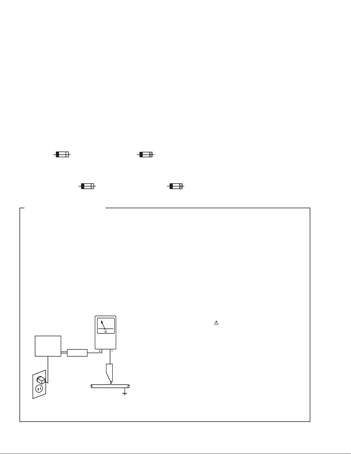
LEAKAGE CURRENT CHECK
Measure leakage current to a known earth ground (water
pipe, conduit, etc.) by connecting a leakage current tester
such as Simpson Model 229-2 or equivalent between the
earth ground and all exposed metal parts of the appliance
(input/output terminals, screwheads, metal overlays, control
shaft, etc.). Plug the AC line cord of the appliance directly
into a 120V AC 60Hz outlet and turn the AC power switch
on. Any current measured must not exceed 0.5mA.
Reading should
not be above
0.5mA
Earth
ground
Device
under
test
Also test with
plug reversed
(Using AC adapter
plug as required)
Test all
exposed metal
surfaces
Leakage
current
tester
ANY MEASUREMENTS NOT WITHIN THE LIMITS
OUTLINED ABOVE ARE INDICATIVE OF A POTENTIAL
SHOCK HAZARD AND MUST BE CORRECTED BEFORE
RETURNING THE APPLIANCE TO THE CUSTOMER.
2. PRODUCT SAFETY NOTICE
Many electrical and mechanical parts in the appliance
have special safety related characteristics. These are
often not evident from visual inspection nor the protection
afforded by them necessarily can be obtained by using
replacement components rated for voltage, wattage, etc.
Replacement parts which have these special safety
characteristics are identified in this Service Manual.
Electrical components having such features are identified
by marking with a
in this Service Manual.
The use of a substitute replacement component which does
not have the same safety characteristics as the PIONEER
recommended replacement one, shown in the parts list in
this Service Manual, may create shock, fire, or other hazards.
Product Safety is continuously under review and new
instructions are issued from time to time. For the latest
information, always consult the current PIONEER Service
Manual. A subscription to, or additional copies of, PIONEER
Service Manual may be obtained at a nominal charge from
PIONEER.
on the schematics and on the parts list
AC Leakage Test
2
A-209R, A-209
2. EXPLODED VIEWS AND PARTS LIST
NOTES:• Parts marked by "NSP" are generally unavailable because they are not in our Master Spare Parts List.
2.1 PACKING
MVXJ type Only
19
The mark found on some component parts indicates the importance of the safety factor of the part.
•
Therefore, when replacing, be sure to use parts of identical designation.
Screws adjacent to mark on the product are used for disassembly.
•
(1) PACKING PARTS LIST
20
17
12
13
8
10
FRONT
16 (SBDXJ
type Only)
Except
MVXJ type
18
6
7
1 (MYXJ and
MVXJ types
Only)
9
5
15
(SBDXJ type
Only)
2 (MYXJ type
Only)
3 (MYXJ type
Only)
4 (MYXJ and
MVXJ types
Only)
14 (MLXJ and
SBDXJ types
Only)
Mark No. Description Part No.
1 Operating Instructions See Contrast table(2)
(English)
2 Operating Instructions See Contrast table(2)
(German)
3 Operating Instructions See Contrast table(2)
(French/Italian/Dutch/Swedish/Spanish/Portugese)
NSP 4 Warranty Card See Contrast table(2)
5 Remote Control Unit (CU-A019) See Contrast table(2)
6 Battery Cover See Contrast table(2)
NSP 7 Dry Cell Battery (AA/R6P) See Contrast table(2)
8 Side Pad L AHA7205
9 Side Pad R AHA7206
10 Sub Pad AHA7218
11 Packing Case See Contrast table(2)
NSP 12 Literature Bag AHG1180
13 Packing Sheet AHG7015
14 Operating Instructions See Contrast table(2)
(English/Spanish/Chinese)
15 Caution Label 220V See Contrast table(2)
16 AC Plug Adapter See Contrast table(2)
NSP 17 Air Cap See Contrast table(2)
18 Power Cord See Contrast table(2)
19 Power Cord with Fuse See Contrast table(2)
20 Fuse (T5A) See Contrast table(2)
11
(2) CONTRAST TABLE
A-209R/MYXJ, MVXJ, A-209/MLXJ and SBDXJ are constructed the same except for the following :
Part No.
Mark No. Symbol and Description A-209R A-209R A-209 A-209 Remarks
/MYXJ /MVXJ /MLXJ /SBDXJ
1 Operating Instructions (English) ARB7236 ARB7236 Not used Not used
2 Operating Instructions (German) ARC7322 Not used Not used Not used
3 Operating Instructions (French/Italian/ ARC7323 Not used Not used Not used
Dutch/Swedish/Spanish/Portuguese)
NSP 4 Warranty Card ARY7022 ARY7022 Not used Not used
5 Remote Control Unit (CU-A019) AXD7193 AXD7193 Not used Not used
6 Battery Cover AZN2249 AZN2249 Not used Not used
NSP 7 Dry Cell Battery (AA/R6P) VEM-013 VEM-013 Not used Not used
11 Packing Case AHD7869 AHD7869 AHD7870 AHD7891
14 Operating Instructions Not used Not used ARE7269 ARE7269
(English/Spanish/Chinese)
15 Caution Label 220V Not used Not used Not used ARR1003
16 AC Plug Adapter Not used Not used Not used VKX1007
NSP 17 Air Cap Not used AHG1087 Not used Not used
18 Power Cord ADG1154 Not used ADG1154 ADG1154
19 Power Cord with Fuse Not used ADG1156 Not used Not used
20 Fuse (T5A) Not used AEK1046 Not used Not used
3
A-209R, A-209
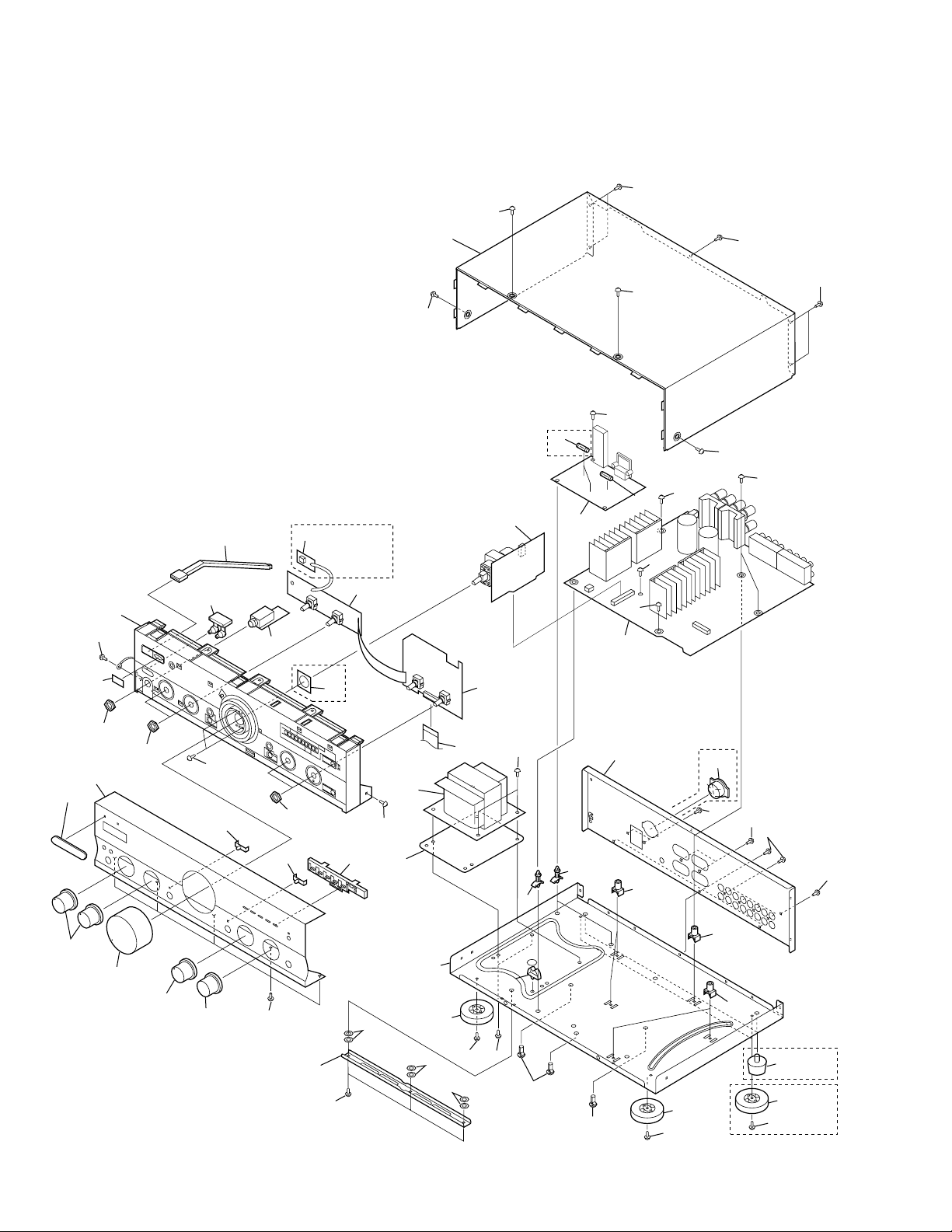
2.2 EXTERIOR
36
39
26
39
28 or 44
38
30
39
18
37
41
34
16
35
27
26
39
39
SBDXJ
Type Only
3
MYXJ,
MVXJ
Types Only
1
5
41
MYXJ,
25
MVXJ
Types Only
11
39
2
9
43
15
8
6
17
4
15
15
7
13
42
39
39
SBDXJ
Type Only
39
15
39
39
31
33
31
32
27
39
48
49
29
46
47
12
46
14
46
39
17
22
19
21
19
21
23
39
14
23
23
39
45
14
40
MLXJ,
SBDXJ
MYXJ,
MVXJ
4
A-209R, A-209
(1) EXTERIOR PARTS LIST
Mark No. Description Part No. Mark No. Description Part No.
1 FRONT L Assy See Contrast table(2)
2 FRONT R Assy See Contrast table(2)
3 OPT Assy See Contrast table(2)
4 AC PRIMARY Assy See Contrast table(2)
NSP 5 HEADPHONE Assy AWX7114
6 VOLUME Assy See Contrast table(2)
7 AF Assy See Contrast table(2)
8 Fuse (FU1) See Contrast table(2)
9 Flexible Cable (19P) ADD7032
(AF CN202-FRONT R CN601)
10 • • • • •
11 Power Transformer (T1) See Contrast table(2)
NSP 12 Chassis ANA7064
13 Rear Panel See Contrast table(2)
14 Insulator See Contrast table(2)
15 Screw (3 × 8) ABA1018
16 Screw (3 × 8) ABA1027
17 Screw (4 × 10) ABA7047
18 Nut ABN-065
19 PCB Support AEC7006
20 • • • • •
NSP 21 PCB Holder AEC7057
NSP 22 Cord Clamp F AEC7134
23 PCB Mold AMR2533
24 • • • • •
NSP 25 Shield Plate See Contrast table(2)
26 Screw (3 × 8) PBA1096
27 LED Lens AAK2459
28 IR Filter See Contrast table(2)
29 LED Lens A AAK7537
30 Name Plate PAM1776
31 Rotary Knob A AAB7148
32 Rotary Knob B AAB7149
33 Volume Knob AAB7150
34 Speaker Button AAD7435
35 Power Joint AAD7439
36 Bonnet Case ANE7183
37 Panel Base AMB7489
38 Front Panel See Contrast table(2)
39 Screw BBZ30P080FZK
40 Screw BCZ30P060FCC
41 Nut NK90FUC
42 Voltage Selector (S2) See Contrast table(2)
43 Fuse (FU2, FU3 : 1.25A) See Contrast table(2)
44 PVC Cover See Contrast table(2)
45 Foot See Contrast table(2)
46 Spacer ABF7004
47 Transformer Plate ANG7312
NSP 48 Sub Frame ANG7313
49 Screw IBZ30P120FCC
(2) CONTRAST TABLE
A-209R/MYXJ, MVXJ, A-209/MLXJ and SBDXJ are constructed the same except for the following :
Part No.
Mark No. Symbol and Description A-209R A-209R A-209 A-209 Remarks
/MYXJ /MVXJ /MLXJ /SBDXJ
1 FRONT L Assy AWX7123 AWX7123 AWX7122 AWX7122
2 FRONT R Assy AWX7124 AWX7124 AWX7121 AWX7121
3 OPT Assy AWX7125 AWX7125 Not used Not used
4 AC PRIMARY Assy AWX7113 AWX7113 AWX7113 AWX7670
6 VOLUME Assy AWX7118 AWX7118 AWX7112 AWX7112
7 AF Assy AWX7117 AWX7117 AWX7116 AWX7116
8 Fuse (FU1 : 1.25A) REK1023 REK1023 REK1023 Not used
8 Fuse (FU1 : 6.3A) Not used Not used Not used REK1030
11 Power Transformer (AC220-230V) ATS7190 ATS7190 ATS7190 Not used
11 Power Transformer Not used Not used Not used ATS7191
(AC110V/120-127V/220V/240V)
13 Rear Panel ANC7925 ANC7925 ANC7927 ANC7928
NSP 25 Shield Plate ANK7043 ANK7043 Not used Not used
14 Insulator PNW2766 PNW2766 AMR7198 AMR7198
28 IR Filter AAK7532 AAK7532 Not used Not used
38 Front Panel AMB7710 AMB7710 AMB7711 AMB7711
42 Voltage Selector (S2) Not used Not used Not used AKX-507
43 Fuse (FU2, FU3 : 1.25A) Not used Not used Not used REK1023
44 PVC Cover Not used Not used AAK7541 AAK7541
45 Foot Not used Not used REC1263 REC1263
5
1
23
A-209R, A-209
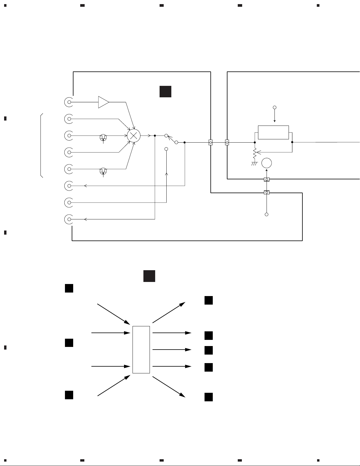
3. BLOCK DIAGRAM AND SCHEMATIC DIAGRAM
A
3.1 BLOCK DIAGRAM
4
CN101
CN102
2.8mV
PHONO
/50kΩ
TUNER
CD
200mV
/50kΩ
LINE
TAPE1
/CD-R
200mV
/1kΩ
200mV
/50kΩ
200mV
/1kΩ
/MD
REC
TAPE2
MONITOR
REC
B
IC151
RIAA
31
37dB
Q101
Q103
26
24
25
FUNCTION
27
24
24
D
AF ASSY
IC101
19
18
17
CN203
20
12 12
CN501
Q501
Q503
LOUDNESS
CN501
CN203
UP/DOWN
ON/OFF
VOLUME
M
VR501
1, 2
1, 2
Q337-Q340
F
Q331, Q327, Q328
C
D
D
FROM UNUSUAL
OUTPUT DETECTION
KEY INPUTS
S602, S603
S702–S704
E
FROM FUNCTION SEL
S601
604
G
FRONT R ASSY
23, 24,
36, 40,
µ-COM
42
IC601
32, 33
137
TO FUNCTION SW
2, 3, 438
DIRECT, LOUDNESS ON/OFF
12, 15
VOLUME UP/DOWN
30, 31
FUNC MUTE ON/OFF
17
TO PROTECTION RYSR INPUT
IC101
D
Q501–Q514
A
Q337–Q340
D
Q303
D
Q334, Q336
D
6
1234
5
678
A-209R, A-209
A
A
VOLUME ASSY
DIRECT
ON/OFF
Q505
Q507 Q509
CN50276
J37
TONE
6
AND
BALANCE
IC751
VR751
VR752
VR601
F
CN501 CN203
6
7
E
FRONT L ASSY
D
AF ASSY
DIRECT ENERGY MOS
POWER AMP
WRLC
39dB
8
8
Q303
IC301
Q309–Q330
FUNC
MUTE
PROTECTION RY
UNUSUAL
OUTPUT
DETECTION
Q331, Q327, Q328
RY401
RY402
RY403
J551
J551
1
1
B
HEADPHONE ASSY
401
SP-A
SP-B
B
H.P
JA501
TO POWER STAGE
TO µ-COM
LED
TO VOLTAGE STAGE
5
TO OP AMP
RY
+BH
–BH
+BL
–BL
+ 6
IC453
IC451
IC452
Q451
REGULATOR
Q452
6
AF ASSY
+19
–15
D452–D455
D
D451
C
C
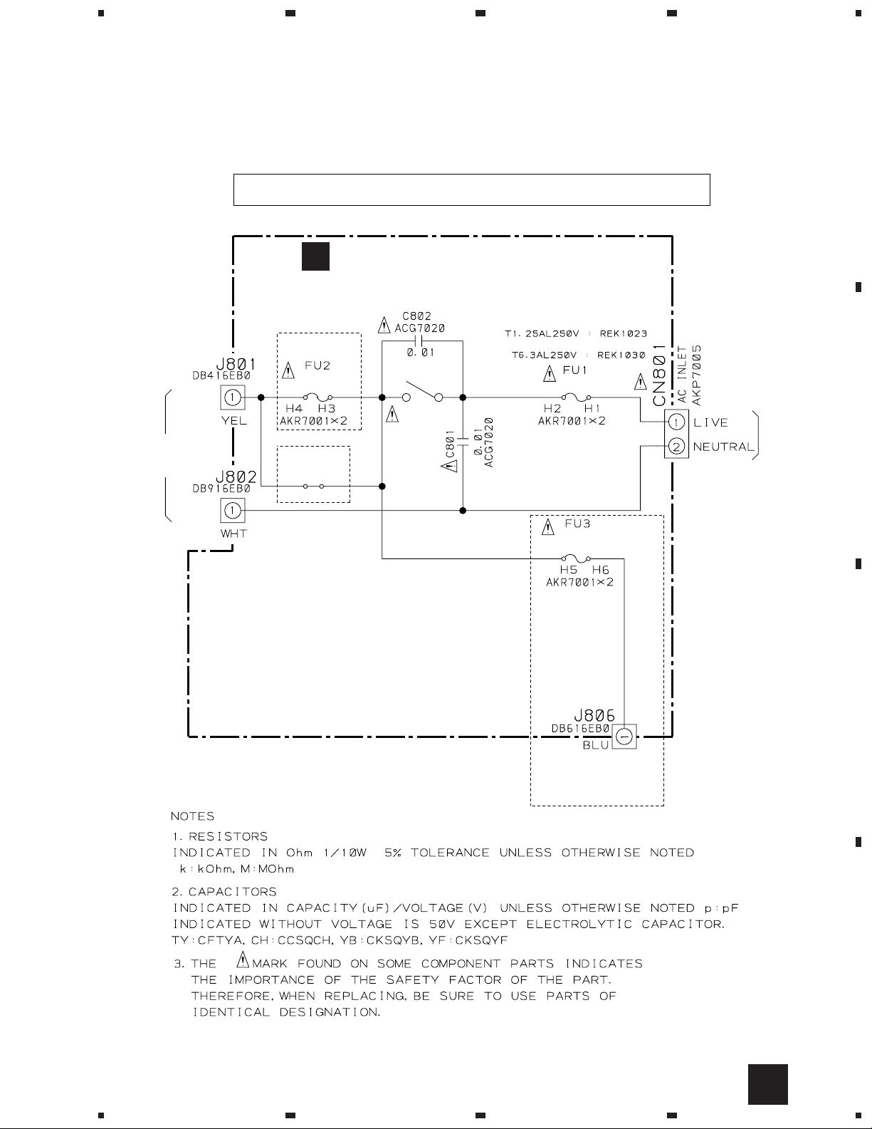
AC PRIMARY ASSY
S801 FU1T1
D
7
7
8
1
23
A-209R, A-209
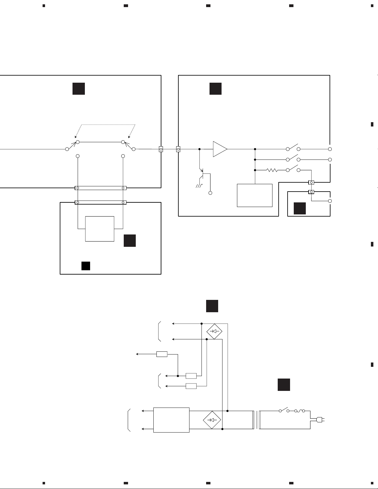
3.2 OVERALL CONNECTION DIAGRAM
A
4
B
HEADPHONE ASSY
AWX7114
B
AWX7124 (MYXJ, MVXJ)
AWX7121 (MLXJ, SBDXJ)
F
FRONT R ASSY
D
AWX7117 (MYXJ, MVXJ)
AWX7116 (MLXJ, SBDXJ)
AF ASSY
C
451
A
VOLUME ASSY
AWX7118 (MYXJ, MVXJ)
AWX7112 (MLXJ, SBDXJ)
D
8
1234
5
678
A-209R, A-209
Note : When ordering service parts, be sure to refer to "EXPLODED VIEWS and PARTS LIST" or "PCB PARTS LIST".
E
FRONT L ASSY
AWX7123 (MYXJ, MVXJ)
AWX7122 (MLXJ, SBDXJ)
A
G
OPT ASSY
AWX7125
(MYXJ, MVXJ)
POWER TRANSFORMER
ATS7190 : MYXJ, MVXJ, MLXJ
C
AC PRIMARY ASSY
AWX7113
(MYXJ, MVXJ, MLXJ)
AWX7670
(SBDXJ)
MYXJ, MVXJ,
MLXJ types
S2 : AKX-507
VOLTAGE
SELECTOR
SBDXJ type
A-209/SBDXJ
ADG1154 : MYXJ, MLXJ types
AC POWER CORD
ADG1156 : MVXJ type
ADG1154 (VKX1007) : SBDXJ type
(VKX1007)
B
C
POWER TRANSFORMER
ATS7191 : SBDXJ
5
D
9
6
7
8
1
23
A-209R, A-209
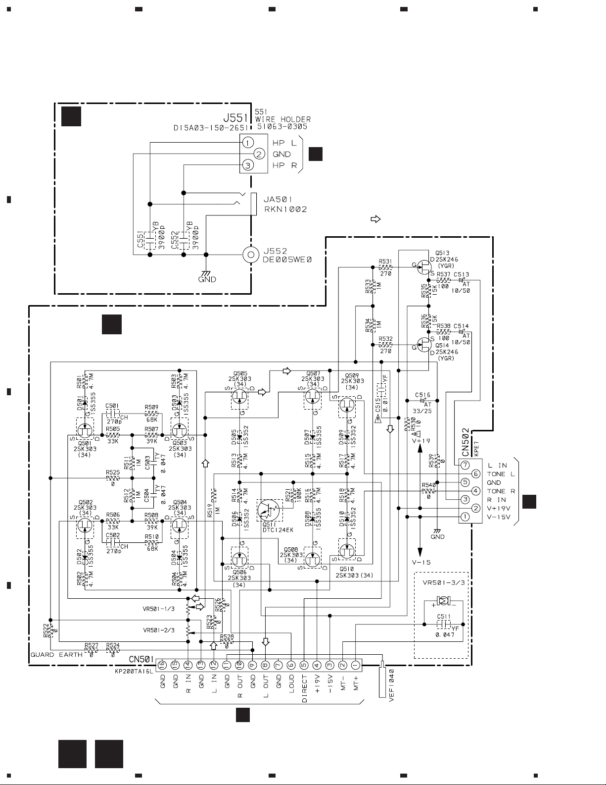
3.3 VOLUME and HEADPHONE ASSYS
A
B
HEADPHONE ASSY
AWX7114
B
D
4
J551A
: AUDIO SIGNAL ROUTE
VOLUME ASSY
A
AWX7118 (MYXJ, MVXJ)
AWX7112 (MLXJ, SBDXJ)
C
J3
E
ACX7038
VR-501 : ACX7038 (MYXJ, MVXJ)
VR-501 : ACS7035 (MLXJ, SBDXJ)
(MYXJ, MVXJ)
D
CN203
D
10
A
B
1234
1
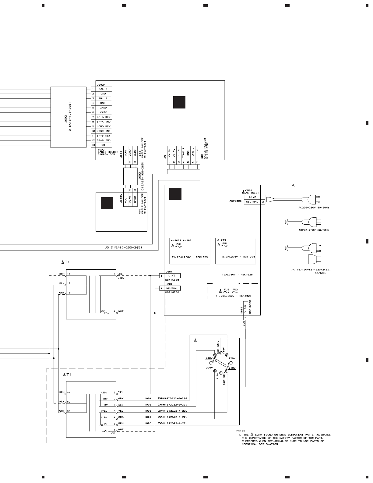
3.4 AC PRIMARY ASSY
• NOTE FOR FUSE REPLACEMENT
CAUTION -
C
SBDXJ type
234
A-209R, A-209
A
FOR CONTINUED PROTECTION AGAINST RISK OF FIRE.
REPLACE WITH SAME TYPE AND RATINGS ONLY.
AC PRIMARY ASSY
AWX7113 (MYXJ, MVXJ, MLXJ)
AWX7670 (SBDXJ)
MYXJ, MVXJ, MLXJ types
SBDXJ type
LIVE
TO POWER
TRANSFORMER
NEUTRAL
REK1023
T1.25AL250V
MYXJ,
MVXJ,
MLXJ types
POWER
S801
ASG1035
REK1023
T1.25AL250V
A-209/SBDXJ
TO S2
VOLTAGE
SELECTOR
TO
AC POWER
CORD
B
C
D
C
1
2
3
4
11
 Loading...