

Page 1

Operating Instructions
Mode d’emploi
Integrated Amplifier
Amplificateur Intégré
Page 2
IMPORTANT
CAUTION
RISK OF ELECTRIC SHOCK
DO NOT OPEN
The lightning flash with arrowhead symbol,
within an equilateral triangle, is intended to
alert the user to the presence of uninsulated
“dangerous voltage” within the product’s
enclosure that may be of sufficient
magnitude to constitute a risk of electric
shock to persons.
WARNING
This equipment is not waterproof. To prevent a fire or
shock hazard, do not place any container filled with
liquid near this equipment (such as a vase or flower
pot) or expose it to dripping, splashing, rain or
moisture.
WARNING
Before plugging in for the first time, read the following
section carefully.
The voltage of the available power supply differs
according to country or region. Be sure that the
power supply voltage of the area where this unit
will be used meets the required voltage (e.g., 230 V
or 120 V) written on the rear panel.
CAUTION:
TO PREVENT THE RISK OF ELECTRIC
SHOCK, DO NOT REMOVE COVER (OR
BACK). NO USER-SERVICEABLE PARTS
INSIDE. REFER SERVICING TO QUALIFIED
SERVICE PERSONNEL.
D3-4-2-1-3_A1_En
D3-4-2-1-4*_A1_En
The exclamation point within an equilateral
triangle is intended to alert the user to the
presence of important operating and
maintenance (servicing) instructions in the
literature accompanying the appliance.
D3-4-2-1-1_A1_En
WARNING
To prevent a fire hazard, do not place any naked flame
sources (such as a lighted candle) on the equipment.
D3-4-2-1-7a_A1_En
VENTILATION CAUTION
When installing this unit, make sure to leave space
around the unit for ventilation to improve heat radiation
(at least 30 cm at top, 10 cm at rear, and 10 cm at each
side).
WARNING
Slots and openings in the cabinet are provided for
ventilation to ensure reliable operation of the product,
and to protect it from overheating. To prevent fire
hazard, the openings should never be blocked or
covered with items (such as newspapers, table-cloths,
curtains) or by operating the equipment on thick carpet
or a bed.
D3-4-2-1-7b*_A1_En
Operating Environment
Operating environment temperature and humidity:
+5 °C to +35 °C (+41 °F to +95 °F); less than 85 %RH
(cooling vents not blocked)
Do not install this unit in a poorly ventilated area, or in
locations exposed to high humidity or direct sunlight (or
strong artificial light)
D3-4-2-1-7c*_A1_En
If the AC plug of this unit does not match the AC
outlet you want to use, the plug must be removed
and appropriate one fitted. Replacement and
mounting of an AC plug on the power supply cord of
this unit should be performed only by qualified
service personnel. If connected to an AC outlet, the
cut-off plug can cause severe electrical shock. Make
sure it is properly disposed of after removal.
The equipment should be disconnected by removing
the mains plug from the wall socket when left unused
for a long period of time (for example, when on
vacation).
D3-4-2-2-1a_A1_En
CAUTION
The /I STANDBY/ON switch on this unit will not
completely shut off all power from the AC outlet.
Since the power cord serves as the main disconnect
device for the unit, you will need to unplug it from the
AC outlet to shut down all power. Therefore, make
sure the unit has been installed so that the power
cord can be easily unplugged from the AC outlet in
case of an accident. To avoid fire hazard, the power
cord should also be unplugged from the AC outlet
when left unused for a long period of time (for
example, when on vacation).
D3-4-2-2-2a*_A1_En
Page 3
This product is for general household purposes. Any
failure due to use for other than household purposes
(such as long-term use for business purposes in a
restaurant or use in a car or ship) and which requires
repair will be charged for even during the warranty
period.
K041_A1_En
POWER-CORD CAUTION
Handle the power cord by the plug. Do not pull out the
plug by tugging the cord and never touch the power
cord when your hands are wet as this could cause a
short circuit or electric shock. Do not place the unit, a
piece of furniture, etc., on the power cord, or pinch the
cord. Never make a knot in the cord or tie it with other
cords. The power cords should be routed such that they
are not likely to be stepped on. A damaged power cord
can cause a fire or give you an electrical shock. Check
the power cord once in a while. When you find it
damaged, ask your nearest PIONEER authorized
service center or your dealer for a replacement.
S002*_A1_En
The Safety of Your Ears is in Your Hands
Get the most out of your equipment by playing it at a
safe level – a level that lets the sound come through
clearly without annoying blaring or distortion and, most
importantly, without affecting your sensitive hearing.
Sound can be deceiving. Over time, your hearing
“comfort level” adapts to higher volumes of sound, so
what sounds “normal” can actually be loud and
harmful to your hearing. Guard against this by setting
your equipment at a safe level BEFORE your hearing
adapts.
ESTABLISH A SAFE LEVEL:
• Set your volume control at a low setting.
• Slowly increase the sound until you can hear it
comfortably and clearly, without distortion.
• Once you have established a comfortable sound
level, set the dial and leave it there.
BE SURE TO OBSERVE THE FOLLOWING
GUIDELINES:
• Do not turn up the volume so high that you can’t
hear what’s around you.
• Use caution or temporarily discontinue use in
potentially hazardous situations.
• Do not use headphones while operating a motorized
vehicle; the use of headphones may create a traffic
hazard and is illegal in many areas.
S001a_A1_En
This product contains mercury. Disposal of this
material may be regulated due to environmental
considerations. For disposal or recycling information,
please contact your local authorities or the Electronics
Industries Alliance : www.eiae.org.
K057_A1_En
IMPORTANT NOTICE
THE MODEL NUMBER AND SERIAL NUMBER OF
THIS EQUIPMENT ARE ON THE REAR OR BOTTOM.
RECORD THESE NUMBERS ON YOUR ENCLOSED
WARRANTY CARD AND KEEP IN A SAFE PLACE
FOR FUTURE REFERENCE.
D36-AP9-1_A1_En
Information to User
Alterations or modifications carried out without
appropriate authorization may invalidate the user’s
right to operate the equipment.
D8-10-2_A1_En
WARNING: Handling the cord on this product or
cords associated with accessories sold with the
product may expose you to chemicals listed on
proposition 65 known to the State of California and
other governmental entities to cause cancer and
birth defect or other reproductive harm.
D36-P5_B1_En
Caution
To prevent fire hazard, the Class 1 Wiring Cable
should be used for connection with speaker, and
should be routed away from hazards to avoid damage
to the insulation of the cable.
D3-7-13-67*_A1_En
CAUTION
This product satisfies FCC regulations when shielded
cables and connectors are used to connect the unit
to other equipment. To prevent electromagnetic
interference with electric appliances such as radios
and televisions, use shielded cables and connectors
for connections.
D8-10-3a_A1_En
FEDERAL COMMUNICATIONS COMMISSION DECLARATION OF CONFORMITY
This device complies with part 15 of the FCC Rules. Operation is subject to the following two conditions: (1) This
device may not cause harmful interference, and (2) this device must accept any interference received, including
interference that may cause undesired operation.
Product Name: Integrated Amplifier
Model Number: A-20
Responsible Party Name: PIONEER ELECTRONICS (USA) INC.
SERVICE SUPPORT DIVISION
Address: 1925 E. DOMINGUEZ ST. LONG BEACH, CA 90810-1003, U.S.A.
Phone: 1-800-421-1404
URL: http://www.pioneerelectronics.com
D8-10-4*_C1_En
This Class B digital apparatus complies with
Canadian ICES-003.
D8-10-1-3_A1_En
Page 4
11)
Read these instructions.
1)
Keep these instructions.
2)
Heed all warnings.
3)
Follow all instructions.
4)
Do not use this apparatus near water.
5)
Clean only with dry cloth.
6)
Do not block any ventilation openings. Install in
7)
Only use attachments/accessories specified by
the manufacturer.
12)
Use only with the cart, stand, tripod, bracket, or
table specified by the manufacturer, or sold with
the apparatus. When a cart is used, use caution
when moving the cart/apparatus combination to
avoid injury from tip-over.
accordance with the manufacturer’s
instructions.
Do not install near any heat sources such as
8)
radiators, heat registers, stoves, or other
apparatus (including amplifiers) that produce
heat.
Do not defeat the safety purpose of the polarized
9)
or grounding-type plug. A polarized plug has two
blades with one wider than the other. A
grounding type plug has two blades and a third
grounding prong. The wide blade or the third
prong are provided for your safety. If the provided
plug does not fit into your outlet, consult an
electrician for replacement of the obsolete outlet.
Protect the power cord from being walked on or
10)
pinched particularly at plugs, convenience
13)
Unplug this apparatus during lightning storms
or when unused for long periods of time.
14)
Refer all servicing to qualified service personnel.
Servicing is required when the apparatus has
been damaged in any way, such as power-supply
cord or plug is damaged, liquid has been spilled
or objects have fallen into the apparatus, the
apparatus has been exposed to rain or moisture,
does not operate normally, or has been dropped.
receptacles, and the point where they exit from
the apparatus.
D3-7-13-69_En
NOTE:
This equipment has been tested and found to comply with the limits for a Class B digital device, pursuant to Part 15
of the FCC Rules. These limits are designed to provide reasonable protection against harmful interference in a
residential installation. This equipment generates, uses, and can radiate radio frequency energy and, if not installed
and used in accordance with the instructions, may cause harmful interference to radio communications. However,
there is no guarantee that interference will not occur in a particular installation. If this equipment does cause
harmful interference to radio or television reception, which can be determined by turning the equipment off and on,
the user is encouraged to try to correct the interference by one or more of the following measures:
— Reorient or relocate the receiving antenna.
— Increase the separation between the equipment and receiver.
— Connect the equipment into an outlet on a circuit different from that to which the receiver is connected.
— Consult the dealer or an experienced radio/TV technician for help.
D8-10-1-2_A1_En
Thank you for buying this Pioneer
product.
Please read through these operating instructions so that
you will know how to operate your model properly. After
you have finished reading the instructions, put them in a
safe place for future reference.
Contents
01 Before you start
What’s in the box. . . . . . . . . . . . . . . . . . . . . . . . . .5
Loading the batteries in the remote control . . . . . .5
Using the remote control. . . . . . . . . . . . . . . . . . . . .5
Installing the amplifier . . . . . . . . . . . . . . . . . . . . . . 5
02 Connecting up
Making cable connections. . . . . . . . . . . . . . . . . . .6
About “Bi-wiring” . . . . . . . . . . . . . . . . . . . . . . . . . .6
Connecting speaker cables . . . . . . . . . . . . . . . . . . 7
Connecting audio cables . . . . . . . . . . . . . . . . . . . .7
Using centralized control with other Pioneer
components. . . . . . . . . . . . . . . . . . . . . . . . . . . . . . 7
Plugging in . . . . . . . . . . . . . . . . . . . . . . . . . . . . . .7
03 Controls and displays
Front panel. . . . . . . . . . . . . . . . . . . . . . . . . . . . . . .8
Rear panel . . . . . . . . . . . . . . . . . . . . . . . . . . . . . . . 9
Remote control . . . . . . . . . . . . . . . . . . . . . . . . . .10
04 Operation
Playback . . . . . . . . . . . . . . . . . . . . . . . . . . . . . . .11
Set the power to Standby. . . . . . . . . . . . . . . . . . . .11
Making an audio recording . . . . . . . . . . . . . . . . .12
To set for automatic standby status
(Auto Power Down) . . . . . . . . . . . . . . . . . . . . . . .12
Restoring all the settings to the factory default
settings . . . . . . . . . . . . . . . . . . . . . . . . . . . . . . . . 12
05 Additional information
Troubleshooting. . . . . . . . . . . . . . . . . . . . . . . . . . 13
Cleaning the unit . . . . . . . . . . . . . . . . . . . . . . . . .13
Specifications . . . . . . . . . . . . . . . . . . . . . . . . . . .14
4
Page 5
Before you start 01
7 m
30 °
30 °
Chapter 1:
Before you start
What’s in the box
Please confirm that the following accessories are in the
box when you open it.
• Remote control
• AAA/IEC R03 dry cell batteries x2
• Operating instructions (This document)
Note
• Illustrations featured in the Operating Instructions
may have been modified or simplified for ease of
explanation, and may therefore differ from the
actual product appearance.
Loading the batteries in the remote
control
1 Open the rear lid.
2 Insert the new batteries, matching the
polarities as indicated inside the case.
3 Close the rear lid.
The batteries included with the unit have been provided
to allow you check product operation and may not last
long. We recommend using alkaline batteries that have
a longer life.
WARNING
• Do not use or store batteries in direct sunlight or
other excessively hot place, such as inside a car or
near a heater. This can cause batteries to leak,
overheat, explode or catch fire. It can also reduce
the life or performance of batteries.
Caution
Incorrect use of batteries may result in such hazards as
leakage and bursting. Observe the following
precautions:
• When inserting the batteries, make sure not to
damage the springs on the battery’s terminals.
• Do not use any batteries other than the ones
specified. Also, do not use a new battery together
with an old one.
• When loading the batteries into the remote control,
set them in the proper direction, as indicated by the
polarity marks ( and ).
• Do not heat batteries, disassemble them, or throw
them into flames or water.
• Batteries may have different voltages, even if they
are the same size and shape. Do not use different
types of batteries together.
• To prevent leakage of battery fluid, remove the
batteries if you do not plan to use the remote
control for a long period of time (1 month or more).
If the fluid should leak, wipe it carefully off the
inside of the case, then insert new batteries. If a
battery should leak and the fluid should get on your
skin, flush it off with large quantities of water.
• When disposing of used batteries, please comply
with governmental regulations or environmental
public institution’s rules that apply in your country/
area.
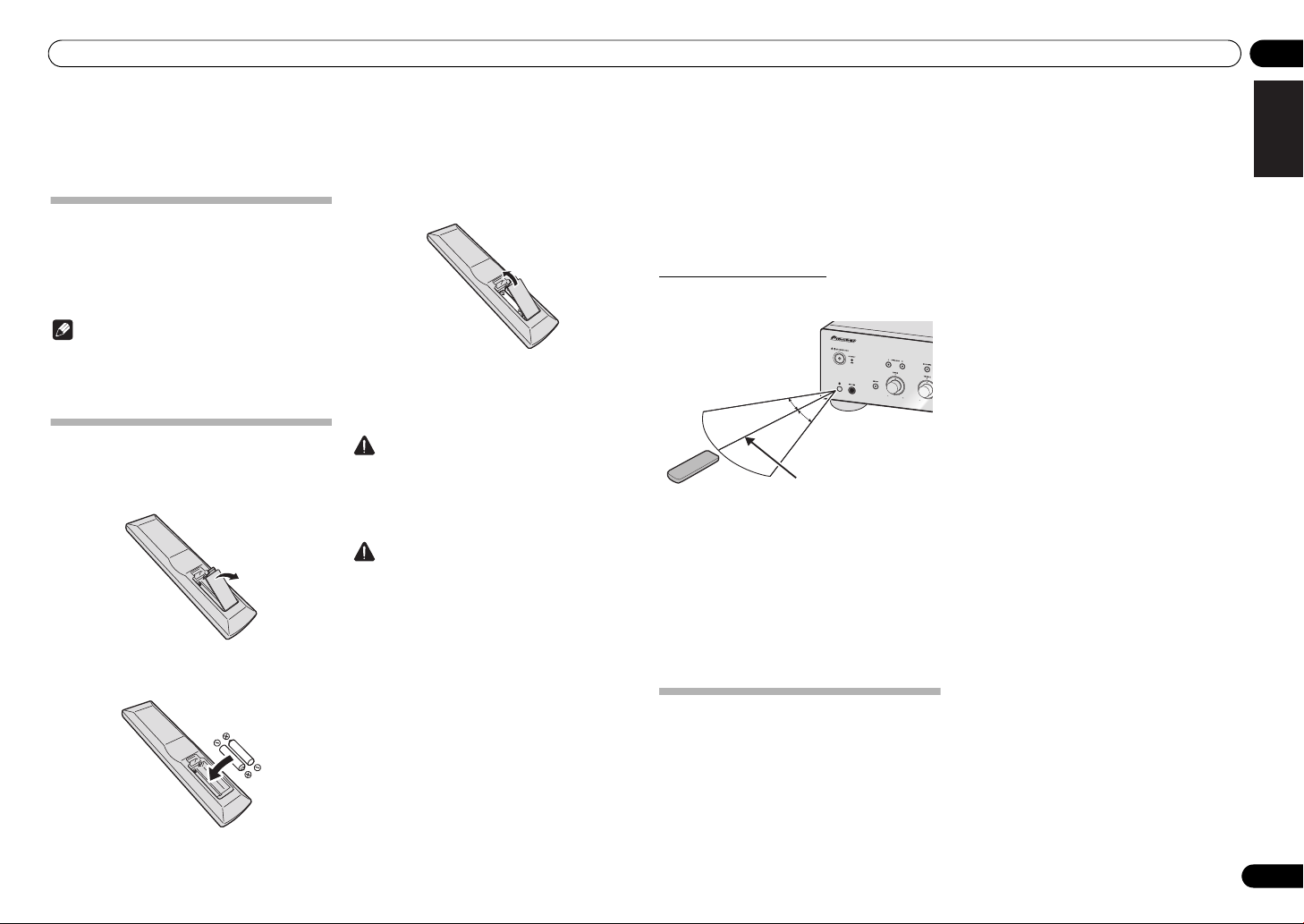
Using the remote control
The remote has a range of about 7 m at an angle of about
30º from the remote sensor.
Keep in mind the following when using the remote
control:
• Make sure that there are no obstacles between the
remote and the remote sensor on the unit.
• Remote operation may become unreliable if strong
sunlight or fluorescent light is shining on the unit’s
remote sensor.
• Remote controllers for different devices can
interfere with each other. Avoid using remotes for
other equipment located close to this unit.
• Replace the batteries when you notice a fall off in
the operating range of the remote.
Installing the amplifier
When installing this unit, make sure to put it on a level
and stable surface.
• Don’t install it on the following places:
– on a color TV (the screen may distort)
– near a cassette deck (or close to a device that
gives off a magnetic field). This may interfere with
the sound.
– in direct sunlight
– in damp or wet areas
– in extremely hot or cold areas
– in places where there is vibration or other
movement
– in places that are very dusty
– in places that have hot fumes or oils (such as a
kitchen)
• Do not mount the unit on a sofa or other object or
material with absorbent qualities, since sound
quality may be adversely affected.
English
DeutschFrançais
Italiano Español Русский
Nederlands
5
En
Page 6
02 Connecting up
REC
R
L
OUTPUT
R
L
PLAY
RL
AUDIO
OUTPUT
LRLRL
R
L
R
LRL
R
L
R
L
R
L
R
LRL
R
L
R
L
R
MENU
iPod
Music>
Extras>
Settings>
Shuffle Songs
Backlight
SACD/CD player
Network audio player
Speaker system B
Speaker system A
Turntable
Tuner
iPod dock, etc
CD recorder or
tape deck
Right
Left
Right
Left
Power cord
This unit’s rear panel
Speaker system
Left
Speaker system
Right
This unit’s
rear panel
Remove the shorting
bar between the +
and – terminals.
Chapter 2:
Connecting up
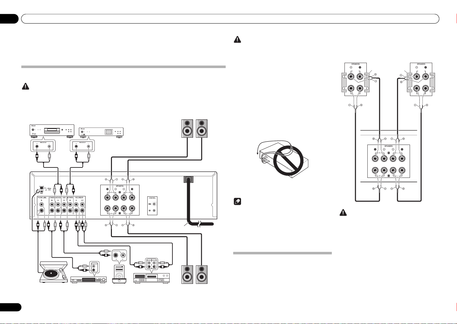
Making cable connections
Caution
• Before making or changing the connections, switch off the power and disconnect the power cord from the AC
outlet.
• Connect the power cord after all the connections between devices have been completed.
Caution
•The SIGNAL GND terminal is provided to reduce
noise when connecting the unit to components
such as an analog turntable.
• Do not connect the PHONO (MM) terminals to any
component other than a turntable; also, do not
connect to a turntable equipped with built-in
equalizer. An excessively high sound output may be
produced, resulting in damage to your speakers or
other devices.
• The unit’s PHONO (MM) terminals are designed to
be used with turntables equipped with MM
(moving-magnet) type cartridges. Turntables
equipped with MC (moving-coil) cartridges cannot
be used.
• Make sure not to bend the cables over the top of
this unit (as shown in the illustration). If this
happens, the magnetic field produced by the
transformers in this unit may cause a humming
noise from the speakers.
• If your turntable has a grounding wire, secure it to
the ground terminal on this amplifier.
Note
• When connecting a tape cassette deck, playback
noise may be heard, depending on the installation
location. This noise is caused by leakage flux from
the amplifier’s transformer. In this event, change
the installation location, or move the deck farther
from the amplifier.
• iPod is a trademark of Apple Inc., registered in the
U.S. and other countries.
About “Bi-wiring”
This unit can be used with speakers that support biwiring. Be sure to connect the high-frequency and
low-frequency connections correctly.
• During playback, be sure that both the SPEAKERS
A button and SPEAKERS B button are set to ON
(page 8).
HIGH
LOW
HIGH
LOW
Caution
• When using bi-wiring to connect speakers, avoid
adverse affects on the amplifier by being sure to
remove the HIGH and LOW short bars provided with
the speakers. For detailed information, consult the
instructions provided with the speakers.
• When using speakers with removable network
circuits, note that if the network is removed, no
effect will be produced and damage may be caused
to the speaker.
• Another method of connection is to connect the
SPEAKERS A terminals to HIGH and the SPEAKERS
B terminals to LOW (reverse that shown in the
illustration).
6
En
Page 7
Connecting up 02
10 mm
Left (white)
Right (red)
Other Pioneer
component equipped
with CONTROL IN/
OUT jacks
To other Pioneer
component
equipped with
CONTROL IN jack
Aim remote control
at the sensor on the
A-20.
A-20
remote
control
A-20
To AC outlet
Power cord
This unit’s rear panel
English
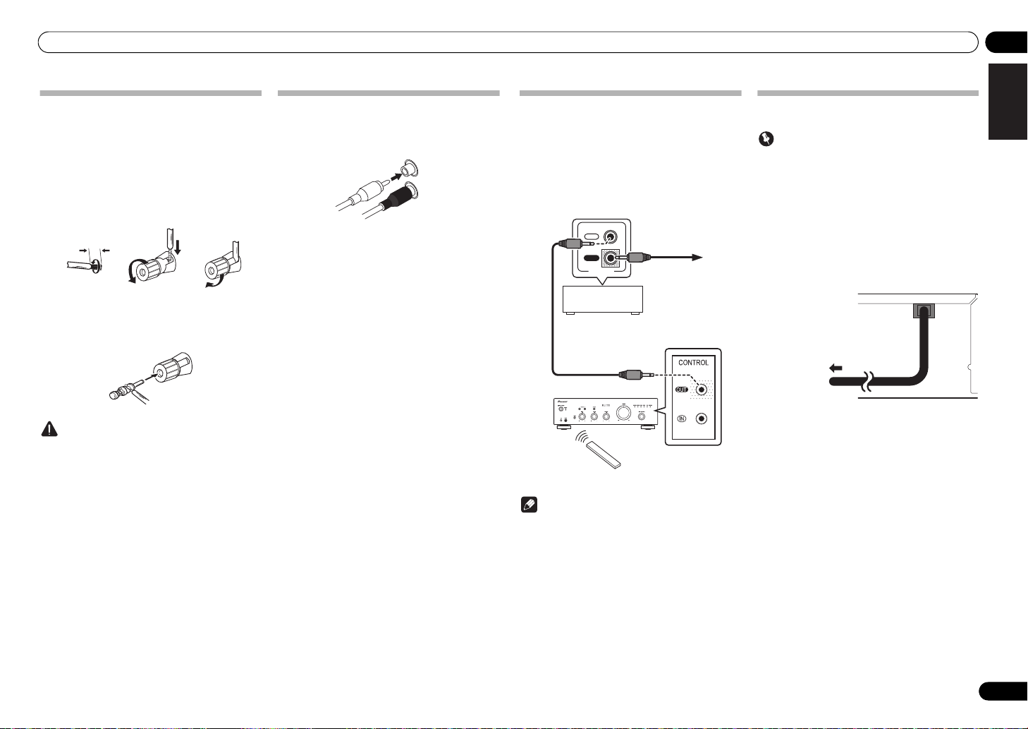
Connecting speaker cables
1 Twist the cable cores.
2 Loosen the nut on the
terminal, and insert the speaker cable into
the exposed hole in the terminal shaft.
3 Retighten the terminal nut.
123
• If you want to use speaker cables terminated with
banana plugs, screw the speaker terminal fully
shut, then plug the banana plug into the end of the
speaker terminal.
Caution
• When using only one set of speaker terminals
(SPEAKERS A or SPEAKERS B), or when utilizing
bi-wiring connections, the speaker used should
have a nominal impedance between 4 Ω and
16 Ω. When using both sets of terminals, the
connected speakers should have nominal
impedance between 8 Ω and 32 Ω. Consult the
instructions accompanying your speakers for
details regarding the impedance value.
• Make sure the positive and negative (+/–) terminals
on the amplifier match those on the speakers.
• These speaker terminals carry HAZARDOUS live
voltage. To prevent the risk of electric shock when
connecting or disconnecting the speaker cables,
disconnect the power cord before touching any
uninsulated parts.
• Make sure that all the bare speaker wire is twisted
together and inserted fully into the speaker
terminal. If any of the bare speaker wire touches the
back panel it may cause the power to cut off as a
safety measure.
SPEAKERS
Connecting audio cables
Connect the white plug to the left (L) jack, and the red
plug to the right (R) jack. Be sure to insert the plugs fully
into the jacks.
Using centralized control with other
Pioneer components
Multiple Pioneer components equipped with CONTROL
IN/OUT jacks can be connected to the A-20 unit,
allowing centralized control of the components via the
remote sensor on the A-20. This also allows remote
control of components not equipped with a remote
sensor, or installed in places where the component’s
remote sensor cannot be accessed.
IN
OUT
CONTROL
Plugging in
Important
• When going on a trip or otherwise not using the
unit for an extended period, always disconnect the
power cord from its outlet. Note that various
internal settings will not be lost even if the power
cord is disconnected from its outlet for an extended
time.
• If it is necessary to detach the power cord, first be
sure to press the
front panel of the unit so the A-20 is turned OFF.
After you’ve finished making all connections, plug the
unit into an AC outlet.
/I
STANDBY/ON button on the
DeutschFrançais
Italiano Español Русский
Nederlands
7
En
Note
• For connections use a commercially available
monaural miniplug cord (without resistor).
• When connecting the CONTROL IN/OUT jacks,
commercially available audio cords must also be
used to make analog connections. Merely
connecting the CONTROL IN/OUT jacks alone will
not allow proper system control.
• When a control cord is connected to the A-20’s
CONTROL IN jack, the unit cannot be controlled by
pointing the remote control at the A-20 (the remote
sensor is automatically disabled).
1 Plug the power cord into an AC outlet.
Page 8
03 Controls and displays
Chapter 3:
Controls and displays
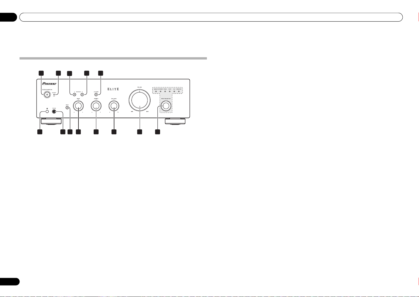
Front panel
1
2 54
3
6
1/I
STANDBY/ON
Switches the amplifier between off and on.
When power is turned on, the power indicator in the
center of the button will light.
2
STANDBY/APD
When power is set to standby, the indicator lights red.
When the Auto Power Down (APD) function is on, the
indicator lights green (page 12).
3
SPEAKERS A
Use this button to listen to the speaker system
connected to SPEAKERS A terminals.
On : The indicator lights. Sound is heard from the
speaker system. (Sound will also be produced from the
PHONES jack.)
Off : The indicator goes off. No sound is heard from the
speaker system. Set to this position when listening with
headphones.
4
SPEAKERS B
Use this button to listen to the speaker system
connected to SPEAKERS B terminals.
On : The indicator lights. Sound is heard from the
speaker system. (Sound will also be produced from the
PHONES jack.)
Off : The indicator goes off. No sound is heard from the
speaker system. Set to this position when listening with
headphones.
7
9
8
indicator
button/indicator
button/indicator
10 11 12
5
LOUDNESS
Use when listening at low volume levels.
On : The indicator lights: Boosts low and high
frequencies to give added punch to playback even at a
low volume level.
Off : The indicator goes off: Should normally be left in
this position.
• This button does not operate when the DIRECT
button is in the on position.
• When sound volume is raised, the amount of
change produced by the LOUDNESS circuit is
reduced.
13
button/indicator
6 Remote sensor
Receives the signals from the remote control (page 5).
7
PHONES
Use to connect headphones. No sound is produced
when the POWER AMP DIRECT button is ON.
8 DIRECT button/indicator
On : The indicator lights: When this button is set to ON,
sound signals are output directly, without being passed
through the various adjustment circuits (BASS, TREBLE,
BALANCE, LOUDNESS). This allows reproduction of the
signals with greater fidelity, but it disables any settings
made with the BASS, TREBLE, BALANCE or LOUDNESS
controls.
Off : The indicator goes off: The signal passes through
the various frequency adjusting circuits. When the
indicator is OFF, adjustments can be made with the
BASS, TREBLE, BALANCE, and LOUDNESS controls.
9
BASS
Use to adjust the low-frequency tone. The center position
is the flat (normal) position. When turned to the right,
low-frequency tones are emphasized; when turned to the
left, low-frequency tones are de-emphasized.
• This button does not operate when the DIRECT
button is in the on position.
10
TREBLE
Use to adjust the high-frequency tone. The center
position is the flat (normal) position. When turned to the
right, high-frequency tones are emphasized; when
turned to the left, high-frequency tones are deemphasized.
• This button does not operate when the DIRECT
button is in the on position.
11
BALANCE
Should normally be left in the center position. Adjust
balance if the sound is louder from one of the speakers.
If the right side is louder, turn toward the L (left) position
and if the left side is louder, turn toward the R (right)
position.
• This button does not operate when the DIRECT
button is in the on position.
12 VOLUME control
Use to adjust the volume level. (Also allows adjustment
of the headphone sound volume.)
jack
tone control
tone control
control
13
INPUT SELECTOR
Turn the knob clockwise or counterclockwise so that the
indicator lights for your desired input source. Turning
the knob clockwise causes the lit indicator to right.
Turning counterclockwise causes it to left. When the
remote control’s MUTE button is pressed to mute the
sound, the indicator for the input source selected with
the INPUT SELECTOR knob flashes.
knob/indicators
8
En
Page 9
Controls and displays 03
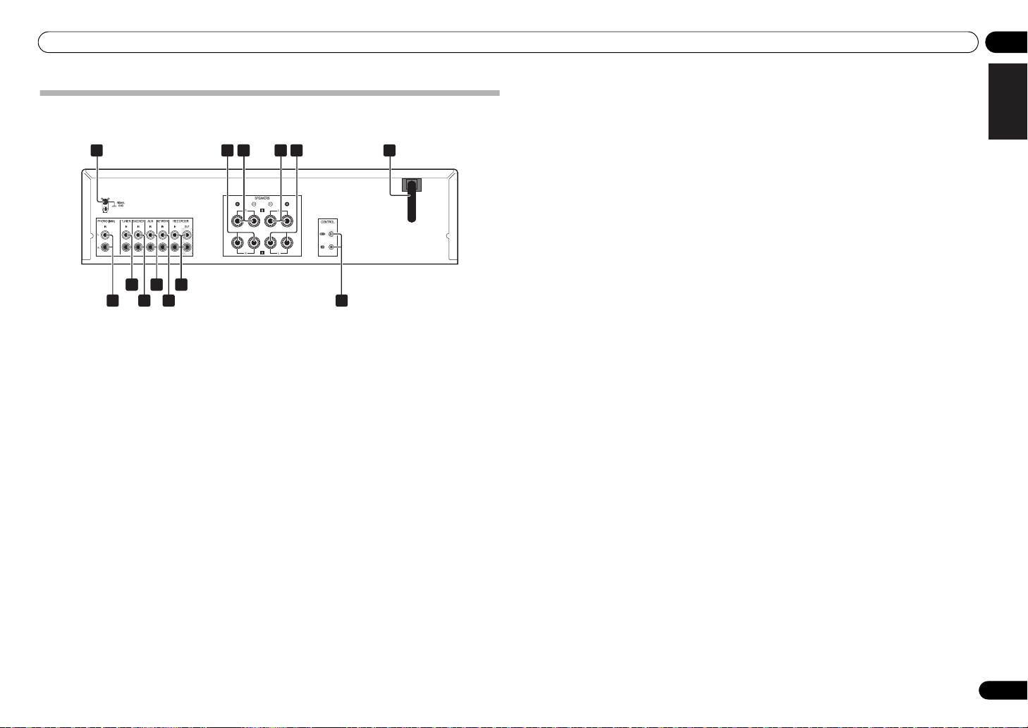
Rear panel
See pages 6 to 7 for details regarding connections.
1 6
28 2
10
2
12
7
9
11
1 GND (Turntable ground) terminal
This ground terminal is designed to help reduce noise
when a turntable is connected. It is not a safety ground.
2
SPEAKERS A
SPEAKERS B
3
SPEAKERS B
4
5
SPEAKERS A
6 Power cord
PHONO (MM) IN
7
8
TUNER IN
SACD/CD IN
9
terminals (Right channel)
terminals (Right channel)
terminals (Left channel)
terminals (Left channel)
terminals
terminals
terminals
2132 23 24 25
10
11
12
13
AUX IN
terminals
NETWORK IN
RECORDER IN/OUT
CONTROL IN/OUT
terminals
terminals
jack
English
DeutschFrançais
Italiano Español Русский
Nederlands
En
9
Page 10
03 Controls and displays
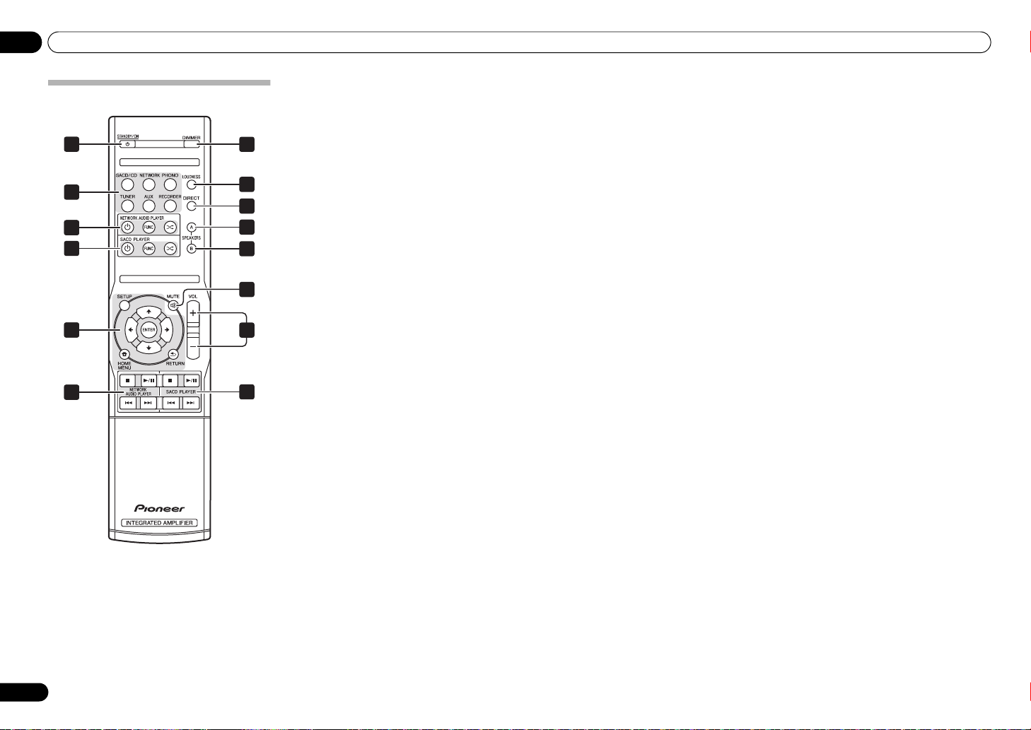
Remote control
1
2
33
4
33
33
5
6
7
8
9
10
11
4
1
STANDBY/ON
Switches the amplifier between standby and on.
2 Input selector buttons
Press to select an input source. These select the
component connected to the corresponding input on the
rear panel.
3 NETWORK AUDIO PLAYER control
buttons
Use to control Pioneer network audio player.
4 SACD PLAYER control buttons
Use to control Pioneer SACD player.
(Cannot be used to perform playback/pause on the
PD-D6/PD-D6MK2/PD-D9/PD-D9MK2 models.)
5
DIMMER
This button allows the illumination of the unit's front
panel indicators to be set in three levels (does not affect
the STANDBY indicator).
6
LOUDNESS
Use to set the loudness circuit ON/OFF (page 8).
7
DIRECT
Press to access Direct listening (page 8).
8
SPEAKERS A
Use this button to listen to the speaker system
connected to SPEAKERS A terminals.
9
SPEAKERS B
Use this button to listen to the speaker system
connected to SPEAKERS B terminals.
10
MUTE
Mutes/unmutes the sound.
11
VOLUME +/–
Use to set the listening volume.
button/indicator
button/indicator
10
En
Page 11

Operation 04
SACD/CD player
Network audio player
Turntable
Tuner
iPod dock, etc
CD recorder or
tape deck
Playback
Playback
Chapter 4:
Operation
Set the power to Standby
1 Press the remote control’s
button.
ON
STANDBY/
Playback
The next time you wish to turn on the power, press the
iPod
Music>
Extras>
Settings>
Shuffle Songs
Backlight
N-50
/I STANDBY/ON
STANDBY
PURE AUDIO Hi-Bit 32
iPod/USB
5V2.1A
NETWORK AUDIO PLAYER
FUNCTION
MENU
62
3566
remote control’s STANDBY/ON button.
• If the front panel’s STANDBY/ON button is
pressed, the power will be turned off. In this case, if
the power is off, pressing the remote control’s
STANDBY/ON button will not turn on the power. To
turn on the power again, press the front panel’s
STANDBY/ON button.
Note
• If the power cord is disconnected when the unit is
in the standby mode the unit will turn off, but when
the cord is then reconnected, the unit will not
automatically turn on. After reconnecting the
power cord, press the remote control’s
STANDBY/ON button to turn the power on.
English
DeutschFrançais
Italiano Español Русский
1 Turn on the power of the playback
component.
2 Turn power ON to the unit.
• If the unit is in the standby mode, press the remote
control’s STANDBY/ON button.
3 Select the source you want to playback.
Select the playback component.
• When using the front panel controls, rotate the
INPUT SELECTOR knob.
4 Start playback of the component you
selected in step 1.
5 Adjust playback volume with
control.
6 Adjust the tone to your preference using
BASS
the
LOUDNESS
If the DIRECT button has been set to ON, these controls
are disabled.
and
button.
TREBLE
controls, and
VOLUME
Nederlands
11
En
Page 12

04 Operation
SACD/CD player
Network audio player
Turntable
Tuner
iPod dock, etc
Audio recording component
(CD recorder, tape deck, etc.)
Playback
Recording
Making an audio recording
You can make an audio recording from any audio source connected to the amplifier.
N-50
NETWORK AUDIO PLAYER
FUNCTION
1 Select the source you want to record.
2 Start recording, then start playback of
the source component.
/I STANDBY/ON
STANDBY
PURE AUDIO Hi-Bit 32
iPod/USB
5V2.1A
To set for automatic standby status (Auto Power Down)
When this condition is set, if no input signal is detected for 30 minutes, the unit will automatically enter standby
status.
iPod
Music>
Extras>
Settings>
Shuffle Songs
Backlight
MENU
1 If the unit’s power is ON, hold the unit’s front-panel
button depressed simultaneously for three seconds.
When this condition is set to ON, the STANDBY/APD indicator on the unit’s front panel will light green. Press the
buttons again to disable the setting.
DIRECT
button and
LOUDNESS
• The factory default setting is OFF.
Note
1
Depending on the device connected, excessive noise produced by the device may be interpreted as an audio
signal, thus preventing the Automatic Power-Down function from operating.
Restoring all the settings to the factory default settings
1 When power is in standby mode, hold the front-panel’s DIRECT button and
SPEAKERS A button depressed simultaneously for five seconds.
2 Turn power ON to the unit.
12
En
Page 13

Additional information 05
Chapter 5:
Cleaning the unit
Additional information
Troubleshooting
Incorrect operations are often mistaken for trouble and malfunctions. If you think that there is something wrong with
this component, check the points below. Sometimes the trouble may lie in another component. Investigate the other
components and electrical appliances being used. If the trouble cannot be rectified even after exercising the checks
listed below, ask your nearest Pioneer authorized service center or your dealer to carry out repair work.
• If the unit does not operate normally due to external effects such as static electricity disconnect the power plug
from the outlet and insert again to return to normal operating conditions.
Problem Remedy
The power does not turn on. • Is the power plug disconnected from the power outlet? Connect the power plug
Power turns off. •Is the Auto Power Down function turned ON? If you do not want the power to turn off
During playback, sound stops, and
the
STANDBY/APD
red at about 1 second intervals.
During playback, sound stops, and
the
STANDBY/APD
red at about 2 second intervals.
When power is turned on, the
STANDBY/APD
irregular intervals.
No sound is output when a funct ion is
selected.
No sound from one speaker. •Are the connection cables or speaker cables disconnected on one side? Reconnect
Can’t operate the remote
control.
indicator flashes
indicator flashes
indicator flashes at
correctly to its outlet (page 7).
automatically, disable the Auto Power Down function (page 12).
•The unit’s internal temperature has risen and the safety circuit has operated.
- Turn power OFF, and allow the unit to cool before turning the power ON again.
- Install the unit in a location with better ventilation.
- Confirm that the unit is installed correctly; if the unit is turned on again without
being allowed to cool, the same symptoms may appear (page 5).
•Are you using speakers with impedance values not supported by this unit? Confirm
the speaker’s nominal impedance value (page 7).
•Are any speaker cables loose from the
wires or the surface of the rear panel? Disconnect the power cord and reconnect the
speaker cables correctly (page 7).
•The unit’s circuitr y is damaged. Disconnect the power cord and consult your dealer
or nearest
Pioneer authorized service center
•A connection cable is disconnected or connected improperly. Check your
connections (page 6).
•Connectors or pin plugs on a cable are dirty. Wipe off any dirt from connectors and
pin plugs.
•Confirm that the unit’s input selector is set to the desired playback component. Set
selector correctly (page 11).
•Press
MUTE
on the remote control to turn muting off (page 10).
securely (page 6).
•Replace the battery (page 5).
•Operate within 7 m, 30 ºof the remote sensor on the front panel (page 5).
•Remove the obstacle or operate from another position.
•Avoid exposing the remote sensor on the front panel to direct light.
•Is the control cord for one component connected improperly? Confirm correct
connections (page 7).
SPEAKERS
terminals and touching other
.
• Use a polishing cloth or dry cloth to wipe off dust
and dirt.
• When the surface is dirty, wipe with a soft cloth
dipped in some neutral cleanser diluted five or six
times with water, and wrung out well, and then
wipe again with a dry cloth. Do not use furniture
wax or cleansers.
• Never use thinners, benzine, insecticide sprays or
other chemicals on or near this unit, since these
will corrode the surface.
English
DeutschFrançais
Italiano Español Русский
Nederlands
13
En
Page 14

05 Additional information
Specifications
Amplifier section
Power output specification is for when power supply is 120 V.
• Continuous power output (both
channels driven at 20 Hz to 20 kHz)
THD 0.1 %, 4 Ω . . . . . . . . . . . . . . . . . . . . . . .50 W + 50 W
THD 0.05 %, 8 Ω . . . . . . . . . . . . . . . . . . . . . . .30 W+30 W
Audio section
• Input (Sensitivity/Impedance)
SACD/CD, NETWORK, TUNER, AUX, RECORDER
. . . . . . . . . . . . . . . . . . . . . . . . . . . . . . . . . . . 200 mV/50 kΩ
PHONO (MM) . . . . . . . . . . . . . . . . . . . . . . . 2.8 mV/50 kΩ
• Output (Level/Impedance)
RECORDER OUT. . . . . . . . . . . . . . . . . . . . 200 mV/2.2 kΩ
PHONES . . . . . . . . . . . . . . . . . . . . . . . . . . . . 250 mV/32 Ω
• Frequency response
SACD/CD, NETWORK, TUNER, AUX, RECORDER
. . . . . . . . . . . . . . . . . . . . . . . . . . . 5 Hz to 100 kHz dB*
PHONO (MM) . . . . . . . . . . . . . 20 Hz to 20 kHz ±0.5 dB*
* Measured with DIRECT button switched on.
• Tone control
(When VOLUME is set to
Bass . . . . . . . . . . . . . . . . . . . . . . . . . . . . ± 10 dB (100 Hz)
Treble . . . . . . . . . . . . . . . . . . . . . . . . . . . ± 10 dB (10 kHz)
• Signal-to-Noise Ratio (IHF SHORTED,
A-NETWORK)
SACD/CD, NETWORK, TUNER, AUX, RECORDER
. . . . . . . . . . . . . . . . . . . . . . . . . . . . . . . . . . . . . . . .105 dB*
PHONO (MM, 2.8 mV input) . . . . . . . . . . . . . . . . . 77 dB*
* Measured with DIRECT button switched on.
• Speaker load impedance
A, B. . . . . . . . . . . . . . . . . . . . . . . . . . . . . . . . . . 4 Ω to 16 Ω
A+B . . . . . . . . . . . . . . . . . . . . . . . . . . . . . . . . . 8 Ω to 32 Ω
Bi-wiring. . . . . . . . . . . . . . . . . . . . . . . . . . . . . . 4 Ω to 16 Ω
-
30 dB)
Miscellaneous
Power requirements
. . . . . . . . . . . . . . . . . . . . . . . . . . . . . . . . . AC 120 V, 60 Hz
Power consumption . . . . . . . . . . . . . . . . . . . . . . . . 135 W
In standby . . . . . . . . . . . . . . . . . . . . . . . . . . . . . . . . .0.3 W
Dimensions
. . . . . . . . . . . . .435 mm (W) x 128 mm (H) x 360 mm (D)
Weight (without package) . . . . . . . . . . . . . . . . . . . . 7.2 kg
Accessories
Remote control . . . . . . . . . . . . . . . . . . . . . . . . . . . . . . . . . 1
AAA/IEC R03 dry cell batteries . . . . . . . . . . . . . . . . . . . .2
Operating instructions (This document)
Note
• Specifications and the design are subject to
possible modifications without notice, due to
improvements.
• Corporation and product names mentioned herein
are trademarks or registered trademarks of the
respective corporations.
14
En
© 2012 PIONEER CORPORATION.
All rights reserved.
Page 15

Additional information 05
English
DeutschFrançais
Italiano Español Русский
Nederlands
15
En
Page 16

IMPORTANT
ATTENTION
DANGER D´ELECTROCUTION
NE PAS OUVRIR
Ce symbole de l’éclair, placé dans un
triangle équilatéral, a pour but d’attirer
l’attention de l’utilisateur sur la présence, à
l’intérieur du coffret de l’appareil, de
“tensions dangereuses” non isolées d’une
grandeur suffisante pour représenter un
risque d’électrocution pour les êtres
humains.
AVERTISSEMENT
Cet appareil n’est pas étanche. Pour éviter les risques
d’incendie et de décharge électrique, ne placez près de
lui un récipient rempli d’eau, tel qu’un vase ou un pot
de fleurs, et ne l’exposez pas à des gouttes d’eau, des
éclaboussures, de la pluie ou de l’humidité.
AVERTISSEMENT
Avant de brancher l’appareil pour la première, lisez
attentivement la section suivante.
La tension de l’alimentation électrique disponible
varie selon le pays ou la région. Assurez-vous que
la tension du secteur de la région où l’appareil sera
utilisé correspond à la tension requise (par ex. 230
V ou 120 V), indiquée sur le panneau arrière.
ATTENTION :
POUR ÉVITER TOUT RISQUE
D’ÉLECTROCUTION, NE PAS ENLEVER LE
COUVERCLE (NI LE PANNEAU ARRIÈRE).
AUCUNE PIÈCE RÉPARABLE PAR
L’UTILISATEUR NE SE TROUVE À
L’INTÉRIEUR. CONFIER TOUT ENTRETIEN À
UN PERSONNEL QUALIFIÉ UNIQUEMENT.
D3-4-2-1-3_A1_Fr
D3-4-2-1-4*_A1_Fr
Ce point d’exclamation, placé dans un
triangle équilatéral, a pour but d’attirer
l’attention de l’utilisateur sur la présence,
dans les documents qui accompagnent
l’appareil, d’explications importantes du
point de vue de l’exploitation ou de
l’entretien.
D3-4-2-1-1_A1_Fr
AVERTISSEMENT
Pour éviter les risques d’incendie, ne placez aucune
flamme nue (telle qu’une bougie allumée) sur
l’appareil.
D3-4-2-1-7a_A1_Fr
PRÉCAUTION DE VENTILATION
Lors de l’installation de l’appareil, veillez à laisser un
espace suffisant autour de ses parois de manière à
améliorer la dissipation de chaleur (au moins 30 cm sur
le dessus, 10 cm à l’arrière et 10 cm de chaque côté).
AVERTISSEMENT
Les fentes et ouvertures du coffret sont prévues pour la
ventilation, pour assurer un fonctionnement stable de
l’appareil et pour éviter sa surchauffe. Pour éviter les
risques d’incendie, ne bouchez jamais les ouvertures et
ne les recouvrez pas d’objets, tels que journaux, nappes
ou rideaux, et n’utilisez pas l’appareil posé sur un tapis
épais ou un lit.
D3-4-2-1-7b*_A1_Fr
Milieu de fonctionnement
Température et humidité du milieu de fonctionnement :
De +5 °C à +35 °C (de +41 °F à +95 °F) ; Humidité
relative inférieure à 85 % (orifices de ventilation non
obstrués)
N’installez pas l’appareil dans un endroit mal ventilé ou
un lieu soumis à une forte humidité ou en plein soleil
(ou à une forte lumière artificielle).
D3-4-2-1-7c*_A1_Fr
Si la fiche d’alimentation secteur de cet appareil ne
convient pas à la prise secteur à utiliser, la fiche doit
être remplacée par une appropriée. Ce
remplacement et la fixation d’une fiche secteur sur le
cordon d’alimentation de cet appareil doivent être
effectués par un personnel de service qualifié. En cas
de branchement sur une prise secteur, la fiche de
coupure peut provoquer une sérieuse décharge
électrique. Assurez-vous qu’elle est éliminée
correctement après sa dépose.
L’appareil doit être déconnecté en débranchant sa
fiche secteur au niveau de la prise murale si vous
prévoyez une période prolongée de non utilisation
(par exemple avant un départ en vacances).
D3-4-2-2-1a_A1_Fr
ATTENTION
L’interrupteur /I STANDBY/ON de cet appareil ne
coupe pas complètement celui-ci de sa prise secteur.
Comme le cordon d’alimentation fait office de
dispositif de déconnexion du secteur, il devra être
débranché au niveau de la prise secteur pour que
l’appareil soit complètement hors tension. Par
conséquent, veillez à installer l’appareil de telle
manière que son cordon d’alimentation puisse être
facilement débranché de la prise secteur en cas
d’accident. Pour éviter tout risque d’incendie, le
cordon d’alimentation sera débranché au niveau de
la prise secteur si vous prévoyez une période
prolongée de non utilisation (par exemple avant un
départ en vacances).
D3-4-2-2-2a*_A1_Fr
Page 17

Ce produit est destiné à une utilisation domestique
générale. Toute panne due à une utilisation autre qu'à
des fins privées (comme une utilisation à des fins
commerciales dans un restaurant, dans un autocar
ou sur un bateau) et qui nécessite une réparation
sera aux frais du client, même pendant la période de
garantie.
K041_A1_Fr
La protection de votre ouïe est entre vos
mains
Pour assurer le rendement optimal de votre matériel
et – plus important encore – la protection de votre ouïe,
réglez le volume à un niveau raisonnable. Pour ne pas
altérer votre sens de la perception, le son doit être clair
mais ne produire aucun vacarme et être exempt de
toute distorsion. Votre ouïe peut vous jouer des tours.
Avec le temps, votre système auditif peut en effet
s’adapter à des volumes supérieurs, et ce qui vous
semble un « niveau de confort normal » pourrait au
contraire être excessif et contribuer à endommager
votre ouïe de façon permanente. Le réglage de votre
matériel à un volume sécuritaire AVANT que votre ouïe
s’adapte vous permettra de mieux vous protéger.
CHOISISSEZ UN VOLUME SÉCURITAIRE:
• Réglez d’abord le volume à un niveau inférieur.
• Montez progressivement le volume jusqu’à un niveau
d’écoute confortable ; le son doit être clair et exempt
de distorsions.
• Une fois que le son est à un niveau confortable, ne
touchez plus au bouton du volume.
N’OUBLIEZ PAS DE RESPECTER LES
DIRECTIVES SUIVANTES:
• Lorsque vous montez le volume, assurez-vous de
pouvoir quand même entendre ce qui se passe
autour de vous.
• Faites très attention ou cessez temporairement
l’utilisation dans les situations pouvant s’avérer
dangereuses.
• N’utilisez pas des écouteurs ou un casque d’écoute
lorsque vous opérez un véhicule motorisé ; une telle
utilisation peut créer des dangers sur la route et est
illégale à de nombreux endroits.
S001a_A1_Fr
NOTE IMPORTANTE SUR LE CABLE
D’ALIMENTATION
Tenir le câble d’alimentation par la fiche. Ne pas
débrancher la prise en tirant sur le câble et ne pas
toucher le câble avec les mains mouillées. Cela risque
de provoquer un court-circuit ou un choc électrique. Ne
pas poser l’appareil ou un meuble sur le câble. Ne pas
pincer le câble. Ne pas faire de noeud avec le câble ou
l’attacher à d’autres câbles. Les câbles d’alimentation
doivent être posés de façon à ne pas être écrasés. Un
câble abîmé peut provoquer un risque d’incendie ou un
choc électrique. Vérifier le câble d’alimentation de
temps en temps. Contacter le service après-vente
PIONEER le plus proche ou le revendeur pour un
remplacement.
S002*_A1_Fr
Merci d’avoir acheté ce produit
Pioneer.
Veuillez lire entièrement ce mode d’emploi afin de
pouvoir faire fonctionner correctement le modèle que
vous avez choisi. Après avoir fini la lecture du mode
d’emploi, placez-le dans un endroit sûr afin de pouvoir
vous y référer plus tard
.
Table des
matières
01 Préparatifs
Contenu de la boîte . . . . . . . . . . . . . . . . . . . . . . . .4
Chargement des piles de la télécommande . . . . . .4
Utilisation de la télécommande . . . . . . . . . . . . . . . .4
Installation de l’amplificateur . . . . . . . . . . . . . . . .4
02 Raccordement
Raccordements des câbles . . . . . . . . . . . . . . . . . . 5
A propos de “bi-câblage (bi-wiring)”. . . . . . . . . . . . 5
Connexion des câbles d’enceinte. . . . . . . . . . . . . . 6
Raccordement des câbles audio . . . . . . . . . . . . . . 6
Commande centralisée avec d’autres
composants Pionner . . . . . . . . . . . . . . . . . . . . . . . 6
Branchement. . . . . . . . . . . . . . . . . . . . . . . . . . . . .6
03 Commandes et afficheur
Panneau avant. . . . . . . . . . . . . . . . . . . . . . . . . . . . 7
Panneau arrière. . . . . . . . . . . . . . . . . . . . . . . . . . .8
Télécommande . . . . . . . . . . . . . . . . . . . . . . . . . . . 9
04 Fonctionnement
Lecture . . . . . . . . . . . . . . . . . . . . . . . . . . . . . . . . 10
Réglage de la puissance sur la mise en veille . . . .10
Réalisation d’un enregistrement audio . . . . . . . . 11
Pour régler un statut de veille automatique
(fonction de mise hors tension automatique). . . .11
Pour restaurer tous les réglages sur les
valeurs par défaut . . . . . . . . . . . . . . . . . . . . . . . .11
05 Informations supplémentaires
Guide de dépannage . . . . . . . . . . . . . . . . . . . . . . 12
Nettoyage de l’unité. . . . . . . . . . . . . . . . . . . . . . . 12
Spécifications . . . . . . . . . . . . . . . . . . . . . . . . . . . 13
3
Page 18

01 Préparatifs
Chapitre 1 :
Préparatifs
Contenu de la boîte
Veuillez confirmer que les accessoires suivants sont
présents dans la boîte quand vous l’ouvrez.
•Télécommande
• Piles sèches AAA/IEC R03 x2
• Mode d’emploi (ce document)
Remarque
• Les illustrations des instructions opérationnelles
peuvent avoir été modifiées ou simplifiées dans le
but de clarification et en conséquence peuvent
différer de l’apparence actuelle du produit.
Chargement des piles de la
télécommande
1 Ouvrez le couvercle arrière.
2 Placez les piles neuves, en faisant
correspondre la polarité à celle du boîtier.
3 Fermez le couvercle arrière.
Les piles incluses avec l’unité ont été fournies pour
permettre de contrôler le fonctionnement du produit et
ne dureront pas longtemps. Nous recommandons
d’utiliser des piles alcalines qui ont une durée de vie
utile plus longue.
AVERTISSEMENT
• N’utilisez ni ne conservez les piles sous la lumière
directe du soleil ou dans un endroit excessivement
chaud, comme une voiture ou à proximité d’un
appareil de chauffage. Les piles risqueraient de
fuir, de surchauffer, d’exploser ou de s’enflammer.
Leur durée de vie ou leur performance pourrait
également être réduite.
Attention
Toute utilisation incorrecte des piles peut entraîner des
accidents, par exemple une fuite ou une explosion.
Respectez les précautions suivantes :
• Lorsque vous placez les piles, prenez soin de ne pas
endommager les ressorts des bornes des piles .
• Ne pas utiliser de piles autres que celles qui sont
indiquées. Ne pas utiliser non plus une pile neuve
avec une pile usée.
• Lorsque vous installez les piles dans la
télécommande, orientez-les batteries dans la
bonne direction en respectant la polarité ( et ).
• Ne pas chauffer, ni démonter, ni ne jeter les piles
dans le feu ou l’eau.
• La tension des piles peut différer l’une de l’autre et
cela même si leur type et forme sont identiques.
Utiliser ensemble uniquement des piles du même
type.
• Pour éviter que les piles ne fuient, enlever les piles
lorsque le produit n’est pas censé être utilisé
pendant une période prolongée (à savoir 1 mois ou
plus). Si les piles ont fuit, nettoyer soigneusement
l’intérieur du compartiment et placer ensuite les
piles. Si une pile fuit et que du liquide entre en
contact avec votre peau, nettoyer à grande quantité
d’eau.
• Lorsque vous jetez des piles usées, veuillez vous
conformer aux normes gouvernementales ou à la
réglementation des institutions publiques
environnementales en vigueur dans votre pays ou
région.
Utilisation de la télécommande
La télécommande a une portée d’environ 7 m avec un
angle de 30° par rapport au capteur de télécommande.
30 °
30 °
7 m
Gardez à l’esprit ce qui suit lorsque vous utilisez la
télécommande :
• Assurez-vous de l’absence d’obstacles entre la
télécommande et le capteur de l’appareil.
• La télécommande risque de ne pas fonctionner
correctement si la lumière du soleil ou une lampe
fluorescente puissante éclaire le capteur de
l’appareil.
• Les télécommandes de différents appareils
peuvent interférer entre elles. Evitez d’utiliser des
télécommandes commandant d’autres
équipements situés à proximité de cet appareil.
• Remplacez les piles lorsque vous constatez une
diminution de la portée de fonctionnement de la
télécommande.
Installation de l’amplificateur
Lors de l’installation de l’appareil, assurez-vous que ce
dernier est posé sur une surface plane et stable.
•
N’installez pas l’appareil dans les endroits suivants :
– sur un téléviseur couleur (les images à l’écran
pourraient être déformées)
– à proximité d’une platine à cassettes (ou d’un
appareil qui produit un champ magnétique). Le son
pourrait s’en trouver affecté.
– à la lumière directe du soleil
– à l’humidité
– à des températures extrêmes
– en présence de vibrations ou autres mouvements
– à la poussière
– à la fumée ou aux émanations graisseuses
(cuisine par ex.)
• Ne pas installer l’unité sur un divan ou tout autre
objet/matériau ayant des caractéristiques
absorbantes sous risque d’affecter la qualité du
son.
4
Frca
Page 19

Raccordement 02
Chapitre 2 :
Raccordement
Raccordements des câbles
Attention
• Avant d’effectuer ou de modifier les raccordements, mettez l’appareil hors tension et débranchez le cordon
d’alimentation de la prise secteur.
• Connectez le cordon d’alimentation après avoir effectué toutes les connexions entre les appareils.
Système d’enceinte B
Gauch
Lecteur SACD/CD
R
L
Lecteur audio réseau
R
L
Droite
Panneau arrière
Attention
•La borne SIGNAL GND est fournie pour réduire le
bruit lors de la connexion de l’unité aux
composants, tels que la platine.
• Ne pas connecter les bornes PHONO (MM) à un
autre composant qu’une platine; ne pas connecter
non plus une platine dotée d’un égalisateur intégré.
Un son émis trop fort peut se produire, ce qui
endommagerait les enceintes ou les autres
appareils.
• Les bornes de l’unité
pour être utilisées avec des des
cartouches de type MM (à aimant mobile). Ne pas
utiliser les les
bobine mobile).
• Assurez-vous de ne pas plier les câbles par dessus
cette unité (comme indiqué dans l’illustration). Si
cela se produit, le champ magnétique produit par
les transformateurs dans cette unité peut
provoquer un ronflement des enceintes.
PHONO (MM)
platines dotée
ont été conçues
platines dotée
s de
s de cartouches MC (à
• Au cours de la lecture, assurez-vous que les
boutons SPEAKERS A et SPEAKERS B sont sur
Marche (ON) (page 7).
Système des
Droite
HIGH
LOW
Panneau
arrière
Enlevez la tige de
court-circuit entre
les bornes + et –.
Système des
Gauch
HIGH
LOW
English
DeutschFrançais
Italiano Español Русский
Nederlands
LRL
• Si votre platine dispose d’un fil de mise à la terre,
R
fixez-le à la borne de terre de cet amplificateur.
Remarque
• Lors de la connexion d’un enregistreur à bande, le
bruit de fond peut être perçu, selon l’emplacement
de l’installation. Ce bruit provient d’une fuite du
transformateur de l’amplificateur. Dans ce cas,
R
Platine
R
OUTPUT
L
R
Syntoniseur
L
R
L
R
Station d’accueil
iPod, etc.
AUDIO
RL
OUTPUT
iPod
Music>
Extras>
Settings>
Shuffle Songs
Backlight
MENU
d’alimentation
REC
PLAY
L
R
Enregistreur CD
ou à bande
L
L
R
R
Cordon
Droite
Système d’enceinte A
Gauch
LRLRL
LRL
changez l’emplacement de l’installation ou
distancez davantage la platine de l’amplificateur.
• iPod est une marque commerciale d’Apple Inc.,
enregistrées aux États-Unis et dans d’autres pays.
A propos de “bi-câblage (bi-wiring)”
Cette unité peut être utilisée avec des enceintes
prenant en charge le bi-câblage. Toujours raccorder
correctement la haute fréquence et la basse
fréquence.
Attention
• Lorsque vous utilisez un bi-câblage pour connecter
les enceintes, assurez-vous d’enlever les tiges de
court-circuit HIGH et LOW fournies avec les
haut-parleurs pour ne pas créer d’effets adverses
sur l’amplificateur. Pour de plus amples
informations, consultez les instructions fournies
avec les enceintes.
• Lorsque vous utilisez des enceintes avec des
circuits de réseau amovibles, si le réseau est
enlevé, aucun effet ne se produira et les enceintes
peuvent subir des dommages.
• Vous pouvez alternativement connecter les bornes
SPEAKERS A sur HIGH et celles sur LOW
SPEAKERS B (à l’inverse de ce qui est illustré).
5
Frca
Page 20

02 Raccordement
Connexion des câbles d’enceinte
1 Entortillez l’âme des câbles.
2 Desserrez l’écrou sur la borne
et introduisez le câble de l’enceinte dans le
trou exposé dans la borne.
3 Resserrez l’écrou de la borne.
123
10 mm
• Pour utiliser des câbles de haut-parleur dotés de
fiches bananes, vissez la borne du haut-parleur
complètement fer mée puis branchez la fiche
banane dans l’extrémité de la borne du
haut-parleur.
SPEAKERS
• Assurez-vous que tous les fils dénudés d’enceinte
sont entortillés ensemble et totalement introduits
dans la borne de l’enceinte. Si l’un des fils dénudés
entre en contact avec le panneau arrière,
l’alimentation sera automatiquement coupée par
mesure de sécurité.
Raccordement des câbles audio
Connectez la fiche blanche à la prise gauche (L) et la
fiche rouge à la prise droite (R). Assurez-vous de bien
brancher les fiches dans les prises.
Gauche
(blanche)
Droite (rouge)
Commande centralisée avec d’autres
composants Pionner
De nombreux composants Pionneer dotés de prises
CONTROL IN/OUT peuvent être connectés aux unités
A-20 centralisant la commande des composants via le
télécapteur sur l’A-20. Cette centralisation permet
d’utiliser une télécommande dont les composants ne
sont pas munis d’un télécapteur ou sont installés à des
emplacements inaccessibles par le télécapteur.
IN
OUT
CONTROL
Vers d’autres
composants Pioneer
munis de prises
CONTROL IN/OUT
Vers d’autres
composants
Pioneer munis
d’une prise
CONTROL IN
Branchement
Important
• Lorsque vous devez vous absenter ou quelle que
soit la situation où l’unité ne sera pas utilisée
pendant une longue durée, toujours déconnecter le
cordon d’alimentation de ses prises. Les réglages
in tern es s ont tou jou rs c onse rvé s et cel a mê me s i le
cordon d’alimentation est déconnecté de sa prise
pendant une longue période.
• Si le cordon d’alimentation doit être déconnecté,
assurez-vous d’appuyer sur le bouton
/I
STANDBY/ON sur le panneau avant de l’unité
de manière à ce que l’A-20 soit sur Arrêt (OFF) .
Après avoir effectué toutes les connexions, branchez
l’unité dans une prise CA.
Panneau arrière
Attention
• Lorsque vous utilisez uniquement un jeu de
bornes de l’enceinte (SPEAKERS A ou SPEAKERS
B), ou lorsque vous utilisez des connexions
bi-câblage, l’enceinte utilisée doit disposer
d’une impédance nominale entre 4 Ω et 16 Ω.
Lorsque vous utilisez des jeux de bornes, les
enceintes connectées doivent disposer d’une
impédance nominale entre 8 Ω et 32 Ω. Pour de
plus amples informations sur la valeur de
l’impédance, consultez les instructions jointes
aux enceintes.
• Vérifiez que les bornes positive et négative (+/–) sur
l’amplificateur correspondent à celles des
enceintes.
• Les bornes des haut-parleurs sont sous une
tension ACTIVE DANGEREUSE. Pour éviter tout
risque de décharge électrique lors du branchement
et du débranchement des câbles d’enceinte,
débranchez le cordon d’alimentation avant de
toucher des parties non isolées.
6
Frca
A-20
Visez la télécommande
Télécommande
A-20
Remarque
• Pour établir la connexion, utilisez un cordon minifiche mono en vente dans le commerce (sans
résistance).
•
Lors de la connexion des prises
des cordons audio en vente dans le commerce
doivent être utilisés pour établir les connexions
analogiques. La connexion des prises CONTROL
IN/OUT ne suffit pas à à assurer un contrôle
adéquat du système.
• Lorsqu’un cordon de commande est connecté à la
prise de l’A-20 CONTROL IN, il est impossible de
contrôler l’unité en pointant la télécommande à
l’A-20 (le télécapteur est automatiquement
désactivé).
en direction du capteur
sur l’A-20.
CONTROL IN/OUT
Vers la prise CA
Cordon d’alimentation
1 Branchez le cordon d’alimentation dans
une prise CA.
,
Page 21

Commandes et afficheur 03
Chapitre 3 :
Commandes et afficheur
Panneau avant
1
2 54
3
6
1/I
STANDBY/ON
Ce bouton permet de mettre l’amplificateur sous/hors
tension.
Lors de la mise sous tension, l’indicateur au centre du
bouton s’allume.
2 Indicateur
Lorsque l’alimentation est en mode veille, l’indicateur
s’allume en rouge. Lorsque la fonction de mise hors
tension automatique (APD) est activée, l’indicateur
s’allume en vert (page 11).
3 Bouton/indicateur
Ce bouton permet d’écouter le système d’enceinte
connecté aux bornes SPEAKERS A.
On : L’indicateur s’allume. Le son est entendu du
système d’enceinte. (Le son sera également émis de la
prise PHONES).
Off : L’indicateur s’éteint. Aucun son n’est entendu du
système d’enceinte. Réglez à cette position lorsque vous
utilisez des écouteurs.
7
8
STANDBY/APD
SPEAKERS A
9
10 11 12
13
4 Bouton/indicateur
Ce bouton permet d’écouter le système d’enceinte
connecté aux bornes SPEAKERS B.
On : L’indicateur s’allume. Le son est entendu du
système d’enceinte. (Le son sera également émis de la
prise PHONES).
Off : L’indicateur s’éteint. Aucun son n’est entendu du
système d’enceinte. Réglez à cette position lorsque vous
utilisez des écouteurs.
5 Bouton/indicateur
Utilisez lorsque vous utilisez à des niveaux faibles.
On : L’indicateur s’allume : Augmente les fréquences
hautes et basses pour donner du punch aux lectures
même à niveau sonore faible.
Off : L’indicateur s’éteint: Doit en principe rester dans
cette position.
• Ce bouton ne fonctionne pas lorsque le bouton
DIRECT est en position de marche.
• Lorsque vous augmentez le son, la quantité de
changement produit par le circuit LOUDNESS est
réduite.
SPEAKERS B
LOUDNESS
6 Capteur de télécommande
Reçoit les signaux émis par la télécommande (page 4).
7Prise
Utilisez pour connecter des écouteurs. Pas de son
produit lorsque le bouton POWER AMP DIRECT est sur
ON.
8 Bouton/indicateur DIRECT
On : L’indicateur s’allume : Lorsque ce bouton est sur
ON, les signaux sonores sont émis directement sans
passer par les divers circuits de réglage (BASS, TREBLE,
BALANCE, LOUDNESS). Les signaux sont ainsi
reproduits très fidèlement mais les réglages effectués
avec les commandes BASS, TREBLE, BALANCE ou
LOUDNESS sont ignorés.
Off : L’indicateur s’éteint: Le signal passe par divers
circuits d’ajustement de fréquence. Lorsque l’indicateur
est sur OFF, les réglages peuvent être effectués avec les
commandes BASS, TREBLE, BALANCE et LOUDNESS.
9 Commande de la tonalité
Utilisez pour régler la tonalité basse fréquence. La
position centrale correspond à une position plate
(normale). Lorsque vous tournez sur la droite, les
tonalités basse fréquence sont accentuées; lorsque
vous tournez sur la gauche, les tonalités basse
fréquence sont atténuées.
10 Commande de la tonalité
Utilisez pour régler la tonalité haute fréquence. La
position centrale correspond à une position plate
(normale). Lorsque vous tournez sur la droite, les
tonalités haute fréquence sont accentuées; lorsque vous
tournez sur la gauche, les tonalités haute fréquence sont
atténuées.
11
Doit en principe rester au centre. Réglez l’équilibre si le
son est plus fort d’une enceinte que de l’autre. Si le côté
droit est plus fort, tournez vers la gauche (L) et si le côté
gauche est plus fort, tournez vers la droite (R).
PHONES
BASS
• Ce bouton ne fonctionne pas lorsque le bouton
DIRECT est en position de marche.
TREBLE
• Ce bouton ne fonctionne pas lorsque le bouton
DIRECT est en position de marche.
Commande BALANCE
• Ce bouton ne fonctionne pas lorsque le bouton
DIRECT est en position de marche.
12 Commandes du VOLUME
Utilisez pour régler le niveau du volume. (Permet
également d’effectuer des réglages du volume sonore
des écouteurs.)
13 Touche/indicateur
Tournez le bouton dans le sens horaire ou anti-horaire
de manière à ce que l’indicateur s’allume pour la source
d’entrée souhaitée. Tournez le bouton dans le sens
horaire pour que l’indicateur s’allume sur la droite.
Tournez dans le sens anti-horaire pour que l’indicateur
s’allume sur la gauche. Lorsque vous appuyez sur le
bouton de la télécommande MUTE pour mettre le son
en sourdine, l’indicateur de la source d’entrée
sélectionné avec le bouton INPUT SELECTOR se met à
clignoter.
INPUT SELECTOR
English
DeutschFrançais
Italiano Español Русский
Nederlands
Frca
7
Page 22

03 Commandes et afficheur
Panneau arrière
Pour de plus amples informations sur les connexions, voir les pages 5-6.
1 6
28 2
10
2
12
7
9
11
1 Borne GND (mise à la terre de la platine)
Cette borne de terre a été conçue pour réduire le bruit
lorsqu’une platine est branchée. Il ne s’agit pas d’une
mise à la terre de sécurité.
2
SPEAKERS A
3
SPEAKERS B
SPEAKERS B
4
SPEAKERS A
5
bornes (canal droit)
bornes (canal droit)
bornes (canal gauche)
bornes (canal gauche)
6 Cordon d’alimentation
7
PHONO (MM)
TUNER
8
9
SACD/CD
IN bornes
IN bornes
IN bornes
2132 23 24 25
10
AUX
IN bornes
11
NETWORK
RECORDER IN/OUT
12
13
CONTROL IN/OUT
IN bornes
bornes
prise
8
Frca
Page 23

Commandes et afficheur 03
1
STANDBY/ON
Télécommande
1
2
33
4
33
33
5
6
7
8
9
10
11
4
Cette touche permet d’allumer l’amplificateur et de le
mettre en veille.
2 Boutons de sélection des entrées
Appuyez sur l’une de ces boutons pour sélectionner une
source d’entrée. Elles sélectionnent le composant
raccordé à l’entrée correspondante sur le panneau
arrière.
3 Boutons de commande du NETWORK
AUDIO PLAYER
Permet de contrôler le lecteur Pioneer audio en réseau.
4 Boutons de commande du SACD PLAYER
Permet de contrôler le lecteur SACD Pioneer.
(Ne pas utiliser pour effectuer une lecture/pause sur les
modèles PD-D6/PD-D6MK2/PD-D9/PD-D9MK2.)
5
DIMMER
Ce bouton permet d’allumer les indicateurs du panneau
avant de l’unité pour régler les trois niveaux (aucune
incidence sur l’indicateur STANDBY).
6
LOUDNESS
Utilisez pour activer/désactiver (ON/OFF) (page 7) le
circuit de la puissance sonore.
7
DIRECT
Permet d’accéder à la fonction d’écoute en mode direct
(page 7).
8
SPEAKERS A
Ce bouton permet d’écouter le système d’enceinte
connecté aux bornes SPEAKERS A.
9
SPEAKERS B
Ce bouton permet d’écouter le système d’enceinte
connecté aux bornes SPEAKERS B.
10
MUTE
Permet de couper/restaurer le son.
11
VOLUME +/–
Permet de régler le volume d’écoute.
bouton/indicateur
bouton/indicateur
English
DeutschFrançais
Italiano Español Русский
Nederlands
Frca
9
Page 24

04 Fonctionnement
Chapitre 4 :
Fonctionnement
Lecture
Platine
Lecteur SACD/CD
Lecture
1 Mettez sous tension le composant de
lecture.
2 Mettez l’unité sous tension.
• Si l’unité est en mode de veille, appuyez sur le
bouton de la télécommande STANDBY/ON.
Lecteur audio réseau
/I STANDBY/ON
STANDBY
PURE AUDIO Hi-Bit 32
iPod/USB
5V2.1A
NETWORK AUDIO PLAYER
FUNCTION
N-50
62
Station d’accueil iPod, etc.
Syntoniseur
iPod
Music>
Extras>
Settings>
Shuffle Songs
Backlight
MENU
Enregistreur CD
ou à bande
Lecture
3566
4 Débutez la lecture du composant que
vous avez sélectionné dans l’étape 1.
5 Réglez le volume de la lecture avec la
commande
VOLUME
.
Réglage de la puissance sur la mise en
veille
1 Appuyez sur le bouton de la
télécommande
La prochaine fois que vous remettrez sous tension,
appuyez sur le bouton STANDBY/ON de la
télécommande.
• Si le bouton STANDBY/ON est appuyé, l’unité
s’éteint. Dans ce cas, si l’alimentation est coupée,
vous ne pourrez pas remettre sous tension en
appuyant sur le bouton de la télécommande
STANDBY/ON. Pour remettre sous tension,
appuyez sur le bouton du panneau avant
STANDBY/ON.
Remarque
• Si le cordon de l’alimentation n’est pas branché
lorsque l’unité est en mode de veille, l’unité
s’éteindra. Toutefois lorsque le cordon est
rebranché, l’unité ne se remettra pas
automatiquement en marche. Après la
rebranchement du cordon d’alimentation, appuyez
sur le bouton de la télécommande
STANDBY/ON pour remettre sous tension.
STANDBY/ON
.
3 Sélectionnez la source que vous
souhaitez lire.
Sélectionnez le composant de lecture.
• Lorsque vous utilisez les commandes du panneau
avant, tournez le bouton INPUT SELECTOR.
10
Frca
6 Ajustez la tonalité à votre choix à l’aide
BASS
et
TREBLE
des commandes
LOUDNESS
bouton
Si le bouton DIRECT a été réglé sur ON, ces commandes
sont désactivées.
.
et du
Page 25

Fonctionnement 04
English
Réalisation d’un enregistrement audio
Vous pouvez faire un enregistrement audio à partir de n’importe quelle source audio raccordée à l’amplificateur.
Station d’accueil iPod, etc.
Syntoniseur
iPod
Music>
Extras>
Settings>
Shuffle Songs
Backlight
MENU
1
Lecteur SACD/CD
Lecteur audio réseau
/I STANDBY/ON
STANDBY
PURE AUDIO Hi-Bit 32
iPod/USB
5V2.1A
(graveur CD, enregistreur à bande, etc.)
NETWORK AUDIO PLAYER
FUNCTION
Composant d’enregistrement audio
1 Sélectionnez la source que vous
souhaitez enregistrer.
2 Commencez l’enregistrement, puis
commencez la lecture du composant source.
Platine
N-50
Lecture
Enregistrem
Pour régler un statut de veille automatique (fonction de mise hors tension
automatique)
Lorsque cette fonction est définie, si aucun signal d’entrée n’est détecté pendant 30 minutes, l’unité adopte
automatiquement le statut de veille.
1 Si l’unité est sous tension, appuyez simultanément sur le bouton du panneau avant de
l’unité
DIRECT
et sur
LOUDNESS
Lorsque cette fonction est définie sur ON, l’indicateur STANDBY/APD situé sur le panneau avant de l’unité s’allume
en vert. Appuyez à nouveau sur les boutons pour désactiver le réglage.
• Par défaut, cette option est désactivée.
Remarque
• En fonction du dispositif connecté, un bruit excessif risque de se pr odui re qu i pou rrai t êtr e int erpr été c omme un
signal audio, annulant ainsi la fonction de mise a l’arrêt automatique.
et maintenez-les enfoncés pendant trois secondes.
Pour restaurer tous les réglages sur les valeurs par défaut
1 Lorsque l’unité est en mode de veille, appuyez simultanément les boutons sur le
panneau avant DIRECT et SPEAKERS A que vous maintenez enfoncés pendant cinq
secondes.
DeutschFrançais
Italiano Español Русский
Nederlands
2 Mettez l’unité sous tension.
11
Frca
Page 26

05 Informations supplémentaires
Chapitre 5 :
Informations supplémentaires
Guide de dépannage
Des opérations incorrectes sont souvent interprétées comme des problèmes et des mauvais fonctionnements. Si
vous pensez qu’il y a un problème avec ce composant, vérifiez les points ci-dessous. Parfois le problème peut se
trouver dans un autre composant. Examinez les autres composants et les appareils électriques en usage. Si le
problème ne peut pas se résoudre malgré les indications ci-dessous, consultez votre service après-vente Pioneer le
plus proche pour le faire réparer.
• Si l’unité ne fonctionne pas normalement en raison d’effets externes comme l’électricité statique, débranchez
la fiche d’alimentation de la prise de courant et insérez-la de nouveau pour rétablir les conditions normales de
fonctionnement.
Problèmes Solutions
Impossible de mettre sous tension. •La fiche est déconnectée de la prise? Connectez correctement la fiche à la prise
L’unité s’éteint. •La fonction de mise hors tension automatique est activée? Si vous ne voulez pas que
Au cours de la lecture, le son s’arrête
et l’indicateur
clignote en rouge à environ 1 seconde
d’intervalle.
Au cours de la lecture, le son s’arrête
et l’indicateur
clignote en rouge à environ 2 seconde
d’intervalle.
Lorsque l’unité est mise sous tension,
l’indicateur
clignoter à intervalles réguliers.
Aucun son n’est fourni quand une
fonction est sélectionnée.
Aucun son n’est entendu d’une
enceinte.
STANDBY/APD
STANDBY/APD
STANDBY/APD
(page 6).
l’alimentation soit coupée automatiquement, désactivez la fonction Auto Power Down
(mise hors tension automatique) (page 11).
•La température interne de l’unité a augmenté et le circuit de sécurité s’est
déclenché.
- Mettez l’unité hors tension et attendrez qu’elle ait refroidi avant de la remettre sous
tension.
- Installez l’unité dans un endroit mieux ventilé.
- Confirmez l’installation appropriée de l’unité; si vous remettez l’unité en marche
sans attendre qu’elle ait refroidi, les mêmes symptômes peuvent se reproduire
(page 4).
•Utilisez-vous des enceintes avec des valeurs d’impédance non prise en charge par
cette unité? Confirmez la valeur d’impédance nominale de l’enceinte (page 6).
•Des câbles d’enceinte sont desserrés des bornes
ou la surface du panneau arrière ? Déconnectez le cordon d’alimentation et
reconnectez correctement les câbles d’enceinte (page 6).
•La circuitrie de l’unité est endommagée. Déconnectez le cordon d’alimentation et
se met à
consultez votre revendeur ou le
•Un câble de raccordement est déconnecté ou connecté incorrectement. Vérifiez vos
connexions (page 5).
•Les connecteurs ou les fiches à broche du câble sont sales. Nettoyez les impuretés
des connecteurs et des fiches à broche.
•Vérifiez que le sélecteur d’entrée de l’unité est réglé au composant de lecture
souhaité. Réglez le sélecteur correctement (page 10).
•Appuyez sur
•Les câbles de raccordement ou des enceintes sont déconnectés sur un côté?
Reconnectez fermement (page 5).
MUTE
centre de service agréé par Pioneer
de la télécommande pour désactiver la sourdine (page 9).
SPEAKERS
et touchent d’autre s fils
le plus proche.
Problèmes Solutions
Impossible de faire fonctionner
la télécommande.
•Remplacez les piles (page 4).
•Utilisez à moins de 7 m, 30° du capteur de télécommande du panneau avant (page 4).
•Eliminez tout obstacle ou utilisez dans une autre position.
•Ne pas exposer le capteur de télécommande du panneau avant à la lumière directe.
•Le cordon de commande d’un composant est connecté incorrectement? S’assurer
que les connexions sont correctes (page 6).
Nettoyage de l’unité
• Utilisez un chiffon sec pour essuyer la poussière et
la saleté.
• Lorsque le surface est sale, essuyez avec un chiffon
doux trempé dans un nettoyant neutre dilué dans
une dose cinq ou six fois supérieure d’eau, et bien
essoré. Essuyez encore avec un chiffon sec. Ne pas
utiliser de cire ou nettoyant pour meubles.
• Ne jamais utiliser de diluants, benzine, insecticides
en bombe ou autres produits chimiques sur ou
près de cet appareil au risque d’entraîner une
corrosion.
12
Frca
Page 27

Informations supplémentaires 05
Divers
Spécifications
Section amplificateur
La spécification pour la puissance de sortie concerne les
cas où l’alimentation électrique est de 120 V.
• Puissance de sortie continue (les deux
canaux fonctionnant entre 20 Hz et
20 kHz)
THD 0,1 %, 4 Ω . . . . . . . . . . . . . . . . . . . . . . . 50 W + 50 W
THD 0,05 %, 8 Ω . . . . . . . . . . . . . . . . . . . . . . 30 W + 30 W
Section audio
• Entrée (Sensibilité/impédance)
SACD/CD, NETWORK, TUNER, AUX, RECORDER
. . . . . . . . . . . . . . . . . . . . . . . . . . . . . . . . . . . 200 mV/50 kΩ
PHONO (MM) . . . . . . . . . . . . . . . . . . . . . . . . 2,8 mV/50 kΩ
• Sortie (Niveau/impédance)
RECORDER OUT . . . . . . . . . . . . . . . . . . . .200 mV/2,2 kΩ
PHONES . . . . . . . . . . . . . . . . . . . . . . . . . . . . 250 mV/32 Ω
• Réponse en fréquence
SACD/CD, NETWORK, TUNER, AUX, RECORDER
. . . . . . . . . . . . . . . . . . . . . . . . . . . . 5 Hz à 100 kHz dB*
PHONO (MM) . . . . . . . . . . . . . . 20 Hz à 20 kHz ±0,5 dB*
* Mesure effectuée avec le bouton DIRECT activé.
• Commande de la tonalité
(Lorsque le VOLUME est réglé sur
Graves . . . . . . . . . . . . . . . . . . . . . . . . . . .± 10 dB (100 Hz)
Aigus . . . . . . . . . . . . . . . . . . . . . . . . . . . .± 10 dB (10 kHz)
• Ratio Signal sur Bruit (IHF EN COURTCIRCUIT, RESEAU-A)
SACD/CD, NETWORK, TUNER, AUX, RECORDER
. . . . . . . . . . . . . . . . . . . . . . . . . . . . . . . . . . . . . . . . 105 dB*
PHONO (MM, entrée de 2,8 mV). . . . . . . . . . . . . . 77 dB*
* Mesure effectuée avec le bouton DIRECT activé.
• Impédance charge haut-parleur
A, B . . . . . . . . . . . . . . . . . . . . . . . . . . . . . . . . . . 4 Ω à 16 Ω
A+B. . . . . . . . . . . . . . . . . . . . . . . . . . . . . . . . . . 8 Ω à 32 Ω
Bi-câblage . . . . . . . . . . . . . . . . . . . . . . . . . . . . . 4 Ω à 16 Ω
-
30 dB)
Puissance requise . . . . . . . . . . . . . . . . . .120 V CA, 60 Hz
Consommation électrique. . . . . . . . . . . . . . . . . . . . 135 W
En mode veille. . . . . . . . . . . . . . . . . . . . . . . . . . . . . . 0,3 W
Dimensions
. . . . . . . . . . . . . .435 mm (L) x 128 mm (H) x 360 mm (P)
Poids (sans emballage) . . . . . . . . . . . . . . . . . . . . . 7,2 kg
Accessoires
Télécommande. . . . . . . . . . . . . . . . . . . . . . . . . . . . . . . . . 1
Piles sèches AAA/IEC R03. . . . . . . . . . . . . . . . . . . . . . . . 2
Mode d’emploi (ce document)
Remarque
• Les spécifications et la conception sont sujettes à
de possibles modifications sans préavis, suite à des
améliorations.
• Les noms d’entreprise et de produit mentionnés
dans les présentes sont des marques de commerce
ou des marques déposées de leur propriétaire
respectif.
English
DeutschFrançais
Italiano Español Русский
Nederlands
© 2012 PIONEER CORPORATION.
Tous droits de reproduction et de traduction
réservés.
13
Frca
Page 28

Parts Labor
1 Year 1 Year
90 Days 90 Days
ANY
LIMITED WARRANTY
WARRANTY VALID ONLY IN COUNTRY OF PRODUCT PURCHASE
IN CANADA
please call or write:
For additional information on this warranty,
IN THE U.S.A.
Authorized Service Company, please call or write:
For hook-up and operation of your unit or to locate an
(905) 479-4411
1-877-283-5901
MARKHAM, ON L3R 0P2
300 ALLSTATE PARKWAY
CUSTOMER SATISFACTION GROUP
http://www.pioneerelectronics.ca
PIONEER ELECTRONICS OF CANADA, INC.
P.O. BOX 1760
1-800-421-1404
LONG BEACH, CALIFORNIA 90801
http://www.pioneerelectronics.com
PIONEER ELECTRONICS SERVICE, INC.
RECORD THE PLACE AND DATE OF PURCHASE FOR FUTURE REFERENCE
KEEP THIS INFORMATION AND YOUR SALES RECEIPT IN A SAFE PLACE
WARRANTY
Pioneer Electronics (USA) Inc. (PUSA), and Pioneer Electronics Of Canada, Inc. (POC), warrant that products distributed by PUSA in the U.S.A., and by POC in Canada that fail to function
properly under normal use due to a manufacturing defect when installed and operated according to the owner’s manual enclosed with the unit will be repaired or replaced with a unit of comparable
value, at the option of PUSA or POC, without charge to you for parts or actual repair work. Parts supplied under this warranty may be new or rebuilt at the option of PUSA or POC.
THIS LIMITED WARRANTY APPLIES TO THE ORIGINAL OR ANY SUBSEQUENT OWNER OF THIS PIONEER PRODUCT DURING THE WARRANTY PERIOD PROVIDED THE
PRODUCT WAS PURCHASED FROM AN AUTHORIZED PIONEER DISTRIBUTOR/DEALER IN THE U.S.A. OR CANADA. YOU WILL BE REQUIRED TO PROVIDE A SALES
RECEIPT OR OTHER VALID PROOF OF PURCHASE SHOWING THE DATE OF ORIGINAL PURCHASE OR, IF RENTED, YOUR RENTAL CONTRACT SHOWING THE PLACE
AND DATE OF FIRST RENTAL. IN THE EVENT SERVICE IS REQUIRED, THE PRODUCT MUST BE DELIVERED WITHIN THE WARRANTY PERIOD, TRANSPORTATION PREPAID,
ONLY FROM WITHIN THE COUNTRY OF PURCHASE AS EXPLAINED IN THIS DOCUMENT. YOU WILL BE RESPONSIBLE FOR REMOVAL AND INSTALLATION OF THE
PRODUCT. PUSA OR POC, AS APPROPRIATE, WILL PAY TO RETURN THE REPAIRED OR REPLACEMENT PRODUCT TO YOU WITHIN THE COUNTRY OF PURCHASE.
PRODUCT WARRANTY PERIOD
Home Audio and Video .........................................................................................................................................................
Microphones, Headphones, Phono Cartridges and Styluses ................................................................................................
Shorter limited warranty periods apply to some models. Please refer to the limited warranty document enclosed with the product for a definitive statement of the warranty period.
WHAT IS NOT COVERED
IF THIS PRODUCT WAS PURCHASED FROM AN UNAUTHORIZED DISTRIBUTOR, THERE ARE NO WARRANTIES, EXPRESS OR IMPLIED, INCLUDING THE IMPLIED WARRANTY
OF MERCHANTABILITY AND THE IMPLIED WARRANTY OF FITNESS FOR A PARTICULAR PURPOSE AND THIS PRODUCT IS SOLD STRICTLY “AS IS” AND “WITH ALL FAULTS".
PIONEER SHALL NOT BE LIABLE FOR ANY CONSEQUENTIAL AND/OR INCIDENTAL DAMAGES.
PIONEER ELECTRONICS (USA) INC. PIONEER ELECTRONICS OF CANADA, INC.
The warranty period for retail customers who rent the product commences upon the date product is first put into use (a) during the rental period or (b) retail sale, whichever occurs first.
PIONEER DOES NOT WARRANT ANY PRODUCT LISTED ABOVE WHEN IT IS USED IN A TRADE OR BUSINESS OR IN ANY INDUSTRIAL OR COMMERCIAL APPLICATION.
it carefully and send it, transportation prepaid by a traceable, insured method, to an Authorized Service Company. Package the product using adequate padding material to
prevent damage in transit. The original container is ideal for this purpose. Include your name, address and telephone number where you can be reached during business hours.
THIS WARRANTY DOES NOT APPLY IF THE PRODUCT HAS BEEN SUBJECTED TO POWER IN EXCESS OF ITS PUBLISHED POWER RATING.
THIS WARRANTY DOES NOT COVER TELEVISION OR DISPLAY SCREENS DAMAGED BY STATIC, NON-MOVING, IMAGES APPLIED FOR LENGTHY PERIODS (BURN-IN).
THIS WARRANTY DOES NOT COVER THE CABINET OR ANY APPEARANCE ITEM, USER ATTACHED ANTENNA, ANY DAMAGE TO RECORDS OR RECORDING TAPES OR DISCS,
DAMAGE TO THE PRODUCT RESULTING FROM ALTERATIONS, MODIFICATIONS NOT AUTHORIZED IN WRITING BY PIONEER, ACCIDENT, MISUSE OR ABUSE, DAMAGE DUE TO
LIGHTNING OR TO POWER SURGES, SUBSEQUENT DAMAGE FROM LEAKING, DAMAGE FROM INOPERATIVE BATTERIES, OR THE USE OF BATTERIES NOT CONFORMING TO THOSE
SPECIFIED IN THE OWNER’S MANUAL.
THIS WARRANTY DOES NOT COVER THE COST OF PARTS OR LABOR WHICH WOULD BE OTHERWISE PROVIDED WITHOUT CHARGE UNDER THIS WARRANTY OBTAINED FROM
ANY SOURCE OTHER THAN A PIONEER AUTHORIZED SERVICE COMPANY OR OTHER DESIGNATED LOCATION. THIS WARRANTY DOES NOT COVER DEFECTS OR DAMAGE CAUSED
BY THE USE OF UNAUTHORIZED PARTS OR LABOR OR FROM IMPROPER MAINTENANCE.
ALTERED, DEFACED, OR REMOVED SERIAL NUMBERS VOID THIS ENTIRE WARRANTY
NO OTHER WARRANTIES
IN THE U.S.A. - PIONEER LIMITS ITS OBLIGATIONS UNDER ANY IMPLIED WARRANTIES INCLUDING, BUT NOT LIMITED TO, THE IMPLIED WARRANTIES OF
MERCHANTABILITY AND FITNESS FOR A PARTICULAR PURPOSE, TO A PERIOD NOT TO EXCEED THE WARRANTY PERIOD. NO WARRANTIES SHALL APPLY AFTER THE
WARRANTY PERIOD. SOME STATES DO NOT ALLOW LIMITATIONS ON HOW LONG AN IMPLIED WARRANTY LASTS AND SOME STATES DO NOT ALLOW THE EXCLUSIONS
OR LIMITATIONS OF INCIDENTAL OR CONSEQUENTIAL DAMAGES, SO THE ABOVE LIMITATIONS OR EXCLUSIONS MAY NOT APPLY TO YOU. THIS WARRANTY GIVES
YOU SPECIFIC LEGAL RIGHTS AND YOU MAY HAVE OTHER RIGHTS WHICH MAY VARY FROM STATE TO STATE.
IN CANADA - EXCEPT AS EXPRESSLY PROVIDED HEREIN, THERE ARE NO REPRESENTATIONS, WARRANTIES, OBLIGATIONS OR CONDITIONS, IMPLIED, STATUTORY
OR OTHERWISE, APPLICABLE TO THIS PRODUCT.
TO OBTAIN SERVICE
On all complaints and concerns in the U.S.A. call Customer Support at 1-800-421-1404, or, in Canada, call Customer Satisfaction at 1-877-283-5901.
PUSA and POC have appointed a number of Authorized Service Companies throughout the U.S.A. and Canada should your product require service. To receive warranty service
you need to present your sales receipt or, if rented, your rental contract showing place and date of original owner’s transaction. If shipping the unit you will need to package
DISPUTE RESOLUTION
IN THE U.S.A. - Following our response to any initial request to Customer Support, should a dispute arise between you and Pioneer, Pioneer makes available its Complaint
Resolution Program to resolve the dispute. The Complaint Resolution Program is available to you without charge. You are required to use the Complaint Resolution Program
before you exercise any rights under, or seek any remedies, created by Title I of the Magnuson-Moss Warranty-Federal Trade Commission Improvement Act, 15 U.S.C. 2301 et seq.
To use the Complaint Resolution Program call 1-800-421-1404 and explain to the customer service representative the problem you are experiencing, steps you have taken
to have the product repaired during the warranty period and the name of the authorized Distributor/Dealer from whom the Pioneer product was purchased. After the complaint
has been explained to the representative, a resolution number will be issued. Within 40 days of receiving your complaint, Pioneer will investigate the dispute and will either:
(1) respond to your complaint in writing informing you what action Pioneer will take, and in what time period, to resolve the dispute; or (2) respond to your complaint in writing
informing you why it will not take any action.
IN CANADA - Call the Customer Satisfaction Manager at (905) 946-7446 to discuss your complaint and to obtain a prompt resolution.
Model No. ____________________________________________ Serial No. _________________________________________ Purchase Date _______________________
Purchased From _______________________________________________________________________________________________________________________________
Page 29

Pièces Main-d’œuvre
1 an 1 an
90 jours 90 jours
GARANTIE LIMITÉE
GARANTIE VALIDE SEULEMENT DANS LE PAYS OU LE PRODUIT A ÉTÉ ACHETÉ
AU CANADA
(905) 479-4411
1-877-283-5901
MARKHAM, ON L3R 0P2
300 ALLSTATE PARKWAY
http://www.pioneerelectronics.ca
PIONEER ÉLECTRONIQUES DU CANADA, INC.
DÉPARTÉMENT DE SERVICE AU CONSOMMATEUR
P.O. BOX 1760
AUX ÉTATS-UNIS
1-800-421-1404
http://www.pioneerelectronics.com
LONG BEACH, CALIFORNIA 90801
PIONEER ELECTRONICS SERVICE, INC.
ENREGISTREZ LE LIEU ET LA DATE D'ACHAT POUR RÉFÉRENCE ULTÉRIEURE
PRENEZ SOIN DE GARDER CETTE INFORMATION ET VOTRE REÇU D'ACHAT DANS UN ENDROIT SÛR POUR RÉFÉRENCE FUTURE
PIONEER ELECTRONICS (USA) INC. PIONEER ELECTRONIQUES DU CANADA, INC.
GARANTIE
Pioneer Electronics (USA) Inc. (PUSA) et Pioneer Électronique du Canada, Inc. (POC) garantissent que les produits distribués par PUSA aux États-Unis et par POC au Canada qui,
après avoir été installés et utilisés conformément au manuel de l’utilisateur inclus avec l’unité, ne fonctionnent pas de façon appropriée dans des conditions d’utilisation normales en
raison d’un vice de fabrication, seront réparés ou remplacés par une unité de valeur comparable, au choix de PUSA ou de POC, sans que vous deviez payer pour les pièces ou les
travaux de réparation. Les pièces incluses en vertu de la présente garantie peuvent être neuves ou remises à neuf, au choix de PUSA ou de POC.
LA PRÉSENTE GARANTIE LIMITÉE S’APPLIQUE AU PROPRIÉTAIRE INITIAL AINSI QU’À TOUT PROPRIÉTAIRE SUBSÉQUENT DU PRÉSENT PRODUIT PIONEER PENDANT LA PÉRIODE DE GARANTIE,
À CONDITION QUE LE PRODUIT AIT ÉTÉ ACHETÉ CHEZ UN DISTRIBUTEUR OU DÉTAILLANT PIONEER AUTORISÉ AUX ÉTATS-UNIS OU AU CANADA. VOUS DEVREZ FOURNIR UN RELEVÉ DE
CAISSE OU UNE AUTRE PREUVE D’ACHAT VALIDE INDIQUANT LA DATE DE L’ACHAT INITIAL OU, SI VOUS LOUEZ LE PRODUIT, VOTRE CONTRAT DE LOCATION INDIQUANT L’ENDROIT ET LA DATE
DE LA PREMIÈRE LOCATION. SI JAMAIS UN SERVICE DE RÉPARATION EST REQUIS, LE PRODUIT DOIT ÊTRE EXPÉDIÉ PENDANT LA PÉRIODE DE GARANTIE, EN PORT PRÉPAYÉ, À L’INTÉRIEUR
DU PAYS OÙ L’ACHAT A ÉTÉ EFFECTUÉ SEULEMENT, TEL QU’IL EST EXPLIQUÉ DANS LE PRÉSENT DOCUMENT. VOUS ÊTES RESPONSABLE DU DÉMONTAGE ET DE L’INSTALLATION DU
PRODUIT. PUSA OU POC, LE CAS ÉCHÉANT, PAIERA POUR VOUS RETOURNER LE PRODUIT RÉPARÉ OU REMPLACÉ, À L’INTÉRIEUR DU PAYS OÙ L’ACHAT A ÉTÉ EFFECTUÉ.
PÉRIODE DE GARANTIE DES PRODUITS
Produits audio et vidéo pour la maison .......................................................................................................
Micros, écouteurs, stylets et cartouches phono ......................................................................................................
Durée des garanties réduites pour certains modèles. Veuillez vous référer au document degarantie limitée inclus avec le produit pour confirmer la durée de la garantie.
La période de garantie pour les clients qui louent le produit commence le jour où le produit est utilisé pour la première fois (a) pendant la période de location ou (b) après la vente au détail, selon ce qui se produit en premier.
ÉLÉMENTS NON COUVERTS PAR LA GARANTIE
UN PRODUIT ACHETÉ CHEZ UN DISTRIBUTEUR NON AUTORISÉ N’EST COUVERT PAR AUCUNE GARANTIE EXPRESSE OU IMPLICITE, Y COMPRIS QUELQUE GARANTIE
IMPLICITE DE QUALITÉ MARCHANDE OU D’ADAPTATION À UN USAGE PARTICULIER QUE CE SOIT. DE PLUS, CE PRODUIT EST STRICTEMENT VENDU « TEL QUEL »
ET « AVEC TOUS SES DÉFAUTS ÉVENTUELS ».
PIONEER N’EST PAS RESPONSABLE DE QUELQUE DOMMAGE CONSÉCUTIF ET(OU) INDIRECT QUE CE SOIT.
PIONEER NE GARANTIT PAS LES PRODUITS ÉNUMÉRÉS CI-DESSUS LORSQU’ILS SONT UTILISÉS À DES FINS COMMERCIALES OU PROFESSIONNELLES, OU AU SEIN
DE TOUTE APPLICATION INDUSTRIELLE OU COMMERCIALE QUE CE SOIT.
LA PRÉSENTE GARANTIE NE S’APPLIQUE PAS SI LE PRODUIT A ÉTÉ SOUMIS À UNE PUISSANCE NOMINALE EXCÉDANT CELLE QUI A ÉTÉ ÉTABLIE DANS LES
DOCUMENTS S’Y APPLIQUANT.
LA PRÉSENTE GARANTIE NE COUVRE PAS LES TÉLÉVISEURS OU LES ÉCRANS ENDOMMAGÉS EN RAISON DE L’APPLICATION D’IMAGES STATIQUES ET IMMOBILES
PENDANT DE LONGUES PÉRIODES (IMAGES RÉMANENTES).
LA PRÉSENTE GARANTIE NE COUVRE PAS LE COFFRAGE OU LES ÉLÉMENTS ESTHÉTIQUES, LES ANTENNES INSTALLÉES PAR L’UTILISATEUR, LES DOMMAGES AUX DISQUES
OU AUX RUBANS OU DISQUES D’ENREGISTREMENT, LES DOMMAGES AU PRODUIT DÉCOULANT D’UNE RETOUCHE, D’UNE MODIFICATION NON AUTORISÉE PAR ÉCRIT
PAR PIONEER, D’UN ACCIDENT, D’UN USAGE INAPPROPRIÉ OU D’UN USAGE ABUSIF, LES DOMMAGES PRODUITS PAR LA FOUDRE OU LA SURTENSION, LES DOMMAGES
SUBSÉQUENTS DÉCOULANT DE FUITES, LES DOMMAGES DÉCOULANT DE PILES DÉFECTUEUSES OU DE L’UTILISATION DE PILES NON CONFORMES À CELLES QUI SONT
SPÉCIFIÉES DANS LE MANUEL DE L’UTILISATEUR.
LA PRÉSENTE GARANTIE NE COUVRE PAS LE COÛT DES PIÈCES OU DE LA MAIN-D’ŒUVRE QUI SERAIENT AUTREMENT OFFERTES SANS FRAIS EN VERTU DE LA PRÉSENTE
GARANTIE, SI ELLES SONT OBTENUES AUPRÈS D’UNE SOURCE AUTRE QU’UNE SOCIÉTÉ DE SERVICE OU AUTRE AUTORISÉE OU DÉSIGNÉE PAR PIONEER. LA PRÉSENTE
GARANTIE NE COUVRE PAS LES DÉFECTUOSITÉS OU LES DOMMAGES CAUSÉS PAR L’UTILISATION D’UNE MAIN-D’ŒUVRE OU DE PIÈCES NON AUTORISÉES, NI D’UN
ENTRETIEN INADÉQUAT.
LES NUMÉROS DE SÉRIE MODIFIÉS, OBLITÉRÉS OU ENLEVÉS ANNULENT LA PRÉSENTE GARANTIE DANS SA TOTALITÉ.
INVALADITÉ DE TOUTE AUTRE GARANTIE
AUX ÉTATS-UNIS — PIONEER LIMITE SES OBLIGATIONS EN VERTU DE TOUTE GARANTIE IMPLICITE QUE CE SOIT, Y COMPRIS ENTRE AUTRES LES GARANTIES IMPLICITES DE
QUALITÉ MARCHANDE OU D’ADAPTATION À UN USAGE PARTICULIER, À UNE PÉRIODE N’EXCÉDANT PAS LA PÉRIODE DE GARANTIE. AUCUNE GARANTIE NE S’APPLIQUE APRÈS
LA PÉRIODE DE GARANTIE. CERTAINS ÉTATS NE PERMETTENT PAS LA LIMITATION DE LA DURÉE D’UNE GARANTIE IMPLICITE, ET CERTAINS NE PERMETTENT PAS L’EXCLUSION
OU LA LIMITATION DES DOMMAGES CONSÉCUTIFS OU INDIRECTS. LES LIMITATIONS ET EXCLUSIONS ÉTABLIES CI-DESSUS PEUVENT DONC NE PAS S’APPLIQUER À VOUS.
LA PRÉSENTE GARANTIE VOUS DONNE DES DROITS LÉGAUX SPÉCIFIQUES. VOUS POUVEZ JOUIR D’AUTRES DROITS, QUI PEUVENT VARIER D’UN ÉTAT À L’AUTRE.
AU CANADA — SOUS RÉSERVE DE CE QUI EST EXPRESSÉMENT STIPULÉ DANS LES PRÉSENTES, AUCUNE REPRÉSENTATION, GARANTIE, OBLIGATION OU CONDITION,
QU’ELLE SOIT IMPLICITE, OBLIGATOIRE OU AUTRE, NE S’APPLIQUE À CE PRODUIT.
SERVICE
PUSA et POC ont désigné un certain nombre de sociétés de service autorisées partout aux États-Unis et au Canada si jamais vous avez besoin de services de réparation pour
votre produit. Pour profiter d'un tel service en vertu de la garantie, vous devez présenter votre relevé de caisse ou, si vous louez le produit, votre contrat de location indiquant
l'endroit et la date de la transaction par le premier propriétaire. Si vous expédiez l'unité, vous devez l'emballer soigneusement et l'envoyer à une société de service autorisée, en
port prépayé et selon une méthode de transport pouvant être suivie et assurée. Emballez le produit au moyen de matériaux coussinés adéquats pour éviter les dommages pendant
le transport. La boîte d'origine est idéale à cette fin. Incluez votre nom, votre adresse et un numéro de téléphone où nous pouvons vous rejoindre pendant les heures de bureau.
Pour toutes les plaintes et problèmes aux États-Unis, communiquez avec le service de Soutien à la clientèle au 1-800-421-1404. Au Canada, communiquez avec le groupe de
Satisfaction de la clientèle au 1-877-283-5901.
Pour le raccordement ou le fonctionnement de votre unité, ou pour trouver une société de service autorisée, appelez ou écrivez à :
RÈGLEMENT DES CONFLITS
AUX ÉTATS-UNIS - Si un conflit se produit entre vous et Pioneer après la réponse à une demande initiale faite au service de Soutien à la clientèle, vous pouvez avoir recours au Programme
de résolution des plaintes de Pioneer pour résoudre le conflit. Ce programme vous est offert sans frais. Vous devez avoir recours au Programme de résolution des plaintes avant
de vous prévaloir de vos droits ou de chercher réparation en vertu du Titre I de la loi Magnuson-Moss Warranty-Federal Trade Commission Improvement Act, 15 U.S.C. 2301 et s.s.
No. du modèle : ___________________________________________________ No. deSérte : _________________________________________________________________
Pour avoir recours au Programme de résolution des plaintes, appelez au 1-800-421-1404 et expliquez au représentant du service à la clientèle qui vous répondra le problème auquel
vous faites face et les démarches que vous avez entreprises pour faire réparer le produit pendant la période de garantie, puis donnez-lui le nom du distributeur / détaillant autorisé
auprès duquel vous vous êtes procuré le produit Pioneer. Une fois que votre plainte a été expliquée au représentant, un numéro de résolution vous sera communiqué. Pioneer
étudiera le conflit et, dans un délai de quarante (40) jours après la réception de votre plainte, (1) répondra à votre plainte par écrit pour vous aviser des démarches qu'elle entreprendra
pour résoudre le conflit, et indiquera combien de temps ces démarches prendront ; ou (2) répondra à votre plainte par écrit pour vous indiquer les raisons pour lesquelles elle n'entreprendra
aucune démarche.
AU CANADA - Communiquez avec le directeur de la Satisfaction de la clientèle au (905) 946-7446 pour discuter de votre plainte et résoudre rapidement le problème.
Date d'achat : ____________________________________________________ Acheté de : ___________________________________________________________________
Page 30

Page 31

Page 32

To register your product, find the nearest authorized service location, to
purchase replacement parts, operating instructions, or accessories,
please go to one of following URLs :
Pour enregistrer votre produit, trouver le service après-vente agréé le plus
proche et pour acheter des pièces de rechange, des modes d’emploi ou
des accessoires, reportez-vous aux URL suivantes :
In the USA/Aux Etats-Unis
http://www.pioneerelectronics.com
In Canada/Aux Canada
http://www.pioneerelectronics.ca
PIONEER CORPORATION
1-1, Shin-ogura, Saiwai-ku, Kawasaki-shi, Kanagawa 212-0031, Japan
PIONEER ELECTRONICS (USA) INC.
P.O. BOX 1540, Long Beach, California 90801-1540, U.S.A. TEL: (800) 421-1404
PIONEER ELECTRONICS OF CANADA, INC.
340 Ferrier Street, Unit 2, Markham, Ontario L3R 2Z5, Canada TEL: 1-877-283-5901, 905-479-4411
PIONEER EUROPE NV
Haven 1087, Keetberglaan 1, B-9120 Melsele, Belgium TEL: 03/570.05.11
PIONEER ELECTRONICS ASIACENTRE PTE. LTD.
253 Alexandra Road, #04-01, Singapore 159936 TEL: 65-6472-7555
PIONEER ELECTRONICS AUSTRALIA PTY. LTD.
5 Arco Lane, Heatherton, Victoria, 3202, Australia, TEL: (03) 9586-6300
PIONEER ELECTRONICS DE MEXICO S.A. DE C.V.
Blvd.Manuel Avila Camacho 138 10 piso Col.Lomas de Chapultepec, Mexico, D.F. 11000 TEL: 55-9178-4270
K002_B3_En
S018_B1_EnFr
© 2012 PIONEER CORPORATION. All rights reserved.
© 2012 PIONEER CORPORATION.
Tous droits de reproduction et de traduction réservés.
<CQX1A1644Z>
Printed in China
Imprimé en Chine
 Loading...