

Page 1
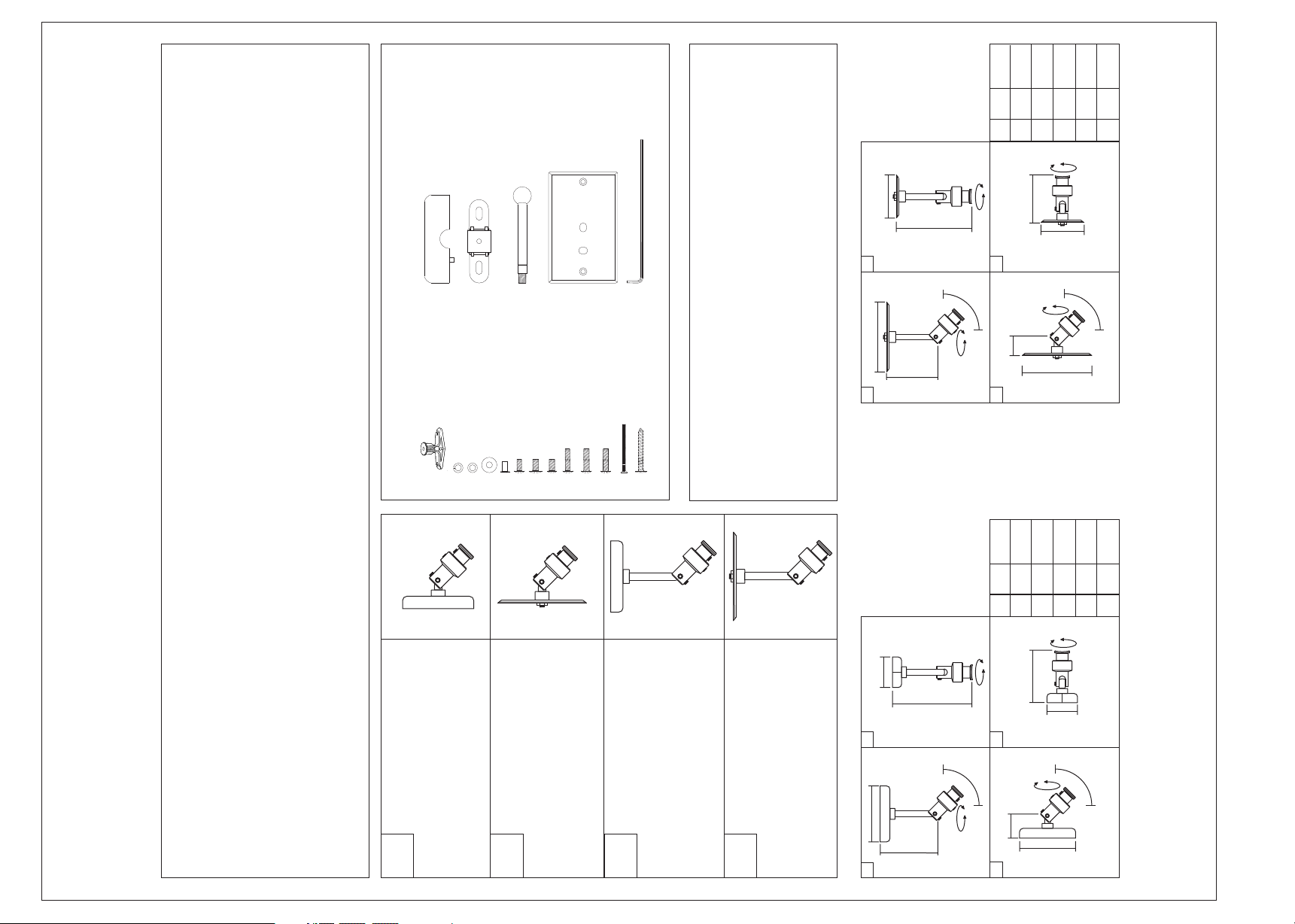
X 1 (Allen Key)
115.0mm
103.0mm
4.05”
4.52”
B
A
30.0mm
1.18”
C
84.0mm
3.30”
D
72.0mm
135.0mm
5.31”
2.83”
F
E
P. 1/4
AM-20
X 2 (Plastic Cover Half)
S
PARTS
X 2 (Drywall Anchors)
X 1 (Split Washer)
X 1 (Dual Point Adapter)
R
X 1 (Small Washer)
K L M
X 2 (Large Washer)
J
X 1 (5mm Key hole Adapter)
I
X 1 (Long Post)
Q
X 1 (5mm x 25mm)
X 2 (1/4-20 x .47”)
X 2 (6mm x 12mm)
X 2 (5mm x 12mm)
X 1 (Electrical Box Plate)
P
X 1 (6mm x 25mm)
O
X 2 (Electrical Box Screw)
X 2 (wood screw)
X 1 (1/4-20 x 1”)
A B C D E F G H
360°
NOTICE!
F
E
2
B
A
1
360°
90°
360°
D
F
4
90°
360°
C
3
B
If you have any questions on the installation, assembly, or
at (865) 671-2020 Monday-Friday 9.30a - 5.30p or by email 24/7
have missing or damaged parts, please contact our support team
93.0mm
92.0mm
35.0mm
87.0mm
50.0mm
140.0mm
3.66”
3.62”
B
A
5.51”
1.37”
3.42”
1.96”
F
E
D
C
UNIVERSAL SPEAKER MOUNT
The AM-20 Speaker Mount has been designed to offer 4 different configurations for mounting home
theater speakers and can be used as a wall or ceiling mount. It is pre assembled in the Standard
Wall Mount Configuration (A) shown, but can be assembled to any of the 3 additional configurations
(B,C,D) shown. Just select the configuration best suited for your application and follow the assembly
instructions on pages 2-4.
The AM-20 can support speakers up to 12 lbs (5.44kg) in all configurations and offers a full tilt
and swivel adjustability.
Configuration
Standard Wall Mount
A
Configuration
Electrical Box Wall Mount
For mounting to a standard single
For mounting to solid wall surfaces
such as wood stud, drywall or
masonry (concrete).
B
gang electrical box located on a
Standard Ceiling Mount
wall in pre-wired homes.
C
Configuration
Configuration
Electrical Box Ceiling Mount
For mounting to a standard single
gang electrical box located on a
For mounting to solid ceiling surfaces
such as wood stud, drywall or
masonry (concrete).
D
ceiling in pre-wired homes.
360°
F
E
2
B
A
1
360°
90°
360°
D
F
4
90°
360°
C
3
B
www.pinpointmounts.com 11157 Outlet Dr. Knoxville TN 37932 (856) 671-2020
REV. 2-9/10
Page 2
14mm
9/16”
14mm
P. 2/4
9/16”
9/16”
14mm
P
P
3
9/16”
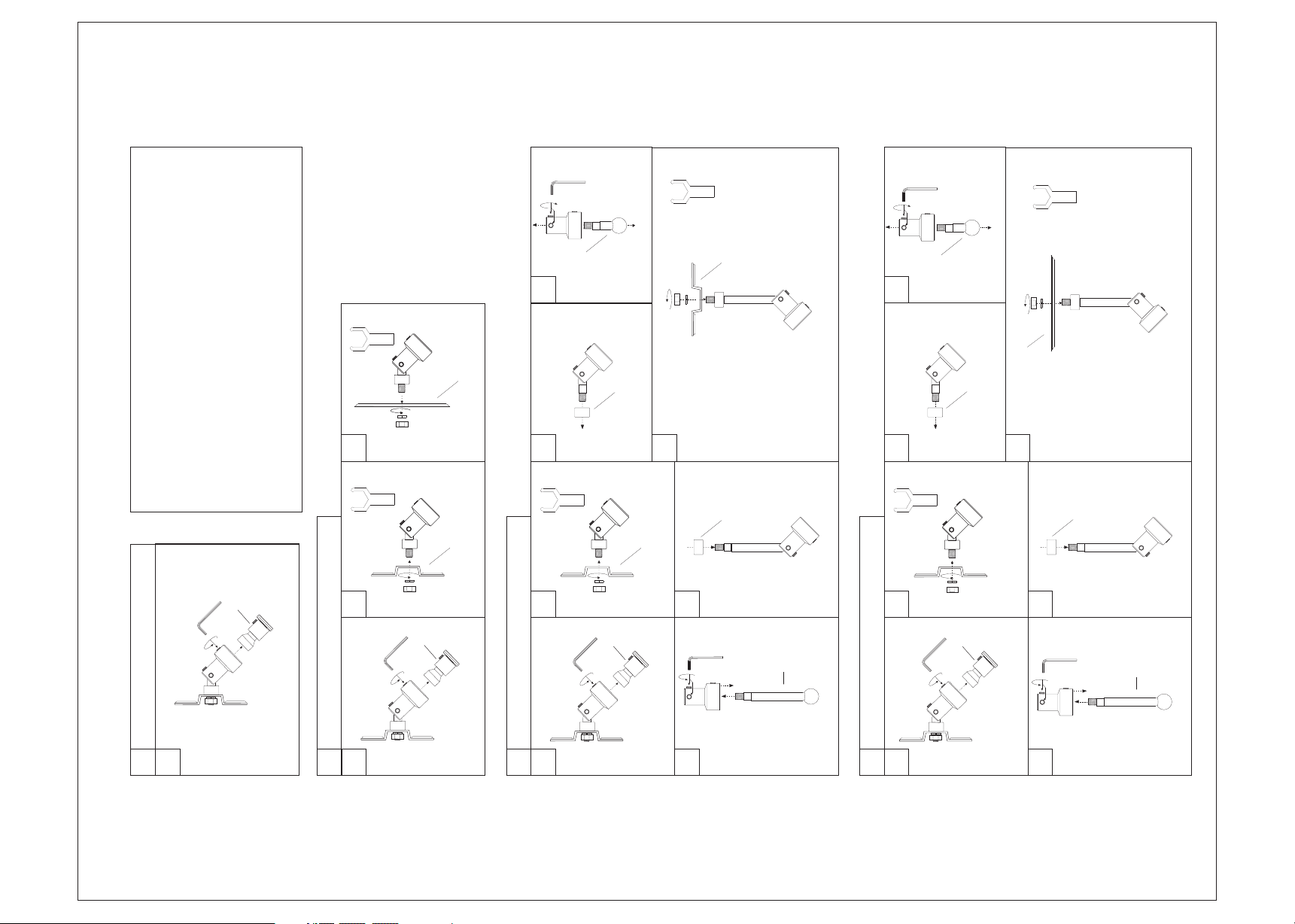
Choose the mounting configuration needed
for your application from the diagrams on
this page then continue to the next page.
Note: Over tightening the set screws may
cause cross threading or stripped threads.
14mm
Attach Adapter Plate(P)
B
A
2
A
D
4
Remove Short Arm(D)
C
3
9/16”
14mm
Remove Support Spacer(C)
7
B
Reattach Mounting Plate(B)
D
4
Remove Short Arm(D)
P
Attach Adapter Plate(P)
C
3
9/16”
14mm
C
Remove Support Spacer(C)
7
C
B
2
A
6
Remove Mounting Plate(B)Remove Mounting Tip(A)
Replace Support Spacer(C)
2
A
Q
6
Remove Mounting Plate(B)
Replace Support Spacer(C)
Q
SPEAKER MOUNT CONFIGURATION ASSEMBLY
STANDARD WALL MOUNT
1
A
Remove Mounting Tip(A)
PRE-WIRED CEILING MOUNT
1
B
STANDARD CEILING MOUNT
Remove Mounting Tip(A) Remove Mounting Plate(B)
1
C
5
PRE-WIRED CEILING MOUNT
Attach Long Arm(Q)
1
D
Remove Mounting Tip(A)
Attach Long Arm(Q)
5
Page 3
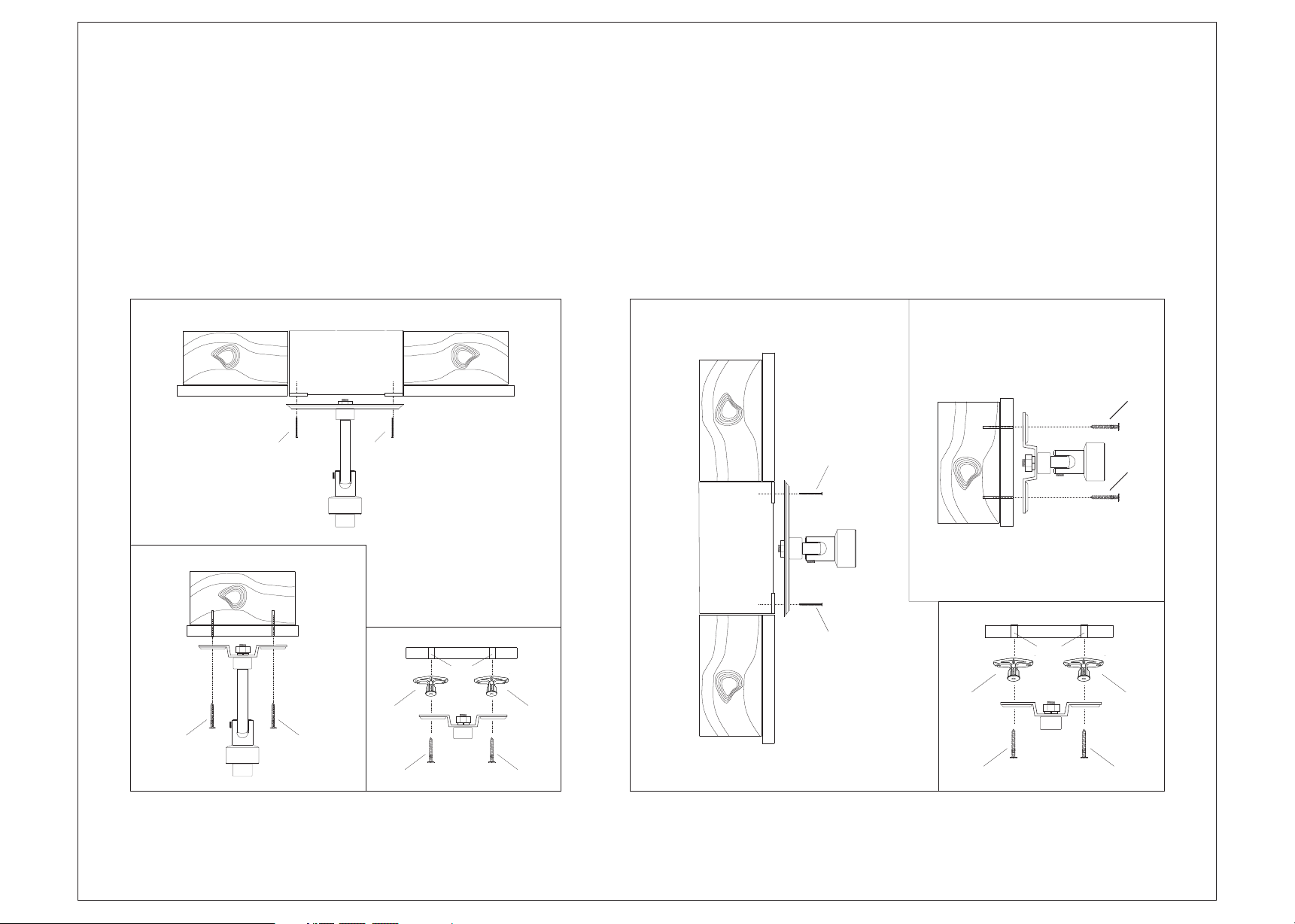
ATTACHING THE MOUNT
A
B1.
MOUNTING TO A CEILING LOCATION
FOLLOW DIAGRAM A WHEN MOUNTING
TO A STANDARD SINGLE GANG
ELECTRICAL BOX.
FOLLOW DIAGRAM B WHEN MOUNTING
TO A SOLID SURFACE LOCATION.
B1. MOUNTING TO WOOD STUD
B2. MOUNTING TO DRYWALL
ELECTRICAL BOX
SINGLE
ELECTRICAL
BOX
B
WOOD STUD
B
A
MOUNTING TO A WALL LOCATION
FOLLOW DIAGRAM A WHEN MOUNTING
TO A STANDARD SINGLE GANG
ELECTRICAL BOX.
FOLLOW DIAGRAM B WHEN MOUNTING
TO A SOLID SURFACE LOCATION.
B1. MOUNTING TO WOOD STUD
B2. MOUNTING TO DRYWALL
ELECTRICAL BOX
SINGLE
ELECTRICAL
BOX
B
B1.
WOOD STUD
A
A
DRY WALL
3/8”
AA
A A
B2.
M M
DRY WALL
3/8”
B
B2.
M M
AA
WARNING! - When mounting this product it is recommended to determine the location selected will support at least two times (2x)
the total weight of the speaker. When mounting this product to a electrical box location, inspect this location to determine if the box
is properly attached to a support stud (2x4’) with screw/nail & the drywall is in good condition.
P. 3/4
Page 4
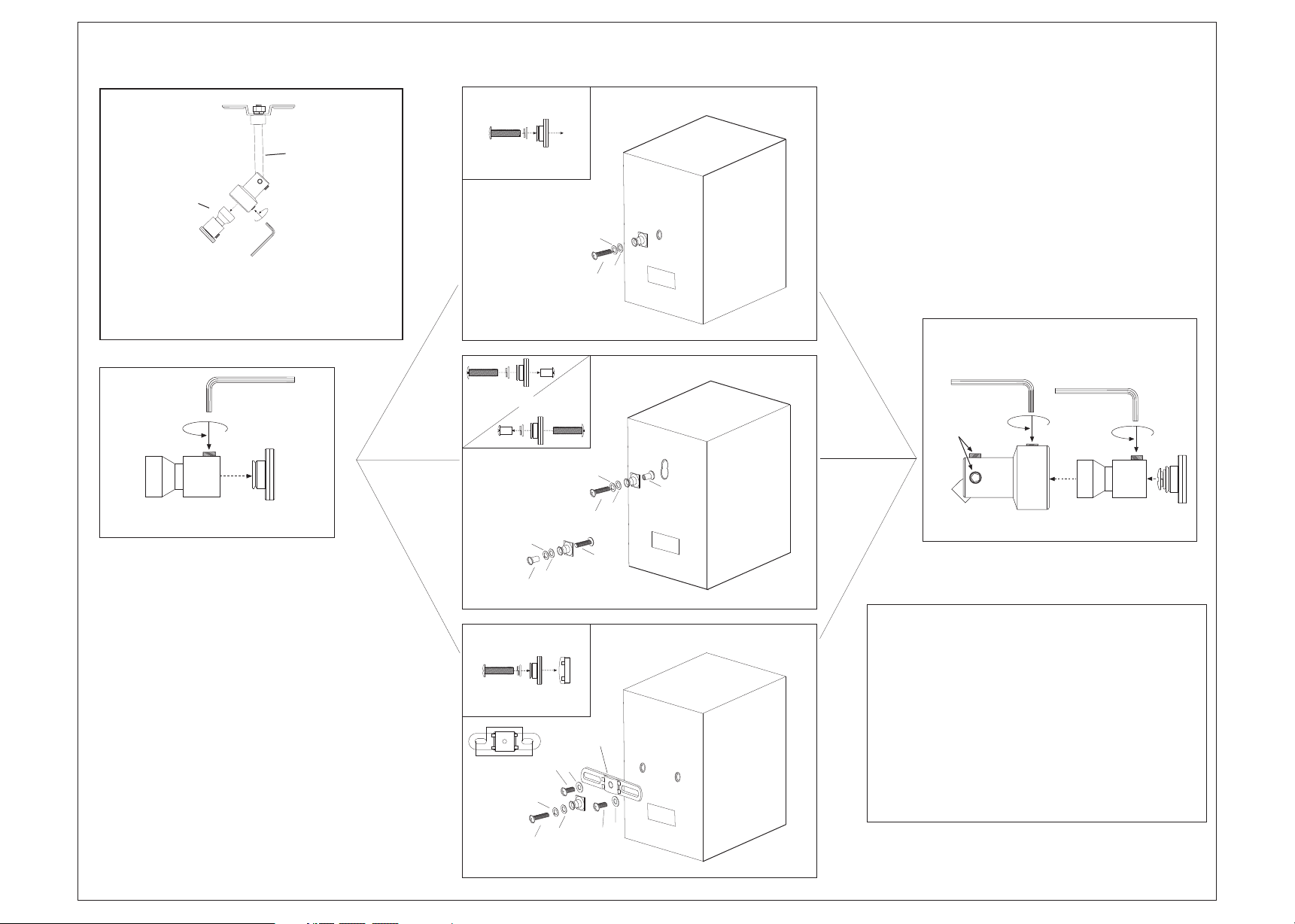
MOUNTING THE SPEAKER
Step 3
SINGLE MOUNTING POINT
Step 1
2
1
Before installing the speaker, remove
the mounting tip assembly(1) from the
mounting bracket body(2).
Step 2
A
B
Step 2
To mount a speaker, remove the single point
adapter tip(A) from the Mounting body(B) and
determine the correct speaker mounting point
your speaker has from the three (3) diagrams
shown in step 3.
-Some speakers may use more than one type
of mounting point, select the one best suited
for your application.
-The hardware kit supplied with this mount are
contains the most common size screws used
to mount speakers. Some speakers may
require longer or shorter screws not supplied
in this kit.
(C,D or E & K,L)
(E,K,L,I)
(D,K,L & R)
1.96” (50mm) Min
2.67” (68mm) Max
or
L
I
F,G or H
L
D
(I,K,L,E)
or
K
J
K
C,D or E
L
E
F,G or H
L
K
KEYHOLE MOUNTING POINT
I
K
E
DUAL MOUNTING POINTS
R
J
Step 4
Once the speaker has been attached
to the adapter tip(A), replace the adapter
tip(A) to the mounting body(B) and then
attach the adapter body(B) to the speaker
mount assembly(C).
Step 4
C1
C
After the speaker has been attached
to the speaker mount assembly, you
should connect the speaker wires.
To aim the speaker, loosen the small
allen key bolts (C1) so that the adapter
body can be rotated & tilted to the
desired position. Tighten the allen key
bolts(C1) to lock the speaker into the
desired position.
AB
P. 4/4
 Loading...