

Page 1

Avid Unity™ MediaNetwork
File Manager Setup Guide
make manage move | media
™
Avid
®
Page 2

Copyright and Disclaimer
Product specifications are subject to change without notice and do not represent a commitment on the part
of Avid Technology, Inc. The software described in this document is furnished under a license agreement.
You can obtain a copy of that license by visiting Avid's Web site at www.avid.com. The terms of that license
are also available in the product in the same directory as the software. The software may not be reverse
assembled and may be used or copied only in accordance with the terms of the license agreement. It is
against the law to copy the software on any medium except as specifically allowed in the license
agreement. Avid products or portions thereof are protected by one or more of the following United States
patents: 4,746,994; 4,970,663; 5,045,940; 5,267,351; 5,309,528; 5,355,450; 5,396,594; 5,440,348;
5,452,378; 5,467,288; 5,513,375; 5,528,310; 5,557,423; 5,568,275; 5,577,190; 5,584,006; 5,640,601;
5,644,364; 5,654,737; 5,715,018; 5,724,605; 5,726,717; 5,729,673; 5,745,637; 5,752,029; 5,754,851;
5,799,150; 5,812,216; 5,852,435; 5,883,670; 5,905,841; 5,929,836; 5,929,942; 5,930,445; 5,946,445;
5,987,501; 5,995,115; 6,016,152; 6,018,337; 6,023,531; 6,035,367; 6,038,573; 6,058,236; 6,061,758;
6,091,778; 6,105,083; 6,118,444; 6,128,001; 6,130,676; 6,134,607; 6,137,919; 6,141,007; 6,141,691;
6,157,929; 6,198,477; 6,201,531; 6,211,869; 6,223,211; 6,239,815; 6,249,280; 6,269,195; 6,301,105;
6,317,158; 6,317,515; 6,327,253; 6,330,369; 6,351,557; 6,353,862; 6,357,047; 6,392,710; 6,404,435;
6,407,775; 6,417,891; 6,426,778; D396,853; D398,912. Additional U.S. and foreign patents pending. No
part of this document may be reproduced or transmitted in any form or by any means, electronic or
mechanical, including photocopying and recording, for any purpose without the express written permission
of Avid Technology, Inc.
Copyright © 2003 Avid Technology, Inc. and its licensors. All rights reserved. Printed in USA.
The following disclaimer is required by Apple Computer, Inc.
APPLE COMPUTER, INC. MAKES NO WARRANTIES WHATSOEVER, EITHER EXPRESS OR IMPLIED,
REGARDING THIS PRODUCT, INCLUDING WARRANTIES WITH RESPECT TO ITS
MERCHANTABILITY OR ITS FITNESS FOR ANY PARTICULAR PURPOSE. THE EXCLUSION OF
IMPLIED WARRANTIES IS NOT PERMITTED BY SOME STATES. THE ABOVE EXCLUSION MAY NOT
APPLY TO YOU. THIS WARRANTY PROVIDES YOU WITH SPECIFIC LEGAL RIGHTS. THERE MAY BE
OTHER RIGHTS THAT YOU MAY HAVE WHICH VARY FROM STATE TO STATE.
The following disclaimer is required by Sam Leffler and Silicon Graphics, Inc. for the use of
their TIFF library:
Copyright © 1988–1997 Sam Leffler
Copyright © 1991–1997 Silicon Graphics, Inc.
Permission to use, copy, modify, distribute, and sell this software [i.e., the TIFF library] and its
documentation for any purpose is hereby granted without fee, provided that (i) the above copyright notices
and this permission notice appear in all copies of the software and related documentation, and (ii) the
names of Sam Leffler and Silicon Graphics may not be used in any advertising or publicity relating to the
software without the specific, prior written permission of Sam Leffler and Silicon Graphics.
THE SOFTWARE IS PROVIDED “AS-IS” AND WITHOUT WARRANTY OF ANY KIND, EXPRESS,
IMPLIED OR OTHERWISE, INCLUDING WITHOUT LIMITATION, ANY WARRANTY OF
MERCHANTABILITY OR FITNESS FOR A PARTICULAR PURPOSE.
IN NO EVENT SHALL SAM LEFFLER OR SILICON GRAPHICS BE LIABLE FOR ANY SPECIAL,
INCIDENTAL, INDIRECT OR CONSEQUENTIAL DAMAGES OF ANY KIND, OR ANY DAMAGES
WHATSOEVER RESULTING FROM LOSS OF USE, DATA OR PROFITS, WHETHER OR NOT ADVISED
OF THE POSSIBILITY OF DAMAGE, AND ON ANY THEORY OF LIABILITY, ARISING OUT OF OR IN
CONNECTION WITH THE USE OR PERFORMANCE OF THIS SOFTWARE.
The following disclaimer is required by the Independent JPEG Group:
Portions of this software are based on work of the Independent JPEG Group.
The following disclaimer is required by Paradigm Matrix:
Portions of this software licensed from Paradigm Matrix.
The following disclaimer is required by Ray Sauers Associates, Inc.:
“Install-It” is licensed from Ray Sauers Associates, Inc. End-User is prohibited from taking any action to
derive a source code equivalent of “Install-It,” including by reverse assembly or reverse compilation, Ray
Sauers Associates, Inc. shall in no event be liable for any damages resulting from reseller’s failure to
perform reseller’s obligation; or any damages arising from use or operation of reseller’s products or the
software; or any other damages, including but not limited to, incidental, direct, indirect, special or
Page 3

consequential Damages including lost profits, or damages resulting from loss of use or inability to use
reseller’s products or the software for any reason including copyright or patent infringement, or lost data,
even if Ray Sauers Associates has been advised, knew or should have known of the possibility of such
damages.
The following disclaimer is required by Videomedia, Inc.:
“Videomedia, Inc. makes no warranties whatsoever, either express or implied, regarding this product,
including warranties with respect to its merchantability or its fitness for any particular purpose.”
“This software contains V-LAN ver. 3.0 Command Protocols which communicate with V-LAN ver. 3.0
products developed by Videomedia, Inc. and V-LAN ver. 3.0 compatible products developed by third parties
under license from Videomedia, Inc. Use of this software will allow “frame accurate” editing control of
applicable videotape recorder decks, videodisc recorders/players and the like.”
The following disclaimer is required by Altura Software, Inc. for the use of its Mac2Win
software and Sample Source Code:
©1993–1998 Altura Software, Inc.
The following disclaimer is required by Ultimatte Corporation:
Certain real-time compositing capabilities are provided under a license of such technology from Ultimatte
Corporation and are subject to copyright protection.
The following disclaimer is required by 3Prong.com Inc.:
Certain waveform and vector monitoring capabilities are provided under a license from 3Prong.com Inc.
Attn. Government User(s). Restricted Rights Legend
U.S. GOVERNMENT RESTRICTED RIGHTS. This Software and its documentation are “commercial
computer software” or “commercial computer software documentation.” In the event that such Software or
documentation is acquired by or on behalf of a unit or agency of the U.S. Government, all rights with
respect to this Software and documentation are subject to the terms of the License Agreement, pursuant to
FAR §12.212(a) and/or DFARS §227.7202-1(a), as applicable.
Trademarks
888 I/O, AirPlay, AirSPACE, AirSPACE HD, AniMatte, AudioSuite, AudioVision, AutoSync, Avid,
AVIDdrive, AVIDdrive Towers, AvidNet, AvidNetwork, AVIDstripe, Avid Unity, Avid Xpress, AVoption,
AVX, CamCutter, ChromaCurve, ChromaWheel, DAE, D-Fi, D-fx, Digidesign, Digidesign Audio Engine,
Digidesign Intelligent Noise Reduction, DigiDrive, DINR, D-Verb, Equinox, ExpertRender, FieldPak,
Film Composer, FilmScribe, FluidMotion, HIIP, HyperSPACE, HyperSPACE HDCAM, IllusionFX,
Image Independence, Intraframe, iS9, iS18, iS23, iS36, Lo-Fi, Magic Mask, make manage move | media,
Marquee, Matador, Maxim, MCXpress, Media Composer, MediaDock, MediaDock Shuttle, Media Fusion,
Media Illusion, MediaLog, Media Reader, Media Recorder, MEDIArray, MediaShare, Meridien, MetaSync,
NaturalMatch, NetReview, NewsCutter, OMF, OMF Interchange, OMM, Open Media Framework,
Open Media Management, ProEncode, Pro Tools, QuietDrive, Recti-Fi, rS9, rS18, Sci-Fi, Softimage,
Sound Designer II, SPACE, SPACEShift, Symphony, Trilligent, UnityRAID, Vari-Fi, Video Slave Driver,
VideoSPACE, and Xdeck are either registered trademarks or trademarks of Avid Technology, Inc. in the
United States and/or other countries.
iNEWS, iNEWS ControlAir, and Media Browse are trademarks of iNews, LLC.
Asanté and FriendlyNET are registered trademarks; IntraCore is a trademark of Asanté Technologies, Inc.
ATTO is a trademark of ATTO Technology, Inc. Ghost is a registered trademark of Symantec Corporation
in the United States and other countries. Hyperterminal is a registered trademark of Hilgraveve, Inc.
Macintosh is a trademark of Apple Computer, Inc., registered in the U.S. and other countries. Microsoft,
Windows, and Windows NT are either registered trademarks or trademarks of Microsoft Corporation in the
United States and/or other countries. SAN InSite is a trademark of Vixel Corporation. ScheduALL is a
trademark of VizuALL, Inc.
Avid Unity MediaNetwork File Manager Setup Guide • Part 0130-05488-01 Rev. A •
February 2003
Page 4

Page 5

Contents
Using This Guide . . . . . . . . . . . . . . . . . . . . . . . . . . . . . . . . . . . . 11
Who Should Use This Guide . . . . . . . . . . . . . . . . . . . . . . . . . . . . . . . . . 12
About This Guide . . . . . . . . . . . . . . . . . . . . . . . . . . . . . . . . . . . . . . . . . . 12
Symbols and Conventions . . . . . . . . . . . . . . . . . . . . . . . . . . . . . . . . . . . 13
If You Need Help . . . . . . . . . . . . . . . . . . . . . . . . . . . . . . . . . . . . . . . . . . 15
If You Have Documentation Comments . . . . . . . . . . . . . . . . . . . . . . . . . 15
How to Order Documentation. . . . . . . . . . . . . . . . . . . . . . . . . . . . . . . . . 16
Related Information . . . . . . . . . . . . . . . . . . . . . . . . . . . . . . . . . . . . . . . . 16
Avid Educational Services . . . . . . . . . . . . . . . . . . . . . . . . . . . . . . . . . . . 17
Chapter 1 Preinstallation Overview . . . . . . . . . . . . . . . . . . . . . . . . . . . . . . 19
Before You Begin . . . . . . . . . . . . . . . . . . . . . . . . . . . . . . . . . . . . . . . . . . 19
MediaNetwork and Trilligent Cluster Components . . . . . . . . . . . . . . . . . 20
Storage Subsystem . . . . . . . . . . . . . . . . . . . . . . . . . . . . . . . . . . . . . 21
Media Server Subsystem for a Trilligent Cluster . . . . . . . . . . . . . . . 21
File Manager Failover Configurations. . . . . . . . . . . . . . . . . . . . . . . . . . . 22
Component Layout Recommendations . . . . . . . . . . . . . . . . . . . . . . . . . 22
Single-Rack Layout . . . . . . . . . . . . . . . . . . . . . . . . . . . . . . . . . . . . . 23
Multiple-Rack Layout . . . . . . . . . . . . . . . . . . . . . . . . . . . . . . . . . . . . 23
Chapter 2 Installing the MediaNetwork Storage Subsystem
Hardware . . . . . . . . . . . . . . . . . . . . . . . . . . . . . . . . . . . . . . . . . 25
Installing Rack-Mount Rails and Brackets . . . . . . . . . . . . . . . . . . . . . . . 25
Installing File Managers and Storage Subsystem Components. . . . . . . 26
Uninterruptible Power Sources . . . . . . . . . . . . . . . . . . . . . . . . . . . . 26
Installing the MEDIArray II Drive Enclosures . . . . . . . . . . . . . . . . . . 27
Installing the MEDIArray II Drive Enclosure Rack-Mount
Rails . . . . . . . . . . . . . . . . . . . . . . . . . . . . . . . . . . . . . . . . . . . . 27
Mounting the MEDIArray II Drive Enclosure . . . . . . . . . . . . . . . 28
Installing the MEDIArray II Drives . . . . . . . . . . . . . . . . . . . . . . . 29
Page 6

Connecting the MEDIArray II Drive Enclosure Power
Cords . . . . . . . . . . . . . . . . . . . . . . . . . . . . . . . . . . . . . . . . . . . 31
Setting the MEDIArray II Drive Enclosure IDs . . . . . . . . . . . . . . 32
Installing a Standard Keyboard, Monitor, and Mouse. . . . . . . . . . . . 33
Installing the Shelf . . . . . . . . . . . . . . . . . . . . . . . . . . . . . . . . . . . 33
Installing the Monitor . . . . . . . . . . . . . . . . . . . . . . . . . . . . . . . . . 33
Connecting the Monitor Power Cord . . . . . . . . . . . . . . . . . . . . . 33
Installing the Keyboard, Monitor, and Mouse (KMM) Assembly. . . . 34
Installing the KMM Rack-Mount Rails . . . . . . . . . . . . . . . . . . . . 34
Mounting the KMM . . . . . . . . . . . . . . . . . . . . . . . . . . . . . . . . . . . 34
Connecting the KMM Power Cord . . . . . . . . . . . . . . . . . . . . . . . 35
Installing the MEDIASwitch . . . . . . . . . . . . . . . . . . . . . . . . . . . . . . . 35
Installing the MEDIASwitch Rack-Mount Rails. . . . . . . . . . . . . . 35
Mounting the MEDIASwitch . . . . . . . . . . . . . . . . . . . . . . . . . . . . 35
MEDIASwitch Port Requirements . . . . . . . . . . . . . . . . . . . . . . . 36
Installing an SFP Connector . . . . . . . . . . . . . . . . . . . . . . . . . . . 37
Connecting the MEDIASwitch Power Cord . . . . . . . . . . . . . . . . 38
Installing the KVM Switch . . . . . . . . . . . . . . . . . . . . . . . . . . . . . . . . . 38
Installing the KVM Switch Rack-Mount Bracket . . . . . . . . . . . . . 38
Mounting the KVM Switch . . . . . . . . . . . . . . . . . . . . . . . . . . . . . 38
Connecting the KVM Power Cord . . . . . . . . . . . . . . . . . . . . . . . 39
Installing the File Manager . . . . . . . . . . . . . . . . . . . . . . . . . . . . . . . . 39
Installing the File Manager Rack-Mount Rails . . . . . . . . . . . . . . 40
Mounting the File Manager . . . . . . . . . . . . . . . . . . . . . . . . . . . . 40
Connecting the File Manager Power Cord . . . . . . . . . . . . . . . . . 40
Installing the Failover File Manager . . . . . . . . . . . . . . . . . . . . . . . . . 41
Installing the Ethernet Hub . . . . . . . . . . . . . . . . . . . . . . . . . . . . . . . . 41
Installing the Rack-Mount Bracket . . . . . . . . . . . . . . . . . . . . . . . 41
Mounting the Ethernet Hub . . . . . . . . . . . . . . . . . . . . . . . . . . . . 41
Connecting the Ethernet Hub Power Cord. . . . . . . . . . . . . . . . . 42
6
Page 7

Connecting the File Manager and Storage. . . . . . . . . . . . . . . . . . . . . . . 42
Connecting a Standard Keyboard, Monitor, and Mouse to the
File Manager. . . . . . . . . . . . . . . . . . . . . . . . . . . . . . . . . . . . . . . . . 42
Connecting a Standard Keyboard, Monitor, and Mouse to the
KVM . . . . . . . . . . . . . . . . . . . . . . . . . . . . . . . . . . . . . . . . . . . . . . . 43
Connecting the KMM to the KVM (Option). . . . . . . . . . . . . . . . . . . . 43
Connecting the File Manager to the KVM (Option) . . . . . . . . . . . . . 44
Connecting the Failover File Manager to the KVM . . . . . . . . . . . . . 45
Connecting the File Manager to the MEDIASwitch . . . . . . . . . . . . . 45
Connecting the Failover File Manager to the MEDIASwitch . . . . . . 46
Connecting the MEDIASwitch Serial Port to the File Manager
for Initial Switch Configuration . . . . . . . . . . . . . . . . . . . . . . . . . . . 46
Connecting the MEDIArray II Drive Enclosure to the
MEDIASwitch . . . . . . . . . . . . . . . . . . . . . . . . . . . . . . . . . . . . . . . . 47
Connecting One MEDIArray II Drive Enclosure. . . . . . . . . . . . . 48
Connecting a Daisy Chain of Two MEDIArray II Drive
Enclosures . . . . . . . . . . . . . . . . . . . . . . . . . . . . . . . . . . . . . . . 50
Connecting to Two MEDIASwitches . . . . . . . . . . . . . . . . . . . . . 52
Connecting the Ethernet Switch in a MediaNetwork System. . . . . . 53
Connecting the File Manager to the Ethernet Switch. . . . . . . . . . . . 54
Connecting the Failover File Manager to the Ethernet Switch. . . . . 54
Connecting the MEDIASwitch to the Ethernet Switch . . . . . . . . . . . 54
Cross-Connecting the File Managers in a Failover
Configuration . . . . . . . . . . . . . . . . . . . . . . . . . . . . . . . . . . . . . . . . 55
Chapter 3 Configuring the MEDIASwitches . . . . . . . . . . . . . . . . . . . . . . . 57
Changing the MEDIASwitch IP Address. . . . . . . . . . . . . . . . . . . . . . . . . 57
Installing the SAN InSite Professional Software. . . . . . . . . . . . . . . . . . . 59
Configuring the MEDIASwitch . . . . . . . . . . . . . . . . . . . . . . . . . . . . . . . . 61
Copying the MEDIASwitch Files into the SAN InSite Folder . . . . . . 61
Adding the MEDIASwitch Address to the hosts File . . . . . . . . . . . . 62
Establishing a Connection to the MEDIASwitch . . . . . . . . . . . . . . . 62
Setting the MEDIASwitch Configuration . . . . . . . . . . . . . . . . . . . . . 63
Starting the SAN InSite Server Manually . . . . . . . . . . . . . . . . . . . . . . . . 64
Using the SAN InSite Client . . . . . . . . . . . . . . . . . . . . . . . . . . . . . . . . . . 65
7
Page 8

Chapter 4 Configuring the File Manager . . . . . . . . . . . . . . . . . . . . . . . . . . 67
Setting Up the File Manager . . . . . . . . . . . . . . . . . . . . . . . . . . . . . . . . . . 67
Checking the Operating System Installation. . . . . . . . . . . . . . . . . . . 68
Setting the Date, Time, Time Zone, and Daylight Saving
Time Option. . . . . . . . . . . . . . . . . . . . . . . . . . . . . . . . . . . . . . . . . . 69
Setting the Paging File Size . . . . . . . . . . . . . . . . . . . . . . . . . . . . . . . 70
Configuring Network Properties . . . . . . . . . . . . . . . . . . . . . . . . . . . . 71
Configuring System Properties. . . . . . . . . . . . . . . . . . . . . . . . . . . . . 72
Configuring the Failover File Manager . . . . . . . . . . . . . . . . . . . . . . . . . . 72
Configuring Network Properties for File Managers in a Failover
Configuration . . . . . . . . . . . . . . . . . . . . . . . . . . . . . . . . . . . . . . . . . 73
Setting Up the IP Addresses . . . . . . . . . . . . . . . . . . . . . . . . . . . 74
Chapter 5 MediaNetwork File Manager Software Setup . . . . . . . . . . . . . 77
Installing the MediaNetwork File Manager Software. . . . . . . . . . . . . . . . 77
Configuring the MediaNetwork File Manager Software. . . . . . . . . . . . . . 79
Avid Billing Application Information . . . . . . . . . . . . . . . . . . . . . . . . . . . . . 79
Chapter 6 Trilligent File Manager Software Setup . . . . . . . . . . . . . . . . . . 81
Installing the Trilligent Cluster File Manager Software . . . . . . . . . . . . . . 81
Configuring the MediaNetwork Software. . . . . . . . . . . . . . . . . . . . . . . . . 83
Avid Billing Application Information . . . . . . . . . . . . . . . . . . . . . . . . . . . . . 83
Appendix A File Manager and Storage Specifications . . . . . . . . . . . . . . . . 85
Dimensions and Weight . . . . . . . . . . . . . . . . . . . . . . . . . . . . . . . . . . . . . 85
Environmental Specifications . . . . . . . . . . . . . . . . . . . . . . . . . . . . . . . . . 86
Electrical Specifications . . . . . . . . . . . . . . . . . . . . . . . . . . . . . . . . . . . . . 87
Power Cords . . . . . . . . . . . . . . . . . . . . . . . . . . . . . . . . . . . . . . . . . . . . . . 88
UPS Power Cord . . . . . . . . . . . . . . . . . . . . . . . . . . . . . . . . . . . . . . . 89
Appendix B Installing UPS Monitoring Software. . . . . . . . . . . . . . . . . . . . . 91
Installing the Serial Cable . . . . . . . . . . . . . . . . . . . . . . . . . . . . . . . . . . . . 92
Installing the CheckUPS II Advanced Software . . . . . . . . . . . . . . . . . . . 92
Configuring the CheckUPS II Software . . . . . . . . . . . . . . . . . . . . . . . . . . 93
8
Page 9

Appendix C Installing the MediaNetwork Billing Software . . . . . . . . . . . . . 97
Installing the Billing Server Software . . . . . . . . . . . . . . . . . . . . . . . . . . . 99
Configuring the Billing Server Software . . . . . . . . . . . . . . . . . . . . . . . . . 99
Installing the Billing Client Software . . . . . . . . . . . . . . . . . . . . . . . . . . . 100
Configuring the Billing Client Software . . . . . . . . . . . . . . . . . . . . . . . . . 101
Appendix D Using the Product Recovery CD-ROM . . . . . . . . . . . . . . . . . . 103
Reinstalling the Windows NT Operating System . . . . . . . . . . . . . . . . . 104
Configuring the File Manager Using Windows NT Setup . . . . . . . . . . . 106
Checking the Drivers . . . . . . . . . . . . . . . . . . . . . . . . . . . . . . . . . . . . . . 108
Updating the ATTO Driver and Phantom Device . . . . . . . . . . . . . . . . . 109
Updating the ATTO Fibre Channel Driver . . . . . . . . . . . . . . . . . . . 109
Updating the ATTO Phantom Device. . . . . . . . . . . . . . . . . . . . . . . 110
Reinstalling the MediaNetwork Software . . . . . . . . . . . . . . . . . . . . . . . 112
Appendix E File Manager Troubleshooting . . . . . . . . . . . . . . . . . . . . . . . . 113
Appendix F Regulatory and Safety Notices . . . . . . . . . . . . . . . . . . . . . . . . 115
FCC Notice. . . . . . . . . . . . . . . . . . . . . . . . . . . . . . . . . . . . . . . . . . . . . . 115
Canadian ICES-003 . . . . . . . . . . . . . . . . . . . . . . . . . . . . . . . . . . . . . . . 116
European Union Notice . . . . . . . . . . . . . . . . . . . . . . . . . . . . . . . . . . . . 116
Australia and New Zealand EMC Regulations . . . . . . . . . . . . . . . . . . . 118
Taiwan EMC Regulations. . . . . . . . . . . . . . . . . . . . . . . . . . . . . . . . . . . 119
9
Page 10

10
Page 11

Using This Guide
n
Congratulations on your purchase of an Avid Unity™ MediaNetwork
workgroup or Trilligent
workgroup to share media files and other project data among a maximum
of 24 Fibre Channel attached clients and 60 Ethernet clients across
4 PortServer Pro systems.
For other possible Ethernet client configurations, contact Avid Technology
Product Marketing.
These editing products are supported by Avid Unity MediaNetwork
workgroups and Trilligent Clusters.
®
Macintosh
Media Station XL, Avid Xpress
Windows
Film Composer, Avid Xpress for Windows NT
NewsCutter
A Trilligent Cluster allows you to connect up to 20 Trilligent Media
Servers to deliver streaming media and other high-bandwidth content over
the Internet.
clients — Media Composer®, Film Composer®,
®
clients — Avid® Symphony™, Media Composer,
®
, and NewsCutter XP systems
™
Cluster. You can use your MediaNetwork
®
, and Pro Tools® for Macintosh® systems
®
or Windows 2000,
n
Your MediaNetwork workgroup or Trilligent Cluster might not contain all
the components or features described in the documentation.
Page 12

Using This Guide
Who Should Use This Guide
This guide is intended for personnel responsible for installing, configuring,
or maintaining a MediaNetwork workgroup or Trilligent Cluster. It
provides installation and configuration information specific to the
MediaNetwork and Trilligent hardware and software.
About This Guide
This guide provides task-oriented instructions for setting up a
MediaNetwork workgroup with a Trilligent Cluster.
The Contents lists all topics included in this book. They are presented with
the following overall structure:
• Chapter 1, “Preinstallation Overview,” provides information on the
components, unpacking, rack layout, and network connection
necessary to complete the installation and configuration of the
MediaNetwork environment.
12
• Chapter 2, “Installing the MediaNetwork Storage Subsystem
Hardware,” provides step-by-step instructions for connecting the File
Manager and storage subsystem hardware.
• Chapter 3, “Configuring the MEDIASwitches,” provides step-by-step
instructions for configuring and installing the necessary software for
the MEDIASwitches.
• Chapter 4, “Configuring the File Manager,” provides step-by-step
instructions for configuring the MediaNetwork or Trilligent Cluster
File Managers.
• Chapter 5, “MediaNetwork File Manager Software Setup,” provides
step-by-step instructions for installing the necessary software for the
MediaNetwork File Managers.
• Chapter 6, “Trilligent File Manager Software Setup,” provides stepby-step instructions for installing the necessary software for the
Trilligent File Managers.
Page 13

Symbols and Conventions
• Appendix A, “File Manager and Storage Specifications,” lists th e
dimensions and weight, and the environmental, electrical, and power
cord specifications for the components that are part of a
MediaNetwork workgroup and Trilligent Cluster environment.
• Appendix B, “Installing UPS Monitoring Software,” provides
information for installing and configuring the UPS monitoring
software on the File Manager.
• Appendix C, “Installing the MediaNetwork Billing Software,”
provides information to install the MediaNetwork billing software.
• Appendix D, “Using the Product Recovery CD-ROM,” provides
information you might need to reinstall the Windows NT operating
system on your File Manager.
• Appendix E, “File Manager Troubleshooting,” provides basic
troubleshooting techniques not found in the Avid Unity MediaNetwork
Troubleshooting Guide.
• Appendix F, “Regulatory and Safety Notices,” lists regulatory and
safety notices for the MediaNetwork and Trilligent hardware.
n
You’ll also need the Avid Unity MediaNetwork Management Guide to
create a file system, to create allocation groups and workspaces for media
files, and to create a system user account.
Symbols and Conventions
Avid documentation uses the following symbols and conventions:
Symbol or Convention Meaning or Action
n
c
A note provides important related information,
reminders, recommendations, and strong
suggestions.
A caution means that a specific action you take could
cause harm to your computer or cause you to lose
data.
13
Page 14

Using This Guide
Symbol or Convention Meaning or Action
w
> This symbol indicates menu commands (and
t
k This symbol represents the Apple or Command key.
Margin tips In the margin, you will find tips that help you
Italic font Italic font is used to emphasize certain words and to
Courier Bold font
A warning describes an action that could cause you
physical harm. Follow the guidelines in this
document or on the unit itself when handling
electrical equipment.
subcommands) in the order you select them. For
example, File > Import means to open the File menu
and then select the Import command.
This symbol indicates a single-step procedure.
Multiple arrows in a list indicate that you perform
one of the actions listed.
Press and hold the Command key and another key to
perform a keyboard shortcut.
perform tasks more easily and efficiently.
indicate variables.
Courier Bold font identifies text that you type.
14
Click Quickly press and release the left mouse button
(Windows) or the mouse button (Macintosh).
Double-click Click the left mouse button (Windows) or the mouse
button (Macintosh) twice rapidly.
Right-click Quickly press and release the right mouse button
(Windows only).
Drag Press and hold the left mouse button (Windows) or
the mouse button (Macintosh) while you move the
mouse.
Ctrl+key
k+key
Press and hold the first key while you press the
second key.
Page 15

If You Need Help
If you are having trouble using your MediaNetwork workgroup or
Trilligent Cluster:
1. Retry the action, carefully following the instructions given for that task
in this guide. It is especially important to check each step of your
workflow.
2. Check the release notes supplied with your Avid application for the
latest information that might have become available after the hardcopy
documentation was printed.
3. Check the documentation that came with your Avid application or
your hardware for maintenance or hardware-related issues.
4. Visit the online Knowledge Center at www.avid.com/support. Online
services are available 24 hours per day, 7 days per week. Search this
online Knowledge Center to find answers, to view error messages, to
access troubleshooting tips, to download updates, and to read/join
online message-board discussions.
If You Need Help
5. For Technical Support, please call 800-800-AVID (800-800-2843).
For Broadcast On-Air Sites and Call Letter Stations, call
800-NEWSDNG (800-639-7364).
If You Have Documentation Comments
Avid Technology continuously seeks to improve its documentation. We
value your comments about this guide and other Avid-supplied
documentation.
Simply e-mail your documentation comments to Avid Technology at
TechPubs@avid.com
Please include the title of the document, its part number, revision, and the
specific section you are commenting on in all correspondence.
15
Page 16

Using This Guide
How to Order Documentation
To order additional copies of this documentation from within the
United States, call Avid Sales at 800-949-AVID (800-949-2843). If you
are placing an order from outside the United States, contact your local
Avid representative.
Related Information
The following documents provide more information about the
MediaNetwork workgroup, the MediaNetwork client, and other storage
options:
• Avid Unity MediaNetwork Site Preparation Guide
• Avid Unity MediaNetwork Upgrade Notes
• Avid Unity MediaNetwork System Overview
• Avid Unity MediaNetwork Management Guide
16
• Avid Unity MediaNetwork Troubleshooting Guide
• Avid Unity MediaNetwork Macintosh Fibre Channel Client
Setup Guide
• MediaNetwork Macintosh Fibre Channel Client Quick Start Card
• Avid Unity MediaNetwork Windows Fibre Channel Client Setup Guide
• MediaNetwork Windows Fibre Channel Client Quick Start Card
• Avid Unity MediaNetwork PortServer Setup Guide
• Avid Unity MediaNetwork Macintosh Ethernet Client Setup Guide
• MediaNetwork Macintosh Ethernet Client Quick Start Card
• Avid Unity MediaNetwork Windows Ethernet Client Setup Guide
• MediaNetwork Windows Ethernet Client Quick Start Card
• Avid Unity MediaNetwork Supported Configurations
• Avid Unity MediaNetwork Release Notes
Page 17

Avid Educational Services
For information on courses/schedules, training centers, certifications,
courseware, and books, please visit www.avid.com/training or call
Avid Sales at 800-949-AVID (800-949-2843).
Avid Educational Services
17
Page 18

Using This Guide
18
Page 19

Chapter 1
Preinstallation Overview
This chapter provides preliminary instructions before you install and
configure the MediaNetwork Storage workgroup and Trilligent Cluster
components.
Before You Begin
Keep the shipping
boxes that come with
your MediaNetwork
environment. You
might need to
repackage and ship the
components in the
future.
Before you begin to install the File Manager and storage, do the following:
• Unpack all the components.
• Check the contents of each kit against the list shipped with the order to
confirm you have received all the components.
• Examine all the components for damage, and contact Avid Customer
Support if you notice any problems.
• Obtain a dedicated (static) IP address and host name for each of the
following components in your MediaNetwork and Trilligent Cluster
environment:
- File Manager
- Backup File Manager, if you have a failover configuration
- MEDIASwitch — 2 maximum
- MediaNetwork Fibre attached client — 24 maximum
- PortServer
- MediaNetwork Ethernet client — 60 maximum
Page 20

Chapter 1 Preinstallation Overview
- Trilligent — Media Server — 20 maximum
- Trilligent — Network-routing switch
- Trilligent — Load-balancing network switch
- Trilligent — If you have a load-balancing network switch, a
virtual IP address for the cluster
Alternatively, you can use the nonrouting IP addresses presented
throughout this manual to configure the network for the File Manager
and MEDIASwitches.
n
Trilligent Customer Support supplies the IP addresses to you (based on
your input) on a Configuration Sheet.
MediaNetwork and Trilligent Cluster Components
A MediaNetwork workgroup allows you to connect the latest in shared
storage environments to your Avid workstations. The shared storage lets
you set up a collaborative user environment where several editors can
work on a project at the same time using the same video and audio files.
The Trilligent Cluster is a streaming media environment that consists of
the Trilligent Storage subsystem and the Trilligent Media Server
subsystem. The following sections describe the components that make up
each of these subsystems.
The MediaNetwork and Trilligent components are ready to mount in any
standard 19-inch NEMA or EIA rack. The racks are used to mount the File
Manager, storage, MEDIASwitch, Media Servers, network switches,
uninterruptible power supplies (UPSs), and other components.
20
Page 21

Storage Subsystem
The storage subsystem provides high-capacity, expandable Fibre Channel
shared storage and consists of:
• One to eight rack-mount MEDIArray
MediaNetwork and Trilligent Cluster Components
™
II drive enclosures
n
n
Avid supports a maximum of 100 drives in a drive set. Eight MEDIArray II
drive enclosures allow the maximum number of data drives. Raw state
drives can fill any unpopulated drive slots in the drive enclosure.
• (Option) Computer rack
• (Option) One or more UPSs
• One or two rack-mount MEDIASwitches (8-port or 16-port)
• One or two rack-mount File Managers.
For more information about failover configurations with two File
Managers, see “File Manager Failover Configurations” on page 22.
• One standard keyboard, monitor, and mouse, or one optional pull-out
keyboard, monitor, and mouse (KMM) assembly
• Optional rack-mount keyboard, video, and mouse (KVM) switch
• (Trilligent Option) — One 10BASE-T/100BASE-T Ethernet hub
Media Server Subsystem for a Trilligent Cluster
The Trilligent Cluster Media Server subsystem provides high-throughput
media streaming capabilities and consists of:
n
• One to twenty Media Servers
• One 100BASE-T or Gigabit Ethernet load-balancing network switch
• One 100BASE-T or Gigabit Ethernet network-routing switch
Avid does not supply all the Media Server subsystem components for your
installation. You must provide one or more of the components yourself.
21
Page 22

Chapter 1 Preinstallation Overview
When you are expanding an existing MediaNetwork workgroup or
Trilligent Cluster, you can order MEDIArray II drive enclosures and
Media Servers separately. You can add them to the existing environment,
provided you do not exceed the environmental limits. For information on
environmental limits, see “Component Layout Recommendations” on
page 22.
File Manager Failover Configurations
If properly configured with a redundant File Manager, the MediaNetwork
workgroup or Trilligent Cluster supports automatic failover to a backup
(Failover) File Manager if the active (Primary) File Manager fails. This
ensures that the File Manager is not a single point of failure in your
environment.
Communication through the first three drives in the drive set, as well as
polling over two cross-connected Ethernet paths, ensures that any lack of
response from the initially active File Manager occurs because it has gone
offline. The problem is not due to a failure of the network connections
between the two File Managers.
n
In a failover configuration, neither File Manager is assigned to a primary
or backup role — the first system to come online becomes the Active File
Manager and the second to come online becomes the Failover File
Manager. If both systems come online at the same time, the active role is
negotiated arbitrarily between the two File Managers. For this reason,
Avid recommends that you physically label and refer to your first and
second File Managers as FM1 and FM2 (or use a similar convention).
Component Layout Recommendations
You can install MediaNetwork workgroup or Trilligent Cluster
components either into a single rack or into multiple racks (two or three
racks, depending on the configuration). You can also place the network
switches in their own rack. Plan the rack layout using the general
guidelines in the following sections.
22
Page 23

Single-Rack Layout
Use the following guidelines to determine your single-rack layout:
• Install the pull-out KMM assembly approximately 40 inches
• Install the heaviest components (UPSs and drive enclosures) at the
• Install the MEDIASwitches above the KMM.
• Install the KVM switch above the MEDIASwitches.
• Trilligent — Install the Media Servers above the KVM.
• Install the File Managers above the Media Servers.
• Install the servers for other Avid-integrated applications above the File
Component Layout Recommendations
(1.016 meters) from the floor.
bottom of the rack:
- Five to six drive enclosures with no UPSs
- Three to four drive enclosures with one UPS
Managers.
• Trilligent — Install the load-balancing network switch at the top of the
rack.
Multiple-Rack Layout
Use the following guidelines to determine your multiple-rack layout:
• Install up to eight drive enclosures in one rack.
• Install the pull-out KMM assembly approximately 40 inches
(1.016 meters) from the floor in the second rack.
• Trilligent — Install the Media Servers in the lower portion of the next
rack (maximum of 20 Media Servers requiring 2 U of rack space
each).
• Install the MEDIASwitches above the KMM.
• Install the KVM switch above the KMM.
• Install the active File Manager and the backup File Manager at the
bottom of the second rack.
23
Page 24

Chapter 1 Preinstallation Overview
• Install the servers for other Avid-integrated applications above the File
Managers.
• Trilligent — Install the load-balancing network switch at the top of the
rack.
• Trilligent — If included, install the network-routing switch (layer 2)
below the load-balancing network switch.
24
Page 25

Chapter 2
Installing the MediaNetwork Storage Subsystem Hardware
This chapter describes how to install and connect the File Managers and
other MediaNetwork workgroup hardware.
c
Before you start the procedures in this chapter, you should be familiar
with the preinstallation information in Chapter 1.
Installing Rack-Mount Rails and Brackets
All MediaNetwork rack-mount components are supplied with either
mounting rails or brackets. You should follow the manufacturer’s
installation instructions supplied with each component to correctly attach
the rails or brackets to the rack rails.
n
Where necessary, this guide supplies specific rack-mount rail or bracket
installation instructions. These instructions supersede the manufacturer’s
instructions.
Page 26

Chapter 2 Installing the MediaNetwork Storage Subsystem Hardware
Installing File Managers and Storage Subsystem Components
The File Managers and storage are placed into a rack for easy access to the
cables, connectors, and drives. The following sections describe how to
install the various components into the rack from bottom to top.
Uninterruptible Power Sources
Avid recommends that you use an uninterruptible power source to protect
the data in your MediaNetwork workgroup. You should have an adequate
uninterruptible power source to support these items:
• File Manager
• Failover File Manager
• MEDIArray II drive enclosures
• MEDIASwitches
26
• KMM assembly
• KVM switch
The uninterruptible power source can be conditioned power for your
computer room or several UPSs. If you choose UPSs, you can acquire
them yourself or purchase them from Avid. Avid supplies the Best Power
Fortress 2250 UPS with CheckUPS
You should also use power-monitoring software to control the UPSs and to
shut down the File Managers properly if an extended power outage occurs.
This helps to protect the integrity of your data.
If your environment uses conditioned power for your computer room,
continue with “Installing the MEDIArray II Drive Enclosures” on page 27.
If your environment uses UPSs, see Appendix B before continuing with
“Installing the MEDIArray II Drive Enclosures” on page 27.
II software.
Page 27
Installing File Managers and Storage Subsystem Components
Installing the MEDIArray II Drive Enclosures
The MEDIArray II drive enclosures hold the MEDIArray II drives. Install
the drive enclosures starting at the bottom of the rack.
Installing the MEDIArray II Drive Enclosure Rack-Mount Rails
You can install the rack-mount MEDIArray II drive enclosure in either a
NEMA or an EIA rack. Follow the instructions supplied with the drive
enclosure to install the rack-mount rails, ensuring that:
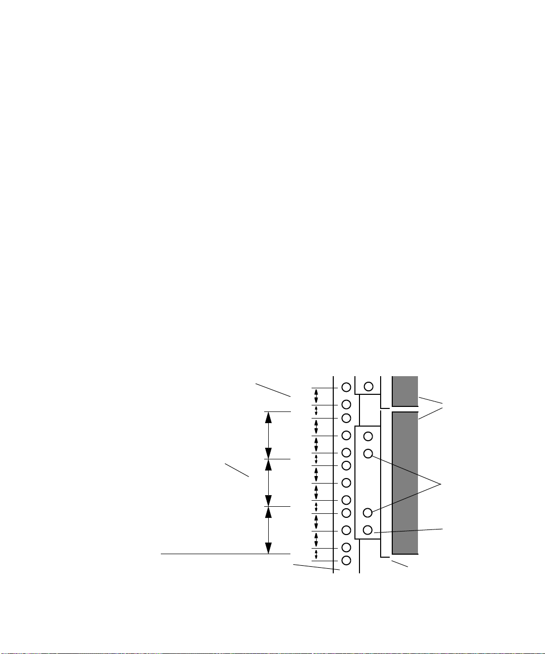
• You select the lowest full U-alignment position in the rack where you
can mount the drive enclosure. The drive enclosure uses 3 U of rack
space, or 5.25 inches of rack space. Position the drive enclosure
support rails so that the bottom of each rail is at the baseline of a
U-alignment position (see Figure 1).
• The rails do not interfere with the power strips, power cords, or other
cables at the back of the rack.
• The rails allow the drive enclosure to slide completely into the rack.
• The bottom of the drive enclosure is at the bottom of a U-alignment
position.
Rack channel hole spacing
5/8 in
1/2 in
3 U
2 U
1 U
5/8 in
5/8 in
1/2 in
5/8 in
5/8 in
1/2 in
5/8 in
5/8 in
1/2 in
Support rail
EIA rack unit
Baseline of drive
enclosure is at
U-alignment position
between two 1/2-inch
spaced holes.
Rack front channel
1 3/4 in
1 3/4 in
1 3/4 in
Figure 1 Locating the MEDIArray II Drive Enclosure Rails
Drive
enclosure
Support rail
mounting holes
MEDIArray II
mounting hole
27
Page 28
Chapter 2 Installing the MediaNetwork Storage Subsystem Hardware
n
Mounting the MEDIArray II Drive Enclosure
n
If you are installing the rails in a rack that does not have threaded
mounting holes, you will need to locate four clip nuts in the rail kit. Slip the
clip nuts over the holes in the rack front and back channels where you will
be installing the screws for the drive enclosure rails.
To place a rack-mount drive enclosure into the rack:
1. Make sure you have installed the rack-mount drive enclosure support
rails (see “Installing the MEDIArray II Drive Enclosure Rack-Mount
Rails” on page 27). If you are installing several drive enclosures,
install all the support rails before you begin to install the drive
enclosures.
When installing multiple MEDIArray II drive enclosures, make sure you
position each subsequent set of support rails approximately 3 U above the
bottom of the previous set of support rails. The holes in the rails should
align so that you can use the top or bottom holes.
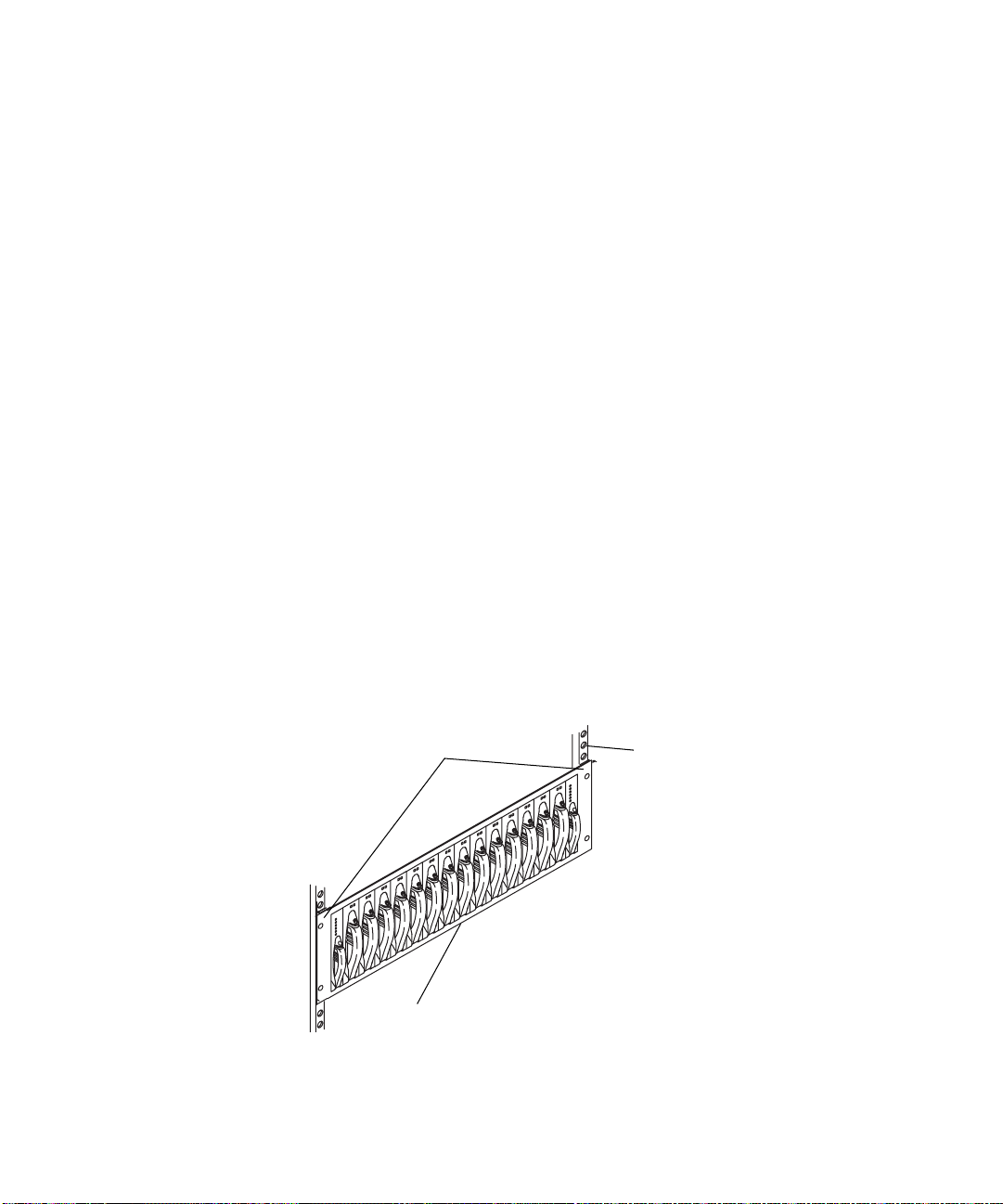
2. From the front of the rack, slide a drive enclosure onto the bottom set
of support rails. Push the drive enclosure in until the mounting
brackets on the side of the drive enclosure touch the front rack rail
(see Figure 2).
28
Mounting brackets
Drive enclosure
Figure 2 Installing a Drive Enclosure
Front rack rail
Page 29

3. Locate the mounting screws in the rail kit.
4. Attach the drive enclosure to the front rack rail using one mounting
screw on each side of the drive enclosure. The mounting screw can go
into either the top or the bottom hole in the mounting bracket.
5. If you are installing several rack-mount drive enclosures, repeat steps 2
to 4 for each additional drive enclosure.
Installing the MEDIArray II Drives
The MEDIArray II ships with the power supplies and ACMs installed.
However, you must install the MEDIArray II drives before you connect the
cables between the Fibre Channel controller, the MEDIArray II drive
enclosure, or the power cords. The drive slots are filled with dummy
drives. You need to remove some or all of the dummy drives and replace
them with MEDIArray II drives. The MEDIArray II drives are shipped
separately from the drive enclosure and must be installed in the drive
enclosure.
Installing File Managers and Storage Subsystem Components
c
n
n
c
Make sure you are wearing a grounding wrist strap that is attached to
the rack assembly before you remove or add any drives in the drive
enclosure.
Avid recommends that you do not mix different capacity MEDIArray II
drives in the same drive enclosure. Mount different-sized drives in separate
drive enclosures.
To install the drives:
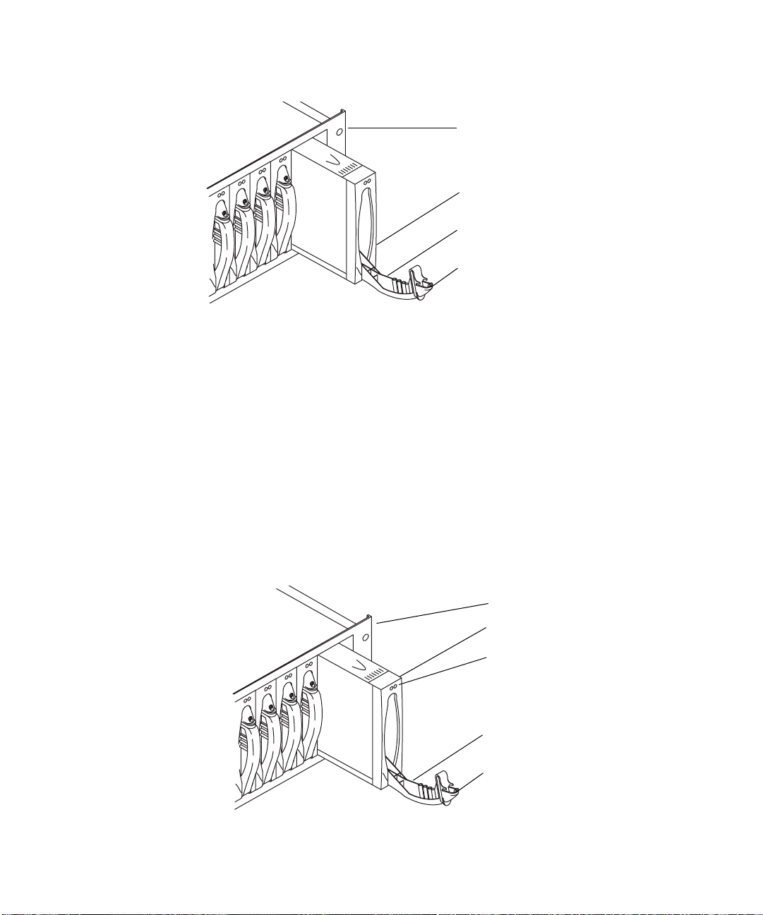
1. Starting with the first unpopulated slot, remove as many dummy drives
as you have drives in the MEDIArray II drive kit. Using your finger,
release the locking tab by pressing down, and pull the cam lever
toward you until the cam lever is fully open (see Figure 3).
Save the dummy drives. You might need to reinstall some of them later if
you rearrange the drives in your drive enclosures.
If you are not filling the drive enclosure with 14 drives, leave the
dummy drives in any unused slots to provide proper airflow within the
drive enclosure.
29
Page 30
Chapter 2 Installing the MediaNetwork Storage Subsystem Hardware
Drive enclosure
Dummy drive
Cam lever
Locking tab
Figure 3 Removing a Dummy Drive from the Drive Enclosure
2. Gently pull the dummy drive out of the enclosure.
3. Locate a drive in the MEDIArray II drive kit.
4. Remove the drive from the antistatic bag.
c
Use caution when you are handling the drives. They contain
components that can be damaged if you hit or drop the drive.
5. Grasp the drive assembly, and fully open the cam lever.
6. Align the drive assembly with the guides in the drive enclosure,
making sure the LEDs are on the top (see Figure 4).
Drive enclosure
Drive assembly
LEDs
Cam lever
Locking tab
Figure 4 Inserting a Drive into the Drive Enclosure
30
Page 31

Installing File Managers and Storage Subsystem Components
7. With the cam lever fully open, gently slide the drive into the drive
enclosure. To lock the drive assembly in place, lift up the cam lever.
You should hear the locking tab click when it engages.
c
Connecting the MEDIArray II Drive Enclosure Power Cords
Use caution when inserting the drives into the drive enclosure. You
could damage the protective strip mounted on one side of the drive if
you do not insert the drive properly.
8. Repeat steps 1 to 7 for each drive you are installing into the drive
enclosure.
Each MEDIArray II drive enclosure has two power cords, one for each
UPS. The power cord connectors are located on the rear panel below the
advanced cooling modules (ACMs).
To connect the power cords to the power supplies in a drive
enclosure:
1. Locate two power cords in the MEDIArray II kit.
2. Attach one power cord to the power connector in the right power
supply.
3. Attach the other power cord to the power connector in the left power
supply.
4. Check that the drive enclosure power switches are turned on.
n
By default, each drive enclosure ships with the power switch in the on
position.
5. Plug the power cords from the right side of each drive enclosure into a
power strip on the right side of the rack.
6. Plug the power cords from the left side of each drive enclosure into a
power strip on the left side of the rack.
7. Repeat steps 1 to 6 for each drive enclosure.
31
Page 32

Chapter 2 Installing the MediaNetwork Storage Subsystem Hardware
0
0
Setting the MEDIArray II Drive Enclosure IDs
Each MEDIArray II drive enclosure needs a unique enclosure ID number
to identify the drive enclosure and determine its drive addresses. The
enclosure IDs must be between zero and seven (0 and 7), and the IDs must
be in sequential order.
To set the drive enclosure IDs:
1. Locate the enclosure ID switch on the drive enclosure rear panel.
2. Use the + (plus sign) button to increment the drive enclosure ID or
the – (minus sign) button to decrement the drive enclosure ID
(see Figure 5).
3. Starting with the drive enclosure that is physically lowest in the rack,
set the ID to 0.
You might need to use
a pen or a paper clip to
push the + and - buttons
to change the drive
enclosure ID.
Decrement (–) button
Increment (+) button
Figure 5 Setting the Drive Enclosure ID
Enclosure ID switch
4. Move up to the next drive enclosure, and set the ID to 1.
5. Continue setting the drive enclosure IDs by moving up to the next
drive enclosure and incrementing the ID number by one from the
previous enclosure’s ID number.
6. Repeat step 5 until all the drive enclosure IDs are set. The last ID
number should be no higher than 7.
32
Page 33

Installing File Managers and Storage Subsystem Components
Installing a Standard Keyboard, Monitor, and Mouse
The File Manager ships with a keyboard and mouse. You need to supply a
monitor and a monitor shelf before you can connect the monitor to the File
Manager. You can provide your own monitor and shelf or purchase them
from Avid.
If you purchased a KMM assembly from Avid, continue with “Installing
the Keyboard, Monitor, and Mouse (KMM) Assembly” on page 34.
Installing the Shelf
Follow the installation instructions supplied with the shelf, ensuring that:
• The shelf does not interfere with the power strips, power cords, or
other cables at the back of the rack.
• The shelf allows the monitor to slide completely into the rack.
• You install the rails at the nearest U-alignment position.
• The bottom of the shelf is at the bottom of a U-alignment position.
Installing the Monitor
To install the monitor:
1. Set the monitor on the shelf.
2. Route the power cord and cable to the back of the shelf.
Connecting the Monitor Power Cord
To connect the monitor power cord:
1. Plug one end of the power cord into the back of the monitor.
2. Plug the other end of the power cord into the right power strip in the
back of the rack.
33
Page 34

Chapter 2 Installing the MediaNetwork Storage Subsystem Hardware
Installing the Keyboard, Monitor, and Mouse (KMM) Assembly
The KMM is a rack-mount assembly that includes a standard keyboard,
liquid crystal monitor, and trackball. It requires 1 U of rack space. The
monitor pivots and folds flat so that the KMM can slide into the rack for
storage when it is not in use.
The KMM is an option for the MediaNetwork workgroup. If your
workgroup does not include the KMM, you will need to use a standard PC
keyboard, PS/2 mouse, and monitor. To install these components, see
“Installing a Standard Keyboard, Monitor, and Mouse” on page 33.
Installing the KMM Rack-Mount Rails
Follow the instructions supplied with the KMM to install the rack-mount
rails, ensuring that:
• The rails do not interfere with the power strips, power cords, or other
cables at the back of the rack.
• The rails allow the KMM to slide completely into the rack.
Mounting the KMM
34
• The rails are installed at the nearest U-alignment position, which is
approximately 40 inches (1.016 meters) from the floor.
• The bottom of the KMM is at the bottom of a U-alignment position.
To mount the KMM on the rack-mount rails:
1. Align the fixed rails attached to the sides of the KMM with the sliding
rails attached to the rack.
2. Push the KMM onto the sliding rails and into the rack. You will hear
the rails click as they lock in place.
3. To make sure the KMM is properly seated, carefully pull it out of the
rack. Make sure that the KMM stops and does not come out of the
rack. Support the KMM in case the rails did not lock in place and the
KMM slides off the rails.
4. If the KMM does not stop, make sure its rails are aligned with the
sliding rails in the rack.
Page 35

Connecting the KMM Power Cord
To connect the KMM power cord:
1. Plug one end of the power cord into the back of the KMM assembly.
2. Plug the other end of the power cord into the left power strip in the
back of the rack.
Installing the MEDIASwitch
The MEDIASwitch connects the storage and clients to the File Manager. It
allows several clients to use the storage simultaneously and prevents
interruptions by allowing other clients in the workgroup to continue
working if one or more clients go offline. The switch is available in either
an 8-port or a 16-port version.
The MEDIASwitch mounts in the rack above the drive enclosures. If you
have two MEDIASwitches, then mount them with no space in between.
Installing File Managers and Storage Subsystem Components
Installing the MEDIASwitch Rack-Mount Rails
Follow the instructions supplied with the MEDIASwitch to install the rackmount rails, ensuring that:
• The rails do not interfere with the power strips, power cords, or other
cables at the back of the rack.
• The rails allow the MEDIASwitch to slide completely into the rack.
• The bottom of the MEDIASwitch is at the bottom of a U-alignment
position.
Mounting the MEDIASwitch
To mount the MEDIASwitch on the rack-mount rails:
1. Align the fixed rails attached to the sides of the MEDIASwitch with
the sliding rails attached to the rack.
2. Push the MEDIASwitch onto the sliding rails and into the rack. You
will hear the rails click as they lock in place.
35
Page 36

Chapter 2 Installing the MediaNetwork Storage Subsystem Hardware
3. To make sure the MEDIASwitch is properly seated, carefully pull the
MEDIASwitch out of the rack. Make sure that the switch stops and
does not come out of the rack. Support the MEDIASwitch in case the
rails did not lock in place and the switch slides off the rails.
4. If the switch does not stop, make sure its fixed rails are aligned with
the sliding rails in the rack.
MEDIASwitch Port Requirements
The MediaNetwork workgroup has specific requirements for placing
small form-factor pluggable (SFP) connectors into the MEDIASwitch
ports.
In the MediaNetwork workgroup, the MEDIASwitch can be configured for
up to two File Manager ports (ports 1 and 2), up to four storage ports on an
8-port switch (ports 5 to 8), or up to eight storage ports on a 16-port switch
(ports 9 to 16), with the remaining host ports available for MediaNetwork
Fibre attached clients. Figure 6 shows the configuration options for the
9100 and 9200 MEDIASwitch ports.
9100
MEDIASwitch
9200
MEDIASwitch
36
You can connect one File Manager to each File Manager port. You can
connect up to four drive enclosures to each storage port. You can connect
one MediaNetwork client to each host port.
MediaNetwork client ports
1
2
3
File Manager ports
4
5
Storage ports
6
8
7
MediaNetwork client ports
1
2
3
6
4
5
8
7
11
9
10
Storage ports
Figure 6 9x00 MEDIASwitch Port Layout
15
13
12
14
16
100Act/Col
l0l0l
MGMT
ENET
100Act/Col
l0l0l
MGMT
ENET
Page 37

Installing an SFP Connector
The MEDIASwitch can use up to eight or sixteen SFP connectors,
depending on the switch that is part of your MediaNetwork workgroup.
The SFP connectors allow you to attach cables from the File Manager, the
MediaNetwork clients, and the drive enclosures to the MEDIASwitch. SFP
connectors are supplied separately.
To install an SFP connector into a MEDIASwitch:
1. Locate an SFP connector in the MEDIASwitch kit.
2. Position an SFP connector in front of a MEDIASwitch port (see
Figure 7). Make sure the optical connector is facing away from the
MEDIASwitch and the pull handle is on the bottom.
MEDIASwitch 9200
Installing File Managers and Storage Subsystem Components
0
10
l
o
t/C
c
A
T
E
N
E
T
M
G
M
16
15
14
13
12
1
1
0
1
9
8
7
6
5
4
3
2
1
SFP connector
n
Figure 7 Installing an SFP Connector
3. Slide the SFP connector into the MEDIASwitch port. You should hear
the retainer clips click when they engage the port.
4. Repeat steps 1 to 3 for each SFP connector in your workgroup.
Remove any SFP connectors that are not populated. This will eliminate the
™
risk of invalid error messages being logged by your SAN InSite
software.
37
Page 38

Chapter 2 Installing the MediaNetwork Storage Subsystem Hardware
Connecting the MEDIASwitch Power Cord
To connect the MEDIASwitch power cord:
1. Plug one end of the power cord into the back of the switch.
2. Plug the other end of the power cord into the right power strip in the
back of the rack.
3. If you have two switches, plug the second MEDIASwitch power cord
into the left power strip in the back of the rack.
Installing the KVM Switch
The KVM switch allows you to connect the File Manager and multiple
MediaNetwork clients (such as TransferManager or MediaManager) to a
single keyboard, monitor, and mouse. The keyboard, monitor, and mouse
can be standalone devices (see “Installing the Keyboard, Monitor, and
Mouse (KMM) Assembly” on page 34) or a KMM assembly.
Installing the KVM Switch Rack-Mount Bracket
Follow the instructions supplied with the KVM switch to install the rackmount bracket, ensuring that:
• The bracket does not interfere with the power strips, power cords, or
other cables at the back of the rack.
• The bracket allows the KVM to slide completely into the rack.
• The bottom of the KVM is at the bottom of a U-alignment position.
Mounting the KVM Switch
To mount the KVM on the rack-mount bracket:
1. Align the KVM with the opening in the bracket.
2. Push the KVM into the bracket until the front of the KVM touches the
front of the rack. The indentations in the bottom of the KVM should
align with the support rails on the bracket.
3. Screw the bracket and the KVM together using the screws supplied
with the KVM.
38
Page 39

Connecting the KVM Power Cord
To connect the KVM power cord:
1. Plug one end of the power cord into the back of the KVM.
2. Plug the other end of the power cord into the right power strip in the
back of the rack.
Installing the File Manager
The File Manager controls the files on the storage subsystem and also
controls MediaNetwork client access to the files. The File Manager is rack
mountable and requires 2 U of rack space.
Your MediaNetwork workgroup might include a Failover File Manager to
limit downtime if there is a problem with the Primary File Manager.
Before you install the File Manager, you need to add the MediaNetwork
application key (also called a dongle). The application key determines how
many MediaNetwork clients can simultaneously use your MediaNetwork
workgroup.
Installing File Managers and Storage Subsystem Components
c
n
Do not lose the application key. Your MediaNetwork workgroup does
not function without it. If you lose the application key, you must
purchase another one from Avid to use your MediaNetwork software.
To connect the application key to your MediaNetwork workgroup:
1. Locate the application key in your MediaNetwork kit.
2. Attach the application key to the parallel printer port on the
MediaNetwork Server. Secure the application key with the
thumbscrews that are part of the key.
The File Manager ships with a parallel port and a Fibre Channel adapter
board (two Fibre Channel adapter boards when the File Manager is
configured for two switches). When the File Manager is configured for
automatic failover, a 10/100BASE-T Ethernet adapter board is also
installed.
39
Page 40

Chapter 2 Installing the MediaNetwork Storage Subsystem Hardware
c
Installing the File Manager Rack-Mount Rails
Mounting the File Manager
Do not use the built-in USB connectors on the front or the back of the
SR2200 File Manager; boot failures could result.
Follow the instructions supplied with the File Manager to install the rear
rack-mount rails, ensuring that:
• The brackets do not interfere with the power strips, power cords, or
other cables at the back of the rack.
• The brackets allow the File Manager to slide completely into the rack.
• The bottom of the File Manager is at the bottom of a U-alignment
position.
To mount the File Manager on the rack-mount brackets:
1. Attach the left and right front brackets to the File Manager.
2. Attach the rear support washers to the last mounting location on each
side of the File Manager.
3. Slide the File Manager into the rack, setting the support washers onto
the rack-mount brackets.
c
Connecting the File Manager Power Cord
40
If other equipment is installed close to the brackets, you might need
help in supporting the rear of the File Manager.
4. Attach the front mounting brackets to the rack rails.
To connect the File Manager power cord:
1. Plug one end of the power cord into the top power outlet on the back of
the File Manager.
2. Plug the other end of the power cord into the left power strip in the
back of the rack.
Page 41

Installing File Managers and Storage Subsystem Components
Installing the Failover File Manager
The Primary File Manager and Failover File Manager are identical
hardware components. If your MediaNetwork workgroup has a Failover
File Manager, follow the instructions in “Installing the File Manager” on
page 39.
Installing the Ethernet Hub
You use an Ethernet hub to connect the Primary File Manager, the Failover
File Manager, and the MEDIASwitches together. This allows you to
manage the switches from either File Manager.
Installing the Rack-Mount Bracket
Follow the instructions supplied with the Ethernet hub to install the rackmount bracket, ensuring that:
• The bracket does not interfere with the power strips, power cords, or
other cables at the back of the rack.
• The bracket allows the hub to slide completely into the rack.
• The bottom of the hub is at the bottom of a U-alignment position.
Mounting the Ethernet Hub
To mount the Ethernet hub on the rack-mount bracket:
1. Align the Ethernet hub with the opening in the bracket.
2. Push the Ethernet hub into the bracket until the front of the Ethernet
hub touches the front of the rack. The indentations in the bottom of the
Ethernet hub should align with the support rails on the bracket.
3. Screw the bracket and the Ethernet hub together using the screws
supplied with the Ethernet hub.
41
Page 42

Chapter 2 Installing the MediaNetwork Storage Subsystem Hardware
Connecting the Ethernet Hub Power Cord
To connect the Ethernet hub power cord:
1. Plug one end of the power cord into the back of the hub.
2. Plug the other end of the power cord into the right power strip in the
back of the rack.
Connecting the File Manager and Storage
The following sections describe how to connect the components in your
MediaNetwork workgroup.
If you are using a standard keyboard, monitor, and mouse, see “Connecting
a Standard Keyboard, Monitor, and Mouse to the File Manager” on
page 42.
If you are using a standard keyboard, monitor, and mouse, and a KVM, see
“Connecting a Standard Keyboard, Monitor, and Mouse to the KVM” on
page 43.
If you are using a KMM and a KVM, see “Connecting the KMM to the
KVM (Option)” on page 43.
Connecting a Standard Keyboard, Monitor, and Mouse to the File Manager
To connect a standard keyboard, monitor, and mouse to the File
Manager:
1. Locate the keyboard and mouse in the File Manager kit.
2. Locate the keyboard/mouse Y-cable in the File Manager kit.
3. Attach the right branch of the connector on the Y-cable to the
keyboard.
42
Page 43

Connecting the File Manager and Storage
4. Attach the left branch of the connector on the Y-cable to the mouse.
n
When connecting the Y-cable, you determine left and right by looking at
the back of the File Manager. Connect all left branch sections of Y-cables
to the mouse and right branch sections of Y-cables to the keyboard. The
KVM cable ends might not be marked with symbols for mouse and
keyboard.
5. Attach the 15-pin monitor connector to the monitor port on the back of
the File Manager.
Continue with “Connecting the File Manager to the MEDIASwitch” on
page 45.
Connecting a Standard Keyboard, Monitor, and Mouse to the KVM
To connect a standard keyboard, monitor, and mouse to the KVM:
1. Locate the keyboard and mouse in the File Manager kit.
2. Attach the connector on the keyboard cable to the keyboard port on the
back of the KVM.
3. Attach the connector on the mouse cable to the mouse port on the back
of the KVM.
4. Attach the 15-pin connector on the monitor cable to the monitor port
on the back of the KVM.
Continue with “Connecting the File Manager to the KVM (Option)” on
page 44.
Connecting the KMM to the KVM (Option)
To connect the KMM to the KVM:
1. Locate the 15-pin video connector on the KMM.
2. Attach the connector to the monitor connector on the back of the
KVM. Secure the connector with the thumbscrews in the connector.
43
Page 44

Chapter 2 Installing the MediaNetwork Storage Subsystem Hardware
3. Locate the cable with the keyboard and mouse connectors.
4. Push the keyboard cable connector into the keyboard connector on the
back of the KVM.
5. Push the mouse cable connector into the mouse connector on the back
of the KVM.
Connecting the File Manager to the KVM (Option)
To connect the File Manager to the KVM:
1. Locate the KVM cable in the File Manager kit. It has a 25-pin
connector on one end, and a 15-pin keyboard connector and a mouse
connector on the other end.
2. Attach the 25-pin connector to port 1 on the back of the KVM. Secure
the connector with the thumbscrews in the connector.
3. Attach the 15-pin connector to the video port on the back of the File
Manager. Secure the connector with the thumbscrews in the connector.
44
n
4. Locate the keyboard/mouse Y-cable in the File Manager kit.
5. Attach the single cable end of the Y-cable to the keyboard/mouse port
on the back of the File Manager.
6. Attach the right branch of the Y-cable to the keyboard cable coming
from the KVM.
7. Attach the left branch of the Y-cable to the mouse cable coming from
the KVM.
When connecting the Y-cable, you determine left and right by looking at
the back of the File Manager. Connect all left branch sections of Y-cables
to the mouse and right branch sections of Y-cables to the keyboard. The
KVM cable ends might not be marked with symbols for mouse and
keyboard.
Page 45

Connecting the File Manager and Storage
Connecting the Failover File Manager to the KVM
To connect the Failover File Manager to the KVM:
1. Locate the KVM cable in the File Manager kit. It has a 25-pin
connector on one end, and a 15-pin keyboard connector and a mouse
connector on the other end.
2. Attach the 25-pin connector to port 2 on the back of the KVM. Secure
the connector with the thumbscrews in the connector.
3. Attach the 15-pin connector to the video port on the back of the
Failover File Manager. Secure the connector with the thumbscrews in
the connector.
4. Locate the keyboard/mouse Y-cable in the File Manager kit.
5. Attach the single cable end of the Y-cable to the keyboard/mouse port
on the back of the File Manager.
6. Attach the right branch of the Y-cable to the keyboard cable coming
from the KVM.
7. Attach the left branch of the Y-cable to the mouse cable coming from
the KVM.
n
When connecting the Y-cable, you determine left and right by looking at
the back of the File Manager. Connect all left branch sections of Y-cables
to the mouse and right branch sections of Y-cables to the keyboard.
Connecting the File Manager to the MEDIASwitch
To connect the File Manager to the MEDIASwitch:
1. Locate a 10-foot (3-meter) optical cable in the File Manager kit.
n
If the File Manager is set up for dual switches, two Fibre Channel adapter
boards are installed. Attach the first cable to the top board in the File
Manager PCI card bracket on the back of the File Manager.
2. Attach one end of the cable to the Fibre Channel adapter board
populating the top slot in the File Manager PCI card bracket. Secure
the optical cable by firmly inserting the connector into the optical port.
45
Page 46

Chapter 2 Installing the MediaNetwork Storage Subsystem Hardware
3. Attach the other end of the cable to port 1 on the first switch.
4. If you have a second switch, locate another 10-foot (3-meter) optical
cable in the File Manager kit.
5. Attach one end of the cable to the Fibre Channel adapter board
populating the middle slot in the File Manager PCI card bracket. For
more information on the File Manager PCI card brackets, see Avid
SR2200 Platform Introduction.
6. Attach the other end of the cable to port 1 on the second switch.
Connecting the Failover File Manager to the MEDIASwitch
To connect the Failover File Manager to the MEDIASwitch:
1. Locate a 10-foot (3-meter) optical cable in the File Manager kit.
n
If the File Manager has two Fibre Channel adapter boards, attach the
cable to the top board in the File Manager PCI card bracket.
2. Attach one end of the cable to the Fibre Channel adapter board. Secure
the optical cable by firmly inserting the connector into the optical port.
3. Attach the other end of the cable to port 2 on the first switch.
4. If you have a second switch, locate another 10-foot (3-meter) optical
cable in the File Manager kit.
5. Attach one end of the cable to the Fibre Channel adapter board
populating the middle slot in the Failover File Manager PCI card
bracket.
6. Attach the other end of the cable to port 2 on the second switch.
Connecting the MEDIASwitch Serial Port to the File Manager for Initial Switch Configuration
Connect the MEDIASwitch serial port to the File Manager to
accommodate changing the switch IP address in your initial switch
configuration.
46
Page 47

Connecting the File Manager and Storage
0
To connect the MEDIASwitch to the File Manager:
1. Locate the RJ45-to-9-pin serial adapter in the File Manager kit.
2. Locate the serial cable supplied with the MediaSwitch.
3. Connect the RJ45-to-9-pin serial adapter to the RJ45 Serial port on the
rear panel of the File Manager.
4. Connect a serial cable from the MediaSwitch to the 9-pin connector on
the serial adapter.
5. Connect a serial cable from the MediaSwitch to the 9-pin connector on
the MediaSwitch.
n
If you have two switches, you can move the serial cable from one switch to
the other when you need to change the other switch’s IP address. See
“Adding the MEDIASwitch Address to the hosts File” on page 62.
Connecting the MEDIArray II Drive Enclosure to the MEDIASwitch
Each MEDIArray II drive enclosure contains two I/O modules. The I/O
modules connect the storage to the MEDIASwitches. Figure 8 shows the
locations of the I/O modules on the rear of the drive enclosure.
I/O module I/O module
INPUTOUTPUT
Figure 8 Drive Enclosure Connection Locations
AB
INPUTOUTPUT
47
Page 48

Chapter 2 Installing the MediaNetwork Storage Subsystem Hardware
Each I/O module has two connectors: the primary (INPUT) connector and
the expansion (OUTPUT) connector (see Figure 8). The INPUT port on
the I/O module accepts data from a host or another I/O module when two
drive enclosures are daisy-chained. The OUTPUT port on the I/O module
passes data to the INPUT port on the next I/O module when two drive
enclosures are daisy-chained.
You connect the drive enclosures to the MEDIASwitch either individually
or in pairs. The number of drive enclosures and MediaNetwork clients that
you have in your workgroup, and the type of work that the clients do,
determine how you need to connect the drive enclosures to the switch. You
typically connect several groups of drive enclosures, up to the maximum of
eight enclosures, to the switch.
For cabling instructions on connecting one drive enclosure, see
“Connecting One MEDIArray II Drive Enclosure” on page 48.
For cabling instructions on connecting a daisy-chain of two drive
enclosures, see “Connecting a Daisy Chain of Two MEDIArray II Drive
Enclosures” on page 50.
Connecting One MEDIArray II Drive Enclosure
When you have one drive enclosure in your MediaNetwork workgroup or
Trilligent Cluster, you connect it directly to the MEDIASwitch
(see Figure 9).
MEDIASwitch
Drive
enclosure
MEDIArray II
Figure 9 Cabling for One MEDIArray II Drive Enclosure
48
Input
Cable
Page 49

Connecting the File Manager and Storage
Connecting the Cable to the MEDIArray II Drive Enclosure
To connect the MEDIArray II drive enclosure:
1. Locate a 10-foot (3-meter) optical cable in the MEDIArray II kit. The
cable has an LC (small) optical connector on both ends.
2. Attach the connector on one end of the cable to the INPUT connector
on I/O module A on the back of drive enclosure 1 (see Figure 8).
Secure the optical cable by firmly inserting the connector into the
optical port.
Connecting an LC Optical Cable to a 2-Gb MEDIASwitch
To connect an LC optical cable to a 2-Gb MEDIASwitch:
1. Locate an SFP connector in the MEDIArray II drive enclosure kit.
2. Route the LC optical cable from the MEDIArray II drive enclosure to
the MEDIASwitch, if it has not already been installed.
3. Position the SFP connector in front of a MEDIASwitch port. Make
sure the optical connector is facing away from the MEDIASwitch and
the pull-tab is down (see Figure 10 for SFP placement and Figure 11 to
determine the type of port to which you are connecting).
n
0
10
l
o
C
/
t
c
A
ENET
T
GM
MEDIASwitch 9100
3
2
1
8
7
6
5
4
SFP connector
M
Figure 10 Installing an SFP Connector
You can install the SFP connector while the MEDIASwitch is turned on.
49
Page 50

Chapter 2 Installing the MediaNetwork Storage Subsystem Hardware
4. Slide the SFP connector into the MEDIASwitch port. You should hear
the retainer clips click when they engage the port.
5. Remove the protective covers from the optical connector on the optical
cable.
6. Remove the protective cover from the SFP connector in the
MEDIASwitch.
7. Attach the connector on the cable to the SFP connector for the storage
port (see Figure 11 to determine the type of port to which you are
connecting). Firmly push the cable plug into the connectors on the
optical SFP connector.
8. Label the cable with the name or location of the MEDIArray II drive
enclosure to which it connects.
MediaNetwork client ports
9100
3
6
4
5
8
7
1
2
MEDIASwitch
File Manager ports
Storage ports
MediaNetwork client ports
9200
1
2
3
6
4
5
8
7
11
9
12
10
15
13
14
MEDIASwitch
Storage ports
Figure 11 MEDIASwitch 9x00 Port Layout
Connecting a Daisy Chain of Two MEDIArray II Drive Enclosures
When you have multiple drive enclosures in your MediaNetwork
workgroup or Trilligent Cluster, you can create daisy chains of two drive
enclosures to connect to the MEDIASwitch (see Figure 12).
100Act/Col
l0l0l
MGMT
ENET
16
100Act/Col
l0l0l
MGMT
ENET
50
Page 51

Connecting the File Manager and Storage
MEDIASwitch
Drive
enclosures
MEDIArray II
Cables
#2
MEDIArray II
#1
Daisy-chain cable
Figure 12 Cabling for Two MEDIArray II Drive Enclosures
To connect the drive enclosures:
1. Locate a 10-foot (3-meter) optical cable in the MEDIArray II kit.
2. Attach the optical connector on one end of the cable to any of the
unpopulated switch ports 5 to 8 on an 8-port switch or ports 9 to 16 on
a 16-port switch (see Figure 13). Secure the optical cable by firmly
inserting the connector into the SFP connector.
3. Attach the optical connector on the other end of the optical cable to the
INPUT optical connector on I/O module A on the back of drive
enclosure 1 (see Figure 14). Secure the optical cable by firmly
inserting the connector into the optical port.
Switch ports 5 to 8
1
2
3
6
4
5
8
7
100Act/Col
l0l0l
MGMT
ENET
To drive enclosures
Figure 13 MEDIASwitch 9100 Port Configuration
4. Locate a 1-foot (0.3-meter) optical cable in the kit.
5. Attach the optical connector on one end of the cable to the OUTPUT
optical connector on I/O module A on the back of drive enclosure 1
(see Figure 14). Secure the optical cable by firmly inserting the
connector into the optical port.
51
Page 52

Chapter 2 Installing the MediaNetwork Storage Subsystem Hardware
0
0
6. Attach the optical connector on the other end of the cable to the
INPUT optical connector on I/O module A on the back of drive
enclosure 2 (see Figure 14). Secure the optical cable by firmly
inserting the connector into the optical port.
Drive enclosure 2
Optical Cable
to switch
INPUTOUTPUTINPUTOUTPUT
Drive enclosure 1
Figure 14 Daisy Chaining Drive Enclosures
Connecting to Two MEDIASwitches
When you have two MEDIASwitches in your MediaNetwork workgroup,
you need to connect cables from I/O module A on the drive enclosures to
the first switch and from I/O module B on the drive enclosures to the
second switch (see Figure 15).
n
Connect cables from I/O module A and I/O module B to the same ports on
both switches.
INPUT
Daisy chain
cable OUT
Daisy chain
cable IN
On an 8-port switch, you can use ports 5 to 8 to connect drive enclosures.
On a 16-port switch, you can use ports 9 to 16 to connect drive enclosures.
52
Page 53

Connecting the File Manager and Storage
MEDIASwitch 1
Ports 7 and 8 (or 15 and 16)
I/O Module A cables
Daisy-chain cable
Drive
enclosures
MEDIASwitch 2
Ports 7 and 8 (or 15 and 16)
I/O Module B cables
Figure 15 Cabling for Two MEDIASwitches
Connecting the Ethernet Switch in a MediaNetwork System
You must connect an Ethernet switch to your Ethernet local area network
(LAN) to enable the clients in a PortServer Pro workgroup to do the
following:
• Obtain a license to use the PortServer Pro (The File Manager must also
be connected to the LAN.)
• Easily share project information with other MediaNetwork or
PortServer Pro clients
• Use other Media Services (such as MediaManager)
A connection to a LAN is required to allow access by PortServer Pro
clients to MediaNetwork workspaces shared by the PortServer system. The
following sections provide information to install an Ethernet switch.
You can connect the Ethernet switch directly to your LAN or to an
®
additional Ethernet switch that you purchased from Avid (an Asanté
®
FriendlyNET
GX5-208 or an Asanté IntraCore™ 65120-2G). This
additional switch allows you to connect the File Manager, all the
PortServers, and the MEDIASwitches to simplify the network and
MEDIASwitch management. For more information on PortServer Pro
configurations, see the Avid Unity MediaNetwork PortServer Setup Guide.
53
Page 54

Chapter 2 Installing the MediaNetwork Storage Subsystem Hardware
Connecting the File Manager to the Ethernet Switch
To connect the File Manager to the Ethernet switch:
1. Locate an Ethernet cable in the File Manager kit.
2. Attach one end of the cable to port 1 on the switch.
3. Attach the other end of the cable to the File Manager Ethernet adapter
card in the PCI card bracket.
c
Connecting your File Manager to an Ethernet switch is optional in a
MediaNetwork workgroup but mandatory in a Trilligent Cluster.
Connecting the Failover File Manager to the Ethernet Switch
To connect the Failover File Manager to the Ethernet switch:
1. Locate an Ethernet cable in the File Manager kit.
2. Attach one end of the cable to port 2 on the switch.
3. Attach the other end of the cable to the File Manager built-in Ethernet
port 1.
Connecting the MEDIASwitch to the Ethernet Switch
To connect the MEDIASwitch to the Ethernet switch:
1. Locate an Ethernet cable in the MEDIASwitch kit.
2. Attach one end of the cable to port 3 on the switch.
3. Attach the other end of the cable to the MGMT ENET connector on
the back of the switch.
54
n
4. If you have a second switch, repeat steps 1 to 3 using port 4 on the
switch instead.
The MEDIASwitches have the same IP address by default. For more
information on IP address configuration, see Table 1 on page 56.
Page 55

Connecting the File Manager and Storage
Cross-Connecting the File Managers in a Failover Configuration
Use Figure 16, Tabl e 1, and the following instructions to connect and
configure the File Managers for failover operation.
Primary SR2200 File Manager
Parallel port
Crossover cable
between RJ45
Ethernet
connectors 2
Failover Ethernet
connector 1 to
LAN/WAN/s w itch
Primary Ethernet
connector 1 to
LAN/WAN/s witch
Crossover cable between
PCI 10/100 interface cards
Failover SR2200 File Manager
Figure 16 File Managers in a Failover Configuration
To connect the Primary File Manager and Failover File Manager:
1. Connect RJ45 Ethernet connector 2 of the Primary File Manager to
RJ45 Ethernet connector 2 of the Failover File Manager using the
crossover cable from the File Manager kit.
2. Connect the Primary File Manager RJ45 10/100BASE-T Ethernet port
on the full-height PCI network interface card (NIC) to the Failover File
Manager RJ45 10/100BASE-T Ethernet port on the full-height PCI
NIC.
3. Connect RJ45 Ethernet connector 1 of the Primary File Manager to
your LAN/WAN (MediaNetwork) or optional Ethernet switch
(PortServer Pro).
4. Connect RJ45 Ethernet connector 1 of the Failover File Manager to
your LAN/WAN or optional Ethernet switch.
5. Configure the IP addresses for the File Managers as shown in Tab le 1.
55
Page 56

Chapter 2 Installing the MediaNetwork Storage Subsystem Hardware
Table 1 File Manager IP Addresses
IP Address Description
192.168.1.1
192.168.2.1 Primary File Manager RJ45 Ethernet connector 2
192.168.3.1 Primary File Manager 10/100 Ethernet PCI NIC
192.168.1.2
192.168.2.2 Failover File Manager RJ45 Ethernet connector 2
192.168.3.2 Failover File Manager 10/100 Ethernet PCI NIC
a. The default IP address to use for configuring the Fibre Channel switch initially.
n
When you view the IP addresses in a Windows NT environment, the File
Manager Ethernet connector numbering is reversed:
a
a
Change this IP address to comply with your specific LAN IP addressing
conventions when configuring the Fibre Channel switch for use in your
network.
Primary File Manager RJ45 Ethernet connector 1
Failover File Manager RJ45 Ethernet connector 1
• Connector 1 is shown as connector 2.
• Connector 2 is shown as connector 1.
• Connector 3, the RJ45 10/100BASE-T Ethernet full-height PCI NIC
(when installed) maintains its numerical position.
56
For actual port and NIC locations, see Figure 16.
Page 57

Chapter 3
Configuring the MEDIASwitches
This chapter describes how to install the appropriate software and how to
configure the MEDIASwitches in your MediaNetwork workgroup or
Trilligent Cluster. Installing the necessary software is a multistep process.
Make sure you complete the sections in sequential order.
n
The IP addresses used in the following sections are recommendations.
They are nonrouting IP addresses and can be used if your site currently
does or does not have an Ethernet network. If your site has an Ethernet
network, you can select unused IP addresses from your network
environment for the MEDIASwitches.
Changing the MEDIASwitch IP Address
You initially connect to the MEDIASwitch from the File Manager using
the serial cable that you installed earlier (see “Connecting the
MEDIASwitch Serial Port to the File Manager for Initial Switch
Configuration” on page 46). Make sure the serial cable is connected to
both the File Manager and the MEDIASwitch you want to configure.
The MEDIASwitch ships with a default IP address of 192.168.1.129. If
you are not changing the IP address of the switch to an address on your
internal network, continue with “Establishing a Connection to the
MEDIASwitch” on page 62.
Page 58

Chapter 3 Configuring the MEDIASwitches
n
n
If you have two MEDIASwitches and your File Manager and switches are
connected to an Ethernet network, you should turn off one switch before
running SAN InSite Professional for the first time to configure the switch
IP addresses. This prevents SAN InSite Professional from seeing duplicate
IP addresses that can cause it to not recognize either switch.
If you have two MEDIASwitches, you need to change the IP address of the
second switch so that it does not conflict with the first switch. If you are not
changing the IP address to an address on your internal network, use the IP
address 192.168.1.130.
To change the IP address of the switch:
1. Open a terminal session through a terminal emulation program, such
as HyperTerminal
following serial port parameters:
- Bits per second: 19200
- Data bits: 8
- Parity: None
- Stop bits: 1
- Flow control: Xon/Xoff
®
, with the serial port set to COM 2 and the
58
2. Press Enter. A Password dialog box opens in the HyperTerminal
window.
3. Type the password manage in the text box to start the Command Line
Interface (CLI) .
4. At the Root menu prompt, type 1 (Config) and press Enter. The Config
window opens.
5. At the Config prompt, type 8 (Com) and press Enter. The Config/Com
window opens.
6. At the Config/Com prompt, type 4 (Ethernet) and press Enter. The
Ethernet window opens.
7. To change the MEDIASwitch Ethernet IP address, type 3 (Set Ethernet
Address) and press Enter.
8. At the IP Address prompt, type the new IP address and press Enter.
9. At the Ethernet window, type 4 (Netmask) and press Enter.
Page 59

Installing the SAN InSite Professional Software
10. At the Netmask prompt, type the Netmask and press Enter.
11. At the Ethernet window, type 5 (Gateway IP address) and press Enter.
12. At the Gateway IP Address prompt, type the new Gateway IP address
and press Enter.
13. Reset the MEDIASwitch by unplugging it and then plugging it in
again for the changes to take effect.
14. Log out of the CLI by typing logout at the prompt.
15. Close the HyperTerminal window.
Installing the SAN InSite Professional Software
MediaNetwork v3.2 uses an updated release of SAN InSite Professional
software to configure the MEDIASwitches.
To install SAN InSite Professional:
1. Locate the SAN InSite Professional CD-ROM.
2. Insert the CD-ROM into the File Manager CD-ROM drive. The
CD-ROM is set to automatically start the SAN InSite Professional
installation. This takes approximately 1 minute. The Verify Account
Privileges dialog box opens.
3. If the CD-ROM does not start automatically, then start the installation
manually as follows:
a. Double-click the My Computer icon on the desktop. The My
Computer window opens.
b. Right-click the CD-ROM icon, and select AutoPlay. The SAN
InSite Professional installation starts. The Verify Account
Privileges dialog box opens.
4. Click Yes. The SAN InSite Professional window opens to the
Introduction screen.
5. Click Next. The License Agreement screen appears.
6. Read the agreement and click Yes.
7. Click Next. The Choose One Item To Install screen appears.
59
Page 60

Chapter 3 Configuring the MEDIASwitches
8. Select SAN InSite Professional.
9. Click Next. The Choose A Directory screen appears. Make no
changes.
10. Click Next. The Enter Server Address screen appears, showing the
host name for the File Manager. If it is correct, click Yes. Write down
the host name; you will need it later.
11. Click Next. The Enter License screen appears.
12. Type the license number in the text box. The license number is on the
CD-ROM case.
13. Click Next. The License Status screen appears, showing the status of
the license. It should indicate the number of agents available and the
license expiration date.
14. Click Next. The Installation screen appears, showing the software
installation progress. When the software installation is complete, the
SAN InSite Professional Server Configuration window opens.
15. Click the Log tab.
60
16. Select each check box to turn on all the event-logging capabilities.
17. From the “Site log entry priority levels” menu, select
“info,config,warning,fail”.
18. Click the Discover tab.
19. Select the “Discover agents listed below” check box. The Add button
becomes available.
20. Click the Add button. The Add Agent IP Address/DNS Host Name
dialog box opens.
21. Type the IP address for your MEDIASwitch in the text box, and click
OK. The IP address appears in the list on the Discover tab.
22. If you have two MEDIASwitches, repeat step 21 for the second switch.
23. Click OK. A message box opens, stating that the configuration was
successful.
24. Click OK. The SAN InSite Professional Install Complete screen
appears.
25. Click OK. The SAN InSite Professional window closes.
Page 61

Configuring the MEDIASwitch
26. Click the Start button, and then select Shut Down. The Shut Down
Windows dialog box opens.
27. Select Restart and click OK. The File Manager reboots.
28. When the reboot is complete, log in as Administrator.
Configuring the MEDIASwitch
You need to configure the MEDIASwitch to have a valid IP address and to
have appropriate port configurations for the File Manager, MediaNetwork
clients, and drive enclosures in your MediaNetwork workgroup or
Trilligent Cluster.
Copying the MEDIASwitch Files into the SAN InSite Folder
The MEDIASwitch has configuration files that you need to copy into the
SAN InSite Pro folder.
To copy the MEDIASwitch configuration files:
1. Insert the MediaNetwork CD-ROM into the File Manager CD-ROM
drive.
2. Click the Start button, and select Programs > Windows NT Explorer.
The Windows NT Explorer window opens.
3. Navigate to the following location on the CD-ROM:
\Drivers_Firmware\FibreChannelSwitches\Vixel
4. Navigate to the following location on drive C:
\SANInSitePro\SIFileSystemRoot\deviceconfig\vixel
5. Drag the \Drivers_Firmware\FibreChannelSwitches\Vixel folder to the
\SANInSitePro\SIFileSystemRoot\deviceconfig\vixel folder.
6. Right-click the folder, and select Copy Here. The files are copied to
the new location.
61
Page 62

Chapter 3 Configuring the MEDIASwitches
Adding the MEDIASwitch Address to the hosts File
You need to add the MEDIASwitch IP address to the hosts file to
download switch firmware and make other updates.
To add the MEDIASwitch IP address to the hosts file:
1. Navigate to the following location:
%systemroot%\system32\drivers\etc
where %systemroot% is typically C:\Winnt.
2. Open the hosts file with a text editor, such as WordPad.
3. Scroll to the end of the file.
4. On a new line, type the correct IP address and switch name for your
switch in the following format:
192.168.1.129 #9x00 switch
5. If you have two switches, repeat step 4 for the second switch, using its
IP address.
6. Close and save the hosts file.
Establishing a Connection to the MEDIASwitch
To establish a connection to the switch:
1. Click the Start button, and select Programs >
SAN InSite Professional > Run SAN InSite Client. The SAN InSite
Professional Server Specification dialog box opens, showing the
server IP address or server DNS name.
2. Click Connect. The SAN InSite Professional User Authorization
dialog box opens.
3. Click Monitor & Manage. The Password dialog box opens.
4. Type manage in the Password dialog box.
5. Click OK. The SAN InSite Professional window opens. The switch IP
address is displayed in green.
62
Page 63

Setting the MEDIASwitch Configuration
This section describes how to configure the MEDIASwitch.
To download the MEDIASwitch firmware and configuration file:
1. Connect a crossover Ethernet cable between the File Manager Ethernet
port and the switch MGMT port.
2. Click the Start button, and select Programs >
SAN InSite Professional > Run SAN InSite Client. The SAN InSite
Professional Server Specification dialog box opens, showing the
server host name.
3. Click Connect. The SAN InSite Professional User Authorization
dialog box opens.
4. Click Monitor & Manage. The Password dialog box opens.
5. Type manage in the Password dialog box.
6. Click OK. The SAN InSite Professional Server window opens.
7. Double-click the switch you want to update. The Switch window
opens.
Configuring the MEDIASwitch
8. Select Tools > Configure firmware image. The Firmware Image
Configuration window opens.
9. Click Browse. The Select File dialog box opens.
10. Navigate to the following location:
Vixel\Firmware\YGb \Vixel_nnnn
where nnnn is the model number of your switch and Y is the switch
speed (1 Gb or 2 Gb).
11. Click the .dwn file in the switch folder.
12. Click OK. The firmware file name appears in the File Name text box
in the Firmware Image Configuration window.
13. Click Download. The firmware downloads to the Active Image in the
switch. When the download is complet, a dialog box opens, asking if
you want to set both images to the new firmware.
63
Page 64

Chapter 3 Configuring the MEDIASwitches
c
Avid recommends that you download the new firmware to both the
Active Image and the Alternate Image. This prevents problems if the
switch should change from the Active Image to the Alternate Image
for any reason.
14. Click Yes to select a configuration file to download with the firmware.
The Select File dialog box opens.
15. Navigate to the following location:
Vixel\Config Files\YGb \Vixel_nnnn
where nnnn is the model number of your switch and Y is the switch
speed (1 Gb or 2 Gb).
16. Select the configuration file in the switch folder. The files have the
following naming convention:
9100_tm_1fm_3h_4j
Number of MEDIArray enclosure connections
Number of clients
Number of File Managers
Target mode enabled
MEDIASwitch model
17. Click OK. The firmware and the switch configuration file download to
the Active Image and Alternate Image, and the switch resets. This
takes approximately 4 minutes.
18. When the download and reset are complete, close the Switch window.
n
After you have configured the MEDIASwitch, the name of the switch in the
SAN InSite Professional main window should match the name of the
configuration file you downloaded.
Starting the SAN InSite Server Manually
c
64
Avid has discovered performance issues when you run the SAN InSite
Server in most MediaNetwork configurations. You can avoid these
issues by stopping the SAN InSite Server and changing the SAN InSite
Service to start manually.
Page 65

To reset the SAN InSite service:
1. Click the Start button, and select Programs >
SAN InSite Professional > SAN InSite server > Stop Server.
2. Click the Start button, and select Settings > Control Panel. The Control
Panel opens.
3. Double-click the Services icon. The Services dialog box opens.
4. Select the SAN InSite Professional v3.5 service in the list of services.
5. Click Startup. The Service dialog box opens.
6. In the Startup Type area, click Manual.
7. Click OK. The Service dialog box closes, and the service is reset.
8. Click Close.
Using the SAN InSite Client
Using the SAN InSite Client
n
Avid recommends that you do not run the SAN InSite client and the File
Manager software at the same time. Use the Monitor Tool to stop the File
Manager before you run the SAN InSite client.
To change your MEDIASwitch settings using the SAN InSite client:
1. Use the Monitor Tool to stop the File Manager.
2. Click the Start button, and select Programs >
SAN InSite Professional > SAN InSite Server > Start Server. Because
it takes the server software about 20 seconds to start, wait before
continuing with step 3.
3. Click the Start button, and select Programs >
SAN InSite Professional > Run SAN InSite Client.
4. Log in to SAN InSite as usual, and make the necessary changes.
5. Quit the SAN InSite client.
6. Click the Start button, and select Programs >
SAN InSite Professional > SAN InSite Server > Stop Server.
7. Use the Monitor Tool to start the File Manager.
65
Page 66

Chapter 3 Configuring the MEDIASwitches
66
Page 67

Chapter 4
Configuring the File Manager
This chapter describes how to configure and install the appropriate
software on the File Managers in your MediaNetwork workgroup or
Trilligent Cluster. Installing the necessary software is a multistep process.
Make sure you complete the sections in sequential order.
Before you start the procedures in this chapter, you should have installed
the File Managers and other MediaNetwork workgroup or Trilligent
Cluster hardware.
n
The IP addresses used in the following sections are recommendations.
They are nonrouting IP addresses and can be used if your site currently
does or does not have an Ethernet network. If your site has an Ethernet
network, you can select unused IP addresses from your network
environment for the File Manager.
Setting Up the File Manager
Set up the File Manager and, in failover configurations, the second File
Manager as described in the following sections.
Page 68

Chapter 4 Configuring the File Manager
Quick File Manager Setup Summary
If you are already familiar with configuring the Windows NT systems, you
can skip the detailed instructions in the rest of this chapter and perform the
steps outlined here.
• Check that the File Manager is running the Windows NT 4.0 operating
system with Service Pack 5 and the ScsiPort.sys hotfix.
• Set the correct date, time, time zone, and daylight saving time option.
• Configure IP addresses and, if necessary, gateway IP addresses for the
network adapter.
• Configure the paging file size to be twice the installed RAM size on
drive D. See “Setting the Paging File Size” on page 70.
Checking the Operating System Installation
The File Manager runs the Windows NT 4.0 operating system with Service
Pack 5 and the ScsiPort.sys hotfix.
68
n
Avid ships the File Manager with Windows NT, Service Pack 5, and the
ScsiPort.sys hotfix preinstalled. To check that these software components
have been installed, follow the procedures in this section.
To determine that the appropriate Windows NT operating system,
service pack, and hotfix versions are installed on the File Manager:
1. Click the Start button, and select Programs > Administrative Tools >
Windows NT Diagnostics. The Windows NT Diagnostics window
opens.
2. Click the Version tab. The version of the Windows NT operating
system and service pack installed on the File Manager appears below
the Windows icon.
3. Click the Start button, and select Settings > Control Panel. The Control
Panel opens.
4. Double-click the Add/Remove Programs icon. The Add/Remove
Programs dialog box opens. The ScsiPort.sys hotfix is listed here if it
is installed.
Page 69

Setting Up the File Manager
If your File Manager does not have the Windows NT 4.0 operating system,
Service Pack 5, or the ScsiPort.sys hotfix installed, you should install the
components that are missing.
When you reinstall the Windows NT operating system for any reason,
perform a default installation (accept all the standard installation
recommendations) of the Windows NT 4.0 operating system. Follow the
Windows NT installation instructions that came with your Windows NT
software.
n
Windows NT Service Pack 5 and the ScsiPort.sys hotfix are provided in the
Extras folder on the MediaNetwork CD-ROM.
Setting the Date, Time, Time Zone, and Daylight Saving Time Option
You need to set the correct date, time, time zone, and daylight saving time
option on the File Manager. This allows the “Synchronize time with File
Manager” function on the MediaNetwork clients to work correctly.
To set the date, time, time zone, and daylight saving time option on
the File Manager:
1. Double-click the time in the taskbar. The Date/Time Properties dialog
box opens.
2. Set the date and time using the Date & Time tab.
3. Click the Time Zone tab.
4. Set the time zone for the location of the File Manager. By default,
Windows NT 4.0 sets the time zone to “(GMT - 8:00) Pacific Time
(US & Canada); Tijuana.”
5. Select “Automatically adjust clock for daylight saving changes.”
6. Click OK to close the Date/Time Properties dialog box and save the
settings.
69
Page 70

Chapter 4 Configuring the File Manager
Setting the Paging File Size
The paging file extends the physical memory (RAM) in your File Manager
by using a portion of the hard drive as a location to move unused data from
physical memory. Windows NT uses the paging file (pagefile.sys) to track
the size and location of the reserved hard drive space and to move data to
the hard drive from RAM.
n
n
Avid ships all File Managers with the paging file configured to 2048 MB.
The File Manager allocates 2048 MB of memory on drive D of the internal
(system) hard drive. This provides adequate space for normal File Manager
operation.
To set the paging file size for the File Manager:
1. Right-click the My Computer icon on the desktop, and select
Properties. The System Properties dialog box opens.
2. Click the Performance tab. The Performance settings appear.
3. Click Performance Options. The Performance Options dialog box
opens.
4. Click Change. The Virtual Memory dialog box opens.
5. Select D: in the Drive [Volume Label] list.
Select a drive or partition with sufficient free space for the paging file.
6. Double-click the Initial size (MB) text box, and type 1536.
7. Double-click the Maximum size (MB) text box, and type 3072.
8. Click Set.
70
9. Click OK to close the Virtual Memory dialog box.
10. Click OK to close the Performance Options dialog box.
11. Click OK to close the System Properties dialog box.
12. Click the Start button, and then select Shut Down. The Shut Down
Windows dialog box opens.
13. Select Restart and click OK. The new paging file size takes effect after
the system restarts.
Page 71

Configuring Network Properties
You need to configure the File Manager’s network properties so that it can
communicate with the MEDIASwitch.
Setting Up the File Manager
n
This section describes how to set network properties for a workgroup with
a single File Manager. If you have a failover configuration with two File
Managers, continue with “Configuring Network Properties for File
Managers in a Failover Configuration” on page 73.
To configure the network properties for the File Manager:
1. Right-click the Network Neighborhood icon on the desktop, and select
Properties. The Network dialog box opens.
2. Click the Protocols tab. The TCP/IP Protocol should be the only
protocol installed on the File Manager.
3. Select TCP/IP Protocol, and click Properties. The Microsoft TCP/IP
Properties dialog box opens.
4. From the Adapter scroll list, select the Ethernet connector 2 adapter.
5. Select “Specify an IP address,” type 192.168.1.1 in the IP Address
text box, and press the Tab key. The File Manager should fill in the
subnet mask with 255.255.255.0. If not, type the subnet mask in the
Subnet Mask text box.
6. Click OK to set the changes.
7. Click the Services tab. The Network Services list appears.
8. Select Server.
9. Select Properties, and set Minimize Memory to make more memory
available to the File Manager.
10. Click OK to return to the Services tab.
11. Close the Network dialog box.
71
Page 72

Chapter 4 Configuring the File Manager
Configuring System Properties
To configure the system properties for the File Manager:
1. Right-click the My Computer icon on the desktop, and select
Properties. The System Properties dialog box opens.
2. Click the Performance tab. The Performance settings appear.
3. Click Performance Options. The Performance Options dialog box
opens.
4. Set the Boost slider to None.
5. Click the Startup/Shutdown tab.
6. Select “Write debugging information to” and use the default location
and file name.
7. Select “Automatically reboot.”
8. Close the System Properties dialog box to save the changes.
9. Click the Start button, and then select Shut Down. The Shut Down
Windows dialog box opens.
10. Select Restart and click OK. The new system properties take effect
after the system restarts.
Configuring the Failover File Manager
If your MediaNetwork workgroup is a failover configuration with
redundant File Managers, configure the Failover File Manager. To
configure the Failover File Manager, repeat all the steps in “Setting Up the
File Manager” on page 67.
n
72
When you have configured the Failover File Manager, stop the File
Manager service using the Monitor Tool, but do not shut it down.
Page 73

Configuring the Failover File Manager
Configuring Network Properties for File Managers in a Failover Configuration
To configure a failover environment, you need six dedicated nonrouting
Internet IP addresses: three for the Primary File Manager and three for the
Failover File Manager. The IP addresses are for the built-in Ethernet ports
and the Ethernet adapter board. The IP addresses for these ports must be on
different subnets and require a subnet mask of 255.255.255.0.
c
n
Avid recommends that you use the nonrouting IP addresses in Tab le 2
when you are configuring File Managers for failover operation.
The File Manager or File Managers require static IP addresses when you
are configuring your network. Avid installers and applications use the IP
address to recognize the File Manager, not the computer name.
Table 2 IP Addresses in a Failover Configuration
IP Address Description
192.168.1.1
192.168.2.1 Primary File Manager RJ45 Ethernet connector 2
192.168.3.1 Primary File Manager 10/100 Ethernet PCI NIC
192.168.1.2
192.168.2.2 Failover File Manager RJ45 Ethernet connector 2
192.168.3.2 Failover File Manager 10/100 Ethernet PCI NIC
a. The default IP address to use for configuring the MEDIASwitch initially.
a
a
Change this IP address to comply with your specific LAN IP addressing
conventions when configuring the MEDIASwitch for use in your network.
Primary File Manager RJ45 Ethernet connector 1
Failover File Manager RJ45 Ethernet connector 1
73
Page 74

Chapter 4 Configuring the File Manager
Setting Up the IP Addresses
c
n
Before you continue, select one File Manager to act as the Primary File
Manager and one to act as the Failover File Manager. This is
important because you must set the IP addresses on the Primary File
Manager before you set them on the Failover File Manager.
To set the IP addresses on the File Manager:
1. Right-click the Network Neighborhood icon on the desktop, and select
Properties. The Network dialog box opens.
2. Type a unique name in the Computer Name text box. If the name in the
text box is Avid, change it to a unique name that coincides with your
internal computer-naming scheme.
Each File Manager must have a unique computer name.
3. If you are connecting to an in-house network, make sure the name in
the Domain text box is correct.
4. Click the Protocols tab.
5. Select TCP/IP Protocol.
6. Click Properties. The Microsoft TCP/IP Properties dialog box opens.
7. From the Adapter scroll list, select RJ45 Ethernet Connector 2.
74
8. Select “Specify an IP address,” and type the first IP address from the
list of six addresses that you obtained for this configuration. (This
address is for the port used to connect to the Ethernet switch and
therefore requires an appropriate IP address.)
9. Press Enter. The Subnet Mask field should display the subnet mask for
the IP address. Make sure the subnet mask is 255.255.255.0. If any
other subnet mask appears, change it to the correct mask value.
10. If you plan to connect the File Manager to a subnet on your network,
click the DNS tab and type a DNS server IP address in the DNS
Service Search Order text box.
11. If you plan to connect the File Manager to a subnet on your network,
click the WINS Address tab and type the IP addresses for a primary
and a secondary WINS server in the appropriate text boxes.
Page 75

Configuring the Failover File Manager
12. Click Apply.
13. From the Adapter scroll list, select RJ45 Ethernet Connector 1.
14. Select “Specify an IP address,” and type the second IP address from
the list of six addresses that you obtained for this configuration.
15. Press Enter. The Subnet Mask field should display the subnet mask for
the IP address. Make sure the subnet mask is 255.255.255.0. If any
other subnet mask appears, change it to the correct mask value.
16. If you plan to connect the File Manager to a subnet on your network,
click the DNS tab and type a DNS server IP address in the DNS
Service Search Order text box.
17. If you plan to connect the File Manager to a subnet on your network,
click the WINS Address tab and type the IP addresses for a primary
and a secondary WINS server in the appropriate text boxes.
18. From the Adapter scroll list, select Primary File Manager PCI 10/100
NIC.
19. Select “Specify an IP address,” and type the third IP address from the
list of six addresses that you obtained for this configuration.
20. Press Enter. The Subnet Mask field should display the subnet mask for
the IP address. Make sure the subnet mask is 255.255.255.0. If any
other subnet mask appears, change it to the correct mask value.
21. If you plan to connect the File Manager to a subnet on your network,
click the DNS tab and type a DNS server IP address in the DNS
Service Search Order text box.
22. If you plan to connect the File Manager to a subnet on your network,
click the WINS Address tab and type the IP addresses for a primary
and a secondary WINS server into the appropriate text boxes.
23. Click Apply.
24. Click the Start button, and select Shut Down. The Shut Down
Windows dialog box opens.
25. Select Restart and click OK. The new File Manager IP Addresses take
effect after the system restarts.
26. Repeat steps 1 to 25 for the Failover File Manager, using the fourth
through sixth IP addresses from the list of addresses. For the list of IP
addresses, see Table 2 on page 73.
75
Page 76

Chapter 4 Configuring the File Manager
76
Page 77

Chapter 5
MediaNetwork File Manager Software Setup
This chapter describes how to install the MediaNetwork File Manager
software that sets up and manages the files stored on the MediaNetwork
workgroup. This software is supplied on a CD-ROM in the MediaNetwork
installation kit.
Installing the MediaNetwork File Manager Software
c
You must install the MediaNetwork File Manager software on
drive D — there might not be sufficient free space on drive C to
completely save a local copy of the MediaNetwork file system
metadata.
To install the MediaNetwork File Manager software:
1. Locate the MediaNetwork CD-ROM.
2. Locate and attach the application key (dongle) to the File Manager.
3. Insert the CD-ROM into the File Manager CD-ROM drive. The
CD-ROM is set to start automatically and open the MediaNetwork
Installation window. This takes approximately 30 seconds.
Page 78

Chapter 5 MediaNetwork File Manager Software Setup
If the CD-ROM does not start automatically, then start the installation
manually as follows:
a. Double-click the My Computer icon on the desktop. The My
Computer window opens.
b. Right-click the CD-ROM icon, and select AutoPlay. The
MediaNetwork Installation window opens.
4. Select Product Installers. The screen changes to show the available
products.
5. Select MediaNetwork Components. The screen changes to show the
available MediaNetwork component installers.
6. Select Install File Manager. The InstallShield Wizard opens,
displaying the Welcome screen.
7. Accept the default values presented by the InstallShield Wizard until
the Setup Status screen appears, showing the installation progress.
n
n
The destination for the software installation should default to drive D.
8. On the InstallShield Wizard Complete screen, select “Yes, I want to
restart my computer now.”
9. Click Finish to complete the installation of the File Manager software
and to reboot the File Manager.
If you have Avid-supplied UPSs, you can set the File Manager to monitor
the UPS to determine when a power interruption occurs. Appendix B
provides complete instructions for installing and configuring the UPS
monitoring software.
78
Page 79

Configuring the MediaNetwork File Manager Software
Configuring the MediaNetwork File Manager Software
You need to configure the MediaNetwork software to establish a
functioning MediaNetwork workgroup or Trilligent Cluster. This
configuration requires that you:
• Create a drive set.
• Create an allocation group.
• Create a workspace.
• Create user accounts.
While you are configuring the MediaNetwork File Manager software, see
the Avid Unity MediaNetwork Management Guide for information about
the MediaNetwork software and configuration tools.
Avid Billing Application Information
Avid Unity MediaNetwork supports billing applications, such as
ScheduALL
storage usage. Appendix C provides complete instructions for installing
and configuring the Avid billing application.
™
from VizuALL, Inc., or databases, with information about
79
Page 80

Chapter 5 MediaNetwork File Manager Software Setup
80
Page 81

Chapter 6
Trilligent File Manager Software Setup
This chapter describes how to install the Trilligent File Manager software
that sets up and manages the files stored on the Trilligent storage
subsystem. This software is supplied on a CD-ROM in the MediaNetwork
installation kit.
Installing the Trilligent Cluster File Manager Software
c
You must install the Trilligent File Manager software on drive D —
there might not be sufficient free space on drive C to completely save a
local copy of the Trilligent file system metadata.
To install the Trilligent Cluster software on the File Manager:
1. Locate the MediaNetwork CD-ROM.
2. Locate and attach the application key (dongle) to the File Manager.
3. Insert the CD-ROM into the File Manager CD-ROM drive. The
CD-ROM is set to start automatically and open the MediaNetwork
Installation window. This takes approximately 30 seconds.
Page 82

Chapter 6 Trilligent File Manager Software Setup
If the CD-ROM does not start automatically, then start the installation
manually as follows:
a. Double-click the My Computer icon on the desktop. The My
Computer window opens.
b. Right-click the CD-ROM icon, and select AutoPlay. The
MediaNetwork Installation window opens.
4. Select Product Installers. The screen changes to show the available
products.
5. Select MediaNetwork Components. The screen changes to show the
available MediaNetwork component installers.
6. Select Install File Manager. The InstallShield Wizard opens,
displaying the Welcome screen.
7. Accept the default values presented by the InstallShield Wizard until
the Setup Status screen appears, showing the installation progress.
n
n
The destination for the software installation should default to drive D.
8. On the InstallShield Wizard Complete screen, select “Yes, I want to
restart my computer now.”
9. Click Finish to complete the installation of the File Manager software
and to reboot the File Manager.
If you have Avid-supplied UPSs, you can have the File Manager monitor
the UPS to determine when a power interruption occurs. Appendix B
provides complete instructions for installing and configuring the UPS
monitoring software.
82
Page 83

Configuring the MediaNetwork Software
Configuring the MediaNetwork Software
You need to configure the MediaNetwork software to establish a
functioning MediaNetwork workgroup or Trilligent Cluster. This
configuration requires that you:
• Create a drive set.
• Create an allocation group.
• Create a workspace.
• Create user accounts.
While you are configuring the MediaNetwork software, see the Avid Unity
MediaNetwork Management Guide for information about the
MediaNetwork software and configuration tools.
Avid Billing Application Information
Avid Unity MediaNetwork supports billing applications, such as
ScheduALL
storage usage. Appendix C provides complete instructions for installing
and configuring the Avid billing application.
from VizuALL, Inc., or databases, with information about
83
Page 84

Chapter 6 Trilligent File Manager Software Setup
84
Page 85

Appendix A
File Manager and Storage Specifications
The following sections provide the dimensions and weight, and the
environmental, electrical, and power cord specifications for the
components in the MediaNetwork workgroup and Trilligent Cluster
environments.
Dimensions and Weight
Tabl e 3 shows the dimensions and weight for the File Manager, the KMM
assembly, the KVM switch, the MEDIArray II drive enclosure, the
MEDIASwitch, and the Ethernet switch.
Table 3 Component Dimensions and Weight
Component Height Width Depth Wei g h t
File Manager 3.46 in
(88 mm)
KMM 1.75 in
(44 mm)
KVM 8-port 1.75 in
(44 mm)
16.75 in
(426 mm)
17 in
(430 mm)
15.40 in
(391 mm)
28 in
(711 mm)
21 in
(533 mm)
9 in
(229 mm)
51 lb
(23.1 kg)
30 lb
(13.6 kg)
6 lb
(2.8 kg)
Page 86

Appendix A File Manager and Storage Specifications
Table 3 Component Dimensions and Weight (Continued)
Component Height Width Depth Wei g ht
KVM 16-port 3.50 in
(89 mm)
Drive enclosure 5.22 in
(132.5 mm)
MEDIASwitch 1.75 in
(44 mm)
Ethernet hub 1.7 in
(44 mm)
a. Fully configured with 2 power supplies, 2 I/O modules, and 14 MEDIArray II drives.
15.40 in
(391 mm)
17.50 in
(444 mm)
17.50 in
(444 mm)
17.3 in
(440 mm)
9 in
(229 mm)
20 in
(508 mm)
21.25 in
(540 mm)
6.8 in
(173 mm)
Environmental Specifications
Tabl e 4 shows the environmental specifications for the File Manager, the
KMM assembly, the KVM switch, the MEDIArray II drive enclosure, the
MEDIASwitch, and the Ethernet switch.
8 lb
(3.8 kg)
60 lb
(27 kg) empty
127 lb
(58 kg) full
17 lb
(7.7 kg)
5 lb
(2.27 kg)
a
Table 4 Environmental Specifications
Operating
Component
File Manager 50°F to 95°F
KMM 50°F to 104°F
KVM 32°F to 122°F
86
Tem p er at u re
(10°C to 35°C)
(10°C to 40°C)
(0°C to 50°C)
Operating
Humidity
10% to 80%
noncondensing
20% to 80%
noncondensing
10% to 80%
noncondensing
Storage
Tem p er at u re
–40°F to 158°F
(–40°C to 70°C)
9°F to 158°F
(–12°C to 70°C)
0°F to 158°F
(–17°C to 70°C)
Storage
Humidity
5% to 95%
noncondensing
10% to 90%
noncondensing
5% to 90%
noncondensing
Page 87

Electrical Specifications
Table 4 Environmental Specifications (Continued)
Operating
Component
Drive enclosure
and drives
MEDIASwitch 32°F to 104°F
Ethernet hub 32°F to 122°F
Temp e ra t u re
50°F to 104°F
(10°C to 40°C)
(0°C to 40°C)
(0°C to 50°C)
Operating
Humidity
20% to 80%
noncondensing
5% to 95%
noncondensing
0% to 95%
noncondensing
Storage
Tem p er at u re
–40°F to 149°F
(–40°C to 65°C)
–40°F to 176°F
(–40°C to 80°C)
0°F to 149°F
(–17°C to 65°C)
Storage
Humidity
10% to 90%
noncondensing
5% to 95%
noncondensing
0% to 95%
noncondensing
Electrical Specifications
Tabl e 5 shows the electrical specifications for the File Manager, the KMM
assembly, the KVM switch, the MEDIArray II drive enclosure, the
MEDIASwitch, and the Ethernet switch.
Table 5 Electrical Specifications
Component Vol t ag e Frequency Watts (Max. U.S.)
File Manager 115 or 230 V ac 50 to 60 Hz 300 W
KMM 100 or 240 V ac 50 to 60 Hz 10 W
KVM 115 or 230 V ac 50 to 60 Hz 20 W
Drive enclosure 100 to 240 V ac 47 to 63 Hz 400 W
MEDIASwitch 100 to 250 V ac 50 to 60 Hz 47 W
Ethernet hub 100 to 240 V ac 50 to 60 Hz 10 W
a. Fully configured with 2 power supplies, 2 I/O modules, and 14 MEDIArray II drives.
a
87
Page 88

Appendix A File Manager and Storage Specifications
Power Cords
Select the power cords for the MediaNetwork workgroup and Trilligent
Cluster hardware according to the country of destination; they must
comply with local safety requirements.
Use the following guidelines to replace the original cord set.
• CEE-22 requirements: The female receptacle of the cord set, shown
in Figure 17, must comply with CEE-22 requirements.
Figure 17 (CEE-22) Receptacle
• United States and Canadian requirements: In the United States and
Canada, the male plug is a NEMA 5-15P style that is UL listed and
CSA certified. Figure 18 shows the plug. You can use SVT cords with
desktop, countertop, or rack-mount units; all other equipment requires
SJT cords. You can use only SJT-type cords for units that sit on the
floor.
88
Figure 18 NEMA 5-15P Style Plug
• European requirements: In Europe, use only an H05VV-F, <HAR>,
2
VDE, PVC, 3 x 1.00 mm
power cord.
Für den Gebrauch in Deutschland muß ein Netzkabel des Typs
H05VV-F, <HAR>, PVC, Größe, 3 x 1.00 mm
2
verwendet werden.
Page 89

Select the cord set according to the current rating of your unit. See Tabl e 6
for the selection criteria of power cords in the United States, Canada, and
Europe.
Table 6 Power Cord Requirements
Size of Conductors in Cord Maximum Current Rating of Unit
Cord Type U.S./Canada Europe U.S./Canada Europe
Power Cords
SJT 16 AWG 3 x 1.00 mm
SVT 18 AWG NA
SVT 17 AWG NA
a
a
a. NA = Not applicable.
UPS Power Cord
The Avid-supplied UPS has special power cord requirements. Use the
following guidelines to replace the original cord set on the UPS:
• United States and Canadian requirements: In the United States and
Canada, the male plug is a NEMA L5-30P style that is UL listed and
CSA certified.
• Worldwide requirements: The UPS ships with a replaceable power
cord and a male plug that is an IEC C-20 style. The power cord and
plug are UL listed and CSA certified. Figure 19 shows the receptacle
and the plug.
2
12 A 10 A
10 A NA
12 A NA
a
a
Receptacle Plug
Figure 19 IEC C-20 Style Receptacle and Plug
89
Page 90

Appendix A File Manager and Storage Specifications
90
Page 91

Appendix B
Installing UPS Monitoring Software
This appendix describes how to install the serial communication cable and
how to install and configure the Best Power CheckUPS II Advanced
monitoring software.
Each Best Power Fortress Model 2250 UPS ships with the following items:
•The Fortress Safety Information (multiple languages)
•The Fortress User Guide (multiple languages)
• A CheckUPS II CD-ROM
• A 9-pin RS-232 serial communication cable
The communication cable allows the CheckUPS software, running on the
File Manager, to monitor the Fortress 2250 UPS. The cable and the
monitoring software ensure that the File Manager is shut down at a
specified time after a power outage.
Page 92

Appendix B Installing UPS Monitoring Software
Installing the Serial Cable
To install the serial cable:
1. Locate the serial cable that came with the UPS. This is a special cable;
you cannot substitute another serial cable.
2. Attach the male end of the cable to the communications connector on
the back of the UPS. Secure the cable with the thumbscrews that are
part of the connector.
3. Attach the female end of the cable to the COM1 serial port on the back
of the File Manager. Secure the cable with the thumbscrews that are
part of the connector.
Installing the CheckUPS II Advanced Software
To install the CheckUPS II Advanced software:
1. Locate the CheckUPS II CD-ROM in the Best Power kit.
92
2. Insert the CD-ROM in the File Manager CD-ROM drive. The
CD-ROM automatically starts Internet Explorer and the Welcome to
CheckUPS II Software Suite screen appears.
3. Click the Click Here to Get Started link. The Table of Contents screen
appears.
4. Click the CheckUPS II Software link. The CheckUPS II Software
screen appears.
5. Click the Windows button. The CheckUPS II Suite for Windows
screen appears.
6. Click the NT/2000 button. The CheckUPS II Suite for
Windows NT/2000 screen appears.
7. Scroll down and click the NT/2000 Suite Advanced button. The File
Download dialog box opens.
8. Select “Save this program to disk.”
9. Click OK. The Save As dialog box opens.
10. Click Save to accept the default name and save the file to the desktop.
Page 93

Configuring the CheckUPS II Software
11. Click Close.
12. Close Internet Explorer.
13. Double-click the ChkAdvNT icon on the desktop. The Welcome to
CheckUPS II Software Suite screen appears, displaying the
CheckUPS II Suite for NT/2000 Setup dialog box.
14. Click Next. The Information screen appears, displaying the copyright
and software description information.
15. Click Next to accept the terms of the copyright. The Choose
Destination Location screen appears.
16. Click Next to accept the default installation location. The Setup Type
Selection screen appears, listing servers.
17. Select CheckUPS II Advanced and Data Server.
18. Click Next. The Start Copying Files screen appears.
19. Click Next. The Setup Status progress indicator shows the files being
copied to the destination location. When the files are copied, the
InstallShield Wizard Complete screen appears.
20. Deselect “Yes I want to view the CheckUPS Help files now.”
21. Click Finish to complete the software installation.
22. Reboot the File Manager.
Configuring the CheckUPS II Software
To configure the CheckUPS II Advanced software:
1. Click the Start button, and select Settings > Control Panel. The Control
Panel opens.
2. Double-click the CheckUPS II Advanced control panel. The
CheckUPS II Advanced control panel opens.
3. Click the UPS Monitoring tab.
4. In UPS Connection, set Type to serial and set Name to COM1.
93
Page 94

Appendix B Installing UPS Monitoring Software
5. Click the following check boxes:
- Enable Event Logging
- Enable User Messaging
6. Click the Event Action tab.
7. Click the Enable Operating System Shutdown check box.
8. Set the shutdown time to 1 minute after the power failure.
9. Click the Enable UPS Shutdown Time check box.
10. Set the shutdown time to 3 minutes.
11. Click the Restart UPS check box. This restarts the UPS when power
returns.
12. Click Apply, and then click OK.
13. In the Control Panel, double-click Services. The Services dialog box
opens.
14. Locate and select the CheckUPS II Advanced service in the list of
services.
94
15. Click Startup. The Service dialog box opens.
16. In the Startup Type area, select Automatic.
17. Click OK. The dialog box closes, and the change is saved.
18. In the Services dialog box, click the Close button.
19. Reboot the File Manager.
20. After the File Manager reboots, a message appears, stating Connection
Established With Fortress.
21. Click OK.
22. A second message appears, stating UPS Monitoring Started.
23. Click OK. The CheckUPS II Advanced configuration and startup are
complete.
While the CheckUPS II Advanced service is set to Automatic, the UPS
monitoring software starts each time that you reboot the File Manager.
You need to close the two startup messages after each reboot.
Page 95

Configuring the CheckUPS II Software
You can test that the CheckUPS II Advanced software is working by
unplugging the UPS from its power source. The File Manager shuts down
after 5 minutes.
c
Test the UPS and File Manager shutdown only when others are not
using the MediaNetwork environment. Shutting down the File
Manager keeps MediaNetwork clients from using the media files on
the MediaNetwork storage.
95
Page 96

Appendix B Installing UPS Monitoring Software
96
Page 97

Appendix C
Installing the MediaNetwork Billing Software
This appendix describes the procedures to install the MediaNetwork
billing software.
Avid Unity MediaNetwork supports the ability to supply other
applications, such as billing applications like ScheduALL, or databases,
with information about storage usage. The MediaNetwork billing software
runs on any Windows NT or Windows 2000 client and can be used with all
MediaNetwork related products, MediaNetwork workgroups, and
Trilligent Clusters.
The billing software is a client/server application. The server periodically
collects information about storage usage. The server creates a new file each
day and labels the file with a unique name that contains the year, month,
and day the file is created. The server must run on a Windows Fibre
Channel client or the File Manager.
The log files have comma-separated values, and each line in the file
contains the following information:
• Timestamp
• MediaNetwork File Manager name
• Workspace name
• Amount of allocated space
• Actual amount of space used
Page 98

Appendix C Installing the MediaNetwork Billing Software
• Total number of folders in the workspace
• Total number of files in the workspace
• Indicator if the workspace is protected
The client software periodically retrieves the log files from the server and
stores them for other applications. These files are stored in a location that
is accessible by the other applications. As the client retrieves the file, it can
purge files older than a specified number of days on the server.
The client software is also capable of retrieving the files in a manual mode.
Using this method, you can manually retrieve new log files from the server.
This can be useful if the client is a portable computer or other computer
that is not always connected to the network.
The client software can retrieve log files from several MediaNetwork
workgroups and Trilligent Clusters. This makes it easy to collect all the
usage information in one location if your site has more than one
environment.
98
n
The client software can be any Windows NT or Windows 2000 computer
with an Ethernet connection to the server.
If your MediaNetwork workgroup or Trilligent Cluster has a Failover File
Manager and you are installing the server software on the File Manager,
you need to do the following:
• Install the billing server software on both File Managers.
• Create a new workspace for storing the billing log files on the
MediaNetwork storage. Placing the log files in this workspace allows
both the active and failover File Managers access to the location at all
times.
• Configure both File Managers to look for the log file on the
MediaNetwork storage.
• Make this workspace available only to the user accounts on the server
and client that need access to the workspace to write or copy the files.
Page 99

Installing the Billing Server Software
The billing server software must run on a MediaNetwork Windows Fibre
Channel client or the File Manager.
To install the billing server software:
1. Locate the MediaNetwork CD-ROM.
2. Insert the CD-ROM into the server CD-ROM drive. The CD-ROM is
set to start automaticall and open the Avid Unity Installation window.
3. Select Product Installers. The screen changes to show the available
product installers.
4. Select Install Avid Unity Billing Services. The InstallShield Wizard
opens, displaying the Welcome screen.
5. Accept the defaults until the Select Component screen appears.
6. Click the Server button, and continue accepting the defaults. The
software is installed, and the InstallShield Complete screen appears.
Installing the Billing Server Software
7. Select “Yes, I want to restart my computer now.”
8. Click Finish to complete the software installation and to reboot the
server.
Configuring the Billing Server Software
To configure the billing server software:
1. Click the Start button, and select Programs > Avid Unity >
Avid Unity Billing Service. The Billing Server Configuration dialog
box opens.
2. (Option) Type a new value for the polling interval (how often the log
files are saved) in the Polling Interval text box. The minimum polling
interval is 1 minute.
n
Setting a short polling time produces larger log files. Setting a long polling
time produces shorter log files and means that fluctuations in storage
usage are tracked less frequently.
99
Page 100

Appendix C Installing the MediaNetwork Billing Software
3. (Option) Change the log folder location by typing a path to a new
location in the Log Folder Location text box.
n
c
If you are using a MediaNetwork workspace to store the files, type a full
Universal Naming Convention (UNC) path to the workspace using the
following format:
\\virtualFMname\workspace
where virtualFMname is the virtual File Manager name you established
when you configured File Manager failover, and workspace is the name
you assigned to the billing workspace.
4. (Option) For security, type a password in the Password text box.
If you decide to use a password, write it down. You will need the
password when you configure the client software.
5. If you enter a password, type the password a second time in the
Confirm Password text box. If the text is not the same as the text you
typed in the Password text box, you are prompted to type the password
again.
Installing the Billing Client Software
100
To install the billing client software:
1. Locate the MediaNetwork CD-ROM.
2. Insert the CD-ROM into the client CD-ROM drive. The CD-ROM is
set to start automaticall and open the Avid Unity Installation window.
3. Select Product Installers. The screen changes to show the available
product installers.
4. Select Install Avid Unity Billing Services. The InstallShield Wizard
opens, displaying the Welcome screen.
5. Accept the defaults until the Select Component screen appears.
6. Click the Client button, and continue accepting the defaults. The
software is installed, and the InstallShield Complete screen appears.
 Loading...