

Page 1

Avid Unity™ MediaNet
Setup Guide
Release 1.1
a
tools for storytellers™
Page 2

Copyright and Disclaimer
Product specifications are subject to change without notice and do not represent a commitment on the part of Avid Technology, Inc.
The software described in this document is furnished under a license agreement. The software may not be reverse assembled and
may be used or copied only in accordance with the terms of the license agreement. It is against the law to copy the software on any
medium except as specifically allowed in the license agreement. Avid products or portions thereof are protected by one or more of
the following United States patents: 4,746,994; 4,970,663; 5,045,940; 5,063,448; 5,077,604; 5,245,432; 5,267,351; 5,309,528;
5,325,200; 5,355,450; 5,396,594; 5,440,348; 5,452,378; 5,467,288; 5,513,375; 5,528,310; 5,557,423; 5,568,275; 5,577,190;
5,583,496; 5,584,006; 5,627,765; 5,634,020; 5,640,601; 5,644,364; 5,654,737; 5,701,404; 5,715,018; 5,719,570; 5,724,605;
5,726,717; 5,729,673; 5,731,819; 5,745,637; 5,752,029; 5,754,180; 5,754,851; 5,781,188; 5,799,150; 5,812,216; 5,828,678;
5,842,014; 5,852,435; 5,883,670; 5,889,532; 5,892,507; 5,905,841; 5,912,675; 5,929,836; 5,929,942; 5,930,445; 5,930,797;
5,946,445; D352,278; D372,478; D373,778; D392,267; D392,268; D392,269; D395,291; D396,853; D398,912. Additional U.S. and foreign patents pending. No part of this document may be reproduced or transmitted in any form or by any means, electronic or
mechanical, including photocopying and recording, for any purpose without the express written permission of Avid Technology, Inc.
© 1999 Avid Technology, Inc. All rights reserved. Printed in USA.
The following disclaimer is required by Apple Computer, Inc.
APPLE COMPUTER, INC. MAKES NO WARRANTIES WHATSOEVER, EITHER EXPRESS OR IMPLIED, REGARDING THIS PRODUCT,
INCLUDING WARRANTIES WITH RESPECT TO ITS MERCHANTABILITY OR ITS FITNESS FOR ANY PARTICULAR PURPOSE. THE
EXCLUSION OF IMPLIED WARRANTIES IS NOT PERMITTED BY SOME STATES. THE ABOVE EXCLUSION MAY NOT APPLY TO YOU.
THIS WARRANTY PROVIDES YOU WITH SPECIFIC LEGAL RIGHTS. THERE MAY BE OTHER RIGHTS THAT YOU MAY HAVE WHICH
VARY FROM STATE TO STATE.
The following disclaimer is required by Sam Leffler and Silicon Graphics, Inc. for the use of their TIFF library:
Copyright © 1988-1997 Sam Leffler
Copyright © 1991-1997 Silicon Graphics, Inc.
Permission to use, copy, modify, distribute, and sell this software [i.e., the TIFF library] and its documentation for any purpose is
hereby granted without fee, provided that (i) the above copyright notices and this permission notice appear in all copies of the software and related documentation, and (ii) the names of Sam Leffler and Silicon Graphics may not be used in any advertising or publicity relating to the software without the specific, prior written permission of Sam Leffler and Silicon Graphics.
THE SOFTWARE IS PROVIDED “AS-IS” AND WITHOUT WARRANTY OF ANY KIND, EXPRESS, IMPLIED OR OTHERWISE, INCLUDING WITHOUT LIMITATION, ANY WARRANTY OF MERCHANTABILITY OR FITNESS FOR A PARTICULAR PURPOSE.
IN NO EVENT SHALL SAM LEFFLER OR SILICON GRAPHICS BE LIABLE FOR ANY SPECIAL, INCIDENTAL, INDIRECT OR CONSEQUENTIAL DAMAGES OF ANY KIND, OR ANY DAMAGES WHATSOEVER RESULTING FROM LOSS OF USE, DATA OR PROFITS,
WHETHER OR NOT ADVISED OF THE POSSIBILITY OF DAMAGE, AND ON ANY THEORY OF LIABILITY, ARISING OUT OF OR IN
CONNECTION WITH THE USE OR PERFORMANCE OF THIS SOFTWARE.
The following disclaimer is required by the Independent JPEG Group:
Portions of this software are based on work of the Independent JPEG Group.
The following disclaimer is required by Paradigm Matrix:
Portions of this software licensed from Paradigm Matrix.
2
Page 3

The following disclaimer is required by Ray Sauers Associates, Inc.:
“Install-It” is licensed from Ray Sauers Associates, Inc. End-User is prohibited from taking any action to derive a source code equivalent of “Install-It,” including by reverse assembly or reverse compilation, Ray Sauers Associates, Inc. shall in no event be liable for any
damages resulting from reseller’s failure to perform reseller’s obligation; or any damages arising from use or operation of reseller’s
products or the software; or any other damages, including but not limited to, incidental, direct, indirect, special or consequential Damages including lost profits, or damages resulting from loss of use or inability to use reseller’s products or the software for any reason
including copyright or patent infringement, or lost data, even if Ray Sauers Associates has been advised, knew or should have known
of the possibility of such damages.
The following disclaimer is required by Videomedia, Inc.:
“Videomedia, Inc. makes no warranties whatsoever, either express or implied, regarding this product, including warranties with
respect to its merchantability or its fitness for any particular purpose.”
“This software contains V-LAN ver. 3.0 Command Protocols which communicate with V-LAN ver. 3.0 products developed by
Videomedia, Inc. and V-LAN ver. 3.0 compatible products developed by third parties under license from Videomedia, Inc. Use of this
software will allow “frame accurate” editing control of applicable videotape recorder decks, videodisc recorders/players and the like.”
The following notice is required by Altura Software, Inc. for the use of its Mac2Win software and Sample Source
Code:
©1993–1998 Altura Software, Inc.
The following notice is required by Number Nine Visual Technology Corporation for the use of its Number Nine software drivers:
©1992–1997 Number Nine Visual Technology Corporation. The original Number Nine software drivers have been modified by Avid
Technology, Inc.
Attn. Government User(s). Restricted Rights Legend
U.S. GOVERNMENT RESTRICTED RIGHTS. This Software and its documentation are “commercial computer software” or “commercial
computer software documentation.” In the event that such Software or documentation is acquired by or on behalf of a unit or agency
of the U.S. Government, all rights with respect to this Software and documentation are subject to the terms of the License Agreement,
pursuant to FAR §12.212(a) and/or DFARS §227.7202-1(a), as applicable.
Trademarks
AirPlay, AudioVision, Avid, CamCutter, Digidesign, FieldPak, Film Composer, HIIP, Image Independence, Marquee, Media Composer,
Media Recorder, NewsCutter, OMF, OMF Interchange, Open Media Framework, Pro Tools, and Softimage are registered trademarks
and 888 I/O, AniMatte, AudioSuite, AutoSync, AVIDdrive, AVIDdrive Towers, AvidNet, AVIDstripe,
Avid Unity, Avid Xpress, AVX, DAE, D-Fi, D-FX, D-Verb, ExpertRender, FilmScribe, Intraframe, iS9, iS18, iS23, iS36, Lo-Fi, Magic Mask,
Matador, MCXpress, MEDIArray, MediaDock, MediaDock Shuttle, Media Fusion, Media Illusion, MediaLog, Media Reader,
MediaShare, Meridien, NaturalMatch, OMM, QuietDrive, Recti-Fi, rS9, rS18, Sci-Fi, Sound Designer II, Symphony,
tools for storytellers, Vari-Fi, and Video Slave Driver are trademarks of Avid Technology, Inc., or its subsidiaries or divisions.
IBM and IntelliStation are registered trademarks of International Business Machines Corporation. LightPulse is a trademark of Emulex
Network Systems. Mac, Macintosh, and Power Macintosh are trademarks of Apple Computer, Inc., registered in the United States and
other countries. Microsoft, Windows, and Windows NT are registered trademarks of Microsoft Corporation. pcAnywhere is a trademark of Symantec Corporation. All other trademarks contained herein are the property of their respective owners.
Avid Unity MediaNet Setup Guide• Part 0130-04385-01 Rev. A • December 1999
3
Page 4

Contents
Using This Guide
Who Should Use This Guide . . . . . . . . . . . . . . . . . . . . . . . . . . . . . . . . . 14
About This Guide
Symbols and Conventions
If You Need Help
If You Have Documentation Comments
How to Order Documentation
Related Information
Chapter 1 Avid Unity MediaNet Overview
MediaNet Components . . . . . . . . . . . . . . . . . . . . . . . . . . . . . . . . . . . . . . 22
MediaNet Servers
MEDIArray Enclosures
MediaNet Clients
Fibre Channel Adapter Boards
MediaNet Cables
MEDIASwitches
MediaNet Uninterruptible Power Supplies
MediaNet Software
Configuration Requirements
MediaNet Server Requirements
MediaNet Storage Subsystem Requirements
MediaNet Client Requirements
. . . . . . . . . . . . . . . . . . . . . . . . . . . . . . . . . . . . . . . . . . . 15
. . . . . . . . . . . . . . . . . . . . . . . . . . . . . . . . . . . 17
. . . . . . . . . . . . . . . . . . . . . . . . . . . . . . . . . . . . . . . . . . . 18
. . . . . . . . . . . . . . . . . . . . . . . . . . . . . . . . 19
. . . . . . . . . . . . . . . . . . . . . . . . . . . . . . . . . . . . . . . . . 20
. . . . . . . . . . . . . . . . . . . . . . . . . . . . . . . . . . . . . . . 24
. . . . . . . . . . . . . . . . . . . . . . . . . . . . . . . . . . 24
. . . . . . . . . . . . . . . . . . . . . . . . . . . . . . . . . . . . . . . 25
. . . . . . . . . . . . . . . . . . . . . . . . . . . . . . . . . . . . . . . . 27
. . . . . . . . . . . . . . . . . . . . . . . . . . . . . . . . . . . . . . . . 28
. . . . . . . . . . . . . . . . . . . . . . . . . . . . . . . . . . . . . . 30
. . . . . . . . . . . . . . . . . . . . . . . . . . . . . . . . . 31
. . . . . . . . . . . . . . . . . . . . . . . 19
. . . . . . . . . . . . . . . . . . . . . . . . . . . . 26
. . . . . . . . . . . . . . . . 30
. . . . . . . . . . . . . . . . . . . . . . . . . . . 31
. . . . . . . . . . . . . . . 32
. . . . . . . . . . . . . . . . . . . . . . . . . . . 32
4
Page 5

Chapter 2 Installing the MediaNet Server and Storage Subsystem
Supported Configurations . . . . . . . . . . . . . . . . . . . . . . . . . . . . . . . . . . . 35
Before You Begin
Installing the MediaNet Server and Storage Subsystem
Placing MediaNet Components
Using the Grounding Wrist Strap
Installing the Uninterruptible Power Supplies
Installing the MEDIArray Enclosures
Installing Rack-Mount MEDIArray Enclosure Support
Rails. . . . . . . . . . . . . . . . . . . . . . . . . . . . . . . . . . . . . . . . . . . . . . 40
Placing the MEDIArray Enclosures onto the Rack-Mount
Rails. . . . . . . . . . . . . . . . . . . . . . . . . . . . . . . . . . . . . . . . . . . . . . 44
Installing a MEDIASwitch
Installing the Rack-Mount Shelf
Mounting the MEDIASwitch
Installing the MediaNet Server
Adding the MediaNet Application Key
Installing the Keyboard Shelf (Optional)
Placing the MediaNet Server and Keyboard
Connecting the MediaNet Server Cables
MEDIASwitch Port Requirements
MediaNet Port Requirements
Installing GBICs
Connecting Cables to the MEDIArray Enclosure
Connecting Cables to the MediaNet Server
Connecting the MEDIASwitch MGMT Port
Turning On the MediaNet Environment
. . . . . . . . . . . . . . . . . . . . . . . . . . . . . . . . . . . . . . . . . . . 35
. . . . . . . . . 36
. . . . . . . . . . . . . . . . . . . . . . . . . . . 36
. . . . . . . . . . . . . . . . . . . . . . . . . 38
. . . . . . . . . . . . . 39
. . . . . . . . . . . . . . . . . . . . . . 40
. . . . . . . . . . . . . . . . . . . . . . . . . . . . . . . 52
. . . . . . . . . . . . . . . . . . . . . . . . . . 52
. . . . . . . . . . . . . . . . . . . . . . . . . . . . . 55
. . . . . . . . . . . . . . . . . . . . . . . . . . . 56
. . . . . . . . . . . . . . . . 56
. . . . . . . . . . . . . . . 57
. . . . . . . . . . . . 57
. . . . . . . . . . . . . . . 58
. . . . . . . . . . . . . . . . . . . . . . . . 59
. . . . . . . . . . . . . . . . . . . . . . . . . 59
. . . . . . . . . . . . . . . . . . . . . . . . . . . . . . . . . . . . . . . . 60
. . . . . . . . . . . . 61
. . . . . . . . . . . . . . . . . 75
. . . . . . . . . . . . . . . . . . . 80
. . . . . . . . . . . . . . . . . . . . . . . 81
Chapter 3 Installing the MediaNet Server Software
Installing Windows NT Workstation 4.0 (Optional) . . . . . . . . . . . . . 83
Creating a Boot Disk
Creating an Emergency Repair Disk
Avid Hardware Profiles
. . . . . . . . . . . . . . . . . . . . . . . . . . . . . . . . . . . . . . . . 84
. . . . . . . . . . . . . . . . . . . . . . . . . . 86
. . . . . . . . . . . . . . . . . . . . . . . . . . . . . . . . . . . . . . 88
5
Page 6

Installing MediaNet Server Software . . . . . . . . . . . . . . . . . . . . . . . . . 89
Uninstalling Previous MediaNet Server Software
Installing New MediaNet Server Software
Updating the Fibre Channel Adapter Board
Installing pcAnywhere Version 9.0
Installing the MEDIASwitch Software
Installing the AvidNet Transfer Tool
. . . . . . . . . . . . . . . . . . . . . . . . . . . . 92
Chapter 4 Configuring the MediaNet Server
Configuring Network Neighborhood . . . . . . . . . . . . . . . . . . . . . . . . . 96
Setting the MEDIASwitch Configuration
Connecting to the MEDIASwitch
Configuring the MEDIASwitch
Setting Virtual Memory
Setting the Date, Time, and Time Zone
Creating a Second Avid Hardware Profile
Creating a Second Emergency Repair Disk
Installing and Configuring a Backup MediaNet Server
Testing the MEDIArray Drives
. . . . . . . . . . . . . . . . . . . . . . . . . . . . . . . . . . . . . 99
. . . . . . . . . . . . . . . . . . . . . . . . . . . . . . 106
. . . . . . . . . . . 89
. . . . . . . . . . . . . . . . . 90
. . . . . . . . . . . . . . . . . . . . 91
. . . . . . . . . . . . . . . . . . . . . . . . 94
. . . . . . . . . . . . . . . . . . . . . . . . . . 94
. . . . . . . . . . . . . . . . . . . . . . 97
. . . . . . . . . . . . . . . . . . . . . . . . . 97
. . . . . . . . . . . . . . . . . . . . . . . . . . . 98
. . . . . . . . . . . . . . . . . . . . . . . 101
. . . . . . . . . . . . . . . . . . . . 102
. . . . . . . . . . . . . . . . . . . 104
. . . . . . . . . 106
Chapter 5 Installing MediaNet for Macintosh Client Hardware
Before You Begin . . . . . . . . . . . . . . . . . . . . . . . . . . . . . . . . . . . . . . . . . . 108
Installing the Macintosh Client Hardware
Shutting Down the Avid System
Placing the Components
Adding the Fibre Channel Adapter Board
Using the Grounding Wrist Strap
Installing the Fibre Channel Adapter Board
Connecting Cables to the MediaNet for Macintosh
Client. . . . . . . . . . . . . . . . . . . . . . . . . . . . . . . . . . . . . . . . . . . . 115
Connecting Cables to the MEDIASwitch
Turning On the MediaNet for Macintosh Client
Fibre Channel Adapter Board LED States
. . . . . . . . . . . . . . . . . . . . . . . . . . . . . . . . 110
6
. . . . . . . . . . . . . . . . . . . . 109
. . . . . . . . . . . . . . . . . . . . . . . . . 110
. . . . . . . . . . . . . . . . . 111
. . . . . . . . . . . . . . . . . . . . . 111
. . . . . . . . . . . 112
. . . . . . . . . . . . . . . . . . 117
. . . . . . . . . . . 119
. . . . . . . . . . . . . . . . . . . . . 120
Page 7

Chapter 6 Installing MediaNet for Macintosh Client Software
Installing the Client Software . . . . . . . . . . . . . . . . . . . . . . . . . . . . . . . 121
Setting the Date, Time, and Time Zone
Updating the Fibre Channel Adapter Board
Installing the Avid Composer Product Software
Installing the AvidNet Transfer Tool
Finishing Up
. . . . . . . . . . . . . . . . . . . . . . . . . . . . . . . . . . . . . . . . . . . . . . 125
. . . . . . . . . . . . . . . . . . . . . . . 122
. . . . . . . . . . . . . . . . . . . 123
. . . . . . . . . . . . . . . 123
. . . . . . . . . . . . . . . . . . . . . . . . . 124
Chapter 7 Installing MediaNet for Windows NT Client Hardware
Before You Begin . . . . . . . . . . . . . . . . . . . . . . . . . . . . . . . . . . . . . . . . . . 127
Installing the Windows NT Client Hardware
Shutting Down the Avid System
Placing the Components
Adding the Fibre Channel Adapter Board
Using the Grounding Wrist Strap
Installing the Fibre Channel Adapter Board
Connecting Cables to a MediaNet for Windows NT
Client. . . . . . . . . . . . . . . . . . . . . . . . . . . . . . . . . . . . . . . . . . . . 132
Connecting Cables to the MEDIASwitch
Turning On the MediaNet for Windows NT Client
Fibre Channel Adapter Board LED States
. . . . . . . . . . . . . . . . . . . . . . . . . . . . . . . . 129
. . . . . . . . . . . . . . . . . . . . . . . . . 128
. . . . . . . . . . . . . . . . . 128
. . . . . . . . . . . . . . . . . 129
. . . . . . . . . . . . . . . . . . . . . 130
. . . . . . . . . . . 130
. . . . . . . . . . . . . . . . . . 134
. . . . . . . . . 136
. . . . . . . . . . . . . . . . . . . . . 136
Chapter 8 Installing MediaNet for Windows NT Client Software
Installing the Client Software . . . . . . . . . . . . . . . . . . . . . . . . . . . . . . . 138
Uninstalling Previous Client Software
Installing New Client Software
Setting the Date, Time, and Time Zone
Updating the Fibre Channel Adapter Board
Installing the Avid Composer Product Software
Installing the AvidNet Transfer Tool
Updating the Emergency Repair Disk
Finishing Up
. . . . . . . . . . . . . . . . . . . . . . . . . . . . . . . . . . . . . . . . . . . . . . 143
7
. . . . . . . . . . . . . . . . . . . . 139
. . . . . . . . . . . . . . . . . . . . . . . . . . 139
. . . . . . . . . . . . . . . . . . . . . . . 140
. . . . . . . . . . . . . . . . . . . 141
. . . . . . . . . . . . . . . 141
. . . . . . . . . . . . . . . . . . . . . . . . . 142
. . . . . . . . . . . . . . . . . . . . . . . . 143
Page 8

Chapter 9 Networking MediaNet Clients
Network Connection Methods . . . . . . . . . . . . . . . . . . . . . . . . . . . . . . 145
Connecting MediaNet Clients to a Network
Using the Built-in Network Adapter
Connecting Through a Macintosh Ethernet AAUI Port
Connecting Through an RJ-45 Port
Using an Ethernet Peripheral Board
. . . . . . . . . . . . . . . . . . 146
. . . . . . . . . . . . . . . . . . . . . . 146
. . . . . . . . . . . . . . . . . . . . 148
. . . . . . . . . . . . . . . . . . . . . . 148
Appendix A MediaNet Server and Storage Specifications
Dimensions and Weight . . . . . . . . . . . . . . . . . . . . . . . . . . . . . . . . . . . . 150
Environment
Electrical
Power Cords
UPS Power Cord
. . . . . . . . . . . . . . . . . . . . . . . . . . . . . . . . . . . . . . . . . . . . . . 151
. . . . . . . . . . . . . . . . . . . . . . . . . . . . . . . . . . . . . . . . . . . . . . . . . . 152
. . . . . . . . . . . . . . . . . . . . . . . . . . . . . . . . . . . . . . . . . . . . . . 153
. . . . . . . . . . . . . . . . . . . . . . . . . . . . . . . . . . . . . . . . . . . 155
Appendix B Regulatory and Safety Notices
FCC Notice. . . . . . . . . . . . . . . . . . . . . . . . . . . . . . . . . . . . . . . . . . . . . . . . 156
Canadian ICES-003
European Union Notice
Australia and New Zealand EMC Regulations
. . . . . . . . . . . . . . . . . . . . . . . . . . . . . . . . . . . . . . . . . 157
. . . . . . . . . . . . . . . . . . . . . . . . . . . . . . . . . . . . . 157
. . . . . . . . . . . . . . . . 158
. . 147
Appendix C Supported MediaNet Configurations
8
Page 9

Figures
Figure 1-1 Typical MediaNet Rack Configurations . . . . . . . . . . . . 23
Figure 1-2
Figure 1-3
Figure 1-4
Figure 2-1
Figure 2-2
Figure 2-3
Figure 2-4
Figure 2-5
Figure 2-6
Figure 2-7
Figure 2-8
Figure 2-9
Figure 2-10
Figure 2-11
10-Slot Rack-Mount MEDIArray Enclosure. . . . . . . . . 25
MEDIASwitch. . . . . . . . . . . . . . . . . . . . . . . . . . . . . . . . . . 29
Gigabit Interface Connectors . . . . . . . . . . . . . . . . . . . . . 29
MEDIArray Enclosure Rack-Mount Support Rail. . . . 40
Locating the MEDIArray Enclosure Rails . . . . . . . . . . 41
Attaching the MEDIArray Enclosure Rails to the
Rack Front Channel . . . . . . . . . . . . . . . . . . . . . . . . . . . . . 42
Attaching the MEDIArray Enclosure Rails to the
Rack Back Channel. . . . . . . . . . . . . . . . . . . . . . . . . . . . . . 43
Installing a MEDIArray Enclosure . . . . . . . . . . . . . . . . 44
Opening the MEDIArray Enclosure Front Door . . . . . 45
Installing the MEDIArray Enclosure Mounting
Screws . . . . . . . . . . . . . . . . . . . . . . . . . . . . . . . . . . . . . . . . 45
Removing the MEDIArray Enclosure Fan Assembly. 46
Attaching the MEDIArray Enclosure Power Cords . . 47
Replacing the MEDIArray Enclosure Fan Assembly . 48
Removing a Dummy Drive from the MEDIArray
Enclosure . . . . . . . . . . . . . . . . . . . . . . . . . . . . . . . . . . . . . . 49
Figure 2-12
Figure 2-13
Figure 2-14
Figure 2-15
Figure 2-16
Figure 2-17
Figure 2-18
Inserting a Drive into the MEDIArray Enclosure . . . . 50
Setting the MEDIArray Enclosure ID . . . . . . . . . . . . . . 51
Rack-Mount Shelf. . . . . . . . . . . . . . . . . . . . . . . . . . . . . . . 53
Locating the Rack-Mount Shelf . . . . . . . . . . . . . . . . . . . 53
Attaching the Rack-Mount Shelf . . . . . . . . . . . . . . . . . . 54
Mounting the MEDIASwitch . . . . . . . . . . . . . . . . . . . . . 55
MEDIASwitch Port Layout. . . . . . . . . . . . . . . . . . . . . . . 59
9
Page 10

Figure 2-19 Installing a GBIC . . . . . . . . . . . . . . . . . . . . . . . . . . . . . . . 60
Figure 2-20
Figure 2-21
Figure 2-22
Figure 2-23
Figure 2-24
Figure 2-25
Figure 2-26
Figure 2-27
Figure 2-28
Figure 2-29
Figure 2-30
Figure 2-31
Figure 2-32
Figure 2-33
Figure 2-34
Figure 2-35
MEDIArray Enclosure Connection Locations . . . . . . . 61
Cabling for One MEDIArray Enclosure . . . . . . . . . . . . 63
Attaching Copper Cable to LCC A . . . . . . . . . . . . . . . . 64
Cabling to a MEDIASwitch PORT. . . . . . . . . . . . . . . . . 64
Cabling for Up to Four MEDIArray Enclosures . . . . . 65
Attaching Copper Cable to LCC A . . . . . . . . . . . . . . . . 66
Cabling to a MEDIASwitch PORT. . . . . . . . . . . . . . . . . 66
Daisy Chaining MEDIArray Enclosures. . . . . . . . . . . . 67
Cabling for Up to Six MEDIArray Enclosures. . . . . . . 68
Attaching Copper Cable to LCC A . . . . . . . . . . . . . . . . 69
Cabling to a MEDIASwitch PORT. . . . . . . . . . . . . . . . . 69
Daisy Chaining MEDIArray Enclosures. . . . . . . . . . . . 70
Cabling for Up to Eight MEDIArray Enclosures. . . . . 71
Attaching Copper Cable to LCC A . . . . . . . . . . . . . . . . 72
Cabling to a MEDIASwitch PORT. . . . . . . . . . . . . . . . . 72
Daisy Chaining MEDIArray Enclosures. . . . . . . . . . . . 73
Figure 2-36
Figure 2-37
Figure 2-38
Figure 2-39
Figure 2-40
Figure 2-41
Figure 2-42
Two MEDIASwitch to MEDIArray Enclosure
Cabling. . . . . . . . . . . . . . . . . . . . . . . . . . . . . . . . . . . . . . . . 74
MEDIArray Enclosure to MediaNet Server Cabling . 75
Attaching Copper Cable to the Fibre Channel
Adapter Board . . . . . . . . . . . . . . . . . . . . . . . . . . . . . . . . . 76
Attaching the Daisy-Chain Cable to LCC B . . . . . . . . . 77
MEDIArray Enclosure Daisy Chain . . . . . . . . . . . . . . . 78
MEDIASwitch to MediaNet Server Cabling . . . . . . . . 78
Attaching Copper Cable to the Fibre Channel
Adapter Board . . . . . . . . . . . . . . . . . . . . . . . . . . . . . . . . . 79
10
Page 11

Figure 2-43 Cabling the MediaNet Server to a MEDIASwitch. . . . 79
Figure 5-1
Figure 5-2
Figure 5-3
Figure 5-4
Figure 7-1
Figure 7-2
Figure 7-3
Figure 7-4
Figure 9-1
Figure 9-2
Figure A-1
Figure A-2
Attaching Copper Cable to the Fibre Channel
Adapter Board . . . . . . . . . . . . . . . . . . . . . . . . . . . . . . . . 115
Attaching Optical Cable to the Fibre Channel
Adapter Board . . . . . . . . . . . . . . . . . . . . . . . . . . . . . . . . 116
Installing a GBIC . . . . . . . . . . . . . . . . . . . . . . . . . . . . . . 117
Attaching Cables to the MEDIASwitch . . . . . . . . . . . 118
Attaching Copper Cable to the Fibre Channel
Adapter Board . . . . . . . . . . . . . . . . . . . . . . . . . . . . . . . . 132
Attaching Optical Cable to the Fibre Channel
Adapter Board . . . . . . . . . . . . . . . . . . . . . . . . . . . . . . . . 133
Installing a GBIC . . . . . . . . . . . . . . . . . . . . . . . . . . . . . . 134
Attaching Cables to the MEDIASwitch . . . . . . . . . . . 135
Connecting Clients to a Network Using the
AAUI Port . . . . . . . . . . . . . . . . . . . . . . . . . . . . . . . . . . . . 147
Connecting Clients to a Network Using the
RJ-45 Port. . . . . . . . . . . . . . . . . . . . . . . . . . . . . . . . . . . . . 148
Receptacle (CEE-22). . . . . . . . . . . . . . . . . . . . . . . . . . . . 153
NEMA 5-15P Style Plug . . . . . . . . . . . . . . . . . . . . . . . . 153
Figure A-3
Figure C-1
Figure C-2
Figure C-3
Figure C-4
Figure C-5
Figure C-6
Figure C-7
Figure C-8
IEC C-20 Style Plug and Receptacle . . . . . . . . . . . . . . 155
Configuration 1. . . . . . . . . . . . . . . . . . . . . . . . . . . . . . . . 162
Configuration 2. . . . . . . . . . . . . . . . . . . . . . . . . . . . . . . . 163
Configuration 3 Variation 1 . . . . . . . . . . . . . . . . . . . . . 163
Configuration 3 Variation 2 . . . . . . . . . . . . . . . . . . . . . 164
Configuration 4. . . . . . . . . . . . . . . . . . . . . . . . . . . . . . . . 164
Configuration 5 Variation 1 . . . . . . . . . . . . . . . . . . . . . 165
Configuration 5 Variation 2 . . . . . . . . . . . . . . . . . . . . . 165
Configuration 6. . . . . . . . . . . . . . . . . . . . . . . . . . . . . . . . 166
11
Page 12

Figure C-9 Configuration 7 Variation 1 . . . . . . . . . . . . . . . . . . . . . 167
Figure C-10
Figure C-11
Figure C-12
Figure C-13
Configuration 7 Variation 2 . . . . . . . . . . . . . . . . . . . . . 168
Configuration 8. . . . . . . . . . . . . . . . . . . . . . . . . . . . . . . . 169
Configuration 9 Variation 1 . . . . . . . . . . . . . . . . . . . . . 169
Configuration 9 Variation 2 . . . . . . . . . . . . . . . . . . . . . 170
12
Page 13

Tables
Table 5-1 ABVB Peripheral Board Layout . . . . . . . . . . . . . . . . . 113
Table 5-2
Table 5-3
Table 7-1
Table 7-2
Tab le A- 1
Tab le A- 2
Tab le A- 3
Tab le A- 4
Tab le C- 1
Meridien Peripheral Board Layout . . . . . . . . . . . . . . . 114
LED States and Required Action . . . . . . . . . . . . . . . . 120
Meridien Peripheral Board Layout . . . . . . . . . . . . . . . 131
LED States and Required Action . . . . . . . . . . . . . . . . 137
Component Dimensions and Weight . . . . . . . . . . . . . 150
Environmental Specifications . . . . . . . . . . . . . . . . . . . 151
Electrical Specifications . . . . . . . . . . . . . . . . . . . . . . . . 152
Power Cord Requirements . . . . . . . . . . . . . . . . . . . . . . 154
Supported MediaNet Configurations . . . . . . . . . . . . 161
13
Page 14

Using This Guide
Congratulations on your purchase of an Avid Unity™ MediaNet. You
can use your MediaNet storage subsystem to share media files and
other project data among a maximum of nine Avid
systems can be any of the following:
For Macintosh-based products – Media Composer
Composer
For Windows NT-based products - Avid Symphony
Media Composer, Film Composer, or Avid Xpress for Windows NT
systems.
®
, Media Station, or Avid Xpress™ for Macintosh® systems.
®
systems. These
®
, Film
™
,
®
n
Your MediaNet environment might not contain all of the components or
features described in your documentation. Avid’s documentation describes all
components and features regardless of which configuration you purchased.
Who Should Use This Guide
This guide is intended for anyone who is installing, configuring, or
maintaining a MediaNet environment and storage subsystem and its
attached MediaNet clients.
14
Page 15

About This Guide
This guide contains the information that you need to:
• Set up the MediaNet Server and storage subsystem hardware.
• Load the MediaNet Server software.
• Configure the MediaNet Server.
• Set up the MediaNet clients.
• Load the MediaNet client software.
• Create a network of MediaNet clients and other systems.
You’ll need the Avid Unity MediaNet Administration Guide to create a
file system on the storage subsystem, to create workspaces for user
files, and to create user accounts and assign user access to workspaces.
This guide is organized as follows:
• Chapter 1
MediaNet Server and storage subsystem components. It also
provides minimum system requirements for both the MediaNet
Server and the storage subsystem.
• Chapter 2
Subsystem,” provides step-by-step instructions for connecting the
MediaNet Server and storage subsystem hardware.
• Chapter 3
step-by-step instructions for installing the various software
components that are part of the MediaNet Server.
• Chapter 4
configure the MediaNet Server and the MediaNet File Manager
software.
• Chapter 5
provides step-by-step instructions for connecting a MediaNet for
Macintosh client to the MediaNet hardware.
, “Avid Unity MediaNet Overview,” describes the
, “Installing the MediaNet Server and Storage
, “Installing the MediaNet Server Software,” provides
, “Configuring the MediaNet Server,” describes how to
, “Installing MediaNet for Macintosh Client Hardware,”
15
Page 16

• Chapter 6, “Installing MediaNet for Macintosh Client Software,”
provides step-by-step instructions for installing the various
MediaNet for Macintosh client software components that are
needed to use the MediaNet environment.
• Chapter 7
, “Installing MediaNet for Windows NT Client
Hardware,“ provides step-by-step instructions for connecting a
MediaNet for Windows NT client to the MediaNet hardware.
• Chapter 8
, “Installing MediaNet for Windows NT Client
Software,“ provides step-by-step instructions for installing the
various MediaNet for Windows NT client software components
that are needed to use the MediaNet environment.
• Chapter 9
, “Networking MediaNet Clients,” describes how to
connect the MediaNet clients to an Ethernet for sharing project
™
information using the AvidNet
• Appendix A
, “MediaNet Server and Storage Specifications,” lists
Transfer Tool.
the dimensions and weight, the environmental, the power, and the
power cord specifications for the components that are part of a
MediaNet Server and storage subsystem.
• Appendix B
, “Regulatory and Safety Notices,” lists regulatory
and safety notices for the MediaNet Server and storage subsystem.
• Appendix C
, “Supported MediaNet Configurations,” provides
information on the supported MediaNet configurations.
16
Page 17

Symbols and Conventions
This guide uses the following special symbols and conventions:
1. Numbered lists, when the order of the items is important.
a. Alphabetical lists, when the order of secondary items is
important.
• Bulleted lists, when the order of the items is unimportant.
- Indented dashed lists, when the order of secondary items is
unimportant.
Look here in the margin
for tips.
n
c
w
In the margin, you will find tips that help you perform tasks more
easily and efficiently.
A note provides important related information, reminders, recommendations,
and strong suggestions.
A caution means that a specific action you take could cause harm to
your computer or cause you to lose data.
A warning describes an action that could cause you physical harm.
Follow the guidelines in this guide or on the unit itself when
handling electrical equipment.
17
Page 18

If You Need Help
If you are having trouble using MediaNet, you should:
1. Retry the action, carefully following the instructions given for that
task in this guide.
2. Check the documentation that came with your hardware for
maintenance or hardware-related issues.
3. Check the Customer Service and News + Publications sections of
the Avid Web site at www.avid.com for the latest FAQs, Tips &
Techniques, Film + Television Update, and other Avid online
offerings.
4. Check the Avid Bulletin Board, “Avid Online,” for information on
product and user conferences. If you do not find the solution to
your problem, you can exchange information with other Avid
customers and Avid Customer Support representatives.
5. Contact your local Avid Reseller; in North America, you may
contact Avid Customer Support at 800-800-AVID (2843). You’ll
need your Avid Assurance contract number to obtain technical
support and service assistance. The number is located on the top
of the Avid Assurance contract.
n
For general information, call your local Avid Reseller; in North America, call
the Avid Customer Relations Desk at 800-894-5654.
18
Page 19

If You Have Documentation Comments
Avid Technology continuously seeks to improve its documentation.
We value your comments about this guide and other Avid-supplied
documentation.
Simply e-mail your documentation comments to Avid Technology at
TechPubs@avid.com
Please include the title of the document, its part number, revision, and
the specific section you are commenting on in all correspondence.
How to Order Documentation
To order additional copies of this documentation from within the
United States, call Avid Telesales at 800-949-AVID (2843). If you are
placing an order from outside the United States, contact your local
Avid representative.
19
Page 20

Related Information
The following documents provide more information about the
MediaNet environment, the MediaNet client, and other storage
options:
• Avid Unity MediaNet Site Preparation Guide
• Avid Unity MediaNet Administration Guide
• Avid Unity MediaNet for Macintosh Clients Quick Start Card
• Avid Unity MediaNet for Windows NT Clients Quick Start Card
• Avid Composer Products Site Preparation Guide for the Macintosh
Operating System
• Avid Composer Products Setup Guide for the Macintosh Operating
System
• Avid Composer Products Site Preparation Guide for the Windows NT
Operating System
• Avid Composer Products Setup Guide for the Windows NT Operating
System
• Avid Symphony Site Preparation Guide
• Avid Symphony Setup Guide
• Avid StorEx Setup and User’s Guide
• Avid MediaDrive Setup and User’s Guide
• Avid MediaDrive rS Setup and User’s Guide
• Avid MediaDock Setup and User’s Guide
• Avid MediaDock LVD Setup and User’s Guide
The most recent update of the Avid Products Collaboration Guide is
available in the Documentation section of the Avid Customer Service
Knowledge Center. To access the Avid Customer Service Knowledge
Center, click the Avid Customer Service link at www.avid.com and
select Knowledge Center.
20
Page 21

CHAPTER 1
Avid Unity MediaNet Overview
Avid Unity MediaNet allows you to connect the latest in shared
storage environments to your MediaNet clients. The shared storage
lets you set up a collaborative user environment where several editors
can work on a project at the same time using the same media files and
audio files.
The MediaNet Server and storage subsystem use Fibre Channel
storage components to provide the shared storage environment for up
to nine MediaNet clients using any of Avid’s Macintosh-based or
Windows NT-based products. MediaNet allows all nine users to
simultaneously read and write to the same shared storage workspace.
The MediaNet Server and storage subsystem are supplied ready to
mount in the optional Avid MediaNet rack or any standard 19-inch
NEMA or EIA rack. The racks are used to mount the MediaNet storage
subsystem, the MEDIASwitch, the uninterruptible power supplies
(UPSs), and the MediaNet Server.
21
Page 22

MediaNet Components
The MediaNet environment contains a number of interconnected
components. A typical MediaNet environment contains:
• One MediaNet Server to manage the storage environment
• One Fibre Channel adapter board for the MediaNet Server to
connect the MediaNet Server to the MediaNet storage subsystem
• One MediaNet application key (frequently called a dongle)
c
Be careful not to lose the application key. Your MediaNet
environment does not function without it. If you lose the
application key, you must purchase another one from Avid to use
your MediaNet software.
• One or more MEDIArray enclosures that contain the drives for
storing media files and audio files
• One or two MEDIASwitches for connecting the MediaNet Server
and up to nine MediaNet clients to the MEDIArray enclosures
• Several MediaNet cables for connecting the components
• The MediaNet File Manager software for setting up and
controlling the MediaNet environment
• One MediaNet client kit for each MediaNet client that is part of
the MediaNet environment (see Chapter 5
information on the contents of the MediaNet client kits)
• One to four uninterruptible power supplies (UPSs) to provide
power protection during brownouts or power outages
• Optional, a MediaNet rack
• Optional, a second MediaNet Server to configure as a backup to
the primary MediaNet Server
or Chapter 7 for
22
Page 23
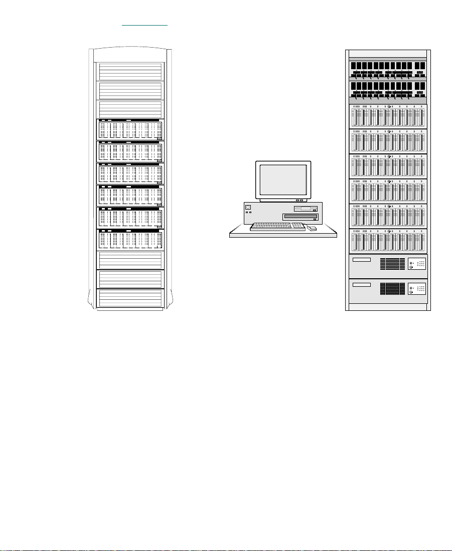
Figure 1-1 shows typical MediaNet rack configurations.
Avid Unity
MediaNet Rack Standard Video Rack
Figure 1-1 Typical MediaNet Rack Configurations
23
Page 24

MediaNet Servers
The MediaNet Server is a PC-compatible system running the
Windows NT for Workstation operating system. It contains either
384 MB or 768 MB of error-correcting (ECC) memory to prevent
corruption of the MediaNet Server data used to maintain, store, and
retrieve media files and audio files.
The MediaNet Server controls user access to the shared storage
subsystem by logging users in through controlled user accounts with
passwords. It also controls which workspaces a user can mount on the
MediaNet client desktop, and whether the user has read or write
access to the files on the workspace. This allows a system
administrator to control a user’s capabilities and to manage the shared
environment, preventing overwriting or damage to shared media files
and audio files.
MEDIArray Enclosures
The MEDIArray enclosures hold the MEDIArray drives that store data
in the MediaNet environment. Each storage subsystem has at least one
MEDIArray enclosure. You can connect up to 10 MEDIArray
enclosures together to expand the capacity of the storage subsystem.
Each enclosure contains:
n
• Up to 10 MEDIArray drives. The MediaNet File Manager software
stripes the drives together to provide increased performance. The
File Manager can support 18-GB 10K MEDIArray drives and 9-GB
MediaShare
One 18-GB 10K MEDIArray drive in the storage subsystem is reserved for
messaging between the MediaNet clients and the MediaNet File Manager.
Other drives can be reserved as spares to use for replacements if drive
problems arise.
™
F/C drives.
24
Page 25
• Two link control cards (LCCs). The LCCs support and control the
Fibre Channel Arbitrated Loop, and monitor the enclosure
environment.
• Two power supplies. Each power supply can support a fully
configured MEDIArray enclosure. The two power supplies
provide automatic power redundancy should one of the power
supplies fail.
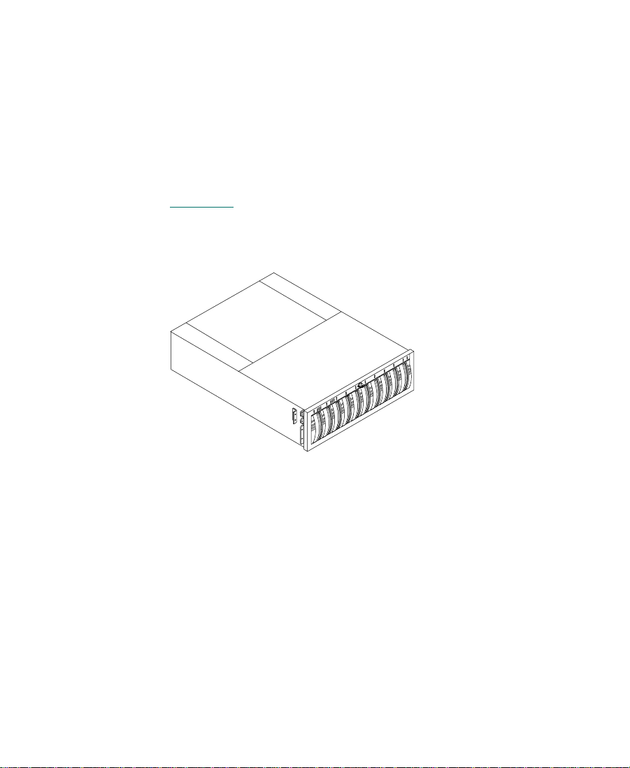
The MEDIArray enclosures are available as rack-mount modules (see
Figure 1-2
standard 19-inch NEMA or EIA rack, and come with a set of mounting
rails to support the MEDIArray enclosure.
). They fit into the optional Avid MediaNet rack or any
Figure 1-2 10-Slot Rack-Mount MEDIArray Enclosure
MediaNet Clients
The MediaNet environment can support both Macintosh-based and
Windows NT-based clients. These systems connect to the shared
storage through the MEDIASwitch. The clients request media files and
audio files through the MediaNet Server, which points them to where
the files are located on the MEDIArray drives.
25
Page 26

The Macintosh-based MediaNet clients can run:
• Media Composer Release 7.2 (Power Macintosh
• Film Composer Release 7.2 (Power Macintosh 9500/9600/G3)
• Media Station Release 7.2 (Power Macintosh 9500/9600/G3)
• Avid Xpress for Macintosh systems Release 2.2 (Power Macintosh
9500/9600/G3)
• Media Composer Release 8.0 or later (Power Macintosh 9600/G3)
• Avid Xpress for Macintosh systems Release 2.5 or later (Power
Macintosh 9600/G3)
The Windows NT-based MediaNet clients can run:
• Avid Symphony Release 2.1 or later (IBM
• Media Composer or Film Composer Release 9.1 or later (IBM
IntelliStation M Pro)
• Avid Xpress for Windows NT systems Release 3.1 or later (IBM
IntelliStation M Pro)
Fibre Channel Adapter Boards
®
9500/9600/G3)
®
IntelliStation® M Pro)
The Avid Unity Fibre Channel adapter board provides a Fibre Channel
interface to the MediaNet environment. This board allows the
MediaNet Server to connect to the storage subsystem, to access the
MEDIArray drives, and to manage and maintain the file system on the
drives in the MEDIArray enclosure through the MEDIASwitch.
Each MediaNet client also needs a Fibre Channel adapter board to
connect to the MEDIASwitch. The board allows the client access to the
storage subsystem and the MediaNet Server through the
MEDIASwitch.
26
Page 27

MediaNet Cables
MediaNet can use two types of cables, copper cable or optical cable, to
connect the MediaNet clients, the MEDIArray enclosures, and the
MediaNet Server to the MEDIASwitch. The connection between the
MediaNet Server and the MEDIASwitch always uses copper cable.
The connection between the MediaNet clients and the MEDIASwitch
can use either copper cable or optical cable.
You can mix copper and optical cables in the MediaNet environment
(that is, you might use optical cable between the MediaNet clients and
the MEDIASwitch, and copper cable between the MEDIASwitch and
the MEDIArray enclosure). However, you cannot mix copper and
optical cables in the same cable run (that is, from the MediaNet client to
the MEDIASwitch, or the MEDIASwitch to the MEDIArray enclosure).
c
You cannot splice two short lengths of MediaNet cable together to
make a longer cable. Cables that run from one point to another (also
known as home-run cables) must be one continuous piece of cable.
If your cables are too short to connect the components in your
MediaNet environment, you’ll need to obtain longer cables.
Copper cables are fully shielded, 75-Ω (ohm), twin-axial Fibre Channel
cables with the shield fully bonded to a DB-9 connector at each end.
They can be used when the distance from the MediaNet client to the
MEDIASwitch does not exceed 99 feet (30 meters). Copper cables must
meet the 1-GBd FC-AL standard, Revision 4.4 or higher. Cable lengths
longer than 33 feet (10 meters) must be equalized.
Optical cables are optional within the MediaNet environment and
customer supplied. They can be either 50-µm 125 (micrometer),
multimode, dual SC duplex cables or 62.5-µm 125 (micrometer),
multimode, dual SC duplex cables. The 50-µm cables can be used for
distances from 3 feet (1 meter) to 1650 feet (500 meters). The 62.5-µm
cables can be used for distances from 3 feet (1 meter) to 575 feet
(175 meters).
27
Page 28

In some configurations when you are using optical cables, you also
need to use media interface adapters (MIAs), at one or both ends of the
cable, to attach the optical cable to the MEDIASwitch or the MediaNet
client.
c
MEDIASwitches
Because of the tight tolerances needed for Fibre Channel cables,
Avid recommends you purchase all of your MediaNet cables either
from Avid or a certified Fibre Channel cable manufacturer. Avid will
not support any MediaNet environment that contains homemade or
uncertified cables.
The MEDIASwitch is a Fibre Channel switch with eight ports. The
MEDIASwitch allows you to connect up to five MediaNet clients and
up to ten MEDIArray enclosures (in groups of two or three enclosures)
together.
The MEDIASwitch isolates its ports, treating each port as an
individual Fibre Channel Arbitrated Loop. This isolation localizes
loop initialization events (adding or removing clients, or client
restarts) to a particular port. The isolation also increases the stability of
the Fibre Channel environment.
All of the connections and indicators are on the back of the
MEDIASwitch. Figure 1-3
and status indicators.
shows the switch’s rear panel connectors
28
Page 29
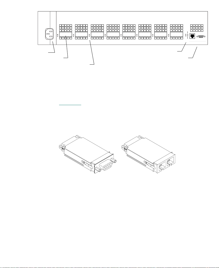
1 2 3 4 5 6 7 8
Enet Act
PWR
Fault
Enet Col
MGMT
10Base-T RS-232
Power connector
GBIC port status indicators
Power and network indicators
GBIC port
Management connectors
Figure 1-3 MEDIASwitch
Each MEDIASwitch port uses a Gigabit Interface Converter (GBIC) to
connect either copper cable or optical cable to the MEDIASwitch (see
Figure 1-4
). The GBICs are removable so that your MEDIASwitch can
be quickly reconfigured to support any combination of copper and
optical cable connections.
9-pin copper GBIC Optical GBIC
Figure 1-4 Gigabit Interface Connectors
n
The front of the copper GBIC has a 9-pin connector. The front of the
optical GBIC has two square connectors, one for the transmit cable and
one for the receive cable.
Avid does not support using MIAs to connect optical cable to a copper GBIC.
29
Page 30

MediaNet Uninterruptible Power Supplies
The MediaNet uninterruptible power supplies provide power
protection when there is a brownout, a power dip or spike, or a power
outage. They shut down the MediaNet File Manager software, the
MEDIASwitch, and the storage subsystem after approximately
8 minutes of power interruption.
n
Avid recommends the use of UPSs to protect the MediaNet clients from
potential data loss if a brownout or power outage occurs. These UPSs must be
purchased separately.
MediaNet Software
The MediaNet File Manager software contains a number of
components for the MediaNet Server and the MediaNet clients to
allow setup, configuration, communication, and data access in the
MediaNet environment.
The MediaNet File Manager software components include:
• The Fibre Channel driver and firmware for the Fibre Channel
• The MediaNet Setup Manager software. It creates and repairs the
• The MediaNet File Manager software. It manages the file system
adapter board. They allow the Fibre Channel adapter board in the
MediaNet Server to access the MEDIArray drives.
drive set that the MediaNet File Manager uses to store media files.
on the drives in the MEDIArray enclosure. It also provides the
communication between the MediaNet clients and the storage
subsystem, allowing access to the MediaNet workspaces.
30
Page 31

The MediaNet client software components include:
• The Fibre Channel driver and firmware for the Fibre Channel
adapter board. They allow the Fibre Channel adapter board in the
MediaNet client to access the MEDIArray drives.
• The MediaNet administration software. It allows you to manage
the file system, create user accounts, and control how users access
the MediaNet workspaces to read and write media files and audio
files.
• The MediaNet client software. It allows users to log into the
shared storage environment to gain access to media files and
audio files.
• Avid application software such as Media Composer. It uses the
media files and audio files available on the shared storage
subsystem.
Configuration Requirements
Both the MediaNet Server and the MediaNet storage subsystem have
requirements you must meet to create a MediaNet environment. The
following sections list the minimum MediaNet client and MediaNet
requirements.
MediaNet Server Requirements
The MediaNet requirements for the MediaNet Server are:
• One Avid-approved PC-compatible system to act as the primary
MediaNet Server
• One display (customer supplied)
• The Windows NT 4.0 Workstation operating system
• Service Pack 5 for the Windows NT 4.0 operating system
31
Page 32

• 384-MB or 768-MB random-access memory
• One Fibre Channel adapter board
• One Avid-approved modem for dial-in support
• MediaNet File Manager software
• Optional, a second MediaNet Server to configure as a backup to
the primary MediaNet Server
MediaNet Storage Subsystem Requirements
The MediaNet requirements for the MediaNet storage subsystem are:
• One or two racks (optional)
• One to four uninterruptible power supplies
• One or ten MEDIArray enclosures
• Up to ten MEDIArray drives for each MEDIArray enclosure
• One or two MEDIASwitches
MediaNet Client Requirements
The MediaNet requirements for the MediaNet for Macintosh clients
are:
• One to nine Macintosh-based MediaNet clients (see “MediaNet
Clients” on page 25 for a list of supported products and
platforms)
®
•Mac
• 256-MB or more random-access memory
• One Fibre Channel adapter board for each MediaNet client
• MediaNet for Macintosh client software for each MediaNet client
• MediaNet administration software
OS 7.6.1, Mac OS 8.1, Mac OS 8.5.1, or Mac OS 8.6
32
Page 33

The MediaNet requirements for the MediaNet for Windows NT clients
are:
• One to nine Windows NT-based MediaNet clients (see “MediaNet
Clients” on page 25 for a list of supported products and
platforms)
• The Windows NT 4.0 Workstation operating system
• Service Pack 5 for the Windows NT 4.0 operating system
• 256-MB or more random-access memory
• One Fibre Channel adapter board for each MediaNet client
• MediaNet for Windows NT client software for each MediaNet
client
• MediaNet administration software
33
Page 34

CHAPTER 2
Installing the MediaNet Server and Storage Subsystem
Installing the Avid Unity MediaNet Server and MediaNet storage
subsystem at your site requires the addition of hardware and software
to create a functioning MediaNet environment. The following sections
describe how to connect the MediaNet Server and MediaNet storage
subsystem hardware.
When you add MediaNet to your site, it connects the MediaNet Server,
MediaNet storage subsystem, and MediaNet clients to a separate Fibre
Channel Arbitrated Loop. This loop requires you to add a Fibre
Channel adapter board to the MediaNet Server and to each MediaNet
client you are connecting to the MediaNet environment.
34
Page 35

Supported Configurations
MediaNet supports several configurations of MediaNet storage and
clients. These configurations allow you to connect up to nine clients to
1.8 TB of MediaNet shared storage (ten MEDIArray enclosures).
Appendix C
and any restrictions or limitations.
provides a description of the MediaNet configurations
Before You Begin
Keep the shipping
boxes that come with
your MediaNet storage
subsystem. You might
need to repackage and
ship the components in
the future.
n
Before you begin to install the MediaNet Server and MediaNet storage
subsystem, do the following:
• Unpack all the MediaNet components.
• Check the contents of the MediaNet kit against the packing sticker
on the outside of each shipping box to confirm you have received
all the components.
After you unpack your MediaNet Server and MediaNet storage
subsystem, make sure it contains:
• One 19-inch rack (optional). You can use the MediaNet rack or a
rack that you supply. If you supply your own rack, it can have
either 120-volt, 15-amp power strips with L5-15 plugs, or 230-volt,
30-amp power strips with IEC C-19 plugs on the ends of the
power cords.
If you have more than six MEDIArray enclosures in your MediaNet
environment, you will need two racks to hold all of the MediaNet
components.
• One or two 120-volt or 230-volt, 30-amp uninterruptible power
supplies.
• One or more rack-mountable MEDIArray enclosures.
• One or two MEDIASwitches.
35
Page 36

• One MediaNet Server (PC-compatible system) with a keyboard
and mouse.
• One display (customer supplied).
• One Fibre Channel adapter board for the MediaNet Server.
• Several MediaNet copper cables.
When you are expanding an existing MediaNet environment, you can
order MEDIArray enclosures and MediaNet clients separately. You
can add them to the existing environment, providing you do not
exceed the limits of the environment.
Installing the MediaNet Server and Storage Subsystem
The MediaNet Server and MediaNet storage subsystem are placed
into a rack for easy access to the cables, connectors, and drives. The
following installation process places the various components into the
rack from bottom to top.
Placing MediaNet Components
When you are setting up your MediaNet storage subsystem:
• Locate the major components (the MEDIASwitch, the MEDIArray
enclosures, and the MediaNet Server) so they can be rack mounted
in a short or tall rack.
n
Avid recommends that you rack mount the MEDIASwitch, the MEDIArray
enclosures, and the optional UPSs. The MediaNet Server can be placed on top
of a short rack or on a table next to a tall rack. Avid provides copper cables to
connect all of these components in a rack.
36
Page 37

• Locate the MediaNet clients within the limits of the type of cable
you are using: 99 feet (30 meters) maximum for copper cables and
1650 feet (500 meters) maximum for optical cables.
You can mix copper and optical cables in the MediaNet
environment (that is, you might use optical cable between some
MediaNet clients and the MEDIASwitch, and copper cable
between other MediaNet clients and the MEDIArray enclosure).
However, you cannot mix copper and optical cables in the same
cable run (that is, from the MediaNet client to the MEDIASwitch).
n
Avid does not support using optical cables to connect the MediaNet Server to
the MEDIArray enclosures.
• Locate the components for each MediaNet client as described in
the Avid Composer Products Setup Guide.
• If you are installing several rack-mount MediaNet MEDIArray
enclosures, make sure you have room in the rack to locate the
MEDIArray enclosures one above the other for cabling
convenience.
37
Page 38

Using the Grounding Wrist Strap
Your MediaNet kit ships with a grounding wrist strap. To prevent any
damage to the MediaNet Server and the MediaNet clients, any of the
peripheral boards, or the system memory, you must wear the
grounding wrist strap when handling the boards.
c
The peripheral boards are sensitive to electrostatic discharge. Do not
handle any of the boards unless you are properly grounded. Put on
the grounding wrist strap and do not take it off until you complete
the board removal and installation.
To use the grounding wrist strap:
1. Make sure the MediaNet Server is plugged into a wall outlet but
not turned on.
2. Put the grounding wrist strap onto your wrist and adjust the
elastic strap to fit your wrist. Open the MediaNet Server, as
described in the documentation that came with the system, and
attach the grounding clip to the power supply.
38
Page 39

Installing the Uninterruptible Power Supplies
Your MediaNet environment comes with one or two 120-volt, or
230-volt, 30-amp uninterruptible power supplies (UPSs). These UPSs
provide protection from power outages by supplying approximately
10 minutes of power to the MediaNet environment so you have time
to shut the environment down gracefully.
c
n
The UPSs are designed to fit into the MediaNet rack and do not ship
with mounting rails. If you supply your own rack, you must provide
additional support for the rear of the UPSs so they do not sag.
To install a UPS:
1. Locate the UPS. You install the UPS at the bottom of the rack.
2. Select the lowest full U-alignment position in the rack where you
can mount the UPS. The UPS uses 4 U (EIA rack units), or 7 inches
of rack space.
3. Slide the UPS into the rack and align the bottom of the UPS at the
midpoint of the rack unit.
4. Locate four screws in the UPS kit.
5. Secure the UPS to the front rails with the screws.
The UPSs have nonstandard plugs and require nonstandard receptacles. The
120-volt UPS has an L5-30 plug and requires an L5-30 receptacle. The
230-volt UPS has an IEC C-20 plug and requires an IEC C-19 receptacle.
6. Plug the UPS into a wall outlet.
7. If you are installing an additional UPS, repeat steps 1 to 6 for the
second UPS.
39
Page 40

Installing the MEDIArray Enclosures
The MEDIArray enclosures hold the MEDIArray drives. Install the
MEDIArray enclosures directly above the UPSs in the rack.
Installing Rack-Mount MEDIArray Enclosure Support Rails
The rack-mount MEDIArray enclosure can be installed in either a
NEMA or an EIA rack. To install the MEDIArray enclosure
rack-mount rails:
1. Locate a pair of MEDIArray enclosure support rails in the
MEDIArray enclosure kit. The rails fit both NEMA and EIA racks.
Figure 2-1
shows one of the MEDIArray enclosure support rails.
n
Figure 2-1 MEDIArray Enclosure Rack-Mount Support Rail
If you are installing the MEDIArray enclosures into the MediaNet rack, the
MediaNet rack kit has several pairs of solid support rails that you should use
instead of the adjustable support rails supplied in the MEDIArray enclosure
kit. The solid support rails should be placed and secured in the same manner
as the adjustable support rails, if they are not already installed. Follow the
appropriate steps in this procedure to install the solid support rails.
40
Page 41

2. Select the lowest full U-alignment position in the rack where you
can mount the MEDIArray enclosure. The MEDIArray enclosure
uses 3.5 U (EIA rack units), or 6 1/8 inches of rack space. Position
the MEDIArray enclosure support rails so the bottom of each rail
is at the baseline of a U-alignment position (see Figure 2-2
).
n
will install 1/2 U filler panels between the MEDIArray enclosures after they
are positioned in the rack.
Rack channel hole spacing
EIA rack unit
Baseline of MEDIArray
enclosure is at
U-alignment position
between two 1/2-inch
spaced holes.
Positioning the MEDIArray enclosure support rails is important because you
1 3/4 in
1 3/4 in
1 3/4 in
3 U
2 U
1 U
Rack front channel
5/8 in
5/8 in
1/2 in
5/8 in
5/8 in
1/2 in
5/8 in
5/8 in
1/2 in
5/8 in
5/8 in
1/2 in
MEDIArray
enclosure
Support rail
Figure 2-2 Locating the MEDIArray Enclosure Rails
3. Loosen the three nuts on the adjustment screws so the rail can be
sized to fit the rack. Do not completely remove the nuts. Leave
them finger tight.
4. Place the left support rail over the rack front channel and the rack
back channel (see Figure 2-3
). The rail ends should be on the
outside of the rack channels.
41
Page 42

5. Locate two screws in the MEDIArray rail kit.
n
Screws
If you are installing the rails in a rack that does not have threaded holes, you
will also need to locate four clip nuts in the rail kit. Slip the clip nuts over the
holes in the rack front and back channels where you will be installing the
screws for the MEDIArray enclosure rails (see Figure 2-3
6. Loosely attach the front of the left MEDIArray enclosure support
rail to the rack front channel with the screws (see Figure 2-3
When the rail is aligned correctly, you are able to use the top and
third holes in the rail to attach it to the rack front channel.
Rack front channel
Support rail
and Figure 2-4).
).
Attaching Clip Nuts
Clip nuts
Figure 2-3 Attaching the MEDIArray Enclosure Rails to the
Rack Front Channel
7. Locate two screws in the MEDIArray rail kit.
42
Page 43

8. Loosely attach the rear of the left MEDIArray enclosure support
rail to the rack back channel with the screws (see Figure 2-4
When the rail is aligned correctly, you are able to use the top and
third holes in the rail to attach it to the rack back channel.
).
Rack back channel
Screws
Support rail
Figure 2-4 Attaching the MEDIArray Enclosure Rails to the
Rack Back Channel
9. Tighten the screws for the left MEDIArray enclosure support rail
at the rack front channel and the rack back channel.
10. Tighten the three nuts on the adjustment screws on the support
rail.
Attaching Clip Nuts
Clip nuts
n
11. Repeat steps 1 to 10 for the right support rail.
12. If you are installing additional rack-mount MEDIArray
enclosures, repeat steps 1 to 11 for each pair of MEDIArray
enclosure support rails.
Make sure you position the next set of support rails approximately 3.5 U
above the bottom of the previous set of support rails. The holes in the rails
should align so you can use the second and bottom holes.
43
Page 44

Placing the MEDIArray Enclosures onto the Rack-Mount Rails
To place a rack-mount MEDIArray enclosure into the rack:
1. Make sure you have installed the rack-mount MEDIArray
enclosure support rails (see “Installing Rack-Mount MEDIArray
Enclosure Support Rails” on page 40). If you are installing several
MEDIArray enclosures, install all the support rails before you
begin to install the MEDIArray enclosures.
2. From the front of the rack, slide a MEDIArray enclosure into the
bottom set of support rails. Push in the MEDIArray enclosure until
the mounting clips on the side of the MEDIArray enclosure touch
the rack front channel (see Figure 2-5
Rack front channel
).
Mounting clip
MEDIArray enclosure
Figure 2-5 Installing a MEDIArray Enclosure
3. Open the front door on the MEDIArray enclosure. If the door is
locked, locate the key in the MEDIArray enclosure kit and unlock
the door (see Figure 2-6
).
44
Page 45

Key
Turn clockwise
to unlock.
Figure 2-6 Opening the MEDIArray Enclosure Front Door
4. Locate two mounting screws in the MediaNet kit.
5. Attach the MEDIArray enclosure to the rack front channel using
MEDIArray enclosure
Front door
one mounting screw on each side of the MEDIArray enclosure (see
Figure 2-7
). The mounting screw should go into the bottom hole in
the mounting clip.
Mounting clip
Mounting screw
Figure 2-7 Installing the MEDIArray Enclosure Mounting
Screws
45
Page 46

6. Close the MEDIArray enclosure front door.
7. If you are installing several rack-mount MEDIArray enclosures,
repeat steps 2 to 6 for each additional MEDIArray enclosure.
Connecting MEDIArray Enclosure Power Cords
Each MEDIArray enclosure has two power cords, one for each power
supply. The power cord connectors are located behind the fan
assembly. To connect the power cords to the power supplies in a
MEDIArray enclosure:
1. Loosen the fan assembly by pinching the latches together.
2. While you keep the latches pinched, slide the fan assembly out of
the MEDIArray enclosure (see Figure 2-8
).
Latches
MEDIArray enclosure
n
Fan assembly
Slide fan assembly out.
Figure 2-8 Removing the MEDIArray Enclosure Fan Assembly
3. Locate two power cords in the MediaNet kit.
If you are installing the MEDIArray enclosures into the MediaNet rack, the
MediaNet rack kit has its own set of power cords with IEC C-21 and
IEC C-22 connectors for the MEDIArray enclosures. Use these power cords
instead of the power cords supplied in the MEDIArray enclosure kit.
46
Page 47

4. Attach one power cord to the power connector in the lower right
of the bottom power supply (see Figure 2-9
cord through the channel below the LCC and out the back of the
MEDIArray enclosure.
MEDIArray enclosure
). Route the power
Power supply
c
LCC
Channel
Power cord
Power switch Power switch
Figure 2-9 Attaching the MEDIArray Enclosure Power Cords
5. Attach the other power cord to the power connector in the upper
left of the top power supply (see Figure 2-9
down the side of the LCC to the channel below the LCC and out
the back of the MEDIArray enclosure.
Make sure that both power cords do not interfere with the
installation of the fan assembly. The cords must be properly routed
into the channels below the LCCs before the fan assembly is
reinstalled.
Channel
). Route the power cord
Power supply
n
6. Check to make sure that the MEDIArray enclosure power switches
are on (see Figure 2-9
By default, each MEDIArray enclosure ships with the power switch in the on
position. Check the power switches to make sure they are on.
).
47
Page 48

MEDIArray enclosure
7. Replace the fan assembly by pinching the latches together and
sliding the assembly into the back of the MEDIArray enclosure
(see Figure 2-10
).
Latches
Fan assembly
Slide fan assembly in.
Figure 2-10 Replacing the MEDIArray Enclosure Fan Assembly
8. Repeat steps 1 to 7 for each MEDIArray enclosure in your
MediaNet storage subsystem.
9. Plug the power cords from the right side of each MEDIArray
enclosure into a power strip on the right of the rack.
10. Plug the power cords from the left side of each MEDIArray
enclosure into a power strip on the left of the rack.
Installing MEDIArray Drives
The MEDIArray enclosures ship with only two drives installed in slots
0 and 1 (the slot numbers appear above each slot and are numbered
from left to right). The remaining slots are filled with dummy drives to
help provide proper airflow within the MEDIArray enclosure. You
will need to remove some or all of the dummy drives and replace them
with MEDIArray drives. The additional MEDIArray drives are
shipped separately from the MEDIArray enclosure and must be
installed in the MEDIArray enclosure.
48
Page 49

c
Make sure you are wearing a grounding wrist strap and that it is
attached to the rack assembly before you remove or add any drives
in the MEDIArray enclosure.
n
c
MEDIArray enclosure
If you are attaching MEDIArray enclosures with 9-GB MediaShare F/C
drives, you must keep the 9-GB MediaShare F/C drives separate from any
18-GB 10K MEDIArray drives that you have in other MEDIArray
enclosures. You cannot mix 9-GB MediaShare F/C drives and 18-GB 10K
MEDIArray drives in the same MEDIArray enclosure. See Appendix C
more information on using 9-GB MediaShare F/C drives.
To install the drives:
1. Open the front door on the MEDIArray enclosure (see Figure 2-6
2. Starting with slot 2, remove as many dummy drives as you have
MEDIArray drives in the drive kit. Push the latch on the dummy
drive, grab the handle, and slide it out of the MEDIArray
enclosure (see Figure 2-11
If you are not filling the MEDIArray enclosure with 10 MEDIArray
drives, leave the dummy drives in any unused slots to provide
proper airflow within the MEDIArray enclosure.
for
).
).
Dummy drive
Latch
Handle
Figure 2-11 Removing a Dummy Drive from the MEDIArray
Enclosure
49
Page 50

3. Locate a MEDIArray drive in the MEDIArray drive kit.
4. Remove the MEDIArray drive from the antistatic bag.
c
MEDIArray enclosure
Be careful when you are handling the MEDIArray drives. They
contain open components that can be damaged if the drive is hit or
dropped.
5. Grasp the drive assembly by the handle.
6. Align the drive assembly with the guides in the MEDIArray
enclosure (see Figure 2-12
Figure 2-12 Inserting a Drive into the MEDIArray Enclosure
7. Gently slide the drive into the MEDIArray enclosure until the
latch engages to lock the drive assembly in place. You should hear
the latch click when it engages.
).
Drive assembly
Latch
Handle
8. Repeat steps 1 to 7 for each drive you are installing into the
MEDIArray enclosure.
50
Page 51

You might need to use a
pen or a paper clip to
push the + and –
buttons to change the
MEDIArray enclosure
ID.
Setting MEDIArray Enclosure IDs
Each MEDIArray enclosure needs a unique enclosure ID to identify
the MEDIArray enclosure and determine its drive addresses. The
enclosure IDs must be between one and eleven (1 and 11) and the IDs
must be in sequential order. To set the MEDIArray enclosure IDs:
1. Open the front door on all the MEDIArray enclosures in the rack.
2. Locate the enclosure ID switch on the MEDIArray enclosure front
panel (see Figure 2-13
).
3. Use the + (plus) button to increment the MEDIArray enclosure ID
or the – (minus) button to decrement the MEDIArray enclosure ID.
4. Starting with the MEDIArray enclosure that is lowest in the rack,
set the ID to 1.
Enclosure ID switch
3
Enclosure ID lights
0
1
0
2
3
Drive
activity
lights
10
8
6
11
9
7
4
1
5
Decrement ID
2
2
Increment ID
2
Figure 2-13 Setting the MEDIArray Enclosure ID
5. Move up to the next MEDIArray enclosure and set the ID to 2.
6. Continue setting the MEDIArray enclosure IDs by moving up to
the next MEDIArray enclosure and incrementing the ID number
by one from the previous enclosure’s ID number.
51
Page 52

7. Repeat step 6 until all of the MEDIArray enclosure IDs are set. The
last ID number should be 6.
8. When you have all the MEDIArray enclosure IDs set, close all the
MEDIArray enclosure front doors.
Installing a MEDIASwitch
The MEDIASwitch connects the MediaNet storage subsystem to a
maximum of nine MediaNet clients. It allows the MediaNet clients to
use the storage simultaneously, and prevents interruptions by
allowing other systems in the environment to continue working if one
or more systems go offline.
The MEDIASwitch mounts in a rack above the MEDIArray enclosures.
You should leave a 1 U space (1 3/4 inches) below the MEDIASwitch
to allow cables to be run to the MEDIASwitch later. If you have two
MEDIASwitches, mount them with no space between the
MEDIASwitch enclosures.
Installing the Rack-Mount Shelf
The rack-mount shelf supports the MEDIASwitch when it is mounted
in a rack. If you are installing more than one MEDIASwitch, you can
stack them on the shelf in your rack. To install the rack-mount shelf:
1. Locate the shelf in the rack-mount shelf kit.
2. Remove the four nuts that hold each adjustable ear to each side of
the shelf. Set the nuts and adjustable ears aside (see Figure 2-14
52
).
Page 53

Adjustment studs and nuts
Adjustable ears
Figure 2-14 Rack-Mount Shelf
3. Select a position in the rack where you can mount the shelf. The
shelf requires 2 U (EIA rack units) or 3 1/2 inches of rack space.
Position the shelf so the bottom mounting holes in the shelf front
ears align with the bottom hole for a U-alignment (see
Figure 2-15
).
Rack channel hole spacing
1 3/4 in
1 3/4 in
EIA rack unit
Figure 2-15 Locating the Rack-Mount Shelf
4. Loosely attach the shelf front ears to the rack front channels with
the screws provided in the kit (see Figure 2-16
2 U
1 U
1/2 in
5/8 in
5/8 in
1/2 in
5/8 in
5/8 in
1/2 in
Rack front channel
Shelf
Baseline of shelf is at U-alignment
position between two 1/2-inch holes.
).
53
Page 54

n
If you are installing the shelf in a rack that does not have threaded holes, you
will also need to locate four clip nuts in the shelf kit. Slip the clip nuts over
the holes in the rack front channels where you will be installing the screws for
the shelf (see Figure 2-16
).
Attaching Clip Nuts
Clip nuts
Shelf rear
adjustable ears
Rack back channel
Mounting screws
Shelf front ears
Rack front channel
Adjustment studs
and nuts
Figure 2-16 Attaching the Rack-Mount Shelf
5. Locate the adjustable ears and nuts.
6. Slide one adjustable ear onto each side of the rear of the rack and
position the ears so the studs are in the adjustment slots on each
side of the shelf. Loosely attach the nuts to the adjustment studs.
7. Position the back of the shelf so the bottom mounting holes in the
adjustable ears align with the bottom hole for a U-alignment (see
Figure 2-15
). Make sure the shelf is level from front-to-back and
side-to-side.
8. Loosely attach the adjustable ears to the rack back channels with
the screws provided in the kit (see Figure 2-16
).
9. Tighten the nuts on the studs.
10. Tighten all the screws to the rack channels.
54
Page 55

Mounting the MEDIASwitch
The MEDIASwitch sits on the shelf in the rack. To install the
MEDIASwitch:
1. Locate the MEDIASwitch in the MEDIASwitch kit.
2. Position the MEDIASwitch on the shelf with the connectors on the
back of the MEDIASwitch facing the front of the rack. Set the
MEDIASwitch approximately 2 inches (5 cm) back from the front
edge of the shelf (see Figure 2-17
Rack-mount shelf
).
MEDIASwitch
n
MEDIASwitch back panel
Front of rack
Figure 2-17 Mounting the MEDIASwitch
3. Locate the power cord in the MEDIASwitch kit.
If you are installing the MEDIASwitch into the MediaNet rack, the
MediaNet rack kit has its own set of power cords with IEC C-21 and
IEC C-22 connectors for the MEDIASwitch. Use these power cords instead of
the power cords supplied in the MEDIASwitch kit.
55
Page 56

4. Plug one end of the power cord into the power connector on the
MEDIASwitch back panel.
5. Plug the other end of the power cord into a power strip in the back
of the rack.
6. If your configuration has more than one MEDIASwitch, repeat
steps 1 to 5 for the second MEDIASwitch. Stack the second
MEDIASwitch on top of the first MEDIASwitch.
Installing the MediaNet Server
The MediaNet Server controls the files on the MediaNet storage
subsystem and also controls MediaNet client access to the files. As
determined by your MediaNet configuration, you can install the
MediaNet Server in the rack for some small configurations or beside
the rack for a full 10 MEDIArray enclosure configuration.
The MediaNet Server ships with a Fibre Channel adapter board and a
modem installed. It also has an autoselecting power supply that sets
the voltage correctly for either 120 volts or 230 volts.
Before you place the MediaNet Server, you need to add the MediaNet
application key.
Adding the MediaNet Application Key
The application key (frequently called a dongle) determines how many
MediaNet clients can simultaneously use your MediaNet
environment.
c
Be careful not to lose the application key. Your MediaNet
environment does not function without it. If you lose the
application key, you must purchase another one from Avid to use
your MediaNet software.
56
Page 57

To connect the application key to your MediaNet Server:
1. Locate the application key in the MediaNet kit.
2. Attach the application key to the parallel/printer port on the
MediaNet Server. Secure the application key with the
thumbscrews that are part of the key.
c
Do not disconnect the MediaNet application key while the
MediaNet File Manager software is running. This can damage the
application key and render your MediaNet environment unusable
until you purchase a new application key. Contact Avid Customer
Support for assistance.
Installing the Keyboard Shelf (Optional)
When you have a MediaNet configuration that does not completely fill
the MediaNet rack, locate the optional keyboard shelf to hold the
keyboard at approximately waist level.
To mount the keyboard shelf:
1. Position the keyboard shelf at approximately waist level or a
comfortable typing height on the front rack rails.
2. Mount the keyboard shelf using the instructions that are in the
keyboard shelf kit.
Placing the MediaNet Server and Keyboard
Determine where you are locating the MediaNet Server and keyboard.
• If you have a configuration that does not use all of the available
rack space, see “In the Rack” on page 58
• If you have a configuration that uses all of the available rack
space, see “Next to the Rack” on page 58
57
.
.
Page 58

In the Rack
To place the keyboard and MediaNet Server:
1. Place the keyboard on the keyboard shelf.
2. Run the keyboard cable off the back of the shelf.
3. Place the MediaNet Server on top of the MEDIASwitch.
4. Place the MediaNet Server display on top of the MediaNet Server.
Next to the Rack
To place the MediaNet Server and keyboard:
1. Place the MediaNet Server on a table next to the rack. Leave 6 to 8
inches (15 to 20 cm) in front of the MediaNet Server for the
keyboard.
2. Place the keyboard on the table in front of the MediaNet Server.
3. Run the keyboard cable to the back of the MediaNet Server.
4. Place the MediaNet Server display on top of the MediaNet Server.
Connecting the MediaNet Server Cables
n
To connect the MediaNet Server cables:
1. Connect the cables for the display, keyboard, mouse, and power
cords to the MediaNet Server as described in the user’s guide that
came with the system.
If you are installing the MediaNet Server into the MediaNet rack, the
MediaNet rack kit has its own set of power cords with IEC C-21 and
IEC C-22 connectors for the MediaNet Server and display. Use these power
cords instead of the power cords supplied in the MediaNet Server kit.
2. Plug the power cords into a power strip in the back of the rack.
58
Page 59

MEDIASwitch Port Requirements
Avid has specific requirements for placing GBICs into the
MEDIASwitch ports.
MediaNet Port Requirements
In the MediaNet environment, the MEDIASwitch is configured for five
system ports (PORTs 1 to 5) and three storage ports (PORTs 6 to 8) (see
). The system ports can use either copper (9-pin) or optical
Four hosts and
four groups of
MEDIArray
enclosures
Figure 2-18
GBICs. The storage ports must use copper GBICs.
You can connect one MediaNet client to each system port. You can
connect up to two MEDIArray enclosures to each storage port. If you
have more than three MEDIArray enclosures, you will need to daisy
chain the enclosures to the MEDIASwitch ports (see “Connecting
Cables to the MEDIArray Enclosure” on page 61).
1 2 3 4 5 6 7 8
Enet Act
PWR
Fault
Enet Col
MGMT
10Base-T RS-232
Five hosts and
three groups of
MEDIArray
enclosures
System ports
Copper or optical GBICs
1 2 3 4 5 6 7 8
System ports
Copper or optical GBICs
Storage ports
Copper GBICs only
Storage ports
Copper GBICs only
Figure 2-18 MEDIASwitch Port Layout
59
Enet Act
PWR
Fault
Enet Col
MGMT
10Base-T RS-232
Page 60

Installing GBICs
Each MEDIASwitch ships with up to eight GBICs. The GBICs allow
you to attach cables from the Avid systems and the MEDIArray
enclosures to the MEDIASwitch. To install the GBICs into the
MEDIASwitch:
1. Locate a GBIC in the MEDIASwitch kit.
2. Position a GBIC in front of a MEDIASwitch port (see Figure 2-19
Make sure the 9-pin connector or the optical connectors are facing
away from the MEDIASwitch.
Figure 2-19 Installing a GBIC
3. Slide the GBIC into the MEDIASwitch port. You should hear the
retainer clips click when they engage the port.
4. Repeat steps 1 to 3 for each GBIC.
).
60
Page 61

Connecting Cables to the MEDIArray Enclosure
Each MEDIArray enclosure has two LCCs. In some configurations,
one LCC connects the MediaNet storage subsystem to the
MEDIASwitch. The other LCC connects the MediaNet Server to the
MediaNet storage subsystem. In other configurations, both LCCs
connect the MediaNet storage subsystem to the two MEDIASwitches,
and the MediaNet Server connects to a MEDIASwitch port.
Figure 2-20
MEDIArray enclosure. See Appendix C
configuration and how to connect the MediaNet storage subsystem
and MediaNet Server to the MEDIASwitches.
shows the locations of the LCCs on the rear of the
to determine your
EXP connector
PRI connector
LCC A
Power supplies
behind fan
LCC B
Figure 2-20 MEDIArray Enclosure Connection Locations
Each LCC has two connectors: the primary (PRI) connector and the
expansion (EXP) connector (see Figure 2-20
). The PRI connector is the
IN port on the LCC and it accepts data from a host or another LCC
when two MEDIArray enclosures are daisy chained together. The EXP
connector is the OUT port on the LCC and is used to pass data to the
IN port on the next LCC when two MEDIArray enclosures are daisy
chained together.
61
Page 62

You connect the MEDIArray enclosures to the MEDIASwitch either
individually or in groups of two, three, or four MEDIArray enclosures.
The number of MEDIArray enclosures and MediaNet clients that you
have in your environment, and the type of work that the clients will
do, determine how you need to connect the MEDIArray enclosures to
the MEDIASwitch. You typically connect several groups of
MEDIArray enclosures, up to the maximum of 10, to the
MEDIASwitch.
If you have:
• One MEDIArray enclosure, see “Connecting One MEDIArray
Enclosure” on page 63 for cabling instructions.
• A daisy chain of two MEDIArray enclosures, see “Connecting a
Daisy Chain of Two MEDIArray Enclosures” on page 65 for
cabling instructions.
• A daisy chain of three MEDIArray enclosures, see “Connecting a
Daisy Chain of Three MEDIArray Enclosures” on page 68 for
cabling instructions.
• A daisy chain of four MEDIArray enclosures, see “Connecting a
Daisy Chain of Four MEDIArray Enclosures” on page 71 for
cabling instructions.
62
Page 63

Connecting One MEDIArray Enclosure
When you have one MEDIArray enclosure in your MediaNet
environment, you connect it directly to the MEDIASwitch (see
Figure 2-21
).
MEDIASwitch
MEDIArray
enclosure
#1
Cables
Figure 2-21 Cabling for One MEDIArray Enclosure
To connect the MEDIArray enclosure:
1. Locate a 10-foot (3-meter) MediaNet copper cable in the MediaNet
kit. Look for a cable with a 9-pin connector on each end.
2. Attach the 9-pin connector on one end of the cable to the PRI 9-pin
connector on LCC A on the back of MEDIArray enclosure #1 (see
Figure 2-22
). Secure the cable with the thumbscrews on the cable
connector.
63
Page 64

LCC A
9-pin connector
PRI connector
Copper cable
Figure 2-22 Attaching Copper Cable to LCC A
3. Route the cable up the back of the rack and across the top
MEDIArray enclosure to the front of the rack.
4. Attach the 9-pin connector on the other end of the cable to any of
the MEDIASwitch PORTs 5 through 8 (see Figure 2-23
). Secure the
cable with the thumbscrews on the cable connector.
MEDIASwitch ports 5 to 8
Enet Act
1 2 3 4 5 6 7 8
PWR
Fault
Enet Col
MGMT
10Base-T RS-232
To MEDIArray enclosures
Figure 2-23 Cabling to a MEDIASwitch PORT
64
Page 65

Connecting a Daisy Chain of Two MEDIArray Enclosures
When you have multiple MEDIArray enclosures in your MediaNet
environment, you can create daisy chains of two MEDIArray
enclosures to connect to the MEDIASwitch (see Figure 2-24
MEDIASwitch
MEDIArray
enclosures
#2
#1
Cables
Daisy-chain cable
).
Figure 2-24 Cabling for Up to Four MEDIArray Enclosures
To connect the MEDIArray enclosures:
1. Locate a 10-foot (3-meter) MediaNet copper cable in the MediaNet
kit. Look for a cable with a 9-pin connector on each end.
2. Attach the 9-pin connector on one end of the cable to the PRI 9-pin
connector on LCC A on the back of MEDIArray enclosure #1 (see
Figure 2-25
). Secure the cable with the thumbscrews on the cable
connector.
65
Page 66

LCC A
9-pin connector
PRI connector
Copper cable
Figure 2-25 Attaching Copper Cable to LCC A
3. Route the cable up the back of the rack and across the top
MEDIArray enclosure to the front of the rack.
4. Attach the 9-pin connector on the other end of the cable to any of
the MEDIASwitch PORTs 5 through 8 (see Figure 2-26
). Secure the
cable with the thumbscrews on the cable connector.
MEDIASwitch ports 5 to 8
Enet Act
1 2 3 4 5 6 7 8
PWR
Fault
Enet Col
MGMT
10Base-T RS-232
To MEDIArray enclosures
Figure 2-26 Cabling to a MEDIASwitch PORT
5. Locate a 1-foot (0.3-meter) MediaNet copper cable in the
MEDIArray kit. Look for a cable with a 9-pin connector on each
end.
66
Page 67

6. Attach the 9-pin connector on one end of the cable to the EXP
9-pin connector on LCC A on the back of MEDIArray enclosure #1
(see Figure 2-27
). Secure the cable with the thumbscrews on the
cable connector.
7. Attach the 9-pin connector on the other end of the cable to the PRI
9-pin connector on LCC A on the back of MEDIArray enclosure #2
(see Figure 2-27
). Secure the cable with the thumbscrews on the
cable connector.
LCC A
9-pin connector
MEDIArray enclosure #2
MEDIArray enclosure #1
Copper cable
PRI connector
LCC A
EXP connector
Figure 2-27 Daisy Chaining MEDIArray Enclosures
67
Page 68

Connecting a Daisy Chain of Three MEDIArray Enclosures
When you have multiple MEDIArray enclosures in your MediaNet
environment, you can create daisy chains of three MEDIArray
enclosures to connect to the MEDIASwitch (see Figure 2-28
MEDIASwitch
#3
).
MEDIArray
enclosures
#2
#1
Cables
Daisy-chain cable
Figure 2-28 Cabling for Up to Six MEDIArray Enclosures
To connect the MEDIArray enclosures:
1. Locate a 10-foot (3-meter) MediaNet copper cable in the MediaNet
kit. Look for a cable with a 9-pin connector on each end.
2. Attach the 9-pin connector on one end of the cable to the PRI 9-pin
connector on LCC A on the back of MEDIArray enclosure #1 (see
Figure 2-29
). Secure the cable with the thumbscrews on the cable
connector.
68
Page 69

LCC A
9-pin connector
PRI connector
Copper cable
Figure 2-29 Attaching Copper Cable to LCC A
3. Route the cable up the back of the rack and across the top
MEDIArray enclosure to the front of the rack.
4. Attach the 9-pin connector on the other end of the cable to any of
the MEDIASwitch PORTs 5 through 8 (see Figure 2-30
). Secure the
cable with the thumbscrews on the cable connector.
MEDIASwitch ports 5 to 8
Enet Act
1 2 3 4 5 6 7 8
PWR
Fault
Enet Col
MGMT
10Base-T RS-232
To MEDIArray enclosures
Figure 2-30 Cabling to a MEDIASwitch PORT
5. Locate a 1-foot (0.3-meter) MediaNet copper cable in the
MEDIArray kit. Look for a cable with a 9-pin connector on each
end.
69
Page 70

6. Attach the 9-pin connector on one end of the cable to the EXP
9-pin connector on LCC A on the back of MEDIArray enclosure #1
(see Figure 2-31
). Secure the cable with the thumbscrews on the
cable connector.
7. Attach the 9-pin connector on the other end of the cable to the PRI
9-pin connector on LCC A on the back of MEDIArray enclosure #2
(see Figure 2-31
). Secure the cable with the thumbscrews on the
cable connector.
LCC A
9-pin connector
MEDIArray enclosure #2
MEDIArray enclosure #1
Copper cable
PRI connector
LCC A
EXP connector
Figure 2-31 Daisy Chaining MEDIArray Enclosures
8. Locate another 1-foot (0.3-meter) MediaNet copper cable in the
MEDIArray kit. Look for a cable with a 9-pin connector on each
end.
9. Attach the 9-pin connector on one end of the cable to the EXP
9-pin connector on LCC A on the back of MEDIArray enclosure
#2. Secure the cable with the thumbscrews on the cable connector.
10. Attach the 9-pin connector on the other end of the cable to the PRI
9-pin connector on LCC A on the back of MEDIArray enclosure
#3. Secure the cable with the thumbscrews on the cable connector.
70
Page 71

Connecting a Daisy Chain of Four MEDIArray Enclosures
When you have multiple MEDIArray enclosures in your MediaNet
environment, you can create daisy chains of four MEDIArray
enclosures to connect to the MEDIASwitch (see Figure 2-32
MEDIASwitch
#4
MEDIArray
enclosures
#3
#2
#1
Cables
Daisy-chain cable
).
Figure 2-32 Cabling for Up to Eight MEDIArray Enclosures
To connect the MEDIArray enclosures:
1. Locate a 10-foot (3-meter) MediaNet copper cable in the MediaNet
kit. Look for a cable with a 9-pin connector on each end.
2. Attach the 9-pin connector on one end of the cable to the PRI 9-pin
connector on LCC A on the back of MEDIArray enclosure #1 (see
Figure 2-33
). Secure the cable with the thumbscrews on the cable
connector.
71
Page 72

LCC A
9-pin connector
PRI connector
Copper cable
Figure 2-33 Attaching Copper Cable to LCC A
3. Route the cable up the back of the rack and across the top
MEDIArray enclosure to the front of the rack.
4. Attach the 9-pin connector on the other end of the cable to any of
the MEDIASwitch PORTs 5 through 8 (see Figure 2-34
). Secure the
cable with the thumbscrews on the cable connector.
MEDIASwitch ports 5 to 8
Enet Act
1 2 3 4 5 6 7 8
PWR
Fault
Enet Col
MGMT
10Base-T RS-232
To MEDIArray enclosures
Figure 2-34 Cabling to a MEDIASwitch PORT
5. Locate a 1-foot (0.3-meter) MediaNet copper cable in the
MEDIArray kit. Look for a cable with a 9-pin connector on each
end.
72
Page 73

6. Attach the 9-pin connector on one end of the cable to the EXP
9-pin connector on LCC A on the back of MEDIArray enclosure #1
(see Figure 2-35
). Secure the cable with the thumbscrews on the
cable connector.
7. Attach the 9-pin connector on the other end of the cable to the PRI
9-pin connector on LCC A on the back of MEDIArray enclosure #2
(see Figure 2-35
). Secure the cable with the thumbscrews on the
cable connector.
LCC A
9-pin connector
MEDIArray enclosure #2
MEDIArray enclosure #1
Copper cable
PRI connector
LCC A
EXP connector
Figure 2-35 Daisy Chaining MEDIArray Enclosures
8. Locate another 1-foot (0.3-meter) MediaNet copper cable in the
MEDIArray kit. Look for a cable with a 9-pin connector on each
end.
9. Attach the 9-pin connector on one end of the cable to the EXP
9-pin connector on LCC A on the back of MEDIArray enclosure
#2. Secure the cable with the thumbscrews on the cable connector.
10. Attach the 9-pin connector on the other end of the cable to the PRI
9-pin connector on LCC A on the back of MEDIArray enclosure
#3. Secure the cable with the thumbscrews on the cable connector.
73
Page 74

11. Locate another 1-foot (0.3-meter) MediaNet copper cable in the
MEDIArray kit. Look for a cable with a 9-pin connector on each
end.
12. Attach the 9-pin connector on one end of the cable to the EXP
9-pin connector on LCC A on the back of MEDIArray enclosure
#3. Secure the cable with the thumbscrews on the cable connector.
13. Attach the 9-pin connector on the other end of the cable to the PRI
9-pin connector on LCC A on the back of MEDIArray enclosure
#4. Secure the cable with the thumbscrews on the cable connector.
Connecting to Two MEDIASwitches
When you have two MEDIASwitches in your environment, you need
to connect cables from LCC A on the MEDIArray enclosures to the
first MEDIASwitch and from LCC B on the MEDIArray enclosures to
the second MEDIASwitch (see Figure 2-36
). After you have connected
the cables between LCC A on the MEDIArray enclosures and the first
MEDIASwitch, repeat the cabling for the same number of MEDIArray
enclosures. This time connect the cables from LCC B on the
MEDIArray enclosures and PORTs 5 through 8 on the second
MEDIASwitch.
MEDIASwitch 1
MEDIArray
enclosures
Daisy-chain cable
Cables
MEDIASwitch 2
Figure 2-36 Two MEDIASwitch to MEDIArray Enclosure Cabling
74
Page 75

Connecting Cables to the MediaNet Server
The configuration you are creating determines whether you connect
the MediaNet Server directly to the MEDIArray enclosures or to a port
on the first or second MEDIASwitch. See Appendix C
how to connect the MediaNet Server.
• If your configuration recommends connecting to the MEDIArray
enclosures, continue with “Connecting the MediaNet Server to
the MEDIArray Enclosures” on page 75.
• If your configuration recommends connecting to a MEDIASwitch,
continue with “Connecting the MediaNet Server to a
MEDIASwitch” on page 78.
Connecting the MediaNet Server to the MEDIArray Enclosures
When you connect the MediaNet Server to the MEDIArray enclosures,
you attach it directly to the first MEDIArray enclosure and create a
daisy chain to the other MEDIArray enclosures in the environment
(see Figure 2-37
).
to determine
MEDIArray MediaNet
enclosures
Server
Figure 2-37 MEDIArray Enclosure to MediaNet Server Cabling
75
Page 76

To connect the MediaNet Server to the MEDIArray enclosures:
1. Locate a 10-foot (3-meter) MediaNet copper cable in the MediaNet
kit. Look for a cable with a 9-pin connector on each end.
2. Attach the 9-pin connector on one end of the cable to the 9-pin
connector on the Fibre Channel adapter board in the MediaNet
Server (see Figure 2-38
). Secure the cable with the thumbscrews on
the cable connector.
LEDs
Fibre Channel adapter board
Figure 2-38 Attaching Copper Cable to the Fibre Channel
9-pin connector
MediaNet copper cable
Adapter Board
3. Attach the 9-pin connector on the other end of the cable to the PRI
9-pin connector on LCC B of the bottom MEDIArray enclosure in
the rack.
4. Locate a 1-foot (0.3-meter) MediaNet copper cable in the
MEDIArray kit. Look for a cable with a 9-pin connector on each
end.
76
Page 77

Second
MEDIArray
enclosure
First
MEDIArray
enclosure
5. Attach the 9-pin connector on one end of the cable to the EXP
9-pin connector on LCC B on the back of the first MEDIArray
enclosure (see Figure 2-39
). Secure the cable with the thumbscrews
on the cable connector.
9-pin connector
PRI connector
EXP connector
LCC B
Copper cable
Figure 2-39 Attaching the Daisy-Chain Cable to LCC B
6. Attach the 9-pin connector on the other end of the cable to the PRI
9-pin connector on LCC B on the back of the second MEDIArray
enclosure (see Figure 2-39
). Secure the cable with the thumbscrews
on the cable connector.
7. Repeat steps 2 to 6 for the remaining MEDIArray enclosures in the
rack. Leave the EXP connector on the last MEDIArray enclosure
open.
8. After daisy chaining several MEDIArray enclosures, your cabling
should be similar to Figure 2-40
77
.
Page 78

To next MEDIArray enclosure
Daisy-chain cable
Second MEDIArray enclosure
To MediaNet Server
First MEDIArray enclosure
Figure 2-40 MEDIArray Enclosure Daisy Chain
Connecting the MediaNet Server to a MEDIASwitch
When you connect the MediaNet Server to a MEDIASwitch, you
attach it to an available switch port that is capable of accepting a host
connection (see Figure 2-41
). See Appendix C to determine which
MEDIASwitch host file you will be using for your configuration.
MediaNet Server
MEDIASwitch
Cable
Figure 2-41 MEDIASwitch to MediaNet Server Cabling
78
Page 79

To connect the MediaNet Server to a MEDIASwitch:
1. Locate a 10-foot (3-meter) MediaNet copper cable in the MediaNet
kit. Look for a cable with a 9-pin connector on each end.
2. Attach the 9-pin connector on one end of the cable to the 9-pin
connector on the Fibre Channel adapter board in the MediaNet
Server (see Figure 2-42
). Secure the cable with the thumbscrews on
the cable connector.
LEDs
Fibre Channel adapter board
9-pin connector
MediaNet copper cable
Figure 2-42 Attaching Copper Cable to the Fibre Channel
Adapter Board
3. Attach the 9-pin connector on the other end of the cable to PORT 5
on the second MEDIASwitch (see Figure 2-43
). Secure the cable
with the thumbscrews on the cable connector.
Host ports
Enet Act
1 2 3 4 5 6 7 8
PWR
Fault
Enet Col
MGMT
10Base-T RS-232
To MediaNet Server
Figure 2-43 Cabling the MediaNet Server to a MEDIASwitch
79
Page 80

Connecting the MEDIASwitch MGMT Port
You need to connect the MEDIASwitch to the Ethernet connector on
the MediaNet Server so you can update and check the MEDIASwitch
configuration. To connect the MEDIASwitch to the MediaNet Server:
1. Locate the Ethernet crossover cable in the MediaNet kit. The cable
is red and has an RJ-45 connector on each end.
2. Plug one end of the cable into the Ethernet connector on the back
of the MediaNet Server.
3. Route the cable under the MEDIASwitch to the front of the rack.
4. Plug the other end of the cable into the MGMT 10BASE-T port on
the MEDIASwitch.
n
If you have two MEDIASwitches, you can move the crossover cable from one
MEDIASwitch to the other when you need to update or check the
MEDIASwitches.
80
Page 81

Turning On the MediaNet Environment
When you finish connecting all the MediaNet Server and storage
subsystem hardware, you can start the MediaNet environment.
Turn on the power to the MediaNet Server and storage subsystem
components in the following order:
1. Turn on each UPS. The power switch is on the back of the UPS.
The MEDIArray enclosure power switches are normally
inaccessible, behind the fan assembly in each MEDIArray
enclosure (you turned the MEDIASwitches on when you
connected the power cord adapters earlier). The MEDIArray
enclosures turn on with the UPSs. You’ll see the lights on each
MEDIArray enclosure turn on. They will flash for up to 2 minutes
while each drive in each MEDIArray enclosure spins up to
operating speed.
n
The lights above the drives in the MEDIArray enclosure flash until the drives
reach operating speed. The MEDIArray enclosure is ready when the lights
above all the drives are on and not flashing.
The MEDIASwitches also have no power switch and turn on with
the UPSs.
2. Turn on the MediaNet Server display. The power switch is on the
front of the display.
3. Turn on the MediaNet Server. The server has two power switches;
one on the power supply on the rear of the server, and the other on
the front of the server. Both switches need to be turned on for the
server to operate.
81
Page 82

CHAPTER 3
Installing the MediaNet Server Software
The Avid Unity MediaNet Server uses a number of software
components to create a functioning MediaNet environment. If you are
missing any of these components, your MediaNet environment will
not work correctly. The following sections describe how to install
software on the MediaNet Server that is part of a MediaNet
environment. Installing all the MediaNet software is a multistep
process. Make sure you complete the sections in sequential order.
c
If you fail to install the software in the order described, you might
miss or overwrite several of the software components you need to
create a functioning MediaNet environment.
82
Page 83

Installing Windows NT Workstation 4.0 (Optional)
The MediaNet Server uses the Windows NT Workstation 4.0 operating
system and Service Pack 5 to set up and manage the drives that are
part of the storage subsystem. The MediaNet Server uses the default
Windows NT installation that comes preinstalled on the system’s hard
drive.
To determine the version of the Windows NT operating system
installed on the MediaNet Server:
1. Click the Start button, point to Programs, point to Administrative
Tools, and then select Windows NT Diagnostics. The Windows NT
Diagnostics window opens.
2. Click the Version tab. The version of the Windows NT operating
system installed on the MediaNet Server appears below the
Windows icon.
83
Page 84

3. If your MediaNet Server does not have the Windows NT
Workstation 4.0 operating system or Service Pack 5 installed, you
will need to install either the Windows NT operating system, the
service pack, or both.
When you reinstall the Windows NT operating system for any
reason, make sure you perform a default installation (accept all the
standard installation recommendations) of the Windows NT
Workstation 4.0 operating system. Follow the Windows NT
installation instructions that came with your MediaNet Server.
Windows NT 4.0 Service Pack 5 supplies fixes to the operating
system. The service pack is typically supplied with the MediaNet
Server. If you are unable to find the Service Pack 5 CD-ROM that
came with the MediaNet Server, you can get a copy of the service
pack from the Microsoft
®
Web si te.
n
Some Avid-approved MediaNet Server systems do not ship with Service
Pack 5 on a CD-ROM; it is only supplied as an installer file on the MediaNet
Server’s hard drive. You should make a backup copy of this file to some form of
removable media so you have a copy of the file if it needs to be reinstalled at a
later time.
Creating a Boot Disk
After you install the Windows NT Workstation 4.0 operating system
and the Windows NT 4.0 Service Pack 5, make a boot disk. The boot
disk allows you to boot your MediaNet Server if the Windows NT
operating system should become unusable. To create the boot disk:
1. Locate a new double-sided, high-density floppy disk and label.
2. Insert the floppy disk into the floppy drive.
3. Format the floppy disk to 1.44 MB.
84
Page 85

4. Click the Start button, point to Programs, and then select
Windows NT Explorer. The Exploring window opens.
5. Click the C: drive. If you do not see the files boot.ini,
Ntdetect.com, and ntldr, you can make them visible by setting the
View Options to Show all files.
6. Right-click one of the files (boot.ini, Ntdetect.com, and ntldr) and
click Properties. The appropriate Properties dialog box appears.
85
Page 86

7. Remove the attributes Hidden, System, and Read-Only from the
files.
8. Click OK to accept the changes and close the dialog boxes.
9. Repeat steps 6 to 8 for the other files.
10. Copy the files boot.ini, Ntdetect.com, and ntldr to the floppy disk.
11. Reset the attributes to Hidden, System, and Read-Only for the files
boot.ini, Ntdetect.com, and ntldr.
12. Eject the floppy disk.
13. Write Windows NT Boot Disk on the floppy disk label.
14. Attach the label to the floppy disk.
15. Put the floppy disk in a safe place.
Creating an Emergency Repair Disk
Before installing the Avid software, make an emergency repair disk of
the original Windows NT Workstation 4.0 operating system and the
Windows NT 4.0 Service Pack 5 environment. This disk allows you to
repair the original Registry entries on your MediaNet Server if the
Windows NT operating system should become unusable. To create the
emergency repair disk:
1. Locate a new double-sided, high-density floppy disk and label.
2. Click the Start button and select Run. The Run window opens.
86
Page 87

3. Type rdisk /s into the text box.
4. Click OK. The Saving Configuration progress indicator appears
while Windows NT saves the current Registry information. This
takes approximately 1 minute. The Setup dialog box appears.
5. Click Yes to create the emergency repair disk. Another Setup
dialog box appears.
6. Insert a floppy disk into the floppy drive.
7. Click OK. The Formatting Disk progress indicator appears while
Windows NT formats the floppy disk. Then the Copying
Configuration Files progress indicator appears while
Windows NT copies the saved Registry information to the floppy
disk. This takes approximately 3 to 4 minutes. Another Setup
dialog box appears.
8. Click OK to complete the emergency repair disk creation.
9. Eject the floppy disk.
10. Write Windows NT Emergency Repair Disk, Original
Configuration on the floppy disk label.
11. Attach the label to the floppy disk.
12. Put the floppy disk in a safe place.
87
Page 88

Avid Hardware Profiles
Avid recommends you create an Avid-specific hardware profile. This
allows you to maintain the Windows NT default settings in the
Original Configuration and start the MediaNet Server using either an
Avid hardware or an Avid service configuration. These hardware
profiles can help you isolate and troubleshoot the hardware and
software installed on your MediaNet Server. To create the profile:
1. Click the Start button, point to Settings, and then select Control
Panel. The Control Panel window opens.
2. Double-click System. The System Properties dialog box appears.
3. Click the Hardware Profiles tab.
4. Select Original Configuration.
88
Page 89

5. Click Copy. The Copy Profile dialog box appears.
6. Type the name MediaNet Network Enabled in the text box.
7. Click OK.
8. Select MediaNet Network Enabled and click the up arrow to make
it the default configuration.
9. Click Apply and OK to create the new system profile.
Installing MediaNet Server Software
The MediaNet Server software sets up and manages the files that are
stored on the storage subsystem. This software is supplied on a
CD-ROM in the MediaNet Server installation kit. The software also
includes the licensing software that controls the number of MediaNet
clients that can use the MediaNet Server simultaneously. Make sure
the application key is installed before you install and run any of the
software.
Uninstalling Previous MediaNet Server Software
If you have a previous release of the MediaNet Server software
installed on your MediaNet Server, you need to uninstall the software
before installing the latest release. To uninstall the MediaNet Server
software:
1. Make sure that all the MediaNet clients unmount the MediaNet
workspaces.
89
Page 90

2. Click the Start button, point to Programs, point to MediaNet, and
then select Server Monitor. The Server Monitor window opens.
3. Click the Stop File Manager button to stop the MediaNet File
Manager software.
4. Click the Start button, point to Settings, and then select Control
Panel. The Control Panel window opens.
5. Double-click Add/Remove Programs. The Add/Remove
Programs Properties dialog box appears.
6. Click the Install/Uninstall tab.
7. Locate and click Avid Unity in the list box.
8. Click the Add/Remove button. The Add/Remove dialog box
appears.
9. Click OK to remove the Avid Unity software.
10. Restart the MediaNet Server.
Installing New MediaNet Server Software
To install the new MediaNet Server software:
1. Make sure you are running a supported version of the
Windows NT operating system. See “Installing Windows NT
Workstation 4.0 (Optional)” on page 83.
2. Insert the Avid Unity MediaNet Release 1.1 for Windows NT File
Manager and Client CD-ROM into the CD-ROM drive. The
CD-ROM is set to auto-start and open the Avid Technology
window. This will take approximately 1 minute. If the CD-ROM
does not auto-start, start the installation manually as follows:
a. Double-click My Computer on the desktop. The My
Computer window opens.
b. Double-click the CD-ROM icon. The CD-ROM window opens.
90
Page 91

c. Double-click the Server Folder in the CD-ROM window. The
Server window opens.
d. Double-click Launch.exe. The Avid Technology window
opens.
3. Click Installers. A list of available installers appears.
4. Click Install Avid Unity. The Avid Unity MediaNet window
opens.
5. Accept all of the default values presented by the Install Wizard.
6. On the Setup Type list box, click Avid Unity MediaNet Server
Support. This installs both the MediaNet Server software and the
MediaNet for Windows NT client software.
7. Click Next to go to the Select Server Upgrade Option.
• If you are performing an upgrade from MediaNet Release 1.0
to MediaNet Release 1.1, click Upgrade Metadata.
• If you are performing a new installation, click Do Not
Upgrade Metadata.
8. Click Next to continue with the installation. The new releases of
the server software and utilities are installed.
9. When the software installation is complete, click Exit to close the
Avid Technology window.
Updating the Fibre Channel Adapter Board
The Fibre Channel adapter board needs the correct firmware and
driver to make it function in the MediaNet environment. The firmware
and driver are supplied on a floppy disk with the adapter board.
See the Fibre Channel Adapter Driver Installation and Update Notes for the
Windows NT Operating System, supplied with the adapter board, to
install the Fibre Channel adapter board firmware and driver.
91
Page 92

Installing pcAnywhere Version 9.0
1. Insert the pcAnywhere™ CD-ROM into the CD-ROM drive. The
CD-ROM should auto-start and open the Symantec pcAnywhere
Version 9.0 Host Only Version window. If the CD-ROM does not
auto-start:
a. Double-click My Computer on the desktop. The My
Computer window opens.
b. Double-click the CD-ROM icon. It should be labeled
Pcanywhere. The CD-ROM window opens.
c. Double-click Setup.exe. The Symantec pcAnywhere Version
9.0 Host Only Version window opens.
92
Page 93

2. Click Install Current Software. The window changes to show a list
of available software installations.
3. Click pcAnywhere 9.0 Host Only. The Installing pcAnywhere
window opens.
4. Select the default values to finish the pcAnywhere installation.
5. Restart the MediaNet Server when the installation is complete.
6. Configure the MediaNet Server to act as a host by following the
instructions in the pcAnywhere User’s Guide. This guide is included
in the MediaNet Server kit.
93
Page 94

Installing the MEDIASwitch Software
The MEDIASwitch uses the SAN InSite (Storage Area Network)
software to configure and manage the MEDIASwitch. To install the
SAN InSite software:
1. Locate the SAN InSite CD-ROM in the MEDIASwitch kit.
2. Insert the SAN InSite CD-ROM into the CD-ROM drive.
3. Double-click My Computer on the desktop. The My Computer
window opens.
4. Double-click the CD-ROM icon. The CD-ROM window opens.
5. Double-click the SAN InSite folder. The SAN InSite window
opens.
6. Double-click Setup.exe. The Install SAN InSite window opens.
7. Accept the default responses to all of the questions asked during
the installation.
8. Click OK to reboot the MediaNet Server.
Installing the AvidNet Transfer Tool
If you plan to share project information between MediaNet clients and
other systems that provide audio editing, 3D or effects editing, or
finishing, you should install the AvidNet Transfer Tool onto all of the
desired systems. Follow the instructions provided in the AvidNet
Transfer Tool kit to install the software. The AvidNet Transfer Tool is
available for Macintosh systems, Windows NT systems, and SGI
systems.
n
The AvidNet Transfer Tool requires that you have your MediaNet clients and
the other systems that are providing additional editing services connected to a
network. See Chapter 9
to a network.
for information on connecting the MediaNet clients
94
Page 95

The MediaNet Server kit provides one copy of the AvidNet Transfer
Tool for SGI systems. This copy can be installed onto any SGI system
that is providing additional editing services. Follow the installation
instructions provided with the software.
A copy of the AvidNet Transfer Tool for Macintosh systems is
provided in each MediaNet for Macintosh client kit. See Chapter 6
for
more information on the AvidNet Transfer Tool for Macintosh
systems.
A copy of the AvidNet Transfer Tool for Windows NT systems is
provided in each MediaNet for Windows NT client kit. See Chapter 8
for more information on the AvidNet Transfer Tool for Windows NT
systems.
95
Page 96

CHAPTER 4
Configuring the MediaNet Server
In addition to managing the Avid Unity MediaNet file system, you
also use the MediaNet Server to control MEDIASwitch configuration,
dial-up diagnostics, and the MediaNet Server hardware profiles.
These tasks require that the MediaNet Server be configured in a
specific manner. The following sections describe how to configure
your MediaNet Server.
n
The IP addresses used in the following sections are recommendations and can
be used if your site does not currently have an Ethernet network. If your site
has an Ethernet network, you can select unused IP addresses from your
environment for the MediaNet Server and MEDIASwitches.
Configuring Network Neighborhood
You need to configure Network Neighborhood to communicate with
the MEDIASwitch. To configure Network Neighborhood:
1. Right-click Network Neighborhood on the desktop and select
Properties. The Network dialog box appears.
2. Click the Protocols tab. The TCP/IP Protocol should be the only
protocol installed on the MediaNet Server.
96
Page 97

3. Select TCP/IP Protocol and click the Properties button. The
Microsoft TCP/IP Properties dialog box appears.
4. Click Specify an IP address.
5. Type 192.168.3.10 in the IP Address text box and press the Tab key.
The MediaNet Server should fill in the subnet mask with
255.255.255.0. If not, type the subnet mask in the Subnet Mask text
box.
6. Click OK to set the changes.
7. Click the Start button and select Shut Down. The Shut Down
Windows dialog box appears.
8. Click Restart the computer and click Yes. The MediaNet Server
restarts with its new IP address.
Setting the MEDIASwitch Configuration
MediaNet requires that you configure the MEDIASwitch to have
either five host ports and three MEDIArray enclosure ports or four
host ports and four MEDIArray enclosure ports.
Connecting to the MEDIASwitch
You connect to the MEDIASwitch using the Ethernet crossover cable
that you installed in Chapter 2
1. Double-click SAN InSite on the desktop. The SAN InSite window
opens.
n
If you have more than one MEDIASwitch, and your MediaNet Server and
MEDIASwitches are connected to an Ethernet network, you should turn one
switch off before running SAN InSite for the first time to configure the
MEDIASwitch IP addresses. This prevents SAN InSite from seeing duplicate
IP addresses that can cause SAN InSite to not recognize either
MEDIASwitch.
97
. To establish the connection:
Page 98

2. Click Tool and then click Discover Agent. The Discover Agent
dialog box appears.
3. Type 192.168.3.1 in the Agent IP Address text box.
n
n
If you have two MEDIASwitches, use 192.168.3.2 as the IP address for the
second MEDIASwitch.
4. Choose 8100 from the Agent Type pop-up menu.
5. Click “Add/Update Agent above.” The MEDIASwitch appears in
the list box at the bottom of the Discover Agent dialog box.
If the Discover Agent dialog box appears in red, SAN InSite cannot locate the
MEDIASwitch. Make sure the power to the MEDIASwitch is on and you
have the Ethernet cable from the MediaNet Server connected to the
10BASE-T MGMT port on the MEDIASwitch.
6. Close the Discover Agent dialog box.
7. Double-click the MEDIASwitch IP address in the SAN InSite
window. The 8100 Fabric window opens.
Configuring the MEDIASwitch
To configure the MEDIASwitch:
1. Click Configuration. The Rapport 8100 Configuration window
opens.
2. Click Open Configuration File. The Open dialog box appears.
3. Navigate to the location with the configuration files, C:\Program
Files\Avid\AvidUnity\MEDIASwitch.
4. Select the 5host3jbod file, the 4host4jbod file, or the 4host1234jbod
file. See Appendix C
environment.
5. Click Open.
for the correct file to use with your MediaNet
98
Page 99

6. Click Apply to Memory.
7. Click Write to Flash. At “Do you wish to continue?,” click Yes. The
Save Configuration dialog box appears.
8. Click Yes. The new MEDIASwitch configuration is saved and
applied, and the MEDIASwitch reinitializes.
9. Close all of the open SAN InSite windows and quit SAN InSite.
10. If your MediaNet environment has two MEDIASwitches, move
the crossover cable in the LAN port on MEDIASwitch #1 to the
LAN port on MEDIASwitch #2. Repeat all the steps in “Setting the
MEDIASwitch Configuration” on page 97 for MEDIASwitch #2.
Setting Virtual Memory
Virtual memory extends the physical memory (RAM) in your
MediaNet Server by using a portion of the hard drive as a location to
move unused data from memory. Windows NT uses a swap file
(pagefile.sys) to track the size and location of the virtual memory, and
move data from the hard drive to RAM. The MediaNet Server requires
adequate space for storing the swap file, for virtual memory, and for
the MediaNet Server file location table.
n
The C partition is the default location for the MediaNet software and
the swap file. When you configure the virtual memory for the
MediaNet Server, the swap file needs to be located on the D partition
or any other available partition and not on the C partition. The
MediaNet File Manager stores the file location table and several large
log files on the C partition, and the C partition might become full if the
swap file uses the same partition.
You might need to create the D partition on your MediaNet Server. You can
partition the remainder of the internal hard drive (the drive containing the
C partition) as the D partition by using the Windows NT Disk
Administrator.
99
Page 100

MediaNet requires that you set the size of the swap file to twice the
physical memory size. For example, if your MediaNet Server has
384 MB of RAM, you should set the size of the swap file to 768 MB. To
set the size of the swap file:
1. Right-click My Computer on the desktop and select Properties.
The System Properties dialog box appears.
2. Click the Performance tab. The system performance settings
appear.
3. Click the Change button. The Virtual Memory dialog box appears.
n
4. Select the drive or partition where you want to keep the swap file
in Drive [Volume Label].
Make sure you select a drive or partition, other than the C partition, with
sufficient free space for the swap file.
5. Double-click in the text box next to Initial Size (MB) and type 768.
6. Double-click in the text box next to Maximum Size (MB) and type
768.
7. Click Set.
100
 Loading...