

Page 1

Avid® Unity ISIS
Setup Guide
™
make manage move | media
™
Avid
®
Page 2

Copyright and Disclaimer
Product specifications are subject to change without notice and do not represent a commitment on the part of
Avid Technology, Inc.
The software described in this document is furnished under a license agreement. You can obtain a copy of that license by
visiting Avid's Web site at www.avid.com. The terms of that license are also available in the product in the same directory as
the software. The software may not be reverse assembled and may be used or copied only in accordance with the terms of the
license agreement. It is against the law to copy the software on any medium except as specifically allowed in the license
agreement.
Avid products or portions thereof are protected by one or more of the following United States Patents: 4,746,994; 4,970,663;
5,045,940; 5,267,351; 5,309,528; 5,355,450; 5,396,594; 5,440,348; 5,452,378; 5,467,288; 5,513,375; 5,528,310; 5,557,423;
5,577,190; 5,584,006; 5,640,601; 5,644,364; 5,654,737; 5,715,018; 5,724,605; 5,726,717; 5,729,673; 5,745,637; 5,752,029;
5,754,851; 5,799,150; 5,812,216; 5,828,678; 5,842,014; 5,852,435; 5,987,501; 6,061,758; 6,223,211; 6,301,105; 6,532,043;
6,546,190; 6,636,869; 6,747,705, 6,763,523; 6,813,622. Other patents are pending.
This document is protected under copyright law. An authorized licensee of Avid Unity ISIS may reproduce this publication for
the licensee’s own use in learning how to use the software. This document may not be reproduced or distributed, in whole or in
part, for commercial purposes, such as selling copies of this document or providing support or educational services to others.
This document is supplied as a guide for Avid Unity ISIS. Reasonable care has been taken in preparing the information it
contains. However, this document may contain omissions, technical inaccuracies, or typographical errors. Avid Technology,
Inc. does not accept responsibility of any kind for customers’ losses due to the use of this document. Product specifications
are subject to change without notice.
Copyright © 2006 Avid Technology, Inc. and its licensors. All rights reserved.
The following disclaimer is required by Sam Leffler and Silicon Graphics, Inc. for the use of their TIFF library:
Copyright © 1988–1997 Sam Leffler
Copyright © 1991–1997 Silicon Graphics, Inc.
Permission to use, copy, modify, distribute, and sell this software [i.e., the TIFF library] and its documentation for any purpose
is hereby granted without fee, provided that (i) the above copyright notices and this permission notice appear in all copies of
the software and related documentation, and (ii) the names of Sam Leffler and Silicon Graphics may not be used in any
advertising or publicity relating to the software without the specific, prior written permission of Sam Leffler and Silicon
Graphics.
THE SOFTWARE IS PROVIDED “AS-IS” AND WITHOUT WARRANTY OF ANY KIND, EXPRESS, IMPLIED OR
OTHERWISE, INCLUDING WITHOUT LIMITATION, ANY WARRANTY OF MERCHANTABILITY OR FITNESS FOR A
PARTICULAR PURPOSE.
IN NO EVENT SHALL SAM LEFFLER OR SILICON GRAPHICS BE LIABLE FOR ANY SPECIAL, INCIDENTAL, INDIRECT
OR CONSEQUENTIAL DAMAGES OF ANY KIND, OR ANY DAMAGES WHATSOEVER RESULTING FROM LOSS OF USE,
DATA OR PROFITS, WHETHER OR NOT ADVISED OF THE POSSIBILITY OF DAMAGE, AND ON ANY THEORY OF
LIABILITY, ARISING OUT OF OR IN CONNECTION WITH THE USE OR PERFORMANCE OF THIS SOFTWARE.
The following disclaimer is required by the Independent JPEG Group:
Portions of this software are based on work of the Independent JPEG Group.
The following disclaimer is required by Paradigm Matrix:
Portions of this software licensed from Paradigm Matrix.
The following disclaimer is required by Ray Sauers Associates, Inc.:
“Install-It” is licensed from Ray Sauers Associates, Inc. End-User is prohibited from taking any action to derive a source code
equivalent of “Install-It,” including by reverse assembly or reverse compilation, Ray Sauers Associates, Inc. shall in no event be
liable for any damages resulting from reseller’s failure to perform reseller’s obligation; or any damages arising from use or
operation of reseller’s products or the software; or any other damages, including but not limited to, incidental, direct, indirect,
special or consequential Damages including lost profits, or damages resulting from loss of use or inability to use reseller’s
products or the software for any reason including copyright or patent infringement, or lost data, even if Ray Sauers Associates
has been advised, knew or should have known of the possibility of such damages.
The following disclaimer is required by Videomedia, Inc.:
“Videomedia, Inc. makes no warranties whatsoever, either express or implied, regarding this product, including warranties with
respect to its merchantability or its fitness for any particular purpose.”
“This software contains V-LAN ver. 3.0 Command Protocols which communicate with V-LAN ver. 3.0 products developed by
Videomedia, Inc. and V-LAN ver. 3.0 compatible products developed by third parties under license from Videomedia, Inc. Use
2
Page 3

of this software will allow “frame accurate” editing control of applicable videotape recorder decks, videodisc recorders/players
and the like.”
The following disclaimer is required by Altura Software, Inc. for the use of its Mac2Win software and Sample
Source Code:
©1993–1998 Altura Software, Inc.
The following disclaimer is required by Ultimatte Corporation:
Certain real-time compositing capabilities are provided under a license of such technology from Ultimatte Corporation and are
subject to copyright protection.
The following disclaimer is required by 3Prong.com Inc.:
Certain waveform and vector monitoring capabilities are provided under a license from 3Prong.com Inc.
Attn. Government User(s). Restricted Rights Legend
U.S. GOVERNMENT RESTRICTED RIGHTS. This Software and its documentation are “commercial computer software” or
“commercial computer software documentation.” In the event that such Software or documentation is acquired by or on behalf
of a unit or agency of the U.S. Government, all rights with respect to this Software and documentation are subject to the terms
of the License Agreement, pursuant to FAR §12.212(a) and/or DFARS §227.7202-1(a), as applicable.
Trademarks
888 I/O, Adrenaline, AirPlay, AirSPACE, AirSPACE HD, AirSpeed, AniMatte, AudioSuite, AudioVision, AutoSync, Avid,
Avid DNA, Avid DNxcel, Avid DNxHD, AVIDdrive, AVIDdrive Towers, Avid Learning Excellerator, Avid Liquid, Avid Mojo,
AvidNet, AvidNetwork, AVIDstripe, Avid Unity, Avid Unity ISIS, Avid Xpress, AVoption, AVX, CamCutter, ChromaCurve,
ChromaWheel, DAE, Dazzle, Deko, DekoCast, D-Fi, D-fx, DigiDelivery, Digidesign, Digidesign Audio Engine,
Digidesign Intelligent Noise Reduction, DigiDrive, Digital Nonlinear Accelerator, DigiTranslator, DINR, DNxchange, D-Verb,
Equinox, ExpertRender, FieldPak, Film Composer, FilmScribe, FluidMotion, HIIP, HyperSPACE, HyperSPACE HDCAM,
IllusionFX, Image Independence, iNEWS, iNEWS ControlAir, Instinct, Intraframe, iS9, iS18, iS23, iS36, LaunchPad, Lightning,
Lo-Fi, Magic Mask, make manage move | media, Marquee, Matador, Maxim, MCXpress, Media Browse, Media Composer,
MediaDock, MediaDock Shuttle, Media Fusion, Media Illusion, MediaLog, Media Reader, Media Recorder, MEDIArray,
MediaShare, MediaStream, Meridien, MetaSync, MissionControl, NaturalMatch, Nearchive, NetReview, NewsCutter, Nitris,
OMF, OMF Interchange, OMM, Open Media Framework, Open Media Management, PCTV, Pinnacle MediaSuite,
Pinnacle Studio, Pinnacle Systems, ProEncode, Pro Tools, QuietDrive, Recti-Fi, RetroLoop, rS9, rS18, Sci-Fi, Show Center,
Softimage, Sound Designer II, SPACE, SPACEShift, SpectraGraph, SpectraMatte, SteadyGlide, Symphony, TARGA, Thunder,
Trilligent, UnityRAID, Vari-Fi, Video Slave Driver, VideoSPACE, and Xdeck are either registered trademarks or trademarks of
Avid Technology, Inc. in the United States and/or other countries.
Windows is either a registered trademark or trademark of Microsoft Corporation in the United States and/or other countries. All
other trademarks contained herein are the property of their respective owners.
GOT FOOTAGE?
Editors — Filmmakers — Special Effects Artists — Game Developers — Animators — Educators — Broadcasters — Content
creators of every genre — Just finished an incredible project and want to share it with the world?
Send us your reels and we may use your footage in our show reel or demo!*
For a copy of our release and Avid’s mailing address, go to www.avid.com/footage.
*Note: Avid cannot guarantee the use of materials submitted.
Avid Unity ISIS Setup Guide • 0130-07548-01 • June 2006
3
Page 4

4
Page 5

Contents
Using This Guide . . . . . . . . . . . . . . . . . . . . . . . . . . . . . . . . . . . . . . . . . . . . 13
Symbols and Conventions . . . . . . . . . . . . . . . . . . . . . . . . . . . . . . . . . . . . . . . . . . . . 13
If You Need Help. . . . . . . . . . . . . . . . . . . . . . . . . . . . . . . . . . . . . . . . . . . . . . . . . . . . 14
Related Information. . . . . . . . . . . . . . . . . . . . . . . . . . . . . . . . . . . . . . . . . . . . . . . . . . 14
Accessing the Online Library . . . . . . . . . . . . . . . . . . . . . . . . . . . . . . . . . . . . . . . . . . 15
How to Order Documentation . . . . . . . . . . . . . . . . . . . . . . . . . . . . . . . . . . . . . . . . . . 15
Avid Educational Services. . . . . . . . . . . . . . . . . . . . . . . . . . . . . . . . . . . . . . . . . . . . . 15
Chapter 1 Avid Unity ISIS System Overview. . . . . . . . . . . . . . . . . . . . . . . . . . . . . . . 17
Hardware Overview. . . . . . . . . . . . . . . . . . . . . . . . . . . . . . . . . . . . . . . . . . . . . . . . . . 17
Naming Convention . . . . . . . . . . . . . . . . . . . . . . . . . . . . . . . . . . . . . . . . . . . . . . 17
System Director . . . . . . . . . . . . . . . . . . . . . . . . . . . . . . . . . . . . . . . . . . . . . . . . . 20
The System Director Front Panel . . . . . . . . . . . . . . . . . . . . . . . . . . . . . . . . 20
System Director Rear Connections . . . . . . . . . . . . . . . . . . . . . . . . . . . . . . . 21
Second System Director. . . . . . . . . . . . . . . . . . . . . . . . . . . . . . . . . . . . . . . . . . . 21
Engine . . . . . . . . . . . . . . . . . . . . . . . . . . . . . . . . . . . . . . . . . . . . . . . . . . . . . . . . 22
Engine Front View . . . . . . . . . . . . . . . . . . . . . . . . . . . . . . . . . . . . . . . . . . . . 22
Engine Rear View . . . . . . . . . . . . . . . . . . . . . . . . . . . . . . . . . . . . . . . . . . . . 23
Power Supplies . . . . . . . . . . . . . . . . . . . . . . . . . . . . . . . . . . . . . . . . . . . . . . 23
Integrated Ethernet Switches . . . . . . . . . . . . . . . . . . . . . . . . . . . . . . . . . . . 24
Client . . . . . . . . . . . . . . . . . . . . . . . . . . . . . . . . . . . . . . . . . . . . . . . . . . . . . . . . . 25
Maximum Configurations . . . . . . . . . . . . . . . . . . . . . . . . . . . . . . . . . . . . . . . . . . 25
Basic Media Network Zone Configurations . . . . . . . . . . . . . . . . . . . . . . . . . . . . 26
Zone 1 Clients (Direct Connected) . . . . . . . . . . . . . . . . . . . . . . . . . . . . . . . 26
Zone 2 Clients (Indirect Connect) Configuration . . . . . . . . . . . . . . . . . . . . . 27
Zone 1 and Zone 2 Clients Mixed Configuration . . . . . . . . . . . . . . . . . . . . . 29
Zone 3 Client Configuration. . . . . . . . . . . . . . . . . . . . . . . . . . . . . . . . . . . . . 30
Supported Cabling . . . . . . . . . . . . . . . . . . . . . . . . . . . . . . . . . . . . . . . . . . . . . . . 30
Connecting the Engine CX-4 Cable . . . . . . . . . . . . . . . . . . . . . . . . . . . . . . . . . . 32
Removing the Avid Engine Interconnect Cable . . . . . . . . . . . . . . . . . . . . . . . . . 32
5
Page 6

10-Gb Link Aggregation Overview . . . . . . . . . . . . . . . . . . . . . . . . . . . . . . . . . . . . . . 33
Supported in Link Aggregation . . . . . . . . . . . . . . . . . . . . . . . . . . . . . . . . . . . . . 34
Number of Groups Supported . . . . . . . . . . . . . . . . . . . . . . . . . . . . . . . . . . 34
Number of Members Supported . . . . . . . . . . . . . . . . . . . . . . . . . . . . . . . . . 34
Load Balancing . . . . . . . . . . . . . . . . . . . . . . . . . . . . . . . . . . . . . . . . . . . . . . . . . 34
Failover . . . . . . . . . . . . . . . . . . . . . . . . . . . . . . . . . . . . . . . . . . . . . . . . . . . . . . . 34
Recommended Topologies . . . . . . . . . . . . . . . . . . . . . . . . . . . . . . . . . . . . . . . . 35
Supported Functionality. . . . . . . . . . . . . . . . . . . . . . . . . . . . . . . . . . . . . . . . . . . 35
Client Types . . . . . . . . . . . . . . . . . . . . . . . . . . . . . . . . . . . . . . . . . . . . . . . . . . . 35
Chapter 2 Connecting the Equipment . . . . . . . . . . . . . . . . . . . . . . . . . . . . . . . . . . . . 37
Rack-Mounting the Equipment. . . . . . . . . . . . . . . . . . . . . . . . . . . . . . . . . . . . . . . . . 38
Rack-Mounting Examples . . . . . . . . . . . . . . . . . . . . . . . . . . . . . . . . . . . . . . . . . 38
Installing Rack-Mount Rails and Brackets. . . . . . . . . . . . . . . . . . . . . . . . . . . . . 40
Installing System Director and an Avid ISIS Engine . . . . . . . . . . . . . . . . . . . . . 41
Mounting the Engine . . . . . . . . . . . . . . . . . . . . . . . . . . . . . . . . . . . . . . . . . . . . . 41
Installing Blades and Power Supplies . . . . . . . . . . . . . . . . . . . . . . . . . . . . . . . . . . . 43
Installing IXS and ISS Switches . . . . . . . . . . . . . . . . . . . . . . . . . . . . . . . . . . . . 44
Connecting Power to Equipment . . . . . . . . . . . . . . . . . . . . . . . . . . . . . . . . . . . . . . . 45
Three 20-Amp AC Circuits for Three Engines. . . . . . . . . . . . . . . . . . . . . . . . . . 46
Three 20-Amp AC Circuits for Two Engines . . . . . . . . . . . . . . . . . . . . . . . . . . . 47
Two 20-Amp AC Circuits for Two Engines . . . . . . . . . . . . . . . . . . . . . . . . . . . . 48
Turning System On and Off. . . . . . . . . . . . . . . . . . . . . . . . . . . . . . . . . . . . . . . . 49
Connecting the Application Key . . . . . . . . . . . . . . . . . . . . . . . . . . . . . . . . . . . . . . . . 49
Connecting the Engine. . . . . . . . . . . . . . . . . . . . . . . . . . . . . . . . . . . . . . . . . . . . . . . 50
Engine Configuration Guidelines. . . . . . . . . . . . . . . . . . . . . . . . . . . . . . . . . . . . 50
Two-Engine Connections . . . . . . . . . . . . . . . . . . . . . . . . . . . . . . . . . . . . . . 52
Three- to Eight-Engine Connections . . . . . . . . . . . . . . . . . . . . . . . . . . . . . 52
Ten- and Twelve-Engine Connections . . . . . . . . . . . . . . . . . . . . . . . . . . . . 54
Hi-Gig Link Aggregation . . . . . . . . . . . . . . . . . . . . . . . . . . . . . . . . . . . . . . . 62
Expanding to a Ten or Twelve Engine Stack. . . . . . . . . . . . . . . . . . . . . . . . . . . 63
Chapter 3 Configuring Avid Unity ISIS Hardware and Installing Software. . . . . . . 65
IP Addressing Overview. . . . . . . . . . . . . . . . . . . . . . . . . . . . . . . . . . . . . . . . . . . . . . 65
Configuration Overview . . . . . . . . . . . . . . . . . . . . . . . . . . . . . . . . . . . . . . . . . . . . . . 69
6
Page 7

Installing Avid Unity ISIS Software . . . . . . . . . . . . . . . . . . . . . . . . . . . . . . . . . . . . . . 69
Loading the System Director Software. . . . . . . . . . . . . . . . . . . . . . . . . . . . . . . . 70
Loading Avid Unity ISIS Firmware and Various Applications . . . . . . . . . . . . . . . 71
Performing Basic Administrative Functions . . . . . . . . . . . . . . . . . . . . . . . . . . . . 72
Installing Software on the Engines . . . . . . . . . . . . . . . . . . . . . . . . . . . . . . . . . . . 73
Configuring the Engine. . . . . . . . . . . . . . . . . . . . . . . . . . . . . . . . . . . . . . . . . . . . 76
Engine Does Not Appear in Add Chassis List . . . . . . . . . . . . . . . . . . . . . . . . . . 80
Check Switch IP Address . . . . . . . . . . . . . . . . . . . . . . . . . . . . . . . . . . . . . . . . . . 80
Loading Client Software for Zone 1 and Zone 2 Clients . . . . . . . . . . . . . . . 81
Loading and Configuring Client software for Zone 3 Clients. . . . . . . . . . . . 83
Chapter 4 Configuring the System for Failover and 10-Gb Link Aggregation. . . . 85
Configuring a Failover System Director . . . . . . . . . . . . . . . . . . . . . . . . . . . . . . . . . . 85
Adding a System Director to an Existing File System . . . . . . . . . . . . . . . . . . . . . . . . 87
Setting IP Addresses for Crossover Link . . . . . . . . . . . . . . . . . . . . . . . . . . . . . . 87
Stopping Active System Director . . . . . . . . . . . . . . . . . . . . . . . . . . . . . . . . . . . . 87
Configuring Failover Settings . . . . . . . . . . . . . . . . . . . . . . . . . . . . . . . . . . . . . . . 88
Creating New Standby File System . . . . . . . . . . . . . . . . . . . . . . . . . . . . . . . . . . 92
Restarting Existing System Director. . . . . . . . . . . . . . . . . . . . . . . . . . . . . . . . . . 93
Stopping and Restarting System Directors During Failover . . . . . . . . . . . . . . . . 93
Creating Failover with Two New Systems . . . . . . . . . . . . . . . . . . . . . . . . . . . . . 95
Setting IP Addresses for Crossover Links . . . . . . . . . . . . . . . . . . . . . . . . . . . . . 95
Configuring Failover Settings . . . . . . . . . . . . . . . . . . . . . . . . . . . . . . . . . . . . . . . 95
Creating New File Systems on the A and B System Directors . . . . . . . . . . . . . . . . . 99
Configuring a 10-Gb Link Aggregation . . . . . . . . . . . . . . . . . . . . . . . . . . . . . . . . . . . 99
Chapter 5 Status LEDs and Stacking Problems . . . . . . . . . . . . . . . . . . . . . . . . . . . 103
LED Locations and Colors . . . . . . . . . . . . . . . . . . . . . . . . . . . . . . . . . . . . . . . . . . . 103
LED Summaries . . . . . . . . . . . . . . . . . . . . . . . . . . . . . . . . . . . . . . . . . . . . . . . . . . . 104
Recovering from Stacking Problems. . . . . . . . . . . . . . . . . . . . . . . . . . . . . . . . . . . . 105
Set One Switch Back to Default . . . . . . . . . . . . . . . . . . . . . . . . . . . . . . . . . . . . 105
Rebuilding the Stack . . . . . . . . . . . . . . . . . . . . . . . . . . . . . . . . . . . . . . . . . . . . 106
Appendix A Using the Product Recovery DVD . . . . . . . . . . . . . . . . . . . . . . . . . . . . . 109
Reinstalling the Windows XP Operating System . . . . . . . . . . . . . . . . . . . . . . . . . . 109
Configuring the System Director Using Windows XP Setup . . . . . . . . . . . . . . . . . . 111
7
Page 8

Appendix B Regulatory and Safety Notices . . . . . . . . . . . . . . . . . . . . . . . . . . . . . . . . 113
Warnings and Cautions . . . . . . . . . . . . . . . . . . . . . . . . . . . . . . . . . . . . . . . . . . . . . 113
FCC Notice. . . . . . . . . . . . . . . . . . . . . . . . . . . . . . . . . . . . . . . . . . . . . . . . . . . . . . . 113
Canadian ICES-003 . . . . . . . . . . . . . . . . . . . . . . . . . . . . . . . . . . . . . . . . . . . . . . . . 114
European Union Notice . . . . . . . . . . . . . . . . . . . . . . . . . . . . . . . . . . . . . . . . . . . . . 114
Disposal of Waste Equipment by Users in the European Union . . . . . . . . . . . . . . 116
Australia and New Zealand EMC Regulations . . . . . . . . . . . . . . . . . . . . . . . . . . . . 116
Taiwan EMC Regulations. . . . . . . . . . . . . . . . . . . . . . . . . . . . . . . . . . . . . . . . . . . . 116
8
Page 9

Illustrations
Basic Avid Unity ISIS Media Network Hardware. . . . . . . . . . . . . . . . . . . . . . . . . . . . 19
System Director Front View . . . . . . . . . . . . . . . . . . . . . . . . . . . . . . . . . . . . . . . . . . . 20
System Director Rear View . . . . . . . . . . . . . . . . . . . . . . . . . . . . . . . . . . . . . . . . . . . . 21
Engine Front View. . . . . . . . . . . . . . . . . . . . . . . . . . . . . . . . . . . . . . . . . . . . . . . . . . . 22
Engine Rear View . . . . . . . . . . . . . . . . . . . . . . . . . . . . . . . . . . . . . . . . . . . . . . . . . . . 23
ISS Connections . . . . . . . . . . . . . . . . . . . . . . . . . . . . . . . . . . . . . . . . . . . . . . . . . . . . 24
IXS Connections . . . . . . . . . . . . . . . . . . . . . . . . . . . . . . . . . . . . . . . . . . . . . . . . . . . . 25
Avid Unity ISIS Zone 1 Network Configuration . . . . . . . . . . . . . . . . . . . . . . . . . . . . . 26
Avid Unity ISIS Zone 2 Network Configuration . . . . . . . . . . . . . . . . . . . . . . . . . . . . . 27
Avid Unity ISIS Zone 1 and Zone 2 Mixed Network Configuration . . . . . . . . . . . . . . 29
Avid Unity ISIS Zone 3 Network Configuration . . . . . . . . . . . . . . . . . . . . . . . . . . . . . 30
Avid Engine CX-4 Interconnect Cable. . . . . . . . . . . . . . . . . . . . . . . . . . . . . . . . . . . . 32
Single Rack - Two Engines - One System Director . . . . . . . . . . . . . . . . . . . . . . . . . 38
Single Rack - Four Engines - One System Director . . . . . . . . . . . . . . . . . . . . . . . . . 39
Dual Rack - Four Engines - Failover System . . . . . . . . . . . . . . . . . . . . . . . . . . . . . . 40
Connecting Rear Brackets . . . . . . . . . . . . . . . . . . . . . . . . . . . . . . . . . . . . . . . . . . . . 42
Mounting the Engine . . . . . . . . . . . . . . . . . . . . . . . . . . . . . . . . . . . . . . . . . . . . . . . . . 42
Installing Switches into an Engine. . . . . . . . . . . . . . . . . . . . . . . . . . . . . . . . . . . . . . . 44
Basic Power Connection for Three ISIS Engines . . . . . . . . . . . . . . . . . . . . . . . . . . . 46
First Example of Power Connection for Two ISIS Engines . . . . . . . . . . . . . . . . . . . . 47
Second Example of Power Connection for Two ISIS Engines . . . . . . . . . . . . . . . . . 48
Two-Engine Connections . . . . . . . . . . . . . . . . . . . . . . . . . . . . . . . . . . . . . . . . . . . . . 52
Three to Eight-Engine Connections . . . . . . . . . . . . . . . . . . . . . . . . . . . . . . . . . . . . . 53
IXS Engine Port Numbering . . . . . . . . . . . . . . . . . . . . . . . . . . . . . . . . . . . . . . . . . . . 54
VLAN 10 Twelve-Engine Connections (IXS A) . . . . . . . . . . . . . . . . . . . . . . . . . . . . . 57
VLAN 10 Twelve-Engine Connections (IXS B) . . . . . . . . . . . . . . . . . . . . . . . . . . . . . 58
VLAN 20 Twelve-Engine Connections (IXS C) . . . . . . . . . . . . . . . . . . . . . . . . . . . . . 60
VLAN 20 Twelve-Engine Connections (IXS D) . . . . . . . . . . . . . . . . . . . . . . . . . . . . . 61
Front and Rear of a Engine. . . . . . . . . . . . . . . . . . . . . . . . . . . . . . . . . . . . . . . . . . . . 66
Static Engine Internal IP Address Assignments . . . . . . . . . . . . . . . . . . . . . . . . . . . . 68
Engine Configuration Example . . . . . . . . . . . . . . . . . . . . . . . . . . . . . . . . . . . . . . . . . 79
Failover Connections . . . . . . . . . . . . . . . . . . . . . . . . . . . . . . . . . . . . . . . . . . . . . . . . 86
9
Page 10

10-Gb Link Connections. . . . . . . . . . . . . . . . . . . . . . . . . . . . . . . . . . . . . . . . . . . . . . 102
LED Locations . . . . . . . . . . . . . . . . . . . . . . . . . . . . . . . . . . . . . . . . . . . . . . . . . . . . . 103
10
Page 11

Tables
Product Nomenclature . . . . . . . . . . . . . . . . . . . . . . . . . . . . . . . . . . . . . . . . . . . . . . . 18
System Director Control Panel . . . . . . . . . . . . . . . . . . . . . . . . . . . . . . . . . . . . . . . . . 21
Available Zone 1 Ports . . . . . . . . . . . . . . . . . . . . . . . . . . . . . . . . . . . . . . . . . . . . . . . 26
Available Zone 2 Ports . . . . . . . . . . . . . . . . . . . . . . . . . . . . . . . . . . . . . . . . . . . . . . . 28
Supported Cables . . . . . . . . . . . . . . . . . . . . . . . . . . . . . . . . . . . . . . . . . . . . . . . . . . . 31
Install Products Dialog Box Buttons . . . . . . . . . . . . . . . . . . . . . . . . . . . . . . . . . . . . . 71
ISS LED Summary . . . . . . . . . . . . . . . . . . . . . . . . . . . . . . . . . . . . . . . . . . . . . . . . . 104
ISB LED Summary . . . . . . . . . . . . . . . . . . . . . . . . . . . . . . . . . . . . . . . . . . . . . . . . . 105
11
Page 12

12
Page 13

Using This Guide
Congratulations on your purchase of an Avid Unity ISIS system. You can use your system to
store broadcast-quality output incorporating every possible production element from fullspeed, high-resolution footage to multimedia artwork and animation, to computer-generated
effects and titling.
n
The documentation describes the features and hardware of all models. Therefore, your
system might not contain certain features and hardware that are covered in the
documentation.
Symbols and Conventions
Avid documentation uses the following symbols and conventions:
Symbol or Convention Meaning or Action
n
c
w
> This symbol indicates menu commands (and subcommands) in the
t
A note provides important related information, reminders,
recommendations, and strong suggestions.
A caution means that a specific action you take could cause harm to
your computer or cause you to lose data.
A warning describes an action that could cause you physical harm.
Follow the guidelines in this document or on the unit itself when
handling electrical equipment.
order you select them. For example, File > Import means to open the
File menu and then select the Import command.
This symbol indicates a single-step procedure. Multiple arrows in a
list indicate that you perform one of the actions listed.
Italic font Italic font is used to emphasize certain words and to indicate variables.
Courier Bold font
Ctrl+key or mouse action Press and hold the first key while you press the last key or perform the
Courier Bold font identifies text that you type.
mouse action. For example, Ctrl+drag.
Page 14

Using This Guide
If You Need Help
If you are having trouble using Avid Unity ISIS:
1. Retry the action, carefully following the instructions given for that task in this guide. It
is especially important to check each step of your workflow.
2. Check for the latest information that might have become available after the
documentation was published:
- If the latest information for your Avid product is provided as printed release notes,
they ship with your application and are also available online.
- If the latest information for your Avid product is provided as a ReadMe file, it is
supplied in your Avid application folder as a PDF document (ReadMe.pdf) and is
also available online.
You should always check online for the most up-to-date release notes or ReadMe
because the online version is updated whenever new information becomes
available. To view these online versions, select ReadMe from the Help menu. or visit
the Knowledge Base at www.avid.com/readme.
3. Check the documentation that came with your Avid application or your hardware for
maintenance or hardware-related issues.
4. Visit the online Knowledge Base at www.avid.com/onlinesupport. Online services are
available 24 hours per day, 7 days per week. Search this online Knowledge Base to find
answers, to view error messages, to access troubleshooting tips, to download updates,
and to read or join online message-board discussions.
Related Information
The following documents provide more information about Avid Unity ISIS:
• Avid Unity ISIS Site Preparation Guide
• Avid Unity ISIS Administration Guide
• Avid Unity ISIS Client Quick Start Card
• Avid Unity ISIS ReadMe
n
14
For the latest product information, see the Avid Knowledge Base:
www.avid.com/onlinesupport.
[If your release has an online library, use the appropriate parts of the following section.]
Page 15

Accessing the Online Library
The Avid Unity ISIS Online Library DVD contains all the product documentation in PDF
format. You can access the library from the Online Library DVD.
Accessing the Online Library
n
You will need Adobe® Reader® to view the PDF documentation online. You can download
the latest version from the Adobe web site.
To access the online library from the Online Library DVD:
1. Insert the Online Library DVD into the drive.
2. Double-click the Mainmenu file.
To access the online library from the Help:
1. Insert the Online Library DVD into the drive.
2. In your Avid application, select Help > Online Library.
How to Order Documentation
To order additional copies of this documentation from within the United States, call Avid
Sales at 800-949-AVID (800-949-2843). If you are placing an order from outside the United
States, contact your local Avid representative.
Avid Educational Services
For information on courses/schedules, training centers, certifications, courseware, and
books, please visit www.avid.com/training or call Avid Sales at 800-949-AVID
(800-949-2843).
15
Page 16

Using This Guide
16
Page 17

Chapter 1
Avid Unity ISIS System Overview
This chapter provides an overview of an Avid Unity ISIS™ (Infinitely Scalable Intelligent
Storage) system and the basic function of each Avid hardware component within the system.
This guide describes how to connect cables between components that create a basic system
and then how to connect more than one basic system together to create a larger, redundant
system.
n
For a complete explanation of what you need to do to prepare your site for installation of a
Avid ISIS
Base or the online file of your Avid Unity ISIS system documentation DVD.
™
system, see the Avid ISIS Site Preparation Guide online on the Avid Knowledge
Hardware Overview
The components of a basic system enables multiple clients to capture, play, and edit video
and audio media. The components have specific Avid names that define their function.
Naming Convention
While you are reading this guide it is important to understand the terms used while
explaining the installation of the system. The following table, used in conjunction with the
figure that follows the table, provides the actual nomenclature and the terms used in this
guide to describe that nomenclature:
Page 18

Chapter 1 Avid Unity ISIS System Overview
Product Nomenclature
Product name Term used
Avid Unity ISIS media network
a
System or shared network storage
environment
Avid Unity ISIS architecture
Avid Unity ISIS file system
a
a
Avid ISIS storage blade (Labeled i500 at this time to
Architecture, including software
Group of bound storage elements
ISIS Storage Blade (ISB)
denote size of SATA drives)
Avid Unity ISIS Integrated Ethernet switch blade ISIS Integrated Switch (ISS)
Avid Unity ISIS Expansion Integrated Ethernet
ISIS Expansion Switch (IXS)
switch blade
Integrated Power supply and Cooling fans Power supplies
Avid Unity ISIS engine Contains the ISBs, ISSs, IXSs, power
supplies, and an internal midplane (engine)
Avid Unity ISIS System Director (Active and
standby)
System Director, a CPU connected to the ISS
to manage the data and portions of the
metadata to the System Director
a. These products are not shown in the following figure. This section consists of the hardware shown in the
figure plus Avid software or hardware supplied by the customer, such as external Ethernet switches.
18
Page 19
Hardware Overview
Although there are many pieces of equipment are needed to create, connect, and use an
Avid Unity ISIS media network, the major components needed to create the system are a
System Director, an engine containing ISIS Integrated Switch (ISS), ISIS Expansion Switch
(IXS), ISIS Storage Blades (ISB), and one or more clients.
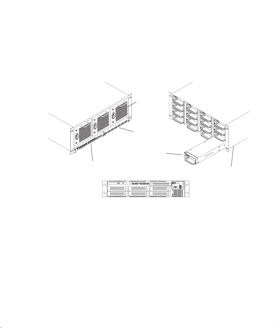
Basic Avid Unity ISIS Media Network Hardware
Rear view
Power supply
ISIS Integrated Expansion Switch (IXS)
ISIS Storage Blade (ISB)
ISIS Integrated Switch (ISS)
System Director front view
Front view
Engine
The following sections explain these components and some basic client configurations:
• System Director
• Second System Director
• Engine
• Client
• Maximum Configurations
• Basic Media Network Zone Configurations
• Supported Cabling
19
Page 20
Chapter 1 Avid Unity ISIS System Overview
System Director
The System Director is 2U in size (see “System Director Front View” on page 20) and
manages the metadata by storing directory information and file attributes. The System
Director does not store actual data, that is stored on the ISBs within the engine.
n
n
The System Director password is preset to is-admin.
You can have two System Directors configured in a redundant configuration, one Active the
other Standby. If the Active System Director goes down, the Standby System Director takes
over. You need at least one System Director to run the Avid Unity ISIS system.
n
System Directors and clients must be Time-of-day Synchronized with Clients and Servers.
The System Director provides a location to coordinate file access modes (read/write), file
locking, range locking, performance data collection, logging, file lookup, and directory
change tracking for client systems. Examples of what the System Director is able to provide
to a client or storage element are:
• Identity of all storage elements connected to the system
• Information about the ISS and IXS modules in the configuration.
• List of workspaces to include name and their unique ID number
• List of users and groups within the system
• Identity of all System Directors in the system (if you have more than one System
Director)
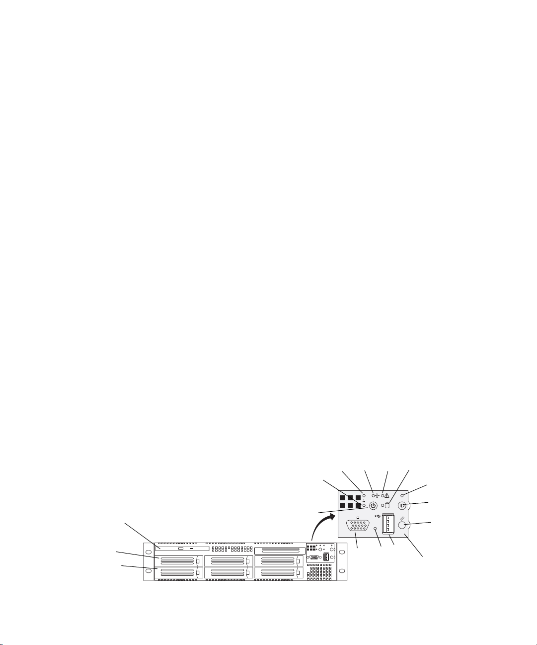
The System Director Front Panel
The following figure shows the front view and control panel of the System Director.
RAID disk (ID 1)
System disk (ID 0)
20
System Director Front View
DVD/CD-ROM
DEF
C
B
A
K
L
J
G
H
I
Control panel
Page 21
The following table describes the control panel shown in the previous figure.
l
System Director Control Panel
Letter Description Letter Description
A Power/Sleep button G System ID LED (blue, a second system
B NIC 2 activity LED H System ID button (System ID LED
C NIC 1 activity LED I System reset button
D Power/Sleep LED J USB 2.0 connector
E System status LED K Recessed NMI button (need tool)
F Internal drive activity LED L Video connector
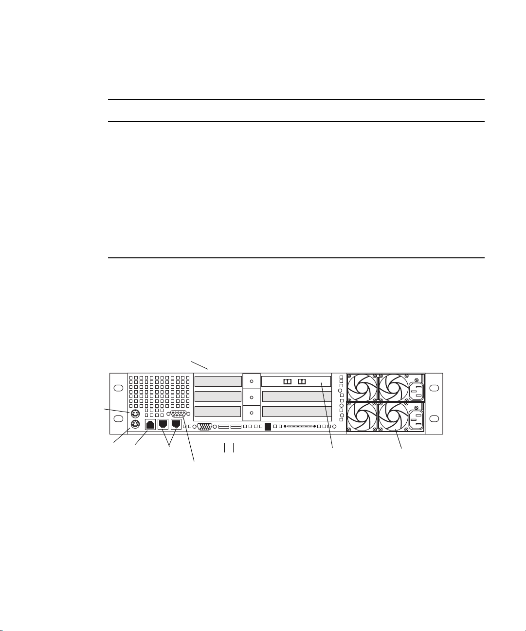
System Director Rear Connections
The following figure shows the rear panel of the System Director and the function of each
connection.
Hardware Overview
ID LED is on the rear)
blinks when pressed)
System Director Rear View
Small form factor slots not used
Mouse
Keyboard
RJ 45 to
serial B
1 Gig
Enet
Video
Serial A to F/C switch if needed
Second System Director
You can purchase a second System Director and configure it on the same subnets as the
original System Director. This provides a redundant System Director that is in constant
contact with the original System Director. The second System Director automatically takes
over if the original System Director fails (called failover).
1
USB
PCI slots Power supplies
2
SCSI B
Dual NIC Ethernet
adapter board
Primary power
supply on bottom
21
Page 22
Chapter 1 Avid Unity ISIS System Overview
n
For true redundancy it is recommended that you connect the second System Director to a
different engine than the first System Director.
Engine
The major function of the engine, with all internal components installed, is to store the data
created during actions performed by clients that are sent through the switches.
The engine contains:
• ISBs can support either 250 GB drives or 500 GB drives providing up to
192 terabytes (TB) of storage, or 96 TB of mirrored storage. As technology advances,
the storage capacity of the drives could increase, allowing the total storage per
ISB/engine to increase.
• An ISS that allow connections for clients, a 10-Gb uplink port, an engine interconnect,
and a management port for configuration. See “Integrated Ethernet Switches” on
page 24.
• An IXS used when you have more than two engines (need an IXS for each subnet),
allowing you to connect multiple engines. See “Integrated Ethernet Switches” on
page 24.
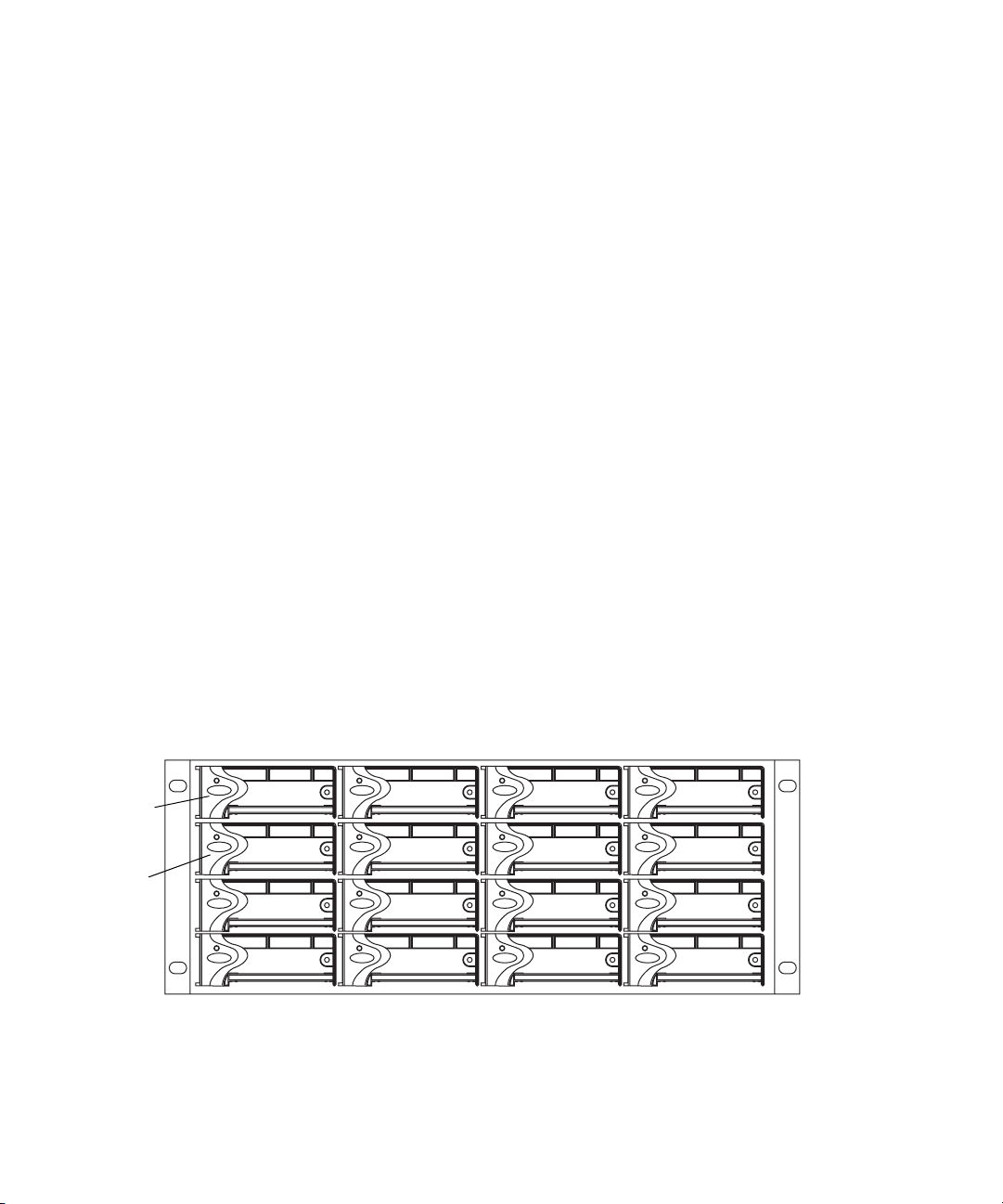
Engine Front View
The front of the engine contains the 16 ISBs. The first is in the upper left portion of the front
and the last ISB is in the lower right.
First ISB
Fifth ISB
22
Engine Front View
Each ISB can be removed and replaced separately with the power on. If you replace an ISB
with power on, the LEDs in all of the ISBs go off momentarily. This does not represent a
problem. All functions are still active and working properly.
Page 23
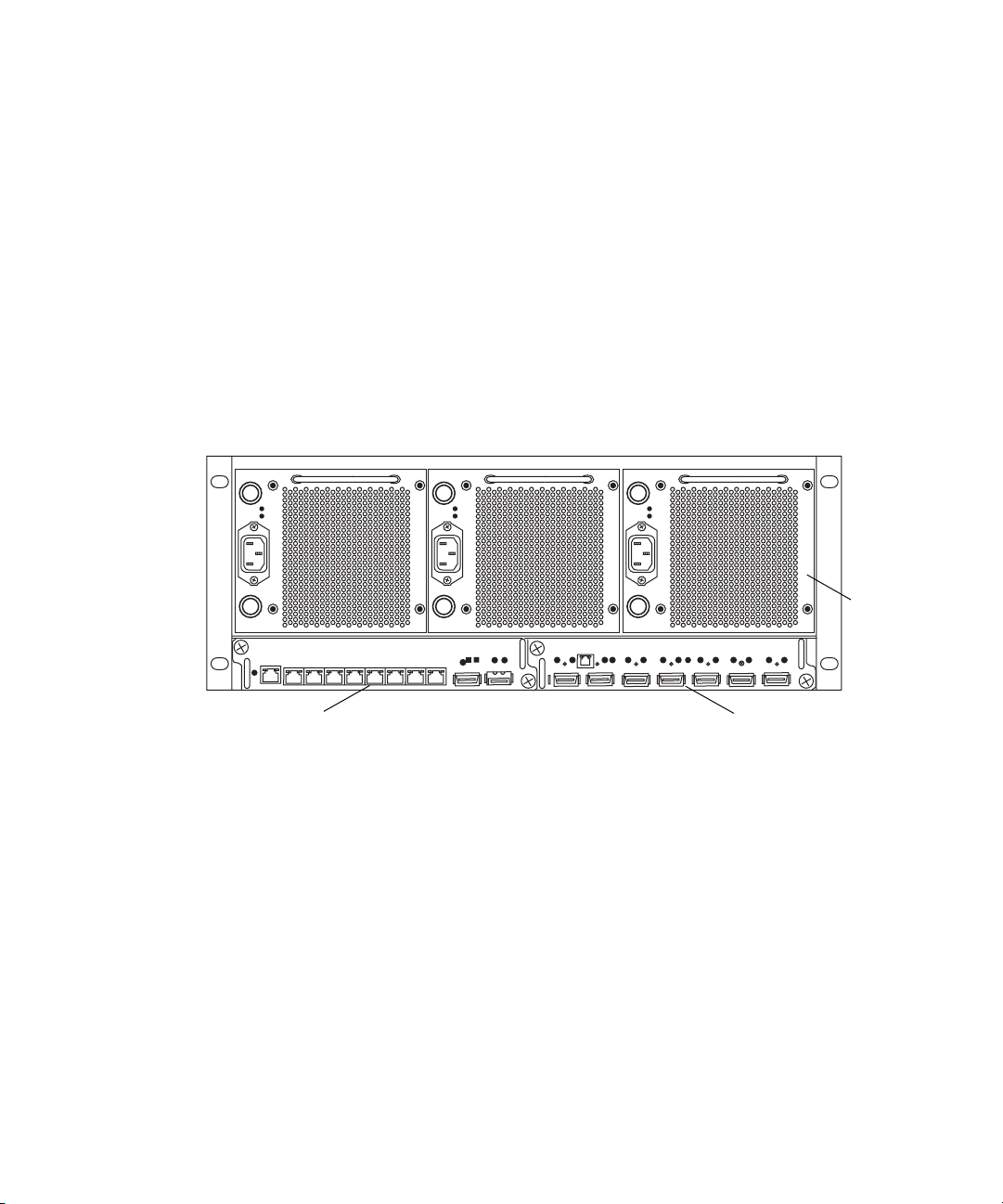
Engine Rear View
The following figure shows the rear of the engine in a configuration that contains the
following:
• Three power supplies (with fans)
• Integrated Switch blade (ISS)
• Integrated Expansion Switch blade (IXS)
Hardware Overview
n
Power Supplies
In a basic configuration containing two engines, each of the engines contains two ISS
modules. The IXS module is used with an ISS module in an engine only when the
configuration goes beyond two engines.
Engine Rear View
The power supplies are powered on when the power cord is plugged in; they do not have
power switches. The power supplies not only provide power, but they also contain fans that
cool the system. The system only needs two of three power supplies to supply the needed
power to function properly. You can remove and replace a power supply temporarily while
the system is running if one fails.
Powe r
supplies
21345678
IXS moduleISS module
c
w
You should leave the failing power supply in place until you replace the failing power
supply. Replace the power supply as soon as possible to maintain the proper airflow. Do
not remove the failing supply until immediately before you replace it.
Only trained Avid technicians should remove and replace the power supply while the
system is running. Since power to the system is still applied internally to the midplane
you must always keep your hands external to the engine when a power supply is
missing from the engine.
23
Page 24
Chapter 1 Avid Unity ISIS System Overview
Integrated Ethernet Switches
The two integrated Ethernet switches, ISS and IXS, serve different purposes and contain
different types of connections. You must have at least two switches in each engine for the
system to operate.
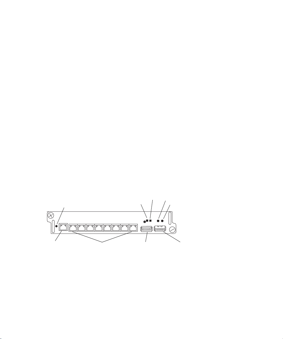
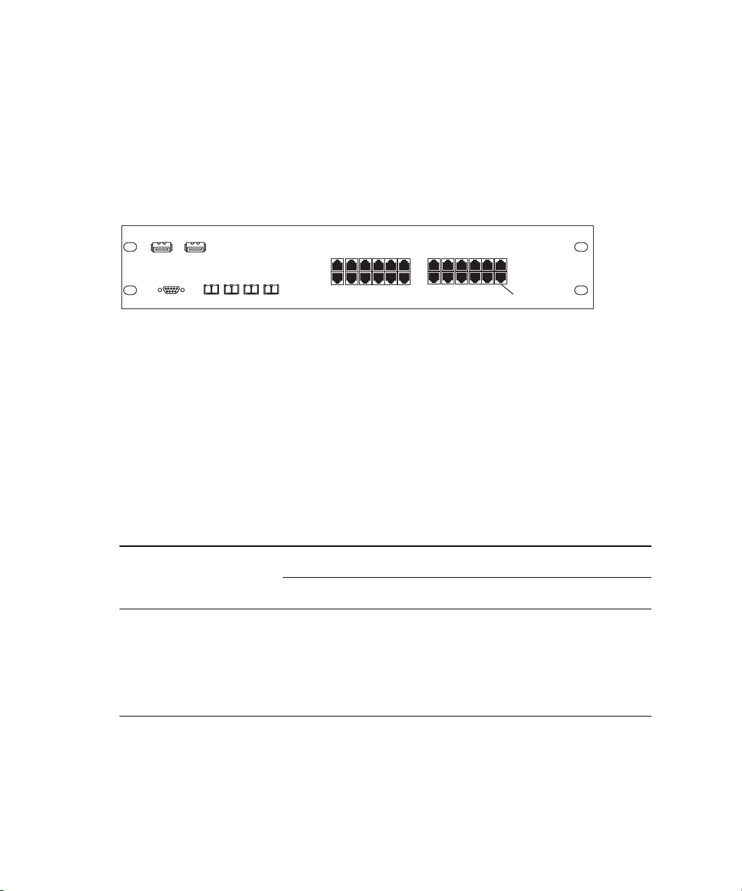
ISS Module
The connections on the ISS module are used for the following:
• Management connection — used to configure the Avid Unity ISIS engine hardware
during installation. This information is used by Avid representatives to originally
configure your system before turning it over to you.
• 1-Gb (RJ-45 cable) — direct connect for clients and the System Directors.
• High speed engine interconnect (CX-4 cable) — proprietary Avid bus that connects
switch blades between engines allowing subnets to connect between the engines.
• 10-Gb XFP MSA form factor transceiver (for Optical cable) — used to connect a 10-Gb
connection on a switch for connecting more clients.
w
Management
connection
Only an Avid recommended XFP transceiver should be used in the 10-Gb XFP
connection, and only Avid trained representatives should remove and replace the XFP
transceiver. Currently supported XFP are the Picolight XFP and Foundry XFP.
ISS Connections
Status
Activity
21345678
1-Gb connections
High speed engine
interconnect
Link
Activity
Link
10-Gb connection
IXS Module
The IXS is needed only if you are connecting three or more engines. It is used in the engine
with an ISS module. The connections on the IXS module are used for the following:
• Management connection — used to configure the switch during installation and monitor
switch functions.
24
Page 25

Hardware Overview
• High speed engine interconnect — proprietary Avid interconnection that stacks the
switches to create one large virtual switch.
IXS Connections
LinkActivityManagement
connection
Engine interconnections
n
In a basic configuration containing two engines, each of the engines contains two ISS
modules. The IXS module is used with an ISS module in an engine only when the
configuration goes beyond two engines.
Client
A client uses services provided by the Avid Unity ISIS architecture. The client system, using
a 1 Gb Ethernet connection, communicates with the ISBs through the ISS to create, modify,
and read files stored in the actual ISB.
n
MediaManager clients are the only clients that have been tested with two network
connections, one to each subnet.
A client uses mechanisms specific to a Windows operating system to display, create, and
delete files within the Avid Unity ISIS media network system. For example, when viewed
from a Windows operating system, the system sees a server containing many shares that are
mapped to drive letters.
Maximum Configurations
The maximum number of clients and the maximum amount of storage available at this time
are as follows:
• Avid Unity ISIS supports up to 300 clients (150 active clients), each using dual-stream
video and up to 8 tracks of audio.
• A fully populated Avid Unity ISIS system provides up to 192 terabytes (TB) of storage,
or 96 TB of mirrored storage connected to two subnets. A maximum of 12 Avid ISIS
Engines can use either 250 GB drives or 500 GB drives.
25
Page 26
Chapter 1 Avid Unity ISIS System Overview
n
A System Director must be attached to both subnets, but can only be attached once to each
subnet.
Basic Media Network Zone Configurations
The following four examples show different types of Avid Unity ISIS configurations.
Zone 1 Clients (Direct Connected)
Any client that is connected directly to an ISIS is considered a Zone 1 or direct connected
client. Each Integrated Switch Blade has a total of 8, 1Gb Ethernet ports. A single engine has
the capacity to support 16 clients or servers, subtracting any ports that are to be used by the
System Director(s). The following table defines the total number of Zone 1 ports based on
what is available by the number of engines and System Directors in the configuration.
n
Connect TransferManagers and playout AirSpeed servers to Zone 1 in Avid Unity ISIS v1.1.
You can connect the AirSpeed to Zone 2 if you are using the AirSpeed to capture.
A Zone 1 (direct connect) configuration consists group of clients connected directly to the
1-Gb connections of the ISS in the engine. The System Director also connects to the both
subnets via both ISS modules using a 1-Gb port.
Avid Unity ISIS Zone 1 Network Configuration
26
Client
System Director
Available Zone 1 Ports
Number of ISIS Engines One System Director
11412
23028
Client Client Client
ISS
Engine
Available Zone 1 Ports
Client
1-Gb Ethernet
ISS
Two System Directors
(failover)
Page 27
Hardware Overview
Available Zone 1 Ports (Continued)
Available Zone 1 Ports
Two System Directors
Number of ISIS Engines One System Director
(failover)
330a28
44644
56260
67876
79492
8 110 108
a. This is due to the use of an IXS board instead of an ISS.
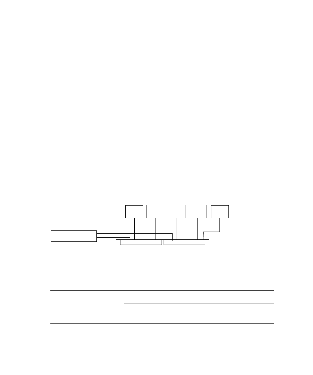
Zone 2 Clients (Indirect Connect) Configuration
There is support for external switches connected through the 10-Gb port on each ISS.
Clients that are connected to an external switch are referred to as Zone 2 clients. For a list of
supported switches, search the online Knowledge Base at www.avid.com/onlinesupport.
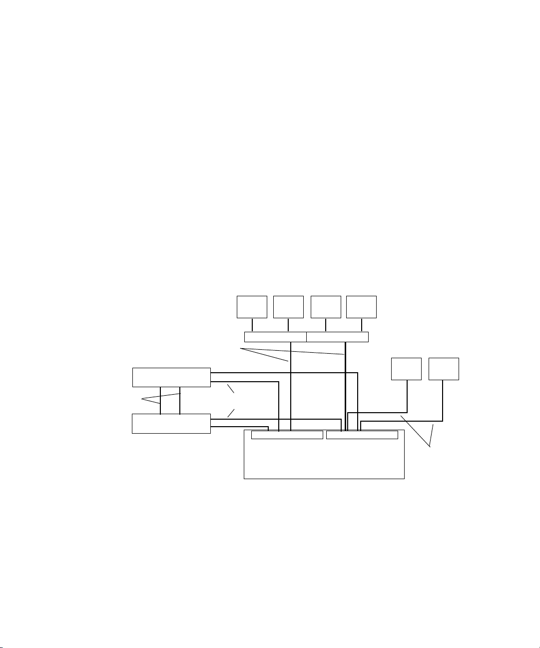
A Zone 2 (indirect connect) configuration consists of group of clients connected to an
Ethernet switch with a 10-Gb port connected to an ISS located in the engine. The System
Director also connects to the both subnets via both ISS modules using a 1-Gb port.
Depending upon the switch configuration, each client shown connected to the external
switch is connected to one of the two subnets through one of the two 10-Gb connection.
a
Avid Unity ISIS Zone 2 Network Configuration
Client
Two 10-Gb Ports
System Director
Client Client Client
VLAN 2 VLAN 1
ISS
Engine
Client
Switch with two 10-Gb Ports
ISS
27
Page 28
Chapter 1 Avid Unity ISIS System Overview
As an example, the Foundry FES-X424 switch (see following illustration) is configured for
three VLANs with Gigabit (Gb) Ethernet ports 1 to 12 and 10-Gb Ethernet port 25 reserved
for VLAN 10 (default ISIS VLAN configuration). Gigabit Ethernet ports 13 to 23 and 10-Gb
port 26 are reserved for VLAN 20 (default ISIS VLAN configuration) and Gb port 24 is
reserved for the switches default VLAN. The default VLAN port is to provide uplink
capability for clients on either VLAN. Each VLAN on the Foundry FES-X424 switch is
connected to the appropriate VLAN in the media network using the 10-Gb port.
10-Gb ports
Por ts 1 - 12 Por ts 13 - 24
Por t 2 5 Por t 2 6
1-Gb ports
Por t 2 4
Each VLAN on the switch is allowed to support up to 12 connections but the size of the
Storage Groups and engine determine the overall client count. Changing the switch
configuration to increase the number of clients on a single VLAN is not supported and can
result in unpredictable system performance. Client count can be scaled according to the
number of available FES-X424 switches.
The following table provides possibilities of Zone 2 client counts based on the number of
ISIS engine and Foundry FES-X424 switches. For each engine listed in the table, there is an
associated Foundry FES-X424. The exception is with three engines, in which the IXS does
not provide additional ports.
Available Zone 2 Ports
Available Zone 2 Ports
Number of Engines FES-X424 Switch Count External Switch Ports
11 23
n
28
22 46
32 46
43 69
a. This is due to the use of an IXS board instead of an ISS.
a
The above table does not reflect the use of Zone 1 Clients (Direct Connect), which at a
minimum could consist of one System Director, AirSpeed devices, and TransferManagers.
Mixing Zone 1 and Zone 2 clients in an ISIS media network is discussed in the next section.
Page 29
Hardware Overview
n
There is no current support for an external switch to be connected with the use of a 1Gb
connection as performance for multiple clients cannot be guaranteed over a single 1Gb
connection.
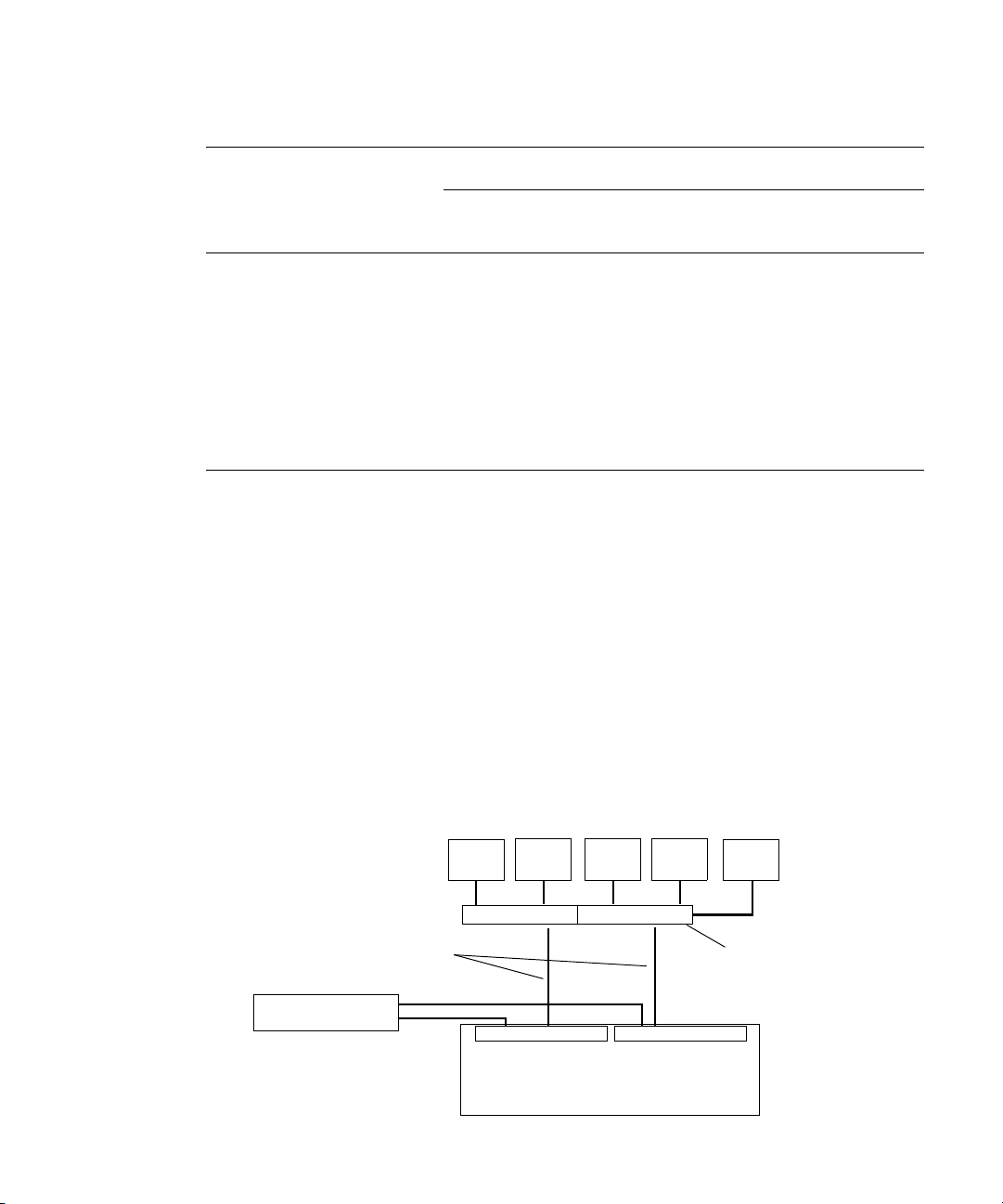
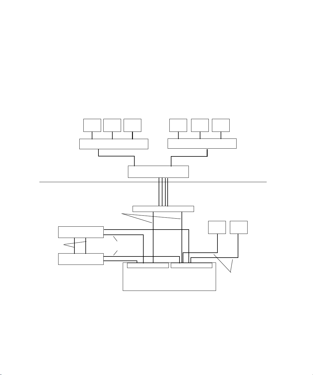
Zone 1 and Zone 2 Clients Mixed Configuration
The more common network configuration that is to be used in the event of Gigabit Ethernet
port limits of the ISIS Integrated Switch Blade is to combine both Zone 1 and 2 clients in the
same ISIS media network.
A mixed configuration (Zone 1 and Zone 2) of clients consists of group of clients
connected directly and indirectly to an engine through a switch blade. Also shown are two
System Directors that connect to the engine via two separate ISS 1-Gb ports for use as a
redundant System Director in case of a failure. Both System Directors also connect to each
other through the onboard Ethernet connections to monitor if one of the System Director
fails.
Avid Unity ISIS Zone 1 and Zone 2 Mixed Network Configuration
Client
10-Gb Ports
Client Client Client
VLAN 20 VLAN 10
1-Gb Ethernet
Switch with two 10-Gb Ports
n
Client Client
1-Gb Ethernet
Failover
connection
System Director
System Director
1-Gb Ethernet
ISS
ISS
Engine
Although it is not show in the above diagram, to ensure high availability, whenever possible,
the System Directors should be connected to two different subnets through two different
engines.
29
Page 30
Chapter 1 Avid Unity ISIS System Overview
Zone 3 Client Configuration
A Zone 3 (indirect connect) configuration consists of group of clients normally connected to
an Edge access Ethernet switch.
This switch is normally connected to a core switch that has uplinks that connect to the Avid
Network through an Ethernet switch that contains a 10-Gb port connected to an ISS located
in the engine. The System Director also connects to the both subnets via both ISS modules
using a 1-Gb port.
Avid Unity ISIS Zone 3 Network Configuration
Corporate network
Avid network
System Director
Failover
connection
System Director
Client
10-Gb Ports
Client Client Client Client Client
Edge switch
Core switch
VLAN 10 VLAN 20
1-Gb Ethernet
ISS
Engine
Edge switch
One to four, 1-Gb Ethernet links
Switch with two 10-Gb Ports
ISS
Client Client
1-Gb Ethernet
Supported Cabling
Avid supports the following cable types for connecting a Avid ISIS system.
n
30
If you need run your cable distances, call Avid Customer Support for supported cable and
accessory information.
Page 31

Supported Cables
Cable Name Function Maximum Distance
Hardware Overview
Avid engine Interconnect
CX-4 cable. Only
available from Avid.
RJ45 Cat 5E or Cat 6
Ethernet cable (minimum).
Cat5 cable is not supported
for these connections.
Optical (XFP) cable.
Read the Caution below
this table when using an
Optical XFP cable.
Connect engines. See Avid
Engine CX-4 Interconnect Cable
for proper removal.
Connect management port to
laptop,
Connect System Director to an
ISS, connect two System
Directors Ethernet boards,
connect client to 1 Gb ports on
an ISS.
Connect 10-Gb port of switch to
XFP optical 10-Gb port on the
engine.
3 supported lengths at this time:
1, 3 and 5 meters
100 Meters; If using CAT5E the cable must be
rated for 350 MHz for maximum length.
The maximum length of the cable is defined by
the micron and modal bandwidth.
Avid supports two lengths of the 850 nm cable for
short distances:
• MMF 62.5 micron cable Modal = 200 at 33
meters
• MMF 50 micron cable Modal = 2000 at 300
meters
Avid supports the 1310 nm cable for long
distances:
• SMF ITU G.652.A/B 9 micron cable up to 10
km
Transceivers, X2 and XFPs
Cisco 4948 uses X2s, not XFPs
Foundry FESX 424 XFP
ISIS ISS XFPs
X2 and XFP names
•SC to SC
X2 = Cisco X2-10GB-SR for MMF
X2 = Cisco X2-10GB-LR for SMF
•LC to LC
XFP = 10G-XFP-SR for MMF
XFP = 10G-XFP-LR for SMF
XFP = Foundry 10G-XFP-SR
or Pico-light XXL-SC-S45-21 for MMF
XFP = Foundry 10G-XFP-LR
or Bookham 10G-BASE-LR for SMF
31
Page 32

Chapter 1 Avid Unity ISIS System Overview
w
The Optical (XFP) cable is an international Class 1 laser product per IEC 60825-1
Amendment 2(2001) and IEC 60825-2 1997. Operating this product in a manner
inconsistent with intended usage and specification may result in hazardous radiation
exposure. Tampering with this laser based product or operating this product outside
the limits of this specification may be considered an act of “manufacturing,” and will
require, under law, recertification of the modified product with the U.S. Food and Drug
Administration (21 CFR 1040). Published by Picolight Incorporated. All rights
reserved.
Connecting the Engine CX-4 Cable
To connect the cable:
t Place it in the connector at the rear of the system.
You hear a snap, and the cable is connected.
Avid Engine CX-4 Interconnect Cable
Cable disconnect
c
n
Damage can occur when disconnecting the Avid engine Interconnect cable from the
switch board if not done properly.
Care should be taken to reduce strain on the ISS switch blades by organizing and dressing
the ethernet cables and CX-4 cables. When dressing the cables do not block removable
switch and power components.
Removing the Avid Engine Interconnect Cable
c
32
If you attempt disconnect the cable by pulling the blue cable release towards you and
pulling the cable out from the connector at the same time you can cause the cable and
or connector to be damaged. The following explanation and illustration explain how to
properly remove the engine interconnect cable.
Page 33

To remove the Avid Engine Interconnect Cable from the Rear Connector:
1. While the cable is in the connector, use your bottom hand to grab the cable (or the metal
portion of the connector) and push the cable (or metal portion of the cable) towards the
connector at the rear of the engine.
2. While keeping the pressure towards the engine connector using the cable (or the metal
portion of the connector), use the top hand to pull the blue portion of the cable directly
back. This dislodges the connection of the cable from the connector.
Bottom hand
pushing cable
Pull back on blue
cable release
Push cable or metal
towards engine
3. Pull back with both hands to remove the cable.
10-Gb Link Aggregation Overview
10-Gb Link Aggregation Overview
This chapter provides an overview of 10-Gb Link Aggregation functionality, supported by
Avid Unity ISIS software. The following sections describe 10-Gb Link Aggregation, for a
procedure on creating a link aggregation Group, see “Configuring a 10-Gb Link
Aggregation” on page 99. When configuring a Hi-Gb link aggregation for ten- and
twelve-engines, see “Hi-Gig Link Aggregation” on page 62.
Link aggregation is a method of combining physical network links into a single logical link
for increased bandwidth. With Link aggregation, your are able to increase the capacity and
availability of the communication channel between devices (both switches and clients) using
existing Ethernet technologies. Two or more 10-Gb Ethernet connections can be combined
to increase the bandwidth capability and to create resilient and redundant links. Link
aggregation sometimes known as “Trunking.”
Link aggregation also provides load balancing across several links in a link aggregation so
that no single link is overwhelmed.
n
You must disable link aggregation before creating or modifying your Avid Unity ISIS stack.
After your stack has been created, reconfigure your link aggregation.
33
Page 34

Chapter 1 Avid Unity ISIS System Overview
Supported in Link Aggregation
Avid Unity ISIS supports 10-Gb link aggregation (between the ISS and the Avid Production
Network switch) and Hi-Gig link aggregation (between two IXS). Avid Unity ISIS software
supports the link aggregation standard 802.3ad.
Number of Groups Supported
A link aggregation group refers to a number of links that combine together to form a single
link aggregation. The number of link aggregation groups supported in Avid Unity ISIS is
five.
Number of Members Supported
A link aggregation group can have a maximum of eight members. This means no more than
eight 10-Gb links can be combined into one link aggregation group per VLAN. The
minimum number of link aggregation members in a group is 2.
For performance reasons, Avid recommends that you maintain an even number of link
aggregation members. So for an eight engine stack, you can have a link aggregation group
with two, four, and six members. For a ten or twelve engine stack, there can be two, four, six,
and eight members in a link aggregation group.
n
If a member is already part of a link aggregation group, it cannot be part of another link
aggregation group. You also cannot create a link aggregation group with a single member.
Load Balancing
The software balances the load across multiple 10-Gb aggregated links based source and
destination IP addresses.
Failover
If a 10-Gb link fails, the software does not load balance traffic to the remaining links.
Warning messages are sent to Administration tool notifying you that a 10-Gb aggregation
link status has changed.
The engine menu within the Administration tool flashes a yellow warning triangle notifying
you that a 10-Gb Link Aggregation link has changed. The specific engine displays a yellow
warning circle, and the Switch Blade Status displays “1 Error(s).” Details on the engine
switch displays a status of “Link Warning.” You can then open the Switch Agent page via the
“info” button on the engines details page, and look at the Port Status page to verify the
10-Gb Link Status.
34
Page 35

10-Gb Link Aggregation Overview
n
For Hi-Gb link aggregation, the software supports dynamic traffic failover across Hi-Gb
links.
Recommended Topologies
For the best performance in stacks with two IXSs, the link aggregation members need to be
evenly distributed between the ISSs that are connected to each IXS. For example, with a four
link group; two are connected to ISSs that are connected to IXS A, and the other two links
are connected to ISSs that are connected to IXS B.
Supported Functionality
From the Link Aggregation menu in the switch agent, you can:
• View current settings — This displays the current link aggregation configurations,
showing all currently configured groups. The user may also modify a group or delete a
group from this page.
• Create a new link aggregation group — This allows you to define a new link aggregation
group.
• Enable or disable link aggregation configuration — This allows you to disable or enable
the current link aggregation configuration. The configuration is preserved.
• Restart the link aggregation configuration — This allows you to request that the stack
restart its link aggregation configuration. This removes and rebuilds the link aggregation
groups as defined in the current configuration.
• Delete the link aggregation configuration — This disables link aggregation and removes
any existing link aggregation configuration. The configuration is not recoverable. This
can be used to set link aggregation settings back to factory defaults.
Other Functionality
• Every time a switch is introduced to the stack (by connecting the stacking cable) or
removed from the stack (by disconnecting the stacking cable), the link aggregation
software clears the link aggregation information from the switches and re-programs
them again.
• If the switches are being programmed with link aggregation information for the first
time, link aggregation needs to be enabled. This is done by clicking on “Enable or
Disable link aggregation configuration.”
Client Types
A link aggregation configuration supports both Zone 2 and Zone 3 clients.
35
Page 36

Chapter 1 Avid Unity ISIS System Overview
36
Page 37

Chapter 2
Connecting the Equipment
This chapter explains how to rackmount and connect the system hardware. To do this, a
system installation check list is provided to help you perform the installation in the correct
order. The installation check list continues past the information in this chapter and points
you to the correct area in this document or the ReadMe file to continue the installation.
c
n
Prior to installing and connecting the equipment in racks, you must use the
Avid Unity ISIS Site Preparation Guide for explanation of power and other installation
needs.
This chapter contains the following information:
• Rack-Mounting the Equipment
• Installing Blades and Power Supplies
• Connecting Power to Equipment
• Connecting the Application Key
• Connecting the Engine
For information on connecting and configuring two System Directors for failover, see
“Configuring the System for Failover and 10-Gb Link Aggregation” on page 85
Page 38

Chapter 2 Connecting the Equipment
Rack-Mounting the Equipment
This chapter describes how to install and connect the System Director and other workgroup
hardware.
c
c
Information concerning power, airflow, and dimensions are explained completely in the
Avid Unity ISIS Site Preparation Guide located on the documentation DVD. You should
understand the basic power configurations explained in “Connecting Power to
Equipment” on page 45.
Before you start the procedures in this chapter, you should be familiar the previous
chapters in this document.
Rack-Mounting Examples
Avid supports more than one Avid Unity ISIS rack configuration. You should have discussed
the layout for your system with an Avid representative prior to purchase.
The following examples show a few of the supported rack configurations.
Single Rack - Two Engines - One System Director
System
Director
38
Engines
Page 39

IXS
Rack-Mounting the Equipment
Single Rack - Four Engines - One System Director
Switch
A B
System
Director
MGMT
STATUS
MGMT
STATUS
S
MGMT
STATU
21345678
21345678
21345678
MGMT
STATUS
TUS
MGMT
STA
MGMT
STATUS
21345678
Engines
21345678
21345678
39
Page 40

Chapter 2 Connecting the Equipment
Dual Rack - Four Engines - Failover System
MGMT
STATUS
21345678
Rack 1
MGMT
STATUS
21 345678
Switch
S
21345678
MGMT
STATU
21345678
MGMT
STATUS
Installing Rack-Mount Rails and Brackets
Rack 2
TUS
MGMT
STA
MGMT
STATUS
21345678
21345678
System
Directors
Engines
n
40
All Avid Unity ISIS rack-mount components are supplied with either mounting rails or
brackets. You should follow the manufacturer’s installation instructions supplied with each
component to correctly attach the rails or brackets to the rack rails.
Where necessary, this guide supplies specific rack-mount rail or bracket installation
instructions. These instructions supersede the manufacturer’s instructions.
Page 41

Installing System Director and an Avid ISIS Engine
The System Director and storage elements are placed into a rack for easy access to the
cables, connectors, and drives. The following list provides recommendations you should
take into account prior to rack-mounting Avid Unity ISIS equipment:
• The heaviest equipment should go at the bottom of the rack, for example, the
Avid Unity ISIS engine.
• Lighter equipment goes towards the middle and top of the rack, for example, System
Directors, a Keyboard, monitor, and mouse assembly (KMM), with Ethernet switches at
the top of the rack.
• If the rack is provided with stabilizing devices, install the stabilizers before mounting
the equipment in the rack.
• Avid recommends that you leave a 1U or .5U space between each piece of equipment
mounted in the racks. This allows for better airflow and cable access, and helps stop
vibration in any equipment being transferred to spaces above and below.
• Avid recommends that you leave an 8 to 12 inch space at the bottom of the rack. This
allows for better airflow and lowers the possibility of dust or dirt being picked up by the
devices.
• If you have a redundant configuration, you might place equipment in different racks.
Place the System Director and Failover System Director in different racks, separate the
storage elements between racks, place redundant Ethernet switches in different racks,
and have the power from each rack connected to different circuits.
Rack-Mounting the Equipment
• For normal operation, you’ll need to maintain approximately 2 feet (0.6 meters) of open
space in front of and behind the rack. This allows free access to the components in the
rack for operating changes or adjustments. For service, you need approximately 3 feet
(1 meter) of open space in front of the rack and 2 feet (0.6 meters) of open space behind
the rack. This allows for the removal of any component that needs to be replaced.
n
For more information related to rack mounting a Avid Unity ISIS system, see the
Avid Unity ISIS Site Preparation Guide online on the Avid Knowledge Base or the online file
on your Avid Unity ISIS system DVD.
Mounting the Engine
w
Lifting the engine with the blades and power supplies installed can cause an injury.
The engine must have the blades and power supplies removed prior to lifting. Avid
recommends that two persons should be used whenever lifting the empty engine.
41
Page 42

Chapter 2 Connecting the Equipment
To mount the engine into the rack:
1. Screw the brackets to the rear of the rack as shown in the following figure.
Connecting Rear Brackets
Rear
2. Make sure that the blades and power supplies are not in the engine.
3. Using two people, lift the engine and place the rear of the engine onto the brackets as
shown in the following figure.
42
Mounting the Engine
4. Screw the engine to the front of the rack through the ears of the engine as shown in the
preceding figure.
Page 43

Installing Blades and Power Supplies
Installing Blades and Power Supplies
Once the engine has been mounted follow the instructions listed below.
To place the power supplies and blades into the engine:
1. Unpack each ISB and turn it so you can properly read the Avid name.
2. Place the ISB into the slot and slowly push the ISB into the slot until you hear a click.
3. Repeat step 1 and step 2 until all blades are installed.
4. Carefully unpack each power supply.
w
Avid recommends that two persons be used to install the power supplies. You could be
injured if you dropped a power supply on any part of your body.
5. Place the power supply into the engine as shown in the following figure and slowly push
the power supply into the slot.
Screws
6. Turn the screws until tight.
7. Repeat from step 4 until all power supplies are installed.
43
Page 44

Chapter 2 Connecting the Equipment
w
Only trained Avid technicians should remove and replace the power supply when
power is applied to the system. Since power to the system is still on, you must always
keep your hands external to the engine when a power supply is missing from the
engine.
Installing IXS and ISS Switches
The location of the ISS and IXS switches in the stack are very important. If you have only
one or two engines you should only be installing ISS switches into the engines, see “Two-
Engine Connections” on page 52.
If you have more than two engines you need two IXSs. IXSs are installed in pairs in the
same engines. The engines with the IXSs should always be in the first and second engines at
the top of the stack, see “Three- to Eight-Engine Connections” on page 52. You need four
IXSs in ten- and twelve-engine configurations, see “Ten- and Twelve-Engine Connections”
on page 54.
To install your IXS or ISS:
1. Unpack the switch and insert the switch edges into the internal engine slides.
2. Carefully push the switch into the midplane of the engine until the connection is made.
3. Tighten the thumbscrew on each side of the switch.
Installing Switches into an Engine
44
IXS
Thumbscrews
Page 45

Connecting Power to Equipment
The Avid Unity ISIS hardware includes three power supplies using an N+1 configuration for
redundancy. The three power supplies “load share” to allow the balanced distribution of ac
power into each Avid Unity ISIS engine. Usually, a minimum of two of the three power
supplies must be operational at one time for the engine to function properly. Each power
supply contains fans and provides a physical function having to do with airflow for the
engine. If a power supply fails, leave it in place until you have a replacement.
Avid recommends that each power supply be provisioned with at least 5 amps of current
capacity per power cord (120 Vac). This allows the system to continue running if one of the
three power supplies fails, with the two remaining load-sharing power supplies drawing
slightly less than 10 amps.
Connecting Power to Equipment
n
c
Do not actually connect the power cords to the engines until told to do so in “Configuring
the Engine” on page 76.
Use this section to determine how you should connect power to the engines. Place the
power cords into the engines when you place them into the rack as explained in “Rack-
Mounting the Equipment” on page 38, but do not plug them into the outlets until told
to do so later in the document.
See the following sections:
• Three 20-Amp AC Circuits for Three Engines
• Three 20-Amp AC Circuits for Two Engines
• Two 20-Amp AC Circuits for Two Engines
45
Page 46

Chapter 2 Connecting the Equipment
Three 20-Amp AC Circuits for Three Engines
When you are using three 20-amp circuits for three engines, they are configured as follows:
• Each Avid ISIS engine — Each engine has three power supplies; Each power supply is
rated at 5 amps input at 120 Vac. You can have up to one power supply from each of the
three engines on one 20-amp circuit.
n
Each System Director has up to two power supplies rated at 5.8 amps each. Each System
Director includes two power supply. Use one 20-amp circuit for each System Director.
An engine can operate on two power supplies for a period of time to allow you to protect
data. The following illustration shows an example of how the power should be connected to
protect data.
Basic Power Connection for Three ISIS Engines
Slot 3
System Director
System Director
Slot 2
Slot 1
Slot 3
Slot 2
Slot 1
BCA
Engine
BCA
Engine
20 Amp
20 Amp
46
BCA
Engine
20 Amp20 Amp
20 Amp
Page 47

Three 20-Amp AC Circuits for Two Engines
When using three 20-amp circuits for the engine, they are configured as follows:
• Each Avid ISIS engine — Each engine has three power supplies; Each power supply is
rated at 5 amps input at 120 Vac. You can have up to three power supplies from two
different engines on one 20-amp circuit.
Connecting Power to Equipment
n
Each System Director has up to two power supplies rated at 5.8 amps each. Each System
Director includes two power supplies. Use one 20-amp circuit for each System Director.
An engine can operate on two power supplies for a period of time to allow you to protect
data. The following illustration shows an example of how the power should be connected to
protect data.
First Example of Power Connection for Two ISIS Engines
Slot 3
System Director
System Director
20 Amp 20 Amp 20 Amp
Slot 2
Slot 1
Slot 3
Slot 2
Slot 1
BCA
Engine
BCA
Engine
20 Amp
20 Amp
n
The 20-amp circuits shown for the System Directors should remain the same for both the
three and two 20-amp circuit examples.
47
Page 48

Chapter 2 Connecting the Equipment
Two 20-Amp AC Circuits for Two Engines
c
n
The following configuration is not recommended by Avid, but some locations might
need to connect in this manner.
When using two 20-amp circuits for the engine, they are configured as follows:
• Each Avid ISIS engine — Each engine has three power supplies; Each power supply is
rated at 5 amps input at 120 Vac. You can have up to three power supplies from two
different engines on one 20-amp circuit.c
Each System Director has up to two power supplies rated at 5.8 amps each. Each System
Director includes two power supply. Use one 20-amp circuit for each System Director.
An engine can operate on two power supplies for a period of time to allow you to protect
data. The following illustration shows an example of how the power should be connected to
protect data.
Second Example of Power Connection for Two ISIS Engines
System Director
System Director
Slot 3
Slot 2
Slot 1
Slot 3
Slot 2
Slot 1
BCA
20 Amp
20 Amp
n
48
Engine
BCA
Engine
20 Amp 20 Amp
The 20-amp circuits shown for the System Directors should remain the same for both the
three and two 20-amp circuit examples.
Page 49

Turning System On and Off
To turn the system on or off, use the following procedures. Do not turn off the Avid Unity
ISIS components until they have completely powered on.
To turn your system on.
1. Turn on your engines one at a time by plugging at least two power cords into two power
supplies at the same time. Plug the third power cord into the third power supply soon
after the first two powers supplies have been given ac power. Allow enough time for all
lights on the front panel to turn Green.
2. Turn on the System Directors and to start the Avid Unity ISIS system.
3. Clients should restart there systems and use the Client Manager software to log on and
mount workspaces.
To turn your system off.
1. Exit the Client Manager on all clients.
2. Stop the secondary System Director using the System Director Control Panel if you are
set up for failover.
3. Stop the Active System Director using the System Director Control Panel.
Connecting the Application Key
4. Turn off the System Directors.
5. Turn off the engines one at a time by unplugging the three power cords for each engine.
Connecting the Application Key
Before you start the System Director, you need to connect the Avid Unity ISIS system USB
application key (also called a dongle). The USB application key determines how many Avid
Unity ISIS clients can simultaneously use your system.
c
c
Do not lose the USB application key. Your Avid Unity ISIS system does not function
without it. If you lose the USB application key, you must purchase another one from
Avid to use your Avid Unity ISIS system software.
To connect the application key to your Avid Unity ISIS system:
1. Locate the USB application key in your Avid Unity ISIS system kit.
2. Attach the USB application key to one of the rear USB ports of the System Director; see
“System Director Rear Connections” on page 21.
Do not use the built-in USB connector on the front of the SR2400 File Manager.
49
Page 50

Chapter 2 Connecting the Equipment
Connecting the Engine
The process of connecting the engines to the Avid Unity ISIS network is a two step process.
Once you logically configure the addresses for the engine, you physically make the
connection to complete the process. If you need to install software, see “Configuring Avid
Unity ISIS Hardware and Installing Software” on page 65.
c
The engines are powered on when two or three power supplies are plugged into an ac
power source. When the engines are on, and the interconnect cables are attached, the
network tries to identify the new connection before it should. Do not connect the
interconnect cables until told to do so in the procedures.
You will need the following:
• Windows computer (laptop or System Director)
• Cat5E or Cat6 Ethernet cable to run between the Windows computer and the
Management port of the IIS or IXS
• Two or more engine interconnect cables (when using more than one engine)
• System Director DVD/CD ROM
Engine Configuration Guidelines
Although there are a few ways to physically connect and enable the engines, Avid
recommends the process described in this section for consistency and dependability. In
smaller configurations different switch blades are used:
• ISS — Only the ISS blades are used when you are connecting two engines.
• IXS — When connecting three to eight engines, you must use at least two IXS blades
(one in each subnet) to connect each engine. Ten- and Twelve engine configurations
require at least four IXS blades.
n
n
50
Nine- and eleven-engine configurations are currently not supported.
Engine configurations are described in the following sections:
• Two-Engine Connections
• Three- to Eight-Engine Connections
• Ten- and Twelve-Engine Connections
• Hi-Gig Link Aggregation
You must disable link aggregation before creating or modifying your Avid Unity ISIS stack.
After your stack has been created, reconfigure your link aggregation.
Page 51

Connecting the Engine
Use the following list to help you when you connect the System Director, laptop for
configuration, and clients to the Avid Unity ISIS system.
• A laptop (or any computer running on a Windows XP operating system) is used in the
following examples for configuring the engine at the beginning of the installation or for
maintenance by an Avid representative. You can use the 1-Gb connection on the System
Director for configuring the engine at the beginning if needed, but do not leave it
connected or use it for a maintenance connection.
• All clients connected to the switches on the left side of the engine are connected to one
subnet, while clients connected to the switches on right side of the box are connected to
the second subnet.
• When you are connecting the System Director to the ISS module using the dual port
Ethernet board, Avid recommends that you connect the left port to the left side of the
engine and the right port to the right side of the engine. Where the left side corresponds
to the VLAN 10 subnet and right side corresponds to the VLAN 20 subnet. However, it
also functions properly the other way.
You should rename the left side, to “Left Side, VLAN 10” and the right side, to “Right
Side, VLAN 20” in the Network Properties of your System Director.
• When creating ten- and twelve-engine configurations, your stack must be balanced with
with the same amount of engines on each IXS in each subnet. In other words, the two
IXSs on each subnet must have the same number used.
51
Page 52

Chapter 2 Connecting the Equipment
Two-Engine Connections
The following example shows the physical connections between two engines, a System
Director, and clients. These are direct connections to the client system and not connected
through switches.
Two-Engine Connections
To client - RJ45 connector, CAT 5E or CAT 6
Inter-engine
connection - CX4 connector
Avid cable
Left side Right side
RJ 45 connector,
CAT 5E or CAT 6
S
U
T
A
T
MGMT
S
S
U
T
A
T
MGMT
S
System
Director or
laptop for
configuring
Connection 1
only
Three- to Eight-Engine Connections
The following example shows the physical connections between four engines, a System
Director, and clients. These are direct connections to the client system and not connected
through switches. Although the example shows four engines, the process is the same for
connecting up to eight engines.
21 345678
21 345678
S
U
T
A
T
MGMT
S
S
U
T
A
T
MGMT
S
21345678
21345678
ISS
52
Page 53

Connecting the Engine
n
The initial release of Avid Unity ISIS illustrated one IXS in each engine. The following figure
shows two IXSs in the same engine. You do not need to reconfigure your engines to move the
IXSs to the same engine unless you are upgrading your Avid Unity ISIS environment to a tenor twelve-engine configuration.
Three to Eight-Engine Connections
Left side Right side
Inter-engine
connection
IXS
RJ 45 connector,
CAT 5E or CAT 6
System
Director or
laptop for
configuring
only
21 345678
TUS
MGMT
STA
21345678
Management port
connection
MGMT
STATUS
S
MGMT
STATU
21345678
21 345678
TUS
MGMT
STA
TUS
MGMT
STA
21345678
21345678
ISS
53
Page 54

Chapter 2 Connecting the Equipment
Ten- and Twelve-Engine Connections
This section describes the recommended process for connecting a ten- or twelve-engine
Avid Unity ISIS. You need to connect the engines before configuring the link aggregations.
If you are upgrading from a eight or less engine configuration see, “Expanding to a Ten or
Twelve Engine Stack” on page 63.
n
Avid Unity ISIS v1.1 or later is required for ten- and twelve-engine configurations. Switches
running v1.1 software cannot stack with switches running Avid Unity ISIS v1.0 and
immediately results in stacking failures. If updating your configuration with an earlier
version of software and 8 engines, you must upgrade your software first. For information on
upgrading switches to v1.1, see the Avid Unity ISIS ReadMe.
When configuring Avid Unity ISIS for a ten- or twelve-engine configurations, connect and
add the switches to the VLAN 10 subnet (left side) first and then connect the engines to the
VLAN 20 (right side) subnet. When accessing the Agent Web pages for the engines, use
your laptop through the Management port. Although the Switch Agent Web page can be
accessed through the Avid Unity ISIS software on your System Director, that is not the
recommended process in this procedure. Information on installing the software on the
system Director is described in “Installing Avid Unity ISIS Software” on page 69.
In the following procedures, the IXS ports 1 through 7 are referred to from left to right as
shown in the following figure.
IXS Engine Port Numbering
IXS module
54
Management
connection
Port 1 Port 2 Port 3 Port 4 Port 5 Port 6 Port 7
Engine interconnections
Page 55

Connecting the Engine
In ten- and twelve-engine configurations, four IXSs are installed in the first two engines
(two IXSs in each engine). In the following procedure the four IXSs are identified as
follows:
• IXS A — The first IXS on the left side; VLAN 10 (first engine)
• IXS B — The second IXS on the left side; VLAN 10 (second engine)
• IXS C — The first IXS on the right side; VLAN 20 (engine 1 with IXS A)
• IXS D — The second IXS on the right side; VLAN 20 (engine 2 with IXS B)
Avid strongly recommends you keep your engines and IP addresses in order in conjunction
with the order of the ports used on the IXSs. When the IP address of the engines are in order
with how they are mounted in the rack, support personnel can better identify the connections
and components in the network. For an overview of the recommended IP addressing, see “IP
Addressing Overview” on page 65.
n
n
The following procedure focuses on the cabling and might not represent your actual rack
configuration.
To connect the VLAN 10 subnet (left side):
1. Loosen the thumb screws on the right side switches (ISX and ISS) and pull the right side
switches out about an inch of all the engines (so they are not electrically connected in
the engine).
2. Connect the power cords from at least two of the engine’s power supplies to ac circuit at
the same time. Then connect the third power supply.
It should take about 2 minutes for the engines to reach ready status. Wait for all the
LEDS on the engine to be green.
3. Power on all the engines in the stack.
Power cords are plugged into the engines early in the process to speed up the installation
time. Engines can take a minute or two to become ready. If the engines are ready when it is
time to add them to the stack, the installation takes less time. Do not plug the interconnect
cables into the engines until instructed to do so.
4. Using a laptop (or other Windows XP computer), assign a static IP address of
192.168.0.100 to the network adapter (NIC) and attach it to the management port of
IXS A.
5. Start your Internet Explorer browser and navigate to the Switch Agent Web page via the
URL https://192.168.0.10:5015.
6. Go to the Add/Remove Chassis tab and click Add chassis
7. Immediately attach an interconnect cable from port 6 of IXS A to port 6 of IXS B (in the
second engine).
55
Page 56

Chapter 2 Connecting the Equipment
c
c
n
You must use port 6 to connect the IXS to another IXS. Ports 1 through 5 can only be
use to connect ISSs.
8. Verify that the switch was added to the stack successfully.
The serial number of the new engine appears in the Add/Remove Chassis list after a few
moments when the switch is successfully added. If the new engine does not appear in
the list (times out), see “Engine Does Not Appear in Add Chassis List” on page 80. You
can also navigate to the Tools tab and verify that IXS A can ping the added switch via
the expected IP address.
Do not connect both ports 6 and 7 before the IXS’s are configured for link aggregation.
If two stacking cables are connected between the IXS’s without link aggregation
enabled, then traffic loops occur. For information in correcting a traffic loop, see
“Recovering from Stacking Problems” on page 105.
9. Go back to the Add/Removed Chassis pane and click Add Chassis from IXS A’s Agent
Web page using the IXS management port.
10. Connect an interconnect cable from the left side of a third engine to port 1 of IXS A (not
the engine with IXS B).
11. Verify that the new switch was added to the stack successfully as previously described.
If you watching the progress in the Switch Agent Web page, only side 0 of each engine is of
interest. Requests to side 1 are expected to time out because the right side is not connected
yet.
56
Page 57

VLAN 10 Twelve-Engine Connections (IXS A)
Connecting the Engine
IXS A
IXS B
Connection summary
VLAN 10 Inter-engine
connections
VLAN 10 VLAN 20
S
U
T
A
T
MGMT
S
21345678
S
U
T
A
T
MGMT
S
21 345678
IXS A
2 4 1 3 5 6 7
Third engine
Fourth engine
Fifth engine
Sixth engine
Seventh engine
Second engine
(to IXS B port 6)
VLAN 20 Inter-engine
connections (not shown)
VLAN 10 VLAN 20
S
U
T
A
T
21 345678
MGMT
S
IXS C
IXS D
S
U
T
A
T
21345678
MGMT
S
21345678
S
U
T
A
T
MGMT
S
S
U
T
A
T
MGMT
S
S
U
T
A
T
MGMT
S
21345678
21345678
21345678
S
U
S
U
T
A
T
MGMT
S
S
U
T
A
T
MGMT
S
S
U
T
A
T
MGMT
S
21345678
21345678
21345678
S
U
T
A
T
MGMT
S
S
U
T
A
T
MGMT
S
S
U
T
A
T
MGMT
S
21345678
21 345678
21345678
21345678
S
U
T
A
T
21 345678
MGMT
S
S
U
T
A
T
21345678
MGMT
S
T
A
T
MGMT
S
S
U
T
A
T
MGMT
S
S
U
T
A
T
MGMT
S
21345678
21 345678
21 345678
12. Repeat steps 5 through 10 until five engines are connected. Connect the third engine to
port 2, fourth engine to port 3, and so on, until five engines are connected to ports 1
through 5 on IXS A.
57
Page 58

Chapter 2 Connecting the Equipment
n
IXS A
IXS B
If you are connecting a ten-engine Avid Unity ISIS configuration, connect engines to ports
1 through 4 leaving port 5 empty on IXS A, IXS B, IXS C, and IXS D.
13. Click Add Chassis from IXS A’s Agent Web page using the IXS management port.
14. Connect an interconnect cable from the left side of a eight engine to port 1 of IXS B.
VLAN 10 Twelve-Engine Connections (IXS B)
Connection summary
Eighth engine
VLAN 10 Inter-engine
connections
VLAN 10 VLAN 20
IXS C
IXS D
IXS B
2 4 1 3 5 6 7
Ninth engine
Tenth engine
Eleventh engine
Twelfth engine
First engine
(to IXS A port 6)
VLAN 20 Inter-engine
connections (not shown)
VLAN 10 VLAN 20
S
U
T
A
T
MGMT
S
S
U
T
A
T
MGMT
S
21 345678
21345678
S
U
T
A
T
MGMT
S
S
U
T
A
T
MGMT
S
21345678
21345678
58
S
U
T
A
T
MGMT
S
S
U
T
A
T
MGMT
S
S
U
T
A
T
MGMT
S
S
U
T
A
T
MGMT
S
21 345678
21345678
21 345678
21345678
S
U
T
A
T
MGMT
S
S
U
T
A
T
MGMT
S
S
U
T
A
T
MGMT
S
S
U
T
A
T
MGMT
S
21 345678
21 345678
21 345678
21 345678
21345678
21345678
S
U
T
A
T
21 345678
MGMT
S
S
U
T
A
T
21 345678
MGMT
S
S
U
T
A
T
MGMT
S
S
U
T
A
T
MGMT
S
S
U
T
A
T
MGMT
S
S
U
T
A
T
MGMT
S
21345678
21 345678
21345678
21 345678
Page 59

Connecting the Engine
15. Verify the engine appears in the Switch Agent Web page.
The new engine appears in the list after a few moments. If the new engine does not
appear in the list (times out), see “Engine Does Not Appear in Add Chassis List” on
page 80.
16. Repeat step 8 through 12 until five engines are connected to IXS B. Connect the ninth
engine to port 2, tenth engine to port 3, and so on, until five engines are connected to
ports 1 through 5 on IXS B.
n
n
At this time, there should not be any stacking cables in port 7 of either IXS A or IXS B.
17. Attach the System Director to client port and assign an appropriate IP address for the
left subnet. Verify that you can ping all the switches in the left stack at the expected
IP addresses.
18. Continue with the following procedure to connect VLAN20 (right side).
To connect the VLAN 20 subnet (right side)
1. Insert IXS C and IXS D (first and second right side switches in the top two engines) and
tighten the thumb screws.
The IXS switches start when inserted, allow the switches two minutes to power on and
enter a ready state.
Make sure IXS C is installed in the same engine as IXS A and IXS D is installed in the same
engine as IXS B.
2. Connect port 6 of IXS C to port 6 of the remaining IXS (IXS D).
Do not click “Add” from any IXS Agent Web page.
3. Verify that the new engine appeared in the Switch Agent Web page.
The new engine appears in the list after a few moments. If the new engine does not
appear in the list (times out), see “Engine Does Not Appear in Add Chassis List” on
page 80.
4. Insert the right side ISSs that you intend on connecting to IXS C and tighten the thumb
screws.
Allow the switches two minutes to power on and enter a ready state.
5. Connect the third engine to port 2, fourth engine to port 3, and so on, until five engines
are connected to ports 1 through 5 on IXS C
Do not click “Add” from any IXS Agent Web page.
59
Page 60

Chapter 2 Connecting the Equipment
VLAN 20 Twelve-Engine Connections (IXS C)
IXS A
IXS B
Connection summary
VLAN 10 Inter-engine
connections (not shown)
VLAN 10 VLAN 20
S
U
T
A
T
MGMT
S
21 345678
S
U
T
A
T
MGMT
S
21 345678
IXS C
2 4 1 3 5 6 7
Third engine
Fourth engine
Fifth engine
Sixth engine
Seventh engine
Second engine
(to IXS C port 6)
VLAN 20 Inter-engine
connections
VLAN 10 VLAN 20
S
U
T
A
T
21345678
MGMT
S
IXS C
IXS D
S
U
T
A
T
21345678
MGMT
S
21345678
S
U
T
A
T
MGMT
S
S
U
T
A
T
MGMT
S
S
U
T
A
T
MGMT
S
21345678
21 345678
21345678
60
S
U
S
U
T
A
T
MGMT
S
S
U
T
A
T
MGMT
S
S
U
T
A
T
MGMT
S
21345678
21 345678
21345678
S
U
T
A
T
MGMT
S
S
U
T
A
T
MGMT
S
S
U
T
A
T
MGMT
S
21 345678
21 345678
21 345678
21345678
S
U
T
A
T
21 345678
MGMT
S
S
U
T
A
T
21 345678
MGMT
S
T
A
T
MGMT
S
S
U
T
A
T
MGMT
S
S
U
T
A
T
MGMT
S
21 345678
21 345678
21345678
6. Insert the right side ISSs that you intend on connecting to IXS D (remaining ISSs) and
tighten the thumb screws.
Allow the switches two minutes to power on and enter a ready state.
Page 61

Connecting the Engine
7. Connect the ninth engine to port 2, tenth engine to port 3, and so on, until five engines
are connected to ports 1 through 5 on IXS D
Do not click “Add” from any IXS Agent Web page.
n
IXS A
IXS B
At this time, there should not be any stacking cables in port 7 of either IXS C or IXS D.
VLAN 20 Twelve-Engine Connections (IXS D)
Connection summary
Eighth engine
VLAN 10 Inter-engine
connections (not shown)
VLAN 10 VLAN 20
IXS C
IXS D
IXS D
2 4 1 3 5 6 7
Ninth engine
Tenth engine
Eleventh engine
Twelfth engine
First engine
(to IXS C port 6)
VLAN 20 Inter-engine
connections
VLAN 10 VLAN 20
S
U
T
A
T
MGMT
S
S
U
T
A
T
MGMT
S
21 345678
21345678
S
U
T
A
T
MGMT
S
S
U
T
A
T
MGMT
S
21345678
21345678
S
U
T
A
T
MGMT
S
S
U
T
A
T
MGMT
S
S
U
T
A
T
MGMT
S
S
U
T
A
T
MGMT
S
21345678
21345678
21345678
21345678
S
U
T
A
T
MGMT
S
S
U
T
A
T
MGMT
S
S
U
T
A
T
MGMT
S
S
U
T
A
T
MGMT
S
21 345678
21345678
21 345678
21345678
21345678
21345678
S
U
T
A
T
21 345678
MGMT
S
S
U
T
A
T
21345678
MGMT
S
S
U
T
A
T
MGMT
S
S
U
T
A
T
MGMT
S
S
U
T
A
T
MGMT
S
S
U
T
A
T
MGMT
S
21345678
21345678
21 345678
21 345678
61
Page 62

Chapter 2 Connecting the Equipment
8. Attach the System Director to client port and assign an appropriate IP address for the
right subnet. Verify that you can ping all the switches in the right stack at the expected
IP addresses.
9. Continue with “Hi-Gig Link Aggregation” on page 62.
Hi-Gig Link Aggregation
Two interconnect cables and Link Aggregation are used to increase the bandwidth between
the IXS’s. However, both interconnect cables must not be connected until Hi-Gig Link
Aggregation is Enabled. Link Aggregation must be enabled for both sides of the network in
order for clients on both sides to perform I/O operations.
c
If Hi-Gig Link Aggregation is not enabled, and two interconnect cables are used to
connect IXS A to IXS B, then traffic loops and stacking problems occur. If you
experience stacking problems, see “Recovering from Stacking Problems” on page 105.
To enable link aggregation:
1. Go to any left subnet Switch Agent Web page.
Notice on the left hand column of the System page there is an option Hi Gig Link
Aggregation with an Enable/Disable radio button.
2. Click Enable/Disable.
3. Click the radio button to Enable Hi Gig Link Aggregation.
4. Click submit, the IXS’s restart.
5. After the IXS has restarted, check that Hi Gig is “on” in the Hi Gig Link Aggregation
column of the System page > Switch Agent > Management Domain.
6. Connect a stacking cable from port 7 on IXS A to port 7 on IXS B.
7. Repeat this these steps for enabling the right side using a Switch Agent Web page from
any switch on the right subnet of your stack.
8. Connect a stacking cable from port 7 on IXS C to port 7 on IXS D after the right side
switch as restarted.
Link Aggregation is now enabled on both sides.
c
62
Currently only Port 6 and Port 7 can be used for Hi-Gig Link Aggregation. Do not use
any other stack ports to connect the IXS’s to each other.
Page 63

Expanding to a Ten or Twelve Engine Stack
If you already have a Avid Unity ISIS media network and your are expanding the number of
engines in your Avid Unity ISIS stack to ten or twelve engines, you need to changes the
switch (IXS) configuration in the engines.
Connecting the Engine
n
n
Avid Unity ISIS v1.1 or later is required for ten- and twelve-engine configurations. Switches
running v1.1 software cannot stack with switches running Avid Unity ISIS v1.0 and
immediately results in stacking failures. If updating your configuration with an earlier
version of software and 8 engines, you must upgrade your software first. For information on
upgrading switches to v1.1, see the Avid Unity ISIS ReadMe.
The upgrade process is summarized as follows:
1. Upgrade your current Avid Unity ISIS components to the latest software:
The following upgrades are described in the Avid Unity ISIS ReadMe.
a. Upgrade the System Director software.
b. Upgrade the switch firmware.
c. Upgrade the ISB firmware.
2. Record your existing IP address for the engines in your current stack.
3. Using a laptop (or other Windows XP computer), assign a static IP address of
192.168.0.100 to the network adapter (NIC) and attach it to the management port of
your left subnet IXS.
4. Navigate to the Add/Remove Chassis tab, and remove all engines from the list except
the first engine in the list.
5. Power off your System Director and engines.
6. Reconfigure your existing configuration to a ten- or twelve-engine confrontation as
follows:
a. Remove your cabling.
b. Replace the ISSs so that your first two engines contain the four IXSs in the first two
engines at the top of your stack.
7. Continue with the procedure for the “Ten- and Twelve-Engine Connections” on page 54
63
Page 64

Chapter 2 Connecting the Equipment
64
Page 65

Chapter 3
Configuring Avid Unity ISIS Hardware and Installing Software
This chapter describes how to connect and configure the System Director and other
Avid Unity ISIS hardware. Since the number of different configurations are endless, it uses a
configuration with four engines and one System Director as an example.
If you have questions, please call your Avid representative or your local ACSR.
c
Before you start the procedures in this chapter, you should be familiar with the
information in previous chapters and the Avid Unity ISIS Site Preparation Guide.
This chapter contains the following sections:
• IP Addressing Overview
• Configuration Overview
• Installing Avid Unity ISIS Software
IP Addressing Overview
Before you attempt to define a total IP addressing scheme for your system and configure the
static internal IP addresses of the engine, you should have a solid understanding of how the
addresses are assigned within the engine and how the IP addresses increment between
engines.
Page 66

Chapter 3 Configuring Avid Unity ISIS Hardware and Installing Software
n
192.168.10.10 and 192.168.20.10, subnet 10 and subnet 20, are used by Avid as examples
throughout this document, your site might require different addresses. Consult with your
site’s networking managers for site specific requirements. Unless specified, you can change
the addresses used in the following example to suit your needs. However, whichever static IP
addresses are assigned within the engine, they must not be assigned by a DHCP server to
any other device within the Network.
The following figure shows the front and rear of a engine. You should use this figure, the list
following the figure, and the illustration, “Static Engine Internal IP Address Assignments”
on page 68 to understand how static IP addresses are assigned to each engine.
Front and Rear of a Engine
Upper left
Front Rear
21345678
Lower right
Management Port
Left side
(default subnet 10)
Management Port
Right side
(default subnet 20)
The IXS shown is only
used when three or more
engines are connected.
n
66
The following list describes what needs to be accomplished to assign IP addresses to
engines. You should understand the assignment of IP addresses completely before you
perform the actual configuration.
Do not attempt to assign addresses to the engine using this list. This provides an overview,
not a step-by-step procedure.
• Connect Port 1 of the System Director or a port on a laptop to the Management Port of
the ISS in the bottom engine of the rack using a CAT5 E, CAT6 cable or better. See
“Front and Rear of a Engine” on page 66.
• You are now talking to the Management Port on an isolated network interface on the ISS
using the default IP address of 192.168.0.10. This IP address is used on every the
Management Port on the ISS and expansion switch blade. The address is not on the local
10 or 20 subnets Ethernet bus and is never used to transfer actual data.
Page 67

IP Addressing Overview
n
n
When you assign subnet addresses internally and have more than one engine, all ISSs and
IXSs on the left side of the rear of the engine are on one subnet, while all ISSs and IXSs on
the right side of the rear of the engine are on the other subnet.
See figures “Front and Rear of a Engine” on page 66 and “Static Engine Internal IP
Address Assignments” on page 68 for a pictorial view of address assignments explained
below.
• Then two static IP addresses are assigned to the upper left-most ISB slot in the engine
when looking at the engine from the front. The addresses are 192.168.10.10 on
subnet 10 and 192.168.20.10 on subnet 20. You are assigning the address to the slot, not
the blade. The ISB can be physically moved, but the IP address remains with the slot.
• As the slots go sequentially from top left to right, over a row and starting at the left
again, each slot is assigned a static IP address that is incremented by one until you reach
the right-most bottom slot that contains addresses of 192.168.10.25 and 192.168.20.25.
• At this point, each ISS or IXS is assigned a base address. One ISS is assigned a
subnet 10 address of 192.168.10.26 and the other a subnet 20 address of 192.168.20.26
(unless the you want to change the IP scheme or subnet mask). Now each side of the
engine is assigned 17 addresses on each network for a total of 34 addresses per engine.
• You then increment the subnet 10 and subnet 20 addresses by one and assign them to the
switch blades in the next engine.
• The ISB slots and switches are again incremented.
67
Page 68

Chapter 3 Configuring Avid Unity ISIS Hardware and Installing Software
Static Engine Internal IP Address Assignments
First engine
Subnet 20Subnet 10
Expansion/switch blade Expansion/switch blade
68
Second engine
Expansion/switch blade
Expansion/switch blade
Page 69

Configuration Overview
Your System Director and engines should be rack mounted with the interconnect cables
connected to the left side of your stack as previously described before continuing.
You now need to do the following:
1. Configure the engine by assigning IP addresses to the engine. This provides each ISS,
IXS, and ISB with the needed IP addresses to connect to the clients and System
Director, see “Configuring the Engine” on page 76.
Configuration Overview
n
The ghost image on the System Directors does not set the IP addresses of the two onboard
NICs or the dual NICs card on the PCI bus; the system is set for DHCP.
2. Load the System Director software. This software is used to create a file system on the
System Director, bind the ISBs to the software on the System Director, create Storage
groups, and administer the Avid Unity ISIS system. See “Loading the System Director
Software” on page 70.
3. Perform administrative functions: bind ISBs (storage elements), create storage groups,
and do other administrative functions. See “Performing Basic Administrative
Functions” on page 72.
4. Load the client software; see “Loading Client Software for Zone 1 and Zone 2 Clients”
on page 81.
Installing Avid Unity ISIS Software
Make sure you have the application key installed, see “Connecting the Application Key” on
page 49. Your System Director and engines should be cabled and attached to both internal
subnets similar to the “Engine Configuration Example” on page 79.
69
Page 70

Chapter 3 Configuring Avid Unity ISIS Hardware and Installing Software
Loading the System Director Software
To load the Avid Unity ISIS software:
1. Insert the Avid Unity ISIS DVD into the System Director DVD drive.
The DVD automatically starts and opens a dialog box opens.
n
Avid highly recommends that you click the ReadMe button. This displays the ReadMe file
that provides the latest information regarding the Avid Unity ISIS system.
2. Click the Install Product button.
The Install Products dialog box opens.
70
Page 71

Installing Avid Unity ISIS Software
The following table describes the Install Products dialog box buttons and their functions.
Install Products Dialog Box Buttons
Button Function
Windows Client Click this button to load the software from the DVD on an Avid Windows client while
on the client system. You can also load the client remotely.
Windows Client x64 Click this button to load the software from the DVD on an Avid client that has a
Windows 64-bit operating system while on the client system. You can also load the
client remotely.
System Director Click this button to install the System Director software on a System Director. This
software allows you to create a file system on the System Director for the engines; it
also provides administration tools and error logging. See “Loading the System
Director Software” on page 70.
Unity ISIS Installers Click this button to “install the installers” (on the System Director) you need to load
the software and firmware of the switches and ISBs of the engines and to remotely
install the Windows client. See “Loading Avid Unity ISIS Firmware and Various
Applications” on page 71.
Main Menu Click this button to return to the previous dialog box.
3. Click System Director in the second dialog box.
A Setup Wizard opens.
4. Follow the instructions in the Setup Wizard when the File Location window opens with
the following exception:
5. Once the installation is complete, click close.
Loading Avid Unity ISIS Firmware and Various Applications
This installs the ISS and ISB firmware, various client installers, and some third party
applications.
To load the Avid Unity ISIS drivers:
1. Insert the DVD into the System Director.
The DVD automatically starts and opens a dialog box opens.
2. Click Install Products.
The Install Products dialog box opens.
3. Click Unity ISIS Installers in the second dialog box.
A Setup Wizard opens.
71
Page 72

Chapter 3 Configuring Avid Unity ISIS Hardware and Installing Software
4. Follow the instructions in the Setup Wizard with the following exception when the File
Location window opens:
Select the box that specifies Everyone in the window asking about file location.
5. Once the installation is complete, click Close.
At this time the System Director software services are operational, but the ISIS file
system is not yet operational.
Performing Basic Administrative Functions
Before you log on and use the Avid Unity ISIS Administrator and load the remaining
software on the engines, you must initialize your system by creating a Active partition on the
System Director main drive.
To create a Active partition:
1. Click Start > Programs > Avid Unity System Director and select System Director
Control Panel. The Active Mode displays as blue in the UI.
Blue Active
Mode
72
Page 73

Installing Avid Unity ISIS Software
2. Click the Configuration tab.
3. Click Stop Server
4. Click Create New Active. The server automatically restarts when complete.
c
When you click Create New Active, this action results in the loss of all media assets on
the system. This is a non recoverable action and extreme caution should be exercised
when this command is invoked.
5. If you are not placed in the Status Tab, click System Director Status.
The Standby Mode has changed to Active Mode and the light is Green.
Installing Software on the Engines
Upgrading the software on the engines should be done to make sure you have the latest
software on the engines. You can use Web Administrator from anywhere to perform the
following functions, but you usually do it from the System Director:
• Upgrade the ISS and IXS with the proper/latest software
• Upgrade the ISBs with the proper/latest software
• Create Workspaces
73
Page 74

Chapter 3 Configuring Avid Unity ISIS Hardware and Installing Software
To upgrade the software:
1. Go to https://IP address of System Director (or virtual name):5015.
The System Administration Tool opens.
74
2. Click Administration.
3. Select Chassis.
Chassis
(Engine)
Upgrade
Storage Blades
Upgrade
Switch Blades
Page 75

4. Select the chassis you want to upgrade in the right pane.
5. Click Upgrade Switch Blades.
The Upgrade Switch Blades window opens.
Upgrade .tgz file
Upgrade
6. Select the upgrade file, and click Upgrade.
Installing Avid Unity ISIS Software
n
Upgrading switches takes approximately 25 minutes per engine.
7. Select the engine and click Details.
Select an engine RefreshDetails
75
Page 76

Chapter 3 Configuring Avid Unity ISIS Hardware and Installing Software
The Status for the upgrade is shown in the Details pain at the right of the window. Click
the Refresh button whenever you want the updated upgrade Status. When the Status is
empty, the upgrade is complete.
n
Another way to view the installation status is to use the Monitor Tool. In the Crate view,
select Upgrade and the install status is graphically displayed.
8. Repeat the Software upgrade process each Switch Blade.
9. After all the Switch Blades are updated, upgrade the Storage Blades substituting the
Upgrade Switch Blades step to Upgrade Storage Blades. Each Storage Blade takes
approximately 15 minutes.
Configuring the Engine
To configure the engine:
1. Connect the power cords that are connected to the System Director to the ac circuit and
turn on the System Director.
n
n
The System Director password is preset to is-admin.
2. Connect the power cords from at least two of the engine’s power supplies to ac circuit at
the same time. Then connect the third power supply.
It should take about 2 minutes for the engines to reach ready status. Wait for all the
LEDS on the engine to be green.
3. Power on all the engines in the stack.
Power cords are plugged into the engines early in the process to speed up the installation
time. Engines can take a minute or two to become ready. If the engines are ready when it is
time to add them to the stack, the installation takes less time. Do not plug the interconnect
cables into the engines until instructed to do so.
76
4. Open a browser and go to the following address:
https:// 192.168.0.10:5015
5. You are asked for the default password. Type
The Avid ISIS Integrated Switch Blade Window appears.
6. Type the following into the Chassis Configuration window:
- Starting IP addresses
- Subnet mask as shown in the screen below
se-admin
Page 77

Installing Avid Unity ISIS Software
- Ending IP address should be the last address of the engine in the system. Remember
that each engine has 17 IP derrieres on each side, for a total of 34. Set the ending
address high enough to cover the last engine and any possible near term future
needs.
If you are going to be using a Zone 3 environment you must set the default gateway
addresses for both sides of the engine. These addresses must come from the
customer’s IS department.
n
n
Make sure there are no DNS servers connected to the network segments that assign
addresses in the above ranges.
- Date, Time, and Time Zone or Enable network time protocol
If your network has a network time protocol (NTP) server, you can enter the IP
address of that server in the Chassis Configuration window. NTP Server 1 is for the
primary NTP server and if you have a secondary NTP server, enter the secondary IP
address in NTP Server 2.
Once the NTP is configured on a switch, the information propagates to all the other switches
automatically. The time is also automatically synchronized onto the storage blades after the
NTP is configured on the switch.
77
Page 78

Chapter 3 Configuring Avid Unity ISIS Hardware and Installing Software
7. Click Submit.
A Dialog box appears with a warning. This warning is informational and can be
disregarded. The first engine is now properly addressed.
n
n
The general idea of connecting the system is to inter-connect only the left sides (VLAN 10) of
the engines one at a time as explained below. Once the left side of the stack is completed you
can then return and connect the right side (VLAN 20).
8. Select the engine to you want to add and click Add.
RemoveAdd
The addresses in the two engines should be pingable from the system connected to the
Management port.
78
9. Connect the interconnect cable from port 1 on the System Director to the left side IXS
port.
Make sure the equipment is cabled as explained in “Connecting the Equipment” on
page 37. An example is shown in the following figure. Avid recommends that the
engines with the IXSs be mounted at the top of the stack.
10. Repeat steps 9 and step 8 until all engines are configured with the proper addresses on
the left side of the stack.
11. Connect the interconnect cable from the right side of the stack to the top engine. The
switch picks up the addresses from the chassis master (left side of the engine in this
example).
Page 79

Installing Avid Unity ISIS Software
n
The addresses in the engine should be pingable from the from the system connected to the
Management port.
12. . Repeat step 11 until all the switches on the right side of the stack are connected.
Engine Configuration Example
Left side Right side
Inter-engine connection
IXS
MGMT
STATUS
21 345678
21 345678
TUS
MGMT
STA
TUS
MGMT
STA
21345678
21345678
for first section
IXS
Inter-engine connection
for second section
RJ 45 connector,
CAT 5E or CAT 6
Port 1 connection to
Management port
connection
Por t 1
MGMT
STATUS
21 345678
To monitor
TUS
MGMT
STA
21345678
Power cords not shown
:
79
Page 80

Chapter 3 Configuring Avid Unity ISIS Hardware and Installing Software
Engine Does Not Appear in Add Chassis List
If the engine did not appear in the Add/Remove page, you must stop and troubleshoot the
problem. Once the engine appears in the list, continue adding any additional engines.
Perform the following steps one at a time and wait for the Add Chassis process to time-out
before trying the next step.
To troubleshoot why an engine did not appear in Add/Remove page:
1. Reseat the interconnect cables; both sides of the interconnect should have a green solid
link light when powered on. If not:
a. Remove the cable.
b. Click Add chassis.
c. Replace cable.
2. Reseat the ISS that is being added:
a. Remove the ISS.
b. Click Add chassis.
c. Reseat ISS.
3. Try a different IXS port:
a. Disconnect interconnect cable from IXS port.
b. Click Add chassis.
c. Attach interconnect to a new port on the IXS.
4. Try a different a new interconnect cable:
a. Disconnect interconnect cable.
b. Click Add chassis.
c. Replace interconnect cable.
Check Switch IP Address
Telnet to the newly added switch at the expected IP address. If the switch cannot be reached,
try the following:
1. On the IXS Switch Agent, view “System Overview.”
2. Click on the link for the newly added chassis. If Peth0-IP is not correct, Set switch back
to the default.
If the IP address is correct, proceed to the next step.
80
Page 81

3. Check the State Machines in “System Overview” under “Stack Port Status.” The state
for the newly connect port should eventually become “SW_PORT_STACKED.” If it
does not, try the following:
a. Reseat the interconnect cable.
b. Restart the newly connected switch.
c. Restart the IXS.
Loading Client Software for Zone 1 and Zone 2 Clients
The Avid Unity ISIS Administration Tool requires the Java runtime library v1.5.0 or higher.
If you do not have that on your system, Avid provides a Java installer on the Avid Unity ISIS
software DVD. Browse to the Java folder and on the DVD and click the executable file.
You must also make sure you are up to date with your Wind
You can load the Client software in several ways:
• You can take the DVD to each client separately and load it from the DVD.
• You can store the client software somewhere on the corporate network and allow
everyone who needs the software to gain access to it and load it.
• You can use the a Browser to reach the Administration Tool and load it from the System
Director because it was loaded during the previous installation of the Client Installers.
Installing Avid Unity ISIS Software
n
The following procedures explains how to install the client software using a browser.
To install the client software using a browser:
1. Start your browser application.
2. Run your Windows Update and accept all “High-priority Updates.”
If while installing the client software on a Windows 2000 client, an error message informs
you that a required DLL is missing, locate and install Windows msi 3.1 on your system.
3. Go to https://IP address of System Director (or virtual name):5015.
The System Administration Tool opens.
81
Page 82

Chapter 3 Configuring Avid Unity ISIS Hardware and Installing Software
4. Type your Administrator’s password.
5. Click Administration.
An Installer Downloads screen opens.
Installers
n
Flash
executable
Win32 client
installers
82
During the client software installation, a dialog box appears asking if you need the
Compatibility drive loaded. Select Yes if you have one of the following Avid editing software
versions. Select No if your Avid editing version is not listed.
•Media Composer Adrenaline — v1.63 - v1.6.7
• NewsCutter Adrenaline — v5.6.3 - v5.6.7
• Media Composer Meridien — v12.5
Page 83

6. Click the appropriate Flash executable.
7. Click Win32Client.
Installing Avid Unity ISIS Software
n
n
Loading and Configuring Client software for Zone 3 Clients.
The installer might ask you if you want to save or run the installation software, either is
acceptable.
During a Windows XP installation a question appears asking who the software is for; select
“Everyone.”
8. Reboot when asked.
The client software is installed.
Loading clients software for Zone 3 clients is similar to Zone 1 or Zone 2 clients. After
loading the software for Zone 3 clients you need to perform some special configuration
functions.
To load and configure Zone 3 clients do the following:
1. Load the client software as explained in “Loading Client Software for Zone 1 and Zone
2 Clients” on page 81.
2. Do one of the following:
t Double click the Client Manager icon in the Windows taskbar, or right click Client
the Manager icon and select Show Client Manager.
t If the icon is not available, select: Start> Programs> Avid Unity ISIS> Client
Manager.
3. If the No workspaces found dialog box appears click OK, and the Client Manager
Window opens.
Add button
Remote Host
4. Click Remote Host.
83
Page 84

Chapter 3 Configuring Avid Unity ISIS Hardware and Installing Software
5. Click Add.
A dialog box appears.
6. Type the name or IP address of the System Director (never type the Virtual addresses)
and click OK.
n
You must add the computer name for both System Directors if you have two.
7. Click Apply and close the Window.
84
Page 85

Chapter 4
Configuring the System for Failover and 10-Gb Link Aggregation
This chapter explains how to enable the software for the two System Director failover
systems and how to connect and configure 10-Gb link Aggregation.
Configuring a Failover System Director
Systems prior to activation are referred to as A and B in this procedure, but A does not
always represent the system that is in control when the failover functions are turned on. In an
attempt to keep the procedure easy to use, we use the following nomenclature:
• When installing a new System Director to an existing System Director, a failover system
configuration, the existing System Director is called the existing System Director and
the new System Director is called new.
• When installing two new System Directors to create a failover system configuration, one
System Director is called A and the other B.
You can encounter two scenarios when enabling failover systems:
• Creating failover by adding a System Director to an existing System. See “Adding a
System Director to an Existing File System” on page 87.
• Creating failover on two new System Directors. See “Creating Failover with Two New
Systems” on page 95.
Each System Director must connect to right and left sides of the engine to allow both of the
System Directors to reach the two internal subnets. Connect the two System Directions
under the following conditions:
• After you have physically configured the system and loaded the Avid Unity ISIS
software on both System Directors.
• When the server software is Off on both systems.
Page 86

Chapter 4 Configuring the System for Failover and 10-Gb Link Aggregation
• The connection from the A portion of the Ethernet board goes to the left side of the
engine (from the rear) and always starts at connection 1. The connection from the B
portion of the Ethernet board goes to the right side of the engine (from the rear) and
always starts at connection 1.
c
Failover configurations do not work unless you unassign the Windows XP IP Security
policy.
To unassign the IP Security Policy:
1. Select Start > Control Panel.
2. Double-click Administrative Tools.
3. Double-click Local Security Policy.
4. In the left pane, double-click the IP Security Policy on Local System.
5. Right click IP Security Policy and select Unassign.
To enable a failover system for Avid Unity ISIS:
1. Connect two System Directors (using straight or crossover cable) as shown in the
following figure.
Failover Connections
AB
AB
86
S
U
T
A
T
MGMT
S
S
U
T
A
T
MGMT
S
2
1
21345678
21345678
S
U
T
A
T
MGMT
S
S
U
T
A
T
MGMT
S
21345678
21345678
Page 87

Adding a System Director to an Existing File System
2. Enable the software on both systems, see “Configuring the System for Failover and 10-
Gb Link Aggregation” on page 85.
n
The configuration information for the notification service (SMTP information, contacts, and
filters) is stored in the registry on the System Director. This information is not currently
replicated to the failover System Director and must be entered manually on both System
Directors. For information on setting up the notification service, see Setting up Error
Notification in the Avid Unity ISIS Administration Guide.
Adding a System Director to an Existing File
System
When you already have one System Director in use and you need to add a System Director
to create a failover system, you have five basic functions to perform. See the following
sections:
• “Setting IP Addresses for Crossover Link” on page 87.
• “Stopping Active System Director” on page 87
• “Configuring Failover Settings” on page 88
• “Creating New Standby File System” on page 92
• “Restarting Existing System Director” on page 93
Setting IP Addresses for Crossover Link
To set IP addresses:
1. Go to Start > Control Panel > Network Connections for each System Director.
2. Set the Existing System Directors to the following TCP/IP addresses for ports 1 and 2:
- Onboard Ethernet port 1 (ETH1) - 192.168.1.1 netmask 255.255.255.0
- Onboard Ethernet port 2 (ETH1) - 192.168.2.1 netmask 255.255.255.0
3. Set the New System Directors to the following TCP/IP addresses for ports 1 and 2:
- Onboard Ethernet port 1 (ETH1) - 192.168.1.2 netmask 255.255.255.0
- Onboard Ethernet port 2 (ETH1) - 192.168.2.2 netmask 255.255.255.0
Stopping Active System Director
To stop the existing System Director:
n
Make sure all Clients are notified that you are stopping the System Director.
87
Page 88

Chapter 4 Configuring the System for Failover and 10-Gb Link Aggregation
1. From the existing System Director, select Start > Avid Unity System Director > System
Director Control Panel.
2. Click the System Director Status Tab.
System
Director
Status tab
3. Click Stop System Director, and then click Close.
Configuring Failover Settings
To configure failover settings:
1. From the existing System Director, select Start > Avid Unity System Director > System
Director Control Panel.
2. Click the Configuration Tab.
88
Page 89

Enable
Redundant
Operation
Adding a System Director to an Existing File System
3. Click Failover Configuration.
The System Director Failover Configuration dialog box opens.
n
n
4. Select Enable redundant operation.
5. Type a name in the Virtual System Director Name text box.
The same virtual name must be assigned to both System Directors.
6. Do one of the following:
t When you have completed step 5 on the Existing System Director, go to step 7.
t When you have completed step 5 on the New System Director, go to step 12.
If you have a MediaManager attached to the system and you are adding a second system to
create a failover system, it is important that you maintain the same server name and virtual
name as used previously to maintain database integrity. For example, prior to installation of
a New server, the actual and virtual server name was set to “SD.” Avid recommends that the
virtual server name for both servers be set to “SD2” and that the actual machine name be
changed from “SD2” to something like “SD2SERVER.”
7. Set the Local Machine First Path IP address to local IP 1: 192.168.1.1.
8. Set the Local Machine Second Path IP address to local IP 2: 192.168.2.1.
9. Set the Remote Machine First Path IP address to: 192.168.1.2.
89
Page 90

Chapter 4 Configuring the System for Failover and 10-Gb Link Aggregation
10. Set the Remote Machine Second Path IP address to: 192.168.2.2.
The Existing System Director has now been configured. The next step must be
performed on the New System Director.
11. Repeat steps 7 through 10 on the New System Director.
12. Set the Local Machine First Path IP address to local IP 1: 192.168.1.2.
13. Set the Local Machine Second Path IP address to local IP 2: 192.168.2.2.
14. Set the Remote Machine First Path IP address to: 192.168.1.1.
15. Set the Remote Machine Second Path IP address to: 192.168.2.1.
16. Validate the crossover connections by clicking Validate Send on one system and
Validate Receive on the other.
17. On the Sending System Director, you see the Red Box turn Green for each connection.
90
Green
‘
Page 91

Adding a System Director to an Existing File System
18. On the Receiving System Director you see the packets received number incrementing
for each connection.
Packets received
19. Configure the Virtual Addresses on both systems by doing the following:
d. Go to System Director Control Panel, select Configuration Tab, select Failover
Configuration, and click Configure Virtual Addresses button.
e. Choose an unused static IP address that is on both system subnets that are used as
the Virtual IP addresses for both System Directors. The following example uses
192.168.10.253.
91
Page 92

Chapter 4 Configuring the System for Failover and 10-Gb Link Aggregation
f. Map the Virtual IP address to the corresponding real IP address on each subnet for
each of the System Directors. The example below uses 192.168.10.100 and
192.168.20.100.
g. Register both of the Virtual IPs in DNS with the Virtual System Director Name.
Creating New Standby File System
1. On the new System Director, select Start > Avid Unity System Director > System
Director Control Panel, and click the Configuration Tab.
2. Click Create New Standby.
92
Page 93

Restarting Existing System Director
To restart the Existing System Director:
1. On the Existing System Director, select Start > Avid Unity System Director > System
Director Control Panel, and click the System Director Status. Tab.
2. Click the Start System Director button.
Adding a System Director to an Existing File System
Stopping and Restarting System Directors During Failover
You might need to stop and start the System Directors during failover at various times. Avid
recommends you stop the Standby System Director prior to stopping the Active System
Director.
93
Page 94

Chapter 4 Configuring the System for Failover and 10-Gb Link Aggregation
To determine which system is Active or Standby:
1. Select Start > Avid Unity System Director > System Director Control Panel.
2. Click the System Director Status Tab.
The second light from the top says Active or Standby.
Active or
Standby
Stop
3. Stop or start the System directors, do one of the following:
94
t To stop both systems, select Start > Avid Unity System Director > System Director
Control Panel, click System Director Status, and then click Stop System Director.
t To start both systems, select Start > Avid Unity System Director > System Director
Control Panel, click System Director Status, and then click Start System Director.
Start
Page 95

Adding a System Director to an Existing File System
Creating Failover with Two New Systems
When you have two new systems, you need to create a failover system between the two
systems. To do this you have to perform three basic functions as described in the following
sections:
• “Setting IP Addresses for Crossover Links” on page 95.
• “Configuring Failover Settings” on page 95.
• “Creating New File Systems on the A and B System Directors” on page 99.
Setting IP Addresses for Crossover Links
To set IP addresses:
1. Go to the System Control Panel of each System Director.
2. Set the Active System Director (A) to the following IP addresses:
- Onboard Ethernet port 1 (ETH1) - 192.168.1.1 netmask 255.255.255.0
- Onboard Ethernet port 2 (ETH1) - 192.168.2.1 netmask 255.255.255.0
3. Set the secondary System Director (B) to the following IP addresses:
- Onboard Ethernet port 1 (ETH1) - 192.168.1.2 netmask 255.255.255.0
- Onboard Ethernet port 2 (ETH1) - 192.168.2.2 netmask 255.255.255.0
Configuring Failover Settings
To configure failover settings:
1. From the A System Director, select Start - > Avid Unity System Director > System
Director Control Panel.
2. Click the Configuration Tab.
95
Page 96

Chapter 4 Configuring the System for Failover and 10-Gb Link Aggregation
3. Click Failover Configuration.
n
n
96
4. Select Enable redundant operation.
5. Type a name in the Virtual System Director Name text box.
The same virtual name must be assigned to both System Directors.
6. Do one of the following:
t When you have completed step 5 on the Existing System Director go to step 7.
t When you have completed step 5 on the New System Director, go to step 12.
If this is the second time through the procedure for the New System Director go to step 11.
7. Set the Local Machine First Path IP address to local IP 1: 192.168.1.1.
8. Set the Local Machine Second Path IP address to local IP 2: 192.168.2.1.
9. Set the Remote Machine First Path IP address to: 192.168.1.2.
10. Set the Remote Machine Second Path IP address to: 192.168.2.2.
11. Repeat steps 1 through 5 on the B System Director.
12. Set the Local Machine First Path IP address to local IP 1: 192.168.1.2.
13. Set the Local Machine Second Path IP address to local IP 2: 192.168.2.2.
Page 97

Adding a System Director to an Existing File System
14. Set the Remote Machine First Path IP address to: 192.168.1.1.
15. Set the Remote Machine Second Path IP address to: 192.168.2.1.
16. Validate the crossover connections by selecting Validate Send on one system and
Validate Receive on the other.
You should see the red box turn green for each connection on the Sending System.
Green
You should see the packets received number incrementing for each connection on the
receiving system.
‘
n
Packets received
17. Configure the Virtual Addresses on both systems.
This allows the Client to have access to the Active System Director by using the same
virtual IP address no matter which System Director is active at the time.
Note that the virtual addresses used in this procedure are examples and can be different for
your system.
97
Page 98

Chapter 4 Configuring the System for Failover and 10-Gb Link Aggregation
To configure the proper virtual address on both System Directors:
1. Go to System Director Control Panel of one of the System Directors, select
Configuration Tab, select Failover Configuration and click Configure Virtual Addresses
button.
2. Select two unused static IP address, one on each system subnets, that are used as the
Virtual IP addresses by both System Directors.
The following example uses is 192.168.10.253 and 192.168.20.253.
3. Map the Virtual IP address to the corresponding real IP address on each subnet for each
of the System Directors. The following example uses 192.168.10.100 and
192.168.20.100.
n
98
4. Repeat steps 1 through step 3 using two physical addresses of the remaining System
Director but the same virtual addresses of 192.168.10.253 and 192.168.20.253 as used
in the example.
5. If using a DNS server, you should enter the virtual name and virtual IP of the System
Director. Register both of the Virtual IPs in DNS with the “Virtual System Director
Name.”
If you not using DNS, the virtual name and virtual IP entry should be made to the
C:\windows\system32\drivers\etc\hosts file on both System Directors and all clients.
Page 99

Creating New File Systems on the A and B System Directors
Creating New File Systems on the A and B System
Directors
To create a new file system:
1. From the A System Director, select Start > Avid Unity System Director > System
Director Control Panel.
2. Click the Configuration Tab.
3. Click Create New Active.
4. From the B System Director, select Start > Avid Unity System Director > System
Director Control Panel.
5. Click the Configuration Tab.
6. Click Create New Secondary.
7. Click Close.
Configuring a 10-Gb Link Aggregation
The 10-Gb link aggregation connection is done using the 10-Gb port on the ISS. You can
make a 10-Gb link aggregation connection on the left, right or both subnets. The number of
10-Gb links you can create, depends on the number of 10-Gb ports available on your zone
switch (Avid Production Network switch). The following procedure describes the process.
For an overview of 10-Gb link aggregation, see “10-Gb Link Aggregation Overview” on
page 33. When configuring a Hi-Gb link aggregation for ten- and twelve-engines, see “Hi-
Gig Link Aggregation” on page 62.
99
Page 100

Chapter 4 Configuring the System for Failover and 10-Gb Link Aggregation
To create a 10-Gb link aggregation:
1. Configure your Avid Production Network switch for your 10-Gb link aggregation
connections.
This process is not described in Avid documentation, see the documentation that comes
with your switch. For additional information on configuring qualified switches, search
the Knowledge Base for the Avid Unity ISIS Qualified Switch Reference Guide.
n
c
Avid Productions Network switches need to be configured for Source Destination IP
addresses in term of link aggregation load balancing. This is the default both in Avid and the
Avid Productions Network switches that have been qualified, no other load balancing
configurations are supported.
If you connect the 10-Gb link cables before you have configure the ling aggregation in
the Administration tool, you will create network loops.
2. Open the Switch Blade Agent (see the Avid U nity ISIS Administration Guide).
3. Click the System tab if it is not already selected.
The System window opens.
100
4. In the 10 Gb Link Aggregation area, click Create new Group.
The agent displays information for the type of group and network. A maximum of eight
10-Gb links can be in a group.
 Loading...