

Page 1

Avid Unity ISIS™ System
Setup Guide
December. 2005
make manage move | media
™
Avid
®
Page 2

Copyright and Disclaimer
Product specifications are subject to change without notice and do not represent a commitment on the part
of Avid Technology, Inc.
The software described in this document is furnished under a license agreement. You can obtain a copy of
that license by visiting Avid's Web site at www.avid.com. The terms of that license are also available in the
product in the same directory as the software. The software may not be reverse assembled and may be
used or copied only in accordance with the terms of the license agreement. It is against the law to copy the
software on any medium except as specifically allowed in the license agreement.
Avid products or portions thereof are protected by one or more of the following United States Patents:
4,746,994; 4,970,663; 5,045,940; 5,267,351; 5,309,528; 5,355,450; 5,396,594; 5,440,348; 5,452,378;
5,467,288; 5,513,375; 5,528,310; 5,557,423; 5,577,190; 5,584,006; 5,640,601; 5,644,364; 5,654,737;
5,715,018; 5,724,605; 5,726,717; 5,729,673; 5,745,637; 5,752,029; 5,754,851; 5,799,150; 5,812,216;
5,828,678; 5,842,014; 5,852,435; 5,987,501; 6,061,758; 6,223,211; 6,301,105; 6,532,043; 6,546,190;
6,636,869; 6,747,705, 6,763,523; 6,813,622. Other patents are pending.
This document is protected under copyright law. An authorized licensee of Avid Unity ISIS may reproduce
this publication for the licensee’s own use in learning how to use the software. This document may not be
reproduced or distributed, in whole or in part, for commercial purposes, such as selling copies of this
document or providing support or educational services to others. This document is supplied as a guide for
Avid Unity ISIS. Reasonable care has been taken in preparing the information it contains. However, this
document may contain omissions, technical inaccuracies, or typographical errors. Avid Technology, Inc.
does not accept responsibility of any kind for customers’ losses due to the use of this document. Product
specifications are subject to change without notice.
Copyright © 2005 Avid Technology, Inc. and its licensors. All rights reserved.
The following disclaimer is required by the Independent JPEG Group:
Portions of this software are based on work of the Independent JPEG Group.
The following disclaimer is required by Paradigm Matrix:
Portions of this software licensed from Paradigm Matrix.
The following disclaimer is required by Ray Sauers Associates, Inc.:
“Install-It” is licensed from Ray Sauers Associates, Inc. End-User is prohibited from taking any action to
derive a source code equivalent of “Install-It,” including by reverse assembly or reverse compilation, Ray
Sauers Associates, Inc. shall in no event be liable for any damages resulting from reseller’s failure to
perform reseller’s obligation; or any damages arising from use or operation of reseller’s products or the
software; or any other damages, including but not limited to, incidental, direct, indirect, special or
consequential Damages including lost profits, or damages resulting from loss of use or inability to use
reseller’s products or the software for any reason including copyright or patent infringement, or lost data,
even if Ray Sauers Associates has been advised, knew or should have known of the possibility of such
damages.
The following disclaimer is required by Videomedia, Inc.:
“Videomedia, Inc. makes no warranties whatsoever, either express or implied, regarding this product,
including warranties with respect to its merchantability or its fitness for any particular purpose.”
“This software contains V-LAN ver. 3.0 Command Protocols which communicate with V-LAN ver. 3.0
products developed by Videomedia, Inc. and V-LAN ver. 3.0 compatible products developed by third parties
under license from Videomedia, Inc. Use of this software will allow “frame accurate” editing control of
applicable videotape recorder decks, videodisc recorders/players and the like.”
The following disclaimer is required by Altura Software, Inc. for the use of its Mac2Win
software and Sample Source Code:
©1993–1998 Altura Software, Inc.
The following disclaimer is required by 3Prong.com Inc.:
Certain waveform and vector monitoring capabilities are provided under a license from 3Prong.com Inc.
2
Page 3

Attn. Government User(s). Restricted Rights Legend
U.S. GOVERNMENT RESTRICTED RIGHTS. This Software and its documentation are “commercial
computer software” or “commercial computer software documentation.” In the event that such Software or
documentation is acquired by or on behalf of a unit or agency of the U.S. Government, all rights with
respect to this Software and documentation are subject to the terms of the License Agreement, pursuant to
FAR §12.212(a) and/or DFARS §227.7202-1(a), as applicable.
Trademarks
888 I/O, Adrenaline, AirPlay, AirSPACE, AirSPACE HD, AirSpeed, AniMatte, AudioSuite, AudioVision,
AutoSync, Avid, Avid DNA, Avid DNxcel, Avid DNxHD, AVIDdrive, AVIDdrive Towers, Avid Mojo, AvidNet,
AvidNetwork, AVIDstripe, Avid Unity, Avid Unity ISIS, Avid ISIS, Avid Xpress, AVoption, AVX, CamCutter,
ChromaCurve, ChromaWheel, DAE, D-Fi, D-fx, DigiDelivery, Digidesign, Digidesign Audio Engine,
Digidesign Intelligent Noise Reduction, DigiDrive, Digital Nonlinear Accelerator, DigiTranslator, DINR,
DNxchange, D-Verb, Equinox, ExpertRender, FieldPak, Film Composer, FilmScribe, FluidMotion, HIIP,
HyperSPACE, HyperSPACE HDCAM, IllusionFX, Image Independence, Intraframe, iS9, iS18, iS23, iS36,
LaunchPad, Lo-Fi, Magic Mask, make manage move | media, Marquee, Matador, Maxim, MCXpress,
Media Composer, MediaDock, MediaDock Shuttle, Media Fusion, Media Illusion, MediaLog,
Media Reader, Media Recorder, MEDIArray, MediaShare, Meridien, MetaSync, MissionControl,
NaturalMatch, Nearchive, NetReview, NewsCutter, Nitris, OMF, OMF Interchange, OMM,
Open Media Framework, Open Media Management, ProEncode, Pro Tools, QuietDrive, Recti-Fi,
RetroLoop, rS9, rS18, Sci-Fi, Softimage, Sound Designer II, SPACE, SPACEShift, SpectraGraph,
SpectraMatte, Symphony, Trilligent, UnityRAID, Vari-Fi, Video Slave Driver, VideoSPACE, and Xdeck are
either registered trademarks or trademarks of Avid Technology, Inc. in the United States and/or other
countries.
iNEWS, iNEWS ControlAir, and Media Browse are either registered trademarks or trademarks of iNews,
LLC.
All other trademarks contained herein are the property of their respective owners.
Avid Unity ISIS System Setup Guide • 0130-05974-01 • Rev C December 2005
3
Page 4

4
Page 5

Contents
Using This Guide . . . . . . . . . . . . . . . . . . . . . . . . . . . . . . . . . . . . . . . . . . . . 11
Who Should Use This Guide. . . . . . . . . . . . . . . . . . . . . . . . . . . . . . . . . . . . . . . . . . . 11
About This Guide . . . . . . . . . . . . . . . . . . . . . . . . . . . . . . . . . . . . . . . . . . . . . . . . . . . 11
Symbols and Conventions . . . . . . . . . . . . . . . . . . . . . . . . . . . . . . . . . . . . . . . . . . . . 11
Symbols and Conventions . . . . . . . . . . . . . . . . . . . . . . . . . . . . . . . . . . . . . . . . . . . . 12
If You Need Help. . . . . . . . . . . . . . . . . . . . . . . . . . . . . . . . . . . . . . . . . . . . . . . . . . . . 13
Related Information. . . . . . . . . . . . . . . . . . . . . . . . . . . . . . . . . . . . . . . . . . . . . . . . . . 13
Accessing the Online Library . . . . . . . . . . . . . . . . . . . . . . . . . . . . . . . . . . . . . . . . . . 14
How to Order Documentation . . . . . . . . . . . . . . . . . . . . . . . . . . . . . . . . . . . . . . . . . . 14
Avid Educational Services. . . . . . . . . . . . . . . . . . . . . . . . . . . . . . . . . . . . . . . . . . . . . 14
Chapter 1 Avid Unity ISIS System Overview. . . . . . . . . . . . . . . . . . . . . . . . . . . . . . . 15
Hardware Overview. . . . . . . . . . . . . . . . . . . . . . . . . . . . . . . . . . . . . . . . . . . . . . . . . . 16
The Naming Convention. . . . . . . . . . . . . . . . . . . . . . . . . . . . . . . . . . . . . . . . . . . 16
System Director . . . . . . . . . . . . . . . . . . . . . . . . . . . . . . . . . . . . . . . . . . . . . . . . . 18
The System Director Front Panel . . . . . . . . . . . . . . . . . . . . . . . . . . . . . . . . 18
The System Director Rear Connections . . . . . . . . . . . . . . . . . . . . . . . . . . . 19
Second System Director. . . . . . . . . . . . . . . . . . . . . . . . . . . . . . . . . . . . . . . . . . . 19
Engine . . . . . . . . . . . . . . . . . . . . . . . . . . . . . . . . . . . . . . . . . . . . . . . . . . . . . . . . 20
Engine Front View . . . . . . . . . . . . . . . . . . . . . . . . . . . . . . . . . . . . . . . . . . . . 20
Engine Rear View . . . . . . . . . . . . . . . . . . . . . . . . . . . . . . . . . . . . . . . . . . . . 21
Three Power Supplies . . . . . . . . . . . . . . . . . . . . . . . . . . . . . . . . . . . . . . . . . 21
Two Integrated Ethernet Switches. . . . . . . . . . . . . . . . . . . . . . . . . . . . . . . . 22
Client . . . . . . . . . . . . . . . . . . . . . . . . . . . . . . . . . . . . . . . . . . . . . . . . . . . . . . . . . 23
Maximum Configurations . . . . . . . . . . . . . . . . . . . . . . . . . . . . . . . . . . . . . . . . . . 24
Basic Avid Unity ISIS Media Network Configurations . . . . . . . . . . . . . . . . . . . . 24
Supported Cabling . . . . . . . . . . . . . . . . . . . . . . . . . . . . . . . . . . . . . . . . . . . . . . . 27
Connecting the Engine CX-4 Cable . . . . . . . . . . . . . . . . . . . . . . . . . . . . . . . . . . 28
Removing the Avid Engine Interconnect Cable . . . . . . . . . . . . . . . . . . . . . . . . . 28
5
Page 6

Chapter 2 Connecting the Equipment . . . . . . . . . . . . . . . . . . . . . . . . . . . . . . . . . . . . 30
Connecting Power to Equipment . . . . . . . . . . . . . . . . . . . . . . . . . . . . . . . . . . . . . . . 30
Three 20-Amp AC Circuits for Three Engines. . . . . . . . . . . . . . . . . . . . . . . . . . 31
Three 20-Amp AC Circuits for Two Engines . . . . . . . . . . . . . . . . . . . . . . . . . . . 32
Two 20-Amp AC Circuits for Two Engines . . . . . . . . . . . . . . . . . . . . . . . . . . . . 33
Rack-Mounting the Equipment. . . . . . . . . . . . . . . . . . . . . . . . . . . . . . . . . . . . . . . . . 34
Rack-Mounting Examples . . . . . . . . . . . . . . . . . . . . . . . . . . . . . . . . . . . . . . . . . 34
Installing Rack-Mount Rails and Brackets. . . . . . . . . . . . . . . . . . . . . . . . . . . . . 37
Installing System Director and an Avid ISIS Engine . . . . . . . . . . . . . . . . . . . . . 38
Mounting the Engine . . . . . . . . . . . . . . . . . . . . . . . . . . . . . . . . . . . . . . . . . . . . . 38
Installing Blades and Power Supplies . . . . . . . . . . . . . . . . . . . . . . . . . . . . . . . . 40
Installing IXS and ISS Switches . . . . . . . . . . . . . . . . . . . . . . . . . . . . . . . . . . . . 41
Connecting the Application Key . . . . . . . . . . . . . . . . . . . . . . . . . . . . . . . . . . . . . . . . 42
Connecting the Engine. . . . . . . . . . . . . . . . . . . . . . . . . . . . . . . . . . . . . . . . . . . . . . . 42
Physically Connecting Engines . . . . . . . . . . . . . . . . . . . . . . . . . . . . . . . . . . . . . 43
Basic Two- and Four-Engine Connections . . . . . . . . . . . . . . . . . . . . . . . . . 44
Configuring a Failover System Director . . . . . . . . . . . . . . . . . . . . . . . . . . . . . . . . . . 46
Overview . . . . . . . . . . . . . . . . . . . . . . . . . . . . . . . . . . . . . . . . . . . . . . . . . . . . . . 46
Physically Connecting System Directors for Failover . . . . . . . . . . . . . . . . . . . . 47
Chapter 3 Configuring Avid Unity ISIS Hardware and Installing Software. . . . . . . 49
IP Addressing Overview. . . . . . . . . . . . . . . . . . . . . . . . . . . . . . . . . . . . . . . . . . . . . . 50
Configuration Overview . . . . . . . . . . . . . . . . . . . . . . . . . . . . . . . . . . . . . . . . . . . . . . 53
LAN Connections on the System Director. . . . . . . . . . . . . . . . . . . . . . . . . . . . . 53
Configuring the Engine. . . . . . . . . . . . . . . . . . . . . . . . . . . . . . . . . . . . . . . . . . . . . . . 54
Installing System Director Software . . . . . . . . . . . . . . . . . . . . . . . . . . . . . . . . . . . . . 57
Loading Avid Unity ISIS software . . . . . . . . . . . . . . . . . . . . . . . . . . . . . . . . . . . 59
Loading the Installers . . . . . . . . . . . . . . . . . . . . . . . . . . . . . . . . . . . . . . . . . . . . 59
Performing Basic Administrative Functions. . . . . . . . . . . . . . . . . . . . . . . . . . . . 59
Installing Software on the Engines . . . . . . . . . . . . . . . . . . . . . . . . . . . . . . . . . . 61
Loading Client Software for Zone 1 and Zone 2 Clients. . . . . . . . . . . . . . . 63
Loading and Configuring Client software for Zone 3 Clients. . . . . . . . . . . . 64
6
Page 7

Chapter 4 Avid Unity ISIS LED Status . . . . . . . . . . . . . . . . . . . . . . . . . . . . . . . . . . . . 67
LED Locations and Colors . . . . . . . . . . . . . . . . . . . . . . . . . . . . . . . . . . . . . . . . . . . . 67
Interpreting LED Error Reporting . . . . . . . . . . . . . . . . . . . . . . . . . . . . . . . . . . . . . . . 68
Interpreting Software Installation LED Reporting . . . . . . . . . . . . . . . . . . . . . . . . . . . 68
LED Summaries . . . . . . . . . . . . . . . . . . . . . . . . . . . . . . . . . . . . . . . . . . . . . . . . . . . . 69
Appendix A Loading the Product Recovery DVD . . . . . . . . . . . . . . . . . . . . . . . . . . . . 71
Reinstalling the Windows XP Operating System . . . . . . . . . . . . . . . . . . . . . . . . . . . 71
Configuring the System Director Using Windows XP Setup . . . . . . . . . . . . . . . . . . . 73
Appendix B Enabling the Failover Software. . . . . . . . . . . . . . . . . . . . . . . . . . . . . . . . . 75
Adding a System Director to an Existing File System. . . . . . . . . . . . . . . . . . . . . . . . 75
Setting IP Addresses for Crossover Link . . . . . . . . . . . . . . . . . . . . . . . . . . . . . . 76
Stopping Active System Director . . . . . . . . . . . . . . . . . . . . . . . . . . . . . . . . . . . . 76
Configuring Failover Settings . . . . . . . . . . . . . . . . . . . . . . . . . . . . . . . . . . . . . . . 77
Creating New Standby File System . . . . . . . . . . . . . . . . . . . . . . . . . . . . . . . . . . 80
Restarting Existing System Director. . . . . . . . . . . . . . . . . . . . . . . . . . . . . . . . . . 80
Stopping and Restarting System Directors During Failover. . . . . . . . . . . . . . . . 81
Creating Failover with Two New Systems . . . . . . . . . . . . . . . . . . . . . . . . . . . . . 82
Setting IP Addresses for Crossover Links . . . . . . . . . . . . . . . . . . . . . . . . . . . . . 82
Configuring Failover Settings . . . . . . . . . . . . . . . . . . . . . . . . . . . . . . . . . . . . . . . 83
Creating New File Systems on the A and B System Directors . . . . . . . . . . . . . . . . . 86
Appendix C Regulatory and Safety Notices . . . . . . . . . . . . . . . . . . . . . . . . . . . . . . . . . 88
Warnings and Cautions. . . . . . . . . . . . . . . . . . . . . . . . . . . . . . . . . . . . . . . . . . . . . . . 88
FCC Notice . . . . . . . . . . . . . . . . . . . . . . . . . . . . . . . . . . . . . . . . . . . . . . . . . . . . . . . . 88
Canadian ICES-003 . . . . . . . . . . . . . . . . . . . . . . . . . . . . . . . . . . . . . . . . . . . . . . . . . 89
European Union Notice. . . . . . . . . . . . . . . . . . . . . . . . . . . . . . . . . . . . . . . . . . . . . . . 89
Disposal of Waste Equipment by Users in the European Union. . . . . . . . . . . . . . . . 91
Australia and New Zealand EMC Regulations . . . . . . . . . . . . . . . . . . . . . . . . . . . . . 91
Taiwan EMC Regulations . . . . . . . . . . . . . . . . . . . . . . . . . . . . . . . . . . . . . . . . . . . . . 92
7
Page 8

Illustrations
Basic Avid Unity ISIS Media Network Hardware . . . . . . . . . . . . . . . . . . . . . . . . . . . . 17
System Director Front View . . . . . . . . . . . . . . . . . . . . . . . . . . . . . . . . . . . . . . . . . . . . 18
Engine Front View . . . . . . . . . . . . . . . . . . . . . . . . . . . . . . . . . . . . . . . . . . . . . . . . . . . 20
Engine Rear View. . . . . . . . . . . . . . . . . . . . . . . . . . . . . . . . . . . . . . . . . . . . . . . . . . . . 21
ISS Connections. . . . . . . . . . . . . . . . . . . . . . . . . . . . . . . . . . . . . . . . . . . . . . . . . . . . . 22
IXS Connections. . . . . . . . . . . . . . . . . . . . . . . . . . . . . . . . . . . . . . . . . . . . . . . . . . . . . 23
ZONE 1 Avid Unity ISIS Media Network Configuration . . . . . . . . . . . . . . . . . . . . . . . 24
ZONE 2 Avid Unity ISIS Media Network Configuration . . . . . . . . . . . . . . . . . . . . . . . 25
Avid Engine CX-4 Interconnect Cable . . . . . . . . . . . . . . . . . . . . . . . . . . . . . . . . . . . . 28
Basic Power Connection for Three ISIS Engines. . . . . . . . . . . . . . . . . . . . . . . . . . . . 32
First Example of Power Connection for Two ISIS Engines . . . . . . . . . . . . . . . . . . . . 33
Second Example of Power Connection for Two ISIS Engines. . . . . . . . . . . . . . . . . . 34
Connecting Rear Brackets . . . . . . . . . . . . . . . . . . . . . . . . . . . . . . . . . . . . . . . . . . . . .39
Mounting the Engine . . . . . . . . . . . . . . . . . . . . . . . . . . . . . . . . . . . . . . . . . . . . . . . . .39
Installing Switches into an Engine . . . . . . . . . . . . . . . . . . . . . . . . . . . . . . . . . . . . . . . 41
Two-Engine Connections . . . . . . . . . . . . . . . . . . . . . . . . . . . . . . . . . . . . . . . . . . . . . . 44
Four-Engine Connections. . . . . . . . . . . . . . . . . . . . . . . . . . . . . . . . . . . . . . . . . . . . . . 45
Front and Rear of a Engine . . . . . . . . . . . . . . . . . . . . . . . . . . . . . . . . . . . . . . . . . . . . 50
Static Engine Internal IP Address Assignments. . . . . . . . . . . . . . . . . . . . . . . . . . . . . 52
Engine Configuration Example. . . . . . . . . . . . . . . . . . . . . . . . . . . . . . . . . . . . . . . . . . 54
LED Locations . . . . . . . . . . . . . . . . . . . . . . . . . . . . . . . . . . . . . . . . . . . . . . . . . . . . . . 67
8
Page 9

Tables
Product Nomenclature . . . . . . . . . . . . . . . . . . . . . . . . . . . . . . . . . . . . . . . . . . . . . . . 16
System Director Control Panel . . . . . . . . . . . . . . . . . . . . . . . . . . . . . . . . . . . . . . . . . 19
Supported Cables . . . . . . . . . . . . . . . . . . . . . . . . . . . . . . . . . . . . . . . . . . . . . . . . . . . 27
Install Products Dialog Box Buttons . . . . . . . . . . . . . . . . . . . . . . . . . . . . . . . . . . . . . 58
Software Installation LED Reporting . . . . . . . . . . . . . . . . . . . . . . . . . . . . . . . . . . . . . 68
ISS LED Summary . . . . . . . . . . . . . . . . . . . . . . . . . . . . . . . . . . . . . . . . . . . . . . . . . . 69
ISB LED Summary . . . . . . . . . . . . . . . . . . . . . . . . . . . . . . . . . . . . . . . . . . . . . . . . . . 69
9
Page 10

10
Page 11

Using This Guide
Congratulations on your purchase of an Avid Unity ISIS™ system. You can use your system
to store broadcast-quality output incorporating every possible production element from fullspeed, high-resolution footage to multimedia artwork and animation, to computer-generated
effects and titling.
n
The documentation describes the features and hardware of all models. Therefore, your
system might not contain certain features and hardware that are covered in the
documentation.
Who Should Use This Guide
This guide is intended for Avid Unity ISIS installers.
About This Guide
This guide is designed to help the installer understand the work procedures involved in the
installation of the Avid Unity ISIS system.
n
Avid strongly recommends that you purchase installation of the Avid Unity ISIS system to
maintain the Warranty on the Avid Unity ISIS system.
The Contents lists all topics included in this guide. They are presented with the following
overall structure:
• The Overview helps you get oriented with beginning concepts and general workflow
and provides valuable pointers to keep in the back of your mind as you proceed.
• The main body of this guide follows the natural flow of your work, with clear and
comprehensive step-by-step procedures.
Symbols and Conventions
Unless noted otherwise, the material in this document applies to the Windows®XP
operating system.
Page 12

Using This Guide
n
The documentation describes the features and hardware of all models. Therefore, your
system might not contain certain features and hardware that are covered in the
documentation.
Symbols and Conventions
Avid documentation uses the following symbols and conventions:
Symbol or Convention Meaning or Action
n
c
w
> This symbol indicates menu commands (and subcommands) in the
t
A note provides important related information, reminders,
recommendations, and strong suggestions.
A caution means that a specific action you take could cause harm to
your computer or cause you to lose data.
A warning describes an action that could cause you physical harm.
Follow the guidelines in this document or on the unit itself when
handling electrical equipment.
order you select them. For example, File > Import means to open the
File menu and then select the Import command.
This symbol indicates a single-step procedure. Multiple arrows in a
list indicate that you perform one of the actions listed.
12
Italic font Italic font is used to emphasize certain words and to indicate variables.
Courier Bold font
Ctrl+key or mouse actionn Press and hold the first key while you press the last key or perform the
Courier Bold font identifies text that you type.
mouse action. For example, Ctrl+drag.
Page 13

If You Need Help
If you are having trouble using Avid Unity ISIS:
1. Retry the action, carefully following the instructions given for that task in this guide. It
is especially important to check each step of your workflow.
2. Check for the latest information that might have become available after the
documentation was published:
- If the latest information for your Avid
they ship with your application and are also available online.
- If the latest information for your Avid product is provided as a ReadMe file, it is
supplied in your Avid application folder as a PDF document (ReadMe.pdf) and is
also available online.
You should always check online for the most up-to-date ReadMe because the
online version is updated whenever new information becomes available. To
view the online ReadMe, select ReadMe from the Help menu, or visit the
Knowledge Base at www.avid.com/readme.
3. Check the documentation that came with your Avid application or your hardware for
maintenance or hardware-related issues.
If You Need Help
®
product is provided as printed release notes,
4. Visit the online Knowledge Base at www.avid.com/onlinesupport. Online services are
available 24 hours per day, 7 days per week. Search this online Knowledge Base to find
answers, to view error messages, to access troubleshooting tips, to download updates,
and to read or join online message-board discussions.
Related Information
The following documents provide more information about Avid Unity ISIS:
• Avid Unity ISIS Site Preparation Guide
• Avid Unity ISIS Administration Guide
• Avid Unity ISIS Client Quick Start Card
• Avid Unity ISIS Version 1.0 ReadMe
n
For the latest product information, see the Avid Knowledge Base:
www.avid.com/onlinesupport
13
Page 14

Using This Guide
Accessing the Online Library
The Avid Unity ISIS Online Library DVD contains all the product documentation in PDF
format. You can access the library from the Online Library DVD.
n
You will need Adobe® Reader® to view the documentation online. You can download the
latest version from the Adobe web site.
To access the online library from the Online Library CD-ROM:
1. Insert the Online Library CD-ROM into the drive.
2. Double-click the Mainmenu file.
To access the online library from the Help:
1. Insert the Online Library CD-ROM into the drive.
2. In your Avid application, select Help > Online Library.
How to Order Documentation
To order additional copies of this documentation from within the United States, call Avid
Sales at 800-949-AVID (800-949-2843). If you are placing an order from outside the United
States, contact your local Avid representative.
Avid Educational Services
For information on courses/schedules, training centers, certifications, courseware, and
books, please visit www.avid.com/training or call Avid Sales at 800-949-AVID
(800-949-2843).
14
Page 15

Chapter 1
Avid Unity ISIS System Overview
This chapter provides an overview of an Avid Unity ISIS™ (Infinitely Scalable Intelligent
Storage) system and the basic function of each Avid hardware component within the system.
This guide describes how to connect cables between components that create a basic system
and then how to connect more than one basic system together to create a larger, redundant
system.
n
For a complete explanation of what you need to do to prepare your site for installation of a
Avid ISIS
Base or the online file of your Avid Unity ISIS system documentation DVD.
™
system, see the Avid ISIS Site Preparation Guide online on the Avid Knowledge
Page 16

Chapter 1 Avid Unity ISIS System Overview
Hardware Overview
The components of a basic system enables multiple clients to capture, play, and edit video
and audio media. The components have specific Avid names that define their function.
The Naming Convention
While you are reading this manual it is important to understand the terms used while
explaining the installation of the system. The following table, used in conjunction with the
figure that follows the table, provides the actual nomenclature and the terms used in this
manual to describe that nomenclature:
Product Nomenclature
Product name Term used
Avid Unity ISIS media network
Avid Unity ISIS architecture
Avid Unity ISIS file system
Avid ISIS storage blade (Labeled i500 at this time to
denote size of SATA drives)
Avid Unity ISIS Integrated Ethernet switch blade ISIS Integrated Switch (ISS)
Avid Unity ISIS Expansion Integrated Ethernet
switch blade
Integrated Power supply and Cooling fans Power supplies
Avid Unity ISIS engine Contains the ISBs, ISSs, IXSs, power
Avid Unity ISIS System Director (Active and
standby)
a. These products are not shown in the following figure. This section consists of the hardware shown in the
figure plus Avid software or hardware supplied by the customer, such as external Ethernet switches.
a
a
a
System or shared network storage
environment
Architecture, including software
Group of bound storage elements
ISIS Storage Blade (ISB)
ISIS Expansion switch (IXS)
supplies, and an internal midplane (engine)
System Director, a CPU connected to the ISS
to manage the data and portions of the
metadata to the System Director
16
Page 17
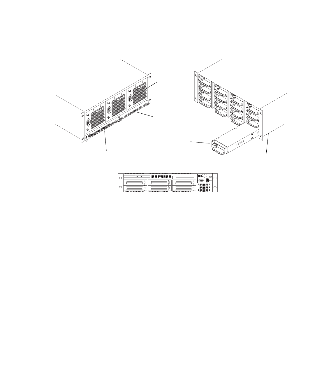
Basic Avid Unity ISIS Media Network Hardware
Hardware Overview
Rear view
Power supply
ISIS Integrated Expansion switch (IXS)
Avid unity ISIS Storage Blade ISB
ISIS Integrated Switch (ISS)
System Director front view
Front view
Engine
Although there are many pieces of equipment are needed to create, connect, and use an
Avid Unity ISIS media network, the major components needed to create the system are a
System Director, an engine containing ISIS Integrated Switch (ISS), ISIS Expansion Switch
(IXS), ISIS Storage Blades (ISB), and one or more clients.
The following sections explain these components and some basic client configurations:
• System Director
• Second System Director
• Engine
• Client
• Maximum Configurations
• Basic Avid Unity ISIS Media Network Configurations
• Supported Cabling
17
Page 18
Chapter 1 Avid Unity ISIS System Overview
System Director
The System Director is 2U in size (see “System Director Front View” on page 18) and
manages the metadata by storing directory information and file attributes. The System
Director does not store actual data, that is stored on the ISBs within the engine.
n
n
The System Director password is preset to is-admin.
You can have two System Directors configured in a redundant configuration, one Active the
other Standby. If the Active System Director goes down, the Standby System Director takes
over. You need at least one System Director to run the Avid Unity ISIS system.
n
System Directors and clients must be Time-of-day Synchronized with Clients and Servers.
The System Director provides a location to coordinate file access modes (read/write), file
locking, range locking, performance data collection, logging, file lookup, and directory
change tracking for client systems. Examples of what the System Director is able to provide
to a client or storage element are:
• Identity of all storage elements connected to the system
• Information about the ISS and IXS modules in the configuration.
• List of workspaces to include name and their unique ID number
• List of users and groups within the system
• Identity of all System Directors in the system (if you have more than one System
Director)
The System Director Front Panel
RAID disk (ID 1)
System disk (ID 0)
18
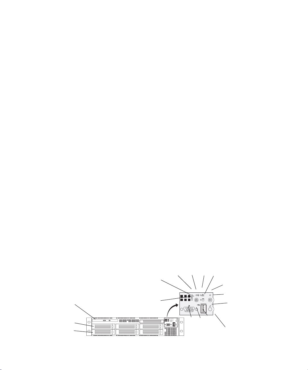
The following figure shows the front view and control panel of the System Director.
System Director Front View
DVD /CD -ROM
DE
B
A
C
L
K
F
G
H
I
J
Control panel
Page 19
Hardware Overview
The following table describes the control panel shown in the previous figure.
System Director Control Panel
A Power/Sleep button G System ID LED
B NIC 2 activity light H System ID button
C NIC 1 activity light I System reset button
D Power/Sleep LED J USB 2.0 Connector
E System status LED K Recessed NMI button (need tool)
F Hard drive activity light L Video connector
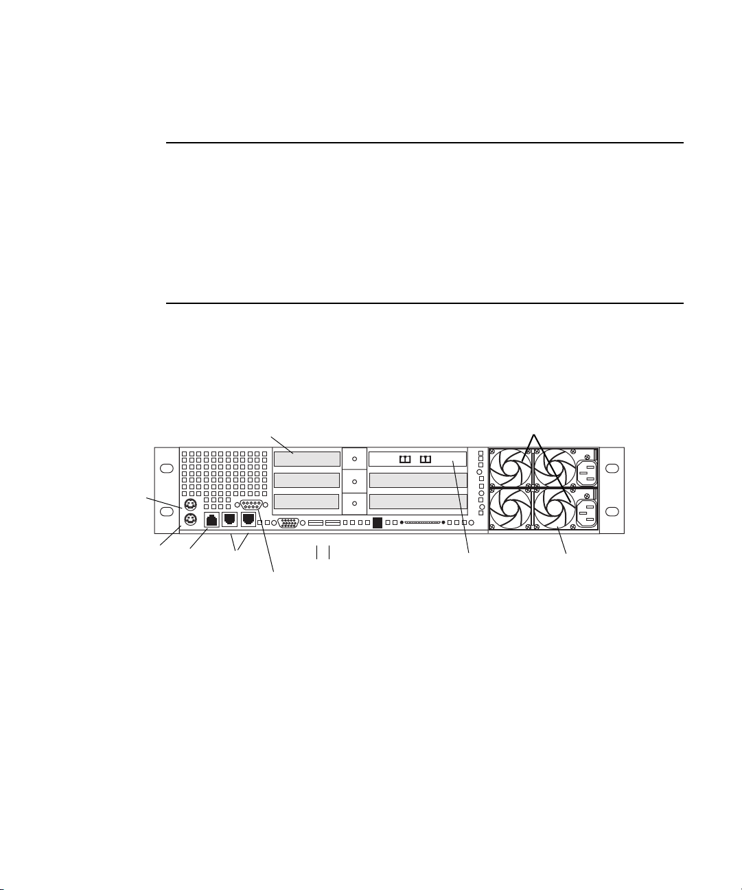
The System Director Rear Connections
The following figure shows the rear panel of the System Director and the function of each
connection.
Small form factor slots not used
Mouse
PCI Slots
l
Power Supplies
AB
Keyboard
RJ45
to
Serial B
1 Gig
Enet
Video
Serial A to F/C switch if needed
Second System Director
You can purchase a second System Director and configure it on the same subnets as the
original System Director. This provides a redundant System Director that is in constant
contact with the original System Director. The second System Director automatically takes
over if the original System Director fails (called failover).
n
For true redundancy it is recommended that you connect the second System Director to a
different engine than the first System Director.
1
USB
2
SCSI B
Dual NIC Ethernet
Adapter Board
Primary power
supply on bottom
19
Page 20
Chapter 1 Avid Unity ISIS System Overview
Engine
The major function of the engine, with all internal components installed, is to store the data
created during actions performed by clients that are sent through the switches.
The engine contains:
• 16 ISBs, each with 500 GB of storage available in two 250-GB drives. This provides
you with 8 terabyte (TB) of storage per engine. As technology advances, the size of the
disks could increase, allowing the total storage per ISB/engine to increase.
• An ISS that allow connections for clients, a 10-Gb uplink port, an engine interconnect,
and a management port for configuration. See “Two Integrated Ethernet Switches” on
page 22.
• An IXS used when you have more than two engines (need an IXS for each subnet),
allowing you to connect multiple engines. See “Two Integrated Ethernet Switches” on
page 22.
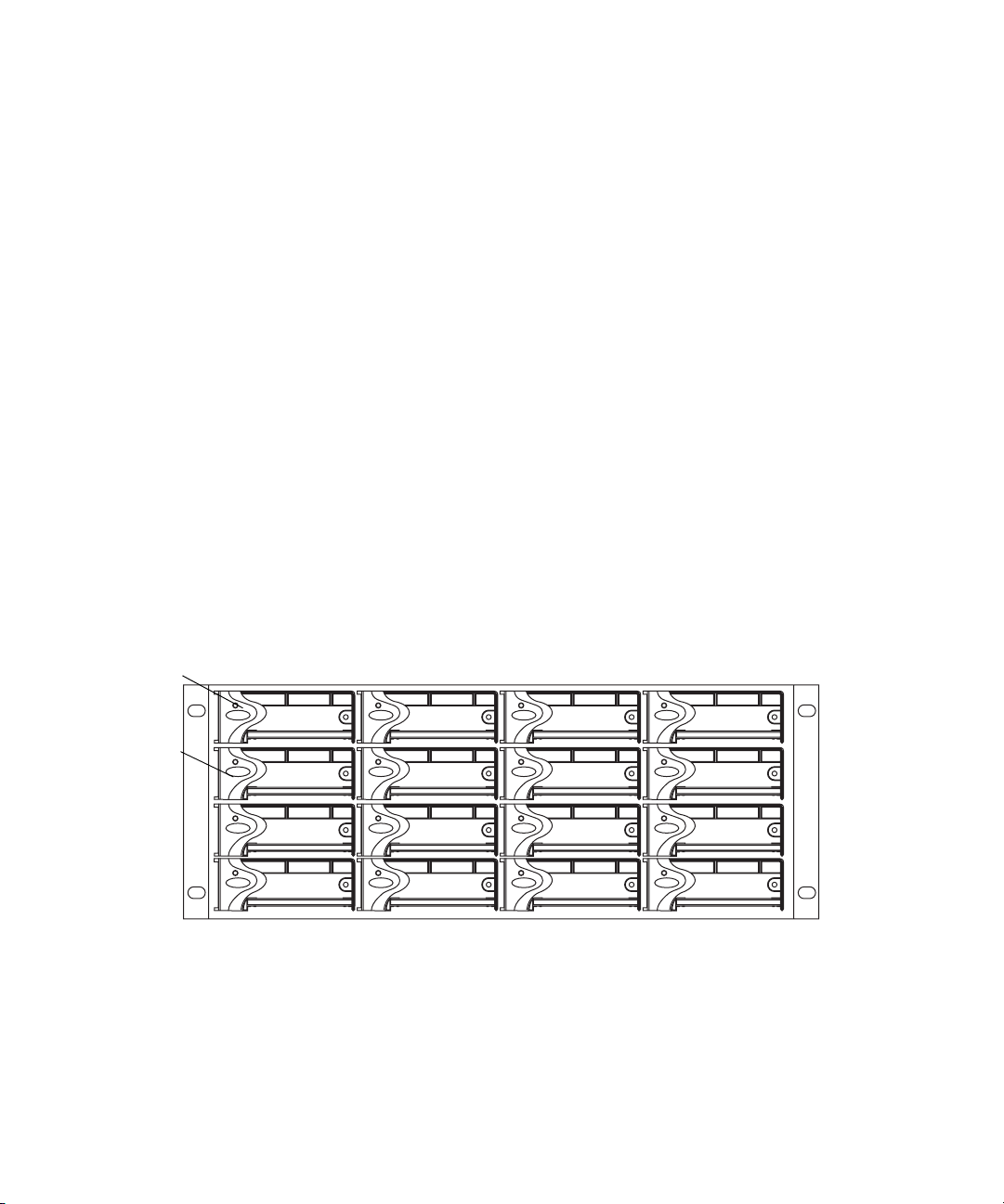
Engine Front View
The front of the engine contains the 16 ISBs. The first is in the upper left portion of the front
and the last ISB is in the lower right.
n
20
Engine Front View
First ISB
Fifth ISB
Each ISB can be removed and replaced separately with the power on. If you replace an ISB
with power on, the LEDs in all of the ISBs go off momentarily. This does not represent a
problem. All functions are still active and working properly.
See the remaining chapters in this document for complete information regarding rack
mounting, Ethernet switch connections, and drive removal and replacement.
Page 21
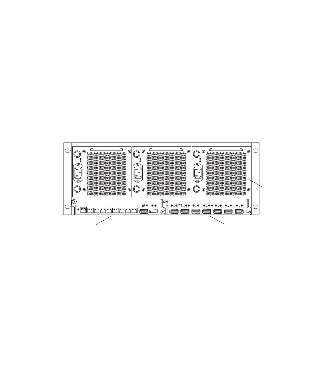
Engine Rear View
The following figure shows the rear of the engine in a configuration that contains the
following:
• Three power supplies (with fans)
• Integrated Switch blade (ISS)
• Integrated Expansion Switch Blade (IXS)
Hardware Overview
n
Three Power Supplies
In a basic configuration containing two engines, each of the engines contains two ISS
modules. The IXS module is used with an ISS module in an engine only when the
configuration goes beyond two engines.
Engine Rear View
ISS module IXS module
The power supplies not only provide power, but they also contain fans that cool the system.
The system only needs two of three power supplies to supply the needed power to function
properly. You can remove and replace a power supply temporarily while the system is
running if one fails.
Power
supplies
21345678
c
w
You should leave the failing power supply in place until you replace the failing power
supply. Replace the power supply as soon as possible to maintain the proper airflow. Do
not remove the failing supply until immediately before you replace it.
Only trained Avid technicians should remove and replace the power supply while the
system is running. Since power to the system is still applied internally to the midplane
you must always keep your hands external to the engine when a power supply is
missing from the engine.
21
Page 22

Chapter 1 Avid Unity ISIS System Overview
Two Integrated Ethernet Switches
The two integrated Ethernet switches, ISS and IXS, serve different purposes and contain
different types of connections.
You must have at least two switches in each engine for the system to operate.
ISS Module
The connections on the ISS module are used for the following:
• Management connection — used to configure the Avid Unity ISIS engine hardware
during installation. This information is used by Avid representatives to originally
configure your system before turning it over to you.
• 1-Gb (RJ-45 cable) — direct connect for clients and the System Directors.
• High speed engine interconnect (CX-4 cable) — proprietary Avid bus that connects
switch blades between engines allowing subnets to connect between the engines.
• 10-Gb XFP MSA form factor transceiver (for Optical cable) — used to connect a 10-Gb
connection on a switch for connecting more clients.
w
Only an Avid recommended XFP transceiver should be used in the 10-Gb XFP
connection, and only Avid trained representatives should remove and replace the XFP
transceiver. Currently supported XFP are the Picolight XFP and Foundry XFP.
ISS Connections
Link
Activity
Link
10-Gb connectionHigh speed
Connection
Status
Activity
21345678
1-Gb connectionsManagement
engine Interconnect
22
Page 23

Hardware Overview
IXS Module
The IXS is needed only if you are connecting three or more engines. It is used in the engine
with an ISS module. The connections on the IXS module are used for the following:
• Management connection — used to configure the switch during installation and monitor
switch functions.
• High speed engine interconnect — proprietary Avid interconnection that stacks the
switches to create one large virtual switch.
IXS Connections
n
Client
n
Management
connection
Engine interconnections
In a basic configuration containing two engines, each of the engines contains two ISS
modules. The IXS module is used with an ISS module in an engine only when the
configuration goes beyond two engines.
A client uses services provided by the Avid Unity ISIS architecture. The client system, using
a 1 Gb Ethernet connection, communicates with the ISBs through the ISS to create, modify,
and read files stored in the actual ISB.
MediaManager clients are the only clients that have been tested with two NIC connections,
one to each subnet.
Activity
Link
A client uses mechanisms specific to a Windows operating system to display, create, and
delete files within the Avid Unity ISIS media network system. For example, when viewed
from a Windows operating system, the system sees a server containing many shares that are
mapped to drive letters.
23
Page 24
Chapter 1 Avid Unity ISIS System Overview
Maximum Configurations
The maximum number of clients and the maximum amount of storage available at this time
are:
• The maximum number of connections are (other than an System Director and engine) is
100. This is normally looked at as the maximum number of clients, including Avid
AirSpeed devices, being 100.
• A fully populated Avid Unity ISIS system can contain 64 terabytes of storage connected
to two subnets. You would need 8 engines containing 128 ISBs, each containing two
250 GB drives per ISB to reach the 64 terabyte level.
n
A System Director must be attached to both subnets, but can only be attached once to each
subnet.
Basic Avid Unity ISIS Media Network Configurations
The following four examples show different types of Avid Unity ISIS configurations.
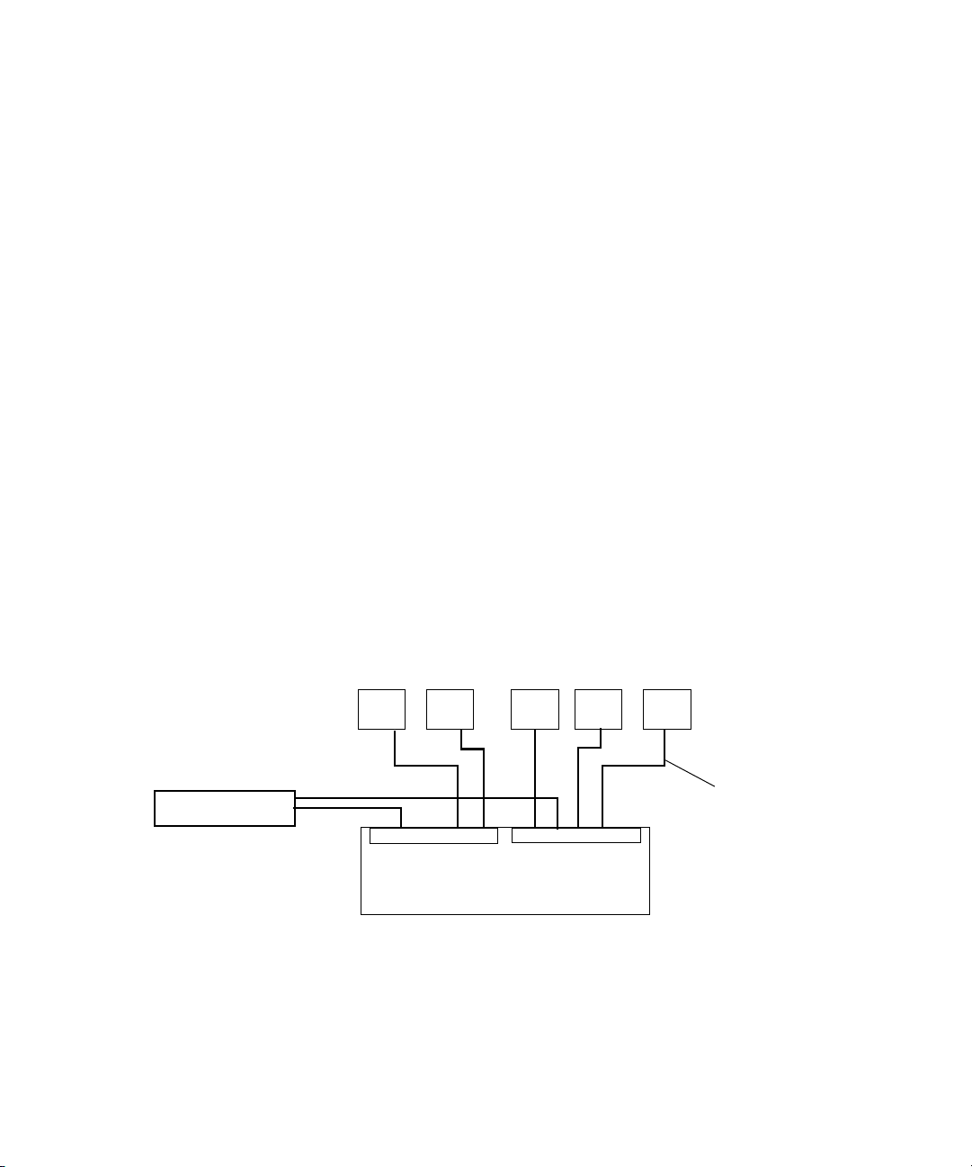
A ZONE 1 (direct connect) configuration consists group of clients connected directly to the
1-Gb connections of the ISS in the engine. The System Director also connects to the both
subnets via both ISS modules using a 1-Gb port.
ZONE 1 Avid Unity ISIS Media Network Configuration
Client
ISS
System Director
Client
ISS
Client
Client
Engine
Client
1-Gb Ethernet
24
A ZONE 2 (indirect connect) configuration consists of group of clients connected to an
Ethernet switch with a 10-Gb port connected to an ISS located in the engine. The System
Director also connects to the both subnets via both ISS modules using a 1-Gb port.
Depending upon the switch configuration, each client shown connected to the external
switch is connected to one of the two subnets through one of the two 10-Gb connection.
Page 25
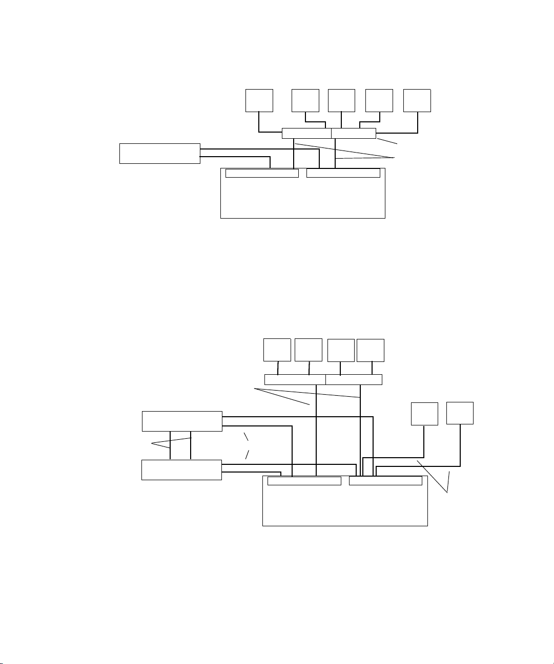
Hardware Overview
ZONE 2 Avid Unity ISIS Media Network Configuration
Client Client Client Client Client
VLAN 1VLAN 2
Switch with 2 10-Gb Ports
System Director
ISS
ISS
Engine
Two 10-Gb Ports
A mixed configuration (Zone 1 and Zone 2) of clients consists of group of clients
connected directly and indirectly to an engine through a switch blade. Also shown are two
System Directors that connect to the engine via two separate ISS 1-Gb ports for use as a
redundant System Director in case of a failure. Both System Directors also connect to each
other through the onboard Ethernet connections to monitor if one of the System Director
fails.
n
Client
ISS
VLAN 1VLAN 2
Engine
ClientClient
1-Gb Ethernet
Switch with two 10-Gb Ports
Client
ISS
Client
1-Gb Ethernet
Failover
connections
Client
10-Gb
Por ts
System Director
1-Gb Ethernet
System Director
Although it is not show in the above diagram, to ensure high availability, whenever possible,
the System Directors should be connected to two different subnets through two different
engines.
25
Page 26
Chapter 1 Avid Unity ISIS System Overview
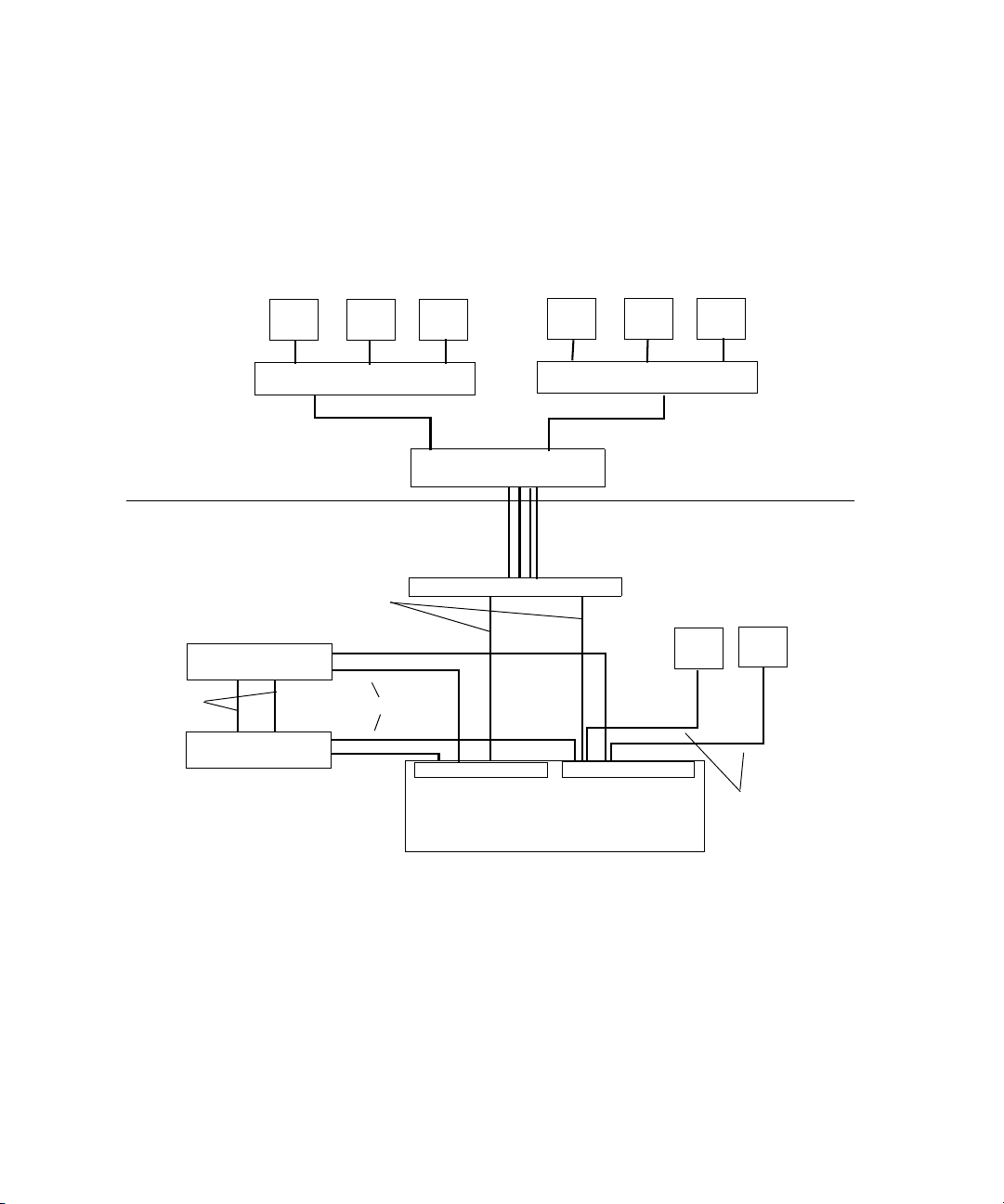
A ZONE 3 (indirect connect) configuration consists of group of clients normally connected
to an Edge access Ethernet switch.
This switch is normally connected to a core switch that has uplinks that connect to the Avid
Network through an Ethernet switch that contains a 10-Gb port connected to an ISS located
in the engine. The System Director also connects to the both subnets via both ISS modules
using a 1-Gb port.
Corporate network
Avid network
Failover
connections
System Director
System Director
Client ClientClient
10-Gb
Por ts
1-Gb Ethernet
Core switch
VLAN 20
ISS
Client ClientClient
1-Gb Ethernet
VLAN 10
Engine
Switch with two 10-Gb Ports
Client
ISS
Client
1-Gb Ethernet
26
Page 27

Supported Cabling
Avid supports the following cable types for connecting a Avid ISIS system.
Supported Cables
Cable Name Function Maximum Distance
Hardware Overview
Avid engine Interconnect
CX-4 cable. Only
available from Avid.
RJ45 Cat 5E or Cat 6
Ethernet cable (minimum).
Cat5 cable is not supported
for these connections.
Optical (XFP) cable.
The Optical (XFP) cable is
an international Class 1
laser product per IEC
60825-1 Amendment
2(2001) and IEC 60825-2
1997. Operating this
product in a manner
inconsistent with intended
usage and specification
may result in hazardous
radiation exposure.
Connect engines. See Avid
Engine CX-4 Interconnect Cable
for proper removal.
Connect management port to
laptop,
Connect System Director to an
ISS, connect two System
Directors Ethernet boards,
connect client to 1 Gb ports on
an ISS.
Connect 10 Gb port of switch to
XFP optical 10 Gb port on the
engine.
3 supported lengths at this time:
1, 3 and 5 meters
100 Meters; If using CAT5E the cable must be
rated for 350 MHz for maximum length.
The maximum length of the cable is defined by the
micron and modal bandwidth.
Avid supports two lengths of the 850 nm cable for
short hauls:
• MMF 62.5 micron cable Modal = 200 at 33
meters
• MMF 50 micron cable Modal = 2000 at 300
meters
Avid supports the 1310 nm cable for long hauls:
• SMF ITU G.652.A/B 9 micron cable up to 10
km
Transceivers, X2 and XFPs
Cisco 4948 uses X2s, not XFPs
Foundry FESX 424 XFP
ISIS ISS XFPs
X2 and XFP names
SC to SC, X2 = Cisco X2-10GB-SR for MMF
X2 = Cisco X2-10GB-LR for SMF
LC to LC,XFP = 10G-XFP-SR for MMF
XFP = 10G-XFP-LR for SMF
LC to LC, XFP = Foundry 10G-XFP-SR
or Pico-light XXL-SC-S45-21 for
MMF.
XFP = Foundry 10G-XFP-LR
or Bookham 10G-BASE-LR for
SMF
27
Page 28
Chapter 1 Avid Unity ISIS System Overview
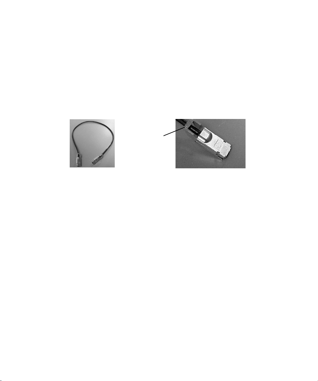
Connecting the Engine CX-4 Cable
Connecting the engine CX-4 interconnect cable to the connector at the rear of the system is
straight forward.
To connect the cable:
t Place it in the connector at the rear of the system.
You hear a snap, and the cable is connected.
Avid Engine CX-4 Interconnect Cable
Cable disconnect
c
n
Damage can occur when disconnecting the Avid engine Interconnect cable from the
switch board if not done properly.
Care should be taken to reduce strain on the ISS switch blades by organizing and dressing
the ethernet cables and CX-4 cables. When dressing the cables do not block removable
switch and power components.
Removing the Avid Engine Interconnect Cable
c
If you attempt disconnect the cable by pulling the blue cable release towards you and
pulling the cable out from the connector at the same time you can cause the cable and
or connector to be damaged. The following explanation and illustration explain how to
properly remove the engine interconnect cable.
To remove the Avid Engine Interconnect Cable from the Rear Connector:
1. While the cable is in the connector, use your bottom hand to grab the cable (or the metal
portion of the connector) and push the cable (or metal portion of the cable) towards the
connector at the rear of the engine.
2. While keeping the pressure towards the engine connector using the cable (or the metal
portion of the connector), use the top hand to pull the blue portion of the cable directly
back. This dislodges the connection of the cable from the connector.
28
Page 29

Pull back on
blue cable release
Push cable or metal
towards engine
3. Pull back with both hands to remove the cable.
Hardware Overview
29
Page 30

Chapter 2
Connecting the Equipment
This chapter explains how to rackmount and connect the system hardware. To do this, a
system installation check list is provided to help you perform the installation in the correct
order. The installation check list continues past the information in this chapter and points
you to the correct area in this document or the ReadMe file to continue the installation.
c
Prior to installing and connecting the equipment in racks, you must use the
Avid Unity ISIS Site Preparation Guide for explanation of power and other installation
needs.
This chapter contains the following information:
• Connecting Power to Equipment
• Rack-Mounting the Equipment
• Installing IXS and ISS Switches
• Connecting the Application Key
• Connecting the Engine
• Configuring a Failover System Director
Connecting Power to Equipment
The Avid Unity ISIS hardware includes three power supplies using an N+1 configuration for
redundancy. The three power supplies “load share” to allow the balanced distribution of ac
power into each Avid Unity ISIS engine. Usually, a minimum of two of the three power
supplies must be operational at one time for the engine to function properly. Each power
supply contains fans and provides a physical function having to do with airflow for the
engine. If a power supply fails, leave it in place until you have a replacement.
Avid recommends that each power supply be provisioned with at least 5 amps of current
capacity per power cord (120 Vac). This allows the system to continue running if one of the
three power supplies fails, with the two remaining load-sharing power supplies drawing
slightly less than 10 amps.
Page 31

Connecting Power to Equipment
n
c
Do not actually connect the power cords to the engines until told to do so in chapter 3.
Use this section to determine how you should connect power to the engines. Place the
power cords into the engines when you place them into the rack as explained in “Rack-
Mounting the Equipment” on page 34, but do not plug them into the outlets until told
to do so later in the document.
See the following sections:
• Three 20-Amp AC Circuits for Three Engines
• Three 20-Amp AC Circuits for Two Engines
• Two 20-Amp AC Circuits for Two Engines
Three 20-Amp AC Circuits for Three Engines
When you are using three 20-amp circuits for three engines, they are configured as follows:
• Each Avid ISIS engine — Each engine has three power supplies; Each power supply is
rated at 5 amps input at 120 Vac. You can have up to one power supply from each of the
three engines on one 20-amp circuit.
n
Each System Director has up to two power supplies rated at 5.8 amps each. Each System
Director includes two power supply. Use one 20-amp circuit for each System Director.
An engine can operate on two power supplies for a period of time to allow you to protect
data. The following illustration shows an example of how the power should be connected to
protect data.
31
Page 32

Chapter 2 Connecting the Equipment
Basic Power Connection for Three ISIS Engines
System Director
Slot 3
Slot 2
Slot 1
20 Amp
System Director
A
A
Slot 3
Slot 2
Slot 1
BC
B
B
20 Amp
C
CA
Engine
Engine
Engine
20 Amp20 Amp
Three 20-Amp AC Circuits for Two Engines
20 Amp
32
n
When using three 20-amp circuits for the engine, they are configured as follows:
• Each Avid ISIS engine — Each engine has three power supplies; Each power supply is
rated at 5 amps input at 120 Vac. You can have up to three power supplies from two
different engines on one 20-amp circuit.c
Each System Director has up to two power supplies rated at 5.8 amps each. Each System
Director includes two power supplies. Use one 20-amp circuit for each System Director.
An engine can operate on two power supplies for a period of time to allow you to protect
data. The following illustration shows an example of how the power should be connected to
protect data.
Page 33

Connecting Power to Equipment
First Example of Power Connection for Two ISIS Engines
System Director
System Director
n
The 20-amp circuits shown for the System Directors should remain the same for both the
three and two 20-amp circuit examples.
AB
Slot 3
Slot 2
Slot 1
Slot 3
Slot 2
Slot 1
C
Engine
CAB
Engine
Two 20-Amp AC Circuits for Two Engines
c
The following configuration is not recommended by Avid, but some locations might
need to connect in this manner.
20 Amp
20 Amp
20 Amp20 Amp 20 Amp
n
When using two 20-amp circuits for the engine, they are configured as follows:
• Each Avid ISIS engine — Each engine has three power supplies; Each power supply is
rated at 5 amps input at 120 Vac. You can have up to three power supplies from two
different engines on one 20-amp circuit.c
Each System Director has up to two power supplies rated at 5.8 amps each. Each System
Director includes two power supply. Use one 20-amp circuit for each System Director.
An engine can operate on two power supplies for a period of time to allow you to protect
data. The following illustration shows an example of how the power should be connected to
protect data.
33
Page 34

Chapter 2 Connecting the Equipment
Second Example of Power Connection for Two ISIS Engines
System Director
System Director
n
The 20-amp circuits shown for the System Directors should remain the same for both the
three and two 20-amp circuit examples.
AA
Slot 3
Slot 2
Slot 1
Slot 3
Slot 2
Slot 1
B
Engine
BAB
Engine
Rack-Mounting the Equipment
20 Amp
20 Amp
20 Amp20 Amp
This chapter describes how to install and connect the System Director and other workgroup
hardware.
c
Information concerning power, airflow, and dimensions are explained completely in the
Avid Unity ISIS Site Preparation Guide located on the documentation DVD. You should
understand the basic power configurations explained in “Connecting Power to
Equipment” on page 30.
c
Before you start the procedures in this chapter, you should be familiar the previous
chapters in this document.
Rack-Mounting Examples
Avid supports more than one Avid Unity ISIS rack configuration. You should have discussed
the layout for your system with an Avid representative prior to purchase.
The following examples show a few of the supported rack configurations.
34
Page 35

System
Director
Engines
Rack-Mounting the Equipment
Single Rack - Two Engines - One System Director
35
Page 36

Chapter 2 Connecting the Equipment
Single Rack - Four Engines - One System Director
Foundry switch
System Director
A B
IXS
21345678
21345678
MGMT
STATUS
21345678
MGMT
STATUS
21345678
TUS
21345678
MGMT
STA
21345678
MGMT
STATUS
Engines
36
Page 37

Dual Rack - Four Engines - Failover System
Rack 1 Rack 2
Foundry switch
Rack-Mounting the Equipment
System
Directors
MGMT
STATUS
21345678
S
21345678
MGMT
STATU
21 345678
21345678
21345678
MGMT
STATUS
Installing Rack-Mount Rails and Brackets
All Avid Unity ISIS rack-mount components are supplied with either mounting rails or
brackets. You should follow the manufacturer’s installation instructions supplied with each
component to correctly attach the rails or brackets to the rack rails.
n
Where necessary, this guide supplies specific rack-mount rail or bracket installation
instructions. These instructions supersede the manufacturer’s instructions.
TUS
MGMT
STA
Engines
21345678
37
Page 38

Chapter 2 Connecting the Equipment
Installing System Director and an Avid ISIS Engine
The System Director and storage elements are placed into a rack for easy access to the
cables, connectors, and drives. The following list provides recommendations you should
take into account prior to rack-mounting Avid Unity ISIS equipment:
• The heaviest equipment should go at the bottom of the rack, for example, the
Avid Unity ISIS engine.
• Lighter equipment goes towards the middle and top of the rack, for example, System
Directors, a Keyboard, monitor, and mouse assembly (KMM), with Ethernet switches at
the top of the rack.
• If the rack is provided with stabilizing devices, install the stabilizers before mounting
the equipment in the rack.
• Avid recommends that you leave a 1U or .5U space between each piece of equipment
mounted in the racks. This allows for better airflow and cable access, and helps stop
vibration in any equipment being transferred to spaces above and below.
• Avid recommends that you leave an 8 to 12 inch space at the bottom of the rack. This
allows for better airflow and lowers the possibility of dust or dirt being picked up by the
devices.
• If you have a redundant configuration, you might place equipment in different racks.
Place the System Director and Failover System Director in different racks, separate the
storage elements between racks, place redundant Ethernet switches in different racks,
and have the power from each rack connected to different circuits.
• For normal operation, you’ll need to maintain approximately 2 feet (0.6 meters) of open
space in front of and behind the rack. This allows free access to the components in the
rack for operating changes or adjustments. For service, you need approximately 3 feet (1
meter) of open space in front of the rack and 2 feet (0.6 meters) of open space behind the
rack. This allows for the removal of any component that needs to be replaced.
n
For more information related to rack mounting a Avid Unity ISIS system, see the
Avid Unity ISIS Site Preparation Guide online on the Avid Knowledge Base or the online file
on your Avid Unity ISIS system DVD.
Mounting the Engine
w
38
Lifting the engine with the blades and power supplies installed can cause an injury.
The engine must have the blades and power supplies removed prior to lifting. Avid
recommends that two persons should be used whenever lifting the empty engine.
Page 39

Rack-Mounting the Equipment
To mount the engine into the rack:
1. Screw the brackets to the rear of the rack as shown in the following figure.
Connecting Rear Brackets
Rear
2. Make sure that the blades and power supplies are not in the engine.
3. Two persons lift the engine and place the rear of the engine onto the brackets as shown
in the following figure.
Mounting the Engine
4. Screw the engine to the front of the rack through the ears of the engine as shown in the
preceding figure.
39
Page 40

Chapter 2 Connecting the Equipment
Installing Blades and Power Supplies
Once the engine has been mounted you should follow the instructions listed below.
To place the power supplies and blades into the engine:
1. Unpack each ISB and turn it so you can properly read the Avid name.
2. Place the ISB into the slot and slowly push the ISB into the slot until you hear a click.
3. Repeat from Step 1 until all blades are installed.
4. Carefully unpack each power supply.
w
40
Avid recommends that two persons be used to install the power supplies. You could be
injured if you dropped a power supply on any part of your body.
5. Place the power supply into the engine as shown in the following figure and slowly push
the power supply into the slot.
Screws
6. Turn the screws until tight.
7. Repeat from Step 4 until all power supplies are installed.
Page 41

Rack-Mounting the Equipment
w
Only trained Avid technicians should remove and replace the power supply when
power is applied to the system. Since power to the system is still on, you must always
keep your hands external to the engine when a power supply is missing from the
engine.
Installing IXS and ISS Switches
The location of the ISS and IXS switches in the stack are very important.
If you have only one or two engines you should only be installing ISS switches into the
engines, see “Two-Engine Connections” on page 44.
If you have more than two engines you need two IXS switches on different sides of the
stack. For example; one IXS would go in the left side of the first engine and the other IXS
into the right side of the second engine.
The IXS should always be in the first engine at the top of the stack and the second engine
from the top of the stack, see “Four-Engine Connections” on page 45.
Unpack the switches and place them into the slides internal to the engine. Carefully push the
switch into the midplane of the system until the connection is made.
Installing Switches into an Engine
ISS
41
Page 42

Chapter 2 Connecting the Equipment
Connecting the Application Key
Before you connect the System Director to the system, you need to connect the
Avid Unity ISIS system USB application key (also called a dongle). The USB application
key determines how many Avid Unity ISIS clients can simultaneously use your system.
c
c
Do not lose the USB application key. Your Avid Unity ISIS system does not function
without it. If you lose the USB application key, you must purchase another one from
Avid to us e your Avid Unity ISIS system software.
To connect the application key to your Avid Unity ISIS system:
1. Locate the USB application key in your Avid Unity ISIS system kit.
2. Attach the USB application key to one of the rear USB ports of the System Director; see
“The System Director Rear Connections” on page 19.
Do not use the built-in USB connector on the front of the SR2400 File Manager.
Connecting the Engine
You n ow physically connect the engines to each other. Then you logically connect them as
you configure the addresses for each engine. See “Configuring Avid Unity ISIS Hardware
and Installing Software” on page 49.
c
You should connect power cords to the equipment, but do not plug them in until told to
do so in “Configuring Avid Unity ISIS Hardware and Installing Software” on page 49.
When configuring the engines, you need power to be turned on at the proper time.
You will need the following:
42
• PC (laptop or System Director)
• Cat5E or Cat6 Ethernet cable to run between the PC and the Management port of the IIS
or IXS
• Two or more engine Interconnect cables if you are using more than one engine
• System Director DVD/CD ROM
Page 43

Physically Connecting Engines
Physically connecting an Avid Unity ISIS system is different in many ways, but one of the
major differences is the type of switch blade placed into the engine.
• ISS: Only the ISS blades are used when you are connecting two engines.
• IXS: When connecting three or more engines, you must use at least two IXS blades (one
in each subnet) to connect each engine.
Use the following list to help you when you connect the System Director, laptop for
configuration, and clients to the Avid Unity ISIS system.
• The laptop/system shown in the following examples is used for configuring the engine
at the beginning of the installation or for maintenance by an Avid representative. You
can use the 1-Gb connection on the System Director for configuring the engine at the
beginning if needed, but do not leave it connected or use it for a maintenance
connection.
• When you are connecting the System Director to the ISS module using the DUAL NIC
module, Avid recommends that you connect the A connection to the left side of the
engine and the B connection to the right side of the engine. This allows the A side to
correspond to the lower number subnet, 10, and the B side to the higher number subnet,
20. However, it also functions properly the other way.
Connecting the Engine
n
n
• All clients connected to the switches on the left side of the box are connected to one
subnet, while clients connected to the switches on right side of the box are connected to
the second subnet. See “Connecting the Application Key” on page 42 for more
information.
When physically connecting more than two engines at the rear of in the system you should
only connect the left side interconnects of the system for the initial configuration. Chapter 3
explains when and how to connect the remaining right side of the system.
• All connections in the following two examples should be considered as directly
connected to the client system and not connected through switches.
The following examples show how to physically connect an engine to a System Director and
clients. These illustrations are designed for explaining cabling, not for proper positioning in
the rack.
43
Page 44

Chapter 2 Connecting the Equipment
Basic Two- and Four-Engine Connections
The following figures show the connections for two engines and four engines.
n
The connection from the A portion of the Ethernet board should go to the left side of the
engine (from the rear) and always start at connection 1. The connection from the B portion
of the Ethernet board should go to the right side of the engine (from the rear) and always
start at connection 1.
Two-Engine Connections
To client - RJ45 connector, CAT 5E or CAT 6
Inter-engine
connection - CX4 connector
Avid cable
RJ45 connector,
CAT 5E or CAT 6
System
Director
or
Laptop
for config
only
Connection 1
S
U
T
A
T
MGMT
S
S
U
T
A
T
MGMT
S
Left side
21 345678
21 345678
S
U
T
A
T
MGMT
S
S
U
T
A
T
MGMT
S
Right side
21345678
21345678
44
AB
Page 45

Four-Engine Connections
Connecting the Engine
System
Director
or
Laptop
for config
only
IXS
MGMT
STATUS
Left side
21345678
21 345678
21345678
TUS
21345678
MGMT
STA
Right side
Inter-engine connection
RJ45 connector,
CAT 5E or CAT 6
Management port
connetion
IXS
S
MGMT
STATU
21 345678
TUS
MGMT
STA
21345678
AB
45
Page 46

Chapter 2 Connecting the Equipment
Configuring a Failover System Director
c
Failover configurations do not work unless you unassign the Windows XP IP Security
policy.
To unassign the IP Security Policy:
Overview
You need to perform two functions to enable a failover system for Avid Unity ISIS:
• Physically connect two systems for failover (using straight or crossover cable); see
• Enable the software on both systems; see “Enabling the Failover Software” on page 75
1. Select Start > Control Panel
2. Double-click Administrative Tools.
3. Double-click Local Security Policy.
4. In the left pane, double-click the IP Security Policy on Local System.
5. Right click IP Security Policy”and select Unassign.
“Physically Connecting System Directors for Failover” on page 47
for instructions on enabling the software for failover systems.
46
Page 47

Configuring a Failover System Director
Physically Connecting System Directors for Failover
The following figure shows how the two System Directors are connected to allow for a
failover configuration.
AB
AB
2
1
n
S
U
T
A
T
MGMT
S
S
U
T
A
T
MGMT
S
21345678
21345678
S
U
T
A
T
MGMT
S
S
U
T
A
T
MGMT
S
21345678
21345678
Connect the two System Directions under the following conditions:
• After you have physically configured the system and loaded the Avid Unity ISIS
software on both System Directors.
• When the server software is Off on both systems.
• The connection from the A portion of the Ethernet board goes to the left side of the
engine (from the rear) and always starts at connection 1. The connection from the B
portion of the Ethernet board goes to the right side of the engine (from the rear) and
always starts at connection 1.
Each System Director must connect to right and left sides of the engine to allow both of the
System Directors to reach the two internal subnets.
47
Page 48

Chapter 2 Connecting the Equipment
48
Page 49

Chapter 3
Configuring Avid Unity ISIS Hardware and Installing Software
This chapter describes how to connect and configure the System Director and other
Avid Unity ISIS hardware. Since the number of different configurations are endless, it uses a
configuration with four engines and one System Director as an example.
If you have questions, please call your Avid representative or your local ACSR.
c
Before you start the procedures in this chapter, you should be familiar with the
information in previous chapters and the Avid Unity ISIS Site Preparation Guide.
This chapter contains the following sections:
• IP Addressing Overview
• Configuration Overview
• Configuring the Engine
• Installing System Director Software
• Performing Basic Administrative Functions
Page 50

Chapter 3 Configuring Avid Unity ISIS Hardware and Installing Software
IP Addressing Overview
Before you attempt to define a total IP addressing scheme for your system and configure the
static internal IP addresses of the engine, you should have a solid understanding of how the
addresses are assigned within the engine and how the IP addresses increment between
engines.
n
192.168.10.10 and 192.168.20.10, subnet 10 and subnet 20, are used by Avid as examples
throughout this document, your site might require different addresses. Consult with your
site’s networking managers for site specific requirements. Unless specified, you can change
the addresses used in the following example to suit your needs. However, whichever static IP
addresses are assigned within the engine, they must not be assigned by a DHCP server to
any other device within the Network.
The following figure shows the front and rear of a engine. You should use this figure, the list
following the figure, and the illustration, “Static Engine Internal IP Address Assignments”
on page 52 to understand how static IP addresses are assigned to each engine.
Front and Rear of a Engine
Upper left
Front
Lower right
Management Port
21345678
Left side
(Default subnet 10)
Management Port
Rear
Right side
(Default subnet 20)
The IXS shown is only used
when three or more engines
are connected.
50
Page 51

IP Addressing Overview
The following list describes what needs to be accomplished to assign IP addresses to
engines. You should understand the assignment of IP addresses completely before you
perform the actual configuration.
n
n
n
Do not attempt to assign addresses to the engine using this list. This provides an overview,
not a step-by-step procedure.
• Connect Port 1 of the System Director or a port on a laptop to the Management Port of
the ISS in the bottom engine of the rack using a CAT5 E, CAT6 cable or better. See
“Front and Rear of a Engine” on page 50.
• You are now talking to the Management Port on an isolated network interface on the ISS
using the default IP address of 192.168.0.10. This IP address is used on every the
Management Port on the ISS and expansion switch blade. The address is not on the local
10 or 20 subnets Ethernet bus and is never used to transfer actual data.
When you assign subnet addresses internally and have more than one engine, all ISSs and
IXSs on the left side of the rear of the engine are on one subnet, while all ISSs and IXSs on
the right side of the rear of the engine are on the other subnet.
See figures “Front and Rear of a Engine” on page 50 and “Static Engine Internal IP
Address Assignments” on page 52 for a pictorial view of address assignments explained
below.
• Then two static IP addresses are assigned to the upper left-most ISB slot in the engine
when looking at the engine from the front. The addresses are 192.168.10.10 on subnet
10 and 192.168.20.10 on subnet 20. You are assigning the address to the slot, not the
blade. The ISB can be physically moved, but the IP address remains with the slot.
• As the slots go sequentially from top left to right, over a row and starting at the left
again, each slot is assigned a static IP address that is incremented by one until you reach
the right-most bottom slot that contains addresses of 192.168.10.25 and 192.168.20.25.
• At this point, each ISS or IXS is assigned a base address. One ISS is assigned a subnet
10 address of 192.168.10.26 and the other a subnet 20 address of 192.168.20.26 (unless
the customer wants to change the IP scheme or subnet mask). Now each side of the
engine is assigned 17 addresses on each network for a total of 34 addresses per engine.
• You then increment the subnet 10 and subnet 20 addresses by one and assign them to the
switch blades in the next engine.
• The ISB slots and switches are again incremented.
51
Page 52

Chapter 3 Configuring Avid Unity ISIS Hardware and Installing Software
Static Engine Internal IP Address Assignments
Subnet 10
Subnet 20
52
Page 53

Configuration Overview
You should now have the System Director and all of the engines in a rack (or more than one
rack), interconnect cables connected to the left side, and power cords attached but not
plugged into ac circuits.
You now need to do the following:
1. Configure the engine by assigning IP addresses to the engine. This provides each ISS,
IXS, and ISB with the needed IP addresses to talk to the clients and System Director, see
“Configuring the Engine” on page 54.
Configuration Overview
n
“Configuring the Engine” on page 54 allows you to see the cabling and does not represent
an actual rack configuration.
2. Load the System Director software. This software is used to create a file system on the
System Director, bind the ISBs to the software on the System Director, create Storage
groups, and administer the Avid Unity ISIS system. See “Loading Avid Unity ISIS
software” on page 59.
3. Perform administrative functions: bind ISBs (storage elements), create storage groups,
and do other administrative functions. See “Performing Basic Administrative
Functions” on page 59.
4. Load the client software; see “Loading Client Software for Zone 1 and Zone 2 Clients”
on page 63.
LAN Connections on the System Director
The ghost image on the System Directors does not set the IP addresses of the two onboard
NICs or the dual NICs card on the PCI bus; the system is set for DHCP.
53
Page 54

Chapter 3 Configuring Avid Unity ISIS Hardware and Installing Software
Configuring the Engine
To configure the engine:
1. Make sure the equipment is cabled as explained in “Connecting the Equipment” on
page 30. An example is shown in the following figure. Notice that the engines with the
IXS cards are located on the top of the stack.
Engine Configuration Example
IXS
Left side
21 345678
21 345678
MGMT
STATUS
21 345678
MGMT
STATUS
21345678
TUS
21345678
MGMT
STA
TUS
21345678
MGMT
STA
Right side
Inter-engine connection
for first section
Inter-engine connection
for second section
IXS
RJ45 connector,
CAT 5E or CAT 6
Port 1 connection
to Management port
Power cords not shown
54
Port 1
To monitor
AB
:
Page 55

Configuring the Engine
2. Connect the power cords that are connected to the System Director to the ac circuit and
turn on the System Director.
n
n
The System Director password is preset to is-admin.
3. Plug in at least two of the power cords at the same time that are connected to the engine
attached to the System Director over Port 1. Then connect the third cord. This
automatically places power to the engine. Wait for all the LEDS on the engine to be
green.
Power cords should be plugged into the Engines one at a time when specified in this list. Do
not plug them all in at once.
4. Open a browser and go to the following address:
https:// 192.168.0.10:5015
5. You are asked for the default password. Type:
The Avid ISIS Integrated Switch Blade Window appears.
6. Type the following into the Chassis Configuration window shown following this step.
- The starting IP addresses
- The subnet mask as shown in the screen below
- The Date, Time, and Time Zone.
- The ending IP address should be the last address of the engine in the system.
Remember that each engine has 17 IP derrieres on each side, for a total of 34. Set
the ending address high enough to cover the last engine and any possible near term
future needs.
se-admin
n
n
- If you are going to be using a Zone 3 environment you must set the default gateway
addresses for both sides of the engine. These addresses must come from the
customer’s IS department.
Then click Submit.
There should be no DNS servers connected to the network segments that assign addresses in
the above ranges.
A Dialog box appears with an error warning. It is informational and can be disregarded.
The first crate should now be properly addressed.
55
Page 56

Chapter 3 Configuring Avid Unity ISIS Hardware and Installing Software
n
Add/Remove
The general idea of connecting the system is to inter-connect only the left sides (VLAN 10) of
the engines one at a time as explained below. Once the left side of the stack is completed you
can then return and connect the right (VLAN 20) side.
7. Connect the power cord to at least two of the power supplies at the same time from the
next engine to the ac circuit. Then connect the third power supply. It should take about
two minutes for the engine to come to operational status.
8. Click Add/Remove Engine in the left Pane.
Add
56
Page 57

Installing System Director Software
9. Click Add.
It will take several minutes for the engine to stabilize. The second engine is now
addressed.
n
n
The addresses in the two engines should be pingable from the from the system connected to
the Management port.
10. Repeat steps 7 to step 9 until all engines are configured with the proper addresses on the
left side of the stack
11. Connect the inter-connect cable from the right side of the stack to the top engine. Thew
switch picks up the addresses from the chassis master (left side of the engine in this
example)
The addresses in the engine should be pingable from the from the system connected to the
Management port.
12. . Repeat step 11 until all the switches on the right side of the stack are connected.
Installing System Director Software
Your System Director and all engines now have power applied with the System Director
attached to both internal subnets of the engine as shown in “Engine Configuration Example”
on page 54.
To install the System Director software you need the Avid Unity ISIS DVD. When you insert
the DVD into the system DVD drive, a dialog box opens.
57
Page 58

Chapter 3 Configuring Avid Unity ISIS Hardware and Installing Software
n
Avid highly recommends that you click the Read Me button. This displays the ReadMe file
that provides the latest information regarding the Avid Unity ISIS system.
To install the software:
t Click the Install Product button.
The Install Products dialog box opens.
The following table describes the Install Products dialog box buttons and their functions.
Install Products Dialog Box Buttons
Button Function
System Director Click this button to install the System Director software on a System Director.
This software allows you to create a file system on the System Director for the
engines; it also provides administration tools and error logging. See “Loading
Avid Unity ISIS software” on page 59on page 58.
Unity ISIS Installers Click this button to “install the installers” (on the System Director) you need to
load the software and firmware of the switches and ISBs of the engines and to
remotely install the Windows client. See “Loading the Installers” on page 59.
Windows Client Click this button to load the software for the Avid Windows client using the
DVD while on the client system. You can also load the client remotely.
Main Menu Click this button to return to the previous dialog box.
58
Page 59

Loading Avid Unity ISIS software
To load the Avid Unity ISIS software:
1. Insert the DVD into the System Director.
The DVD automatically starts. A dialog box opens.
2. Click Install Products.
The Install Products dialog box opens.
3. Click System Director in the second dialog box.
A Setup Wizard opens.
4. Follow the instructions in the Setup Wizard with the following exceptions when the File
Location window opens:
- Select the box that specifies Everyone in the window asking about file location
5. Once the installation is complete, click close.
Loading the Installers
To load the Avid Unity ISIS drivers:
1. Insert the DVD into the System Director.
Installing System Director Software
The DVD automatically starts. A dialog box opens.
2. Click Install Products.
The Install Products dialog box opens.
3. Click Client Installers in the second dialog box.
A Setup Wizard opens.
4. Follow the instructions in the Setup Wizard with the following exceptions when the File
Location window opens:
- Select the box that specifies Everyone in the window asking about file location.
5. Once the installation is complete, click Close.
At this time the System Director software services are operational, but the ISIS file
system is not yet operational.
Performing Basic Administrative Functions
Before you log on and use the Avid Unity ISIS Administrator and load the remaining
software on the engines, you must initialize your system by creating a Active partition on the
System Director main drive.
59
Page 60

Chapter 3 Configuring Avid Unity ISIS Hardware and Installing Software
To create a Active partition:
1. Select Start > Programs > Avid Unity System Director > System Director Control Panel.
Note the Blue Active Mode in the screen below.
2. Click the Configuration Tab.
60
3. Click Stop Server
4. Click Create New Active. The server automatically restarts when complete.
5. If you are not placed in the Status Tab, click System Director Status.
The Standby Mode has changed to Active Mode and the light is Green.
Page 61

Installing Software on the Engines
Upgrading the software on the engines should be done to make sure you have the latest
software on the engines. You can use Web Administrator from anywhere to perform the
following functions, but you usually do it from the System Director:
• Upgrade the ISS and IXS with the proper/latest software
• Upgrade the ISBs with the proper/latest software
• Create Workspaces
To upgrade the software:
1. Go to https://IP address of System Director (or virtual name):5015.
The System Administration Tool opens.
Chassis/Engine
Installing System Director Software
Upgrade
Storage Blades
2. Select Management Menu > Chassis (Engine).
3. Select the chassis you wish to upgrade in the right pane.
4. Click Upgrade Switch Blades.
Upgrade
Switch Blades
The Upgrade Switch Blades window opens.
61
Page 62

Chapter 3 Configuring Avid Unity ISIS Hardware and Installing Software
Tgz file
Upgrade
5. Select the file you want to upgrade, and click Upgrade.
n
Refresh
Upgrading takes a approximately of 25 minutes for one engine. To find out when it has
completed, go to the System Admin Tool, select the engine in the right pane, and click
Details at the bottom of the screen.
Select an engine
Details
n
62
The Status for the upgrade (phases 2 and 3) is shown at the bottom right of the window. You
must continually click the green refresh button next to the engine text above the right pane to
display the changing Status.
When the Status is empty, the upgrade is complete.
6. Repeat steps 2 through 5, substituting only Upgrade Storage Blades for
Upgrade SwitchBlades. This should take approximately 20 minutes depending upon the
number of Storage Blades you have.
Page 63

Loading Client Software for Zone 1 and Zone 2 Clients
Installing System Director Software
n
To use the Avid Unity ISIS Administration Tool you might also need a revision of 1.5.0 or
higher of the Java runtime library. If you do not have that on your, Avid provides it on the
Avid Unity ISIS software DVD in the Java directory. Just go there and click the executable.
You can load the Client software in several ways:
• You can take the DVD to each client separately and load it from the DVD.
• You can store the client software somewhere on the corporate network and allow
everyone who needs the software to gain access to it and load it.
• You can use the a Browser to reach the Administration Tool and load it from the System
Director because it was loaded during the previous installation of the Client Installers.
We only explain the client software installation using a browser. It is explained below.
1. Start a browser.
2. Go to https://IP address of System Director (or virtual name):5015.
The System Administration Tool opens.
Installers
n
3. You are asked for a Password. Ask your Administrator if there is a password.
4. Click the Installers Menu at the top of the right pane.
An Installer Downloads screen opens.
During the client software installation, you are asked by the software if you need the
Compatibility drive loaded. Answer Yes if you have the following software:
•Media Composer Adrenaline — v1.63 - v1.6.7
• Newscutter Adrenaline — v5.6.3 - v5.6.7
• Media Composer Meridien — v12.5
63
Page 64

Chapter 3 Configuring Avid Unity ISIS Hardware and Installing Software
Flash executable
Win32 Client
Installers
5. Click to load the appropriate Flash executable from the right pane.
6. Click Win32Client in the right pane of the window.
n
n
Loading and Configuring Client software for Zone 3 Clients.
The installer might ask you if you want to save or run the installation software, either is
acceptable.
During a WIndows XP installation a question appears asking who the software is for. You
must select “Everyone”.
7. Reboot when asked.
The client software is installed.
Loading clients software for Zone 3 clients is similar to Zone 1 or Zone 2 clients. After
loading the software for Zone 3 clients you need to perform some special configuration
functions.
To load and configure Zone 3 clients do the following:
1. Load the client software as explained in “Loading Client Software for Zone 1 and Zone
2 Clients” on page 63.
2. Do one of the following:
t Double click the Client Manager icon in the Windows taskbar, or right click Client the Manager icon
and select Show Client Manager.
t If the icon is not available, select:
Start> Programs> Avid Unity ISIS> Client Manager.
64
Page 65

Installing System Director Software
3. If the No workspaces found dialog box appears click OK, and the Client Manager
Window opens.
n
Options Menu
4. Select Add Remote Host from the Options menu at top of Client Manager window.
A dialog box appears.
5. Add the Computer names, or IP addresses, (never Virtual addresses) of all System
Directors.
You must add the computer name of both System Directors if you have two.
6. Select Preferences from the Option Menu and a dialog box appears.
7. Select Zone 3 from the Zone Drop Down Menu and reboot when asked.
Client Manager Window
65
Page 66

Chapter 3 Configuring Avid Unity ISIS Hardware and Installing Software
66
Page 67

Chapter 4
Avid Unity ISIS LED Status
This chapter provides an explanation of the light-emitting diodes (LEDs) located on the
different sections of the Avid Unity ISIS engines.
• LED Locations and Colors
• Interpreting LED Error Reporting
• Interpreting Software Installation LED Reporting
• LED Summaries
LED Locations and Colors
LEDs on each ISS and ISB that help you determine if there is a problem with the system and
what type of problem exists. The following illustration shows the location of the Status
LEDs on the ISB and ISS.
LED Locations
Status LEDs
21345678
Avid has designed the LED colors and blinking with the general ideas in mind:
• Green-blinking — System or section is getting ready or is OK
ISB (not to scale)
ISS
Page 68

Chapter 4 Avid Unity ISIS LED Status
• Green-steady — System or section is OK and operational
• Amber-blinking — Minor failures occurring, but not fatal
• Amber-steady — Fatal or almost fatal error has occurred, system or section is not
operational.
The LEDs are used in two major ways:
• Help explain errors
•Explain the different phases of software installation.
Interpreting LED Error Reporting
When determining errors, each LED blinks at one of the following three rates or stays On
(steady).
• Slow: 0.5 Hz
•Medium: 2.0 Hz
•Fast: 5.0 Hz
Interpreting Software Installation LED Reporting
When determining the status of software installation, the LEDs blink at the colors and rates
described in the following table.
Software Installation LED Reporting
Color Blink Status Description
Green Steady No installation being performed
Amber .5 second Installation starting or installation in Phase 0
Amber 1 second Installation in Phase 1
Amber 2 seconds Installation in Phase 2
Amber 3 seconds Installation in Phase 3
Amber Fast Installation failed
68
Page 69

LED Summaries
The following table provides a list that explains if the ISS system is working or which errors
have been detected by the hardware or software.
ISS LED Summary
Color and Speed Status
Amber-steady Xmon and Temperature OK/Not booting yet
Amber-fast Xmon and Temperature critical (>-70C)
Green-slow Xmon:booting Operating System
Green-steady with 5 0ms of black each second CM:Master:OK
Green-steady with 50 ms of amber each second CM:backup:OK
Amber-fast CM:high temp (>60C)
Amber-steady CM:error (followed by reboot)
LED Summaries
(XMON waits for temperature to drop)
The following table describes the LED behavior on an ISB system.
ISB LED Summary
Color and Speed Status
Amber-steady Xmon and Temperature OK/Not booting yet
Amber-fast Xmon and Temperature critical (>-70C)
(XMON waits for temperature to drop)
Green-slow Xmon:booting Operating System
Amber-slow, all ISBs asynchronously CM:No engine configuration
Green-steady CM:OK
Amber-fast CM:high temp (>60C)
a
Amber-steady CM:error
work)
a. Error could be: No critical application, missing critical application, heartbeat problem or
temperature is critical.
(followed by reboot, but might not
69
Page 70

Chapter 4 Avid Unity ISIS LED Status
70
Page 71

Appendix A
Loading the Product Recovery DVD
This appendix describes the procedures to recover your Avid Unity ISIS System Director if
you need to reinstall Avid specific Windows XP.
n
c
This procedure restores only the Windows XP operating system and the hardware drivers. It
does not restore the Avid Unity ISIS software. The Avid Unity ISIS software must be
reinstalled separately, after the operating system recovery is complete.
You might need to reinstall the Windows XP operating system on your System Director if
you are directed to do so by Avid Customer Support or if you are initializing your System
Director on a new drive. The reinstallation offers you two options:
t Perform a Windows XP installation to the entire system (C: and D:). This replaces all
the data from all the available partitions on your System Director. You can perform this
operation if you are initializing your System Director.
You lose metadata if you restore the D: portion of the drive.
t Perform a Windows XP installation to the first partition (C:). This removes the data in
the C: partition only; the D: partition is not changed. You can perform this operation to
replace only the operating system on your System Director.
Reinstalling the Windows XP Operating System
To reinstall the Windows XP operating system from the Avid Product Recovery DVD:
1. Make sure to unmount any workspaces the clients have mounted.
2. Stop all clients.
3. Use the Administration Tool to stop the System Director.
4. Locate the Avid Unity ISIS System Director Product Recovery DVD.
5. Insert the Avid Unity ISIS System Director Product Recovery DVD into the System
Director DVD drive.
Page 72

Appendix A Loading the Product Recovery DVD
6. Select Start > Shut Down.
The Shut Down Windows dialog box opens.
7. Select Shut down, and click OK.
The Windows XP operating system shuts down and turns off the System Director.
8. Disconnect all the Ethernet network cables.
9. Press the Power button on the front of the System Director. The system starts to boot
normally and then presents the System Director Product Recovery DVD screen. This
takes approximately 2 minutes.
n
If the System Director does not boot from the DVD, change the boot priority for the DVD
drive to place it before the hard drive. Reboot the System Director, use Setup at the
beginning of the boot process (press F2 when prompted) to make the change, and then repeat
step 7.
10. Select one of the available options:
t Recover the C: partition only (usual and suggested).
t Recover both the C: and D: partitions (only if suggested by Avid support or ACSR).
t Exit without doing a recovery.
11. At the prompt, type the number of the operation you want to perform:
t If you type 1 or 2, a warning screen opens, informing you that you are about to
recover the Windows XP operating system. Continue with step 12.
t If you type 3, the recovery quits and displays the DOS prompt A:.
12. When a caution screen opens, informing you again that you are about to recover the
Windows XP operating system, do one of the following:
t Press any key, and continue with step 13.
t Press Ctrl+C to quit the recovery.
13. When a final caution screen opens, informing you again that you are about to recover
the Windows XP operating system, do one of the following:
®
t Press Y to continue. The Ghost
system recovery. This takes approximately 10 minutes. Continue with step 14.
screen opens showing the progress of the operating
72
t Press N to quit the recovery.
A screen opens, informing you the recovery is complete. It also shows the versions of
the ATTO
14. Write down the versions of the ATTO driver that appear in the message. You will need
these version numbers later.
15. Remove the DVD from the drive.
™
driver that were installed.
Page 73

Configuring the System Director Using Windows XP Setup
16. Press Ctrl+Alt+Delete to reboot the System Director and start the new Windows XP
operating system.
The Windows XP operating system recovery is complete. Configure the operating system as
described in the following section.
Configuring the System Director Using Windows
XP Setup
After you recover the Windows XP operating system, it runs the Windows XP Setup utility
to set several Windows operating system parameters. You’ll need to have the Windows
software kit available when you run the utility. It contains the Windows license number you
need to type as part of the configuration.
To set up the Windows operating system:
1. If you are not coming from Step 16 in “Reinstalling the Windows XP Operating
System” on page 71, restart the System Director. The Windows XP Setup utility starts,
and the Windows XP Server Setup dialog box opens showing the License Agreement
screen.
2. Select “I accept the agreement.”.
3. Click Next.
The Regional Settings screen opens.
4. Do one of the following:
t If you are outside the United States, customize the system and local settings, and the
keyboard for your location.
t If you are in the United States, continue with step 5.
5. Click Next.
The Personalize Your Software screen opens.
6. Type the system administrator’s name in the Name text box.
7. Type the company name in the Organization text box.
8. Click Next. The Your Product Key screen opens.
9. Type the Product Key from the Certificate of Authenticity in the Product Key text box.
The certificate might be on the back of the Windows XP Server Getting Started Guide in
the Windows software kit, or it might be affixed to the System Director.
If the certificate is not already affixed to the System Director, remove it from the
Windows XP Server Getting Started Guide and affix it.
73
Page 74

Appendix A Loading the Product Recovery DVD
10. Click Next.
The Computer Name and Administrator Password screen opens.
11. Type the name you want to use for the System Director in the Computer Name text box.
n
Avid recommends you use an administrator password to prevent unauthorized use of the
Administrator account.
12. Type the password you want to use for the administrator account in the Administrator
Password text box.
13. Retype the password in the Confirm Password text box.
14. Click Next. The Date and Time Settings screen opens. Set the correct date, time, and
time zone for the System Director.
15. Select “Automatically adjust clock for daylight saving changes” if your location
observes daylight saving time.
16. Click Next. The Network Settings screen opens.
17. Select Typical. The network settings are site dependent and are set later during the
System Director configuration.
18. Click Next.
The Workgroup and Computer Domain screen opens.
19. Click No. The workgroup and domain settings are site dependent and are set later during
the System Director configuration.
The Performing Final Tasks screen opens, followed by the Complete the Windows XP
Setup Wizard screen.
To complete the setup:
74
1. Click Finish.
The Windows XP operating system loads and the Network Identification Wizard opens.
2. Click Cancel.
3. Log on as System Administrator.
4. Click the Start button, and select Shut Down.
The Shut Down Windows dialog box opens.
5. Select Shut down, and click OK.
The Windows XP operating system shuts down and turns off the System Director.
6. Reconnect all the Ethernet network and Fibre Channel cables.
7. Start the System Director.
Page 75

Appendix B
Enabling the Failover Software
This Appendix explains how to enable the software for the two System Director failover
systems.
Systems prior to activation are referred to as A and B in this procedure, but A does not
always represent the system that is in control when the failover functions are turned on. In an
attempt to keep the procedure easy to use, we use the following nomenclature:
• When installing a new System Director to an existing System Director, a failover system
configuration, the existing System Director is called the existing System Director and
the new System Director is called new.
• When installing two new System Directors to create a failover system configuration, one
System Director is called A and the other B.
You can encounter two scenarios when enabling failover systems:
• Creating failover by adding a System Director to an existing System. See “Adding a
System Director to an Existing File System” on page 75.
• Creating failover on two new System Directors. See “Creating Failover with Two New
Systems” on page 82.
Adding a System Director to an Existing File System
When you already have one System Director in use and you need to add a System Director
to create a failover system, you have five basic functions to perform. See the following
sections:
• “Setting IP Addresses for Crossover Link” on page 76.
• “Stopping Active System Director” on page 76
• “Configuring Failover Settings” on page 77
• “Creating New Standby File System” on page 80
• “Restarting Existing System Director” on page 80
Page 76

Appendix B Enabling the Failover Software
Setting IP Addresses for Crossover Link
To set IP addresses:
1. Go to Start > Control Panel > Network Connections for each System Director.
2. Set the Existing System Directors to the following TCP/IP addresses for ports 1 and 2:
- Onboard Ethernet port 1 (ETH1) - 192.168.1.1 netmask 255.255.255.0
- Onboard Ethernet port 2 (ETH1) - 192.168.2.1 netmask 255.255.255.0
3. Set the New System Directors to the following TCP/IP addresses for ports 1 and 2:
- Onboard Ethernet port 1 (ETH1) - 192.168.1.2 netmask 255.255.255.0
- Onboard Ethernet port 2 (ETH1) - 192.168.2.2 netmask 255.255.255.0
Stopping Active System Director
To stop the existing System Director:
n
System
Director
Status tab
Make sure all Clients are notified that you are stopping the System Director.
1. From the existing System Director, select Start > Avid Unity System Director > System
Director Control Panel.
2. Click the System Director Status Tab.
3. Click Stop System Director, and then click Close.
76
Page 77

Configuring Failover Settings
To configure failover settings:
1. From the existing System Director, select Start > Avid Unity System Director > System
Director Control Panel.
2. Click the Configuration Tab.
3. Click Failover Configuration.
The System Director Failover Configuration dialog box opens.
Enable
Redundant
Operation
Adding a System Director to an Existing File System
n
4. Select Enable redundant operation.
5. Type a name in the Virtual System Director Name text box.
The same virtual name must be assigned to both System Directors.
6. Do one of the following:
t When you have completed Step 5 on the Existing System Director, go to Step 7.
t When you have completed Step 5 on the New System Director, go to Step 12.
77
Page 78

Appendix B Enabling the Failover Software
n
If you have a MediaManager attached to the system and you are adding a second system to
create a failover system, it is important that you maintain the same server name and virtual
name as used previously to maintain database integrity. For example, prior to installation of
a New server, the actual and virtual server name was set to “SD.” Avid recommends that the
virtual server name for both servers be set to “SD2” and that the actual machine name be
changed from “SD2” to something like “SD2SERVER.”
7. Set the Local Machine First Path IP address to local IP 1: 192.168.1.1.
8. Set the Local Machine Second Path IP address to local IP 2: 192.168.2.1.
9. Set the Remote Machine First Path IP address to: 192.168.1.2.
10. Set the Remote Machine Second Path IP address to: 192.168.2.2.
The Existing System Director has now been configured. The next step must be
performed on the New System Director.
11. Repeat steps 7 through 10 on the New System Director.
12. Set the Local Machine First Path IP address to local IP 1: 192.168.1.2.
13. Set the Local Machine Second Path IP address to local IP 2: 192.168.2.2.
14. Set the Remote Machine First Path IP address to: 192.168.1.1.
15. Set the Remote Machine Second Path IP address to: 192.168.2.1.
16. Validate the crossover connections by clicking Validate Send on one system and
Validate Receive on the other.
78
17. On the Sending System Director, you see the Red Box turn Green for each connection.
Green
‘
Page 79

Adding a System Director to an Existing File System
18. On the Receiving System Director you see the packets received number incrementing
for each connection.
Packets received
19. Configure the Virtual Addresses on both systems by doing the following:
a. Go to System Director Control Panel, select Configuration Tab, select Failover
Configuration, and click Configure Virtual Addresses button.
b. Choose an unused static IP address that is on both system subnets that are used as
the Virtual IP addresses for both System Directors. The following example uses
192.168.10.253.
79
Page 80

Appendix B Enabling the Failover Software
c. Map the Virtual IP address to the corresponding real IP address on each subnet for
each of the System Directors. The example below uses 192.168.10.100 and
192.168.20.100.
d. Register both of the Virtual IPs in DNS with the Virtual System Director Name.
Creating New Standby File System
1. On the new System Director, select Start > Avid Unity System Director > System
Director Control Panel, and click the Configuration Tab.
2. Click Create New Standby.
Restarting Existing System Director
To restart the Existing System Director:
1. On the Existing System Director, select Start > Avid Unity System Director > System
Director Control Panel, and click the System Director Status. Tab.
2. Click the Start System Director button.
80
Page 81

Adding a System Director to an Existing File System
Stopping and Restarting System Directors During Failover
You might need to stop and start the System Directors during failover at various times. Avid
recommends you stop the Standby System Director prior to stopping the Active System
Director.
To determine which system is Active or Standby:
1. Select Start > Avid Unity System Director-> System Director Control Panel.
2. Click the System Director Status Tab.
3. The second light from the top says Active or Standby (see the following figure).
Active or
Standby
Stop
81
Page 82

Appendix B Enabling the Failover Software
4. To stop the System directors (in the proper order) or to start them, do one of the
following:
t To Stop both systems, select Start > Avid Unity System Director > System Director
Control Panel, click System Director Status, and then click Stop System Director.
t To Stop both systems, select Start > Avid Unity System Director > System Director
Control Panel, click System Director Status, and then click Start System Director.
Start
Creating Failover with Two New Systems
When you have two new systems, you need to create a failover system between the two
systems. To do this you have to perform three basic functions as described in the following
sections:
• “Setting IP Addresses for Crossover Links” on page 82.
• “Configuring Failover Settings” on page 83.
• “Creating New File Systems on the A and B System Directors” on page 86.
Setting IP Addresses for Crossover Links
To set IP addresses:
1. Go to the System Control Panel of each System Director.
2. Set the Active System Director (A) to the following IP addresses:
- Onboard Ethernet port 1 (ETH1) - 192.168.1.1 netmask 255.255.255.0
- Onboard Ethernet port 2 (ETH1) - 192.168.2.1 netmask 255.255.255.0
82
Page 83

3. Set the secondary System Director (B) to the following IP addresses:
- Onboard Ethernet port 1 (ETH1) - 192.168.1.2 netmask 255.255.255.0
- Onboard Ethernet port 2 (ETH1) - 192.168.2.2 netmask 255.255.255.0
Configuring Failover Settings
To configure failover settings:
1. From the A System Director, select Start - > Avid Unity System Director > System
Director Control Panel.
2. Click the Configuration Tab.
3. Click Failover Configuration.
Adding a System Director to an Existing File System
n
4. Select Enable redundant operation.
5. Type a name in the Virtual System Director Name text box.
The same virtual name must be assigned to both System Directors.
6. Do one of the following:
t When you have completed Step 5 on the Existing System Director go to Step 7.
t When you have completed Step 5 on the New System Director, go to Step 12.
83
Page 84

Appendix B Enabling the Failover Software
n
If this is the second time through the procedure for the New System Director go to Step 11.
7. Set the Local Machine First Path IP address to local IP 1: 192.168.1.1.
8. Set the Local Machine Second Path IP address to local IP 2: 192.168.2.1.
9. Set the Remote Machine First Path IP address to: 192.168.1.2.
10. Set the Remote Machine Second Path IP address to: 192.168.2.2.
11. Repeat steps 1 through 5 on the B System Director.
12. Set the Local Machine First Path IP address to local IP 1: 192.168.1.2.
13. Set the Local Machine Second Path IP address to local IP 2: 192.168.2.2.
14. Set the Remote Machine First Path IP address to: 192.168.1.1.
15. Set the Remote Machine Second Path IP address to: 192.168.2.1.
16. Validate the crossover connections by selecting Validate Send on one system and
Validate Receive on the other.
You should see the red box turn green for each connection on the Sending System.
84
Green
‘
You should see the packets received number incrementing for each connection on the
receiving system.
Page 85

Adding a System Director to an Existing File System
Packets received
17. Configure the Virtual Addresses on both systems.
This allows the Client to have access to the Active System Director by using the same
virtual IP address no matter which System Director is active at the time.
n
Note that the virtual addresses used in this procedure are examples and can be different for
your system.
To configure the proper virtual address on both System Directors:
a. Go to System Director Control Panel of one of the System Directors, select
Configuration Tab, select Failover Configuration and click Configure Virtual
Addresses button.
b. Choose two unused static IP address, one on each system subnets, that are used as
the Virtual IP addresses by both System Directors.
The exampled below uses is 192.168.10.253 and 192.168.20.253.
c. Map the Virtual IP address to the corresponding real IP address on each subnet for
each of the System Directors. The example below uses 192.168.10.100 and
192.168.20.100.
85
Page 86

Appendix B Enabling the Failover Software
d. Repeat steps a) through e) using two physical addresses of the remaining System
Director but the same virtual addresses of 192.168.10.253 and 192.168.20.253 as
used in the example.
e. If using a DNS server, you should enter the virtual name and virtual IP of the
System Director. Register both of the Virtual IPs in DNS with the “Virtual System
Director Name”.
n
If you not using DNS, the virtual name and virtual IP entry should be made to the
C:\windows\system32\drivers\etc\hosts file on both System Directors and all clients.
Creating New File Systems on the A and B System Directors
1. From the A System Director, select Start > Avid Unity System Director > System
Director Control Panel.
2. Click the Configuration Tab.
3. Click Create New Active.
4. From the B System Director, select Start > Avid Unity System Director > System
Director Control Panel.
5. Click the Configuration Tab.
6. Click Create New Secondary.
86
Page 87
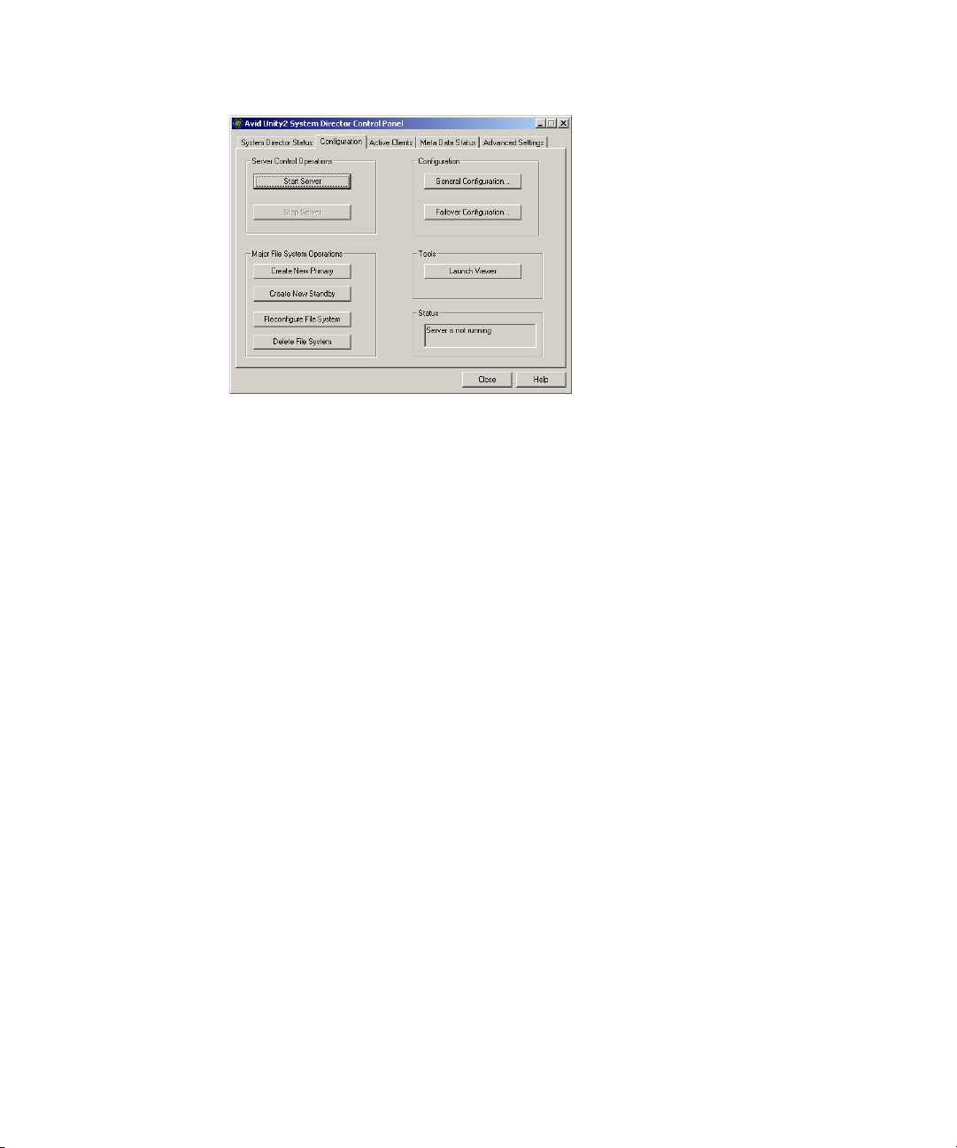
7. Click Close.
Creating New File Systems on the A and B System Directors
87
Page 88

Appendix C
Regulatory and Safety Notices
Warnings and Cautions
w
w
w
w
c
c
c
Never install equipment if it appears damaged.
Disconnect the power cord before servicing the unit.
Only perform the services explicitly described in this document. For services or
procedures not outlined in this document, speak with authorized Avid service
personnel.
“CLASS 1 LED PRODUCT”
Follow all warnings and cautions in the procedures.
Operate the device within its marked electrical ratings and product usage instructions.
Risk of explosion if battery is replaced by an incorrect type. Dispose of used batteries
according to the manufacturer's instructions.
Il y a risque d'explosion si la batterie est remplacÈe par une nouvelle d'un type
diffÈrent. Pour vous dÈbarrasser des batteries usagÈes, suivre les instructions du
manufacturier.
FCC Notice
This device complies with Part 15 of the FCC Rules. Operation is subject to the following
two conditions:
1. This device may not cause harmful interference.
2. This device must accept any interference received, including interference that may cause
undesired operation.
Page 89

This equipment has been tested and found to comply with the limits for a Class A digital
device, pursuant to Part 15 of the FCC Rules. These limits are designed to provide
reasonable protection against harmful interference when the equipment is operated in a
commercial environment. This equipment generates, uses, and can radiate radio frequency
energy and, if not installed in accordance with the instruction manual, may cause harmful
interference to radio communications. Operation of this equipment in a residential area is
likely to cause harmful interference in which case the user will be required to correct the
interference at his own expense.
Canadian ICES-003
This Class A digital apparatus meets all requirements of the Canadian Interference Causing
Equipment Regulations.
Cet appareil numérique de la classe A respecte toutes les exigences du Règlement sur le
matériel brouilleur du Canada.
European Union Notice
Canadian ICES-003
Declaration of Conformity
(According to ISO/IEC Guide 22 and EN 45014)
Application of Council
Directives:
Standards to which
Conformity is Declared:
Manufacturer’s Name: Avid Technology, Inc.
European Contact: Nearest Avid Sales and Service Office or
73/23/EEC, 89/336/EEC.
EN60950:1999 Third Edition
CISPR 22:1997 / EN55022:1994 + A1:1995 + A2:1997 Class A
EN55024:1998/EN61000 — 3-2, 4-2, 4-3, 4-4, 4-5, 4-6, 4-11
1925 Andover Street
Tewksbury, MA 01876, USA
Avid Technology International B.V.
Sandyford Business Center
Unit 3,
Dublin 18, Ireland
89
Page 90

Appendix C Regulatory and Safety Notices
Type of Equipment: Information Technology Equipment
Product Name: Products for the Windows NT, Windows 2000, or Windows XP Operating
System: Avid Adrenaline DNA, Avid DS Nitris DNA, Avid Equinox
Break-Out-B ox, Avid|DS, Avid Xpr ess, Avid Xpress DV, Film Composer,
Media Composer, MediaDock, MediaDock 2+, MediaDrive, MediaRAID,
MEDIArray, MEDIArray Drive, MEDIArray II, MEDIArray II Drive,
Meridien I/O box, NewsCutter, NewsCutter DV, NewsCutter XP,
Pro Tools AVoption|V10, Symphony
Products for the Mac OS X Operating System: Avid Adrenaline DNA,
Avid Xpress, Avid Xpress DV, Film Composer, Media Composer,
MediaDock, MediaDock 2+, MediaDrive, MediaRAID, MEDIArray,
MEDIArray Drive, MEDIArray II, MEDIArray II Drive, Meridien I/O
box, Pro Tools AVoption|V10, Symphony
Products for the UNIX Operating System: AirPlay, AirSPACE, AirSpeed,
DNxchange, VideoSPACE
Products for MediaNetwork and Workgroups: Avid ProEncode, Avid Unity
MediaManager, Avid Unity MediaNetwork (includes System Director),
Avid Unity TransferManager, LANserver, LANserver EX, MEDIArray,
MEDIArray Drive, MEDIArray II, MEDIArray II Drive, MEDIArray ZX,
MEDIArray ZX Drive, Nearchive, PortServer, Vixel switches (8100, 7100,
7200, 9100, 9200), Xdeck
90
Base Model Numbers: None
Product Options: All
Year of Manufacture: 2005
(1) Products for the Windows NT, Windows 2000, or Windows XP Operating System: products were
tested in a typical Avid Adrenaline DNA, Avid DS Nitris DNA, Avid Equinox Break-Out-Box,
Avid|DS, Avid Xpress, Avid Xpress DV, Film Composer, Media Composer, MediaDock, MediaDock
2+, MediaDrive, MediaRAID, MEDIArray, MEDIArray Drive, MEDIArray II, MEDIArray II Drive,
Meridien I/O box, NewsCutter, NewsCutter DV, NewsCutter XP, Pro Tools AVoption|V10, or
Symphony configuration.
(2) Products for the Mac OS X Operating System: products were tested in a typical Avid Adrenaline
DNA, Avid Xpress, Avid Xpress DV, Film Composer, Media Composer, MediaDock, MediaDock 2+,
MediaDrive, MediaRAID, MEDIArray, MEDIArray Drive, MEDIArray II, MEDIArray II Drive,
Meridien I/O box, Pro Tools AVoption|V10, or Symphony configuration.
(3) Products for the UNIX Operating System: products were tested in an AirPlay, AirSpeed,
DNxchange, or VideoSPACE configuration.
Page 91
Disposal of Waste Equipment by Users in the European Union
(4) Products for MediaNetwork and Workgroups: products were tested in a typical Avid ProEncode,
Avid Unity MediaManager, Avid Unity MediaNetwork (includes File Manager), Avid Unity
TransferManager, LANserver, LANserver EX, MEDIArray, MEDIArray Drive, MEDIArray II,
MEDIArray II Drive, MEDIArray ZX, MEDIArray ZX Drive, Nearchive, PortServer, or Xdeck
configuration.
I, the undersigned, hereby declare that the equipment specified above conforms to the above
Directives and Standards.
George R. Smith, Director of Hardware Engineering
Disposal of Waste Equipment by Users in the
European Union
This symbol on the product or its packaging indicates that this product must not be disposed
of with other waste. Instead, it is your responsibility to dispose of your waste equipment by
handing it over to a designated collection point for the recycling of waste electrical and
electronic equipment. The separate collection and recycling of your waste equipment at the
time of disposal will help conserve natural resources and ensure that it is recycled in a
manner that protects human health and the environment. For more information about where
you can drop off your waste equipment for recycling, please contact your local city recycling
office or the dealer from whom you purchased the product.
Australia and New Zealand EMC Regulations
John Kells, Australian Operations Manager
Avid Technology (Australia)
Unit B
5 Skyline Place
French Forest NSW 2086
Australia
Phone: 61-2-8977-4800
91
Page 92

Appendix C Regulatory and Safety Notices
Taiwan EMC Regulations
Taiwan EMC Regulations BSMI Class A EMC Warning
92
Page 93

Taiwan EMC Regulations
93
 Loading...